
A-2120 - Recepteur TOA - Notice d'utilisation et mode d'emploi gratuit
Retrouvez gratuitement la notice de l'appareil A-2120 TOA au format PDF.


| Type de produit | Récepteur audio professionnel |
| Marque | TOA |
| Modèle | A-2120 |
| Dimensions (L x H x P) | 482 x 88 x 375 mm (rack 19" 2U) |
| Poids | 11 kg |
| Alimentation | 230 V CA, 50/60 Hz |
| Consommation électrique | 180 W |
| Puissance de sortie | 120 W stéréo |
| Réponse en fréquence | 20 Hz - 20 kHz |
| Impédance d'entrée | 10 kΩ |
| Impédance de sortie | 4-16 Ω |
| Fonctions principales | Amplification stéréo, entrées micro/ligne, sorties haut-parleurs |
| Entretien et nettoyage | Nettoyage avec un chiffon doux et sec |
| Sécurité | Protection contre les courts-circuits et la surchauffe |
| Pièces détachées et réparabilité | Disponibles auprès du service après-vente TOA |
| Informations générales | Utilisation professionnelle pour sonorisation |
FOIRE AUX QUESTIONS - A-2120 TOA
Questions des utilisateurs sur A-2120 TOA
0 question sur cet appareil. Repondez a celles que vous connaissez ou posez la votre.
Poser une nouvelle question sur cet appareil
Téléchargez la notice de votre Recepteur au format PDF gratuitement ! Retrouvez votre notice A-2120 - TOA et reprennez votre appareil électronique en main. Sur cette page sont publiés tous les documents nécessaires à l'utilisation de votre appareil A-2120 de la marque TOA.
MODE D'EMPLOI A-2120 TOA
A-2060 CU
A-2120 CU
A-2240 CU

natural_image
Line drawing of a rectangular electronic device with multiple switches and ventilation grilles (no text or symbols on the device itself)Please follow the instructions in this manual to obtain the optimum results from this unit. We also recommend that you keep this manual handy for future reference.
TABLE OF CONTENTS
- IMPORTANT SAFETY INSTRUCTIONS.... 3
- SAFETY PRECAUTIONS 3
- GENERAL DESCRIPTION 5
- FEATURES.... 5
- NOMENCLANTURE AND FUNCTIONS
5.1 Front 6
5.2 Rear 6
- CONNECTIONS
6.1. Input Connections 7
6.2. Output Connections 8
6.3. Example of External Equipment Connections 9
- MUTING FUNCTION 9
- INSTALLATION 10
- VOLUME CONTROL SETTINGS 10
- BLOCK LEVEL DIAGRAM 10
- DIMENSIONAL DIAGRAM 11
- SPECIFICATIONS 12
1. IMPORTANT SAFETY INSTRUCTIONS
- Read these instructions.
- Keep these instructions.
- Heed all warnings.
- Follow all instructions.
- Do not use this apparatus near water.
- Clean only with dry cloth.
- Do not block any ventilation openings. Install in accordance with the manufacture's instructions.
- Do not install near any heat sources such as radiators, heat registers, stoves, or other apparatus (including amplifiers) that produce heat.
- Do not defeat the safety purpose of the polarized or grounding-type plug. A polarized plug has two blades with one wider than the other. A grounding type plug has two blades and a third grounding prong. The wide blade or the third prongs are provided for your safety. If the provided plug does not fit into your outlet, consult an electrician for replacement of the obsolete outlet.
- Protect the power cord from being walked on or pinched particularly at plugs, convenience receptacles, and the point where they exit from the apparatus.
- Only use attachments/accessories specified by the manufacturer.
- Use only with the cart, stand, tripod, bracket, or table specified by the manufacturer, or sold with the apparatus.
- When a earth is used, use caution when moving the cart/apparatus combination to avoid injury from tip-over.

natural_image
Symbolic icon of a person pushing a large object, enclosed in a circle with no text or symbols- Unplug this apparatus during lightning storms or when unused for long periods of time.
- Refer all servicing to qualified service personnel. Servicing is required when the apparatus has been damaged in any way, such as power-supply cord or plug is damaged, Liquid has been spilled or objects have fallen into the apparatus, the apparatus has been exposed to rain or moisture, does not operate normally, or has been dropped.
2. SAFETY PRECAUTIONS
- Before installation or use, be sure to carefully read all the instructions in this section for correct and safe operation.
- Be sure to follow all the precautionary instructions in this section, which contain important warnings and/or cautions regarding safety.
• After reading, keep this manual handy for future reference.
Safety Symbol and Message Conventions
Safety symbols and messages described below are used in this manual to prevent bodily injury and property damage which could result from mishandling.
Before operating your product, read this manual first and understand the safety symbols and messages so you are thoroughly aware of the potential safety hazards.

The exclamation point within an equilateral triangle is intended to alert the user to the presence of important operation and maintenance (servicing) instruction in the literature accompanying the appliance.

WARNING
Indicates a potentially hazardous situation which, if mishandled, could result in death or serious personal injury.
When Installing the Unit
- WARNING: Do not expose the unit to rain or an environment where it may be splashed by water or other liquids, as doing so may result in fire or electric shock.
- Use the unit only with the voltage specified on the unit. Using a voltage higher than that which is specified may result in fire or electric shock.
- Do not cut, kink, otherwise damage nor modify the power supply cord. In addition, avoid using the power cord in close proximity to heaters, and never place heavy objects -- including the unit itself -- on the power cord, as doing so may result in fire or electric shock.
- Avoid installing or mounting the unit in unstable locations, such as on a rickety table or a slanted surface. Doing so may result in the unit falling down and causing personal injury and/or property damage.
- The terminals marked with the symbol 4 are hazardous live. The external wiring to these terminals requires installation by an instructed person.
- The apparatus shall be connected to a mains socket outlet with a protective earthling connection.
- The socket-outlet shall be installed near the equipment and the plug shall be easily accessible.
When the Unit is in Use
- Should the following irregularity be found during use, immediately switch off the power, disconnect the power supply plug from the AC outlet and contact your nearest TOA dealer. Make no further attempt to operate the unit in this condition as this may cause fire or electric shock.
- If you detect smoke or a strange smell coming from the unit.
• If water or any metallic object gets into the unit.
• If the unit falls, or the unit ease breaks. - If the power supply cord is damaged (exposure of the core, disconnection, etc.)
• If it is malfunctioning (no tone sounds.)
- To prevent a fire or electric shock, never open no remove the unit case as there are high voltage components inside the unit. Refer all servicing to you nearest TOA dealer.
- Do not place cups, bowls, or other containers of liquid or metallic objects on top of the unit. If they accidentally spill into the unit, this may cause a fire or electric shock.

CAUTION
Indicates a potentially hazardous situation which, if mishandled, could result in moderate or minor personal injury, and/or property damage.
When Installing the Unit
- Never plug in nor remove the power supply plug with wet hands, as doing so may cause electric shock.
- When unplugging the power supply cord, be sure to grasp the power supply plug; never pull on the cord itself. Operating the unit with a damaged power supply cord may cause a fire or electric shock.
- Do not block the ventilation slots in the unit's cover. Doing so may cause heat to build up inside the unit and result in fire.
- Avoid installing the unit in humid or dusty locations, in locations exposed to the direct sunlight, near the heaters, or in locations generating sooty smoke or steam as doing otherwise may result in fire or electric shock.
- To avoid electric shocks, be sure to unplug the unit's power supply cord when connecting speakers.
-
Be sure to follow the instructions below when rackmounting the unit. Failure to do so may cause a fire or personal injury.
• Install the equipment on a stable table or shelf. Fix it with anchor bolts or take other arrangements to prevent it from falling down. -
When connecting the unit's power cord to an AC outlet, use the AC outlet with current capacity allowable to the unit.
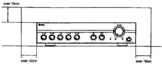
- Keep the 2000 series amplifiers over 10 cm away from objects that may obstruct air flow to prevent the unit's internal temperature rise.
When the Unit is in Use
- Do not operate the unit for an extended period of time with the sound distorting. This is an indication of a malfunction, which in turn can cause heat to generate and result in a fire.
- Switch off the power, and unplug the power supply plug from the AC outlet for safety purposes when cleaning or leaving the unit unused for 10 days or more. Doing otherwise may cause a fire or electric shock.
An all-pole mains switch with a contact separation of at least 3 mm in each pole shall be incorporated in the electrical installation of the building.

The lighting flash with arrowhead symbol, within an equilateral triangle, is intended to alert the user to the presence of uninsulated "dangerous voltage" within the product's enclosure that may be of sufficient magnitude to constitute a risk of electric shock to persons.

ATTENTION
- The equipment should not be exposed to the splashes or flows from any objects filled with liquid (such as vases, cups, glasses, cans, etc.) should not be placed upon the equipment.
3. GENERAL DESCRIPTION
TOA's Basic Amplifiers A-2060, A-2120 and A-2240 are high cost-performance mixer power amplifiers suited for broadcasting paging or background music in schools, offices, shops, factories, mosques, churches and large rooms.
4. FEATURES
• High durability, high reliability, and high cost performance.
- Two microphone inputs, one TEL input, two AUX inputs, and one recording output.
- Speaker output of constant voltage distribution system (25V or 70V) and low impedance (4Ω).
- Muting function.
• Independent input volume controls and master volume control.
- Independent tone controls of boost and cut type for both high and low frequencies.
• MIC 1 with phantom power for condenser microphones.
- Current limiter circuitry protects transistors, and the thermal protection circuitry prevents a failure due to overheat.
• All MIC inputs are electronically-balanced input.
5. NOMENCLATURES AND FUNCTIONS
5.1. Front

1. Power Switch
Press to turn ON the power.
Press again to turn the power STANDBY.
Unplug AC Power Cord to get complete OFF the power.
2. Power Indicator
Lights green when power is switched ON.
3. Signal Indicator
Lights green when power is switched ON, and indicates an output signal.
4. Peak Indicator
Lights red to indicate the output signal reaches the peak level, this indicates that sound is distorted. In such a case, adjust each volume control to reduce output level.
- Microphone Volume Control Adjusts the microphone level.
6. TEL Volume Control
Adjusts the TEL level.
7. AUX Volume Control
Adjusts the AUX level.
8. Bass Control
Adjusts bass response. Rotate clockwise to increase bass output, and counterclockwise to reduce it. The center position provides flat characteristics.
9. Treble Control
Adjusts treble response. Rotate clockwise to increase treble output, and counterclockwise to reduce it. The center position provides flat characteristics.
-
Master Volume Control Adjusts the overall signal level.
-
AC Power Cord Connects to an AC power source.
-
Output Terminals Connect to speakers. When connecting speakers use only one of the speaker output terminals, low or high impedance.
-
Terminal Cover To avoid electric shock by high voltage from output terminal, put back the terminal cover after connecting speaker cords.
-
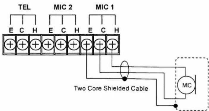
MIC 1 and MIC 2 Inputs • (Mic 1 : Screw Terminals) -60 dB (1mV), 600 Ω, electronically balanced. Not only a dynamic microphone but also phantom powered microphone can connect with only this MIC 1 input.
- When it connects Dynamic Microphone, please set phantom switch in OFF by all means.
• ( Mic 2 : Screw Terminals ) -60 dB (1mV), 600 Ω, electronically balanced.
6. CONNECTIONS
6.1. Input Connections
- Mic 1 Connection (Screw Terminals).
-
TEL Input • (Screw Terminals) -10 dB (300mV), 10 kΩ, transformer isolated.
-
AUX 1 and AUX 2 Input Terminals -20dB (100mV), 10kΩ, unbalanced. Monaural RCA pin jacks. Accept external equipment output signal.
-
Recording Output (REC OUT) 0dB (1V), 600Ω, unbalanced. Outputs all input signals before the master volume control. Connect to a cassette deck, etc when recording the broadcast contents.
-
Muting Sensitivity Control The background music level 30 dB to be automatically reduced 30dB when priority function is operated. Adjusts the input threshold level of Mic1 and Mic2: 0 \~ -64dB, TEL: 0 \~ -23dB to control the mute function.
-
Phantom Switch Selecting to ON position supplies power for condenser microphones from Mic 1. This phantom power is 21V DC.
Caution: Be sure to select OFF position when using the microphone that can not be operated on phantom power. The sound will be distorted.
- Ground Terminal Connect to ground (earth) to avoid electric shock.
Phantom Switch Position
• In the case of Dynamic Microphone
PHANTOM

• In the case of Phantom Power Microphone

• Mic 2 & TEL Connections (Screw Terminals)

• AUX input Connections (RCA pin jack)

natural_image
Simple line drawing of a cylindrical object with a spiral arrow on the left end, connected to a horizontal line with two circular objects on the right (no text or symbols)Signal source (Tuner, Cassette Tape, etc)
One Core Shielded
6.2. Output Connections
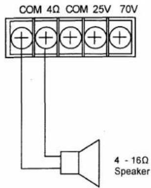
- Low Impedance Speaker
- 25V Line Speaker

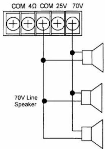
- 70V Line Speaker
CAUTION!
- Tripartite the 4 , 25V and 70V terminals cannot be used at the same time.
- Impedances indicated at the terminal represent the total speaker system (load) impedances.
Total impedances of 70V line:
· 83Ω (A-2060)
·42Ω (A-2120)
· 21Ω (A-2240)
Total impedances of 25V line:
· 10Ω (A-2060)
5Ω (A-2120)
· 2.6Ω (A-2240)

CAUTION
Be sure to attach the supplied terminal cover after connection completion. Because high voltage is applied to the speaker terminals, never touch these terminals to avoid electric shock.
6.3. Example of External Equipment Connections

7. MUTING FUNCTION
Mic 1, Mic 2 and TEL inputs have a priority function and each mutes other inputs by the same priority level. When Mic 1 or Mic 2 or TEL input is used, it takes precedence and automatically reduces. The attenuation level is -30dB fixed at the factory.
The sensitivity input level for operate the function of muting adjustable 0 to -64dB for Mic1 and Mic2 or 0 to -23dB for TEL, which is adjustable with the MUTE SENSITIVITY on the rear panel. If set to 0 it mean the muting function OFF.

Remark: About Mute function.
When signal is in Mic1, Mic2 or TEL, the mute circuit works immediately.
When all the Mic1, Mic2, or TEL it disappears, it return to an old state about 3 seconds later.
8. INSTALLATION
Keep the unit's all sides over 10 cm (3.94 inches) away from object that may obstruct air flow to prevent the unit's internal temperature rise.

9. VOLUME CONTROL SETTINGS
Output levels are adjustable with individual volume controls. For music play or announcement, adjust the corresponding volume control so that the red peak indicator lights intermittently. Note that the sound quality is downgraded when the peak indicator remains lit.
10. BLOCK & LEVEL DIAGRAM

11. DIMENSIONAL DIAGRAM
A-2060 CU
units: mm(inches)
![40 [1.58] 58.4 [2.30]](/content/2026/06/1288956/images/b03ea1b9217726aa391da3e7ba40bb873031bf97d868136a3a12069ed5d083b7.jpg)
![22.8 [0.90] 242.5 [9.55] 15 [0.59] 420 [16.55] 88.4 [3.48] 12.5 [0.49]](/content/2026/06/1288956/images/78f6c348e45cb53358eb834a8782510131cccde1e8accaf84d4eebecb1a5243a.jpg)
● A-2120 CU
A-2240 CU
![40.0 [1.58] 58.4 [2.30]](/content/2026/06/1288956/images/eed995a75de39c9e48a41db0e942b53f18031e730de69f16b647c4ac667632aa.jpg)
![22.8 [0.90] 322.5 [12.71] 15.0 [0.59] 420.0 [16.55] 88.4 [3.48] 12.5 [0.49] This figure represents the A-2120](/content/2026/06/1288956/images/97e4a40db2adae7bb0ce9583ed5731a468bbc8973328a94567f065e7a8f74144.jpg)
12. SPECIFICATIONS
| Model No. | A-2060 CU | A-2120 CU | A-2240 CU | |
| Power Source | 120 V AC, 60Hz | |||
| Rated Output | 60 W | 120 W | 240 W | |
| Power Consumption(IEC60065) | 72 W | 124 W | 238 W | |
| Frequency Response | 50 - 20,000 Hz, ±3 dB | |||
| Distortion | Less Than 1% at 1kHz, 1/3 Rated Power | |||
| Inputs | MIC 1 | -60 dBV (1.0 mV), 600 Ω, Balanced, Screw Terminal | ||
| MIC 2 | -60 dBV (1.0 mV), 600 Ω, Balanced, Screw Terminal | |||
| TEL | -10 dBV (300 mV), 10 kΩ, Transformer Isolated Balanced, Screw Terminal | |||
| AUX 1 | -20 dBV (100 mV), 10 kΩ, Unbalanced, RCA Pin Jack | |||
| AUX 2 | -20 dBV (100 mV), 10 kΩ, Unbalanced, RCA Pin Jack | |||
| Outputs | Speaker Out | All Speaker Outputs are Floating Balanced | ||
| 70 V | 83 Ω | 42 Ω | 21 Ω | |
| 25 V | 10 Ω | 5 Ω | 2.6 Ω | |
| 4Ω | 15.5 V | 22 V | 31 V | |
| Rec Out | 0 dBV (1.0 V), 600 Ω, Unbalanced, RCA Pin Jack | |||
| Phantom Power | DC +21 V (MIC1) | |||
| S/N Ratio | Over 60 dB | |||
| Tone Controls | Bass: ±10 dB at 100HzTreble: ±10 dB at 10kHz | |||
| Muting | MIC1, MIC2 and TEL overrides other input signals with -30 dB attenuation.Sensitivity Input Level adjustable for Mic1, Mic2: 0 to -64dB, TEL: 0 to -23dB(MIC1, MIC2, TEL, same priority level) | |||
| Ventilation | ---- | ---- | Cooling Fan | |
| Indicators | Power LED, Signal LED, Peak LED | |||
| Finish | Panel: ABS Resin, BlackCase: Steel Plate, Black | |||
| Dimensions | 420(W) x 101(H) x 280(D) mm16.5(W) x 4.0(H) x 11.0(D) inches | 420(W) x 101(H) x 360(D) mm16.5(W) x 4.0(H) x 14.2(D) inches | ||
| Weight | 7.0 kg15.43 lb | 10.8 kg23.81 lb | 13.2 kg29.10 lb | |
*) 0 dBV = 1.0 V
**) Specifications are measured on 120V AC for all models.
Note: The design and specifications are subject to change without notice for improvement.
- TABLE OF CONTENTS
- IMPORTANT SAFETY INSTRUCTIONS
- SAFETY PRECAUTIONS
- Safety Symbol and Message Conventions
- WARNING
- When Installing the Unit
- When the Unit is in Use
- CAUTION
- ATTENTION
- GENERAL DESCRIPTION
- FEATURES
- NOMENCLATURES AND FUNCTIONS
- Front
- Power Switch
- Power Indicator
- Signal Indicator
- Peak Indicator
- TEL Volume Control
- AUX Volume Control
- Bass Control
- Treble Control
- CONNECTIONS
- Input Connections
- Phantom Switch Position
- Output Connections
- CAUTION!
- Example of External Equipment Connections
- MUTING FUNCTION
- Remark: About Mute function.
- INSTALLATION
- VOLUME CONTROL SETTINGS
- BLOCK & LEVEL DIAGRAM
- DIMENSIONAL DIAGRAM
- SPECIFICATIONS
Marque : TOA
Modèle : A-2120
Catégorie : Recepteur