
VX3012 - Recepteur JENSEN - Notice d'utilisation et mode d'emploi gratuit
Retrouvez gratuitement la notice de l'appareil VX3012 JENSEN au format PDF.


| Type de produit | Récepteur audio-vidéo |
| Marque | Jensen |
| Modèle | VX3012 |
| Dimensions (L x H x P) | 430 x 150 x 350 mm |
| Poids | 8,5 kg |
| Alimentation | 220-240 V ~ 50/60 Hz |
| Consommation électrique | 500 W (max) |
| Puissance de sortie | 5 x 100 W (sous 8 ohms, 1 kHz, 0,1% DHT) |
| Nombre de canaux | 5.1 |
| Fonctions principales | Amplification audio, décodeur Dolby Digital, entrées HDMI, entrées audio analogiques, radio FM/AM, Bluetooth |
| Entrées HDMI | 3 entrées, 1 sortie (ARC) |
| Entrées audio analogiques | 2 RCA, 1 optique, 1 coaxiale |
| Sorties enceintes | 5 paires de bornes (avant, centre, surround) |
| Connectivité sans fil | Bluetooth 4.2 |
| Radio | FM/AM avec 40 présélections |
| Entretien et nettoyage | Dépoussiérer avec un chiffon doux et sec. Éviter les solvants et l'eau. |
| Sécurité | Ne pas obstruer les ouvertures de ventilation. Débrancher avant nettoyage. |
| Pièces détachées et réparabilité | Indice de réparabilité estimé : 6,5/10. Pièces disponibles via service après-vente agréé. |
| Informations générales | Notice d'utilisation disponible en téléchargement. Tension d'alimentation : 220-240 V. Utilisation en intérieur uniquement. |
FOIRE AUX QUESTIONS - VX3012 JENSEN
Questions des utilisateurs sur VX3012 JENSEN
0 question sur cet appareil. Repondez a celles que vous connaissez ou posez la votre.
Poser une nouvelle question sur cet appareil
Téléchargez la notice de votre Recepteur au format PDF gratuitement ! Retrouvez votre notice VX3012 - JENSEN et reprennez votre appareil électronique en main. Sur cette page sont publiés tous les documents nécessaires à l'utilisation de votre appareil VX3012 de la marque JENSEN.
MODE D'EMPLOI VX3012 JENSEN
JENSEN®
VX3012
Installation / Quick Start Guide
Complete operation manual is online at www.jensenmobile.com
Note: There is no operation manual in this package

What's in the Box
The following items are supplied with the VX3012:
- VX3012 Head Unit
- Trim Ring
- Hardware Bag
• Power/Speaker Output Harness - Remote Control
• External Microphone - Mounting Sleeve & Removal Keys
• Installation / Quick Start Guide
Tools and Supplies
The following tools and supplies are needed to install the VX3012:
- Torx type, flat-head and Philips screwdrivers
- Wire cutters and strippers
- Tools to remove existing radio (screw driver, socket wrench set or other tools)
• Electrical tape - Crimping tool
- Volt meter/test light
- Crimp connections
• 18 gauge wire for power connections
• 16 – 18 gauge speaker wire
WARNING! Never install this unit where operation and viewing could interfere with safe driving conditions.
Steering Wheel Control (SWC) Ready
The recommended SWC Interface is the PAC SWI-RC steering wheel control adapter.
SWI-RC installation hints:
- Set "Radio Select Switch". Set the SWI-RC to position 7 - "Pioneer/Sony/Other".
- Programming - Use the Pioneer/Sony/Other radio function mapping order for Jensen branded head units.
- When programming the SWI-RC, if a function is not supported (or not desired), then the function MUST be skipped as per the PAC SWI-RC instructions.
- The SWC functions MUST be programmed in the correct order per the PAC SWI-RC radio function mapping order instructions.
Disconnect the Battery
To prevent a short circuit, be sure to turn off the ignition and remove the negative (-) battery cable prior to installation.
NOTE: If the VX3012 is to be installed in a car equipped with an on-board drive or navigation computer, do not disconnect the battery cable. If the cable is disconnected, the computer memory may be lost. Under these conditions, use extra caution during installation to avoid causing a short circuit.
Replacing the Fuse
When replacing the vehicles radio fuse always use the proper rated replacement fuse. Using a fuse with an improper rating could damage the unit and cause a fire.
ISO-DIN Installation
The VX3012 is designed to fit into a 1.0 DIN dashboard opening. The unit has threaded holes in the chassis side panels which may be used with the original factory mounting brackets of some Toyota, Nissan, Mitsubishi, Isuzu, Hyundai and Honda vehicles to mount the radio to the dashboard. Please consult with your local car stereo specialty shop for assistance on this type of installation.
-
Remove the existing factory radio from the dashboard or center console mounting. Save all hardware and brackets as they will be used to mount the new radio.
-
Remove the factory mounting brackets and hardware from the existing radio and attach them to the new radio.
CAUTION! Do not exceed M5 X 6MM screw size. Longer screws may damage components inside the chassis.
-
Place the radio in front of the dashboard opening so the wiring can be brought through the mounting sleeve. Follow the wiring diagram carefully and make certain all connections are secure and insulated with wire nuts or electrical tape. After completing the wiring connection, plug the connector into the mating socket on the rear of the chassis. Turn the unit on to confirm operation (vehicle ignition switch must be "ON"). If the unit does not operate, re-check all wiring until the problem is corrected.
-
Mount the new radio assembly to the dashboard or center console using the reverse procedure in step 1 above.
CAUTION! Be careful not to damage the car wiring.

NOTE: It is the end-users responsibility to install and operate this unit in a manner in accordance with local, state and federal laws. The PARKING BRAKE wire MUST BE CONNECTED as directed in the manual.
Using the Cosmetic Trim Ring
A cosmetic trim ring is supplied with the head unit for installation flexibility. This unit will fit into most import dashes with little or no modification to the dash board/cavity. Some US domestic vehicle dashes will accept a Single-DIN chassis, but there is usually a small gap between the radio and dash piece after installation is complete. In this case, use the trim ring to conceal any gaps that may be present.
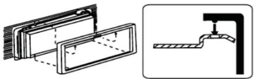
NOTE: For proper operation of the CD/DVD player, the chassis must be mounted within 30° of horizontal. Make sure the unit is mounted within this limitation.


Wiring Diagram
CAUTION! IMPORTANT: Incorrect wiring connections can damage the unit. Follow the wiring instructions carefully, or have the installation handled by an experienced technician.
Need Help? For technical assistance, call the Jensen customer support line at 1-800-323-4815.

Some vehicles may not support all SWC functions. Professional Installation is recommended.


QUICK START GUIDE
Turning the Unit ON or OFF
Press the front panel Power/Menu button [⚡ / SRC ] to turn the unit ON. To turn the unit OFF, press and hold the front panel Power/Menu button [⚡ / SRC ] for 2 seconds.
Selecting an Audio/Video Source, BT or Backup Camera
To access an Audio/Video source:
- Momentarily press the front panel Power/Menu button or touch the Menu icon ↑ located in the upper left corner of the display to view the Main Menu Screen.


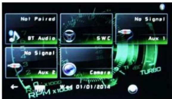
Screen 1 Screen 2
- Touch the desired source icon on one of the two main menu screens. Screen 1 of 2: Radio, Disc, BT, USB. Touch page arrow (-->) at the bottom of the screen to access Screen 2 of 2: BT (Audio), Steering Wheel Control (SWC), AV-IN1, AV-IN2, or Camera.
Volume Adjustment
Volume Increase/Decrease
To increase or decrease the volume level, turn the rotary encoder on the front panel. When the volume level reaches "0" or "50", a beep sounds, indicating that the adjustment limit has been reached. The TFT screen displays the volume level for 3 seconds.
Mute
Press the volume knob on the front panel or press the [MUTE] Button on the remote control to mute the volume from the unit.
Audible Beep Confirmation
An audible beep tone confirms each function selection. The beep tone can be disabled through the Setup menu.
Voxx Electronics Corporation
Hauppauge, NY 11788
Technical Assistance: 800-323-4815
www.jensenmobile.com © 2015 Printed in China
- JENSEN®
- VX3012
- INSTALLATION / QUICK START GUIDE
- COMPLETE OPERATION MANUAL IS ONLINE AT WWW.JENSENMOBILE.COM
- NOTE: THERE IS NO OPERATION MANUAL IN THIS PACKAGE
- WHAT'S IN THE BOX
- TOOLS AND SUPPLIES
- STEERING WHEEL CONTROL (SWC) READY
- SWI-RC INSTALLATION HINTS
- DISCONNECT THE BATTERY
- REPLACING THE FUSE
- ISO-DIN INSTALLATION
- USING THE COSMETIC TRIM RING
- WIRING DIAGRAM
- QUICK START GUIDE
- TURNING THE UNIT ON OR OFF
- SELECTING AN AUDIO/VIDEO SOURCE, BT OR BACKUP CAMERA
- VOLUME ADJUSTMENT
- VOLUME INCREASE/DECREASE
- MUTE
- AUDIBLE BEEP CONFIRMATION
Marque : JENSEN
Modèle : VX3012
Catégorie : Recepteur