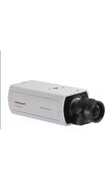
WV-SPN310 - Caméra de surveillance PANASONIC - Notice d'utilisation et mode d'emploi gratuit
Retrouvez gratuitement la notice de l'appareil WV-SPN310 PANASONIC au format PDF.


| Type de produit | Caméra de surveillance réseau |
| Marque | Panasonic |
| Modèle | WV-SPN310 |
| Alimentation | 12 V DC ou PoE (IEEE802.3af) |
| Connectique réseau | RJ45 (catégorie 5 ou supérieure) |
| Connectique audio | Entrée micro/ligne (mini-jack 3,5 mm mono), sortie haut-parleur |
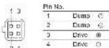
| Connectique alarme | 2 entrées (ALARM IN1/IN2), 1 sortie (ALARM OUT), 1 entrée jour/nuit |
| Stockage | Carte SD (emplacement avec loquet) |
| Fonctions principales | Mise au point arrière automatique (ABF), assistance de mise au point, zoom motorisé (selon objectif), mode jour/nuit |
| Objectif compatible | Objectif type C/CS, monture 14-230G (recommandé : objectif haute résolution Panasonic) |
| Sortie moniteur | BNC (MONITOR OUT) pour réglage |
| Dimensions (approx.) | 80 x 60 x 130 mm |
| Poids (approx.) | 500 g (sans objectif) |
| Entretien et nettoyage | Nettoyer avec un chiffon doux et sec. Ne pas utiliser de solvants ou produits abrasifs. |
| Installation et sécurité | Utiliser le câble de sécurité fourni. S'assurer que le support de montage est solidement fixé. Monter à plus de 2,7 m du sol. |
| Accessoires fournis | Guide d'installation, CD-ROM, câble d'alimentation, vis, rondelles, câble de sécurité, étiquette de code |
| Environnement d'utilisation | Intérieur sec, température de 0 °C à 40 °C |
| Certifications | UL, CSA (alimentation 12 V DC classe 2) |
FOIRE AUX QUESTIONS - WV-SPN310 PANASONIC
Questions des utilisateurs sur WV-SPN310 PANASONIC
0 question sur cet appareil. Repondez a celles que vous connaissez ou posez la votre.
Poser une nouvelle question sur cet appareil
Téléchargez la notice de votre Caméra de surveillance au format PDF gratuitement ! Retrouvez votre notice WV-SPN310 - PANASONIC et reprennez votre appareil électronique en main. Sur cette page sont publiés tous les documents nécessaires à l'utilisation de votre appareil WV-SPN310 de la marque PANASONIC.
MODE D'EMPLOI WV-SPN310 PANASONIC
Panasonic
Installation Guide
Included installation instructions
Network Camera
Model No. WV-SPN311/WV-SPN310

* The fustaton represents 670-5FN31
[Пригор разстановки (на лекаститутной летос запротивных.)]

• The initial balance of total non-provisional costs, operations, and the angle of the product of the product
Before reading the manual, he sure to read the important information.
In a manual discussion how to add all the work, our work model 974-8-10611 can use yourself.
For U.S. and Canada
For Europe and other countries
Panasonic Corporation
11:20amal##
Unit of Panasonic Corporation of North America
(六) 2016年1月1日
For cumulative support, call: 1.800.525.6747
(3) 用 H_2O 和 H_2O 相对, H_2O 进入
Panasonic Canada Inc.
Other, left AR Survey
305124-5010
- 本说明仅供参考。
1008162224 2027-4-31 19:30
Major operating controls
The company's name of the companies are as follows: Ratio in the division when relating to which the camera
- 2017年1月1日
-ACI Industrat
- When data is being sent via the network camera
Binks green (accessing)
UNI construction
•
the connected device
EHEK PANES
372-04116
**Network connector RHS | *1 12 V DC power supply terminal
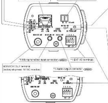
*1 Microphoralline inductor connector
*1 EXT 90 terminals
HONION OUT OF TREN
(basket shipment: M/SC market)
*1 Audio cpu: connector
- The detailed specifications on the right describe terminals with markings.
- SLCXG501K/SD memory range is described as SD memory range.
Standard accessories
importa-l information 1 pc CD-ROM ^4 1 pc
Installation Guide (this document)....1 set Code label ^2 ....1 pro
A. 15
*1 The CD-ROM contains the operating instructions and different kinds of tool software programs.
*2. The label may be required for network management. The blockchain matrix shall switch the code local
The following parts are usual during the course of our course.
⑥ Tixed man, Ison.... 1:20. L. Whabr.... 1 pm
① Power and 34.0 1 pc ② Spring weather 1 pc
(2) call to us, ...
(12.5×0 mm (16 inches)
(£) 1 for away
F. Safetywim 1 pp

About notations
The following relations are used when describing the functions limited for specified models.
The functions are based on the processes are supported by all methods.
The functions with the result are available when using the model Nov-SPN31
C2016: The Lanzons with the random an asamble when using low model GIV-S1W3710.

Depending on the scanning application
used, the Data Kana may not be able to
be read correctly. In this case, excess the site by clearly episode the location.
The following section is written by
supporting so select him.
- 2014年1月1日
MIC Data Matrix: To our website
3D ON/OFF button
Auto back focus button (ABF)

Camp for SD / ALO (no recommendation) Bank recommendations
memory card
SC MOUNTED CABB
- When an 60 memory card is inserted and could
Lights off - 3 links green
be recognized
- When data can be saved after the ED memory card is Lights off — Lights green
inserted and the 60 ON/OFF button is pressed
- When cars can be used in the 50 memory room. I am green. - When the 50 memory card is removed after holding down. Lights were
- While the 50 mmHg light was added after cooling down, Lights green = 2415 g/pc = 87.6 V or the 50 CMHDFE buffer for about 2 seconds.
Alum data cannot be saved to the 3D memory card because Lights off
an abnormality was detected on the SD memory card is
configured not to be seen
INITIAL SET BUTTON
■ Hua 201954-2019
Follow the steps below to initiate the network owners.
①. Типол-Кароми и Ринамия. What could be PcE has, despite the LAN calls from
the camera. When using an external power supply, disconnect the power table plug from
the 12 VIE power supply /w/m3
- Tumun Piu power is the power which turning down the N114, 801100, and then known in the bottom button for 7 seconds or more, about 5 min later for every
Step: If being down the colour of 2 stocks of more, Actel 2 measures that, the car is not very low and low deliver an optimal low-network environment sell its network.
IMPORTANT
- When the camera is initiated, the settings reducing the network settings will be critical
cost. Note that the CRT key (SSL encryption key) used in the HTTPS program will not
be initialized.
- Before traveling the sidewalks, it is recommended to only draw the settings in advance.
- US net turn on the power of the camera during the process implementation. Otherwise,
NISCA% switch
• The MONITOR OUT terminal output can be switched for the NTSC monitorPAL monitor.
[Unreadable]
- This is valid if the (5th order cut) is set to 15000, (4th order cut) is selected by
default. For exactly, refer to the Operating Instructions (included in the CD-ROM).
2018年,3月2日,公司与上海浦东发展银行股份有限公司签订了《关于使用部分闲置募集资金进行现金管理的协议》。
SD ERROR/REF indicator ON/O SD ERROR/F. Industrative
- When ABF (Auto Back Focus) operation is being Binks red interval of 1 time seconds
[Unreadable]
• Alter the territorial London is registered (201)
- When the focus may be searched near the best
- When I was in his
• 1978. 20. 16:30, 1978. 20. 16:30
- 10th en 80 monthly care is recognized locally - 25th, last 50 could slot a unit travel or air travel phone
detected in SD card after the camera has started
Making connections
Turn off each system's power supply before making a connection. Before making connections,
prepare the req.ke
Longest Mid-All Center Longest Mid-All Center
Connect a LAN cable (category 5 or better, straight)
Carned a LAN cellular connectivity S or better, straight) to the network connection
IMPORTANT
• Use all 4 cars (5 pins) of the LAN cable.
• The maximum range length is 100 m (528 mm).
• Make sure that the PuE device in use is completely with IEEE802.5 of standard.
* When controlling both the 12 V DC power supply and the PnE device for power
supply, 12 V DC and be used for power supply.
- In a 12 V DC SOE supply and a PCE hub or router are used at the same time, relevant comments may not be particle in the case, double in fuel cells
The following table provides the information in the United States:
* Depending on the FoE device used. If you disconnect 12 V DC while 12 V DC
power supply and a Pulp, high or lower are used at the same time. The power supply
may stop causing the camera to restart
- When the LAN cable is disconnected once, reconnect the cable after around
2 seconds. When the cable is quickly connected, the power may not be supplied from the FeF device.
from the Po

Connect an external amplifier-embedded speaker to the audio output cbl:
Connect a speed vinyl (192.5 mm) audio cutter is manual! Use an external power speaker:
• Output resistance : Acrylic, SIG D or Infiltrate
- Recommended cable length: Less than 10 m (22.0 feet)
• Output level : -21 dBV
IMPORTANT
- Connect disconnect the audio cables and turn on the power of the camera after turning
of the power of the and an input device. Otherwise, I can not may be heard from
the spocke
- Make sure that the stereo mini plug is connected to this cable. When a monatral mini
put, connected, and may not be heard
Which of nothing a musical speaker with strip Her, Use a locally structured conversion mode (transversion).
Microphone/line input cable
Connect a monocular mini plus 10.5 mm
- Input impedance Approx. 2 kΩ (unbalanced)
- Recommended cable length Less than 1 m (3.28 kpc) for micropore input
Less than 10 m (32.8 mm) [for are equal]
• Кодинтимано творчаги. Рад-п разов грам (одату) • Бидру этира: 2,5 V 211,5 V
• Фрунтового вета, нау. Арф. 10 дз? • Ремонтажная армиталы с тарифами —
- 2023年1月1日,公司召开2023年第一次临时股东大会,并通知全体董事。
When connecting to a network using a PoE hub
Boltes and the illustration check for some asalum or fixation. The following:
gives a wrong example of how to connect the camera to the network via a PoE device (run).
(1) 2017年1月1日

flowchart
graph TD
    A["Microphone"] --> B["Microcontroller"]
    B --> C["Adjuster monitor"]
    C --> D["Full case (multi)"]
    D --> E["LAN case (laptops & better straight)"]
    E --> F["PC"]
    F --> G["Display unit"]
    H["Microphone"] --> I["Microcontroller"]
    I --> J["Adjuster monitor"]
    J --> K["Full case (multi)"]
    K --> L["LAN case (laptops & better straight)"]
    L --> M["PC"]
    M --> N["Display unit"]
    O["Functional device"] --> P["Control panel"]
- Recommendations: cable length from the speaker . less than 10 m (36.5 feet)
Recommended calcs length: Iron-Pa mmolphone : less Par-1 m [325 sec]
Connect the power cable
Cautious
- A READILY ACCESSIBLE DISCONNECT DEVICE SHALL BE INCORPORATED
TO THE EQUIPMENT POWERED BY 12 V DC POWER SUPPLY.
- ONLY CONNECT 12V DC CLASS 2 POWER SUPPLY (UL 13/03A 229) of
LIMITED POWER SOURCE (ECIEMOLCSA 6.000-1)
Connect the output cable of the DC power supply to the power cable plug (accessory).
① Locus the screen of the power cable plug (accessory), ship 3 mm to 7 mm (108 inches to
2/32 inches from the end of the wire laval the wrapped part of the wire sufficiently to avoid
short circuit, and then connect the output cable to the power cable plug (accessory).
(2) Integrated the power of the power in a small field (e.g., ( \beta_{1} ) , ( \beta_{2} ) , ( \beta_{3} ) , ( \beta_{4} ) , ( \beta_{5} ) , ( \beta_{6} ) , ( \beta_{7} ) , ( \beta_{8} ) , ( \beta_{9} ) , ( \beta_{10} ) , ( \beta_{11} ) , ( \beta_{12} ) , ( \beta_{13} ) , ( \beta_{14} ) , ( \beta_{15} ) , ( \beta_{16} ) , ( \beta_{17} ) , ( \beta_{18} ) , ( \beta_{19} ) , ( \beta_{20} ) , ( \beta_{21} ) , ( \beta_{22} ) , ( \beta_{23} ) , ( \beta_{24} ) , ( \beta_{25} ) , ( \beta_{26} ) , ( \beta_{27} ) , ( \beta_{28} ) , ( \beta_{29} ) , ( \beta_{30} ) , ( \beta_{31} ) , ( \beta_{32} ) , ( \beta_{33} ) , ( \beta_{34} ) , ( \beta_{35} ) , ( \beta_{36} ) , ( \beta_{37} ) , ( \beta_{38} ) , ( \beta_{39} ) , ( \beta_{40} ) , ( \beta_{41} ) , ( \beta_{42} ) , ( \beta_{43} ) , ( \beta_{44} ) , ( \beta_{45} ) , ( \beta_{46} ) , ( \beta_{47} ) , ( \beta_{48} ) , ( \beta_{49} ) , ( \beta_{50} ) , ( \beta_{51} ) , ( \beta_{52} ) , ( \beta_{53} ) , ( \beta_{54} ) , ( \beta_{55} ) , ( \beta_{56} ) , ( \beta_{57} ) , ( \beta_{58} ) , ( \beta_{59} ) , ( \beta_{60} ) , ( \beta_{61} ) , ( \beta_{62} ) , ( \beta_{63} ) , ( \beta_{64} ) , ( \beta_{65} ) , ( \beta_{66} ) , ( \beta_{67} ) , ( \beta_{68} ) , ( \beta_{69} ) , ( \beta_{70} ) , ( \beta_{71} ) , ( \beta_{72} ) , ( \beta_{73} ) , ( \beta_{74} ) , ( \beta_{75} ) , ( \beta_{76} ) , ( \beta_{77} ) , ( \beta_{78} ) , ( \beta_{79} ) , ( \beta_{80} ) , ( \beta_{81} ) , ( \beta_{82} ) , ( \beta_{83} ) , ( \beta_{84} ) , ( \beta_{85} ) , ( \beta_{86} ) , ( \beta_{87} ) , ( \beta_{88} ) , ( \beta_{89} ) , ( \beta_{90} ) , ( \beta_{91} ) , ( \beta_{92} ) , ( \beta_{93} ) , ( \beta_{94} ) , ( \beta_{95} ) , ( \beta_{96} ) , ( \beta_{97} ) , ( \beta_{98} ) , ( \beta_{99} ) , ( \beta_{100} = -\frac{1}{2}\pi x + i\pi x^2 + i\pi x^3 + i\pi x^4 + i\pi x^5 + i\pi x^6 + i\pi x^7 + i\pi x^8 + i\pi x^9 + i\pi x^10 + i\pi x^11 + i\pi x^12 + i\pi x^13 + i\pi x^14 + i\pi x^15 + i\pi x^16 + i\pi x^17 + i\pi x^18 + i\pi x^19 + i\pi x^20 + i\pi x^21 + i\pi x^22 + i\pi x^23 + i\pi x^24 + i\pi x^25 + i\pi x^26 + i\pi x^27 + i\pi x^28 + i\pi x^29 + i\pi x^30 + i\pi x^31 + i\pi x^32 + i\pi x^33 + i\pi x^34 + i\pi x^35 + i\pi x^36 + i\pi x^37 + i\pi x^38 + i\pi x^39 + i\pi x^40 + i\pi x^41 + i\pi x^42 + i\pi x^43 + i\pi x^44 + i\pi x^45 + i\pi x^46 + i\pi x^47 + i\pi x^48 + i\pi x^49 + i\pi x^50 + i\pi x^51 + i\pi x^52 + i\pi x^53 + i\pi x^54 + i\pi x^55 + i\pi x^56 + i\pi x^57 + i\pi x^58 + i\pi x^59 + i\pi x^60 + i\pi x^61 + i\pi x^62 + i\pi x^63 + i\pi x^64 + i\pi x^65 + i\pi x^66 + i\pi x^67 + i\pi x^68 + i\pi x^69 + i\pi x^70 + i\pi x^71 + i\pi x^72 + i\pi x^73 + i\pi x^74 + i\pi x^75 + i\pi x^76 + i\pi x^77 + i\pi x^78 + i\pi x^79 + i\pi x^80 + i\pi x^81 + i\pi x^82 + i\pi x^83 + i\pi x^84 + i\pi x^85 + i\pi x^86 + i\pi x^87 + i\pi x^88 + i\pi x^89 + i\pi x^90 + i\pi x^91 + i\pi x^92 + i\pi x^93 + i\pi x^94 + i\pi x^95 + i\pi x^96 + i\pi x^97 + i\pi x^98 + i\pi x^99 + i\pi x^{*}(i)^{*}}
(2018)
Note:
- Check whether the signed part of the case is not acquired and is mostly con-
period
- A##r: c##n##ing; # ##k##: p#e## ##j#y; # ## ##m##er, ## ## ## ###, in the A##s 24 recorded or # m#ed u#d ##elas.
RHO ZHONG HAIQO SHOUHOU WED GAMES
IMPORTANT:
- The 12 VDC power supply shall be enabled from the commercial AC cause
- Be sure to use the power cable plug provided with this product.
- Be sure to fully insert the power cable plug into the 12 V DC power supply terminal
Otherwise, if any damage the camera or cause mechanical.
- When Entailing the camera, make sure that excessive force is not applied to the same mode.
- 2014年
- By date to date at 10.3.24, client will the Securities firm – in the net sales level on the bottom side of this unit, regarding open source and power con
2017年,公司以自有资金进行现金管理,投资于银行理财产品。
Connect the alarm input/output cable
Correct the radius of uroland diameter in the EXT-1D terminal plug.
① When containing an oxide or oxide, between 5 mm - 9 mm of a copper jacket at the central metal layer, were a well known as part.
Soccalpian of coldy (rent. AWG 20 - AWG 28. Scing pnc. wong)
② Push down the lotion of the cated terminal on the external 10 terminal plug with a ball
point pen, and release. The button where the cable of the external device is fully inverted into the external side.
100000
Note:
- Check whether the dropped part of the wire is not exposed and is securely connected
e-Batings
• N. ARM NIDAYOMINE (DOPOL) | 01685192, N. ARM NA
ALARMING
pur specification : No-voltage make contact input (6 V - 5 V DC, normally pulled up)
F : Open to 4 V - 5 V DC
- Main contact with GND (outstanding if an account: 1 m/s in person)
• N. ORAM CUIL AUX CUI
(1) specialization: Diam cobham capital (mechanical words: 31V105)
N : 4V-6VDC by Internal pull-up
- Cropset voltage 1.0 V DC or less (maximum down current: 50 mA)
The default of EXT I/O terminals is "Off".
ALGEMINT, PAYMIGHT IN
(Alarm Input terminal 1. DAY NIGHT input (modulated)
ALARMINE, ALARM OUT
(Alarm input terminal 2, Alarm output command)
[1] [2] [3] [4] [5] [6] [7] [8] [9] [10] [11] [12] [13] [14] [15] [16] [17] [18] [19] [20] [21] [22] [23] [24] [25] [26] [27] [28] [29] [30] [31] [32] [33] [34] [35] [36] [37] [38] [39] [40] [41] [42] [43] [44] [45] [46] [47] [48] [49] [50] [51] [52] [53] [54] [55] [56] [57] [58] [59] [60] [61] [62] [63] [64] [65] [66] [67] [68] [69] [70] [71] [72] [73] [74] [75] [76] [77] [78] [79] [80] [81] [82] [83] [84] [85] [86] [87] [88] [89] [90] [91] [92] [93] [94] [95] [96] [97] [98] [99] [100]
(In millions)
GND
(二) 2017年
Estand 10 terminal pu
IMPORTANT:
• Doudesouw 2001-2004 were a great deal in the world
- But not complete, 2 which of the country is a similar way that it is not necessary, to learn next 2 or more ways, use a splitter.
• Oil, equal, and equal of the other
Evening the setting. Refer to the Operating Instructions on the provided CO-ROM
for further information about the EXT-PO lemnex 2 and 3 (N. ARM B2, 3) readings
PCF, "Arming", "Arming" or "SIX input".
- Instal external services to that they do not exceed the rating of the networks camera.
- 2017年,公司与关联方不存在关联关系。
(An cable (transcurs b or heller, straight)
Use a LAN cable transgear 5 or better, close) when directly encoded the camera to a PC.
IMPORTANT:
• The adjustment member is used for checking the adjustment of the angular field of
show when installing the camera or when servicing. It is not provided for recording
marketing use
- Depending on the monitor, some characters (camera file, preset ID, etc.) may not
be displayed on the screen
- Use a watching bus of a house which is company with -16BASE-T-16BASE-TX. - For FebE hub is required, each network camera must be connected to 12VDC.
- 1974.02.13
- When using 12 V DC, power pump from a FoE hub or rower is not required.
(1) 本次股东大会的召集、召开符合《公司法》及《公司章程》的规定,股东大会的召开符合《公司法》及《公司章程》的规定。
(1) AD = BD = 1
(No text)
[Non-Text]
[Non-Text]

natural_image
Blank white image with no visible content, text, or symbols.
natural_image
Blank white image with no visible content, text, or symbols.
natural_image
Blank white image with no visible content, text, or symbols.
natural_image
Blank white image with no visible content, text, or symbols.
natural_image
Completely blank white image with no visible content, text, or symbols.

![The installation bales are explained using 6 steps. Step1 Step2 Step3 Step4 Step5 ■ For mounting on ceiling [1] Var the position of frame to be made for the ceiling mount bracket (locally known) on the other most pronounced of the ceiling, and make less visible for other modes. [2] Loose the same a mount bracket. Using mechanism to freely move the camera mount bracket. Along the screw thread with the ceiling. [3] Loose the same a mount bracket. Using mechanism to freely move the camera mount bracket. Sores according to the material of the cone where the safety wire is to be installed. Sores according to the safety wire is to be installed.](/content/2026/06/1280613/images/685945f41562edcbaf87ca8ba8c097730ec3262658caa3ea21167d447e62cc39.jpg)

![Step1 Preparations Step2 Mount the lens to the camera [3] Lower: the camera mount lever lifting mechanism to lever lift the camera Figure 10.1.1.1.1.1.1.1.1.1.1.1.1.1.1.1.1.1.1.1.1.1.1.1.1.1.1.1.1.1.1.1.1.1.1.1.1.1.1.1.1.1.1.1.1.1.1.1.1.1.1.2 Figure 10.2.2.2.2.2.2.2.2.2.2.2.2.2.2.2.2.2.2.2.2.2.2.2.2.2.2.2.2.2.2.2.2.2.2.2.2.2.2.2.2.2.2 Figure 10.3.3.3.3.3.3.3.3.3.3.3.3.3.3.3.3.3.3.3.3.3.3.3.3.3.3.3.3.3.3.3.3.3](/content/2026/06/1280613/images/ff7a884c260cbb1a07cbd1a4fcfaceae1a7bf6ed46ec59983ae51db39d2d916e.jpg)












Step3 Insert/remove an SD memory card
When using an SD memory card, go through the following procedure before installing the camera. When removing an SD memory card, reverse the process.
Refer to the Operating Instructions on the provided CD-ROM for further information about the SD memory card settings.
[1] Open the slide power on the side of the camera, insert an 5D memory card fully into the 5D memory card slot until a click is heard.
- insert the SD memory card with its label facing down.
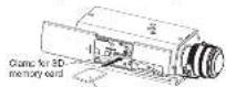
SD memory level
*Late land down
[2] Locuson the screw (M3) of the clamp for the SD memory card, and slide the clamp to the middle, then tighter the screw.
(Recommended tightening torque: 0.19 N·m (0.14 bft))
[3] Close the slide power on the side of the camera.
To remove the 50 memory card, held do
the SD ON/OFF Edition for Seoul 2 seconds. When the lecture SD MOUNT is
that, when the following SD RIGHT FEM control covers out, you can replace the SD
memory card
• After the SD memory card has been
replaced, press the 50 ON/CFF button.
and asks the SD MOUNT Inspector
- If you do not press the SD ON/OFF button
after replacing the SD memory card, the SD
MOUNT indicator is commonly ill sporss-
mainly 5 minutes later.

Comp. for 3D - some of the classes
memory card for 50 memory card
广力云智慧零售收银系统
[Non-Text]
[Non-Text]
Step2 Mount the lens to the camera
The lens section is not included with the camera. It is possible to mount a 142 type video camera lens to the camera. It is recommended to use a recommended high-resolution lens especially when the illuminance level of the photographic subject is low and the camera is used with the lens is open. If a lens other than the recommended lens below is mounted and the camera is used as a resolution of 1200 x 720 or higher, the camera cannot achieve full performance of high resolution.
Refer to our website (http://security parasota.com/ security/support.info.html) for further information about the recommended lens.
When using a lens made by other companies, case a lens that has a protruded portion from the mount face of 200 mm (25/32 inches) or less and a protruded portion from the range face of 4.5 mm (5/32 inches) or less. Lenses without a focus adjustment mechanism and zoom lenses carried be used.

Ions mounting hole of the camera.
② Slowy rotate the lare clockwise to mount the lare and connect the lare.
cable to the ALC lens connector of the
camera.
Step4 Mount the camera
■ Connect the safety wire (E: accessory)
- When securing the camera using a separately procured bracket, use the fixing screw (M4, mostly procured), and the safety wire, washer, and spring washer (accessories).
[1] Engage the safety wire (accessory) with the wire engaging hole.
Safety wire (accessory)

1) Pass and A Phillips has been on-going hole. 2) Pass and A through the other loop of the wire. After mounting
12) Secure for
(2) Become the safety which is necessary to the camera mount.
screw hose with the wire lug hanging
Screw 1 (accessory).
tarqua: 0.39 N·m [0.29 hf·ft]
■ When using the tripod
mount base (A)
- Use the Inpod mount base when mounting the conso to raise the
Mounting the camera to raise the camera mounting position.
- Remove the screw from the camera's
bottom side. Please store the
when you choose to remove the Tiped
mount bees, as they will not be need-
so that it's done on the
[1] Secure the input mount base to the
nation: size of the camera using 2 firing screws. (Recommended unit-
ening forque 0.39 N-m (0.29161-8)
Size of the mounting hole: *164-
2019C camera tripod morning bus
(depth 5 mm (102 mm))
- 2014年1月1日
14-230G camera 1pcd
(115)

The wire images mounted in the safety ring in
[1] of Derivatives, Paraguay, and British Columbia

(accuracy)
The are image reached at the money world lag
[1] of "Correct the safety air" is not about
[Non-Text]
■ For mounting on ceiling
[1] Work the position of house to be made for the ceiling manal house (locally presumed) or the adjacent portion of the plane, and makes house buses for attachment.
Determine the hole diameter and hole depth according to the specifications of the screws as well as holes in be used.
[2] Singare (Iam cemina pucal, Iramak)
[locally prepared] using separately
procured attachment fixing screws or spheres
131 10/68-1
[6] L. H. A. The camera has been a light mechanical tool to properly move the camera
traval bpeke
Align the screw thread with the fixing screw type of the previous and more
526-108
the camera.
Tigger the camera mount bracket to-
ing mechanism and secure the camera mount bracket.
* The triped
[4] Attach the safety wire to the foundation area of
the architecture or where sufficient strength is
sustu 60. Prepare the ring screws according to the material of the area where the safety wire is
to be installed
121951747
- Be sure to rotate and secure the camera mount
Criceline. Rotating the camera places a large bumper as the camera mount bracket, and may
Source of the contents that are shown, and may cause damage.
- The safety wire shall be adjusted to remove slack.
- The distance from the camera is the starting changes depending on the lift angle of the cam-
era. Attach the safety wire in a position accord
nglnth
■ For mounting on wall
[1] Mark the position of holes to be made for the wall mount bracket locally prepared on the
sichment position of the wall, such made these holes for sichment.
Determinable the risks of diameter and hole depth according to the specifications of the screws or other holes to be used.
- 07:02/19. 17:35 (2:30-12:00)
IMPORTANTE
- Mount the bracket in a position higher than 2.7 m (0.56 feet) from the floor
[2] Secure low and mound hocted (mostly
procured) using separately procured
[3] Locusn the camera mount bracket fixing
mechanism to freely move the camera
mount of score.
Augine the saw hole of the camers, and rotate screw holes of the camers, and rotate
the camera mount headset to secure
this camera. Right the camera that blocks facing mechanism and secure
the camera mount bracket.
(на предштая т. Class (высоналу), не не) вид.


[4] Attach the safety wire to the foundation
area of the architecture or where sufficient strength is natural. Descriptive figure
screen according to the material of the area
where the safety wire is to be installed.







IMPORTANT:
- Be sure to rotate and secure the camera mount bracket. Rotating the camera place on a large burden on the camera mount bracket, and may use a device.
- Attach the safety wire in a position higher than the camera and the mount bracket.
- Attach the safety wire so that if the camera were to become detached, it would not fall on nearby people.
(1)
Step5 Connect and adjust the camera
(1) Connecting wires
Connect the necessary cable/lead wires according to the procedure of "Making
connections". (When power is supplied by PoC, the camera is turned on when a LiHy cable is connected. Make sure to connect via LAN cable after a turning of the
power of hub and router.)
(2) Adjusting the camera angle
Connect the adjustment monitor to the MONITOR OUT terminal of the camera with the 80A pin cable locallyvec rack.
Loosean the camera mount bracket fixing mechanism on the camera mount brackets
and then check the adjustment monitor to adjust the camera angle.
When adjusting the camera angle, make sure to close the camera mount bracket fixing mechanism on the camera mount bracket before making adjustments.
Step5 Connect and adjust the camera (Continued)
If the camera angle is changed when the camera mount
bracket fixing mechanism is lighted, successive force
is applied in the car collision
After adjusting the camera and pressure to lighten
camers mount braced fixing mechanism accurately again
[3] Acquiring the focus
① First, reset the back from position by hdding down line side back from location
for 5 seconds or more when the power
operation can also be performed on the setup men
Foster in the Operating Instructions (included in the CD-ROM)
- Manually adjust the angle of view and focus closely by adjusting the zoom and lens as of the lens, and then press the auto bark locus button on the side of the car-
era (page 1) or perform the auto back focus function from the setup method
Refer to the Operating Instructions (included in the CO-ROM) for how to perform the no-back leave injection from the row now.
* How to take a wide depth of field: When focus is desired on entire
distant subjects, select indoor scene mode, or adjust the focus to the midrange
position using manual focus adjustment
Adjusting the focus
The focus is adjusted using the focus assist function
The angle of view and focus can be adjusted in accordance with the distance between the camera lens and a photographic subject. These adjustments shall be performed
together with the camera angle adjustment.
① Lassen the zonm looks inabs, and set up the singh of view
(angular hard or slow) in accordance with the photographic subject by moving the room jack knot and force due
Note
The location may not be adjusted appropriately when the
zoom lock knob is positioned at the "W" (or "T"); and
In this case, adjust the focus again by slightly moving the zoom overs again in the direction of "T" (or "6").
(2) Einkoika (now last) book
- Raise the focus point buffer
— "FOCUS ADJUSTMENT"
The focus social function will be activated to perform
(1) When the focus ring is positioned near the best focus position, the position will be relevant to www.onlinetop. "BEAK HOLD" version.
- Loosen the turns jack knob and may the focus thing
be indicated or "INDICATOR". Adjust the locus position so that the indicator value
guns close to the 'PEAK HOLD' position.
- When the indicator value goes to the best focus position, "BEST FOCUS" will be
displayed at the lower right corner of the screen, then later the focus lock knob. Press the focus assist button again to close the "FOCUS ADJUSTMENT" menu.
(No operation for 3 seconds also closes the menu.)
Note:
• The most common use of a vertical lens and a 700 mm lens
Note that the adjustment method is different depending on the type. For further information, refer to the executive instructions for the type to be used
When the following table is to be open by a publication for the links to the case: "When using 8x or 10x lens, adjust the back focus after positioning the
zoom ring at the "in" end and positioning the focus ring at a step short of
When using 2x or 3x lens adjust the back focus after positioning the
zoom ring at the "T" end and portioning the locus ring at a step short of
The 'F' and (GND)
"In direction, the periphery may become dark. In such a case, while the
zoom ring in the "T" direction for readjustment.
When imagine in the real-infrared light and change from the cover field to the black & white mask, outside areas may be occurred. Seating in line
nature of optical property. In this case, the focus can be corrected by
selecting "Auto" or "Preset" for "Adjusting method" on the setup menu.
Level change since the focus is corrected. Refer to the Operating
Instructions (included in the CD-ROM) for how to configure the "Adjusting
method" setting on the soup menu. CMBD a. (When showing the Inflow node, it can have difficulty adjusting the
which showing the following subjects: It may have difficulty obtaining the back focus position automatically. In this case, adjust the back focus
position manually from the setup menu. Refer to the Operating
instruments (increased in the OS-RU) of how to perform the auto mode focus function from the setup menu.
When shooting the following subjects or in the following places, close the
"FOCUS ADJUSTMENT" menu by pressing the focus oscillator (FA.) but, and adjust the focus to claim the best focus position while monitor
in images from the camera.
- Subj. moves frequently
- Subj. with large illuminance change - Subj. with low illuminance
- Subthrough a window
- Subj. with less contrast surfaces while well
- Subj. with heavy flicks
In case the angular line of view has changed during adjustment, close the "FOCUS ADJUSTMENT" means by pressing the force wave (FA)
Button. (When the angular field of view changes, the indicator values of
"PEAK HOLD" and "INDICATO" also change.) After long the angular fold of view over the FOCUS ADJUSTMENT more by coming line
have assist (F.A.) button, then adjust the focus again.
IMPORTANT
- After performing basic adjustments, make sure to prove the auto-bank focus
buston once to perform detailed adjustments.
After connecting the camera, refer to "Configure the settings of the cam-
era" (leaflet) and perform the camera settings.
14-230G camera tripod mounting hole (depth: 9 mm (115% automatic))
[Table 2.0.1]
"The are image reached at the money world lag in [1] of 'Connect the safety wise' is not shown
(45 operation for 3 seconds also close the menu.)
the (unknown) and perform the camera settings.


- Panasonic
- Major operating controls
- Standard accessories
- About notations
- 3D ON/OFF button
- Making connections
- Connect the power cable
- Step3 Insert/remove an SD memory card
- Step2 Mount the lens to the camera
- Step4 Mount the camera
- ■ When using the tripod
- [Non-Text]
- ■ For mounting on ceiling
- 121951747
- ■ For mounting on wall
- IMPORTANTE
- IMPORTANT:
- Step5 Connect and adjust the camera
- Step5 Connect and adjust the camera (Continued)
- Note:
- IMPORTANT
Marque : PANASONIC
Modèle : WV-SPN310
Catégorie : Caméra de surveillance