
MultiSync V421 - Moniteur NEC - Notice d'utilisation et mode d'emploi gratuit
Retrouvez gratuitement la notice de l'appareil MultiSync V421 NEC au format PDF.


| Type de produit | Moniteur professionnel LCD |
| Marque | NEC |
| Modèle | MultiSync V421 |
| Diagonale de l'écran | 42 pouces (107 cm) |
| Résolution native | 1920 x 1080 (Full HD) |
| Type de dalle | LCD TFT à rétroéclairage LED |
| Dimensions (L x H x P) | 998 x 590 x 96 mm (sans socle) |
| Poids | Environ 20 kg (sans socle) |
| Alimentation électrique | 100-240 V AC, 50/60 Hz |
| Consommation électrique (typique) | 200 W |
| Entrées vidéo | HDMI (2), DisplayPort, VGA, DVI-D |
| Entrée audio | Prise jack 3,5 mm |
| Sortie audio | Prise jack 3,5 mm (casque) |
| Haut-parleurs intégrés | 2 x 10 W |
| Fonctions principales | Affichage professionnel, mode d'économie d'énergie, compatibilité montage mural VESA |
| Entretien et nettoyage | Nettoyer avec un chiffon doux et sec. Ne pas utiliser de produits liquides ou abrasifs. |
| Consignes de sécurité | Installer sur une surface stable, assurer une ventilation adéquate, débrancher avant nettoyage. |
| Pièces détachées et réparabilité | Télécommande, adaptateur secteur, câbles. Réparation par un technicien qualifié recommandée. |
| Informations générales | Notice d'utilisation disponible en PDF. Garantie constructeur standard. |
FOIRE AUX QUESTIONS - MultiSync V421 NEC
Questions des utilisateurs sur MultiSync V421 NEC
0 question sur cet appareil. Repondez a celles que vous connaissez ou posez la votre.
Poser une nouvelle question sur cet appareil
Téléchargez la notice de votre Moniteur au format PDF gratuitement ! Retrouvez votre notice MultiSync V421 - NEC et reprennez votre appareil électronique en main. Sur cette page sont publiés tous les documents nécessaires à l'utilisation de votre appareil MultiSync V421 de la marque NEC.
MODE D'EMPLOI MultiSync V421 NEC
User's Manual

natural_image
Empty rectangular frame with corner brackets and a small rectangular cutout at the bottom right (no text or symbols)MultiSync V321
MultiSync V421
MultiSync V461
Important Information .... English-1
Warning, Caution .... English-1
Registration Information .... English-1
Safety Precautions, Maintenance & Recommended Use .... English-3
Contents .... English-4
Installation .... English-5
Parts Name and Functions .... English-8
Control Panel....English-8
Terminal Panel .... English-9
Wireless Remote Control ...... English-10
Operating Range for the Remote Control.... English-11
Handling the remote control .... English-11
Setup....English-12
Connections ...... English-14
Wiring Diagram....English-14
Connecting a Personal Computer .... English-14
Connecting a DVD Player with HDMI out .... English-15
Basic Operation .... English-16
Power ON and OFF Modes ...... English-16
Power Indicator ...... English-17
Using Power Management .... English-17
Selecting a video source .... English-17
Picture Size .... English-17
Picture Mode .... English-17
Information OSD English-18
OSD (On-Screen-Display) Controls English-18
PICTURE....English-19
ADJUST English-19
AUDIO ...... English-20
SCHEDULE ...... English-20
PIP English-20
OSD English-20
MULTI DISPLAY .... English-21
DISPLAY PROTECTION .... English-21
ADVANCED OPTION .... English-22
Controlling the LCD monitor via RS-232C Remote Control .... English-24
Controlling the LCD monitor via LAN Control .... English-25
Features ...... English-28
Troubleshooting .... English-29
Specifications - V321 English-30
Specifications - V421 English-31
Specifications - V461 English-32
Pin Assignment ...... English-33
Manufacturer's Recycling and Energy Information .... English-34
Important Information

WARNING

TO PREVENT FIRE OR SHOCK HAZARDS, DO NOT EXPOSE THIS UNIT TO RAIN OR MOISTURE. ALSO, DO NOT USE THIS UNIT'S POLARIZED PLUG WITH AN EXTENSION CORD RECEPTACLE OR OTHER OUTLETS UNLESS THE PRONGS CAN BE FULLY INSERTED.
REFRAIN FROM OPENING THE CABINET AS THERE ARE HIGH VOLTAGE COMPONENTS INSIDE. REFER SERVICING TO QUALIFIED SERVICE PERSONNEL.

CAUTION

CAUTION:
TO REDUCE THE RISK OF ELECTRIC SHOCK, MAKE SURE POWER CORD IS UNPLUGGED FROM WALL SOCKET. TO FULLY DISENGAGE THE POWER TO THE UNIT, PLEASE DISCONNECT THE POWER CORD FROM THE AC OUTLET. DO NOT REMOVE COVER (OR BACK). NO USER SERVICEABLE PARTS INSIDE. REFER SERVICING TO QUALIFIED SERVICE PERSONNEL.

This symbol warns user that uninsulated voltage within the unit may have sufficient magnitude to cause electric shock. Therefore, it is dangerous to make any kind of contact with any part inside this unit.

This symbol alerts the user that important literature concerning the operation and maintenance of this unit has been included. Therefore, it should be read carefully in order to avoid any problems.
CAUTION: Please use the power cord provided with this display in accordance with the table below. If a power cord is not supplied with this equipment, please contact your supplier. For all other cases, please use a power cord that matches the AC voltage of the power outlet and has been approved by and complies with the safety standard of your particular country.
| Plug Type | North America | European Continental | U.K. | Chinese | Japanese |
| Plug Shape |  | 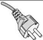 |  |  |  |
| Region | U.S.A./Canada | EU (except U.K.) | U.K. | China | Japan |
| Voltage | 120° | 230 | 230 | 220 | 100 |
*When operating the MultiSync LCD monitor with its AC 125-240V power supply, use a power supply cord that matches the power supply voltage of the AC power outlet being used.
NOTE: This product can only be serviced in the country where it was purchased.
Registration Information
Declaration
| Declaration of the Manufacturer | |
| We hereby certify that the color monitor MultiSync and marked with V321 (L329N8)/MultiSync V421 (L429N9)/MultiSync V461 (L469NA) are in compliance with Council Directive 2006/95/EC: - EN 60950-1 Council Directive 2004/108/EC: - EN 55022 - EN 61000-3-2 - EN 61000-3-3 - EN 55024 Council Directive 2009/125/EC: EC No. 642/2009 - EN 62301:2005 |  NEC Display Solutions, Ltd. 4-13-23, Shibaura, Minato-Ku Tokyo 108-0023, Japan NEC Display Solutions, Ltd. 4-13-23, Shibaura, Minato-Ku Tokyo 108-0023, Japan |
Canadian Department of Communications Compliance Statement
DOC: This Class B digital apparatus meets all requirements of the Canadian Interference-Causing Equipment Regulations. C-UL: Bears the C-UL Mark and is in compliance with Canadian Safety Regulations according to CAN/CSA C22.2 No. 60950-1.
FCC Information
- Use the attached specified cables with the MultiSync V321 (L329N8)/MultiSync V421 (L429N9)/MultiSync V461 (L469NA) color monitor so as not to interfere with radio and television reception.
(1) Please use the supplied power cord or equivalent to ensure FCC compliance.
(2) Please use the supplied shielded video signal cable, Mini D-SUB 15 pin to Mini D-SUB 15 pin.
- This equipment has been tested and found to comply with the limits for a Class B digital device, pursuant to part 15 of the FCC Rules. These limits are designed to provide reasonable protection against harmful interference in a residential installation. This equipment generates, uses, and can radiate radio frequency energy, and, if not installed and used in accordance with the instructions, may cause harmful interference to radio communications. However, there is no guarantee that interference will not occur in a particular installation. If this equipment does cause harmful interference to radio or television reception, which can be determined by turning the equipment off and on, the user is encouraged to try to correct the interference by one or more of the following measures:
• Reorient or relocate the receiving antenna.
- Increase the separation between the equipment and receiver.
- Connect the equipment into an outlet on a circuit different from that to which the receiver is connected.
- Consult your dealer or an experienced radio/TV technician for help.
If necessary, the user should contact the dealer or an experienced radio/television technician for additional suggestions. The user may find the following booklet, prepared by the Federal Communications Commission, helpful: "How to Identify and Resolve Radio-TV Interference Problems." This booklet is available from the U.S. Government Printing Office, Washington, D.C., 20402, Stock No. 004-000-00345-4.
Declaration of Conformity
This device complies with Part 15 of FCC Rules. Operation is subject to the following two conditions. (1) This device may not cause harmful interference, and (2) this device must accept any interference received, including interference that may cause undesired operation.
| U.S. Responsible Party:Address:Tel. No.: | NEC Display Solutions of America, Inc.500 Park Boulevard, Suite 1100Itasca, Illinois 60143(630) 467-3000 |
Type of Product: Display Monitor
Equipment Classification: Class B Peripheral
Model: MultiSync V321 (L329N8)
MultiSync V421 (L429N9)
MultiSync V461 (L469NA)

We hereby declare that the equipment specified above conforms to the technical standards as specified in the FCC Rules.
Windows is a registered trademark of Microsoft Corporation. NEC is a registered trademark of NEC Corporation. All other brands and product names are trademarks or registered trademarks of their respective owners.

HDMI, the HDMI logo and High-Definition Multimedia Interface are trademarks or registered trademarks of HDMI Licensing LLC in the United States and other countries.

Safety Precautions, Maintenance & Recommended Use
FOR OPTIMUM PERFORMANCE, PLEASE NOTE THE FOLLOWING WHEN SETTING UP AND USING THE MULTI-FUNCTION MONITOR:
- DO NOT OPEN THE MONITOR. There are no user serviceable parts inside and opening or removing covers may expose you to dangerous shock hazards or other risks. Refer all servicing to qualified service personnel.
- Do not spill any liquids into the cabinet or use your monitor near water.
- Do not insert objects of any kind into the cabinet slots, as they may touch dangerous voltage points, which can be harmful or fatal or may cause electric shock, fire or equipment failure.
- Do not place any heavy objects on the power cord. Damage to the cord may cause shock or fire.
- Do not place this product on a sloping or unstable cart, stand or table, as the monitor may fall, causing serious damage to the monitor.
- The power supply cord you use must have been approved by and comply with the safety standards of your country. (Type H05VV-F 3G 1mm² should be used in Europe)
• In UK, use a BS-approved power cord with molded plug having a black (13A) fuse installed for use with this monitor.
- Do not place any objects onto the monitor and do not use the monitor outdoors.
- The lamps in this product contain mercury. Please dispose according to state, local or federal law.
- Do not bend, crimp or otherwise damage the power cord.
• If glass is broken, handle with care.
• Do not cover vent on monitor.
- Do not use monitor in high temperature, humid, dusty, or oily areas.
- If monitor or glass is broken, do not come in contact with the liquid crystal and handle with care.
- Allow adequate ventilation around the monitor, so that heat can properly dissipate. Do not block ventilated openings or place the monitor near a radiator or other heat sources. Do not put anything on top of the monitor.
- The power cable connector is the primary means of detaching the system from the power supply. The monitor should be installed close to a power outlet, which is easily accessible.
- Do not move or mount this product by hanging a rope or wire to the backside handle.
Do not mount or secure this product by using the backside handle. It may fall and cause personal injury.
- Handle with care when transporting. Save packaging for transporting.
- Do not touch LCD panel surface while transporting, mounting and setting. Applying pressure on the LCD panel can cause serious damage.
- Please clean the holes of back cabinet to reject dirt and dust at least once a year because of set reliability.
- If using the cooling fan continuously, it's recommended to wipe holes a minimum of once a month.
- When using a LAN cable, do not connect to a peripheral device with wiring that might have excessive voltage.
Immediately unplug your monitor from the wall outlet and refer servicing to qualified service personnel under the following conditions:
- When the power supply cord or plug is damaged.
- If liquid has been spilled, or objects have fallen into the monitor.
• If the monitor has been exposed to rain or water.
• If the monitor has been dropped or the cabinet damaged. - If you notice any structural damage such as cracks or unnatural wobbling.
- If the monitor does not operate normally by following operating instructions.
Recommended Use
• For optimum performance, allow 20 minutes for warm-up.
- Rest your eyes periodically by focusing on an object at least 5 feet away. Blink often.
- Position the monitor at a 90° angle to windows and other light sources to minimize glare and reflections.
- Clean the LCD monitor surface with a lint-free, non-abrasive cloth. Avoid using any cleaning solution or glass cleaner!
- Adjust the monitor's brightness, contrast and sharpness controls to enhance readability.
- Avoid displaying fixed patterns on the monitor for long periods of time to avoid image persistence (after image effects).
• Get regular eye checkups.
Ergonomics
To realize the maximum ergonomic benefits, we recommend the following:
- Use the preset Size and Position controls with standard signals.
• Use the preset Color Setting.
• Use non-interlaced signals. - Do not use primary color blue on a dark background, as it is difficult to see and may produce eye fatigue due to insufficient contrast.
Cleaning the LCD Panel
- When the liquid crystal panel is dusty, gently wipe with a soft cloth.
- Please do not rub the LCD panel with hard material
- Please do not apply pressure to the LCD surface.
- Please do not use OA cleaner as it will cause deterioration or discolor on the LCD surface.
Cleaning the Cabinet
• Unplug the power supply
• Gently wipe the cabinet with a soft cloth
- To clean the cabinet, dampen the cloth with a neutral detergent and water, wipe the cabinet and follow with a dry cloth.
NOTE: The surface of the cabinet is composed of many types of plastic. DO NOT clean with benzene thinner, alkaline detergent, alcoholic system detergent, glass cleaner, wax, polish cleaner, soap powder, or insecticide. Rubber or vinyl should not be in contact with the cabinet for an extended period of time. These types of fluids and materials can cause the paint to deteriorate, crack or peel.
Your new MultiSync monitor box* should contain the following:
- LCD monitor
- Power Cord*1
• Video Signal Cable -
Setup Manual
• Wireless Remote Control and AAA Batteries -
Main switch cover
- Clamp x 2
- Screw for clamp (M4 x 8) x 2
- Screw for main switch cover (3 x 6) x 2
- CD-ROM

natural_image
Coiled cable with two connectors (no text or symbols visible)Video Signal Cable
(Mini D-SUB 15 pin to
Mini D-SUB 15 pin)

natural_image
Coiled electrical plug and socket (no text or symbols visible)Power Cord*1

natural_image
Empty rectangular frame with corner brackets and a small icon at the bottom right (no text or symbols)
Screw for clamp
(M4 × 8) × 2

Screw for main switch
cover (3 x 6) x 2

Clamp x 2

CD-ROM

Setup Manual

natural_image
Line drawing of a NEC remote control with buttons and two cylindrical batteries (no text or symbols on the device itself)Wireless Remote Control
and AAA Batteries
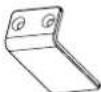
Main switch cover
*1 Type and number of power cords included will depend on the where the LCD monitor is to be shipped. When more than one power cord is included, please use a power cord that matches the AC voltage of the power outlet and has been approved by and complies with the safety standard of your particular country.
* Remember to save your original box and packing material to transport or ship the monitor.
This device cannot be used or installed without the Tabletop Stand or other mounting accessory for support. For proper installation it is strongly recommended to use a trained, NEC authorized service person. Failure to follow NEC standard mounting procedures could result in damage to the equipment or injury to the user or installer. Product warranty does not cover damage caused by improper installation. Failure to follow these recommendations could result in voiding the warranty.
Mounting
DO NOT mount the monitor yourself. Please ask dealer. For proper installation it is strongly recommended to use a trained, qualified technician. Please inspect the location where the unit is to be mounted. Mounting on wall or ceiling is the customer's responsibility. Not all walls or ceilings are capable of supporting the weight of the unit. Product warranty does not cover damage caused by improper installation, remodelling, or natural disasters. Failure to comply with these recommendations could result in voiding the warranty.
DO NOT block ventilated openings with mounting accessories or other accessories.
For NEC Qualified Personnel:
To insure safe installation, use two or more brackets to mount the unit. Mount the unit to at least two points on the installation location.
Please note the following when mounting on wall or ceiling
- When using mounting accessories other than those that are NEC approved, they must comply with the VESA-compatible (FDMIv1) mounting method.
- NEC strongly recommends using size M6 screws (9-10 mm + thickness of bracket and washer in length). If using screws longer than 9-10 mm, check the depth of the hole. (Recommended Fasten Force: 310 - 410 N•cm) NEC recommends mounting interfaces that comply with UL1678 standard in North America.

Screw length should equal depth of hole (9-10 mm) + the thickness of mounting bracket and washer. Bracket hole should be under 7 mm.
- Prior to mounting, inspect the installation location to insure that it is strong enough to support the weight of the unit so that the unit will be safe from harm.
• Refer to the instructions included with the mounting equipment for detailed information.
Weight of LCD assembly:
- MultiSync V321: 14.3 kg/31.5 lbs
- MultiSync V421: 20.5 kg/45.2 lbs
- MultiSync V461: 24.0 kg/52.9 lbs
Orientation
- When using the display in the portrait position, the monitor should be rotated clockwise so that the left side is moved to the top and the LED indicator light is on the bottom. This will allow for proper ventilation and will extend the lifetime of the monitor. Improper ventilation may shorten the lifetime of the monitor.
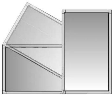
natural_image
Pure geometric diagram showing two overlapping rectangular panels with diagonal lines, no text or symbols present.Mounting location
- The ceiling and wall must be strong enough to support the monitor and mounting accessories.
- DO NOT install in locations where a door or gate can hit the unit.
- DO NOT install in areas where the unit will be subjected to strong vibrations and dust.
- DO NOT install near where the main power supply enters the building.
- Do not install where people can easily grab and hang onto the unit or the mounting apparatus.
- When mounting in a recessed area, as in a wall, leave at least 4 inches (10cm) of space between the monitor and the wall for proper ventilation.
- Allow adequate ventilation or provide air conditioning around the monitor, so that heat can properly dissipate away from the unit and mounting apparatus.
Mounting on ceiling
- Ensure that the ceiling is sturdy enough to support the weight of the unit and the mounting apparatus over time, against earthquakes, unexpected vibrations, and other external forces.
- Be sure the unit is mounted to a solid structure within the ceiling, such as a support beam. Secure the monitor using bolts, spring lock washers, washer and nut.
- DO NOT mount to areas that have no supporting internal structure. DO NOT use wood screws or anchor screws for mounting. DO NOT mount the unit to trim or to hanging fixtures.
Maintenance
- Periodically check for loose screws, gaps, distortions, or other problems that may occur with the mounting apparatus. If a problem is detected, please refer to qualified personnel for service.
- Regularly check the mounting location for signs of damage or weakness that may occur over time.
Attaching Mounting Accessories
The display is designed for use with the VESA mounting system.
1. Attach Mounting Accessories
Be careful to avoid tipping monitor when attaching accessories.
V321

NOTE: Regarding VESA mounting interface patterns on V321, it is not centered over the Vertical Centerline of screen as the above figure.
V421 and V461

Mounting accessories can be attached with the monitor in the face down position. To avoid damaging the screen face, place the protective sheet on the table underneath the LCD. The protective sheet was wrapped around the LCD in the original packaging. Make sure there is nothing on the table that can damage the monitor.
When using mounting accessories other than NEC compliant and approved, they must comply with the VESA-compatible mounting method.
2. Using optional table top stand
CAUTION: Installing and removing the stand must be done by two or more people.
Installing and removing optional table top stand
To install, follow those instructions included with the stand or mounting apparatus. Use only those devices recommended by the manufacturer.
Handle with care when mounting LCD monitor stand and avoid pinching your fingers.
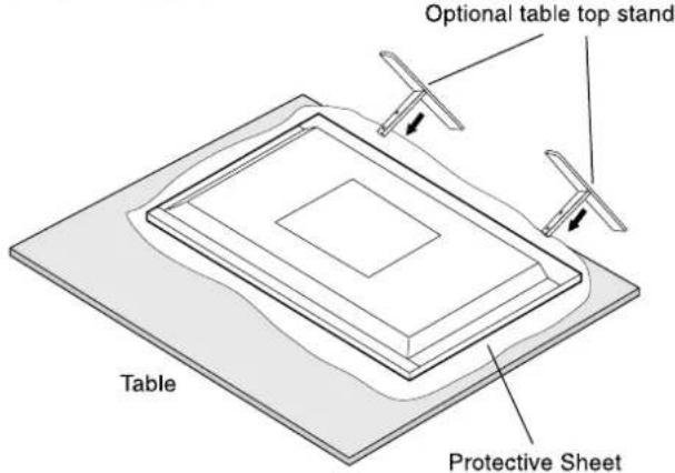
NOTE: ST-3215 is for V321. Use the Thumbscrews included with ST-3215. ST-4020 is for V421 and V461. (V421 and V461 are not mentioned in ST-4020 manual). Before using optional table top stand, remove installed thumbscrews from the display first. Please use a screwdriver for removing thumbscrews as necessary.
3. Ventilation Requirements
When mounting in an enclosed space or recessed area, leave adequate room between the monitor and the enclosure to allow heat to disperse, as shown below.

Allow adequate ventilation or provide air conditioning around the monitor, so that heat can properly dissipate away from the unit and mounting apparatus; especially when you use monitors in a multiple screen environment.
4. Prevent Tipping
When using the display with the Tabletop Stand fasten the LCD to a wall using a cord or chain that can support the weight of the monitor in order to prevent the monitor from falling. Fasten the cord or chain to the monitor using the provided clamp and screw.
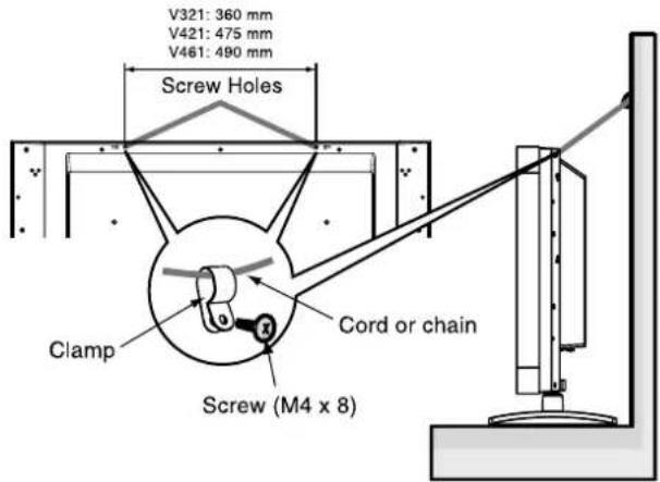
Before attaching the LCD monitor to the wall, make sure that the wall can support the weight of the monitor.
Be sure to remove the cord or chain from the wall before moving the LCD.
Control Panel
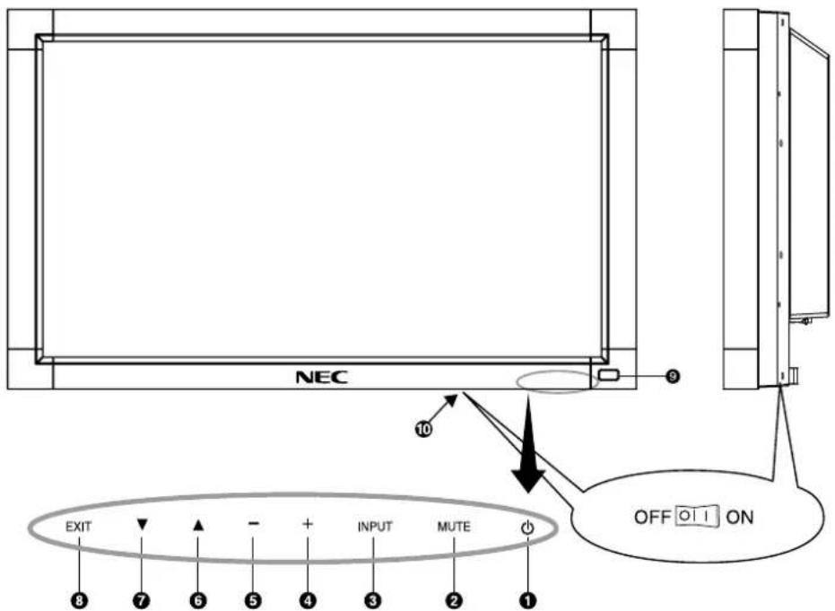
① POWER button (⏻)
Switches the power on/off. See also page 16.
② MUTE button
Switches the audio mute ON/OFF.
③ INPUT button
Acts as SET button within OSD menu. Shows Input select menu for [DVI], [VGA], [RGB/HV], [HDMI], [DVD/HD], [S-VIDEO], [VIDEO1], [VIDEO2].
④ PLUS (+) button
Acts as (+) button to increase the adjustment with OSD menu. Increases the audio output level when the OSD menu is turned off.
⑤ MINUS (-) button
Acts as (-) button to decrease the adjustment with OSD menu. Decreases the audio output level when the OSD menu is turned off.
⑥ UP (▲) button
Acts as ▲ button to move the highlighted area up to select adjustment items within OSD menu.
⑦ DOWN (▼) button
Acts as ▼ button to move the highlighted area down to select adjustment items within OSD menu.
⑧ EXIT button
Activates the OSD menu when the OSD menu is turned-off. Acts as EXIT button within the OSD to move to previous menu.
⑨ Remote control sensor and Power Indicator
Receives the signal from the remote control (when using the wireless remote control). See also page 10. Glows green when the LCD monitor is in active mode. Glows red when the LCD is in POWER OFF mode. When the LCD monitor is in POWER SAVE mode, it will glow both green and red. When SCHEDULE is enabled, it will blink green and glow red. See page 17. When a component failure is detected within the monitor, the indicator will blink red.
⑩ Main Power Switch
On/Off switch to turn main power ON/OFF. See also page 16.
Control Key Lock Mode
This control completely locks out access to all Control Key functions. To activate the control key lock function, press both ▼ and ▲ and hold down simultaneously for more than 3 seconds. To resume user mode, press both ▼ and ▲ and hold simultaneously for more than 3 seconds.
Terminal Panel

① AC IN connector
Connects with the supplied power cord.
② DVI IN (DVI-D)
To input digital RGB signals from a computer or HDTV device having a digital RGB output.
* This connector does not support analog input.
③ VGA IN (mini D-Sub 15 pin)
To input analog RGB signals from a personal computer or from other RGB equipment.
④ RGB/HV IN [R, G, B, H, V] (BNC)
To input analog RGB signals or signals from other RGB equipment. This is also to connect equipment such as a DVD player, HDTV device and Set-Top-Box. This input can be used with an RGB, DVD/HD or Video source. Please select signal type in TERMINAL SETTING on ADVANCED MENU.
| R | G | B | H | V | |
| RGB/HV | R | G | B | H | V |
| DVD/HD | Pr | Y | Pb | ||
| VIDEO2 | VIDEO |
⑤ RGB OUT (mini D-Sub 15 pin)
To output the signal from the VGA and RGB/HV IN connector to an input on a separate device.
⑥ HDMI Connector
To input digital HDMI signals.
⑦ AUDIO IN 1, 2, 3
To input audio signal from external equipment such as a computer, VCR or DVD player.
⑧ AUDIO OUT
To output the audio signal from the AUDIO IN 1, 2 and 3 jack to an external device (stereo receiver, amplifier, etc.).
⑨ VIDEO INPUT/OUTPUT Connector
VIDEO IN connector (BNC): To input a composite video signal.
VIDEO OUT connector (BNC): To output the composite video signal from the VIDEO IN connector.
S-VIDEO IN connector (Mini DIN 4 pin): To input the S-VIDEO (Y/C separate signal).
⑩ EXTERNAL CONTROL (D-Sub 9 pin)
IN connector: Connect RS-232C input from external equipment such as a PC in order to control RS-232C functions.
OUT connector: Connect RS-232C output. To connect multiple MultiSync monitors via RS-232C daisy Chain.
1 EXTERNAL SPEAKER TERMINAL
To output the audio signal from AUDIO 1, 2, 3.
Note: This speaker terminal is for optional speaker. SP-3215 for MultiSync V321, SP-P4046 for MultiSync V421, SP-4615 for MultiSync V461. When you use SP-P4046 for V421, please use SP-P4046 with large extension blocks (included in speaker), as if being mounted on P461. (V421 is not mentioned in SP-P4046 manual).
⑫ LAN port (RJ-45)
LAN connection. See page 25.
⑬ Kensington Lock
For security and theft prevention.
Wireless Remote Control
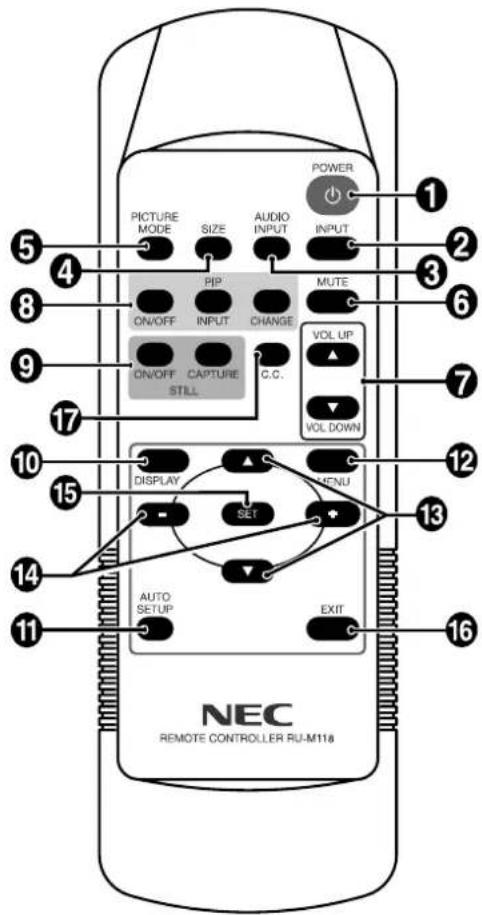
① POWER button
Switches the power on/off.
② INPUT button
Shows Input select menu for [DVI], [VGA], [RGB/HV], [HDMI], [DVD/HD], [S-VIDEO], [VIDEO1], [VIDEO2].
③ AUDIO INPUT button
Selects audio input source [AUDIO:1], [AUDIO:2], [AUDIO:3].
④ SIZE button
Selects picture size, [FULL], [NORMAL], [CUSTOM], [DYNAMIC] and [REAL]. See page 17.
⑤ PICTURE MODE button
Selects picture mode, [HIGHBRIGHT], [STANDARD], [sRGB], [CINEMA]. See page 17.
HIGHBRIGHT: for moving images such as DVD STANDARD: for images sRGB: for text based images CINEMA: for movies.
⑥ MUTE button
Turns on/off mute function.
⑦ VOLUME UP/DOWN button
Increase/decrease audio output level.
⑧ PIP (Picture In Picture) button
ON/OFF button: Toggle switches between PIP and POP (Picture Out Picture). See page 20.
INPUT button: Selects the "picture in picture" input signal. CHANGE button: Replaces to the main picture and sub picture.
NOTE: The "PIP" and "POP" modes do not function when the screen size is "CUSTOM" or "REAL".
| Sub picture | |||||||||
| DVI | VGA | RGB/HV | HDMI | DVD/HD | VIDEO1 | VIDEO2 | S-VIDEO | ||
| Main picture | DVI | - | √ | √ | - | √ | √ | √ | √ |
| VGA | √ | - | - | √ | √ | √ | - | √ | |
| RGB/HV | √ | - | - | √ | - | √ | - | √ | |
| HDMI | - | √ | √ | - | √ | √ | √ | √ | |
| DVD/HD | √ | √ | - | √ | - | √ | - | √ | |
| VIDEO1 | √ | √ | √ | √ | √ | - | - | - | |
| VIDEO2 | √ | - | - | √ | - | - | - | - | |
| S-VIDEO | √ | √ | √ | √ | √ | - | - | - | |

flowchart
graph LR
    A["PIP A_B"] --> B["POP A"]
    B --> C["SBS ASPECT A B"]
    C --> D["SBS FULL A B"]
    D --> E["OFF A"]
    E --> F["Feedback to A"]
⑨ STILL button
ON/OFF button: Activates/deactivates still picture mode. STILL CAPTURE button: Captures still picture.
⑩ DISPLAY button
Turns on/off the information OSD. See page 17.
⑪ AUTO SETUP button
Enters auto setup menu. See page 19.
⑫ MENU button
Turns on/off the menu mode.
⑬ UP/DOWN button
Acts as ▲▼ button to move the highlighted area up or down to select adjustment items within OSD menu. Small screen which adjusted "PIP" mode moves up or down.
14 MINUS/PLUS (-/+) button
Increases or decreases the adjustment level within OSD menu settings. Small screen which adjusted "PIP" mode moves left or right.
15 SET button
Makes selection.
16 EXIT button
Returns to previous menu within OSD menu.
⑰ C. C. button
Activates closed captioning. Note: VIDEO1, VIDEO2, S-VIDEO inputs only.
Operating Range for the Remote Control
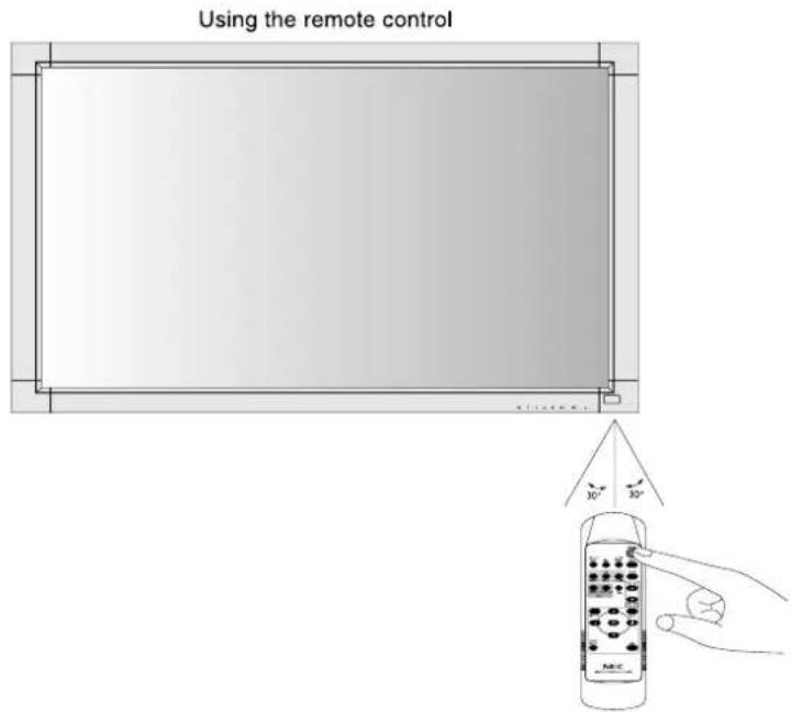
Point the top of the remote control toward the LCD monitor's remote sensor during button operation.
Use the remote control within a distance of about 7 m (23 ft.) from the front of the LCD monitor's remote control sensor or at a horizontal and vertical angle of within 30° within a distance of about 3.5 m (10 ft.)

Caution: Important, the remote control system may not function when direct sunlight or strong illumination strikes the remote control sensor of the LCD monitor, or when there is an object in the path.
Handling the remote control
• Do not subject to strong shock.
- Do not allow water or other liquid to splash the remote control. If the remote control gets wet, wipe it dry immediately.
- Avoid exposure to heat and steam.
- Other than to install the batteries, do not open the remote control.
1. Determine the installation location
CAUTION: Installing your LCD display must be done by a qualified technician. Contact your dealer for more information.
CAUTION: MOVING OR INSTALLING THE LCD MONITOR MUST BE DONE BY TWO OR MORE PEOPLE. Failure to follow this caution may result in injury if the LCD monitor falls.
CAUTION: Do not mount or operate the display upside down, face up, or face down.
CAUTION: This LCD has a temperature sensor and cooling fan. If the LCD becomes too hot, the cooling fan will turn on automatically. If the LCD becomes overheated while the cooling fan is running, a "Caution" warning will appear. If the "Caution" warning appears, discontinue use and allow the unit to cool. Using the cooling fan will reduce the likelihood of early circuit failure and may help reduce image degradation and "Image Persistence".
If the LCD is used in an enclosed area or if the LCD panel is covered with a protective screen, please check the inside temperature of the monitor by using the "HEAT STATUS" control in the OSD (see page 21). If the temperature is higher than the normal operating temperature, please turn the cooling fan to ON within the SCREEN SAVER menu within the OSD (see page 21).
IMPORTANT: Lay the protective sheet, which was wrapped around the LCD monitor when it was packaged, beneath the LCD monitor so as not to scratch the panel.
2. Install the remote control batteries
The remote control is powered by two 1.5V AAA batteries. To install or replace batteries:

A. Press and slide to open the cover.
B. Align the batteries according to the (+) and (−) indications inside the case.
C. Replace the cover.
CAUTION: Incorrect usage of batteries can result in leaks or bursting.
NEC recommends the following battery use:
- Place "AAA" size batteries matching the (+) and (-) signs on each battery to the (+) and (-) signs of the battery compartment.
• Do not mix battery brands. - Do not combine new and old batteries. This can shorten battery life or cause liquid leakage of batteries.
- Remove dead batteries immediately to prevent battery acid from leaking into the battery compartment.
- Do not touch exposed battery acid as it may injure skin.
NOTE: Remove the batteries if you do not intend to use the remote control for a long period of time.
3. Connect external equipment (See pages 14-15)
- To protect the external equipment; turn off the main power before making connections.
• Refer to your equipment user manual for further information.
4. Connect the supplied power cord
- The equipment should be installed close to an easily accessible power outlet.
- Fully insert the prongs into the power outlet socket. A loose connection may cause image degradation.
NOTE: Please refer to the "Safety Precautions and Maintenance" section of this manual for proper selection of AC power cord.

natural_image
Technical diagram showing a cable inserted into a mounted device with an attached power outlet (no text or symbols present)5. Switch on the power of all the attached external equipment
When connected with a computer, switch on the power of the computer first.
6. Operate the attached external equipment
Display the signal from the desired input source.
7. Adjust the sound
Make volume adjustments when required.
8. Adjust the screen (See pages 19 and 20)
Make adjustments to the screen display position when necessary.
9. Adjust the image (See page 19)
Make adjustments such as brightness or contrast when required.
10. Recommended Adjustments
To reduce the risk of the "Image Persistence", please adjust the following items based on the application being used: "POWER SAVE", "SCREEN SAVER" (See page 21), "SIDE BORDER COLOR" (See page 22), "DATE AND TIME", "SCHEDULE" (See page 20).
11. To prevent the main power switch from being changed
To prevent use of the main power switch, please attach the main switch cover, which is enclosed as an accessory.
NOTE: With the main power switch cover in place, the main power switch cannot be turned off. Remove main power switch cover in order to switch off the display.

NOTE: Do not connect/disconnect cables when turning on the monitor or other external equipment as this may result in a loss of the monitor image.
NOTE: Use an audio cable without a built-in resistor. Using an audio cable with a built-in resistor turns down the sound.
Before making connections:
* First, turn off the power of all attached equipment and make connections.
* Refer to the user manual included with each separate piece of equipment.
Wiring Diagram
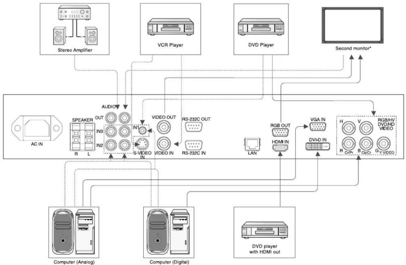
flowchart
graph TD
    A["AC IN"] --> B["SPEAKER"]
    B --> C["OUT"]
    B --> D["IN3"]
    B --> E["IN2"]
    B --> F["S-VIDEO IN"]
    F --> G["IN1"]
    G --> H["VIDEO OUT"]
    H --> I["RS-232C OUT"]
    H --> J["RS-232C IN"]
    J --> K["LAN"]
    K --> L["RGB OUT"]
    L --> M["HDMI IN"]
    M --> N["VGA IN"]
    N --> O["DVI-D IN"]
    O --> P["H"]
    P --> Q["V"]
    Q --> R["RGB/HV DVD/HD VIDEO"]
    P --> S["R Cr/Pr"]
    P --> T["B Cr/Cr"]
    P --> U["G Y VIDEO"]
    A --> V["Computer (Analog)"]
    A --> W["Computer (Digital)"]
    A --> X["DVD player with HDMI out"]
    A --> Y["Second monitor*"]
    Z["Stereo Amplifier"] --> AA["Audio"]
    AB["VCR Player"] --> AC["Video OUT"]
    AD["DVD Player"] --> AE["Video OUT"]
    AF["Computer"] --> AG["Computer (Analog)"]
    AH["Computer (Digital)"] --> AI["Computer (Digital)"]
    AJ["DVD player with HDMI out"] --> AK["Computer (Analog)"]
    AL["Second monitor*"] --> AM["Second monitor*"]
*: Multiple monitors that are daisy-chained have a limit to the connectable monitors.
| Connected equipment | Connecting terminal | Setting in Terminal Mode | Input signal name | Connecting Audio terminal |
| AV | DVI (DVI-D) | DVI MODE: DVI-HD | DVI | AUDIO IN1, IN2, IN3 |
| HDMI | RAW/EXPAND*1 | HDMI | HDMI | |
| DVD/HD (5BNC) | BNC MODE: COMPONENT | DVD/HD | AUDIO IN1, IN2, IN3 | |
| S-VIDEO | - | S-VIDEO | AUDIO IN1, IN2, IN3 | |
| VIDEO1 (BNC) | - | VIDEO1 | AUDIO IN1, IN2, IN3 | |
| VIDEO2 (5BNC) | BNC MODE: VIDEO | VIDEO2 | AUDIO IN1, IN2, IN3 | |
| PC | DVI (DVI-D) | DVI MODE: DVI-PC | DVI | AUDIO IN1, IN2, IN3 |
| VGA | - | VGA | AUDIO IN1, IN2, IN3 | |
| RGB/HV (5BNC) | BNC MODE: RGB | RGB/HV | AUDIO IN1, IN2, IN3 |
*1: depend on signal type.
- AUDIO IN 1, 2 and 3 can be used for audio input. To select audio source [IN1], [IN2] or [IN3] by pressing the AUDIO INPUT button (remote control).
Connecting a Personal Computer
Connecting your computer to your LCD monitor will enable you to display your computer's screen image. Some video cards with a pixel clock over 165 MHz may not display an image correctly. Your LCD monitor displays proper image by adjusting the factory preset timing signal automatically.
| Resolution | Scanning frequency | Remarks | ||
| Horizontal | Vertical | V321 | V421/V461 | |
| 640 x 480 | 31.5 kHz | 60 Hz | ||
| 800 x 600 | 37.9 kHz | 60 Hz | ||
| 1024 x 768 | 48.4 kHz | 60 Hz | ||
| 1280 x 768 | 48 kHz | 60 Hz | ||
| 1360 x 768 | 48 kHz | 60 Hz | Recommended resolution | |
| 1280 x 1024 | 64 kHz | 60 Hz | Compressed image | |
| 1600 x 1200 | 75 kHz | 60 Hz | Compressed image | Compressed image |
| 1920 x 1080 | 66.6 kHz | 60 Hz | Compressed image | Recommended resolution |
- If you use with a Macintosh PowerBook, set "Mirroring" to Off on your PowerBook.
Refer to your Macintosh's owner's manual for more information about your computer's video output requirements and any special identification or configuration your monitor's image and monitor may require.
• Input TMDS signals conforming to DVI standards.
• To maintain display quality, use a cable that conforms to DVI standards.
Connecting a DVD Player with HDMI out
- Please use an HDMI cable with HDMI logo.
• It may take a moment for the signal to appear.
• PC-DVI signals are not supported.
Power ON and OFF Modes
The LCD monitor power indicator will turn green while powered on and will turn red while powered off.
NOTE: The Main Power Switch must be in the ON position in order to power up the monitor using the remote control or the Power Button on the front of the LCD.


Power Indicator
| Status | |
| Power ON | Green |
| Power OFF | Red |
| Power Standby when “SCHEDULE” is enabled | Red On Green Blinking |
| Power Standby | Red, Green |
| Diagnosis (Detecting failure) | Red Blinking* See troubleshooting on page 29 |
Using Power Management
The LCD monitor follows the VESA approved DPM Power Management function.
The power management function is an energy saving function that automatically reduces the power consumption of the display when the keyboard or the mouse has not been used for a fixed period.
The power management feature on your new display has been set to the "ON" mode. This allows your display to enter a Power Saving Mode when no signal is applied. This could potentially increase the life and decrease the power consumption of the display.
NOTE: Depending on the PC and video card used, this function may not operate.
Selecting a video source
To view a video source:
Use the input button to set [HDMI], [VIDEO1], [VIDEO2] or [S-VIDEO].
Use the COLOR SYSTEM menu to set [AUTO], [PAL], [NTSC], [PAL60], [4.43NTSC], [SECAM], according to your video format.
Picture Size
DVI, VGA, RGB/HV

HDMI, DVD/HD, S-VIDEO, VIDEO1, VIDEO2

| Aspect ratio of image | Unchanged view*1 | Recommended selection for picture size*1 |
| 4:3 |  | NORMAL  |
DYNAMIC  | ||
| Squeeze | 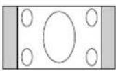 | FULL |
*1 Grey areas indicate unused portions of the screen.
NORMAL: Displays the aspect ratio the same as it is sent from the source.
FULL: Fills entire screen.
DYNAMIC: Expands a 4:3 pictures to fill the entire screen with non-linearity. Some of the outside image area will be cut off due to expansion.
CUSTOM (ZOOM)
The image can be expanded beyond the active display area. The image which is outside of active display area is not shown.

REAL: Image will be displayed 1 by 1 pixel.
Picture Mode
DVI, VGA, RGB/HV
STANDARD → sRGB → HIGHBRIGHT
HDMI, DVD/HD, S-VIDEO, VIDEO1, VIDEO2
STANDARD → CINEMA → HIGHBRIGHT
Information OSD
DVI, VGA, RGB/HV

DVD/HD
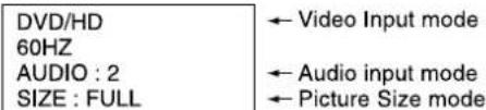
VIDEO

PIP or POP
Main: VGA
Sub: S-VIDEO
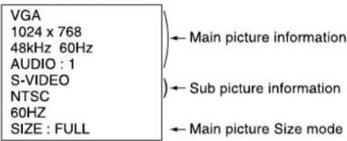
OSD (On-Screen-Display) Controls
Remote Control
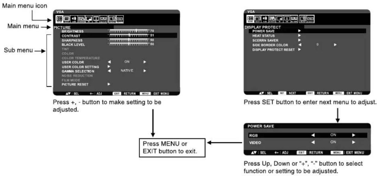
Press MENU button to open Main menu.
Press "+", "-" button to select Main menu, and press Up, Down button to enter Sub menu.
Press SET Button to enter next menu to adjust.
Press Up, Down or "+",-" button to select function, or setting to be adjusted.
Press MENU or EXIT button to exit.

flowchart
graph LR
    A["Menu"] --> B["SET"]
    B --> C["SET"]
    C --> D["SET"]
    D --> E["SET"]
    E --> F["SET"]
    F --> G["SET"]
    G --> H["EXIT"]
    I["OR"] --> J["Press +, - button to make setting to be adjusted."]
Control Panel
Press EXIT button to open Main menu and press "+" , "-" button to select Main menu. Then press Up, Down button to enter Sub menu.
Press INPUT button to enter next menu to adjust.
Press Up, Down or "+" button to select function, or setting to be adjusted.
Press EXIT button to exit.

flowchart
graph TD
    A["EXIT button Then, “+”, “-”, Up, Down button"] --> B["OR"]
    B --> C["INPUT button"]
    C --> D["Press +, - button to make setting to be adjusted."]
    D --> E["UP, Down or “+”, “-” button"]
    E --> F["EXIT button"]
OSD screen
Press MENU button to open Main menu. Press +, - button to select Main menu. Press down or up to enter Sub menu.
flowchart
graph TD
    A["Main menu icon"] --> B["VGA"]
    C["Main menu"] --> D["PICTURE"]
    E["Sub menu"] --> F["COLOR TEMPERATURE"]
    G["Press +,- button to make setting to be adjusted."] --> H["PRESS MENU or EXIT button to exit."]
    I["Press SET button to enter next menu to adjust."] --> J["POWER SAVE"]
    K["Press Up, Down or "+" -" button to select function or setting to be adjusted."] --> L["POWER SAVE"]
Setting
| PICTURE | ||
| BRIGHTNESS | Adjusts the overall image and background brightness. | |
| CONTRAST | Adjusts the image brightness in relation to the input signal.NOTE: sRGB picture mode is standard and cannot be changed. | |
| SHARPNESS | Adjusts the crispness of the image. | |
| BLACK LEVEL | Adjusts the image brightness in relation to the background. | |
| TINTINPUT HDMI, DVD/HD, -VIDEO, VIDEO1, VIDEO2 only | Adjusts the tint of the screen. | |
| COLORINPUT HDMI, DVD/HD,-VIDEO, VIDEO1, VIDEO2 only | Adjusts the color depth of the screen. | |
| COLOR TEMPERATURE | Adjusts the color temperature of the entire screen. A low color temperature will make the screen reddish.A high color temperature will make the screen bluish. | |
| USER COLOR | Select the USER COLOR SETTING feature ON/OFF. | |
| USER COLOR SETTING | Adjusts the levels of the Red, Yellow, Green, Cyan, Blue and Magenta.Note: The sRGB picture mode is standard and cannot be changed.It can be adjusted only when USER COLOR is selected ON. | |
| GAMMA SELECTION | Select a display gamma for best picture quality. | |
| NATIVE | Gamma correction is handled by the LCD panel. | |
| 2.2 | Typical display gamma for use with a PC. | |
| 2.4 | Good for video (TV, DVD, etc.) | |
| S GAMMA | Special gamma for certain types of movies. Raises the dark parts and lowers the light parts of the image.NOTE: sRGB picture is standard and cannot be changed. | |
| NOISE REDUCTIONINPUT S-VIDEO, VIDEO1, VIDEO2 only | Adjusts the amount of noise reduction. | |
| FILM MODEINPUT HDMI, DVD/HD, S-VIDEO, VIDEO1, VIDEO2 only | Selects Film mode function. (AUTO)This mode is better suited for movies, which is converted 24 Frames/sec source to DVD Video. | |
| PICTURE RESET | Resets the all settings within the PICTURE menu back to factory setting. | |
| ADJUST | ||
| AUTO SETUPINPUT VGA, RGB/HV only | Press "SET" button to automatically adjust screen size, horizontal position, vertical position, clock, clock phase, white level and black level. | |
| AUTO ADJUSTINPUT VGA, RGB/HV only | Selecting ON when changing the timing, the horizontal position, vertical position and clock phase will adjust automatically. | |
| H POSITIONALL inputs except DVI, HDMI | Controls the horizontal position of the image within the Display area of the LCD.Press + to move right. Press - to move left. | |
| V POSITIONALL inputs except DVI, HDMI | Controls the vertical position of the image within the Display area of the LCD.Press + to move up. Press - to move down. | |
| CLOCKINPUT VGA, RGB/HV only | Press + to expand the width of the image on the right of the screen.Press - to narrow the width of the image on the left. | |
| CLOCK PHASEINPUT VGA, RGB/HV only | Adjusts the visual "noise" on the image. | |
| ZOOM MODE | You can select "FULL", "NORMAL", "DYNAMIC", "CUSTOM" and "REAL".NOTE: DYNAMIC is INPUT HDMI, DVD/HD, S-VIDEO, VIDEO1, VIDEO2 only.Selecting DYNAMIC expands 4:3 picture to fill the screen. Some of the image is lost due to expansion.Selecting "REAL" image will be displayed 1 by 1pixel. | |
| CUSTOM ZOOM | "CUSTOM ZOOM" will be selected when you select "CUSTOM" on the screen "ZOOM" mode. | |
| ZOOM | Expands the horizontal and the vertical size simultaneously. | |
| H ZOOM | Expands the horizontal size only. | |
| V ZOOM | Expands the vertical size only. | |
| H POSITION | Moves to the right with + button. Moves to the left with - button. | |
| V POSITION | Moves up with + button. Moves down with - button. | |
| H RESOLUTIONINPUT VGA, RGB/HV only | Adjusts the horizontal size of the image.Press + button to expand, and press - button to narrow the width of the image on the screen. | |
| V RESOLUTIONINPUT VGA, RGB/HV only | Adjusts the vertical size of the image.Press + button to expand, and press - button to narrow the width of the image on the screen. | |
| INPUT RESOLUTIONINPUT VGA, RGB/HV only | Selects to decision of input signal timings 1024x768, 1280x768, 1360x768 and 1366x768 if there is a detection problem. If no problem is detected, the only available option will be "AUTO". | |
| ADJUST RESET | Resets the all settings within the ADJUST menu back to factory setting. | |
| AUDIO | ||
| BALANCE | Adjust the balance of L/R volume. | |
| TREBLE | To accentuate or reduce the high frequency sound. Press + to increase, press - to decrease. | |
| BASS | To accentuate or reduce the low frequency sound. Press + to increase, press - to decrease. | |
| AUDIO RESET | Resets the all settings within the AUDIO menu back to factory setting. | |
| SCHEDULE | ||
| OFF TIMER | Sets the monitor to power off after a length of time.A time between 1 to 24 hours is available. | |
| SCHEDULE | Creates a working schedule for the monitor to use.(See "NOTE 1" on page 23 for further information). | |
| DATE AND TIME | Sets the date, time, and daylight saving region.Setting item: YEAR/MONTH/DAY/HOUR/MINUTE/DAYLIGHT SAVING TIMEDate & time must be set in order for the "SCHEDULE" function to operate. | |
| SCHEDULE RESET | Resets the all settings within the SCHEDULE menu back to factory setting except DATE AND TIME setting. | |
| PIP | ||
| PIP MODE | Selects Picture-in-Picture mode. See page 10. | |
| OFF | Normal mode. | |
| PIP | Picture in Picture mode. | |
| POP | Picture out picture mode. | |
| SBS ASPECT | Side by side (split screen) mode, with keep aspect. | |
| SBS FULL | Side by side (split screen) mode, with full screen. | |
| PIP SIZE | Selects the size of sub-picture used in "Picture-in-Picture" (PIP) mode."LARGE", "MIDDLE" and "SMALL" are available. | |
| PIP AUDIO | Selects the sound source in PIP mode. | |
| PIP H-POSITION | Determines where the PIP appears on the screen. | |
| PIP V-POSITION | Determines where the PIP appears on the screen. | |
| TEXT TICKER | ||
| MODE | Enables Text Ticker and allows you to set Horizontal or Vertical direction. | |
| POSITION-H | Selects the horizontal location of the Text Ticker on the screen. | |
| POSITION-V | Selects the vertical location of the Text Ticker on the screen. | |
| SIZE | Determines the size of the Text Ticker in relationship to the overall screen size. | |
| BLEND | Sets the transparency of the Text Ticker (10: transparent, 100: opaque). | |
| DETECT | Enables auto-detection of the Text Ticker. | |
| FADE IN | Enables fade-in of the text ticker when DETECT is AUTO. | |
| SUB INPUT | Selects sub picture input signal. | |
| PIP RESET | Resets the all settings within the PIP menu back to factory setting. | |
| OSD | ||
| LANGUAGE | Selects the language used by the OSD from seven languages.ENGLISH/DEUTSCH/FRANÇAIS/ESPAÑOL/ITALIANO/SVENSKA/日本語 | |
| OSD TURN OFF | Turns off the OSD after a period of inactivity. The preset choices are 5 - 120 seconds. | |
| OSD H-POSITION | Adjusts the horizontal position of the OSD menu. | |
| OSD V-POSITION | Adjusts the vertical position of the OSD menu. | |
| INFORMATION OSD | Selects the information OSD displays or not. The information OSD will display when input signal or source change or warning message like as no-signal or out-of range.A time between 1 to 10 seconds is available. | |
| MONITOR INFORMATION | Indicates the model and serial number of your monitor. | |
| CLOSED CAPTIONINPUT DVD/HD, S-VIDEO, VIDEO1, VIDEO2 only | Activates closed captioning. | |
| OSD RESET | Resets the all settings within the OSD menu back to factory setting. | |
| MULTI DISPLAY | ||
| MONITOR ID | Sets the monitor ID number from 1-26. Monitor ID is used for RS-232C control only. | |
| IR CONTROL | Selects the infrared wireless remote controller mode.The item in this menu will become effective by pressing "SET" button on the selected item. | |
| NORMAL | The monitor will be controlled normally by wireless remote controller. | |
| LOCK | Disables the monitor control by infrared wireless remote controller.Keep pressing "DISPLAY" button during 5 sec or more, this setting will return to "NORMAL". | |
| TILE MATRIX | Allows one image to be expanded and displayed over multiple screens (up to 16) through a distribution amplifier. When screen size is "Real", this function does not operate. | |
| H MONITORS | Selects number of monitors arranged vertically. | |
| V MONITORS | Selects number of monitors arranged horizontally. | |
| POSITION | Selects which section of the tiled image to be displayed on the monitor. | |
| TILE COMP | Turns the TILE COMP feature on. | |
| ENABLE | Enables the Tile Matrix.PIP and STILL will be disabled when "TILE MATRIX" is activated. | |
| POWER ON DELAY | Adjusts the delay time between being in "standby" mode and entering "power on" mode."POWER ON DELAY" time is selectable from OFF, 2, 4, 6, 8, 10, 20, 30, 40 and 50 sec. | |
| EXTERNAL CONTROL | ||
| CONTROL | Selects the control interface, RS-232C or LAN. | |
| LAN RESET | Resets the LAN settings. | |
| MULTI DISPLAY RESET | Resets the all settings within the MULTI DISPLAY menu back to factory setting. | |
| DISPLAY PROTECTION | ||
| POWER SAVE | Sets how long the monitor waits to go into power save mode after a lost signal.Note: When connecting DVI, video card might not stop sending digital data even if image has disappeared.In this case the monitor does not get to power management mode. | |
| RGB | Selecting "ON", the monitor will go to power management mode when DVI, VGA, RGB/HV sync is lost. | |
| VIDEO | Selecting "ON", the monitor will go to power management mode after about 10 minutes when DVD/HD and HDMI, S-VIDEO, VIDEO1, VIDEO2 input signal is lost. | |
| HEAT STATUS | Information of status for COOLING FAN, BRIGHTNESS and TEMPERATURE. COOLING FAN runs when inside temperature is over a guaranteed limit. In this case warning is displayed on the screen. | |
| SCREEN SAVER | Use the SCREEN SAVER function to reduce the risk of Image Persistence.(See "NOTE 2" on page 23 for further information). | |
| GAMMA | The display gamma is changed and fixed when "ON" is selected. | |
| COOLING FAN | The built in cooling fan is always on when set "ON". | |
| BRIGHTNESS | The brightness is decreased when "ON" is selected. | |
| MOTION | Image is slightly expanded and moves 4 directions (UP, DOWN, RIGHT, LEFT) periodically (Need setting the time for movement).Movement area is approximately +/- 10 mm from original position;Please locate the important information such as text within 90% area of screen image.PIP and STILL will be disabled when "MOTION" is active. | |
| SIDE BORDER COLOR | Adjusts the color of the side borders when a 4:3 image is displayed.Press + button, the bar will become lighter.Press - button, the bar will become darker. | |
| DISPLAY PROTECTION RESET | Resets the all settings within the DISPLAY PROTECTION menu back to factory setting. | |
| ADVANCED OPTION | ||
| INPUT CHANGE | Sets input change speed.NOTE: When “QUICK” is selected, picture may be distorted when signal input is changed.This function should be chosen after all adjustment options have been made for the input. | |
| TERMINAL SETTING | ||
| DVI MODE | Selects the kind of DVI-D equipment which is connected to the DVI input. Select “DVI-PC” when PC or other computer equipment is connected. Select “DVI-HD” when DVD player, which has DVI-D output, is connected. | |
| BNC MODE | Selects the kind of equipment which is connected to the BNC input.RGB: Analog input (R, G, B, H, V)COMPONENT: Component (Cr/Pr, Cb/Pb, Y)VIDEO: Composite video (VIDEO2) | |
| HDMI SIGNAL | RAW: Disable the expanded feature.EXPAND: Expand image contrast and increase detail in the dark and bright areas. | |
| SCAN CONVERSION INPUT HDMI, DVDHD, S-VIDEO, VIDEO1, VIDEO2 only | Selects IP (Interlace to Progressive) converter function. | |
| PROGRESSIVE | Enables the IP function, to convert interlace signal to progressive. Normally use this. | |
| INTERLACE | Disables the IP function.NOTE: This mode is better suited for motion pictures, but it is in danger of image retention. | |
| COLOR SYSTEM INPUT S-VIDEO, VIDEO1, VIDEO2 only | Selects color system depend on your video format of the input signal.(AUTO/PAL/NTSC/PAL60/4.43NTSC/SECAM)AUTO: Selects color system setting automatically base on input signal. | |
| SCAN MODE INPUT DVDHD, HDMI S-VIDEO, VIDEO1, VIDEO2 only | Changes the display area of the image. | |
| OVER SCAN | Set to display area about 95% | |
| UNDER SCAN | Set to display area about 100% | |
| ADVANCED OPTION RESET | Resets the all settings within the ADVANCED OPTION menu back to factory setting. | |
| FACTORY RESET | Selecting “YES” allows you to reset PICTURE, ADJUST, AUDIO, PIP, OSD, MULTI DISPLAY, DISPLAY PROTECTION and ADVANCED OPTION will be back to factory settings (except LANGUAGE, DATE AND TIME and BNC MODE).Select “YES” and press “SET” button to restore the factory preset data.Press “EXIT” button to cancel and return the previous menu. | |
NOTE 1: CREATING A SCHEDULE
Using the "SCHEDULE" function allows you to set up to seven different scheduled time intervals when the LCD Monitor will be activated. You can select the time the monitor turns on and turns off, the day of week the monitor is activated, and which input source the monitor will use for each scheduled activation period. A check mark in the box next to the number of the schedule indicates that the selected schedule is in effect.
To select which schedule to set, use the up/down arrows to move the number (1 to 7) of the schedule.
Use the (+) and (-) buttons to move the cursor horizontally within the particular schedule. The "SET" button is used to make a selection.
If you create a schedule but do not want to use a power on time, select "--" in the "ON" time slot.
If you do not want to use a power off time select "--" in the OFF time slot.
If there is no input selected ("--" showing in the input spot) the input from the previous schedule will be used.
The selection of EVERY DAY within a schedule takes priority over other schedules that are set up to operate weekly.
After the schedule is programmed, press the "MENU" button to close the OSD and make the set schedule available.
When schedules are overlapping, scheduled Power ON time has priority over scheduled Power OFF time.
Note: If schedules are overlapping then the schedule with the highest number will have priority over the schedule with the lowest number. For example schedule #7 will have priority over schedule #1.
ON time should be earlier than OFF time. If OFF time is earlier than ON time, schedule function is not working properly.
If you would like to set the monitor power on at 23:00 and power off at 6:00 next morning, you should set 2 settings. First setting is ON time is "23:00" and OFF time is "--", next setting is ON time is "--" and OFF time is "06:00".
NOTE 2: IMAGE PERSISTENCE
Please be aware that LCD Technology may experience a phenomenon known as Image Persistence. Image Persistence occurs when a residual or "ghost" image of a previous image remains visible on the screen. Unlike CRT monitors, LCD monitors' image persistence is not permanent, but constant images being displayed for a long period of time should be avoided.
To alleviate image persistence, turn off the monitor for as long as the previous image was displayed. For example, if an image was on the monitor for one hour and a residual image remains, the monitor should be turned off for one hour to erase the image.
As with all personal display devices, NEC DISPLAY SOLUTIONS recommends displaying moving images and using a moving screen saver at regular intervals whenever the screen is idle or turning off the monitor when not in use.
Please set "SCREEN SAVER", "DATE AND TIME" and "SCHEDULE" functions to further reduce the risk of Image persistence.
For long life use as Public Display
< Image Sticking of LCD Panel >
When an LCD panel is operated continuously for long hours, a trace of electric charge remains near the electrode inside LCD, and residual or "ghost" image of previous image may be observed. (Image Persistence)
Image Persistence is not permanent, but when fixed image is displayed for long period, ionic impurities inside LCD are accumulated along the displayed image, and may be permanent. (Image Sticking)
To prevent Image Sticking, and for longer life usage of LCD, the following are recommended.
- Fixed image should not be displayed for long period. Change fixed images after short intervals.
- When not in use, please turn off the monitor by remote control, or use Power Management or use Schedule Functions.
- Lower environmental temperatures prolong the lifespan of the monitor.
When Protective surface (glass, acrylic) is installed over the LCD surface, the LCD surface is located in an enclosed space, the monitor are stacked, utilize the temperature sensors inside monitor.
To reduce the environmental temperature, use the Cooling Fan, Screen Saver and Low Brightness.
- Please use "Screen Saver Mode" of monitor.
Controlling the LCD monitor via RS-232C Remote Control
This LCD monitor can be controlled by connecting a personal computer with a RS-232C terminal.
Functions that can be controlled by a personal computer are:
• Power ON or OFF
• Switching between input signals
Connection
LCD Monitor + PC

flowchart
graph TD
    A["Monitor + PC"] --> B["MultiSync"]
    B --> C["PC (Out)"]
    C --> D["RS-232C Cable"]
    D --> E["RS-232C (IN)"]
    E --> F["RS-232C (OUT)"]
    F --> G["RS-232C (IN)"]
    G --> H["RS-232C (OUT)"]
    H --> I["MultiSync"]
    B --> J["OUT"]
    B --> K["IN"]
NOTE: If your PC is equipped only with a 25-pin serial port connector, a 25-pin serial port adapter is required. Contact your dealer for details.
* In order to function, the RS-232C OUT terminal can only be connected to another monitor of the same model. Do not connect to other types of equipment.
To control monitor or multiple monitors that are daisy-chained together please use the control command. Instructions for the control command can be found on the CD included with the display. The file is called "External_control_****.pdf".
1) Interface
| PROTOCOL | RS-232C |
| BAUD RATE | 9600 [bps] |
| DATA LENGTH | 8 [bits] |
| PARITY BIT | NONE |
| STOP BIT | 1 [bit] |
| FLOW CONTROL | NONE |
This LCD monitor uses RXD, TXD and GND lines for RS-232C control.
The reverse type cable (null modem cable) (not include) should be used for RS-232C control.
2) Control command diagram
Please see file "External_Control_****.pdf" on the CD-ROM.
Connecting to a Network
Using a LAN cable allows you to specify the Network Settings and the Alert Mail Settings by using an HTTP server function.
NOTE: When you use this function, EXTERNAL CONTROL should be "LAN" (See page 21).
To use a LAN connection, you are required to assign an IP address.
Example of LAN connection:

flowchart
graph TD
    Server["Server"] --> Hub["Hub"]
    Hub --> LAN_cable["LAN cable (not supplied)"]
    LAN_cable --> Device1["Device 1"]
    LAN_cable --> Device2["Device 2"]
    LAN_cable --> Device3["Device 3"]
    LAN_cable --> Device4["Device 4"]
    Device1 --> Device5["Device 5"]
    Device2 --> Device6["Device 6"]
    Device3 --> Device7["Device 7"]
    Device4 --> Device8["Device 8"]
    Note["NOTE: Use a category 5 or higher LAN cable."]
Network Setting by Using an HTTP Browser
Overview
Connecting the monitor to a network allows for monitor control from a computer via the network.
To perform the monitor control from a web browser, you must have an exclusive application installed on your computer.
The IP address and subnet mask of the monitor can be set on the Network Setting screen of the web browser by using an HTTP server function. Please be sure to use "Microsoft Internet Explorer 6.0" or a higher version for the web browser. (This device uses "JavaScript" and "Cookies" and the browser should be set to accept these functions. The setting method will vary depending on the version of browser. Please refer to the help files and the other information provided in your software.)
Access is gained to the HTTP server function by starting the Web browser on the computer via the network connected to the monitor and entering the following URL.
Network Setting
http://
TIP: The default IP address is "192.168.0.10".
The exclusive application can be downloaded from our website.
NOTE: If the MONITOR NETWORK SETTINGS screen does not appear in the web browser, press the Ctrl+F5 keys to refresh your web browser (or clear the cache).
The display or button's response can be slowed down or operation may not be accepted depending the settings of your network.
Should this happen, consult your network administrator.
The LCD monitor may not respond if its buttons are repeatedly pressed in rapid intervals. Should this happen, wait a moment and repeat.
If you still can't get a response, turn off and back on the monitor.
Preparation Before Use
Connect the monitor to a commercially available LAN cable before engaging in browser operations.
Operation with a browser that uses a proxy server may not be possible depending on the type of proxy server and the setting method. Although the type of proxy server will be a factor, it is possible that items that have actually been set will not be displayed depending on the effectiveness of the cache, and the contents set from the browser may not be reflected in operation. It is recommended that a proxy server not be used unless it is unavailable.
Handling of the Address for Operation via a Browser
Regarding the actual address that is entered for the address or entered into the URL column when operation of the monitor is via a browser, the host name can be used as it is when the host name corresponding to the IP address of the monitor has been registered to the domain name server by a network administrator, or the host name corresponding to the IP address of the monitor has been set in the "HOSTS" file of the computer being used.
Example 1: When the host name of the monitor has been set to "pd.nec.co.jp", access is gained to the network setting by specifying http://pd.nec.co.jp/index.html for the address or the entry column of the URL.
Example 2: When the IP address of the monitor is "192.168.73.1", access is gained to the mail alert settings by specifying http://192.168.73.1/index.html for the address or the entry column of the URL.
Network Settings
http://
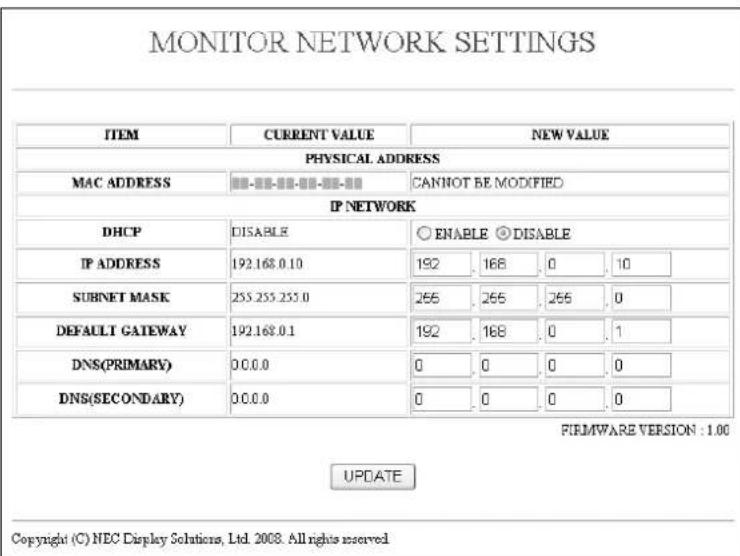
| DHCP | Enabling this option automatically assigns an IP address to the monitor from your DHCP server. Disabling this option allows you to register the IP address or subnet mask number obtained from your network administrator.NOTE: The IP address of the monitor is required to change the network setting.The IP address will not be displayed on the Monitor's menu.Consult your network administrator for the IP address when [ENABLE] is selected for [DHCP]. |
| IP ADDRESS | Set your IP address of the network connected to the monitor when [DISABLE] is selected for [DHCP]. |
| SUBNET MASK | Set your subnet mask number of the network connected to the monitor when [DISABLE] is selected for [DHCP]. |
| DEFAULT GATEWAY | Set your default gateway of the network connected to the monitor when [DISABLE] is selected for [DHCP]. |
| DNS (PRIMARY) | Set your primary DNS settings of the network connected to the monitor. |
| DNS (SECONDARY) | Set your secondary DNS settings of the network connected to the monitor. |
| UPDATE | Reflect your settings.NOTE: Close the browser after clicking [UPDATE].The monitor will automatically update your settings. |
Alert Mail Setting
http://
MONITOR NETWORK SETTINGS

APPLY

Copyright (C) NEC Display Solutions, Ltd. 2008. All rights reserved.
This option notifies your computer of an error message via e-mail when using wired LAN. An error message notification will be sent when an error occurs in the monitor.
| HOST NAME | Type in the hostname of the network connected to the monitor.Up to 60 alphanumeric characters can be used. |
| DOMAIN NAME | Type in the domain name of the network connected to the monitor.Up to 60 alphanumeric characters can be used. |
| ALERT MAIL | Checking [ENABLE] will turn on the Alert Mail feature.Checking [DISABLE] will turn off the Alert Mail feature. |
| SENDER'S ADDRESS | Type in the senders address. Up to 60 alphanumeric and symbols characters can be used. |
| SMTP SERVER NAME | Type in the SMTP server name to be connected to the monitor.Up to 60 alphanumeric characters can be used. |
| RECIPIENT'S ADDRESS 1 to 3 | Type in your recipient's address. Up to 60 alphanumeric and symbols characters can be used. |
| APPLY | Click this button to reflect the above settings. |
| EXECUTE | Click this button to send a test mail to check if your settings are correct. |
| STATUS | A reply to a test mail will be displayed. |
NOTE: • If you execute a test, you may not receive an Alert mail.
Should this happen, check if the network settings are correct.
- If you entered an incorrect address in a test, you may not receive an Alert mail.
Should this happen, check if the Recipient's Address is correct.
TIP: The Alert Mail settings will not be affected even when [RESET] is done from the menu.
For Control command diagram, please see file "External_Control.pdf" on the CD-ROM.
Reduced Footprint: Provides the ideal solution for environments requiring superior image quality but with size and weight limitations.
Color Control Systems: Allows you to adjust the colors on your screen and customize the color accuracy of your monitor to a variety of standards.
sRGB Color Control: A new optimized color management standard which allows for color matching on computer displays and other peripherals. The sRGB standard, which is based on a calibrated color space, allows for optimal color representation and backward compatibility with other common color standards.
OSD (On-Screen-Display) Controls: Allow you to quickly and easily adjust all elements of your screen image via simple to use on-screen menus.
Plug and Play: The Microsoft® solution with the Windows® operating system facilitates setup and installation by allowing the monitor to send its capabilities (such as screen size and resolutions supported) directly to your computer, automatically optimizing display performance.
IPM (Intelligent Power Manager) System: Provides innovative power-saving methods that allow the monitor to shift to a lower power consumption level when on but not in use, saving two-thirds of your monitor energy costs, reducing emissions and lowering the air conditioning costs of the workplace.
FullScan Capability: Allows you to use the entire screen area in most resolutions, significantly expanding image size.
VESA Standard (FDMIv1) Mounting Interface: Allows users to connect their LCD monitor to any VESA standard (FDMIv1) third party mounting arm or bracket. Allows for the monitor to be mounted on a wall or an arm using any third party compliant device. NEC recommends using mounting interface that comply with TÜV-GS and/or UL1678 standard in North America.
DVI-D: The digital-only subset of DVI ratified by the Digital Display Working Group (DDWG) for digital connections between computers and displays. As a digital-only connector, analog support is not provided for a DVI-D connector. As a DVI-based digital only connection, only a simple adapter is necessary for compatibility between DVI-D and other DVI-based digital connectors such as DFP and P&D. The DVI interface of this display supports HDCP.
TILE MATRIX, TILE COMP: Shows one image over multiple screens with accuracy while compensating for bezel width.
ZOOM: Expands image size for horizontal and vertical direction.
Self-diagnosis: If an internal error should occur, a failure state will be indicated.
No picture
- The signal cable should be completely connected to the display card/computer.
• The display card should be completely seated in its slot. - Front Power Switch and computer power switch should be in the ON position.
- Check to make sure that a supported mode has been selected on the display card or system being used. (Please consult display card or system manual to change graphics mode.)
- Check the monitor and your display card with respect to compatibility and recommended settings.
- Check the signal cable connector for bent or pushed-in pins.
Power Button does not respond
- Unplug the power cord of the monitor from the AC outlet to turn off and reset the monitor.
Image persistence
- Please be aware that LCD Technology may experience a phenomenon known as Image Persistence. Image Persistence occurs when a residual or "ghost" image of a previous image remains visible on the screen. Unlike CRT monitors, LCD monitors' image persistence is not permanent, but constant images being displayed for a long period of time should be avoided. To alleviate image persistence, turn off the monitor for as long as the previous image was displayed. For example, if an image was on the monitor for one hour and a residual image remains, the monitor should be turned off for one hour to erase the image.
NOTE: As with all personal display devices, NEC DISPLAY SOLUTIONS recommends displaying moving images and using a moving screen saver at regular intervals whenever the screen is idle or turning off the monitor when not in use.
Image is unstable, unfocused or swimming is apparent
- Signal cable should be completely attached to the computer.
- Use the OSD Image Adjust controls to focus and adjust display by increasing or decreasing the fine adjustment. When the display mode is changed, the OSD Image Adjust settings may need to be re-adjusted.
- Check the monitor and your display card with respect to compatibility and recommended signal timings.
- If your text is garbled, change the video mode to non-interlace and use 60Hz refresh rate.
Image of component signal is greenish
- Check to see if the DVD/HD input connector is selected.
LED on monitor is not lit
(no green or red color can be seen)
• Power Switch should be in the ON position and power cord should be connected.
• Make certain the computer is not in a power-saving mode (touch the keyboard or mouse).
RED LED on monitor is blinking
- A certain failure might have occurred, please contact your nearest authorized NEC DISPLAY SOLUTIONS service facility.
Display image is not sized properly
- Use the OSD Image Adjust controls to increase or decrease the coarse adjustment.
- Check to make sure that a supported mode has been selected on the display card or system being used. (Please consult display card or system manual to change graphics mode.)
Selected resolution is not displayed properly
- Use OSD Display Mode to enter Information menu and confirm that the appropriate resolution has been selected. If not, select corresponding option.
No Sound
- Check to see if speaker cable is properly connected.
• Check to see if mute is activated. - Check to see if volume is set at minimum.
Remote Control is not available
- Check the Remote Control's batteries status.
- Check if batteries are inserted correctly.
- Check if the Remote Control is pointing at the monitor's remote sensor.
- Check the Remote Control (IR Control) Mode status.
- The remote control system may not function when direct sunlight or strong illumination strikes the remote control sensor of the LCD monitor, or when there is an object in the path.
"SCHEDULE"/"OFF TIMER" function is not working properly
- The "SCHEDULE" function will be disabled when the "OFF TIMER" is set.
- If the "OFF TIMER" function is enabled and the power to the LCD monitor is turned off when the power supply is interrupted unexpectedly, then the "OFF TIMER" will be reset.
RS-232C or LAN control is not available
- Check RS-232C or LAN cable connection.
- Check "CONTROL" setting in "EXTERNAL CONTROL".
Product Specifications
| LCD Module | 32"/80.0 cm diagonal | ||
| Pixel Pitch: | 0.511 mm | ||
| Resolution: | 1366 x 768 dots | ||
| Color: | Over 16 million colors (depending on video card used) | ||
| Brightness: | 450 cd/m2 (Max.) | ||
| Contrast Ratio: | 3000:1 | ||
| Viewing Angle: | 89° (typ) @ CR>10 | ||
| Design View Distance: | 875 mm | ||
| Frequency Horizontal: | 15.625/15.734 kHz, 31.5 kHz - 91.1 kHz | ||
| Vertical: | 50.0 - 85.0 Hz | ||
| Pixel Clock | 25.0 MHz - 165.0 MHz | ||
| Viewable Size | 697.7 x 392.3 mm | ||
| Input Signal | |||
| DVI | DVI-D 24pin | Digital RGB | DVI (HDCP)VGA60, SVGA60, XGA60, WXGA60, SXGA60*, UXGA60*, 1920 x 1080*1 (60Hz) |
| VGA | 15pin Mini D-sub | Analog RGB | 0.7 Vp-p/75 ohmVGA60, SVGA60, XGA60, WXGA60, SXGA60*, UXGA60*, 1920 x 1080*1 (60Hz) |
| Sync | Separate: TTL level (Pos./Neg.) | ||
| RGB/HV*2 | BNC (R,G,B,H,V) | Analog RGB | 0.7 Vp-p/75 ohmVGA60, SVGA60, XGA60, WXGA60, SXGA60*, UXGA60*, 1920 x 1080*1 (60Hz) |
| Sync | Separate: TTL level (Pos./Neg.) | ||
| HDMI | HDMI Connector | Digital RGB | HDMI1080p, 1080i, 720p@50Hz/60Hz, 576p@50Hz, 480p@60Hz |
| DVD/HD*2 | BNC (Y, Cb/Pb, Cr/Pr) | Component | Y: 1.0 Vp-p/75ohm, Cb/Cr (Pb/Pr): 0.7 Vp-p/75 ohmHDTV/DVD: 1080i@60Hz*, 1080p@60Hz*, 720p@50Hz/60Hz, 576p@50Hz, 480p@60Hz, 576i@50Hz, 480i@60Hz |
| S-VIDEO | Mini DIN 4 pin | S-VIDEO | Y: 1.0 Vp-p/75 ohm C: 0.286 Vp-p/75 ohm (NTSC), 0.3 Vp-p/75 ohm (PAL/SECAM)NTSC/PAL/SECAM/4.43NTSC/PAL60 |
| VIDEO1VIDEO2*2 | BNCBNC | Composite | 1.0 Vp-p/75 ohmNTSC/PAL/SECAM/4.43NTSC/PAL60 |
| Output Signal | |||
| RGB | 15pin Mini D-sub | Analog RGB | 0.7 Vp-p with 75 ohm terminatedSeparate HV sync: TTL level (Pos. / Neg.) |
| VIDEO | BNC | Composite | 1.0 Vp-p with 75 ohm terminated |
| AUDIO | |||
| AUDIO Input | RCA (L/R) X2STEREO Mini Jack | Analog Audio | Stereo L/R 0.5 Vrms |
| AUDIO Output | RCA (L/R) | Analog Audio | Stereo L/R 0.5 Vrms |
| Speaker Output | External Speaker Jack 7 W + 7 W (8 ohm) | ||
| ControlRS-232C In:9 Pin D-subRS-232C Out:9 Pin D-sub (with daisy chain)LAN:RJ-45 10/100 BASE-T | |||
| Power Supply | 1.4 - 0.6 A @ 100-240VAC, 50/60Hz | ||
| Operational Environment Temperature:5 - 40°C (landscape), 5 - 35°C (portrait)Humidity:20 - 80% (without condensation)Altitude:0 - 3000 m | |||
| Storage Environment Temperature:-20 - 60°CHumidity:10 - 90% (without condensation)/ 90% - 3.5% x (Temp - 40°C) regarding over 40°C | |||
| Dimension Net:789 (W) x 476.3 (H) x 133 (D) mm | |||
| Weight | 14.3 kg/31.5 lbs | ||
| VESA compatible arm mounting interface | 200 mm x 200 mm (4 Holes) | ||
| Power Management | VESA DPM | ||
| Plug & Play | VESA DDC2B, DDC/CI | ||
| Accessories | Setup manual, Power Cord, Video Signal Cable, Remote Control, AAA Battery x 2, Clamp x 2,Screw for Main switch cover x 2, Screw for Clamp x 2, CD-ROM, Main switch cover | ||
NOTE: Technical specifications are subject to change without notice.
*1: Compressed image
*2: Shared use
Product Specifications
| LCD Module | 42"/106.7 cm diagonal | ||
| Pixel Pitch: | 0.485 mm | ||
| Resolution: | 1920 x 1080 dots | ||
| Color: | Over 16 million colors (depending on video card used) | ||
| Brightness: | 500 cd/m2 (Max.) | ||
| Contrast Ratio: | 1300:1 | ||
| Viewing Angle: | 89° (typ) @ CR>10 | ||
| Design View Distance: | 1100 mm | ||
| Frequency Horizontal: | 15.625/15.734 kHz, 31.5 kHz - 91.1 kHz | ||
| Vertical: | 50.0 - 85.0 Hz | ||
| Pixel Clock | 25.0 MHz - 165.0 MHz | ||
| Viewable Size | 930.24 x 523.26 mm | ||
| Input Signal | |||
| DVI | DVI-D 24pin | Digital RGB | DVI (HDCP) VGA60, SVGA60, XGA60, WXGA60, SXGA60, UXGA60*1, 1920 x 1080 (60Hz) |
| VGA | 15pin Mini D-sub | Analog RGB | 0.7 Vp-p/75 ohm VGA60, SVGA60, XGA60, WXGA60, SXGA60, UXGA60*1, 1920 x 1080 (60Hz) |
| Sync | Separate: TTL level (Pos./Neg.) | ||
| RGB/HV*2 | BNC (R,G,B,H,V) | Analog RGB | 0.7 Vp-p/75 ohm VGA60, SVGA60, XGA60, WXGA60, SXGA60, UXGA60*1, 1920 x 1080 (60Hz) |
| Sync | Separate: TTL level (Pos./Neg.) | ||
| HDMI | HDMI Connector | Digital RGB | HDMI 1080p, 1080i, 720p@50Hz/60Hz, 576p@50Hz, 480p@60Hz |
| DVD/HD*2 | BNC (Y, Cb/Pb, Cr/Pr) | Component | Y: 1.0 Vp-p/75ohm, Cb/Cr (Pb/Pr): 0.7 Vp-p/75 ohm HDTV/DVD: 1080i@60Hz, 1080p@60Hz, 720p@50Hz/60Hz, 576p@50Hz, 480p@60Hz, 576i@50Hz, 480i@60Hz |
| S-VIDEO | Mini DIN 4 pin | S-VIDEO | Y: 1.0 Vp-p/75 ohm C: 0.286 Vp-p/75 ohm (NTSC), 0.3 Vp-p/75 ohm (PAL/SECAM) NTSC/PAL/SECAM/4.43NTSC/PAL60 |
| VIDEO1 | BNC | Composite | 1.0 Vp-p/75 ohm NTSC/PAL/SECAM/4.43NTSC/PAL60 |
| VIDEO2*2 | BNC | ||
| Output Signal | |||
| RGB | 15pin Mini D-sub | Analog RGB | 0.7 Vp-p with 75 ohm terminated Separate HV sync: TTL level (Pos. / Neg.) |
| VIDEO | BNC | Composite | 1.0 Vp-p with 75 ohm terminated |
| AUDIO | |||
| AUDIO Input | RCA (L/R) X2 STEREO Mini Jack | Analog Audio | Stereo L/R 0.5 Vrms |
| AUDIO Output | RCA (L/R) | Analog Audio | Stereo L/R 0.5 Vrms |
| Speaker Output | External Speaker Jack 7 W + 7 W (8 ohm) | ||
| Control RS-232C In: RS-232C Out: LAN: RJ-45 10/100 BASE-T | |||
| Power Supply | 2.1 - 0.85 A @ 100-240VAC, 50/60Hz | ||
| Operational Environment Temperature: 5 - 40°C (landscape), 5 - 35°C (portrait) Humidity: 20 - 80% (without condensation) Altitude: 0 - 3000 m | |||
| Storage Environment Temperature: -20 - 60°C Humidity: 10 - 90% (without condensation)/ 90% - 3.5% x (Temp - 40°C) regarding over 40°C | |||
| Dimension Net: 1022.9 (W) x 613.5 (H) x 133 (D) mm | |||
| Weight | 20.5 kg/45.2 lbs | ||
| VESA compatible arm mounting interface | 200 mm x 200 mm (4 Holes) | ||
| Power Management | VESA DPM | ||
| Plug & Play | VESA DDC2B, DDC/CI | ||
| Accessories | Setup manual, Power Cord, Video Signal Cable, Remote Control, AAA Battery x 2, Clamp x 2, Screw for Main switch cover x 2, Screw for Clamp x 2, CD-ROM, Main switch cover | ||
NOTE: Technical specifications are subject to change without notice.
*1: Compressed image
*2: Shared use
Product Specifications
| LCD Module | 46"/116.8 cm diagonal | ||
| Pixel Pitch: | 0.530 mm | ||
| Resolution: | 1920 x 1080 dots | ||
| Color: | Over 16 million colors (depending on video card used) | ||
| Brightness: | 450 cd/m2 (Max.) | ||
| Contrast Ratio: | 3000:1 | ||
| Viewing Angle: | 89° (typ) @ CR>10 | ||
| Design View Distance: | 1300 mm | ||
| Frequency Horizontal: | 15.625/15.734 kHz, 31.5 kHz - 91.1 kHz | ||
| Vertical: | 50.0 - 85.0 Hz | ||
| Pixel Clock | 25.0 MHz - 165.0 MHz | ||
| Viewable Size | 1018.08 x 572.67 mm | ||
| Input Signal | |||
| DVI | DVI-D 24pin | Digital RGB | DVI (HDCP)VGA60, SVGA60, XGA60, WXGA60, SXGA60, UXGA60*1, 1920 x 1080 (60Hz) |
| VGA | 15pin Mini D-sub | Analog RGB | 0.7 Vp-p/75 ohmVGA60, SVGA60, XGA60, WXGA60, SXGA60, UXGA60*1, 1920 x 1080 (60Hz) |
| Sync | Separate: TTL level (Pos./Neg.) | ||
| RGB/HV*2 | BNC (R,G,B,H,V) | Analog RGB | 0.7 Vp-p/75 ohmVGA60, SVGA60, XGA60, WXGA60, SXGA60, UXGA60*1, 1920 x 1080 (60Hz) |
| Sync | Separate: TTL level (Pos./Neg.) | ||
| HDMI | HDMI Connector | Digital RGB | HDMI1080p, 1080i, 720p@50Hz/60Hz, 576p@50Hz, 480p@60Hz |
| DVD/HD*2 | BNC (Y, Cb/Pb, Cr/Pr) | Component | Y: 1.0 Vp-p/75ohm, Cb/Cr (Pb/Pr): 0.7 Vp-p/75 ohmHDTV/DVD: 1080i@60Hz, 1080p@60Hz, 720p@50Hz/60Hz, 576p@50Hz, 480p@60Hz, 576i@50Hz, 480i@60Hz |
| S-VIDEO | Mini DIN 4 pin | S-VIDEO | Y: 1.0 Vp-p/75 ohm C: 0.286 Vp-p/75 ohm (NTSC), 0.3 Vp-p/75 ohm (PAL/SECAM)NTSC/PAL/SECAM/4.43NTSC/PAL60 |
| VIDEO1VIDEO2*2 | BNCBNC | Composite | 1.0 Vp-p/75 ohmNTSC/PAL/SECAM/4.43NTSC/PAL60 |
| Output Signal | |||
| RGB | 15pin Mini D-sub | Analog RGB | 0.7 Vp-p with 75 ohm terminatedSeparate HV sync: TTL level (Pos. / Neg.) |
| VIDEO | BNC | Composite | 1.0 Vp-p with 75 ohm terminated |
| AUDIO | |||
| AUDIO Input | RCA (L/R) X2STEREO Mini Jack | Analog Audio | Stereo L/R 0.5 Vrms |
| AUDIO Output | RCA (L/R) | Analog Audio | Stereo L/R 0.5 Vrms |
| Speaker Output | External Speaker Jack 7 W + 7 W (8 ohm) | ||
| ControlRS-232C In:RS-232C Out:LAN: | 9 Pin D-sub9 Pin D-sub (with daisy chain)RJ-45 10/100 BASE-T | ||
| Power Supply | 2.4 - 1.0 A @ 100-240VAC, 50/60Hz | ||
| Operational Environment Temperature:Humidity:Altitude: | 5 - 40°C (landscape), 5 - 35°C (portrait)20 - 80% (without condensation)0 - 3000 m | ||
| Storage Environment Temperature:Humidity: | -20 - 60°C10 - 90% (without condensation)/ 90% - 3.5% x (Temp - 40°C) regarding over 40°C | ||
| Dimension Net: | 1121.5 (W) x 664.7 (H) x 129.8 (D) mm | ||
| Weight | 24.0 kg/52.9 lbs | ||
| VESA compatible arm mounting interface | 200 mm x 200 mm (4 Holes) | ||
| Power Management | VESA DPM | ||
| Plug & Play | VESA DDC2B, DDC/CI | ||
| Accessories | Setup manual, Power Cord, Video Signal Cable, Remote Control, AAA Battery x 2, Clamp x 2,Screw for Main switch cover x 2, Screw for Clamp x 2, CD-ROM, Main switch cover | ||
NOTE: Technical specifications are subject to change without notice.
*1: Compressed image
*2: Shared use
RS-232C input
| Pin No | Name |
| 1 | connected to 7&8 |
| 2 | RXD |
| 3 | TXD |
| 4 | connected to 6 |
| 5 | GND |
| 6 | connected to 4 |
| 7 | connected to 1&8 |
| 8 | connected to 1&7 |
| 9 | NC |

This LCD monitor uses RXD, TXD and GND lines for RS-232C control.
Manufacturer's Recycling and Energy Information
NEC DISPLAY SOLUTIONS is strongly committed to environmental protection and sees recycling as one of the company's top priorities in trying to minimize the burden placed on the environment. We are engaged in developing environmentally-friendly products, and always strive to help define and comply with the latest independent standards from agencies such as ISO (International Organisation for Standardization) and TCO (Swedish Trades Union).
Disposing of your old NEC product
The aim of recycling is to gain an environmental benefit by means of re-use, upgrading, reconditioning or reclamation of material. Dedicated recycling sites ensure that environmentally harmful components are properly handled and securely disposed. To ensure the best recycling of our products, NEC DISPLAY SOLUTIONS offers a variety of recycling procedures and gives advice on how to handle the product in an environmentally sensitive way, once it has reached the end of its life.
All required information concerning the disposal of the product and country-specific information on recycling facilities can be found on our following websites:
http://www.nec-display-solutions.com/greencompany/ (in Europe),
http://www.nec-display.com (in Japan) or
http://www.necdisplay.com (in USA).
Energy Saving
This monitor features an advanced energy saving capability. When a VESA Display Power Management Signalling (DPMS) Standard signal is sent to the monitor, the Energy Saving mode is activated. The monitor enters a single Energy Saving mode.
| Power consumption | LED colour | |
| Max(with optional speaker) | 140 W (V321)210 W (V421)240 W (V461) | Green |
| Normal Operation(without optional speaker, with factory settings) | 100 W (V321)160 W (V421)185 W (V461) | Green |
| Energy Saving Mode* | Less than 2 W | Red and Green |
| Off Mode | Less than 1 W | Red |
* "RS-232C" is selected in EXTERNAL CONTROL.
WEEE Mark (European Directive 2002/96/EC)

Within the European Union
EU-wide legislation, as implemented in each Member State, requires that waste electrical and electronic products carrying the mark (left) must be disposed of separately from normal household waste. This includes monitors and electrical accessories, such as signal cables or power cords. When you need to dispose of your NEC display products, please follow the guidance of your local authority, or ask the shop where you purchased the product, or if applicable, follow any agreements made between yourself and NEC.
The mark on electrical and electronic products only applies to the current European Union Member States.
Outside the European Union
If you wish to dispose of used electrical and electronic products outside the European Union, please contact your local authority so as to comply with the correct disposal method.


- MultiSync V321
- MultiSync V421
- MultiSync V461
- Important Information
- WARNING
- CAUTION
- Registration Information
- Declaration
- Canadian Department of Communications Compliance Statement
- FCC Information
- Declaration of Conformity
- Safety Precautions, Maintenance & Recommended Use
- FOR OPTIMUM PERFORMANCE, PLEASE NOTE THE FOLLOWING WHEN SETTING UP AND USING THE MULTI-FUNCTION MONITOR:
- Recommended Use
- Ergonomics
- Cleaning the LCD Panel
- Cleaning the Cabinet
- Mounting
- For NEC Qualified Personnel:
- Please note the following when mounting on wall or ceiling
- Orientation
- Mounting location
- Mounting on ceiling
- Maintenance
- Attaching Mounting Accessories
- Attach Mounting Accessories
- Using optional table top stand
- Installing and removing optional table top stand
- Ventilation Requirements
- Prevent Tipping
- Control Panel
- ① POWER button (⏻)
- ② MUTE button
- ③ INPUT button
- ④ PLUS (+) button
- ⑤ MINUS (-) button
- ⑥ UP (▲) button
- ⑦ DOWN (▼) button
- ⑧ EXIT button
- ⑨ Remote control sensor and Power Indicator
- ⑩ Main Power Switch
- Control Key Lock Mode
- Terminal Panel
- ① AC IN connector
- ② DVI IN (DVI-D)
- ③ VGA IN (mini D-Sub 15 pin)
- ④ RGB/HV IN [R, G, B, H, V] (BNC)
- ⑤ RGB OUT (mini D-Sub 15 pin)
- ⑥ HDMI Connector
- ⑦ AUDIO IN 1, 2, 3
- ⑧ AUDIO OUT
- ⑨ VIDEO INPUT/OUTPUT Connector
- ⑩ EXTERNAL CONTROL (D-Sub 9 pin)
- EXTERNAL SPEAKER TERMINAL
- ⑫ LAN port (RJ-45)
- ⑬ Kensington Lock
- Wireless Remote Control
- Operating Range for the Remote Control
- Handling the remote control
- Determine the installation location
- Install the remote control batteries
- Connect external equipment (See pages 14-15)
- Connect the supplied power cord
- Switch on the power of all the attached external equipment
- Operate the attached external equipment
- Adjust the sound
- Adjust the screen (See pages 19 and 20)
- Adjust the image (See page 19)
- Recommended Adjustments
- To prevent the main power switch from being changed
- Before making connections:
- Connecting a Personal Computer
- Connecting a DVD Player with HDMI out
- Power ON and OFF Modes
- Using Power Management
- Selecting a video source
- To view a video source:
- Picture Size
- CUSTOM (ZOOM)
- Picture Mode
- Information OSD
- DVI, VGA, RGB/HV
- DVD/HD
- VIDEO
- PIP or POP
- OSD (On-Screen-Display) Controls
- Remote Control
- OSD screen
- NOTE 1: CREATING A SCHEDULE
- NOTE 2: IMAGE PERSISTENCE
- For long life use as Public Display
- < Image Sticking of LCD Panel >
- Controlling the LCD monitor via RS-232C Remote Control
- 2) Control command diagram
- Connecting to a Network
- Network Setting by Using an HTTP Browser
- Overview
- Network Setting
- Preparation Before Use
- Handling of the Address for Operation via a Browser
- Network Settings
- Alert Mail Setting
- No picture
- Power Button does not respond
- Image persistence
- Image is unstable, unfocused or swimming is apparent
- Image of component signal is greenish
- LED on monitor is not lit
- (no green or red color can be seen)
- RED LED on monitor is blinking
- Display image is not sized properly
- Selected resolution is not displayed properly
- No Sound
- Remote Control is not available
- "SCHEDULE"/"OFF TIMER" function is not working properly
- RS-232C or LAN control is not available
- Manufacturer's Recycling and Energy Information
- Disposing of your old NEC product
- Energy Saving
- WEEE Mark (European Directive 2002/96/EC)
- Within the European Union
- Outside the European Union
Marque : NEC
Modèle : MultiSync V421
Catégorie : Moniteur