
PAC253 - Support écran plat Chief - Notice d'utilisation et mode d'emploi gratuit
Retrouvez gratuitement la notice de l'appareil PAC253 Chief au format PDF.


| Type de produit | Support écran plat mural |
| Marque | Chief |
| Modèle | PAC253 |
| Compatibilité tailles d'écran | 13 à 42 pouces |
| Norme VESA | Jusqu'à 200 x 200 mm |
| Capacité de charge maximale | 25 kg |
| Dimensions du support | L 300 x H 200 x P 30 mm |
| Poids du support | 1,5 kg |
| Matériau | Acier |
| Couleur | Noir |
| Inclinaison | 0° (fixe) |
| Rotation | Non |
| Type d'installation | Mural, vissé |
| Contenu de l'emballage | Support, vis de fixation, chevilles, notice |
| Entretien et nettoyage | Nettoyer avec un chiffon doux et sec |
| Consignes de sécurité | Ne pas dépasser la charge maximale, vérifier régulièrement les fixations |
| Pièces détachées et réparabilité | Pièces disponibles sur le site Chief |
FOIRE AUX QUESTIONS - PAC253 Chief
Questions des utilisateurs sur PAC253 Chief
0 question sur cet appareil. Repondez a celles que vous connaissez ou posez la votre.
Poser une nouvelle question sur cet appareil
Téléchargez la notice de votre Support écran plat au format PDF gratuitement ! Retrouvez votre notice PAC253 - Chief et reprennez votre appareil électronique en main. Sur cette page sont publiés tous les documents nécessaires à l'utilisation de votre appareil PAC253 de la marque Chief.
MODE D'EMPLOI PAC253 Chief
INSTALLATION INSTRUCTIONS
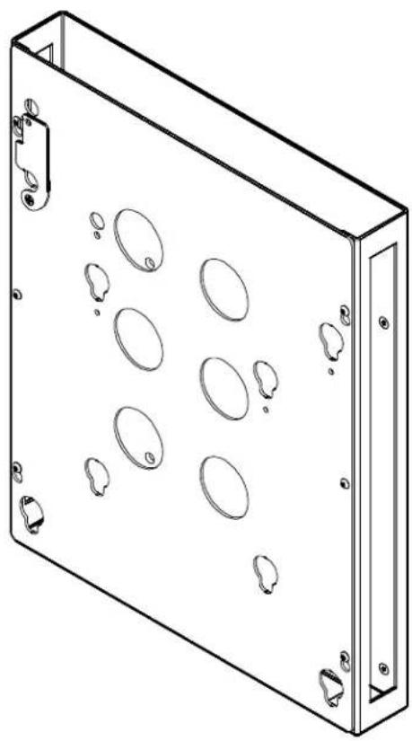
CPU Holder
DISCLAIMER
Milestone AV Technologies and its affiliated corporations and subsidiaries (collectively "Milestone"), intend to make this manual accurate and complete. However, Milestone makes no claim that the information contained herein covers all details, conditions or variations, nor does it provide for every possible contingency in connection with the installation or use of this product. The information contained in this document is subject to change without notice or obligation of any kind. Milestone makes no representation of warranty, expressed or implied, regarding the information contained herein. Milestone assumes no responsibility for accuracy, completeness or sufficiency of the information contained in this document.
Chief® is a registered trademark of Milestone AV Technologies. All rights reserved.

IMPORTANT WARNINGS AND TIONS!

WARNING: A WARNING alerts you to the possibility of serious injury or death if you do not follow the instructions.

CAUTION: A CAUTION alerts you to the possibility of damage or destruction of equipment if you do not follow the corresponding instructions.

WARNING: Failure to read, thoroughly understand, and follow all instructions can result in serious personal injury, damage to equipment, or voiding of factory warranty! It is the installer's responsibility to make sure all components are properly assembled and installed using the instructions provided.

WARNING: Failure to provide adequate structural strength for this component can result in serious personal injury or damage to equipment! It is the installer's responsibility to make sure the structure to which this component is attached can support five times the combined weight of all equipment. Reinforce the structure as required before installing the component. The wall to which the mount is being attached may have a maximum drywall thickness of 5/8" (1.6cm).

WARNING: Exceeding the weight capacity can result in serious personal injury or damage to equipment! It is the installer's responsibility to make sure the combined weight of all components located between the CPU Accessory and the display does not exceed the weight limits for the specific wall mount being used. The CPU Accessory weighs 17 lbs (7.7 kg) which needs to be included in this combined weight total.
DIMENSIONS
![MOUNTING BUTTONS SHOWN IN 14"X14" PATTERN [16.21] 16.00 ID 15.75 [MAX WIDTH OF CPU] 1.81 [MAX DEPTH OF CPU] LOCKING FLAG SHOWN ON 14"X14" PATTERN CPU HOLDER FACEPLATE 12.062 7.000 14.000 7.874 7.874 14.000 (3.28) 20.000 (RECOMMENDED HEIGHT OF CPU) (20.14) MEASUREMENTS: [MILLIMETERS] INCHES](/content/2026/06/1278632/images/a22cd4a08238eb7f4809f7a370ea5bf66613e399ea41b542e4134b614b3f67f1.jpg)
LEGEND
 | Tighten Fastener |
| Apretar elemento de fijación | |
| Befestigungsteil festziehen | |
| Apertar fixador | |
| Serrare il fissaggio | |
| Bevestiging vastdraaien | |
| Serrez les fixations | |
 | Loosen Fastener |
| Aflojar elemento de fijación | |
| Befestigungsteil lösen | |
| Desapertar fixador | |
| Allentare il fissaggio | |
| Bevestiging losdraaien | |
| Desserrez les fixations | |
 | Phillips Screwdriver |
| Destornillador Phillips | |
| Kreuzschlitzschraubendreher | |
| Chave de fendas Phillips | |
| Cacciavite a stella | |
| Kruiskopschroevendraaier | |
| Tournevis à pointe cruciforme | |
 | Open-Ended Wrench |
| Llave de boca | |
| Gabelschlüssel | |
| Chave de bocas | |
| Chiave a punte aperte | |
| Steeksleutel | |
| Clé à fourche | |
 | By Hand |
| A mano | |
| Von Hand | |
| Com a mão | |
| A mano | |
| Met de hand | |
| À la main | |
 | Hex-Head Wrench |
| Llave de cabeza hexagonal | |
| Sechskantschlüssel | |
| Chave de cabeça sextavada | |
| Chiave esagonale | |
| Zeskantsleutel | |
| Clé à tête hexagonale |




Pencil Mark
Marcar con lápiz
Stiftmarkierung
Marcar com lápis
Segno a matita
Potloodmerkteken
Marquage au crayon
Drill Hole
Perforar
Bohrloch
Fazer furo
Praticare un foro
Gat boren
Percez un trou
Adjust
Ajustar
Einstellen
Ajustar
Regolare
Afstellen
Ajuster
Remove
Quitar
Entfernen
Remover
Rimuovere
Verwijderen
Retirez
Optional
Opcional
Optional
Opcional
Opzionale
Optie
En option
Security Wrench
Llave de seguridad
Sicherheitsschlüssel
Chave de segurança
Chiave di sicurezza
Veiligheidssleutel
Clé de sécurité
TOOLS REQUIRED FOR INSTALLATION

PARTS
![A (1) [CPU Holder] B (1) [Faceplate] C (1) [Locking Flag] D (4) [Mounting Button] E (4) [Cable Tie] F (6) [Hook and Loop] G (1) 1/8" H (1) 10-24 x 1/2" J (4) 10-24 x 1/2" K (6) 10-24 x 3/8" L (1) 10-24 M (1) .194x.375x.032](/content/2026/06/1278632/images/a8556b761c0fd90ca0b1d71624edfdefad26544a9a815e7838273fb95b3203d7.jpg)
ASSEMBLY
Assembling CPU Accessory
Attaching Locking Flag
- Attach locking flag (C) to faceplate (B) using one 10-24 x 1/2" Phillips undercut machine screw (H), one spacer (M), and one 10-24 Nylock lock nut (L). (See Figure 1)
NOTE: The locking flag may be installed in one of two locations, dependent upon the display mounting pattern. (See Figure 1)

Figure 1
Attaching Mounting Buttons
- Attach four mounting buttons (D) to CPU holder (A) using four 10-24 x 1/2" flat head cap screws (J). (See Figure 2)
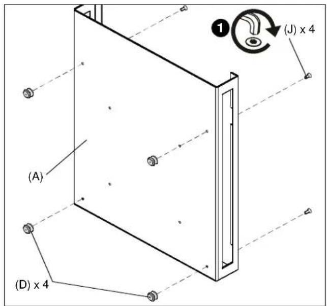
Figure 2
Placing CPU in CPU Holder
- Put hook and loop tabs (F) together so there are 3 squares of hook and loop.
- Remove paper from one side of each of the three hook and loop squares.
- Attach hook and loop squares to the CPU. (See Figure 3)

Figure 3
- Remove paper from hook and loop squares, and press the CPU against the CPU holder (A).
Attaching Faceplate to CPU Box
- Attach faceplate (B) to CPU box (A) using six 10-24 x 3/8" button head cap screws (K). (See Figure 4)

Figure 4
INSTALLATION
Installing CPU Holder with CPU to Mount

WARNING: Exceeding the weight capacity can result in serious personal injury or damage to equipment! It is the installer's responsibility to make sure the combined weight of all components located between the CPU Accessory and the display does not exceed the weight limits for the specific wall mount being used. The CPU Accessory weighs 17 lbs (7.7 kg) which needs to be included in this combined weight total.
Install the CPU holder, with CPU, onto mount and route wires and cables following the instructions provided with the mount. Cable ties (E) are provided for cable management.

WARNING: IMPROPER INSTALLATION CAN LEAD TO CPU HOLDER FALLING! Make certain mounting buttons on CPU holder are fully engaged in teardrop holes in mount and latching flag on mount is fully closed before installing the display.
Installing Display

WARNING: DISPLAY MAY WEIGH IN EXCESS OF 40 LBS. ALWAYS use two people when lifting and follow proper lifting techniques when installing!
IMPORTANT ! : The following procedure assumes that the proper interface bracket for display being mounted has already been installed on display. If no interface bracket is present on display, install bracket to display using instructions included with interface bracket before proceeding.
To install the display:
- Ensure that locking flag is in open position. (See Figure 5)
- While supporting each side of display, align four mounting buttons on display or interface bracket with four teardrop slots in CPU holder (See Figure 5).
- Lower display firmly into place. (See Figure 5)
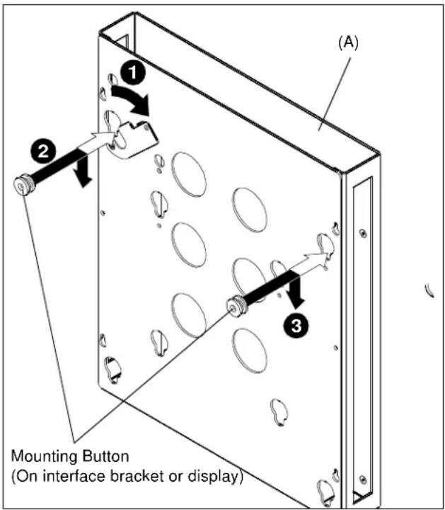
Figure 5
- Ensure mounting buttons are fully seated in teardrop slots.
- Close locking flag.
- Connect cables to display.
Installation Instructions
Marque : Chief
Modèle : PAC253
Catégorie : Support écran plat