
MAC720 - Support écran plat Chief - Notice d'utilisation et mode d'emploi gratuit
Retrouvez gratuitement la notice de l'appareil MAC720 Chief au format PDF.


| Type de produit | Support mural fixe pour écran plat |
| Marque | Chief |
| Modèle | MAC720 |
| Compatibilité des écrans | Écrans plats de 32 à 65 pouces |
| Norme VESA | Jusqu'à 600 x 400 mm |
| Capacité de charge maximale | 56,7 kg (125 lb) |
| Matériau | Acier à haute résistance |
| Dimensions du support | 660 x 445 x 64 mm |
| Poids du support | 5,4 kg |
| Inclinaison | Fixe (non inclinable) |
| Rotation | Non |
| Fixation murale | Montage sur mur en bois ou béton |
| Niveau à bulle intégré | Oui |
| Gestion des câbles | Passage de câbles intégré |
| Outils nécessaires | Perceuse, niveau, clé Allen fournie |
| Garantie | 10 ans |
| Entretien | Nettoyer avec un chiffon doux et sec |
| Sécurité | Vis de sécurité inclues pour éviter le vol |
| Pièces détachées | Disponibles sur le site Chief |
| Réparabilité | Support de réparation en ligne |
FOIRE AUX QUESTIONS - MAC720 Chief
Questions des utilisateurs sur MAC720 Chief
0 question sur cet appareil. Repondez a celles que vous connaissez ou posez la votre.
Poser une nouvelle question sur cet appareil
Téléchargez la notice de votre Support écran plat au format PDF gratuitement ! Retrouvez votre notice MAC720 - Chief et reprennez votre appareil électronique en main. Sur cette page sont publiés tous les documents nécessaires à l'utilisation de votre appareil MAC720 de la marque Chief.
MODE D'EMPLOI MAC720 Chief
INSTALLATION INSTRUCTIONS

Cart and Stand Clamp Head Accessory
DISCLAIMER
CSAV, Inc., and its affiliated corporations and subsidiaries (collectively, "CSAV"), intend to make this manual accurate and complete. However, CSAV makes no claim that the information contained herein covers all details, conditions or variations, nor does it provide for every possible contingency in connection with the installation or use of this product. The information contained in this document is subject to change without notice or obligation of any kind. CSAV makes no representation of warranty, expressed or implied, regarding the information contained herein. CSAV assumes no responsibility for accuracy, completeness or sufficiency of the information contained in this document.

IMPORTANT WARNINGS AND
CAUTIONS!

WARNING: A WARNING alerts you to the possibility of serious injury or death if you do not follow the instructions.

CAUTION: A CAUTION alerts you to the possibility of damage or destruction of equipment if you do not follow the corresponding instructions.

WARNING: Failure to read, thoroughly understand, and follow all instructions can result in serious personal injury, damage to equipment, or voiding of factory warranty! It is the installer's responsibility to make sure all components are properly assembled and installed using the instructions provided.

WARNING: Exceeding the weight capacity can result in serious personal injury or damage to equipment! It is the installer's responsibility to make sure the combined weight of all components on the cart/stand does not exceed 125 lbs (56.70 kg) for the MFC, 125 lbs (56.70 kg) for the MF1, and 250 lbs (113.40 kg) for the MF2 (125 lbs (56.70 kg) per faceplate).
LEGEND


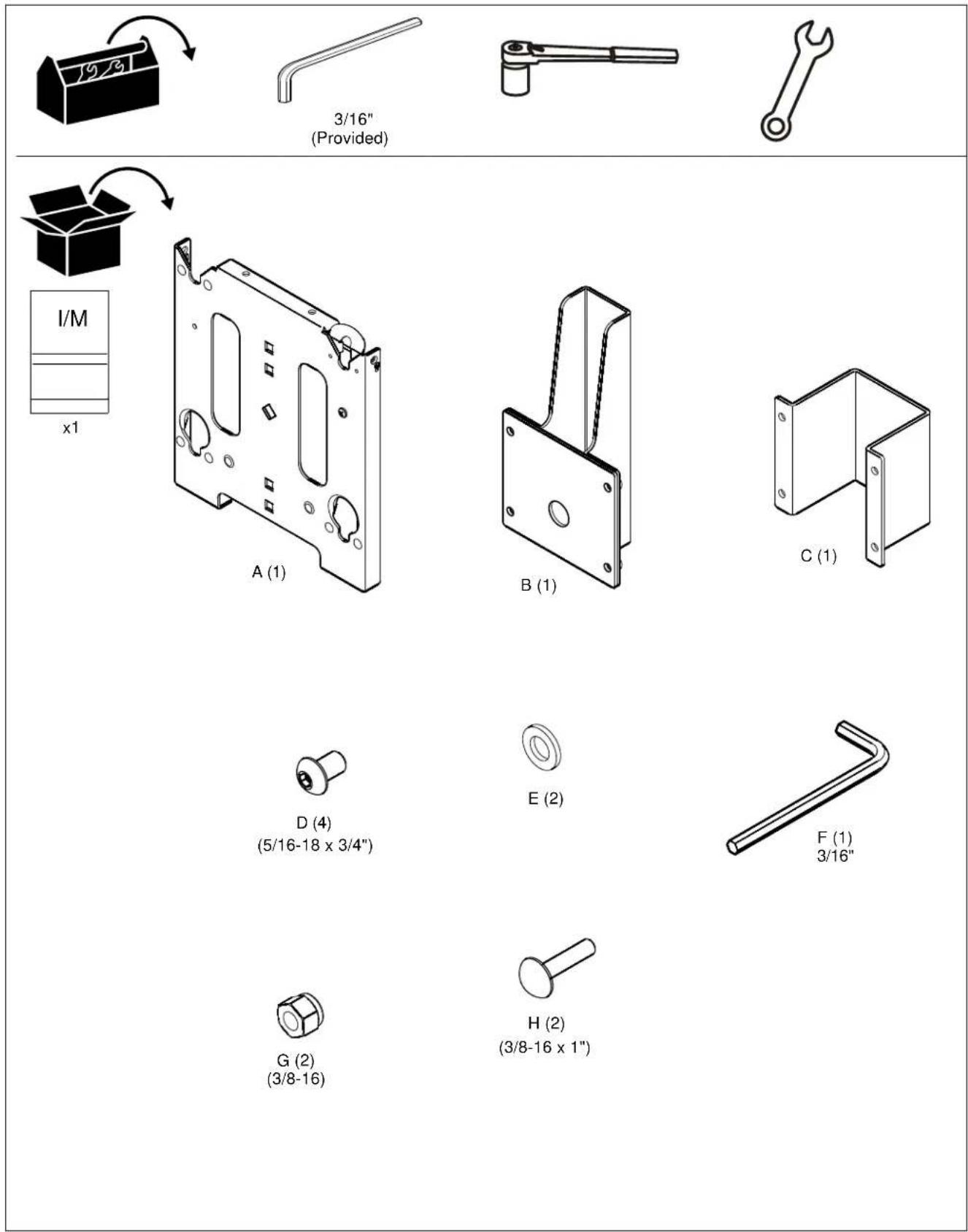
TOOLS REQUIRED FOR INSTALLATION AND PARTS
ASSEMBLY AND INSTALLATION

WARNING: EXCEEDING MAXIMUM WEIGHT CAPACITY MAY LEAD TO SERIOUS PERSONAL INJURY OR DAMAGE TO EQUIPMENT! It is the installer's responsibility to ensure the total amount of weight placed on the cart/stand does not exceed 125 lbs (56.70 kg) for the MFC, 125 lbs (56.70 kg) for the MF1, and 250 lbs (113.40 kg) for the MF2 [125 lbs (56.70 kg) per faceplate].
Installing Display(s) to Cart/Stand
- Install display(s) to cart or stand following the installation instructions included with the cart/stand.
Assembly for Single Display
- Attach faceplate (A) to bracket (B) using two 3/8-16 x 1" roundhead carriage bolts (H), two spacers (E), and two 3/8-16 Nylock lock nuts (G). (See Figure 1)

Figure 1
- Secure faceplate with bracket to clamp bracket (C) using four 5/16-18 x 3/4" buttonhead cap screws (D). (See Figure 2)
NOTE: The faceplate assembly must be attached to the clamp bracket below the knob on the lower part of the cart/stand post.

Figure 2
Assembly for Dual Display

WARNING: TIPPING HAZARD! Place MAC720 only on FRONT of MFC and MF1. MAC720 may be placed on both FRONT and BACK of MF2.
-
Attach first faceplate (A) to bracket (B) using two 3/8-16 x 1" roundhead carriage bolts (H), two spacers (E), and two 3/8-16 Nylock lock nuts (G). (See Figure 1)
-
Attach second faceplate (A) to bracket (B) using two 3/8-16 x 1" roundhead carriage bolts (H), two spacers (E) and two 3/8-16 and two 3/8-16 Nylock lock nuts (G). (See Figure 3)
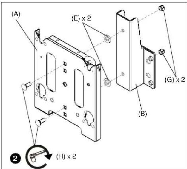
Figure 3
- Secure faceplate assemblies with bracket to clamp brackets (C) onto cart/stand post using four 5/16-18 x 3/4" buttonhead cap screws (D) on EACH assembly. (See Figure 4)
NOTE: The faceplate assembly must be attached to the clamp bracket below the knob on the lower part of the cart/stand post.

Figure 4
Attaching Display(s)
- While supporting both sides of display, align four mounting buttons on display or interface bracket with four mounting holes in faceplate. (See Figures 5 and 6)
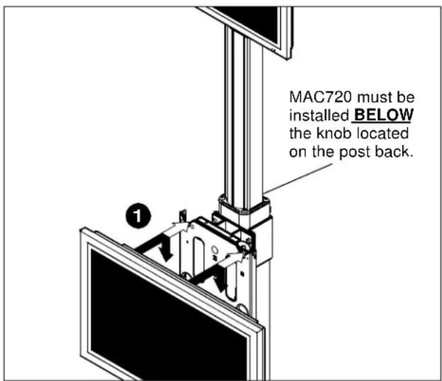
Figure 5

WARNING: EACH DISPLAY MAY WEIGH IN EXCESS OF 40 LBS! Always use two people and proper lifting techniques when installing or positioning display on stand.
- Lower display into place listening for audible "click" to ensure recessed area of mounting buttons are properly seated in lower area of mounting holes. (See Figures 5 and 6)

WARNING: IMPROPER INSTALLATION CAN LEAD TO CART/STAND OR DISPLAY FALLING CAUSING SERIOUS PERSONAL INJURY OR DAMAGE TO EQUIPMENT! Ensure mounting buttons are completely engaged in mounting holes.
NOTE: Holes are provided in the faceplate for use with a padlock or similar locking device, if desired. In addition, the pin and nut may be removed from the upper holes and moved to the lower holes for use as a more permanent locking device. (See Figure 6)
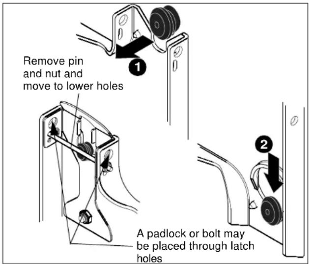
Figure 6
- To adjust location of display on cart/stand, support display(s) and carefully loosen four 5/16-18 x 3/4" buttonhead cap screws (D) on each faceplate assembly.
- Slide display(s) up on post to desired position and tighten four 5/16-18 x 3/4" buttonhead cap screws (D) for each faceplate assembly. (See Figure 2 and 4)
- Refer to the installation instructions provided with the cart/stand for further information on Tilting Display, Removing Display, Cable Management and Cart/Stand Maintenance.
Marque : Chief
Modèle : MAC720
Catégorie : Support écran plat