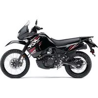
KLR650 - Moto KAWASAKI - Notice d'utilisation et mode d'emploi gratuit
Retrouvez gratuitement la notice de l'appareil KLR650 KAWASAKI au format PDF.


| Type de produit | Moto tout-terrain / dual-sport |
| Marque | Kawasaki |
| Modèle | KLR650 |
| Dimensions (L x l x H) | 2250 x 980 x 1350 mm |
| Poids à sec | 196 kg |
| Capacité du réservoir | 15,5 L |
| Type de moteur | Monocylindre 4 temps |
| Cylindrée | 651 cm³ |
| Puissance max | 43 ch à 6000 tr/min |
| Alimentation | Essence sans plomb |
| Refroidissement | Liquide |
| Transmission | 5 vitesses, chaîne |
| Frein avant | Disque simple Ø 300 mm |
| Frein arrière | Disque simple Ø 240 mm |
| Suspension avant | Télescopique, déb. 200 mm |
| Suspension arrière | Uni-Trak, déb. 185 mm |
| Hauteur de selle | 890 mm |
| Fonctions principales | Démarrage électrique, allumage électronique, éclairage halogène |
| Entretien courant | Vidange huile tous 6000 km, filtre à air nettoyé tous 12000 km |
| Nettoyage | Eau savonneuse, éviter haute pression sur éléments électriques |
| Sécurité | Freins à disque, béquille latérale avec coupe-circuit |
| Pièces détachées | Disponibles chez concessionnaire Kawasaki |
| Réparabilité | Indice de réparabilité : 7,5/10 (estimation) |
| Informations générales | Manuel d'utilisation et d'entretien fourni (143 pages) |
FOIRE AUX QUESTIONS - KLR650 KAWASAKI
Questions des utilisateurs sur KLR650 KAWASAKI
0 question sur cet appareil. Repondez a celles que vous connaissez ou posez la votre.
Poser une nouvelle question sur cet appareil
Téléchargez la notice de votre Moto au format PDF gratuitement ! Retrouvez votre notice KLR650 - KAWASAKI et reprennez votre appareil électronique en main. Sur cette page sont publiés tous les documents nécessaires à l'utilisation de votre appareil KLR650 de la marque KAWASAKI.
MODE D'EMPLOI KLR650 KAWASAKI
Kawasaki
Includes:
- Important Safety Information
- Operating Instructions
- Maintenance and Storage
KLR650
Motorcycle
OWNER'S MANUAL
Quick Reference Guide
This Quick Reference Guide will assist you in finding the information you're looking for.
General Information
How to Ride the Motorcycle
Safe Operation
Maintenance and Adjustment
Storage
A Table of Contents is included after the Foreword.
Troubleshooting Guide
Whenever you see the symbols shown below, heed their instructions! Always follow safe operating and maintenance practices.
WARNING
This warning symbol identifies special instructions or procedures which, if not correctly followed, could result in personal injury, or loss of life.
CAUTION
This caution symbol identifies special instructions or procedures which, if not strictly observed, could result in damage to or destruction of equipment.
NOTE
○This note symbol indicates points of particular interest for more efficient and convenient operation.
NOTICE
THIS PRODUCT HAS BEEN MANUFACTURED FOR USE IN A REASONABLE AND PRUDENT MANNER BY A QUALIFIED OPERATOR AND AS A VEHICLE ONLY.
FOREWORD
Congratulations on your purchase of a new Kawasaki Motorcycle. Your new motorcycle is the product of Kawasaki's advanced engineering, exhaustive testing, and continuous striving for superior reliability, safety and performance.
Please read this Owner's Manual carefully before riding so that you will be thoroughly familiar with the proper operation of your motorcycle's controls, its features, capabilities, and limitations. This manual offers many safe riding tips, but its purpose is not to provide instruction in all the techniques and skills required to ride a motorcycle safely. Kawasaki strongly recommends that all operators of this vehicle enroll in a motorcycle rider training program to attain awareness of the mental and physical requirements necessary for safe motorcycle operation.
To ensure a long, trouble-free life for your motorcycle, give it the proper care and maintenance described in this manual. For those who would like more detailed information on their Kawasaki Motorcycle, a Service Manual is available for purchase from any authorized Kawasaki motorcycle dealer. The Service Manual contains detailed disassembly and maintenance information. Those who plan to do their own work should, of course, be competent mechanics and possess the special tools described in the Service Manual.
Keep this Owner's Manual aboard your motorcycle at all times so that you can refer to it whenever you need information.
This manual should be considered a permanent part of the motorcycle and should remain with the motorcycle when it is sold.
All rights reserved. No part of this publication may be reproduced without our prior written permission.
This publication includes the latest information available at the time of printing. However, there may be minor differences between the actual product and illustrations and text in this manual.
All products are subject to change without prior notice or obligation.
KAWASAKI HEAVY INDUSTRIES, LTD.
Consumer Products & Machinery Company
© 2006 Kawasaki Heavy Industries, Ltd.
April. 2006. (1).
TABLE OF CONTENTS
Specifications 8
Serial Number Locations....11
Location of Parts 12
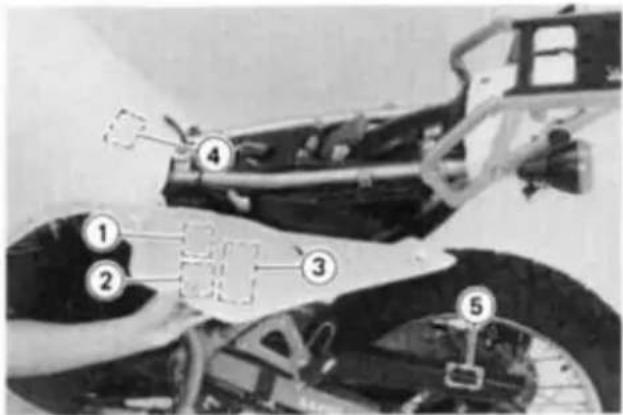
Location of Labels 15
Loading Information 17
General Information 20
Meter Instruments....20
Speedometer and Tachometer.....21
Coolant Temperature Gauge....21
Indicator Lights 21
Key 22
Ignition Switch/Steering Lock 23
Right Handlebar Switches 24
Engine Stop Switch 24
Starter Button 25
Left Handlebar Switches 25
Dimmer Switch 25
Turn Signal Switch 26
Horn Button 26
Fuel Tank Cap 26
Fuel Tank 27
Fuel Tap....31
Side Stand 32
Helmet Hook 33
Tool Kit Container 34
Tool Kit....34
Rear Carrier 35
Break-In 36
How to Ride the Motorcycle....38
Starting the Engine....38
Jump Starting 41
Moving Off 43
Shifting Gears 44
Braking 45
Stopping the Engine 46
Stopping the Motorcycle in an Emergency 47
Parking 48
Safe Operation 49
Safe Riding Technique....49
Daily Safety Checks....51
Additional Considerations for Off Road Operation....53
Maintenance and Adjustment....54
Periodic Maintenance Chart 59
Engine Oil 62
Cooling System....66
Spark Plug 70
Valve Clearance 71
Balancer Chain....72
Evaporative Emission Control System 73
Air Cleaner 74
Throttle Grip....77
Choke Lever 80
Carburetor 81
Clutch 83
Spark Arrester 85
Drive Chain 86
Brakes 92
Brake Light Switches 95
Front Fork 96
Rear Shock Absorber....98
Wheels....101
Battery 103
Headlight Beam 109
Fuses 110
Fuel System 111
General Lubrication....113
Cleaning 115
Bolt and Nut Tightening....119
Storage 121
Troubleshooting Guide 124
Reporting Safety Defects 125
Owner Satisfaction 126
Environmental Protection 128
Maintenance Record 129
Label Information 133
SPECIFICATIONS
DIMENSIONS
| Overall Length | 2,205 mm (86.81 in) |
| Overall Width | 940 mm (37.01 in) |
| Overall Height | 1,345 mm (52.95 in) |
| Wheelbase | 1,495 mm (58.86 in) |
| Road Clearance | 240 mm (9.45 in) |
| Dry Weight | 153 kg (337 lb) <cal> 135.5 kg (338 lb) |
ENGINE
| Type | DOHC, single-cylinder, 4-stroke, liquid-cooled | |
| Displacement | 651 cm^3 (39.7 cu in.) | |
| Bore x Stroke | 100.0 x 83.0 mm (3.94 x 3.27 in) | |
| Compression Ratio | 9.5 : 1 | |
| Starting System | Electric starter | |
| Carburetor | Keihin CVK40 | |
| Ignition System | C.D.I. | |
| Ignition Timing | 10° BTDC @1,300 r/min (rpm) ~30° BTDC @3,300 r/min (rpm) | |
| Spark plug | NGK DPR8EA-9 or ND X24EPR-U9 | |
| Lubrication System | Forced lubrication (wet sump) | |
| Engine Oil | Type: | API SE, SF or SG |
| : | API SH, SJ or SL with JASO MA | |
| SAE 10W-40 |
Capacity: 2,5 L (2.6 US qt)
Coolant Capacity 1,3 L (1.4 US qt)
TRANSMISSION
| Transmission Type | 5-speed, constant mesh, return shift | |
| Clutch Type | Wet, multi disc | |
| Driving System | Chain drive | |
| Primary Reduction Ratio | 2.272 (75/33) | |
| Final Reduction Ratio | 2.866 (43/15) | |
| Overall Drive Ratio | 5.157(Top gear) | |
| Gear Ratio: | 1st | 2.266 (34/15) |
| 2nd | 1.444 (26/18) | |
| 3rd | 1.136 (25/22) | |
| 4th | 0.954 (21/22) | |
| 5th | 0.791 (19/24) | |
FRAME
| Castor | 28" | |
| Trail | 112 mm (4.41 in) | |
| Tire Size: | Front | 90/90-21 54S |
| Rear | 130/80-17 65S | |
| Rim Size: | Front | 1.6 x 21 |
| Rear | 2.50 x 17 | |
| Fuel Tank Capacity | 23L (6.1 US gal) | |
ELECTRICAL EQUIPMENT
| Battery | 12 V 14 Ah |
| Headlight | 12 V 60/55 W |
| Tail/Brake Light | 12 V 5/21 W |
Specifications subject to change without notice.
SERIAL NUMBER LOCATIONS
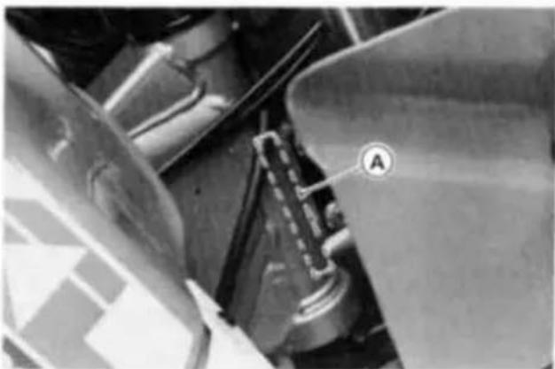
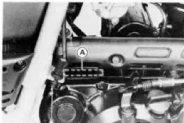
The engine and frame serial numbers are used to register the motorcycle. They are the only means of identifying your particular machine from others of the same model type. These serial numbers may be needed by your dealer when ordering parts. In the event of theft, the investigating authorities will require both numbers as well as the model type and any peculiar features of your machine that can help them identify it.
Frame No.
natural_image
Close-up of mechanical components with a labeled section (A) and no visible text or symbolsA. Frame Number
Engine No.
natural_image
Close-up of a mechanical engine component with no visible text or symbolsA. Engine Number
LOCATION OF PARTS

- Clutch Lever
- Dimmer Switch
- Starter Lockout Switch
- Meter Instruments
- Brake Fluid Reservoir (Front)
- Engine Stop Switch
- Front Brake Lever
- Horn Button
- Turn Signal Switch
- Choke Lever
- Ignition Switch/Steering Lock
- Starter Button
-
Throttle Grip
-
Front Fork
- Headlight
- Turn Signal Light
- Fuel Tank
- Fuel Tap
- Side Stand Switch
- Battery
- Tool Kit Container
- Brake Disc
- Brake Caliper
- Radiator
- Shift Pedal
- Side Stand
- Drive Chain
- Helmet Hook


- License Plate Light
- Tail/Brake Light
- Muffler
- Rear Carrier
- Seat
- Air Cleaner Element
- Brake Fluid Reservoir (Rear)
- Carburetor
- Fuel Tank Cap
- Coolant Reserve Tank
- Horn
- Rear Brake Light Switch
- Rear Brake Pedal
- Oil Level Gauge
- Idle Adjusting Screw
》《《《《《《《《《《《《《《《《《《《《《《《《《《《《 》《《《《《 LOCATION OF LABELS «《《《《《《
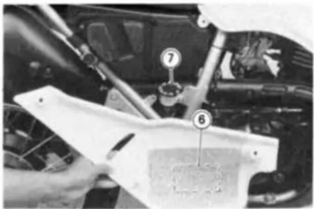

natural_image
Close-up of a mechanical component with coiled spring and threaded shaft (no visible text or symbols)- Battery Vent Hose
- Vehicle Emission Control Information
*3. Vacuum Hose Routing Diagram - Tire and Load Data
- Important Drive Chain Information
- Engine Oil and Oil Filter
- Brake Fluid (Rear)
- Noise Emission Control Information
* : only on California model
(For further information of label, refer to the "LABEL INFORMATION" chapter.)


natural_image
Exterior view of a battery with a label showing '15' and a dashed paper tag (no readable text or symbols beyond the label)
natural_image
Close-up of a mechanical or electronic component with no visible text or symbols- Radiator Cap
- Brake Fluid (Front)
- Brake-In Caution
- Important Break-In Instruction
- Fuel Level
- Rear Carrier
- Battery Poison/Danger
*: only on California model
(For further information of label, refer to the "LABEL INFORMATION" chapter.)
LOADING INFORMATION
WARNING
Incorrect loading, improper installation or use of accessories, or modification of your motorcycle may result in an unsafe riding condition. Before you ride the motorcycle, make sure that the motorcycle is not overloaded and that you have followed these instructions.
With the exception of genuine Kawasaki Parts and Accessories, Kawasaki has no control over the design or application of accessories. In some cases, improper installation or use of accessories, or motorcycle modification, will void the motorcycle warranty. In selecting and using accessories, and in loading the motorcycle, you are personally responsible for your own safety and the safety of other persons involved.
NOTE
○Kawasaki Parts and Accessories have been specially designed for use on Kawasaki motorcycles. We strongly recommend that all parts and accessories you add to your motorcycle be genuine Kawasaki components.
Because a motorcycle is sensitive to changes in weight and aerodynamic forces, you must take extreme care in carrying cargo, passengers and/or in the fitting of additional accessories. The following general guidelines have been prepared to assist you in making your determinations.
-
Any passenger should be thoroughly familiar with motorcycle operation. The passenger can affect control of the motorcycle by improper positioning during cornering and sudden movements. It is important that the passenger sit still while the motorcycle is in motion and not interfere with the operation of the motorcycle. Do not carry animals on your motorcycle.
-
You should instruct any passenger before riding to keep his feet on the passenger footpegs and hold on to the operator, seat strap or grab rail. Do not carry a passenger unless he or she is tall enough to reach the footpegs and footpegs are provided.
-
All baggage should be carried as low as possible to reduce the effect on the motorcycle center of gravity. Baggage weight should also be distributed equally on both sides of the motorcycle. Avoid carrying baggage
that extends beyond the rear of the motorcycle.
-
Baggage should be securely attached. Make sure that the baggage will not move around while you are riding. Recheck baggage security as often as possible (not while the motorcycle is in motion) and adjust as necessary.
-
Do not carry heavy or bulky items on a luggage rack. They are designed for light items, and overloading can affect handling due to changes in weight distribution and aerodynamic forces.
-
Do not install accessories or carry baggage that impairs the performance of the motorcycle. Make sure that you have not adversely affected any lighting components, road clearance, banking capability (i.e., lean angle), control operation, wheel travel, front fork movement, or any
other aspect of the motorcycle's operation.
-
Weight attached to the handlebar or front fork will increase the mass of the steering assembly and can result in an unsafe riding condition.
-
Fairings, windshields, backrests, and other large items have the capability of adversely affecting stability and handling of the motorcycle, not only because of their weight, but also due to the aerodynamic forces acting on these surfaces while the motorcycle is in operation. Poorly designed or installed items can result in an unsafe riding condition.
-
This motorcycle was not intended to be equipped with a sidecar or to be used to tow any trailer or other vehicle. Kawasaki does not manufacture sidecars or trailers for motorcycles and cannot predict the effects of such accessories on handling or stability, but can only warn that the effects can be adverse and that Kawasaki cannot assume responsibility for the results of such unintended use of the motorcycle. Furthermore, any adverse effects on motorcycle components caused by the use of such accessories will not be remedied under warranty.
Maximum Load
Weight of rider, passenger, baggage, and accessories must not exceed 182 kg (401 lb).
GENERAL INFORMATION
Meter Instruments

A. Tachometer
B. Red Zone
C. Coolant Temperature Gauge
D. Speedometer
E. Trip Meter
F. Odometer
G. Trip Reset Knob
H. Neutral Indicator Light
I. Turn Signal Indicator Light
J. High Beam Indicator Light
Speedometer and Tachometer
The speedometer shows the speed of the vehicle. In the speedometer face are the odometer and trip meter. The odometer shows the total distance that the vehicle has been ridden. The trip meter shows the distance traveled since it was last reset to zero. The trip meter can be reset to zero by turning the reset knob clockwise.
The tachometer shows the engine speed in the revolutions per minute (r/min, rpm). On the right side of the tachometer face is a portion called the "red zone." Engine r/min (rpm) in the red zone is above maximum recommended engine speed and is also above the range for good performance.
| CAUTION |
| Engine r/min (rpm) should not be allowed to enter the red zone; operation in the red zone will overstress the engine and may cause serious engine damage. |
Coolant Temperature Gauge
This gauge shows the temperature of coolant. Ordinarily, the needle should stay within the fine line. If the needle reaches the thick line, stop the engine and check the coolant level in the reserve tank after the engine cools down.
CAUTION
Do not let the engine continue running when the gauge needle reaches the thick line. Prolonged engine operation will result in severe damage from overheating.
Indicator Lights
NEUTRAL: When the transmission is in neutral, the neutral indicator light is lit.
TURN: When the turn signal switch is turned to left or right, the turn signal indicator light flashes on and off.
HIGH BEAM: When the headlight is on high beam, the high beam indicator light is lit.
Key
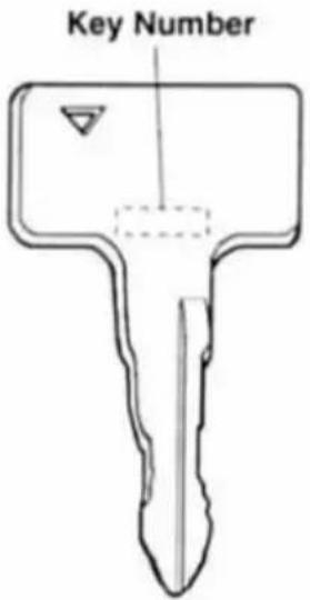
This motorcycle has a combination key, which is used for the ignition switch/steering lock, fuel tank cap, and helmet hook.
Blank keys are available at your Kawasaki dealers. Ask your dealer to make any additional spare keys you may need, using your original key as a master, or using the key code on the tag with your keys.
Record the code from the tag with your keys here. Participating Kawasaki dealers can use the code to make a new key in the event that your original keys are lost.
Write your key number here.
Ignition Switch/Steering Lock
This is a four-position, key-operated switch. The key can be removed from the switch when it is in the OFF, LOCK, or P(Park) position.

A. Ignition Switch/Steering Lock
B. ON position
C. OFF position
D. LOCK position
E. P (Park) position
| ON | Engine on. All electrical equipment can be used. |
| OFF | Engine off. All electrical circuits off. |
| LOCK | Steering locked. Engine off. All electrical circuits off. |
| P(Park) | Steering locked. Engine off. Taillight and license plate light on. All other electrical circuits cut off. |
NOTE
The tail and license plate lights are on whenever the ignition key is in the ON position. The headlight goes on when the starter button is released after starting the engine. To avoid battery discharge, always start the engine immediately after turning the ignition key to "ON".
○If you leave the P(Park) position on for a long time (one hour), the battery may become totally discharged.
To lock the steering:
- Turn the handlebar fully to the left.
- With the ignition key in the OFF position, push down and release the key.
- Turn the key to LOCK or P(Park) position.
- Pull the key out.
Right Handlebar Switches Engine Stop Switch
In addition to the ignition switch, the engine stop switch must be in the ○ (RUN) position for the motorcycle to operate.
The engine stop switch is for emergency use. If some emergency requires stopping the engine, move the engine stop switch to the ☒ (OFF) position.
NOTE
Although the engine stop switch stops the engine, it does not turn off all the electrical circuits. Ordinarily, the ignition switch should be used to stop the engine.

A. Engine Stop Switch
B. Starter Button
Starter Button
The starter button operates the electric starter when pushed with the clutch lever pulled in or the transmission in neutral.
Refer to the Starting the Engine section of the "How to Ride the Motorcycle" chapter for starting instructions.
Left Handlebar Switches Dimmer Switch
High or low beam can be selected with the dimmer switch. When the headlight is on high beam, the high beam indicator light is lit.
High beam ..... (HI or ID)
Low beam ..... (LO or ID)
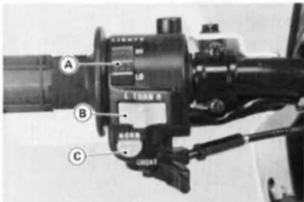
A. Dimmer Switch
B. Turn Signal Switch
C. Horn Button
Turn Signal Switch
When the turn signal switch is turned to the left or right, the corresponding turn signals flash on and off.
To stop flashing, push the switch in.
Left ..... (L or ♦ )
Right ..... (R or ⇔)
Horn Button
When the horn button is pushed, the horn sounds.
Fuel Tank Cap
To open the fuel tank cap, insert the ignition key into the fuel tank cap and turn the key to the right.
To close the cap, push it down into place with the key inserted. The key can be removed by turning it to the left to the original position.

A. Ignition Key
B. Fuel Tank Cap
NOTE
- The fuel tank cap cannot be closed without the key inserted, and the key cannot be removed unless the cap is locked properly.
- Do not push on the key to close the cap, or the cap cannot be locked.
Fuel Tank
The following octane rating gasoline is recommended in the fuel tank. Avoid filling the tank in the rain or where heavy dust is blowing so that the fuel does not get contaminated.
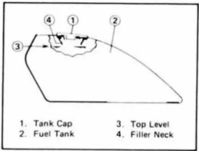
▲WARNING
Gasoline is extremely flammable and can be explosive under certain conditions. Turn the ignition key to "OFF". Do not smoke. Make sure the area is well ventilated and free from any source of flame or sparks; this includes any appliance with a pilot light. Never fill the tank so the fuel level rises into the filler neck. If the tank is overfilled, heat may cause the fuel to expand and overflow through the vents in the tank cap.
After refueling, make sure the fuel tank cap is closed securely. If gasoline is spilled on the fuel tank, wipe it off immediately.
CAUTION
California models only: Never fill the tank so the fuel level rises into the filler neck. If the tank is overfilled, heat may cause the fuel to expand and flow into the Evaporative Emission Control System resulting in hard starting and engine hesitation.
Fuel Requirements:
Fuel Type
Use clean, fresh unleaded gasoline with a minimum Antiknock Index of 87. The Antiknock Index is posted on service station pumps in the U.S.A. The octane rating of a gasoline is a measure of its resistance to detonation or "knocking." The Antiknock Index is an average of the Research Octane Number (RON) and the Motor Octane Number (MON) as shown in the table.
| Octane Rating Method | Minimum Rating |
| Antiknock Index (RON + MON)2 | 87 |
| Research Octane Number (RON) | 91 |
| CAUTION |
| If engine "knocking" or "pinging" occurs, use a different brand of gasoline of a higher octane rating. If this condition is allowed to continue it can lead to severe engine damage.Gasoline quality is important. Fuels of low quality or not meeting standard industry specifications may result in unsatisfactory performance. Operating problems that result from the use of poor quality or nonrecommended fuel may not be covered under your warranty. |
Fuels Containing Oxygenates
Gasoline frequently contains oxygenates (alcohols and ethers) especially in areas of the U.S. and Canada which are required to sell such reformulated fuels as part of a strategy to reduce exhaust emissions.
The types and volume of fuel oxygenates approved for use in unleaded gasoline by the U.S. Environmental Protection Agency include a broad range of alcohols and ethers, but only two components have seen any significant level of commercial use.
Gasoline/Alcohol Blends - Gasoline containing up to 10% ethanol (alcohol produced from agricultural products such as corn), also known as "gasohol" is approved for use.
| CAUTION |
| Avoid using blends of unleaded gasoline and methanol (wood alcohol) whenever possible, and never use "gasohol" containing more than 5% methanol. Fuel system damage and performance problems may result. |
Gasoline/Ether Blends - The most common ether is methyl tertiary butyl ether (MTBE). You may use gasoline containing up to 15% MTBE.
NOTE
○ Other oxygenates approved for use in unleaded gasoline include TAME (up to 16.7%) and ETBE (up to 17.2%). Fuel containing these oxygenates can also be used in your Kawasaki.
| CAUTION |
| Never use gasoline with an octane rating lower than the minimum specified by Kawasaki.Never use "gasohol" with more than 10% ethanol, or more than 5% methanol. Gasoline containing methanol must also be blended with cosolvents and corrosion inhibitors.Certain ingredients of gasoline may cause paint fading or damage. Be extra careful not to spill gasoline or gasoline oxygenate blends during refueling.When not operating your Kawasaki for 30 to 60 days, mix a fuel stabilizer (such as STA-BIL) with the gasoline in the fuel tank. Fuel stabilizer additives inhibit oxidation of the fuel which minimizes gummy deposits.Never store this product with "gasohol" in the fuel system. Before storage it is recommended that you drain all fuel from the fuel tank and carburetors. See the Storage section in this manual. |
Fuel Tap
The fuel tap has three positions: OFF, ON, and RES (Reserve). For normal operation turn the tap lever to the ON position. If the fuel runs out with the tap in the ON position, the last 2.9 L (0.77 US gal) of fuel can be used by turning the fuel tap lever to the RES.

A. Fuel Tap
B. ON position
C. OFF position
D. RES position
With the fuel tap in the ON or RES position fuel flows to carburetor only when the engine is started or is running, and fuel supply is shut off when the engine is stopped.
Turn the fuel tap lever to the OFF position when the fuel tank is removed for maintenance and adjustments or the motorcycle is stored for long time.
NOTE
○Since riding distance is limited when on RES, refuel at the earliest opportunity.
○ Make certain that the fuel tap lever is turned to ON (Not RES) after filling up the fuel tank.
WARNING
Practice operating the fuel tap with the motorcycle stopped. To prevent an accident you should be able to operate the fuel tap while riding without taking your eyes off the road.
Be careful not to touch the hot engine while operating the fuel tap.
Side Stand
The motorcycle is equipped with a side stand.

natural_image
Close-up of a mechanical device with labeled component 'A' (no readable text or symbols beyond label)A. Side Stand
NOTE
○ When using the side stand, turn the handlebar to the left.
Whenever the side stand is used, make it a practice to kick the stand fully up before sitting on the motorcycle.
NOTE
The motorcycle is equipped with a side stand switch. This switch is designed so that the engine stops if the clutch is engaged with the transmission in gear when the side stand is left down.
Helmet Hook
Helmet can be secured to the motor-cycle using the helmet hook located under the rear carrier.
The helmet hook can be unlocked by inserting the ignition key into the lock, and turning the key to the right.
▲WARNING
Do not ride the motorcycle with a helmet attached to the hook. The helmet could cause an accident by distracting the operator or interfering with normal vehicle operation.

A. Helmet Hook
B. Tool Kit Container
C. Tool Kit
D. Rear Carrier
Tool Kit Container
The tool kit container is located on the rear carrier. Use this container to keep the tool kit that should be kept with the motorcycle.
Tool Kit
The minor adjustments and replacement of parts explained in this manual can be performed with the tools in the kit.
Rear Carrier
The motorcycle is equipped with a carrier on the rear.
| Vehicle Total Payload(must not exceed.) | 182 kg(401 lb) |
| Rear CarrierMaximum Load Capacity | 10 kg(22 lb) |
▲WARNING
Never exceed the rear carrier load limit of 10 kg (22 lb). It is designed for light items, and overloading can affect handling due to changes in weight distribution and aerodynamic forces.
Do not exceed the vehicle speed of 130 km/h (80 mph) when carrying a load of more than 5 kg (11 lb) on the carrier.
Overloading and failure to adjust speed to compensate for addition of cargo may result in loss of control and an accident. Speed must also be adjusted to suit various road and weather conditions.
》》》》》》》》》》》》》》》》》》》》》》》》》》》》》》》》》》》》》》》》》》》》》》》》》》》》》》》》》》》》》》》》》》》》》》》》》》》》》》》》》》》》》》》》》》》》》》》》》》》》》,BREAK-IN 《《《《《《《《《《《《《《《《《《《《《《《《《《《《《《《《《《《《《《
The first 1,600 km (1,000 mi) that the motorcycle is ridden is designated as the break-in period. If the motorcycle is not used carefully during this period, you may very well end up with a "broken down" instead of a "broken in" motorcycle after a few thousand kilometers.
The following rules should be observed during the break-in period.
●The table shows maximum recommended engine speed during the break-in period.
| Distance traveled | Maximum engine speed |
| 0 ~ 800 km (0 ~ 500 mi) | 4,000 r/min (rpm) |
| 800 ~ 1,600 km (500 ~ 1,000 mi) | 6,000 r/min (rpm) |
- Do not start moving or race the engine immediately after starting it, even if the engine is already warm. Run the engine for two or three minutes at idle speed to give the oil a chance to work up into all the engine parts.
● Do not race the engine while the transmission is in neutral.
In addition to the above, at 800 km (500 mi) it is extremely important that the owner have the initial maintenance service performed by a competent mechanic following the procedures in the Service Manual.
WARNING
New tires are slippery and may cause loss of control and injury.
A break-in period of 160 km (100 miles) is necessary to establish normal tire traction.
During break-in, avoid sudden and maximum braking and acceleration, and hard cornering.
》《》《》《》《》《》《》《》《》《》《》《》《》《》《》《》《》《》《》《》《》《》《》《》《》《》《》《》《》《》《》《》《》《》《》《》《》《》《》《》《》《》《》《》《》《》《》《》《》《》《》
Starting the Engine
●Turn the fuel tap lever to the ON position.
- Check that the engine stop switch is in the RUN position.
●Turn the ignition key to "ON".
● Make certain the transmission is in neutral or the clutch is disengaged.

A. Engine Stop Switch
B. Starter Button
C. Neutral Indicator Light
D. Ignition Switch
E. ON position
- If the engine is cold, push the choke lever all the way to the left.
NOTE
When the engine is already warm or on hot days (35°C, 95°F or more), open the throttle part way instead of using the choke, and then start the engine.
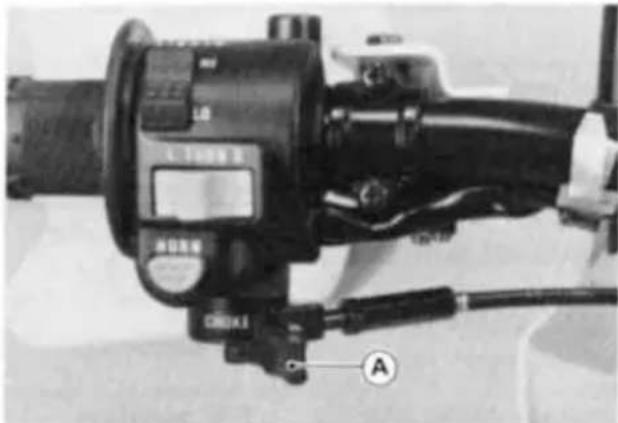
natural_image
Close-up of a black HORN motor with attached cable and adjustment knob (no visible text or symbols)A. Choke Lever
●Leaving the throttle completely closed, push the starter button.
CAUTION
Do not operate the starter continuously for more than 5 seconds, or the starter will overheat and the battery power will drop temporarily. Wait 15 seconds between each operation of the starter to let it cool and the battery power recover.
NOTE
○If the engine is flooded, crank the engine over with the throttle fully open until the engine starts.
The motorcycle is equipped with a starter lockout switch. This switch prevents the electric starter from operating when the clutch is engaged and the transmission is not in neutral.

A. Clutch Lever
B. Starter Lockout Switch
● Gradually pull the choke lever to the right a little at a time as necessary to keep the engine speed below 2,000 r/min (rpm) during warm-up.
- When the engine is warmed up enough to idle without using the choke, pull the choke lever all the way to the right.
NOTE
○If you drive the motorcycle before the engine is warmed up, pull the choke lever all the way to the right after you have driven the motorcycle for the length of time shown in the table.
| CAUTION |
| Do not let the engine idle longer than five minutes, or engine overheating and damage may occur. |
| Ambient temperature | choke off after running for |
| 20°C (68°F) ~ 35°C (95°F) | 15 seconds |
| Below 20°C (68°F) | 1.5 minutes |
| Below 5°C (40°F) | 2 minutes |
Jump Starting
If your motorcycle battery is "run down," it should be removed and charged. If this is not practical, a 12 volt booster battery and jumper cables may be used to start the engine.
WARNING
Battery acid generates hydrogen gas which is flammable and explosive under certain conditions. It is present within a battery at all times, even in a discharged condition. Keep all flames and sparks (cigarettes) away from the battery. Wear eye protection when working with a battery. In the event of battery acid contact with skin, eyes, or clothing, wash the affected areas immediately with water for at least five minutes. Seek medical attention.
Connecting Jumper Cables
● Make sure the ignition key is turned to "OFF."
- Connect a jumper cable from the positive (+) terminal of the booster battery to the positive (+) terminal of the motorcycle battery.
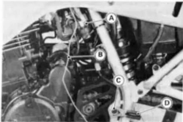
A. Positive (+) Starter Relay Terminal
B. From Booster Battery Positive (+) Terminal
C. Unpainted Metal Surface
D. From Booster Battery Negative (-) Terminal
- Connect another jumper cable from the negative (-) terminal of the booster battery to your motorcycle rear brake pedal or other unpainted metal surface. Do not use the negative (-) terminal of the battery.
▲WARNING
Do not make this last connection at the carburetor or battery. Take care that you do not touch the positive and negative cables together, and do not lean over the battery when making this last connection. Do not jump start a frozen battery. It could explode. Do not reverse polarity by connecting positive (+) to negative (−), or a battery explosion and serious damage to the electrical system may occur.
● Follow the standard engine starting procedure.
CAUTION
Do not operate the starter continuously for more than 5 seconds or the starter will overheat and the battery power will drop temporarily. Wait 15 seconds between each operation of the starter to let it cool and the battery power recover.
●After the engine has started, disconnect the jumper cables. Disconnect the negative (−) cable from the motorcycle first.
Moving Off
●Check that the side stand is up.
●Pull in the clutch lever.
●Shift into 1st gear.
●Open the throttle a little, and start to let out the clutch lever very slowly.
●As the clutch starts to engage, open the throttle a little more, giving the engine just enough fuel to keep it from stalling.

A. Shift Pedal
NOTE
The motorcycle is equipped with a side stand switch. This switch is designed so that the engine stops if the clutch is engaged with the transmission in gear when the side stand is left down.
Shifting Gears
- Close the throttle while pulling in the clutch lever.
●Shift into the next higher or lower gear. For smooth riding, shift up or down when the motorcycle is operated at the speeds shown in the table below.
WARNING
When shifting down to a lower gear, do not shift at such a high speed that the engine r/min (rpm) jumps excessively. Not only can this cause engine damage, but the rear wheel may skid and cause an accident. Downshifting should be done below 5,000 r/min (rpm) for each gear.
- Open the throttle part way, while releasing the clutch lever.
Vehicle speed when shifting
| Shifting up | km/h (mph) | Shifting down | km/h (mph) |
| 1st → 2nd | 15 (9) | 5th → 4th | 25 (15) |
| 2nd → 3rd | 25 (15) | 4th → 3rd | 20 (12) |
| 3rd → 4th | 35 (21) | 3rd → 2nd | 15 (9) |
| 4th → 5th | 45 (27) | 2nd → 1st | 15 (9) |
Braking
- Close the throttle completely, leaving the clutch engaged (except when shifting gears) so that the engine will help slow down the motorcycle.
●Shift down one gear at a time so that you are in 1st gear when you come to a complete stop. - When stopping, always apply both brakes at the same time. Normally the front brake should be applied a little more than the rear. Shift down or fully disengage the clutch as necessary to keep the engine from stalling.
● Never lock the brakes, or it will cause the tires to skid. When turning a corner, it is better not to brake at all. Reduce your speed before you get into the corner.
●For emergency braking, disregard downshifting, and concentrate on applying the brakes as hard as possible without skidding.

natural_image
Close-up of a motorcycle's front wheel and grip mechanism (no visible text or symbols)A. Front Brake Lever
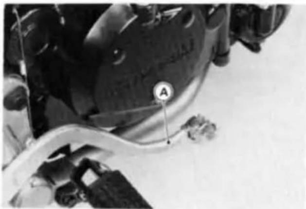
natural_image
Close-up of a mechanical component with labeled parts (A) and a cable, no readable text or symbols present.A. Rear Brake Pedal
Stopping the Engine
- Close the throttle completely.
●Shift the transmission into neutral.
●Turn the ignition key to "OFF".
●Support the motorcycle on a firm, level surface with the side stand.
●Lock the steering.
Stopping the Motorcycle in an Emergency
Your Kawasaki Motorcycle has been designed and manufactured to provide you optimum safety and convenience. However, in order to fully benefit from Kawasaki's safety engineering and craftsmanship, it is essential that you, the owner and operator, properly maintain your motorcycle and become thoroughly familiar with its operation. Improper maintenance can create a dangerous situation known as throttle failure. Two of the most common causes of throttle failure are:
- An improperly serviced or clogged air cleaner may allow dirt and dust to enter the carburetor and stick the throttle open.
- During removal of the air cleaner, dirt is allowed to enter and jam the carburetor.
In an emergency situation such as throttle failure, your vehicle may be stopped by applying the brakes and disengaging the clutch. Once this stopping procedure is initiated, the engine stop switch may be used to stop the engine. If the engine stop switch is used, turn off the ignition switch after stopping the motorcycle.
Parking
- Shift the transmission into neutral and turn the ignition key to "OFF".
●Support the motorcycle on a firm, level surface with the side stand.
CAUTION
Do not park on a soft or steeply inclined surface or the motorcycle may fall over.
- If parking inside a garage or other structure, be sure it is well ventilated and the motorcycle is not close to any source of flame or sparks; this includes any appliance with a pilot light.
▲WARNING
Gasoline is extremely flammable and can be explosive under certain conditions.
●Lock the steering to help prevent theft.
NOTE
○ When stopping near traffic at night, you can leave the taillight on for greater visibility by turning the ignition key to the P (park) position.
○Do not leave the ignition switch at P position too long, or the battery will discharge.
»»»»»»»»»»»»»»»»»»»»»»»»»»»»»»»»»»»»»»»»»»»»»»»»»»»»»»»»»»»»»»»»»»»»»»»»»»»»»»»»»»»»»»»»»»»»»»»»»»»»>
Safe Riding Technique
The points given below are applicable for everyday motorcycle use and should be carefully observed for safe and effective vehicle operation.
For safety, eye protection and a helmet are strongly recommended. Gloves and suitable footwear should also be used for added protection in case of a mishap.
A motorcycle does not provide the impact protection of an automobile, so defensive riding in addition to wearing protective apparel is extremely important. Do not let protective apparel give you a false sense of security.
Before changing lanes, look over your shoulder to make sure the way is clear. Do not rely solely on the rear view mirror; you may misjudge a vehicle's dis-
tance and speed, or you may not see it at all.
When going up steep slopes, shift to a lower gear so that there is plenty of power to spare rather than overloading the engine.
When applying the brakes, use both the front and rear brakes. Applying only one brake for sudden braking may cause the motorcycle to skid and lose control.
When going down long slopes, control vehicle speed by closing the throttle. Use the front and rear brakes for auxiliary braking.
On rainy days, rely more on the throttle to control vehicle speed and less on the front and rear brakes. The throttle should also be used judiciously to avoid skidding the rear wheel from too rapid acceleration or deceleration.
Riding at the proper rate of speed and avoiding unnecessarily fast acceleration are important not only for safety and low fuel consumption but also for long vehicle life and quieter operation.
When riding in wet conditions or on loose roadway surfaces, the ability to maneuver will be reduced. All of your actions should be smooth under these conditions. Sudden acceleration, braking or turning may cause loss of control.
On rough roads, exercise caution, slow down, and grip the fuel tank with the knees for better stability.
When quick acceleration is necessary as in passing, shift to a lower gear to obtain the necessary power.
Do not downshift at too high an r/min (rpm) to avoid damage to the engine from overrevving.
Avoiding unnecessary weaving is important to the safety of both the rider and other motorists.
Daily Safety Checks
Check the following items each day before you ride. The time required is minimal, and habitual performance of these checks will help ensure you a safe, reliable ride.
If any irregularities are found during these checks, refer to the Maintenance and Adjustment chapter or see your dealer for the action required to return the motorcycle to a safe operating condition.
WARNING
Failure to perform these checks every day before you ride may result in serious damage or a severe accident.
Fuel Adequate supply in tank, no leaks.
Engine oil Oil level between level lines.
Tires.... Air pressure (when cold):
| Front | 150 kPa (1.5 kg/cm2, 21 psi) | |
| Rear | Up to 97.5 kg(215 lb)load | 150 kPa(1.5 kg/cm2,21 psi) |
| 97.5 ~ 182 kg(215 ~ 401 lb)load | 200 kPa(2.0 kg/cm2,28 psi) | |
| Drive chain | Slack 50 ~ 60 mm (2.0 ~ 2.4 in.). |
| Nuts, bolts, fasteners | Check that steering and suspension components, axles, and all controls are properly tightened or fastened. |
| Steering | Action smooth but not loose from lock to lock.No binding of control cables. |
| Brakes | Brake pad wear: Lining thickness more than 1 mm(0.04 in.) left.No brake fluid leakage. |
| Throttle | Throttle grip play 2 ~ 3 mm (0.08 ~ 0.12 in.). |
| Clutch | Clutch lever play 2 ~ 3 mm (0.08 ~ 0.12 in.).Clutch lever operates smoothly. |
| Coolant | No coolant leakage.Coolant level between level lines (when engine is cold). |
| Electrical equipment | All lights and horn work. |
| Engine stop switch | Stops engine. |
| Side stand | Returns to its fully up position by spring tension.Return spring not weak or not damaged. |
Additional Considerations for Off Road Operation
Brakes: The importance of reliable brakes is obvious. Check to see that they are functioning properly.
Steering: Looseness in the steering can cause loss of control. Check to see that the handlebar turns freely but has no play.
Tires: Due to the extra stress to the tire on rough roads, be sure to examine their overall condition, and inflate to the proper pressure.
Drive Chain: When not adjusted properly, the severe stress on rough roads can cause damage to the sprockets and cause the chain to be thrown. Examine the chain slack and alignment, and lubricate if necessary.
Fuel: Have sufficient fuel for the high fuel consumption on rough roads.
Engine Oil: To avoid engine seizure and resulting loss of control, make certain that the oil level is at the upper level line.
Coolant: To avoid overheating, check that the coolant level is at the upper level line.
Miscellaneous: Check to see that the electrical equipment is functioning properly, all nuts and bolts are tight, and all safety related parts are in good condition.
MAINTENANCE AND ADJUSTMENT
The maintenance and adjustments outlined in this chapter are easily carried out and must be done in accordance with the Periodic Maintenance Chart to keep the motor-cycle in good running condition. The initial maintenance is vitally important and must not be neglected.
If you are in doubt as to any adjustment or vehicle operation, please ask your authorized Kawasaki dealer to check the motorcycle.
Please note that Kawasaki cannot assume any responsibility for damage resulting from incorrect maintenance or improper adjustment done by the owner.
EMISSION CONTROL INFORMATION
To protect the environment in which we all live, Kawasaki has incorporated crankcase emission (1) and exhaust emission (2) control systems in compliance with applicable regulations of the United States Environmental Protection Agency and California Air Resources Board. Additionally, Kawasaki has incorporated an evaporative emission control system (3) in compliance with applicable regulations of the California Air Resources Board on vehicle sold in California only.
1. Crankcase Emission Control System
This system eliminates the release of crankcase vapors into the atmosphere. Instead, the vapors are routed through an oil separator to the intake side of the engine. While the engine is operating, the vapors are drawn into the combustion chamber, where they are burned along with the fuel and air supplied by the carburetors.
2. Exhaust Emission Control System
This system reduces the amount of pollutants discharged into the atmosphere by the exhaust of this motorcycle. The fuel and ignition systems of this motorcycle have been carefully designed and constructed to ensure an efficient engine with low exhaust pollutant levels.
3. Evaporative Emission Control System
Vapors caused by fuel evaporation in the fuel system are not vented into the atmosphere. Instead, fuel vapors are routed into the running engine to be burned, or stored in a canister when the engine is stopped. Liquid fuel is caught by a vapor separator and returned to the fuel tank.
High Altitude Performance Adjustment Information
To improve the EMISSION CONTROL PERFORMANCE of vehicles operated above 4,000 feet, Kawasaki recommends the following Environmental Protection Agency (EPA) approved modification.
NOTE
- When properly performed, these specified modifications only are not considered to be emissions system "tampering" and vehicle performance is generally unchanged as a result.
Installation Instructions:
High altitude adjustment requires replacement of certain carburetor components. Installation of these optional parts may be performed by an authorized Kawasaki dealer, or the consumer, following repair recommendations specified in the appropriate Kawasaki Service Manual.
MAINTENANCE AND WARRANTY
Proper maintenance is necessary to ensure that your motorcycle will continue to have low emission levels. This Owner's Manual contains those maintenance recommendations for your motorcycle. Those items identified by the Periodic Maintenance Chart are necessary to ensure compliance with the applicable standards.
As the owner of this motorcycle, you have the responsibility to make sure that the recommended maintenance is carried out according to the instructions in this Owner's Manual at your own expense.
The Kawasaki Limited Emission Control System Warranty requires that you return your motorcycle to an authorized Kawasaki dealer for remedy under warranty. Please read the warranty carefully, and keep it valid by complying with the owner's obligations it contains.
You should keep a maintenance record for your motorcycle. To assist you in keeping this record, we have provided space on pages 129 through 132 of this manual where an authorized Kawasaki dealer, or someone equally competent, can record the maintenance. You should also retain copies of maintenance work orders, bills, etc., as verification of this maintenance.
TAMPERING WITH NOISE CONTROL SYSTEM PROHIBITED:
Federal law prohibits the following acts or the causing thereof: (1) the removal or rendering inoperative by any person other than for purposes of maintenance, repair, or replacement, of any device or element of design incorporated into any new vehicle for the purpose of noise control prior to its sale or delivery to the ultimate purchaser or while it is in use, or (2) the use of the vehicle after such device or element of design has been removed or rendered inoperative by any person.
Among those acts presumed to constitute tampering are the acts listed below:
• Replacement of the original exhaust system or muffler with a component not in compliance with Federal regulations.
* Removal of the muffler(s) or any internal portion of the muffler(s).
* Removal of the air box or air box cover.
• Modifications to the muffler(s) or air intake system by cutting, drilling, or other means if such modifications result in increased noise levels.
Periodic Maintenance Chart
| Operation\Frequency | Whichever comes first↓Every | *Odometer Reading km (mi) | ||||||||
| 800(500) | 5,000(3,000) | 10,000(6,000) | 15,000(9,000) | 20,000(12,000) | 25,000(15,000) | 30,000(18,000) | See Page | |||
| Emission Related | Idle speed - check † | ● | ● | ● | ● | ● | ● | ● | 81 | |
| Throttle grip play - check † | ● | ● | ● | ● | 77 | |||||
| Spark plug - clean and gap † | ● | ● | ● | ● | ● | ● | 70 | |||
| Valve clearance - check † | ● | ● | ● | ● | 71 | |||||
| Air cleaner element - clean | ● | ● | ● | ● | 74 | |||||
| Air cleaner element - replace | 5 cleanings | ● | 74 | |||||||
| Fuel system - check | ● | ● | ● | 111 | ||||||
| Evaporative emission control system (c)- check † | ● | ● | ● | ● | ● | ● | ● | 73 | ||
| Non-Emissions | Spark arrester - clean | Every 5,000 km (3,000 mi) | 85 | |||||||
| Battery electrolyte level - check † | month | ● | ● | ● | ● | ● | ● | ● | 103 | |
| Brake light switch - check † | ● | ● | ● | ● | ● | ● | ● | 95 | ||
| Brake pad wear - check † | ● | ● | ● | ● | ● | ● | 92 | |||
| Brake fluid level - check † | month | ● | ● | ● | ● | ● | ● | ● | 93 | |
| K Brake fluid - change | 2 years | ● | 94 | |||||||
| K Brake hose, connection-check † | ● | ● | ● | ● | ● | ● | - | |||
| Operation\Frequency | Whichever comes first↓ | * Odometer Reading km (mi) | ||||||||
| 800(500) | 5,000(3,000) | 10,000(6,000) | 15,000(9,000) | 20,000(12,000) | 25,000(15,000) | 30,000(18,000) | See Page | |||
| Every | ||||||||||
| Non-Emissions | K Fuel hose, connection-check † | ● | ● | ● | ● | ● | ● | - | ||
| Clutch-adjust | ● | ● | ● | ● | ● | ● | ● | 83 | ||
| K Steering-check † | ● | ● | ● | ● | ● | ● | ● | - | ||
| Balancer chain tension-adjust † | ● | ● | ● | ● | ● | ● | ● | 72 | ||
| Drive chain wear-check † # | ● | ● | ● | ● | ● | ● | 89 | |||
| K Spoke tightness and rim runout-check † | ● | ● | ● | ● | ● | ● | ● | - | ||
| Nuts, bolts, and fasteners tightness-check † | ● | ● | ● | ● | 117 | |||||
| Tire wear-check † | ● | ● | ● | ● | ● | ● | 102 | |||
| Engine oil-change | year | ● | ● | ● | ● | 63 | ||||
| Oil filter-replace † | ● | ● | ● | ● | 63 | |||||
| General Inbrication-perform | ● | ● | ● | ● | ● | ● | 113 | |||
| K Front fork oil-change | ● | - | ||||||||
| K Swingarm pivot, uni-trak linkage-lubricate | ● | ● | ● | - | ||||||
| K Coolant-change | 2 years | ● | 70 | |||||||
| FrequencyOperation | Whichevercomes first↓Every | *Odometer Reading km (mi) | ||||||||
| 800(500) | 5 000(3 000) | 10 000(6 000) | 15 000(9 000) | 20 000(12 000) | 25 000(15 000) | 30 000(18 000) | SeePage | |||
| Non-Emissions | Radiator hoses, connections--check † | year | ● | ● | ● | ● | 66 | |||
| K Steering stem bearing--lubricate | 2 years | - | ||||||||
| K Master cylinder cup and dustseal--replace | 2 years | - | ||||||||
| K Caliper piston seal and dustseal--replace | 2 years | - | ||||||||
| K Brake hose --replace | 4 years | - | ||||||||
| K Fuel hose--replace | 4 years | - | ||||||||
| Drive chain--lubricate # | Every 600 km (400 mi) | 91 | ||||||||
| Drive chain slack--check † # | Every 1,000 km (600 mi) | 86 | ||||||||
K : Should be serviced by an authorized Kawasaki dealer.
* : For higher odometer readings, repeat at the frequency interval established here.
† : Replace, add, adjust, or torque if necessary.
(c): California model only
: Service more frequently when operating in severe conditions: dusty, wet, muddy, high speed, or frequent starting/stopping.
Engine Oil
In order for the engine, transmission, and clutch to function properly, maintain the engine oil at the proper level, and change the oil and replace the oil filter in accordance with the Periodic Maintenance Chart. Not only do dirt and metal particles collect in the oil, but the oil itself loses its lubricative quality if used too long.
WARNING
Motorcycle operation with insufficient, deteriorated, or contaminated engine oil will cause accelerated wear and may result in engine or transmission seizure, accident, and injury.
Oil Level Inspection
- If the oil has just been changed, start the engine and run it for several minutes at idle speed. This fills the oil filter with oil. Stop the engine, then
wait several minutes until the oil set- tles.
CAUTION
Racing the engine before the oil reaches every part can cause engine seizure.
- If the motorcycle has just been used, wait several minutes for all the oil to drain down.
- Check the engine oil level through the oil level gauge. With the motorcycle held level, the oil level should come up between the upper and lower level lines next to the gauge.

A. Oil Level Gauge
B. Upper Level Line
C. Lower Level Line
- If the oil level is too high, remove the excess oil through the oil filler opening using a syringe or some other suitable device.
- If the oil level is too low, add the oil to reach the correct level. Use the same type and brand of oil that is already in the engine.
Oil and/or Oil Filter Change
●Warm up the engine thoroughly, and then stop it.
● Place an oil pan beneath the engine.
- Remove the engine oil drain plug.

natural_image
Close-up of a mechanical component with visible bolts and a labeled section A (no text or symbols beyond the label)A. Drain Plug
- Let the oil completely drain with the motorcycle perpendicular to the ground.
WARNING
Motor oil is a toxic substance. Dispose of used oil properly. Contact your local authorities for approved disposal methods or possible recycling.
- If the oil filter is to be changed, remove the oil filter cover bolts and take off the cover with O-ring.

A. Bolts
B. Oil Filter Cover
●Pull off the element with the element mounting pin.
●Pull the mounting pin off the element.
●Replace the element with a new one.
●Apply a little engine oil to the grommets on both side of the element, and push the mounting pin into the element. Be careful that the grommets do not slip out of place.
●Install them with the smaller end of the pin inside.

A. Element
B. Grommet
C. Mounting Pin
- Install the oil filter cover and tighten its bolts.
- After the oil has completely drained out, install the engine oil drain plug with its gasket. Proper torque for it is shown in the table.
NOTE
○ Replace the damaged gasket with a new one.
- Fill the engine up to the upper level line with a good quality motor oil specified in the table.
- Check the oil level.
Tightening Torque
Engine Oil Drain Plug: 23 N-m (2.3 kg-m, 16.5 ft-lb)
Recommended Engine Oil
Type : API SE, SF or SG : API SH, SJ or SL with JASO MA Viscosity : SAE 10W-40
Engine Oil Capacity
Capacity : 2.2 L (2.3 US qt) [when filter is not removed] : 2.5 L (2.6 US qt) [when filter is removed]
Although 10W-40 engine oil is the recommended oil for most conditions, the oil viscosity may need to be changed to accommodate atmospheric conditions in your riding area.

bar
| SAE Range | Temperature (°C) | | :--- | :--- | | 20W-50 | -18 | | 20W-40 | -16 | | 10W-50 | -14 | | 10W-40 | -12 | | 10W-30 | -10 | | 20W-50 | 32 | | 20W-40 | 30 | | 10W-50 | 34 | TK03023BZ2 CCooling System
Radiator and Cooling Fan:
Check the radiator fins for obstruction by insects or mud. Clean off any obstructions with a stream of low-pressure water.
WARNING
The cooling fan turns on automatically, even with the ignition switch off. Keep your hands and clothing away from the fan blades at all times.
CAUTION
Using high-pressure water, as from a car wash facility, could damage the radiator fins and impair the radiator's effectiveness.
Do not obstruct or deflect airflow through the radiator by installing unauthorized accessories in front of the radiator or behind the cooling fan.
Interference with the radiator airflow can lead to overheating and consequent engine damage.
Radiator Hoses:
Check the radiator hoses for cracks or deterioration, and connections for looseness in accordance with the periodic Maintenance Chart.
Coolant:
Coolant absorbs excessive heat from the engine and transfers it to the air at the radiator. If the coolant level becomes low, the engine overheats and may suffer severe damage. Check the coolant level each day before riding the motorcycle, and replenish coolant if the level is low. Change the coolant in accordance with the Periodic Maintenance Chart.
Information for Coolant
To protect the cooling system (consisting of the aluminum engine and radiator) from rust and corrosion, the use of corrosion and rust inhibitor chemicals in the coolant is essential. If coolant containing corrosion and rust inhibitor chemicals is not used, over a period of time, the cooling system accumulates rust and scale in the water jacket and radiator. This will clog up the coolant passages, and considerably reduce the efficiency of the cooling system.
WARNING
Use coolant containing corrosion inhibitors made specifically for aluminum engines and radiators in accordance with the instructions of the manufacturer. Chemicals are harmful to the human body.
Soft or distilled water must be used with the antifreeze (see below for antifreeze) in the cooling system.
CAUTION
If hard water is used in the system, it causes scale accumulation in the water passages, and considerably reduces the efficiency of the cooling system.
If the lowest ambient temperature encountered falls below the freezing point of water, use permanent antifreeze in the coolant to protect the cooling system against engine and radiator freeze-up, as well as from rust and corrosion.
Use a permanent type of antifreeze (soft water and ethylene glycol plus corrosion and rust inhibitor chemicals for aluminum engines and radiators) in the cooling system. On the mixture ratio of coolant, choose the suitable one referring to the relation between freezing point and strength directed on the container.
CAUTION
Permanent types of antifreeze on the market have anti-corrosion and anti-rust properties. When it is diluted excessively, it loses its anti-corrosion property. Dilute a permanent type of antifreeze in accordance with the instructions of the manufacturer.
NOTE
○A permanent type of antifreeze is installed in the cooling system when shipped. It is colored green and contains ethylene glycol. It is mixed at 50% and has the freezing point of -35^ C ( -31^ F).
Coolant Level Inspection
●Situate the motorcycle so that it is perpendicular to the ground.
- Check the coolant level through the coolant level gauge on the reserve tank cover. The coolant level should be between the FULL and LOW level marks.
NOTE
○Check the level when the engine is cold (room or atmospheric temperature).

A. Reserve Tank Cover
B. FULL Mark
C. LOW Mark
D. Right Air Scoop
- If the amount of coolant is insufficient, remove the right air scoop, unscrew the cap from the reserve tank, and add coolant through the filler opening to the FULL mark.
● Install the cap and right air scoop.
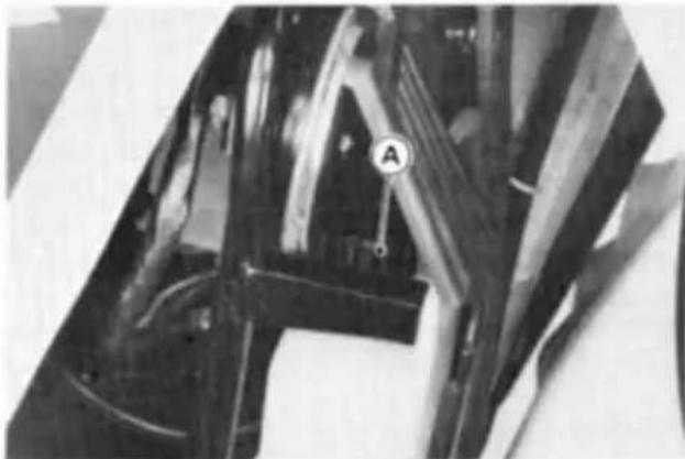
natural_image
Close-up of mechanical components with no visible text or symbolsA. Reserve Tank Cap
NOTE
○In an emergency you can add water alone to the coolant reserve tank, however it must be returned to the correct mixture ratio by the addition of antifreeze concentrate as soon as possible.
CAUTION
If coolant must be added often, or the reserve tank completely runs dry, there is probably leakage in the system. Have the cooling system inspected by your authorized Kawasaki dealer.
Coolant Change
Have the coolant changed by an authorized Kawasaki dealer.
Spark Plug
Remove the fuel tank and unscrew the spark plug.
The standard spark plug is shown in the table. The spark plug should be taken out in accordance with the Periodic Maintenance Chart for cleaning, inspection, and resetting of the plug gap.
Maintenance
If the plug is oily or has carbon built up on it, have it cleaned, preferably in a sand-blasting device, and then clean off any abrasive particles. The plug may also be cleaned using a high flash-point solvent and a wire brush or other suitable tool. Measure the gap with a wire-type thickness gauge, and adjust the gap if incorrect by bending the outer electrode. If the spark plug electrodes are corroded or damaged, or if the insulator is cracked, replace the plug. Use the standard plug.

Spark Plug
| Standard Plug | NGK DPR8EA-9 or ND X24EPR-U9 |
| Plug Gap | 0.8 ~ 0.9 mm(0.032 ~ 0.036 in) |
| Tightening Torque | 14 N-m(1.4 kg-m, 10.0 ft-lb) |
Valve Clearance
Valve and valve seat wear decreases valve clearance, upsetting valve timing.
| CAUTION |
| If valve clearance is left unadjusted, wear will eventually cause the valves to remain partly open; which lowers performance, burns the valves and valve seats, and may cause serious engine damage. |
Valve clearance for each valve should be checked and adjusted in accordance with the Periodic Maintenance Chart.
Inspection and adjustment should be done only by a competent mechanic following the instructions in the Service Manual.
Balancer Chain
Wear of the balancer chain and the chain guide develops slack between them. Adjust the balancer chain tensioner in accordance with the Periodic Maintenance Chart.
CAUTION
If the balancer chain is left unadjusted, the developed slack will make noise and may result in engine damage.
Chain Tensioner Adjustment
- Remove the tensioner cap and loosen the tensioner bolt a few turns.

A. Cap
B. Tensioner Bolt
●Tighten back the bolt and install the cap in the original position.
Evaporative Emission Control System (California model only)
This system routes fuel vapors from the fuel system into the running engine or stores the vapors in a canister when the engine is stopped. Although no adjustments are required, a thorough visual inspection must be made at the intervals specified by the Periodic Maintenance Chart.
Inspection
- Check that the hoses are securely connected.
●Replace any kinked, deteriorated, or damaged hoses.
VACUUM HOSE ROUTING DIAGRAM

Air Cleaner
A clogged air cleaner restricts the engine's air intake, increasing fuel consumption, reducing engine power, and causing spark plug fouling.
The air cleaner element must be cleaned and replaced in accordance with the Periodic Maintenance Chart. In dusty areas, the element should be cleaned more frequently than the recommended interval. After riding through rain or on muddy roads, the element should be cleaned immediately. The element should be replaced if it is damaged.

A. Element
B. Wing Bolt
- Remove the element from the frame.
Element Removal
- Remove the right side cover.
●Unscrew the air cleaner cover screw and remove the air cleaner cover. - Remove the wing bolt, and take out the element.

A. Element
B. Frame
● Put a clean, lint-free towel over the air cleaner housing to keep dirt or other foreign material from entering.
- Inspect the element material for damage. If any part of the element is damaged, the element must be replaced.
▲WARNING
If dirt or dust is allowed to pass through into the carburetor, the throttle may become stuck, possibly causing accident.
CAUTION
If dirt gets through into the engine, excessive engine wear and possibly engine damage will occur.
NOTE
○Element installation is performed in the reverse order of removal.
Element Cleaning
● Clean the element in a bath of a high flash-point solvent.
●Dry the element with compressed air or by shaking it.
●After cleaning, saturate the element with SE, SF or SG class SAE 10W40 motor oil.
- Press the element against a work-bench to squeeze out the excess oil, then wrap it in a clean rag and squeeze it as dry as possible.
WARNING
Clean the element in a well ventilated area, and take care that there are no sparks or flame anywhere near the working area; this includes any appliance with a pilot light. Do not use gasoline or a low flash-point solvent to clean the element. A fire or explosion could result.
Oil Draining
- Inspect the transparent reservoir below the swingarm pivot section on the right side of the motorcycle to see if any oil has run down from the air cleaner housing.

A. Reservoir
B. Drain Hose
C. Plug
- If there is any oil in the reservoir, remove the plug from the lower end of the drain hose and drain the oil.
▲WARNING
Be sure to install the plug in the drain hose after draining. Oil on tires will make them slippery and can cause an accident and injury.
Throttle Grip
The throttle grip controls the throttle valves. If the throttle grip has excessive play due to either cable stretch or maladjustment, it will cause a delay in throttle response, especially at low engine speed. Also, the throttle valves may not open fully at full throttle. On the other hand, if the throttle grip has no play, the throttle will be hard to control, and the idle speed will be erratic. Check the throttle grip play in accordance with the Periodic Maintenance Chart, and adjust the play if necessary.
Inspection
- Check that there is 2 \~ 3 mm (0.08 \~ 0.12 in.) throttle grip play when lightly turning the throttle grip back and forth.
●If there is improper play, adjust it.

natural_image
Close-up of a mechanical device with labeled parts A and B, showing no readable text or symbols beyond labels.A. Throttle Grip
B. 2 \~ 3 mm (0.08 \~ 0.12 in)
Adjustment
● Loosen the locknuts at the upper end of the throttle cables, and screw both throttle cable adjusting nuts in completely so as to give the throttle grip plenty of play.
●Turn out the decelerator cable adjusting nut until there is no play when the throttle grip is completely closed. Tighten the locknut.

A. Accelerator Cable
B. Decelerator Cable
C. Adjusting Nuts
D. Locknuts
●Turn the accelerator cable adjusting nut until 2 \~ 3 mm (0.08 \~ 0.12 in) of throttle grip play is obtained. Tighten the locknut.
NOTE
○If the throttle cables cannot be adjusted by using the cable adjusting nuts at the upper end of the throttle cables, use the cable adjusters at the lower end of the throttle cables (at the carburetor). Do not forget to securely tighten the adjuster locknuts.

A. Accelerator Cable
B. Decelerator Cable
C. Adjusting Nuts
D. Locknuts
Be sure the upper ends of the outer cables are fully seated in their adjusting nuts, or they could slip into place later, creating enough grip play to prevent throttle operation, resulting in a hazardous riding condition.
●Start the engine.
●Turn the handlebar from side to side while idling the engine.
★If idle speed varies, the throttle cables may be poorly routed or they may be damaged.
● Correct any problem before operating the motorcycle.
WARNING
WARNING
Operation with an improperly adjusted, incorrectly routed, or damaged cable could result in an unsafe riding condition.
Choke Lever
By pushing the choke lever, the carburetor provides a rich starting mixture that is necessary to enable easy starting when the engine is cold.
If starting difficulty or rich fuel mixture trouble occurs, inspect the choke lever, and adjust if necessary.
Inspection
- Check that the choke lever returns properly and that the inner cable sides smoothly. If there is any irregularity, have the choke cable checked by an authorized Kawasaki dealer.
●Push the choke lever back all the way to its released position.
●Determine the amount of choke cable play at the upper end of the choke cable. Pull out and push in the outer cable; the amount of cable travel is the amount of cable play.

A. Choke Lever
●The proper amount of play is 2 \~ 3 mm (0.08 \~ 0.12 in.). If there is too much or too little play, adjust the choke cable.
Adjustment
●Loosen the locknut, and turn the adjusting nut until the cable has the proper amount of play.

A. Locknut
C. 2 \~ 3 mm
B. Adjusting Nut
(0.08 \~ 0.12 in.)
●Tighten the locknut after adjustment.
Carburetor
The following procedure covers the idle speed adjustment, which should be performed in accordance with the Periodic Maintenance Chart or whenever the idle speed is disturbed.
Adjustment
●Start the engine, and warm it up thoroughly.
- Adjust the idle speed to 1,200 \~ 1,400 r/min (rpm) by turning the idle adjusting screw.

natural_image
Close-up of mechanical components with no visible text or symbolsA. Idle Adjusting Screw
- Open and close the throttle a few times to make sure that the idle speed does not change. Readjust if necessary.
●With the engine idling, turn the handlebar to each side. If handlebar movement changes the idle speed, the throttle cables may be improperly adjusted or incorrectly routed, or they may be damaged. Be sure to correct any of these conditions before riding.
WARNING
Operation with damaged cables could result in an unsafe riding condition.
Clutch
Due to friction plate wear and clutch cable stretch over a long period of use, the clutch must be adjusted in accordance with the Periodic Maintenance Chart.
WARNING
To avoid a serious burn, never touch a hot engine or exhaust pipe during clutch adjustment.
Inspection
- Check that the clutch lever has 2 \~ 3 mm (0.08 \~ 0.12 in) of play as shown in the figure.
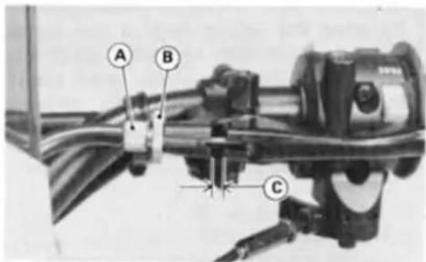
A. Adjuster
B. Locknut
C. 2 \~ 3 mm (0.08 \~ 0.12 in)
If the play is incorrect, adjust the lever play as follows.
Adjustment
●Loosen the locknut at the clutch lever.
●Turn the adjuster so that the clutch lever will have 2 \~ 3 mm (0.08 \~ 0.12 in) of play.
▲WARNING
Be sure the upper end of the clutch outer cable is fully seated in its fitting, or it could slip into place later, creating enough cable play to prevent clutch disengagement, resulting in a hazardous riding condition.
●Tighten the locknut.
- If it cannot be done, use the mounting nuts at the lower end of the cable.

natural_image
Close-up of a mechanical assembly with hoses and components (no visible text or symbols)A. Mounting Nuts
B. Clutch Cable
NOTE
○ After the adjustment is made, start the engine and check that the clutch does not slip and that it releases properly.
○For minor corrections, use the adjuster at the clutch lever.
Spark Arrester
This motorcycle is equipped with a spark arrester approved for off-road use by the U.S. Forest Service. It must be properly maintained to ensure its efficiency. In accordance with the Periodic Maintenance Chart, clean the spark arrester.
CAUTION
The spark arrester must be installed correctly and functioning properly to provide adequate fire protection.
Spark Arrester Cleaning
▲WARNING
To avoid burns, wear gloves while cleaning the spark arrester. Since the engine must be run during this procedure, the muffler will become hot.
- Remove the drain plugs on the muffler.

natural_image
Close-up of a motorcycle's front wheel and side panel, showing tire, suspension, and license plate (no readable text or symbols)A. Drain Plugs
● In an open area away from combustible materials, start the engine with the transmission in neutral.
● Raise and lower engine speed while tapping on the muffler with a rubber mallet until carbon particles are purged from the muffler.
WARNING
Do not run the engine in a closed area. Exhaust gases contain carbon monoxide; a colorless, odorless, poisonous gas. Breathing exhaust gas leads to carbon monoxide poisoning, asphyxiation, and death.
- Stop the engine.
● Install the drain plugs.
Drive Chain
The drive chain must be checked, adjusted, and lubricated in accordance with the Periodic Maintenance Chart for safety and to prevent excessive wear. If the chain becomes badly worn or maladjusted – either too loose or too tight – the chain could jump off the sprockets or break.
▲WARNING
A chain that breaks or jumps off the sprockets could snag on the engine sprocket or lock the rear wheel, severely damaging the motorcycle and causing it to go out of control.
Chain Slack Inspection
- Set the motorcycle up on its side stand.
- Rotate the rear wheel to find the position where the chain is tightest, measure the maximum chain slack by
pulling up and pushing down the chain midway between the engine sprocket and rear wheel sprocket.

natural_image
Mechanical assembly diagram showing a chain with labeled parts and an arrow indicating motion direction (no readable text or symbols)A. 50 \~ 65 mm (2.0 \~ 2.6 in)
- If the drive chain is too tight or too loose, adjust it so that the chain slack will be within the standard value.
Drive Chain Slack
| Standard | 50 ~ 60 mm (2.0 ~ 2.4 in) |
| Too tight | less than 50 mm (2.0 in) |
| Too loose | more than 65 mm (2.6 in) |
Chain Slack Adjustment
● Loosen the left and right chain adjuster locknuts.
- Remove the cotter pin, and loosen the axle nut.

A. Axle Nut
B. Cotter Pin
C. locknut
D. Adjusting Nut
- If the chain is too tight, back out the left and right chain adjusting nuts evenly, and kick the wheel forward until the chain is too loose.
●Turn in both chain adjusting nuts evenly until the drive chain has the correct amount of slack. To keep the chain and wheel properly aligned, the notch on the left chain adjuster should align with the same swingarm
mark that the right chain adjuster notch aligns with.

A. Marks
B. Notch
C. Locknut
D. Adjusting Nut
NOTE
○ Wheel alignment can also be checked using the straightedge or string method.
▲WARNING
Misalignment of the wheel will result in abnormal wear, and may result in an unsafe riding condition.
●Tighten both chain adjuster locknuts.
●Tighten the axle nut to the specified torque.
Tightening Torque
| Axle Nut : | 93 N-m(9.5 kg-m, 69 ft-lb) |
- Rotate the wheel, measure the chain slack again at the tightest position, and readjust if necessary.
●Insert a new cotter pin through the axle nut and axle, and spread its ends.
WARNING
If the axle nut is not securely tightened or the cotter pin is not installed, an unsafe riding condition may result.
Wear Inspection
●Stretch the chain taut either by using the chain adjusters, or by hanging a 10 kg (20 lb) weight on the chain.
●Measure the length of 20 links on the straight part of the chain from pin center of the 1st pin to pin center of the 21st pin. Since the chain may wear unevenly, take measurements at several places.

natural_image
Close-up of a motorcycle's front wheel and drivetrain with labeled parts (no readable text beyond labels)A. Measure
B. Weight
- If the length exceeds the service limit, the chain should be replaced.
Drive Chain 20-Link Length
Service Limit: 323 mm (12.7 in).
WARNING
For safety, use only the standard chain. It is an endless type and should not be cut for installation; have it installed by an authorized Kawasaki dealer.
- Rotate the rear wheel to inspect the drive chain for damaged rollers, and loose pins and links.
●Also inspect the sprockets for unevenly or excessively worn teeth, and damaged teeth.
NOTE
○ Sprocket wear is exaggerated for illustration. See Service Manual for wear limits.

- If there is any irregularity, have the drive chain and/or the sprockets replaced by an authorized Kawasaki dealer.
Lubrication
Lubrication is also necessary after riding through rain or on wet roads, or any time that the chain appears dry. A heavy oil such as SAE 90 is preferred to a lighter oil because it will stay on the
chain longer and provide better lubrication.
●Apply oil to the sides of the rollers so that it will penetrate to the rollers and bushings. Apply oil to the O-rings so that the O-rings will be coated with oil. Wipe off any excess oil.
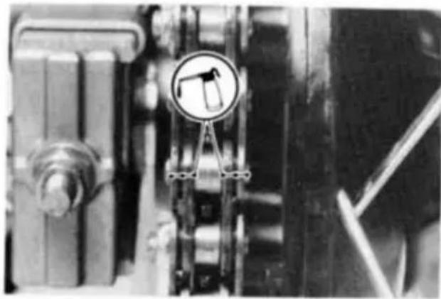
natural_image
Close-up of industrial machinery components with a circular warning sign (no readable text or symbols)- If the chain is especially dirty, clean it using diesel oil or kerosine and then apply oil as described above.
Brakes
Brake Wear Inspection
In accordance with the Periodic Maintenance Chart, inspect the brakes for wear. For each front and rear disc brake caliper, if the thickness of either pad is less than 1 mm (0.04 in), replace both pads in the caliper as a set. Pad replacement should be done by an authorized Kawasaki dealer.
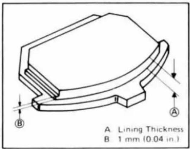
Disc Brake Fluid:
In accordance with the Periodic Maintenance Chart, inspect the brake fluid level in both the front and rear brake fluid reservoirs and change the brake fluid. The brake fluid should also be changed if it becomes contaminated with dirt or water.
Fluid Requirement
Use heavy-duty brake fluid only from a container marked D O T 3 or D O T 4.
NOTE
Brake fluid of DOT4 is installed in the brake system when shipped.
CAUTION
Do not spill brake fluid onto any painted surface.
Do not use fluid from a container that has been left open or that has been unsealed for a long time.
Check for fluid leakage around the fittings.
Check brake hoses for damage.
Fluid Level Inspection
●The brake fluid level in the front brake fluid reservoir must be kept above the line (lower level line) next to the gauge and that in the rear brake fluid reservoir (located under the right side cover) must be kept between the upper and lower level lines (reservoirs held horizontal).

A. Front Brake Fluid Reservoir
B. Upper Level
C. Lower Level

A. Rear Brake Fluid Reservoir
B. Upper Level Line
C. Lower Level Line
D. Filler Cap
- If the fluid level in either reservoir is lower than the lower level line, check for fluid leaks in the brake lines, and fill the reservoir to the upper level line.
▲WARNING
Do not mix two brands of brake fluid. Change the brake fluid in the brake line completely if the brake fluid must be refilled but the type and brand of the brake fluid that is already in the reservoir are unidentified.
Fluid Change
Have the brake fluid changed by an authorized Kawasaki dealer.
Front and Rear Brakes:
Disc and disc pad wear is automatically compensated for and has no effect on the brake lever or pedal action. So there are no parts that require adjustment on the front and rear brakes.
WARNING
If the brake lever or pedal feels mushy when it is applied, there might be air in the brake lines or the brake may be defective. Since it is dangerous to operate the motorcycle under such conditions, have the brake checked immediately by an authorized Kawasaki dealer.
Brake Light Switches
When either the front or rear brake is applied, the brake light goes on. The front brake light switch requires no adjustment, but the rear brake light switch should be adjusted in accordance with the Periodic Maintenance Chart.
Inspection
●Turn the ignition key to "ON".
●The brake light should go on when the front brake is applied.
- If it does not, ask your authorized Kawasaki dealer to inspect the front brake light switch.
- Check the operation of the rear brake light switch by depressing the brake pedal. The brake light should go on after about 15 mm (0.6 in) of pedal travel.
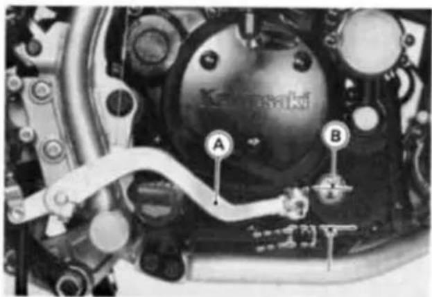
A. Brake Pedal
B. 15 mm (0.6 in)
- If it does not, adjust the rear brake light switch.
Adjustment
●To adjust the rear brake light switch, move the switch up or down by turning the adjusting nut.
CAUTION
To avoid damaging the electrical connections inside the switch, be sure that the switch body does not turn during adjustment.

A. Rear Brake Light Switch
B. Adjusting Nut
C. Lights sooner.
D. Lights later.
Front Fork
Air Pressure:
The standard air pressure in the front fork legs is atmospheric pressure. The air pressure in the fork legs increases as the fork heats up, so the fork action will get stiffer as the vehicle operation progresses.
● Using the jack under the frame, stabilize the motorcycle.
● Place a stand or block under the engine so that the front wheel is raised off the ground.
- Remove the air valve cap off the top of the front fork legs.
● Push the valve cores in to release air pressure.
NOTE
○Addition of air pressure is not recommended since atmospheric pressure is the most suitable setting for all ranges of riding.
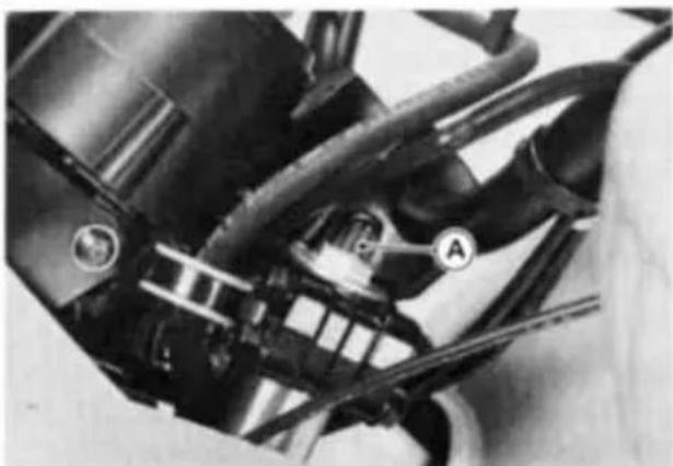
natural_image
Close-up of mechanical components with visible wiring and a labeled component (A), no readable text or symbols present.A. Air Valve Cap
Rear Shock Absorber
The rear shock absorber can be adjusted by changing the spring preload and rebound damping force for various riding and loading conditions.
Before making any adjustments, however, read the following procedures:
Spring Preload Adjustment
The spring preload adjuster on the rear shock absorber has 5 positions.
- Remove the left side cover.
- Remove the band and take out the canister (California model).

natural_image
Close-up of mechanical components with hoses and a labeled component (A), no readable text or symbols present.A. Canister
- Adjust the spring preload by turning the adjuster counterclockwise to get softer or clockwise to get harder.

A. Rear Shock Absorber
B. Adjuster
| Position | 1 | 2 | 3 | 4 | 5 |
| Spring Action | → Stronger | ||||
Rebound Damping Force Adjustment
The rebound damping force adjuster on the bottom of the rear shock absorber has 4 positions. The numbers on the adjuster show the setting position.

A. Rebound Damping Force Adjuster
B. Number
●Turn the adjuster until the desired number faces outward with a click in accordance with the following table:
| Position | I | II | III | III |
| Rebound Damping Force | → Larger | |||
NOTE
When adjusting the rebound damping force, remove the cover and turn the adjuster to the desired number until you feel a click.
Rear Shock Absorber Setting
To obtain stable handling and a suitable ride, adjust the spring preload or rebound damping force for different road and loading conditions as indicated. For instance, the initial setting (spring position is 1; rebound damping force adjuster position is 1) is softest and designed for an average-build rider of 68 kg (150 lb) with no passenger and no accessories. Ordinarily, the heavier the total load becomes, the harder the suspension should be set.
Setting Table for Spring Preload and Rebound Damping Force
| Riding condition Adjuster | An average-build rider | A rider and a passenger | A rider and a passenger with load |
| Spring preload | 1 or 2 | 2 or 3 | 3, 4, or 5 |
| Damping force | 1 or II | II or III | III or III |
○ : Standard setting (number) is identified with a circle marking.
Wheels
Tires:
Payload and Tire Pressure
Failure to maintain proper inflation pressures or observe payload limits for your tires may adversely affect handling and performance of your motorcycle and can result in loss of control. The maximum recommended load in addition to vehicle weight is 182 kg (401 lb), including rider, passenger, baggage, and accessories.
- Check the tire pressure often, using an accurate gauge.
NOTE
○ Measure the tire pressure when the tires are cold (that is, when the motorcycle has not been ridden more than a mile during the past 3 hours).
○Tire pressure is affected by changes in ambient temperature and altitude, and so the tire pressure should be checked and adjusted when your riding in-
volves wide variations in temperature or altitude.

natural_image
Close-up of a hand holding a small mechanical component with a labeled point A (no visible text or symbols)A. Tire Pressure Gauge
Tire Air Pressure (when cold)
| Front | 150 kPa (1.5 kg/cm2,21 psi) | |
| Rear | Up to 97.5 kg(215 lb) load | 150 kPa(1.5 kg/cm2,21 psi) |
| 97.5 ~ 182 kg(215 ~ 401 lb)load | 200 kPa(2.0 kg/cm2,28 psi) | |
Tire Wear, Damage
As the tire tread wears down, the tire becomes more susceptible to puncture and failure. An accepted estimate is that 90% of all tire failures occur during the last 10% of tread life (90% worn). So it is false economy and unsafe to use the tires until they are bald.
●In accordance with the Periodic Maintenance Chart, measure the depth of the tread with a depth gauge, and replace any tire that has worn down to the minimum allowable tread depth.

A. Tire Depth Gauge
Minimum Tread Depth
Front and Rear 2 mm (0.08 in)
●Visually inspect the tire for cracks and cuts, replacing the tire in case of bad damage. Swelling or high spots indicate internal damage, requiring tire replacement.
- Remove any imbedded stones or other foreign particles from the tread.
NOTE
○Have the wheel balance inspected whenever a new tire is installed.
▲WARNING
To ensure safe handling and stability, use only the recommended standard tires for replacement, inflated to the standard pressure.
Standard Tire
| Front | ○90/90-21 54SDUNLOP K750 |
| Rear | ○130/80-17 65SDUNLOP K750 |
WARNING
New tires are slippery and may cause loss of control and injury.
A break-in period of 160 km (100 miles) is necessary to establish normal tire traction. During break-in, avoid sudden and maximum braking and acceleration, and hard cornering.
Battery
WARNING
Battery posts, terminals and related accessories contain lead and lead compounds. Wash hands after handling.
Battery Electrolyte Level Inspection
The battery electrolyte level must be kept between the upper and lower level lines. Check the electrolyte level in each cell in accordance with the Periodic Maintenance Chart.
- Remove the battery from the motorcycle (see Battery Removal).
- Check that the electrolyte level in each cell is between the upper and lower level lines.

A. Filler Caps
B. Upper Level Line
C. Lower Level Line
- If the electrolyte level is low in any cell, fill with distilled water as follows.
- Remove the battery filler caps and fill with distilled water until the electrolyte level in each cell reaches the upper level line.
CAUTION
Add only distilled water to the battery. Ordinary tap water is not a substitute for distilled water and will shorten the life of the battery.
Battery Charging
- Remove the battery from the motorcycle (see Battery Removal).
CAUTION
Always remove the battery from the motorcycle for charging. If the battery is charged while still installed, battery electrolyte may spill and corrode the frame or other parts of the motorcycle.
● Before charging, check the electrolyte level in each cell. If the electrolyte level is low in any cell, fill to above the lower level line but not up to the
upper level line since the level rises during charging.
- Remove the caps from all the cells, and connect the battery charger leads to the battery terminals (red to +, black to -).
▲WARNING
Because the battery gives off an explosive gas mixture of hydrogen and oxygen, keep any sparks or open flame away from the battery during charging. When using a battery charger, connect the battery to the charger before turning on the charger. This procedure prevents sparks at the battery terminals which could ignite any battery gases.

A. Battery Charger
C. (-) Terminal
B. Filler Caps
D. (+) Terminal
●Charge the battery at a rate that is 1/10th of the battery capacity. For example, the charging rate for a 10Ah battery would be 1.0 ampere.
CAUTION
Do not use a high rate battery charger, as is typically employed at automotive service stations, unless the charging rate can be reduced to the level required for motorcycle batteries. Charging the battery at a rate higher than specified may ruin the battery. Charging at a high rate causes excess heat which can warp the plates and cause internal shorting. Higher than normal charging rates also cause the plates to shed active material. Deposits will accumulate, and can cause internal shorting. If the temperature of the electrolyte rises above 45°C (115°F) during charging, reduce the charging rate to lower the temperature, and increase charging time proportionately.
●After charging, check the electrolyte level in each cell. If the level has fal-
len, add distilled water to bring it back up to the upper level line.
●Install the caps on the cells.
●Install the battery.
Battery Removal
- Remove the seat and left side cover.
● Disconnect the leads from the battery, first from the (−) terminal and then the (+) terminal.

natural_image
Close-up of automotive battery pack with labeled components (A and B), no readable text or symbols beyond labelsA. (+) Terminal
B. (-) Terminal
●Unscrew the battery holder screw and remove the battery holder.
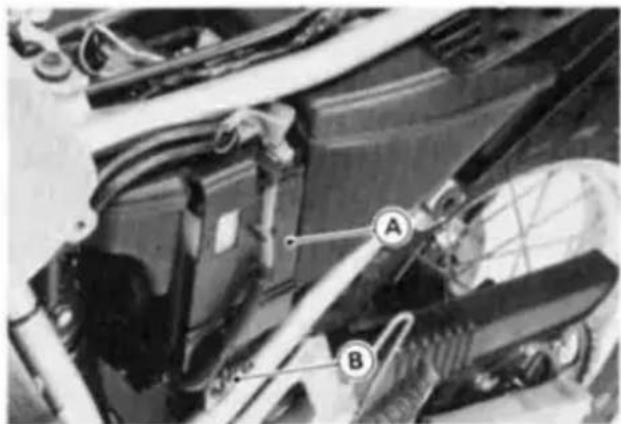
A. Battery Holder
B. Screw
●Take the battery out of the case.
● Clean the battery using a solution of baking soda and water. Be sure that the lead connections are clean.
Battery Installation
●Put the battery in the battery case, and route the battery vent hose as shown on the caution label.
●Install the battery holder.
- Connect the capped lead to the (+) terminal, and then connect the black/yellow lead to the (-) terminal.
NOTE
○ Install the battery in the reverse order of the Battery Removal.
●Put a light coat of grease on the terminals to prevent corrosion.

natural_image
Close-up of a car's engine compartment with visible hoses and a valve (no text or symbols)A. Grease.
● Cover the (+) terminal with its protective cap.
CAUTION
Make sure the battery vent hose is kept away from the drive system and exhaust system. Battery electrolyte can corrode and dangerously weaken the drive system. Do not let the vent hose become folded, pinched, or melted by the exhaust system. An unvented battery will not keep a charge and it may crack from built-up gas pressure.
CAUTION
Installing the (-) cable to the (+) terminal of the battery or the (+) cable to the (-) terminal of the battery can seriously damage the electrical system.
Headlight Beam
Horizontal Adjustment
The headlight beam is adjustable horizontally. If not properly adjusted horizontally, the beam will point to one side rather than straight ahead.
●Turn the adjusting screw on the head-light rim in or out until the beam points straight ahead. Turning the adjusting screw clockwise makes the headlight beam point to the right.

A. Adjusting Screw
Vertical Adjustment
The headlight beam is adjustable vertically. If adjusted too low, neither low nor high beam will illuminate the road far enough ahead. If adjusted too high, the high beam will fail to illuminate the road close ahead, and the low beam will blind oncoming drivers.
●Loosen the lower headlight bolt, and adjust the headlight vertically.
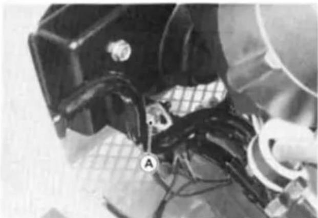
natural_image
Close-up of mechanical components with no visible text or symbolsA. Lower Headlight Bolt
●Tighten the lower headlight bolt.
NOTE
On high beam, the brightest point should be slightly below horizontal. The proper angle is 0.4 degrees below horizontal. This is a 50 mm (2 in.) drop at 7.6 m (25 ft) measured from the center of the headlight, with the motorcycle on its wheels and the rider seated.

Fuses
The fuse case is located on the battery holder. If a fuse fails during operation, inspect the electrical system to determine the cause, and then replace it with a new fuse of proper amperage.

natural_image
Close-up of a car engine bay with labeled components A and B, showing wiring and battery (no readable text or symbols beyond labels)A. Fuse Case
B. Spare Fuse
WARNING
Do not use any substitute for the standard fuse.
Replace the blown fuse with a new one of the correct capacity.
Fuel System
Accumulation of moisture or sediment in the fuel system will restrict the flow of fuel and cause carburetor malfunction. The system should be checked in accordance with the Periodic Maintenance Chart.
WARNING
Gasoline is extremely flammable and can be explosive under certain conditions. Turn the ignition key to "OFF". Do not smoke. Make sure the area is well ventilated and free from any source of flame or sparks; this includes any appliance with a pilot light. Make sure the engine is cold before working. Wipe any fuel off the engine before starting it.
Inspection
- Connect a suitable hose to the fitting at the bottom of the carburetor float bowl.
●Run the lower end of the drain hose into a suitable container.
●Turn out the drain screw a few turns to drain the carburetor, and check to see if water or dirt has accumulated in the carburetor.
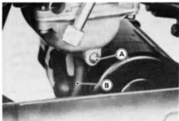
A. Drain Screw
B. Suitable Hose
●Tighten the drain screw.
- Remove the suitable hose from the carburetor float bowl.
NOTE
○If any water or dirt appears during the above operation, have the fuel system checked by a competent mechanic following the procedure in the Service Manual.
General Lubrication
Lubricate the points shown below, with either motor oil or regular grease, in accordance with the Periodic Maintenance Chart or whenever the vehicle has been operated under wet or rainy conditions.
Before lubricating each part, clean off any rusty spots with rust remover and wipe off any grease, oil, dirt, or grime.
NOTE
○A few drops of oil are effective to keep bolts and nuts from rusting and sticking. This makes removal easier. Badly rusted nuts, bolts, etc., should be replaced with new ones.
Apply motor oil to the following pivots:
○Side Stand
○ Clutch Lever
○ Front Brake Lever
○ Rear Brake Pedal
○ Rear Brake Rod Joint
Lubricate the following cables with a pressure cable luber:
○ Clutch Inner Cable
○Throttle Inner Cables

natural_image
Illustration of two hands holding a tool with a pen, no text or symbols presentApply grease to the following points:
- Clutch Inner Cable Upper End - Throttle Inner Cable Upper Ends
* ○Speedometer Inner Cable
* Grease the lower part of the inner cable sparingly.
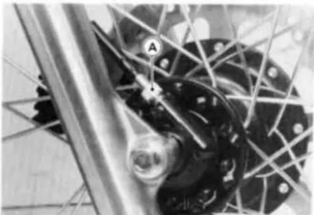
natural_image
Close-up of a bicycle wheel assembly with visible components and structural lines (no text or symbols)A. Speedometer Cable

natural_image
Close-up of mechanical components with intersecting rods and a central circular component (no visible text or symbols)A. Grease
NOTE
○After connecting the cables, adjust them.
Insert the speedometer inner cable into the speedometer gear housing while turning the wheel so that the slot in the end of the cable will seat in the tongue of the speedometer pinion.
Cleaning Your Motorcycle
General Precautions
Frequent and proper care of your Kawasaki motorcycle will enhance its appearance, optimize overall performance, and extend its useful life. Covering your motorcycle with a high quality, breathable motorcycle cover will help protect its finish from harmful UV rays, pollutants, and reduce the amount of dust reaching its surfaces.
-
Be sure the engine and exhaust are cool before washing.
● Avoid applying degreaser to seals, brake pads, and tires.
● Always use non-abrasive wax and cleaner/polisher.
● Avoid all harsh chemicals, solvents, detergents, and household cleaning products such as ammonia-based window cleaners.
● Gasoline, brake fluid, and coolant will damage the finish of painted and plastic surfaces: wash them off immediately.
● Avoid wire brushes, steel wool, and all other abrasive pads or brushes. -
Use care when washing the windshield, headlight cover, and other plastic parts as they can easily be scratched.
● Avoid using pressure washers; water can penetrate seals and electrical components and damage your motorcycle.
● Avoid spraying water in delicate areas such as in air intakes, carburetors, brake components, electrical components, muffler outlets, and fuel tank openings.
Washing your motorcycle
● Rinse your bike with cold water from a garden hose to remove any loose dirt.
● Mix a mild neutral detergent (designed for motorcycles or automobiles) and water in bucket. Use a soft cloth or sponge to wash your motorcycle. If needed, use a mild degreaser to remove any oil or grease build up.
● After washing, rinse your motorcycle thoroughly with clean water to remove any residue (residue from the detergent can damage parts of your motorcycle).
- Use a soft cloth to dry your motorcycle. As you dry, inspect your motorcycle for chips and scratches. Do not let the
water air dry as this can damage the painted surfaces.
- Start the engine and let it idle for several minutes. The heat from the engine will help dry moist areas.
● Carefully ride your motorcycle at a slow speed and apply the brakes several times. This helps dry the brakes and restores them to normal operating performance.
● Lubricate the drive chain to prevent rusting.
NOTE
After riding in an area where the roads are salted or near the ocean, immediately wash your motorcycle with cold water. Do not use warm water as it accelerates the chemical reaction of the salt. After drying, apply a corrosion protection spray on all metal and chrome surfaces to prevent corrosion.
Painted Surfaces
After washing your motorcycle, coat painted surfaces, both metal and plastic, with a commercially available motorcycle/automotive wax. Wax should be applied once every three months or as conditions require. Avoid surfaces with "satin" or "flat" finishes. Always use non-abrasive products and apply them according to the instructions on the container.
Windshield and Other Plastic Parts
After washing use a soft cloth to gently dry plastic parts. When dry, treat the windshield, headlight lens, and other non-painted plastic parts with an approved plastic cleaner/polisher product.
CAUTION
Plastic parts may deteriorate and break if they come in contact with chemical substances or household cleaning products such as gasoline, brake fluid, window cleaners, thread-locking agents, or other harsh chemicals. If a plastic part comes in contact with any harsh chemical substance, wash it off immediately with water and a mild neutral detergent then inspect for damage. Avoid using abrasive pads or brushes to clean plastic parts, as they will damage the part's finish.
Chrome and Aluminum
Chrome and uncoated aluminum parts can be treated with a chrome/aluminum polish. Coated aluminum should be washed with mild neutral detergent and finished with a spray polish. Aluminum wheels, both painted and unpainted can be cleaned with special non-acid based wheel spray cleaners.
Cleaning of Exhaust System:
| CAUTION |
| To prevent surface damage, do not clean the exhaust system with chrome polishes or cleaners. Do not use waxes containing cleaners or abrasive cutting agents. Always use a soft cloth when washing and drying the system. |
Washing
The exhaust system must be cool before washing to prevent water spotting.
●Prepare a mixture of water and mild soap, such as dishwashing detergent. Do not use a high alkaline content soap as commonly found at commercial car washes because it leaves a residue.
●Wash the exhaust system with a soft cloth. Do not use an abrasive scouring pad or steel wool. They will damage the finish.
● Rinse the exhaust system thoroughly.
Drying
●Dry the exhaust system completely with a soft cloth. Do not run the engine to dry the system or spotting will occur.
Protecting
- When the system is dry, apply a light coat of WD40, LPS-1, or Bel-Ray 6 in 1 multipurpose oil.
●Wipe off the excess oil
●The system can be waxed instead of oiled. Use a carnauba type paste wax only. Do not use waxes containing cleaners or abrasive cutting agents. They will damage the finish. Apply wax according to the manufacturer's instructions.
Leather, Vinyl, and Rubber
If your motorcycle has leather accessories special care must be taken. Use a leather cleaner/treatment to clean and care for leather accessories. Washing leather parts with detergent and water will damage them, shortening their life.
Vinyl parts should be washed with the rest of the motorcycle and then treated with a vinyl treatment.
The sidewalls of tires and other rubber components should be treated with a rubber protectant to help prolong their useful life.
WARNING
Special care must be taken not to get any rubber protectant on the tire's tread surface when treating tires. This may decrease the tire's ability to maintain contact with the road surface causing the rider to lose control.
Bolt and Nut Tightening
In accordance with the Periodic Maintenance Chart, it is very important to check the tightness of the bolts and nuts listed here. Also, check to see that each cotter pin is in place and in good condition. Please ask your authorized Kawasaki dealer for torque values.
- Front Fender Mounting Bolts
- Front Fork Clamp Bolts
- Handlebar Mounting Bolts
- Clutch Lever Pivot Bolt
- Stem Head Nut
- Cylinder Head Nuts
- Rear Shock Absorber Mounting Bolts and Nuts
- Front Axle Nut
- Caliper Mounting Bolts
- Spoke
- Radiator Mounting Bolts
- Engine Mounting Bolts and Nuts
- Shift Pedal Bolt
- Swingarm Pivot Shaft Nut
- Side Stand Bolt
- Rear Axle Nut


- Muffler Mounting Bolts
- Rear Brake Master Cylinder Clamp Bolt
- Brake Lever Pivot Bolt
- Brake Pedal Bolt
- Tie-rod Mounting Bolts
- Exhaust Pipe Holder Bolt and Nuts
》》》》》》》》》》》》》》》》》》》》》》》》》》》》》》》》》》》》》》》STORAGE《《《《《《《《《《《《《《《《《《《《《《《《《《《《《《
Preparation for Storage:
● Clean the entire vehicle thoroughly.
●Run the engine for about five minutes to warm the oil, shut it off, and drain the engine oil.
WARNING
Motor oil is a toxic substance. Dispose of used oil properly. Contact your local authorities for approved disposal methods or possible recycling.
●Put in fresh engine oil.
● Empty the fuel from the fuel tank, and empty the carburetor by connecting a suitable hose to the fitting at the bottom of the carburetor and unscrewing the drain screw next to the fitting. (If left in for a long time, the fuel will break down and could clog the carburetor.)
WARNING
Gasoline is extremely flammable and can be explosive under certain conditions. Turn the ignition key to "OFF". Do not smoke. Make sure the area is well ventilated and free from any source of flame or sparks; this includes any appliance with a pilot light.
Gasoline is a toxic substance. Dispose of gasoline properly. Contact your local authorities for approved disposal methods.
- Remove the empty fuel tank, pour about 250 mL (½ pint) of motor oil into the tank, roll the tank around to coat the inner surfaces thoroughly, and pour out the excess oil.
- Remove the spark plug and spray fogging oil, such as Kawasaki K-Kare Fogging oil (part number K61030-002), directly into the cylinder. Push the starter button for a few seconds to coat the cylinder walls. Install the spark plug.

WARNING
Do not lean over the engine when performing this procedure. An air/oil mist may be forcibly ejected from the spark plug holes and could get into your eyes. If you do get some in your eyes, wash your eyes immediately with liberal amounts of clean, fresh water. Consult a physician as soon as possible.
● Reduce tire pressure by about 20%.
- Set the motorcycle on a box or stand so that both wheels are raised off the ground. (If this cannot be done, put boards under the front and rear wheels to keep dampness away from the tire rubber.)
●Spray oil on all unpainted metal surfaces to prevent rusting. Avoid getting oil on rubber parts or in the brakes.
● Lubricate the drive chain and all the cables.
- Remove the battery, and store it where it will not be exposed to direct sunlight, moisture, or freezing temperatures. During storage it should be given a slow charge (one ampere or less) about once a month. Keep the battery well charged during cold weather so that the electrolyte does not freeze and crack open the battery. The more discharged the battery becomes, the more easily it freezes.
●Tie a plastic bag over the muffler to prevent moisture from entering.
●Put a cover over the motorcycle to keep dust and dirt from correcting on it.
Preparation for after Storage:
- Remove the plastic bag from the muffler.
- Check the electrolyte level in the battery, charge the battery if necessary, and install it in the motorcycle. Be careful that the battery vent hose is not pinched and that it is routed away from the chain.
● Make sure the spark plug is tight.
●Fill the fuel tank with fuel.
●Check all the points listed in the Daily Safety Checks section.
● Lubricate the points listed in the General Lubrication section.
》TROUBLESHOOTING GUIDE
Engine Does Not Start:
Starter Motor Won't Turn
●Engine stop switch off
●Clutch lever not pulled in and transmission not in neutral
●Fuse blown
●Battery leads do not make good electrical contact with battery terminals
●Battery discharged
Engine Cranks, But Won't Start
●No fuel in tank
●Fuel line clogged
●Fuel broken down
●Choke is not used when engine is cold
●Engine flooded
●Spark plug not in good contact
●Spark plug fouled or wet
●Incorrect spark plug gap
●Incorrect valve clearance
●Battery discharged
Engine Stalls:
Just When Shifting Into 1st Gear
●Side stand has been left down
●Clutch does not properly disengage
While Riding
●Choke is used too long after moving off
●Fuel tap is turned off
●No fuel in tank
●Fuel tank air vent is obstructed
●Overheating
●Battery discharged
REPORTING SAFETY DEFECTS
(For Products Sold in the Continental United States of America Only)
If you believe that your vehicle has a defect which could cause a crash or could cause injury or death, you should immediately inform the National Highway Traffic Safety Administration (NHTSA) in addition to notifying Kawasaki Motors Corporation, U.S.A.
If NHTSA receives similar complaints, it may open an investigation, and if it finds that a safety defect exists in a group of vehicles, it may order a recall and remedy campaign. However, NHTSA cannot become involved in individual problems between you, your dealer, or Kawasaki Motors Corporation, U.S.A.
To contact NHTSA, you may either call the Auto Safety Hotline toll-free at 1-800-424-9393 (or 366-0123 in Washington, D.C. area) or write to: NHTSA, U.S. Department of Transportation, Washington, D.C. 20590. You can also obtain other information about motor vehicle safety from the Hotline.
》〉〉〉〉〉〉〉〉〉〉〉〉〉〉〉〉〉〉〉〉〉〉〉〉〉〉〉〉〉〉〉〉〉〉〉〉〉〉〉〉〉〉〉〉〉〉〉〉〉〉〉〉〉〉〉〉〉〉〉〉〉〉〉〉〉〉〉〉〉〉〉〉〉〉〉〉〉〉〉〉〉〉〉〉〉〉〉〉〉〉〉〉〉〉〉〉〉〉〉〉>
(For Products Sold in the Continental United States of America Only)
Your satisfaction is important to your authorized Kawasaki dealer and to Kawasaki Motors Corp., U.S.A. If you have a problem concerning warranty or service, please take the following action:
Contact the owner and/or service manager of your authorized Kawasaki dealer. Fully explain your problem and ask for assistance in resolving the situation. The OWNER of the dealership is concerned with your satisfaction and your future business. For this reason the owner is in the best position to assist you. Also, all warranty and service matters are handled and resolved through the authorized Kawasaki dealer network.
If you are unsatisfied after working with your Kawasaki dealer and feel you still require further assistance, write to the address below. Please be certain to provide the model, product identification number, mileage or hours of use, accessories, dates that events occurred and what action has been taken by both you and your dealer. Include the name and address of the dealership. To assist us in resolving your inquiry, please include copies of related receipts and any other pertinent information including the names of the dealership personnel with whom you have been working in the resolution of your problem. Upon receipt of your correspondence we will contact the dealership and work with them in resolving your problem.
In order to provide a permanent record, all warranty and service resolutions take place only through written correspondence.
Please send your correspondence to:
CONSUMER RELATIONS
KAWASAKI MOTORS CORP., U.S.A.
P. O. Box 25252
SANTA ANA, CA. 92799-5252
(949) 460-5688
ENVIRONMENTAL PROTECTION
To protect our environment, properly discard used batteries, tires, engine oil, or other vehicle components that you might dispose of in the future.
Consult your authorized Kawasaki dealer or local environmental waste agency for their proper disposal procedure.
MAINTENANCE RECORD
Owner Name ....
Address....
Phone Number
Engine Number
Vehicle Number
Selling Dealer Name....
Phone Number
Warranty Start Date ....
Note: Keep this information and a spare key in a secure location.
| Date | Odometer Reading | Maintenance Performed | Dealer Name | Dealer Address |
①

②
VEHICLE EMISSION CONTROL INFORMATION
ENGINE FAMILY CODE
MODEL(S)
EXHAUST EMISSION CONTROL SYSTEM
DISPLACEMENT
TUNE UP SPECIFICATIONS
| IGNITION TIMING | 10" BTDC AT 1300 RPM |
| IDLE SPEED | 1300 ± 100 RPM IN NEUTRAL |
| IDEL AIR FUEL MIXTURE SETTING | NO ADJUSTMENT |
| VALVE CLEARANCE (ENGINE COLD) | INTAKE : 0.10-0.20 MM (0.004-0.008 IN)EXHAUST : 0.15-0.25 MM (0.006-0.010 IN) |
| SPARK PLUG | DPR8EA-9 (NGK) SPARK PLUG GAP : 0.8-0.9 MMX24EPR-U9 (DENSO) (0.032-0.036 IN) |
| FUEL | GASOLINE WITH RESEARCH OCTANE NO. (RON) 91 MIN. |
| ENGINE OIL | SERVICE RATING API SE, SF OR SGAPI SH OR SJ WITH JASO MAVISCOSITY : SAE 10W-40SEE THE OWNER'S MANUAL FOR ENGINE OIL INFORMATION |
THIS VEHICLE CONFORMS TO USEPA REGULATIONS
APPLICABLE TO XXXX MODEL YEAR NEW MOTORCYCLES.
KAWASAKI MOTORS ENTERPRISE (THAILAND) CO., LTD.


only on California model
| VEHICLE EMISSION CONTROL INFORMATIONENGINE FAMILY CODEEVAP. FAMILYMODEL(S)EXHAUST EMISSION CONTROL SYSTEMDISPLACEMENTTUNE UP SPECIFICATIONS | |
| IGNITION TIMING | 10" BTDC AT 1300 RPM |
| IDLE SPEED | 1300 ± 100 RPM IN NEUTRAL |
| IDEL AIR FUELMIXTURE SETTING | NO ADJUSTMENT |
| VALVE CLEARANCE(ENGINE COLD) | INTAKE : 0.10-0.20 MM (0.004-0.008 IN)EXHAUST : 0.15-0.25 MM (0.006-0.010 IN) |
| SPARK PLUG | DPR8EA-9 (NGK) SPARK PLUG GAP : 0.8-0.9 MMX24EPR-U9 (DENSO) (0.032-0.036 IN) |
| FUEL | GASOLINE WITHRESEARCH OCTANE NO. (RON) 91 MIN. |
| ENGINE OIL | SERVICE RATING API SE, SF OR SGAPI SH OR SJ WITH JASO MAVISCOSITY : SAE 10W-40SEE THE OWNER'S MANUAL FOR ENGINE OIL INFORMATION |
THIS VEHICLE CONFORMS TO USEPA AND CALIFORNIAREGULATIONS APPLICABLE TOXXXX MODEL YEAR NEW MOTORCYCLESAND IS CERTIFIED TO 0.5 G/KM HC ENGINE FAMILY EXHAUSTEMMISSION STANDARD IN CALIFORNIA.KAWASAKI MOTORS ENTERPRISE (THAILAND) CO., LTD.  | |
③
only on California model
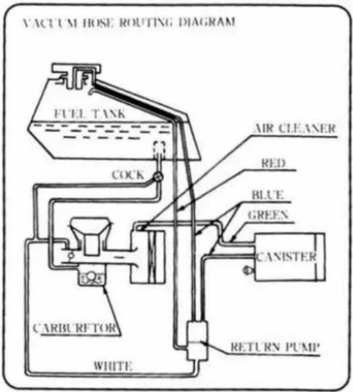

TIRE AND LOAD DATA
The stability and handling characteristics of this motorcycle could become unsafe by the use of improper tire inflation pressures, overworn tires, unsuitable replacement tires, or overloading. When tire tread wears down to the limit replace the tire with only the standard tire. Maintain the inflation pressure specified.
| Air Pressure (Cold) | Size | Make Type | Minimum Tread Depth | ||
| Front | 150 kPa | 90/90-2154S | DUNLOPK750 | 2 mm (0.08 in) | |
| Rear | Up to 97.5 kg Load(215 lbs) | 1.5 kg/cm^2 (21 psi) | 130/80-1765S | DUNLOPK750 | 2 mm (0.08 in) |
| 97.5 ~ 182 kg Load(215 ~ 401 lbs) | 2.0 kg/cm^2 (28 psi) | ||||

IMPORTANT DRIVE CHAIN INFORMATION
To prevent an accident and/or damage to the motorcycle, the drive chain must be properly maintained. It should be lubricated every 600 km (400 mi) and adjusted as often as necessary to keep chain slack at about 50\~60 mm (2.0 \~ 2.4 in) measured midway between sprockets on the lower chain run with the motorcycle on the side stand.
The standard chain is an Enuma EK520SR-O _2 with estimated service life of 10000\~40000 km (6,200 \~ 25,000 mi), depending on the severity of use and the frequency of lubrication and adjustment. For safety, replace the chain with only the standard chain any time it wears to over 323mm (12.7 in), measured over a 20-link portion pulled straight with 10 kg of tension. See the Owner's Manual for chain information.
⑥
ENGINE OIL AND OIL FILTER
| Engine Oil Change -- when filter is not removed: 2.2 liters (2.3 US qt)when filter is removed: 2.5 liters (2.6 US qt) | |
| Engine Oil Type : | API SE,SF or SG |
| : | API SH, SJ or SL with JASO MASAE 10W-40 |
See Owner's Manual for engine oil / filter information and change intervals.
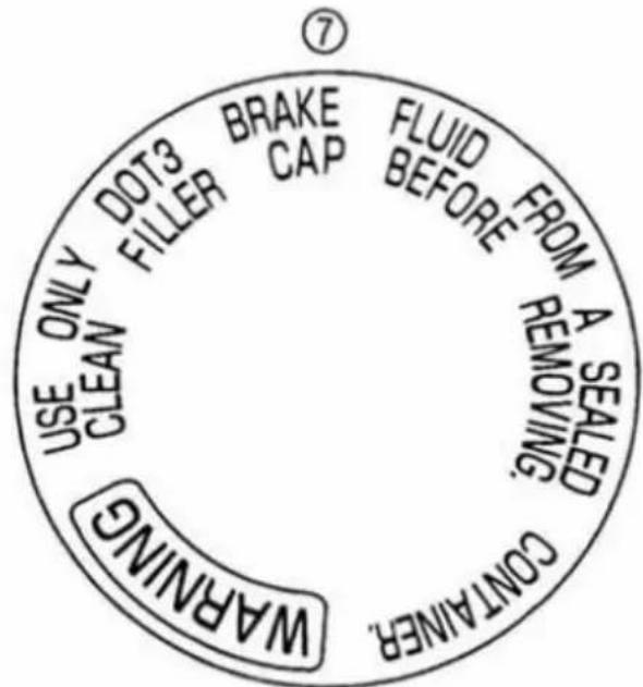
⑧
| MOTORCYCLE NOISE EMISSION CONTROL INF.THISXXXXMOTORCYCLE MEETS EPA NOISE EMISSIONREQUIREMENTS BY THE FEDERAL TEST PROCEDURE.MODIFICATIONS WHICH CAUSE THIS MOTORCYCLE TOEXCEED FEDERAL NOISE STANDARDS ARE PROHIBITEDBY FEDERAL LAW. SEE OWNER'S MANUAL. (KL650A)MODEL SPECIFIC CODE:KAWVIN: JKAKLEA1NOISE LIMIT/CLOSING RPM |
⑨

⑪
BREAK-IN CAUTION
To ensure proper vehicle performance, do not exceed the break-in limits shown on this tachometer.
0-500 mile ) 4,000 rpm 0-800 km
500-1,000 mile ] 6,000 rpm 800-1,600 km
10
USE ONLY DOT3 OR 4 BRAKE FLUID FROM A SEALED CONTAINER. CLEAN FILLER CAP BEFORE REMOVING.
WARNING
UTILISER DU LIOUIDE DE FREIN DOT3 OU 4.
12
IMPORTANT BREAK-IN INSTRUCTIONS
To ensure proper vehicle performance, you must follow the recommendation in the owner's manual regarding break-in maintenance at 800 km (500 mi) and break-in operation up to 1,600 km (1,000 mi).

only on California model
CAUTION
Never fill tank so fuel level rises into filler neck. If tank is overfilled, heat may cause fuel to expand and flow into Evaporative Emission Control System resulting in hard starting and engine hesitation.

WARNING
Rear Carrier Maximum Load Capacity 10 Kg (22 lbs.)
- Never exceed the rear carrier load limit of 10 kg (22 lbs.). It is designed for light items, and overloading can affect handling due to changes in weight distribution and aerodynamic forces.
- Do not exceed the vehicle speed of 130 km/h (80 mph) when carrying a load of more than 5 kg (11 lbs.) on the carrier.
- Never exceed the total vehicle capacity load limit as shown in the Owner's Manual and Tire Information Label.
- Overloading and failure to adjust speed to compensate for addition of cargo may result in loss of control and an accident. Speed must also be adjusted to suit various road and weather conditions.
▲ DANGER/POISON
SHIELD EYES EXPLOSIVE GASES CAN CAUSE BLINDNESS OR INJURY

NO · SPARKS · FLAMES · SMOKING
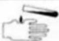
SULFURIC ACID CAN CAUSE BLINDNESS OR SEVERE BURNS
FLUSH EYES IMMEDIATELY WITH WATER
GET MEDICAL HELP FAST
KEE OUT OF THE REACH OF CHILDREN.



IN U.S.A., DISTR. BY KAWASAKI MOTORS CORP. SANTA ANA, CA. 92799-5252

RECYCLE
KL650A


Kawasaki
KAWASAKI HEAVY INDUSTRIES.LTD.
Consumer Products & Machinery Company
Part No. 99987-1406
Printed in Thailand
- Kawasaki
- Includes:
- KLR650
- Motorcycle
- OWNER'S MANUAL
- Quick Reference Guide
- WARNING
- CAUTION
- NOTE
- NOTICE
- FOREWORD
- TABLE OF CONTENTS
- Maintenance and Adjustment....54
- SPECIFICATIONS
- ELECTRICAL EQUIPMENT
- SERIAL NUMBER LOCATIONS
- LOCATION OF PARTS
- 》《《《《《《《《《《《《《《《《《《《《《《《《《《《《 》《《《《《 LOCATION OF LABELS «《《《《《《
- LOADING INFORMATION
- Maximum Load
- GENERAL INFORMATION
- Meter Instruments
- Speedometer and Tachometer
- Coolant Temperature Gauge
- Indicator Lights
- Key
- Ignition Switch/Steering Lock
- To lock the steering:
- Right Handlebar Switches Engine Stop Switch
- Starter Button
- Left Handlebar Switches Dimmer Switch
- Turn Signal Switch
- Horn Button
- Fuel Tank Cap
- Fuel Tank
- ▲WARNING
- Fuel Requirements:
- Fuels Containing Oxygenates
- Fuel Tap
- Side Stand
- Helmet Hook
- Tool Kit Container
- Tool Kit
- Rear Carrier
- 》》》》》》》》》》》》》》》》》》》》》》》》》》》》》》》》》》》》》》》》》》》》》》》》》》》》》》》》》》》》》》》》》》》》》》》》》》》》》》》》》》》》》》》》》》》》》》》》》》》》》,BREAK-IN 《《《《《《《《《《《《《《《《《《《《《《《《《《《《《《《《《《《《《《
- 》《》《》《》《》《》《》《》《》《》《》《》《》《》《》《》《》《》《》《》《》《》《》《》《》《》《》《》《》《》《》《》《》《》《》《》《》《》《》《》《》《》《》《》《》《》《》《》《》《》《》
- Starting the Engine
- Jump Starting
- Connecting Jumper Cables
- Moving Off
- Shifting Gears
- Braking
- Stopping the Engine
- Stopping the Motorcycle in an Emergency
- Parking
- »»»»»»»»»»»»»»»»»»»»»»»»»»»»»»»»»»»»»»»»»»»»»»»»»»»»»»»»»»»»»»»»»»»»»»»»»»»»»»»»»»»»»»»»»»»»»»»»»»»»>
- Safe Riding Technique
- Daily Safety Checks
- Additional Considerations for Off Road Operation
- MAINTENANCE AND ADJUSTMENT
- EMISSION CONTROL INFORMATION
- Crankcase Emission Control System
- Exhaust Emission Control System
- Evaporative Emission Control System
- High Altitude Performance Adjustment Information
- MAINTENANCE AND WARRANTY
- TAMPERING WITH NOISE CONTROL SYSTEM PROHIBITED:
- : Service more frequently when operating in severe conditions: dusty, wet, muddy, high speed, or frequent starting/stopping.
- Engine Oil
- Oil Level Inspection
- Tightening Torque
- Recommended Engine Oil
- Engine Oil Capacity
- Cooling System
- Radiator and Cooling Fan:
- Radiator Hoses:
- Coolant:
- Information for Coolant
- Coolant Level Inspection
- Coolant Change
- Spark Plug
- Maintenance
- Valve Clearance
- Balancer Chain
- Chain Tensioner Adjustment
- Evaporative Emission Control System (California model only)
- Inspection
- Air Cleaner
- Element Removal
- Element Cleaning
- Oil Draining
- Throttle Grip
- Adjustment
- Choke Lever
- Carburetor
- Clutch
- Spark Arrester
- Drive Chain
- Chain Slack Inspection
- Chain Slack Adjustment
- Wear Inspection
- Lubrication
- Brakes
- Brake Wear Inspection
- Disc Brake Fluid:
- Fluid Requirement
- Fluid Level Inspection
- Fluid Change
- Front and Rear Brakes:
- Brake Light Switches
- Front Fork
- Air Pressure:
- Rear Shock Absorber
- Spring Preload Adjustment
- Rebound Damping Force Adjustment
- Wheels
- Tires:
- Tire Wear, Damage
- Minimum Tread Depth
- Battery
- Battery Electrolyte Level Inspection
- Battery Charging
- Battery Removal
- Battery Installation
- Headlight Beam
- Horizontal Adjustment
- Vertical Adjustment
- Fuses
- Fuel System
- General Lubrication
- Apply motor oil to the following pivots:
- Lubricate the following cables with a pressure cable luber:
- Apply grease to the following points:
- Cleaning Your Motorcycle
- Washing your motorcycle
- Painted Surfaces
- Windshield and Other Plastic Parts
- Chrome and Aluminum
- Washing
- Drying
- Protecting
- Bolt and Nut Tightening
- 》》》》》》》》》》》》》》》》》》》》》》》》》》》》》》》》》》》》》》》STORAGE《《《《《《《《《《《《《《《《《《《《《《《《《《《《《《
- Preparation for Storage:
- Preparation for after Storage:
- 》TROUBLESHOOTING GUIDE
- Engine Does Not Start:
- Engine Stalls:
- REPORTING SAFETY DEFECTS
- (For Products Sold in the Continental United States of America Only)
- 》〉〉〉〉〉〉〉〉〉〉〉〉〉〉〉〉〉〉〉〉〉〉〉〉〉〉〉〉〉〉〉〉〉〉〉〉〉〉〉〉〉〉〉〉〉〉〉〉〉〉〉〉〉〉〉〉〉〉〉〉〉〉〉〉〉〉〉〉〉〉〉〉〉〉〉〉〉〉〉〉〉〉〉〉〉〉〉〉〉〉〉〉〉〉〉〉〉〉〉〉>
- ENVIRONMENTAL PROTECTION
- MAINTENANCE RECORD
- VEHICLE EMISSION CONTROL INFORMATION
- TIRE AND LOAD DATA
- IMPORTANT DRIVE CHAIN INFORMATION
- BREAK-IN CAUTION
- IMPORTANT BREAK-IN INSTRUCTIONS
- ▲ DANGER/POISON
- KL650A
Marque : KAWASAKI
Modèle : KLR650
Catégorie : Moto