
SA160FM - Guitare IBANEZ - Notice d'utilisation et mode d'emploi gratuit
Retrouvez gratuitement la notice de l'appareil SA160FM IBANEZ au format PDF.


| Type de produit | Guitare électrique |
| Marque | Ibanez |
| Modèle | SA160FM |
| Corps | Acajou avec table en érable flammé |
| Manche | Érable, vissé |
| Touche | Palissandre, 22 frettes |
| Diapason | 648 mm (25,5 pouces) |
| Micros | 2 micros à simple bobinage Ibanez Infinity (manche et milieu), 1 humbucker Ibanez Infinity (chevalet) |
| Contrôles | 1 volume, 1 tonalité, sélecteur 5 positions |
| Chevalet | Tremolo Ibanez standard (type synchronisé) |
| Mécaniques | Ibanez moulées sous pression |
| Couleur | Transparente (selon finition) |
| Dimensions | Environ 100 cm de long, 33 cm de large, 5 cm d'épaisseur |
| Poids | Environ 3,5 kg |
| Alimentation | Aucune (instrument passif) |
| Accessoires inclus | Clé de réglage du chevalet |
| Entretien et nettoyage | Nettoyer avec un chiffon doux sec après chaque utilisation. Utiliser un produit d'entretien pour guitare pour les cordes et la touche. |
| Sécurité | Éviter les chocs et l'exposition prolongée au soleil ou à l'humidité. |
| Pièces détachées et réparabilité | Pièces disponibles auprès des revendeurs Ibanez agréés. Réparation par un luthier recommandée. |
| Informations générales | Guitare polyvalente adaptée à de nombreux styles (rock, blues, pop). |
FOIRE AUX QUESTIONS - SA160FM IBANEZ
Questions des utilisateurs sur SA160FM IBANEZ
0 question sur cet appareil. Repondez a celles que vous connaissez ou posez la votre.
Poser une nouvelle question sur cet appareil
Téléchargez la notice de votre Guitare au format PDF gratuitement ! Retrouvez votre notice SA160FM - IBANEZ et reprennez votre appareil électronique en main. Sur cette page sont publiés tous les documents nécessaires à l'utilisation de votre appareil SA160FM de la marque IBANEZ.
MODE D'EMPLOI SA160FM IBANEZ
Maintenance >>
Our congratulations and deepest thanks on making Ibanez your choice of instrument. Ibanez standards are second to none. All Ibanez Instruments are set up to our strict quality control standards before shipping. The purpose of this manual is to explain how to maintain your Instrument's finish and to keep your guitar playing as well as it did when it left our factory.
CLEANING
Regular cleaning of your guitar is one the most important ways you can maintain the finish and lengthen string life. After playing, wipe down your instrument to remove any perspiration from the
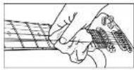
instrument. Perspiration can actually contain acids that can be corrosive to the strings and metal parts of the guitar. Gloss finish guitars should be polished with polish formulated specifically for musical instruments, and a soft, treated guitar cloth or a cotton rag. Abrasive rags such as polyester can scratch the finish. Oil finished guitars should be wiped clean immediately after playing with a dry cotton rag only. If your guitar has become discolored due to extended use or heavy perspiration, factory appearance, see a qualified guitar repair person about methods to restore the oil finish to its original factory appearance.
STRINGS AND TUNING MACHINES
If strings become dirty, discolored, or produce a dull sound or buzz, replace the strings with new ones. For best results we recommend replacing one string at a time, this will help to avoid removing the string tension from the neck. When replacing strings with different gauge strings, it may be necessary to adjust the truss rail tension. (We recommend only qualified technicians perform this.) Instruments that have tremolo systems installed may need to be adjusted after string replacement as changes in string tension can cause the tremolo to raise or lower, flangez guitars and basses are factory equipped with the following string gauges. Please follow the instructions below for your particular model. The strings should be lightly wound on the 2-to-3 inch machines from top to bottom with 2 to 3 string swaps around the post. In the case of unwound guitar strings, the ends of the strings should be prepared as shown in the diagram to prevent unintentional slippage from the posts. In the case of tuning machines, where the string ends are inserted into the posts, the string can be cut to length in advance using a pair of string cutters.
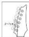
If the tuning machines are sealed gear units, they are self-lubricating types. The set screws for the tuning knob are adjustment screws that can be tightened with a small Phillips head screwdriver to increase the tension.

The following step may be being bound and set as long since the last hand of the way, but being bound to be bound at the bottom. The step is not closed by the end of the step.

| Solid pulters w/Tremos, JTB, ICB, MAX & ALL Go | 0.06/01 1/016,004/035/249 inch |
| DCSP1MH, SZ, AOS, NZ, AOC, ANK & NC | 0.06/01 3/017,004/035/248 inch |
| 7-String model | 0.06/01 3/017,004/035/246/054 inch |
| MIMEI | 0.04/01 7/030,040/035/274 inch |
NECK
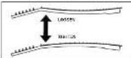
Ibanez steel string models are equipped with adjustable truss rods. The purpose of a truss rod is to adjust the neck to counteract string tension. There are many measures for truss rod adjustments. One of the most frequent reasons is changing string gauges or tuning pitch which can affect string tension. String tension changes may affect the string height and cause fret buzz or notes that don't ring true. To adjust the truss rod, locate the truss rod nut and adjust it by inserting the correct wrench into the nut and tightening clockwise or loosening (counter clockwise) the rod. Truss rod tension can be measured by installing a capo at the first front the holding the strings down at the first position where the neck joins the body. Insert a thickness gauge between the string and the frct at the 8th frct. There should
between 0.3 mm to 0.5mm clearance. That clearance is referred to as "neck relief." Too much neck relief can cause the neck to have higher action in the middle of the neck causing poor intonation and uncomfortable playability. No neck relief can cause fret buzz.
"Supervise you just to check any adjusting the neck and we recommend only, according to our form of a exercise."


ACTION
Ibanze guitar and bass string action is set at the factory. However there are many reasons that an instrument's string height can change. Instruments can be affected by changes in temperature and moisture. High string action can make the guitar to play a very fine, but if the difficult to play a very fine, it is not just one or more. The first buzz or unclear notes can occur. To remedy this, follow the instructions for the particular type of bridge installed. In the case of string action, make sure the guitar is in tune and the truss rod is adjusted properly. Ibanze action is set at the 14th fret. The action may also need to be readjusted with the second letter when an adjusted or strings have been changed to a different gauge. Follow the instructions in the relevant bridge manual to make adjustments.
If coming one, then these described above are used, gradually increases the action clearance from the tristile side through in the junction.
.009 string's puirars except Glo lionea 1.5mm 2.0mm all Glo lionea & 0.10...0.14 string's puirars 1.7mm 2.3mm
INTONATION
Intonation adjustment is the operation of adjusting the location of the string at the saddle to compensate for different string gauges or different tunings. Follow the instructions
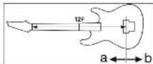
of the particular bridge intonation below. Intonation is properly set when the 12th fret note and the 12th fret harmonic are exactly the same note. This is the center point of the scale and the most accurate way of setting a standard scale length. With the harmonic note as the standard, if the fretted note is flat move the bridge saddle forward toward the headstock (a) to decrease the string length. If the fretted note is sharp, move it back away from the headstock (b) to increase the string length intonation adjustments.
Please note that things can be done with the next 2 weeks, so a way can't be things done.
PICKUPS
The output level of the instrument as well as the quality of the signal can be affected by the pickup height. Pickup height should be adjusted until the volume of neck and bridge pickups are almost equal with both

volumes wide open. The volume may drop drastically if the pickup height is too low. As the pickups are magnetic, fret buzzing and distortion may occur if the pickup is too close to the strings. Use a small screwdriver to make adjustments to raise or lower the pickup.
The following table is provided in the image:
Guitar Bridges >>
GIBRALTAR CUSTOM BRIDGE
The height adjustment can be adjusted by 4 pcs of 2.0mm of allen screws (B) on the bridge. Since the adjustment screws are locked by the bridge lock screw (A), you must loosen the bridge lock screw by 3.0mm Allen wrench before adjustment.
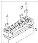
Each saddle is also locked by a saddle lock screw (C). To adjust the intonation, use a 2.0mm Allen wrench to loosen the saddle locke screws, and then adjust the Intonation screw (D) by a 2.0mm Allen wrench. When you are finished saddle and tune the guitar.
GIBRALTAR III & FULL TUNE III

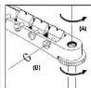
The action can be adjusted by using a slot head (-) screwdriver to turn the adjustment bolt at either end (A). The intonation can be adjusted by moving the saddle forward or backward using a screwdriver to turn the adjustment screw of each saddle (B).
HARDTAIL BRIDGE
To change strings, thread the new strings through the string grommet located on the back of the guitar and bring them up and over the saddle. The intonation can be adjusted by adjusting the saddle forward or backward using a Phillips (+) head screwdriver on the intonation

raising or lowering the small Allen screws using a wrench on either side of the saddle.
QUIK CHANGE TAILPIECES
The height adjustment of the QUIK CHANGE III can be adjusted by using a slot head (-) screwdriver or a coin turn the adjustment studs at either side of the tallpiece (C).


QUIK CHANGE ULTRA / FINE TUNING FUNCTION QUIK CHANGE ULTRA has FINE TUNER function. Even after by the tuning machine you can make a quick-fire adjustment by FINE TUNERS (E

DOWNSHIFTER
INSTALLING THE STRING To install a new string insert the ball end of the new string into the slot and place the ball end into the internal hook area of the saddle as shown. Pull the string tight to the saddle and restring the rest of the string as you normally would on the machine head.
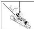
SPECIAL TUNING The Downshifter also allows the pitch to be raised by setting the standard tuning while the lever is in the lower position. When the lever is raised the pitch will also be raised and can be adjusted to the desired pitch.
The Ibanez DOWNSHIFTER allows the pitch of a string to be dropped to a preset desired position with a simple lever operation. To achieve precise tuning for both the up and down positions, you will need to preset both lever settings before operating the Downshifter.
First check that the Downshifter lever arm is raised to the up position then tune the string normally using the standard tuning machines on the headstock. (Note: the Downshifter tuning screw has no effect on the pitch in the up position.) Next, lower the lever on the Downshifter to the down the string will drop down. Adjust the rear

tuning screw clockwise to reduce the pitch, or counter clockwise to raise the pitch. This adjustment can be done by hand or with a standard screwdriver or a coin until the desired down pitch is acquired. (The preset factory pitch is set one whole step down to D.) When the lever is raised to the up position, the thumbscrew can be turned freely but will have no effect on the raised le affect the settings of down lever pitch.

PLEASE NOTE: The Downshifter device was designed to provide the highest level of pitch accuracy. However, it should be understood that the Downshifter is a mechanical device. Pitch variations and tuning readjustments, especially after frequent use, are to be expected.
Guitar Electronics >>
SWITCHING FUNCTION
Ibanez instruments are unique in the simplicity and versatility of our switching systems. Each model was designed to allow the maximum amount of useful pickup positions with the simplest operations.
SPLITS FUNCTION
WITH "TRUE-DUO" SYSTEM
*BRIDGE PICKUP : "TRUE-DUO BUCKER"
![graph TD A["SAS32 1.2 PDKUP(SH-H)"] --> B["MEM CENTER-RANGE"] B --> C["VOLUME POT"] C --> D["MEM CENTER-RANGE"] D --> E["VOLUME POT"] E --> F["MEM CENTER-RANGE"] F --> G["VOLUME POT"] G --> H["MEM CENTER-RANGE"] H --> I["VOLUME POT"] I --> J["MEM CENTER-RANGE"] J --> K["VOLUME POT"] K --> L["MEM CEN…](/content/2026/06/1272330/images/bc9888ad653c2b9d2c8d712004e4b66ae3a6259dd242a4c076a8c5e83576404e.jpg)
![graph TD A["SASIK/SA260 3 PICKUPHS-S-10"] --> B["RENDUCTOR PIPUP MODE"] B --> C["VOLUME POT SATCH FOR PIPUP"] C --> D["DATA Collection"] D --> E["DATA INPUT"] E --> F["DATA OUTPUT"] F --> G["DATA Collection"] G --> H["DATA INPUT"] H --> I["DATA OUTPUT"] I --> J["DATA Collection"] J --> K["DATA INPUT…](/content/2026/06/1272330/images/1cdf314571b9c69c9705fd24ec88d56e71ebd468f0cb3a86060732829a6d9351.jpg)
SPLITS FUNCTION
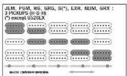

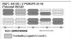
OTHERS
![graph TD A["Microcontroller"] --> B["Microcontroller with GPIO port"] B --> C["Microcontroller with GPIO port"] C --> D["Microcontroller with GPIO port"] D --> E["Microcontroller with GPIO port"] E --> F["Microcontroller with GPIO port"] F --> G["Microcontroller with GPIO port"] G --> H["Microcontro…](/content/2026/06/1272330/images/4ee6a1a17e47a7a91e92f67968ffdc10a6745b5695fc515681c6258676def755.jpg)
SZ:2 PICKUPS (H-H)


MMM, RG120, S520EX, GSA, GRX, GAX30 : 2 PICKUPS (H-H)

Guitar Controls >>
CONTROLS
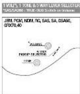

1 NO. 1 ONE & SANY TIGGLE SWITCH





Ibanez
the use is valid that the above-enclosed equipments may conform to protection requirements of the Information 50 mill instructions. DIRECTORS, ASSOCIATED Electromagnetic consulted by CE
Tremolos >>
EDGE PRO II TREMOLO
TREMOLO ARM INSTALLATION
The tremolo arm can be inserted and removed very easily. Insert the arm into the armhole on the tremolo base plate. Pull up on the arm to remove it.

ARM ROTATION TORQUE
The rotation torque of the arm can be adjusted by raising the tremolo and inserting a 2.0mm Allen wrench in the screw (A) on the tremolo block, Turning this screw clockwise will tighten the arm torque and turning the screw counter clockwise will loosen the arm torque.
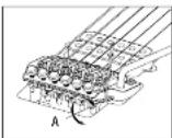
ARM ACTION
The tremolo arm action can be adjusted by using a 2.0mm Allen wrench on the screw (B) of the tremolo block.

FINE TUNING
Even after locking the locking nut, you can use the fine tuners to make fine adjustments to the tuning of each string. You should adjust all of the fine tuners (C) to the center of their adjustable range before you lock the locking nut.

ADJUSTING THE ACTION
To adjust the entire tremolo unit up or down, use an Allen wrench to turn the stud bolt (E) located at the left and right of the tremolo unit. (This cannot be adjusted for each individual string.)
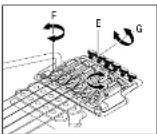
ADJUSTING THE INTONATION
Before you adjust the intonation, use a 3 mm Allen wrench to loosen the pressure pad screws (G) of the locking nut so that the strings are released. Use a 2 mm Allen wrench to loosen the saddle lock screws (F) of each saddle, and move the saddle. Firmly tighten the saddle lock screws, tune the guitar, and then check the intonation. Repeat these adjustments until the intonation is correct, and then tighten the pressure pad screws of the locking nut.
You may install each saddle lock screw in either the forward or rear position, depending on the position of the saddle. The unit is designed so that the fine tuning screw will not operate if the position of the saddle extends beyond the front edge of the base plate. Note: When loosening the saddle lock screws, you must loosen the strings sufficiently before making adjustments.
REPLACING THE STRINGS
The EDGE-PRO II tremolo will accommodate either strings from which the ball and has been cut, or conventional strings from which the ball end has not been cut. To remove a string, use a 3 mm Allen wrench to loosen the pressure pad screw of the locking nut (Fig.1), remove the string from the tuning machine, and use a 3 mm Allen wrench to loosen the string stepper motor. Then, it is also that this counter-clockwise will automatically retract the holder block, so loosen the string stopper screw all the way until the holder block stops retracting. Remove the old string, insert approximately 3 cm of the new string with ball end into the saddle, and while making sure that the string is positioned in the center of the saddle, tighten the string stopper screw (Fig.2). Turning this clockwise will automatically advance the holder block, so after making sure that the string is firmly fastened, wind the string around the tuning machine, and then we can be kept down. The pressor of the locking nut
When installing a wound string from which the ball end has been cut off, you can leave the overwound portion of the winding intact In order to prevent the winding from loosening. Insert approximately 1–3 cm of the tip into the saddle, and install the string in the same way as a conventional string from which the ball end has not been cut off. Since the attachment angle of the tremolo will change significantly if all strings are removed at once, you should replace the strings one at a time. On the bottom of each saddle there is a guide stopper that indicates the length of string to be inserted. The appropriate length will be inserted if you insert the string until the tip contacts this guide. If a string breaks at the saddle, it may fall into the tremolo cavity when you need to keep the spring stopper on the broken string either by attaching the tremolo swing cavity cover plate from the back of the guitar, or from the opening in the cover plate. If the broken spring remains in the saddle, remove it from above.
Note: Before you tune a string, make sure that the string slopper screw is firmly tightened. Note: To prevent the string slopper screw from falling out, do not loosen it more than three turns after the holder block has stopped retracting.
TREMOLO SPRINGS
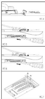
The EDGE-PRO II tremolo is designed to function optimally when it is installed approximately parallel with the surface of the guitar body (Fig.4). The angle at the center is 1/2 and the angle is adjusted by changing the length of the tremolo springs inside the tremola spring cavity in the back of the guitar body. Working through the adjustment holes in the tremolo spring cavity cover plate, use a Philips (+) screwdriver to turn the tremola spring body. The angle is adjusted the length of the tremolo springs. If the tremolo is tilted forward toward the neck of the guitar (Fig.5), turn the screws clockwise to tighten the springs. Conversely, if the tremolo is tilted backward away from the neck (Fig.6), turn the screws counter-clockwise to improve the position of the tremolo spring. It is accurately, re-check the angle of the tremolo, and repeat the adjustment until the tremolo angle is correct. The EDGE-PRO II tremolo is designed to function optimally when three springs are
set of strings installed. If you replace the strings with a different gauge set, you can adjust the tremolo angle by changing the number of springs or the way in which the springs are installed. Leosen all strings before you add or remove a tremolo spring. The EDGE-PRO II tremolo uses a block lock mechanism to fasten the tremolo springs to the block. Before you change the number of springs of the way in which they are installed, use a Philips (+) screwdriver to remove the block lock (Fig.7).
NOTE: If you want to install four or five tremolo springs, insert the springs into the block nut attachment screw holes. (In this case, it will not be possible to attach the block nut.)

ZR (ZERO RESISTANCE) TREMOLO
TREMOLO ARM
Loosen the screw cap, insert the arm into the tremolo unit, and rotate it to fasten it in place (Fig.8). Rotate the arm to adjust it to the desired height. The arm torque is adjusted by the tightness of the screw cap. To remove the arm, loosen the screw cap and rotate the arm counterclockwise (Fig.9).


FINE TUNING
Even after locking the locking nut, you can use the fine tuners (Fig.10 A) to make fine adjustments to the tuning of each string. You should adjust all of the fine tuners to the center of their adjustable range before you lock the locking nut.

ADJUSTING THE ACTION
To adjust the entire tremolo unit up or down, use an Allen wrench to turn the stud bolt (Fig.10 B) located at the left and right of the tremolo unit. (This cannot be adjusted for each individual string.)
ADJUSTING THE INTONATION Loosen the string stopper bolt of the locking nut (Fig. 11). Remove the intonation adjustment bolt (Fig. 12 B) from within the bridge unit, fasten it into the screw hole in the rear of the saddle, and tighten it so that the tip of the bolt contacts the boss of the bridge unit. Loosen the saddle lock bolt (Fig. 10 C), and turn the intonation adjustment bolt to adjust the position of the saddle. After completing the adjustment, tighten the saddle lock bolt sufficiently to prevent the saddle from moving forward during tuning, and store the intonation adjustment bolt inside the bridge unit.
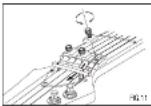
REPLACING THE STRINGS Loosen the string stopper bolt of the locking nut (Fig.11), completely loosen the string at the tuning machine, use an Allen wrench to loosen the string stopper bolt of the bridge saddle (Fig.12 A), and remove the old string. Use wire cutters to remove the ball end from the new string as shown in Figure 13, Insert this end of the string into the bridge saddle, fasten it firmly, and then tighten the string at the tuning machine. After tuning, check the angle of the tremolo unit, and fasten the string stopper bolt of the locking nut to finish the procedure.


ADJUSTING THE ZERO POINT SYSTEM
The Zero Point system makes it easier to tune a floating tremolo unit, provides greater tuning stability after amming, and limits the tuning drift that would otherwise occur when a string breaks. "If the Zero Point system is not adjusted to the correct position it will not function optimally, since it will either be completely floating, or the Zero Point system and the string tension will be in balance. You must perform this adjustment accurately.


with the guitar turned correctly, adjust the Main Spring make sure that the Stop Roll makes contact with the Tramolo Block and Stopper.

with the guffer hinned correctly, Stop Red must make contact with the Tremlin Black and Stopper. If it is adjusted correctly, the tameron white pulling down on the arm will be slightly less than tension white pulling up. The balance of frame is about 3.7 (With this setup, stop red must the tremlin black and stopper are for the right to produce improved
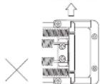
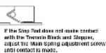
Again, if the Step Find does not make contact with the Transicle Block and Snupper, adjust the Main Spring adjustment screwwarp contact is made.
(Note 2) When a string breaks, because of the tension of neck, the tuning of other strings will be a little higher but well limits within acceptable range.
SWITCHING TO FLOATING OPERATION
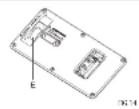
By stopping the Zero Point system from functioning, you can make the tremolo float completely. While holding the arm up, remove the stop rod and sub spring. With the guitar tuned correctly, use the main spring adjustment knob (Fig. 14E) to adjust the angle of the tremolo unit. If the tremolo unit is tilted forward toward the neck, turn the spring adjustment knob in the plus (+) direction.
Conversely, if the tremolo unit is tilted backward away from the neck, turn the spring adjustment knob in the minus (-) direction.
*You will need to tune repeatedly during the process of adjusting the tremolo angle in the floating state, since the tuning will drift each time you adjust the main spring adjustment knob.

EDGE III TREMOLO
TREMOLO ARM INSTALLATION
The tremolo arm can be inserted and removed very easily. Insert the arm into the armhole on the tremolo base plate. Pull up on the arm to remove it.
ARM ROTATION TORQUE
The rotation torque of the arm can be adjusted by raising the tremolo and inserting a 1.5mm Allen wrench in the screw (A) on the tremolo block, turning this screw clockwise will tighten the arm torque and turning the screw counter clockwise will loosen the arm torque.
ARM ACTION
The tremolo arm action can be adjusted by using a 3.0mm Allen wrench on the screw (B) of the tremolo screw.
FINE TUNING
Even after locking the locking nut, you can use the fine tuners to make fine adjustments to the tuning of each string. You should adjust all of the fine tuners (C) to the center of adjustable range before you lock the locking nut.
ADJUSTING THE ACTION
To adjust the entire tremolo unit up or down, use an Allen wrench to turn the stud bolt (E) located at the left and right of the tremolo unit. (This cannot be adjusted for each individual string.)
ADJUSTING THE INTONATION
Loosen the Pressure pad screw (D) on the locking nut and loosen the string to be adjusted. Loosen the Saddle lock screws (F) on the saddle to be adjusted and adjust the saddle forward or backward. Tighten the Saddle lock screw (F) and tune the string. After rechecking the intonation, tighten the Pressure pad screw (D).
*For the following lines we have been here next to a table of contents. These lines are in comparison paper, with allowing the current mobile environment. If the station was not located there, the table was to be next further, remove the information area and insert into the lock located further back on the bridge plate.
REPLACING THE STRINGS
In the case of EDGE III tremolo, replace the strings one by one. Removing all the old strings at once will release the tension on the tremolo and change the tremolo angle "up-pull." Loosen the Pressure pad screw (D) on the locking nut and loosen the string to be replaced. Loosen the String stopper screw (G) and remove the string from the saddle. Cut off the ball end of new string as shown on the illustration and insert the between the saddle and the String holder block, stopper screw (G) and tune the string. After check tighten the Pressure pad screw (D) on the lockin
EDGE II
ADJUSTING THE TREMOLO SPRING The tremolo springs adjust the tremolo angle by tightening or loosening the tremolo tension. To adjust tremolo angle, locate the adjustment screws in the rear tremolo cavity. The tremolo system when in tune should sit parallel to the surface of the guitar as follows.
If the tremolo system is not sitting parallel to the surface of the guitar, remove the tremolo cavity cover plate and tighten the Tremolo tension adjustment screws if the tremolo is forward dumped. Loosen the screws

if the tremolo is up-pulled. Return the strings to the proper pitch and check the angle. Choose the number and placement of the tremolo springs according to the string gauge and the tremolo angle.
ILT LOCKING TREMOLO
TREMOLO ARM
Insert the tremolo arm into the arm socket and tighten the fingertip tension adjustment wheel. The rotation torque of the arm can be lightened or loosened by adjusting the tremolo arm nut located at the base of the tremolo arm.

FINE TUNING
After locking the top lock, fine tuning the instrument can be done by turning the fine tuning screws (A).
* To allow most man to be using adjustment, I recommend that the line hues be act to the middle position before kolding the net.
ADJUSTING THE STRING HEIGHT
The height adjustment of the tremolo can be raised or lowered by adjusting the pivot studs (8) that the tremolo mounts on. These are located at either side of the front of the bridge. Clockwise lowers the tremolo and counter clockwise raises the tremolo.

ADJUSTING THE INTONATION
Loosen the Pressure pad screw (C) on the locking nut and loosen the string to be adjusted. Loosen the Saddle lock screws (D) on the saddle to be adjusted and adjust the saddle forward or backward. Tighten the Saddle lock screw (D) and tune the string. After rechecking the intonation, tighten the Pressure pad screw (C).

* On the book, the book are hard to find such a dark scene. These plans be used in charge of proper art and use the maximum amount of interest. If this is used, it is applied because it is additional to do not reach latitude. However, the boundary scene is easily free. It is the first location rather than the bridge area.
REPLACING THE STRINGS
In the case of Lu-TRS III tremolo, replace the strings one by one. Removing all the old strings at once will release the tension on the tremolo and change the tremolo angle "up-pull." Loosen the Pressure pad screw (C) on the locking nut and loosen the string to be replaced. Loosen the String stopper screw (E) and remove the string from the saddle. Cut off the ball end of new string as shown on the illust side of new string between the saddle and the S Tighten the String stopper screw (E) and tune the intonation, tighten the Pressure pad screw (F).

ILT
ADJUSTING THE TREMOLO SPRIN The tremolo springs adjust the tremolo angle by tightening or loosening the tremolo tension. To adjust tremolo angle, locate the adjustment screws in the rear tremolo cavity. The tremolo system when in tune should sit parallel to the surface of the guitar as follows if the tremolo system is not sitting

parallel to the surface of the guitar, remove the tremolo cavity cover plate and tighten the Tremolo tension adjustment screws if the tremolo is forward dumped. Loosen the screws if the tremolo is up-pulled.
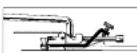
Retune the strings to the proper pitch and check the angle. Choose the number and placement of the tremolo springs according to the string gauge and the tremolo angle.
FAT/SAT TREMOLO
TREMOLO ARM INSTALLATION The tremolo arm can be inserted and removed very easily. Insert the arm into the armhole on the tremolo base plate. Pull up on the arm to remove it.

TREMOLO ARM ADJUSTMENT
(SAT PRO) To adjust the height of the arm, remove the tremolo spring cover from the back of the guitar, and use a 3 mm Allen wrench to turn the height adjustment screw attached to the bottom of the tremolo block. Tightening this in the clockwise direction will raise the height.

ARM ROTATION TORQUE The rotation torque of the arm can be adjusted by raising the tremolo and inserting a 1.5mm Allen wrench in the screw (A) on the tremolo block. Turning this screw clockwise will tighten the arm torque and turning the screw counter clockwise will loosen the arm torque.

ADJUSTING THE STRING HEIGHT (SAT PRO)
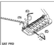
To adjust the action of each string, use a 1.5 mm Allen wrench to turn the screw on the saddle (C). The overall height can be adjusted on either side of the SAT PRO tremolo unit. To adjust the height, use a 3 mm Allen wrench to turn the stud (D) located on either side of the unit. Use caution when

adjusting the height of the entire tremolo unit; adjust both sides to the same height to ensure optimum tremolo operation.
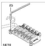
ADJUSTING THE STRING HEIGHT (FAT20/FAT10/SAT10)
The height adjustment of the tremolo can be raised or lowered by adjusting the pivot studs (C) that the tremolo mounts on. These are located at either side of the front of the bridge. Clockwise lowers the tremolo and counter clockwise raises the tremolo.


INTONATION ADJUSTMENT
(SAT PRO) To adjust the inflation, use a 1.5 mm Allen wrench to turn the screw located at the rear of the saddle (E). Turn the screw clockwise to move the saddle toward the rear, or counter-clockwise to move the saddle forward.
INTONATION ADJUSTMENT (FAT20)
To assure that no movement can occur each saddle has a set screw that locks the saddle. When adjusting the intonation, loosen the saddle lock screw using a 2mm Allen wrench. (Q) To adjust the intonation, insert a 2.5mm Allen wrench into the saddle screw at the rear of the tremolo. Turning the wrench clockwise will adjust the saddle backward. Counter clockwise will adjust the saddle forward. After the correct intonation location of the saddle is set tighten the saddle lock down screw to assure no movement will occur. (E)
INTONATION ADJUSTMENT (FAT10/SAT10)
The intonation can be adjusted by adjusting the saddle forward or backward using a Phillips (+) head screwdriver on the intonation adjustment screw at the rear of the bridge.


ADJUSTING THE INTONATION &
THE STRING HEIGHT (FAT 6) The intonation can be adjusted by adjusting the saddle forward or backward using a philips(-) head adjustment screw at the rear of the bridge. String height is controlled by raising or lowering the small allen screws using a wrench on either side of the saddle.

REPLACING THE STRINGS To replace strings, thread the new strings through the string holes located on the back of the guitar. The strings are then threaded through the tremolo block and up and over the saddle.

FAT/SAT (expect FAT6)
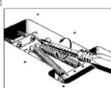
ADJUSTING THE TREMOLO SPRIN A standard tremolo can be adjusted so that the pitch can be raised when the tremolo arm is pulled up to loosen the tremolo springs located under the tremolo cavity on the back of the guitar. One disadvantage of this procedure is that it can cause the pitch to go sharp if string breaks. To remedy this, adjust the tremolo plate so it sits flush on the body by lightening the tremolo springs. Choose the number and placement of the tremolo springs according to the string gauge and the tremolo adjustment.



- MAINTENANCE
- CLEANING
- STRINGS AND TUNING MACHINES
- NECK
- ACTION
- INTONATION
- PICKUPS
- GUITAR BRIDGES
- GIBRALTAR CUSTOM BRIDGE
- GIBRALTAR III & FULL TUNE III
- HARDTAIL BRIDGE
- QUIK CHANGE TAILPIECES
- DOWNSHIFTER
- GUITAR ELECTRONICS
- SWITCHING FUNCTION
- GUITAR CONTROLS
- TREMOLOS
- EDGE PRO II TREMOLO
- ZR (ZERO RESISTANCE) TREMOLO
- EDGE III TREMOLO
- ILT LOCKING TREMOLO
- FAT/SAT TREMOLO
Marque : IBANEZ
Modèle : SA160FM
Catégorie : Guitare