
CNPS10X Optima - Refroidissement informatique ZALMAN - Notice d'utilisation et mode d'emploi gratuit
Retrouvez gratuitement la notice de l'appareil CNPS10X Optima ZALMAN au format PDF.


| Type de produit | Ventilateur de refroidissement CPU |
| Marque | Zalman |
| Modèle | CNPS10X Optima |
| Socket compatibles | Intel LGA 115x/1366/2011/2066, AMD AM2/AM3/AM4/AM5 |
| Dimensions (L x l x H) | 126 x 76 x 159 mm |
| Poids | 550 g |
| Matériaux | Aluminium (ailettes), cuivre (caloducs) |
| Nombre de caloducs | 4 |
| Type de ventilateur | 120 mm avec LED bleue |
| Vitesse de rotation | 800 - 1500 tr/min (PWM) |
| Débit d'air | 36,8 - 70,3 CFM |
| Niveau sonore | 17 - 26 dBA |
| Connecteur | 4 broches PWM |
| Tension d'alimentation | 12 V |
| Consommation électrique | 1,8 W |
| Pression statique | 1,55 mmH2O |
| Durée de vie du ventilateur | 50 000 heures (roulement à huile) |
| Garantie | 2 ans |
| Installation | Kit de montage universel inclus, pâte thermique pré-appliquée |
| Entretien | Dépoussiérage régulier du ventilateur et des ailettes |
FOIRE AUX QUESTIONS - CNPS10X Optima ZALMAN
Questions des utilisateurs sur CNPS10X Optima ZALMAN
0 question sur cet appareil. Repondez a celles que vous connaissez ou posez la votre.
Poser une nouvelle question sur cet appareil
Téléchargez la notice de votre Refroidissement informatique au format PDF gratuitement ! Retrouvez votre notice CNPS10X Optima - ZALMAN et reprennez votre appareil électronique en main. Sur cette page sont publiés tous les documents nécessaires à l'utilisation de votre appareil CNPS10X Optima de la marque ZALMAN.
MODE D'EMPLOI CNPS10X Optima ZALMAN
User's Manual
CNPS10X Optima
Intel Socket 1155/1156/1366/775 CPU
Core i7 Extreme
Core i7
Core i5
Core i3
Core 2 Quad
Core 2 Duo
Core 2 Extreme
Dual Core Pentium
Pentium D
Pentium 4
Celeron
AMD Socket FM1/AM3/AM2+/AM2 CPU
Llano
Phenom II
Phenom
Athlon II X2
Athlon
Athlon 64
Athlon X2
Athlon 64 X2
Athlon FX
Athlon 64 FX
Opteron
Sempron

To ensure safe and easy installation, please read the following precautions
www.ZALMAN.com
1. Precautions
1) This cooler must be used with a 120mm fan.
2) Do not ingest the Thermal Grease, and avoid its contact with skin and eyes. If contact is made with skin, wash off with water. If ingested or irritation persists, seek medical attention.
3) To prevent possible injuries, gloves must be worn while handling this product.
4) Excessive force exerted on the fan may cause damage to the fan and/or system.
5) Use and keep product away from reach of children.
6) Check the components list and condition of the product before installation. If any problem is found, contact the retailer to obtain a replacement.
7) During transportation of the system, the cooler must be removed. Zalman is not responsible for any damages that occur during the transport of a system.
8) Product design and specifications may be revised to improve quality and performance.
Disclaimer) Zalman Tech Co., Ltd. is not responsible for any damages due to external causes, including but not limited to, improper use, problems with electrical power, accident, neglect, alteration, repair, improper installation, or improper testing.
- Specifications
| Model Spec. | CNPS10X Optima | ||
| Material | Pure Copper and Aluminum | ||
| Weight | 630g | ||
| Dimensions | 132(L)×85(W)×152(H)mm | ||
| Fan | Bearing-Type | FSB(Fluid Shield Bearing) | |
| RPM | 1000~1700 rpm±10% | ||
| Noise Level | 17.0~28.0 dBA±10% | ||
| Thermal Grease [ZM-STG2M] | Contents | 1g | |
| Temperature Range | -40°C ~ +150°C (-40 ~ +302°F) | ||
3. Components
1) Common Components
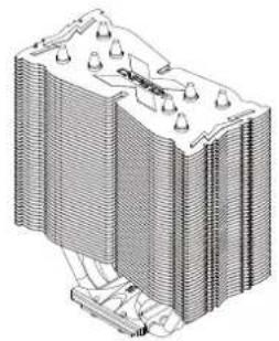
Cooler
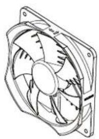
Fan
Manual

Backplate

Fan Fixing Clips
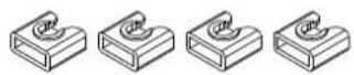
Side Cap

Bolts

Nuts

Loading Block
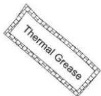
Thermal Grease [ZM-STG2M]

Double-sided Tape
2) Intel Components
Socket 1155/1156/1366/775
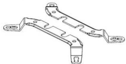
Intel Clip
3) AMD Components
Socket FM1/AM3/AM2+/AM2

AMD Clip A
4. Installation Requirements
1) Space Requirements
The cooler's installation requires an unobstructed space of 137mm(width), 130mm(length), and 155mm(height), with the CPU as a central reference point. Please check if components such as ODDs and PSU protrude into the required space.
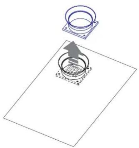
2) Air Guide Removal
Air guides on enclosures must be removed before the cooler's installation since they protrude into the cooler's required space.

3) Cooler Orientation
As shown in the diagram below, it is recommended that the cooler be installed so that air flows from the cooler toward the enclosure's rear exhaust fan to be released.
※ Install the fan so that the ZALMAN logo is oriented in relations to the rear of the case as in the diagram.
※Recommended cooler orientation may differ according to the motherboard model.

4) CPU and RAM interference check (limited to systems with RAM heatsinks)
For Intel and AMD Socket motherboards's with a RAM height of 36mm (1.42") and greater, there will be physical interference with the CPU cooler resulting in the inability to utilize dual and full-channel modes. Please check the height of your RAM modules prior to installation.
5. Installation
1) Intel Socket 1155/1156/775 and Socket 1366 Installation
① Unfasten the Bolts on the Cooler's Base one thread, insert the Intel Clip between the Cover and the Base, and then refasten the Bolts.
![graph TD A["Start"] --> B["Actuator with screwdriver"] B --> C["Step 1: Inserted screwdriver"] C --> D["Step 2: Inserted base cover"] D --> E["Step 3: Inserted base cover"] E --> F["Step 4: Inserted base cover"] F --> G["Step 5: Inserted base cover"] G --> H["Step 6: Inserted base cover"] H --> I["S…](/content/2026/06/1265089/images/eb1b6c04d9743967ffdd7ec6367589a18a91701a4633ce3bddb9d1d5be06ab0b.jpg)
② Install Bolts to the Backplate according to the Socket Type and secure with Side Caps.

Caution
Take note of the orientation of the Nuts and the Side Caps.


③ - a Socket 775 Installation
Remove the Sticker Cover from the Lower Tier of the Loading Block and attach to the Backplate.

Attach Double-sided Tape to the Loading Block and remove the Double-sided Tape Cover.

Caution
Please make note of the orientation of the Loading Block's Installation.

③ - ⓑ Socket 1155 / 1156 / 1366 Installation
Attach Double-sided Tape to the center of the Backplate and remove the Double-sided Tape's Cover.
※ Socket 1155 / 1156 / 1366 Installation does not require the Loading Block.

④ Align the Backplate's Nuts with the motherboard's Clip Support's installation holes and fasten to the motherboard.

⑤ Apply the enclosed Thermal Grease to the CPU's surface and install the Cooler by fastening the Bolts.

⑥ Fasten the Fan using the Fan Fixing Clips.

⑦ Position the fan as low as possible.


Tip
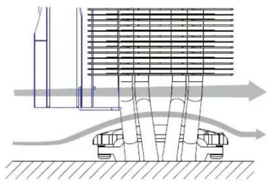
Lowering the fan helps to cool the components on the motherboard.
⑧ Connect the cooler's 4-pin connector to the motherboard's CPU Fan header.


Caution
Please make sure that PWM Control Mode is activated in the motherboard's BIOS settings.
2) AMD Socket FM1 / AM3 / AM2+ / AM2 Installation
① Unfasten the Bolts on the Cooler's Base one thread, insert the AMD A Clip between the Cover and the Base, and then refasten the Bolts.
![graph TD A["Start"] --> B["Close-up of screwdriver"] B --> C["Check for plunger"] C --> D["Adjustment to clamping"] D --> E["Adjustment to base cover"] E --> F["Make sure AMD Clip A's ingresses are flush against the protrusions of the Base Cover."] F --> G["Align"] G --> H["End"]](/content/2026/06/1265089/images/2693367647637fcee9201f627fff20444e4b99a887db704fff744cf306d5971b.jpg)
② Install Bolts to the Backplate according to the Socket Type and secure with Side Caps.

Caution
Take note of the orientation of the Nuts and the Side Caps.


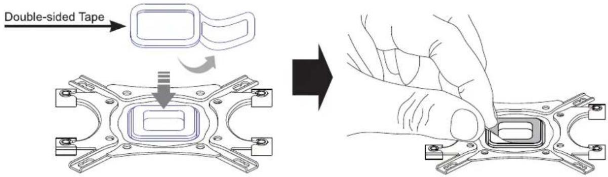
③ Remove the Sticker Cover from the Lower Tier of the Loading Block and attach to the Backplate.

Attach Double-sided Tape to the Loading Block and remove the Double-sided Tape Cover.
Caution
Please make note of the orientation of the Loading Block's Installation.

④ Disassemble the motherboard's Clip Support.

⑤ Align the Backplate's Nuts with the motherboard's Clip Support's installation holes and fasten to the motherboard.

⑥ Apply the enclosed Thermal Grease to the CPU's surface and install the Cooler by fastening the Bolts.
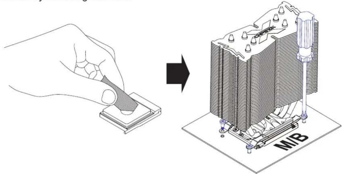
⑦ Fasten the Fan using the Fan Fixing Clips

⑧ Position the fan as low as possible.


Tip

Lowering the fan helps to cool the components on the motherboard.
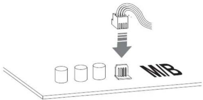
⑨ Connect the cooler's 4-pin connector to the motherboard's CPU Fan header.

Caution
Please make sure that PWM Control Mode is activated in the motherboard's BIOS settings.

- USER'S MANUAL
- CNPS10X OPTIMA
- PRECAUTIONS
- COMPONENTS
- INSTALLATION REQUIREMENTS
- SPACE REQUIREMENTS
- AIR GUIDE REMOVAL
- COOLER ORIENTATION
- CPU AND RAM INTERFERENCE CHECK (LIMITED TO SYSTEMS WITH RAM HEATSINKS)
- INSTALLATION
- CAUTION
- ③ - A SOCKET 775 INSTALLATION
- ③ - Ⓑ SOCKET 1155 / 1156 / 1366 INSTALLATION
- AMD SOCKET FM1 / AM3 / AM2+ / AM2 INSTALLATION
Marque : ZALMAN
Modèle : CNPS10X Optima
Catégorie : Refroidissement informatique