Concours 14 (2009) - Moto KAWASAKI - Notice d'utilisation et mode d'emploi gratuit
Retrouvez gratuitement la notice de l'appareil Concours 14 (2009) KAWASAKI au format PDF.


| Type de produit | Moto sport-touring |
| Marque | Kawasaki |
| Modèle | Concours 14 (GTR1400) - 2009 |
| Moteur | 4 cylindres en ligne, 4 temps, refroidissement liquide |
| Cylindrée | 1 352 cm³ |
| Alésage x course | 84 x 61 mm |
| Rapport volumétrique | 10.7:1 |
| Alimentation | Injection électronique (DFI) avec 4 papillons |
| Puissance max | 155 ch (114 kW) à 8 800 tr/min |
| Couple max | 136 Nm à 6 200 tr/min |
| Transmission | 6 vitesses, embrayage multidisque en bain d'huile |
| Transmission finale | Par arbre |
| Capacité réservoir | 22 L |
| Consommation (moyenne) | 6,5 L/100 km |
| Dimensions (L x l x H) | 2 270 x 790 x 1 375 mm |
| Empattement | 1 520 mm |
| Hauteur de selle | 815 mm |
| Poids à sec | 279 kg |
| Poids en ordre de marche | 303 kg |
| Suspension avant | Fourche inversée de 43 mm, réglable |
| Suspension arrière | Bras oscillant, mono-amortisseur réglable |
| Freins avant | 2 disques semi-flottants de 310 mm, étriers 4 pistons |
| Freins arrière | 1 disque de 270 mm, étrier 2 pistons |
| ABS | De série (K-ACT) |
| Pneu avant | 120/70-17 |
| Pneu arrière | 190/50-17 |
| Équipements principaux | Régulateur de vitesse, poignées chauffantes, top case, système K-ACT |
| Entretien régulier | Vidange moteur tous les 6 000 km, filtre à huile tous les 12 000 km |
| Batterie | 12 V - 12 Ah (type YTX12-BS) |
| Pièces détachées et réparabilité | Disponibles via réseau Kawasaki et revendeurs agréés |
FOIRE AUX QUESTIONS - Concours 14 (2009) KAWASAKI
Utilisez des pièces d'origine Kawasaki.
Questions des utilisateurs sur Concours 14 (2009) KAWASAKI
0 question sur cet appareil. Repondez a celles que vous connaissez ou posez la votre.
Poser une nouvelle question sur cet appareil
Téléchargez la notice de votre Moto au format PDF gratuitement ! Retrouvez votre notice Concours 14 (2009) - KAWASAKI et reprennez votre appareil électronique en main. Sur cette page sont publiés tous les documents nécessaires à l'utilisation de votre appareil Concours 14 (2009) de la marque KAWASAKI.
MODE D'EMPLOI Concours 14 (2009) KAWASAKI
Kawasaki
Includes:
- Important Safety Information
- Operating Instructions
- Maintenance and Storage
CONCOURS 14 ABS
CONCOURS 14
Motorcycle
OWNER'S MANUAL
WARNING
Engine exhaust, some of its constituents, and certain vehicle components contain or emit chemicals known to the State of California to cause cancer and birth defects or other reproductive harm.
NOTICE
THIS PRODUCT HAS BEEN MANUFACTURED FOR USE IN A REASONABLE AND PRUDENT MANNER BY A QUALIFIED OPERATOR AND AS A VEHICLE ONLY.
This product contains the encryption algorithm "MISTY" developed by MITSUBISHI ELECTRIC CORPORATION.
Quick Reference Guide
This Quick Reference Guide will assist you in finding the information you're looking for.
GENERAL INFORMATION
HOW TO RIDE THE MOTORCYCLE
SAFE OPERATION
MAINTENANCE AND ADJUSTMENT
STORAGE
TROUBLESHOOTING GUIDE
A Table of Contents is included after the Foreword.
Whenever you see the symbols shown below, heed their instructions! Always follow safe operating and maintenance practices.
! DANGER
DANGER indicates a hazardous situation which, if not avoided, will result in death or serious injury.
WARNING
WARNING indicates a hazardous situation which, if not avoided, could result in death or serious injury.
CAUTION
CAUTION indicates a hazardous situation which, if not avoided, could result in minor or moderate injury.
NOTICE
NOTICE is used to address practices not related to personal injury.
NOTE
○ This note symbol indicates points of particular interest for more efficient and convenient operation.
FOREWORD
Congratulations on your purchase of a new Kawasaki motorcycle. Your new motorcycle is the product of Kawasaki's advanced engineering, exhaustive testing, and continuous striving for superior reliability, safety and performance.
Please read this Owner's Manual carefully before riding so that you will be thoroughly familiar with the proper operation of your motorcycle's controls, its features, capabilities, and limitations. This manual offers many safe riding tips, but its purpose is not to provide instruction in all the techniques and skills required to ride a motorcycle safely. Kawasaki strongly recommends that all operators of this vehicle enroll in a motorcycle rider training program to attain awareness of the mental and physical requirements necessary for safe motorcycle operation.
To ensure a long, trouble-free life for your motorcycle, give it the proper care and maintenance described in this manual. For those who would like more detailed information on their Kawasaki Motorcycle, a Service Manual is available for purchase from any authorized Kawasaki motorcycle dealer. The Service Manual contains detailed disassembly and maintenance information. Those who plan to do their own work should, of course, be competent mechanics and possess the special tools described in the Service Manual.
Keep this Owner's Manual aboard your motorcycle at all times so that you can refer to it whenever you need information.
This manual should be considered a permanent part of the motorcycle and should remain with the motorcycle when it is sold.
All rights reserved. No part of this publication may be reproduced without our prior written permission.
This publication includes the latest information available at the time of printing. However, there may be minor differences between the actual product and illustrations and text in this manual.
All products are subject to change without prior notice or obligation.
KAWASAKI HEAVY INDUSTRIES, LTD. Consumer Products & Machinery Company
© 2009 Kawasaki Heavy Industries, Ltd.
Aug. 2009. (1). (S, Ke)
TABLE OF CONTENTS
SPECIFICATIONS...... 8
SERIAL NUMBER LOCATIONS...... 13
LOCATION OF PARTS.... 14
LOADING AND ACCESSORIES INFORMATION.... 17
GENERAL INFORMATION...... 21
Meter Instruments 21
Speedometer and Tachometer ..... 22
Multifunction Meter 23
Warning/Indicator Lights 55
KIPASS (Kawasaki's Intelligent Proximity Activation Start System) System.... 79
Spare FOB 93
Ignition Switch.... 95
Left Handlebar Switches 102
Dimmer Switch 102
Turn Signal Switch.... 102
Horn Button 102
Meter Mode Button 103
K-ACT ABS Button (only on equipped models).... 103
KTRC Button (only on equipped models) 103
Electric Windshield Adjusting Button 103
Right Handlebar Switches.... 104
Engine Stop Switch 104
Starter Button 105
Hazard Switch 105
Grip Warmer.... 106
Headlight Aiming Adjuster Knob ..... 108
Accessory Socket/Connectors ..... 109
Brake/Clutch Lever Adjuster 112
Fuel Tank Cap 113
Fuel Tank 114
Fuel Requirement 115
Stands 118
Seat.... 120
Special Warning on the Use of
Storage Case and Saddlebags
(Accessory).... 122
Saddlebags (Accessory) 124
Storage Case 130
Rear Carrier 132
Tool Kit Compartment.... 134
Air Intake 134
BREAK-IN 135
HOW TO RIDE THE MOTORCYCLE. 137
Starting the Engine 137
Jump Starting 139
Moving Off 142
Shifting Gears 143
Braking 145
Kawasaki Advanced
Coactive-braking Technology
(K-ACT) - Anti-lock Brake System
(ABS) for models equipped with
K-ACT ABS.... 146
K-ACT ABS Indicator Light...... 149
Stopping the Engine.... 150
Stopping the Motorcycle in an
Emergency 151
Parking 152
Catalytic Converter.... 154
Kawasaki TRaction Control (KTRC)
for models equipped with KTRC... 156
KTRC Indicator Light 157
KTRC Button 160
SAFE OPERATION.... 162
Safe Riding Technique 162
Daily Safety Checks 165
Additional Considerations for High
Speed Operation 168
MAINTENANCE AND ADJUSTMENT 170
Periodic Maintenance Chart...... 175
Engine Oil 187
Final Gear Case Oil.... 192
Cooling System 195
Spark Plugs.... 200
Evaporative Emission Control
System (California model only)..... 201
Valve Clearance 202
Kawasaki Clean Air System...... 203
Air Cleaner 204
Throttle Control System 211
Engine Vacuum Synchronization ..... 213
Idle Speed 214
Clutch 215
Brakes 217
Brake Light Switches.... 220
Front Fork 222
Rear Shock Absorber.... 226
Wheels 229
Battery 234
Headlight Beam 243
Fuses 245
General Lubrication 247
Cleaning Your Motorcycle 248
Bolt and Nut Tightening.... 254
STORAGE......257
TROUBLESHOOTING GUIDE...... 260
OWNER SATISFACTION.... 261
REPORTING SAFETY DEFECTS..... 263
ENVIRONMENTAL PROTECTION..... 264
MAINTENANCE RECORD 265
LOCATION OF LABELS.... 269
8 SPECIFICATIONS
SPECIFICATIONS
DIMENSIONS
| Overall Length | 2 230 mm (87.8 in.) |
| Overall Width(with saddlebags) | 790 mm (31.1 in.)(1 000 mm (39.4 in.)) |
| Overall Height/High Position | 1 345 mm (53.0 in.)/1 465 mm (57.7 in.) |
| Wheelbase | 1 520 mm (59.8 in.) |
| Road Clearance | 125 mm (4.92 in.) |
| Curb Mass(D) | 304 kg (670 lb)300 kg (662 lb) |
| (with saddlebags) | (312 kg (688 lb)) |
| (D) | (308 kg (679 lb)) |
ENGINE
| Type | DOHC, 4-cylinder, 4-stroke, liquid-cooled |
| Displacement | 1 352 cm ^3 (82.5 cu in.) |
| Bore × Stroke | 84.0 × 61.0 mm (3.3 × 2.4 in.) |
SPECIFICATIONS
Compression Ratio 10.7:1
Starting System Electric starter
Cylinder Numbering Method Left to right, 1-2-3-4
Firing Order 1-2-4-3
Fuel System FI (Fuel Injection)
Ignition System Battery and coil (transistorized ignition)
Ignition Timing 10° BTDC @1 100 r/min (rpm)
(Electronically advanced)
Spark Plugs NGK CR9EIA-9
Lubrication System Forced lubrication (wet sump)
Engine Oil:
Type API SG, SH, SJ, SL or SM with JASO MA, MA1 or MA2
Viscosity SAE 10W-40
Capacity 4.7 L (5.0 US qt)
Coolant Capacity 3.4 L (3.6 US qt)
TRANSMISSION
Transmission Type 6-speed, return shift
10 SPECIFICATIONS
| Clutch Type | Wet, multi disc |
| Driving System | Shaft drive |
| Primary Reduction Ratio | 1.556 (84/54) |
| Final Reduction Ratio | 2.036 (14/22 × 32/10) |
| Overall Drive Ratio | 3.402 @Top gear |
Gear Ratio:
| 1st | 3.333 (50/15) |
| 2nd | 2.412 (41/17) |
| 3rd | 1.900 (38/20) |
| 4th | 1.545 (34/22) |
| 5th | 1.292 (31/24) |
| 6th | 1.074 (29/27) |
FRAME
| Caster | 26.1° |
| Trail | 112 mm (4.4 in.) |
SPECIFICATIONS 11
Tire Size:
Front 120/70ZR17 M/C (58 W)
Rear 190/50ZR17 M/C (73 W)
Rim Size:
Front J17M/C × MT3.50
Rear J17M/C × MT6.00
Fuel Tank Capacity 22 L (5.8 US gal)
ELECTRICAL EQUIPMENT
Battery 12 V 14 Ah
Headlight:
High Beam 12 V 60 W × 2
Low Beam 12 V 55 W × 2
Tail/Brake Light LED
D: ZG1400D
Even if one of LED (Light Emitting Diode) tail/brake lights does not go on, consult with an authorized Kawasaki dealer.
12 SPECIFICATIONS
Specifications are subject to change without notice, and may not apply to every country.
SERIAL NUMBER LOCATIONS
The engine and frame serial numbers are used to register the motorcycle. They are the only means of identifying your particular machine from others of the same model type. These serial numbers may be needed by your dealer when ordering parts. In the event of theft, the investigating authorities will require both numbers as well as the model type and any peculiar features of your machine that can help them identify it.
Frame No.

natural_image
Side view of a motorcycle with mechanical components and an inset showing a component labeled 'A' (no text or symbols on the main image)A. Frame Number
Engine No.
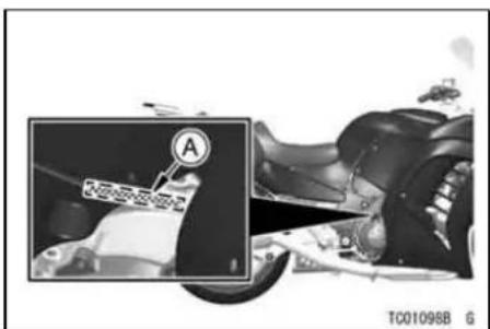
A. Engine Number
LOCATION OF PARTS
This manual is based on the vehicle equipped with the saddlebags of the accessories.
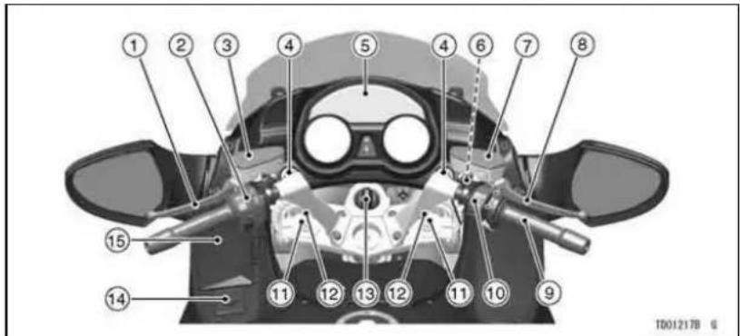
- Clutch Lever
- Left Handlebar Switches
- Clutch Fluid Reservoir
- Headlight Aiming Adjuster
- Meter Instruments
-
Accessory Socket
-
Brake Fluid Reservoir (Front)
- Front Brake Lever
- Throttle Grip
- Right Handlebar Switches
-
Spring Preload Adjuster
-
Rebound Damping Force Adjuster (Front Fork)
- Key Knob
- Grip Warmer Temperature Adjustment Dial
- Storage Case

- Air Intake
- Headlight
- Turn Signal Lights
- Spark Plugs
- Air Cleaner
- Fuel Tank
- Seat
-
Seat Lock
-
Tail/Brake Light
- License Plate Light
- Brake Disc
- Front Fork
- Brake Caliper
- Coolant Reserve Tank
- Idle Adjusting Screw
-
Shift Pedal
-
Rebound Damping Force Adjuster
- Side Stand
- Spring Preload Adjuster
- Final Gear Case
16 LOCATION OF PARTS

TD01219B G
- Saddlebag (Accessory)
- Fuse Box
- Battery
- Fuel Tank Cap
-
Windsheild
-
Muffler
- Brake Fluid Reservoir (Rear)
- Swingarm
-
Rear Brake Light Switch
-
Rear Shock Absorber
- Center Stand
- Rear Brake Pedal
- Oil Level Gauge
LOADING AND ACCESSORIES INFORMATION
WARNING
Incorrect loading, improper installation or use of accessories, or modification of your motorcycle may result in an unsafe riding condition. Before you ride the motorcycle, make sure that the motorcycle is not overloaded and that you have followed these instructions.
With the exception of genuine Kawasaki Parts and Accessories, Kawasaki has no control over the design or application of accessories. In some cases, improper installation or use of accessories, or motorcycle modification, will void the motorcycle warranty, can negatively affect performance, and can even be illegal. In selecting and using accessories, and in loading the motorcycle, you are personally responsible for your own safety and the safety of other persons involved.
NOTE
○Kawasaki Parts and Accessories have been specially designed for use on Kawasaki motorcycles. We strongly recommend that all parts and accessories you add to your motorcycle be genuine Kawasaki components.
Because a motorcycle is sensitive to changes in weight and aerodynamic forces, you must take extreme care
18 LOADING AND ACCESSORIES INFORMATION
in carrying cargo, passengers and/or in the fitting of additional accessories. The following general guidelines have been prepared to assist you in making your determinations.
-
Any passenger should be thoroughly familiar with motorcycle operation. The passenger can affect control of the motorcycle by improper positioning during cornering and sudden movements. It is important that the passenger sit still while the motorcycle is in motion and not interfere with the operation of the motorcycle. Do not carry animals on your motorcycle.
-
You should instruct any passenger before riding to keep his feet on the passenger footpegs and hold on to the operator or grab rail. Do not carry a passenger unless he or she is tall enough to reach the footpegs and footpegs are provided.
-
All baggage should be carried as low as possible to reduce the effect on the motorcycle center of gravity. Baggage weight should also be distributed equally on both sides of the motorcycle. Avoid carrying baggage that extends beyond the rear of the motorcycle.
-
Baggage should be securely attached. Make sure that the baggage will not move around while you are riding. Recheck baggage security as often as possible (not while the motorcycle is in motion) and adjust as necessary.
-
Do not carry heavy or bulky items on a luggage rack. They are designed for light items, and overloading can affect handling due to changes in weight distribution and aerodynamic forces.
LOADING AND ACCESSORIES INFORMATION
-
Do not install accessories or carry baggage that impairs the performance of the motorcycle. Make sure that you have not adversely affected any lighting components, road clearance, banking capability (i.e., lean angle), control operation, wheel travel, front fork movement, or any other aspect of the motorcycle's operation.
-
Weight attached to the handlebar or front fork will increase the mass of the steering assembly and can result in an unsafe riding condition.
-
Fairings, windshields, backrests, and other large items have the capability of adversely affecting stability and handling of the motorcycle, not only because of their weight, but also due to the aerodynamic forces
acting on these surfaces while the motorcycle is in operation. Poorly designed or installed items can result in an unsafe riding condition.
- This motorcycle was not intended to be equipped with a sidecar or to be used to tow any trailer or other vehicle. Kawasaki does not manufacture sidecars or trailers for motorcycles and cannot predict the effects of such accessories on handling or stability, but can only warn that the effects can be adverse and that Kawasaki cannot assume responsibility for the results of such unintended use of the motorcycle. Furthermore, any adverse effects on motorcycle components caused by the use of such accessories will not be remedied under warranty.
20 LOADING AND ACCESSORIES INFORMATION
Maximum Load
Weight of rider, passenger, baggage, and accessories must not exceed 228 kg (503 lb).
GENERAL INFORMATION
Meter Instruments
A. Speedometer
B. Neutral Indicator Light
C. Left Turn Signal Indicator Light
D. Warning Indicator Light
E. Multifunction Meter
F. Oil Pressure Warning Indicator Light
G. Right Turn Signal Indicator Light
H. High Beam Indicator Light
I. Red Zone
J. K-ACT ABS Indicator Light (only on equipped models)
K. KTRC Indicator Light (only on equipped models)
L. Tachometer
M. Upper Button
N. Lower Button

TG025578
22 GENERAL INFORMATION
Speedometer and Tachometer
The needle of the speedometer and tachometer momentarily sweeps from the minimum to maximum and back to minimum when the key knob is turned to "ON". This checks the operation of the meter needles, so if they do not operate correctly, have the function checked by an authorized Kawasaki dealer.
The speedometer shows the speed of the vehicle.
The tachometer shows the engine speed in revolutions per minute (r/min,
rpm). On the right side of the tachometer face is a portion called the "red zone". Engine r/min (rpm) in the red zone is above maximum recommended engine speed and is also above the range for good performance.
NOTICE
Engine r/min (rpm) should not be allowed to enter the red zone; operation in the red zone will overstress the engine and may cause serious engine damage.
GENERAL INFORMATION 23
Multifunction Meter
The multifunction meter displays the following modes.
- Odometer/Trip Meters (Trip Meter A/B)
- Clock
- Mileage (Average Mileage/Current Mileage/Cruising Range)
- Tire Air Pressure
- Battery Voltage
- Outside Temperature
- Gear Position
• Coolant Temperature Gauge - Fuel Gauge
- K-ACT ABS Standard Mode (mode 1)/High Combined Mode (mode 2) (only on equipped models)
• Economical Riding Indicator
● Fuel Economy Assistance Mode
The symbol of the key knob is displayed in the multifunction meter for 5 seconds by pushing the key knob, and when turning the key knob to ON position, "KAWASAKI" is displayed for 3 seconds, then, depending on the mode selected, the average mileage, current mileage, cruising range, tire air pressure, battery voltage or outside temperature and trip meter or odometer are displayed.

A. KAWASAKI Display
24 GENERAL INFORMATION
Pushing the upper button shifts the display though the following modes: Average Mileage (AVERAGE), Current Mileage (CURRENT), Cruising Range (RANGE), Tire Air Pressure (TIRE F/R), Battery Voltage (BATTERY) Outside Temperature (OUTSIDE).
Pushing the lower button shifts the display through the following modes: Trip Meter (TRIP A/B), Odometer (ODO).
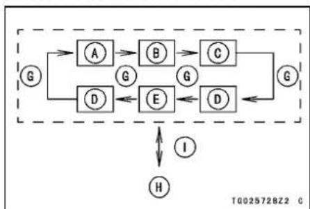
Pushing the meter mode button on the left handlebar switch housing shifts the display though the following modes: Average Mileage (AVERAGE), Current Mileage (CURRENT), Cruising Range (RANGE), Tire Air Pressure (TIRE F/R), Battery Voltage (BATTERY), Outside Temperature (OUTSIDE). Holding the meter mode button for more than one second, but less than three seconds, will turn the fuel economy assistance mode "ON/OFF".
Upper Button Function

flowchart
graph TD
    G --> A
    G --> F
    A --> B
    B --> C
    C --> D
    D --> E
    E --> F
    F --> G
A. Average Mileage (AVERAGE)
B. Current Mileage (CURRENT)
C. Cruising Range (RANGE)
D. Tire Air Pressure (TIRE F/R)
E. Battery Voltage (BATTERY)
F. Outside Temperature (OUTSIDE)
G. Push Upper Button
Lower Button Function

flowchart
graph TD
    A["A"] -->|D| B["B"]
    B -->|D| C["C"]
    C -->|D| A
    A --> T602272BZ1
A. Odometer (ODO)
B. Trip Meter (TRIP A)
C. Trip Meter (TRIP B)
D. Push Lower Button
Meter Mode Button Function
flowchart
graph TD
    G --> A
    G --> D
    A --> B
    B --> C
    D --> E
    E --> D
    C --> G
    D --> E
    E --> G
    I --> H
    H --> I
A. Average Mileage (AVERAGE)
B. Current Mileage (CURRENT)
C. Cruising Range (RANGE)
D. Tire Air Pressure (TIRE F/R)
E. Battery Voltage (BATTERY)
F. Outside Temperature (OUTSIDE)
G. Push Meter Mode Button
H. Fuel Economy Assistance Mode "ON/OFF"
I. Push and Hold Meter Made Button
GENERAL INFORMATION 25
NOTE
○Do not shift the multifunction meter display by the upper button and the lower button while riding for safe operation.
The following settings can be adjusted in the multifunction meter. When changing the settings of these items, refer to the "Setting Menu" item in this section.
● Language Setting: ENGLISH/FRANCAIS/DEUTSCH/ITALIANO
- Unit Setting (TIRE PRESSURE): KPA, PSI
● Unit Setting (MILEAGE): KM/L, L/100KM, MPG USA, MPG UK
- Unit Setting (OUTSIDE TEMP): °C, °F
- Electric Windshield Setting (WIND-SHIELD SET)
- Clock Adjustment (CLOCK)

A. Unit Display Setting in Tire Air Pressure: KPA, PSI
B. Unit Display Setting in Mileage: KM/L, L/100KM, MPG USA, MPG UK
C. Unit Display Setting in Outside Temperature: °C, °F
D. Electric Windshield Setting
E. Clock Adjustment
Odometer/Trip Meters -
"ODO"/"TRIP A"/"TRIP B"
The trip meter and odometer can be shifted to ODO, TRIP A and TRIP B by pushing the lower button.
The odometer shows the total distance in kilometers or miles that the vehicle has been ridden. This meter cannot be reset.
NOTE
○The data is maintained even if the battery is disconnected.
○When the figures come to 999999, they are stopped and locked.
○ The measurement unit of the odometer can be changed, refer to the "Setting Menu" item in this section
The trip meter shows the distance in kilometers or miles traveled since they were last reset to zero.
TRIP A:0.0 \~ 999.9
TRIP B:0 \~ 9999.9

A. ODO/TRIP A/TRIP B
GENERAL INFORMATION 27
To reset the trip meter:
- Push the lower button to display the TRIP A or TRIP B.
- Push the lower button and hold it in.

NOTE
○The data is maintained by the back up power if the ignition key is turned off.
○When the trip meter reaches 999.9 (TRIP A), or 9999.9 (TRIP B) while
28 GENERAL INFORMATION
riding, the meter resets to 0.0 and continues counting.
○When the battery is disconnected, the meter display resets to 0.0.
○ The measurement unit of the trip meter can be changed, refer to the "Setting Menu" item in this section.
Clock -
This display shows the time.
When adjusting the clock, refer to the "Setting Menu" item in this section.

A. Clock
NOTE
○The clock works normally from the back-up power while the ignition switch is turned off.
○When the battery is disconnected, the clock resets to 1:00 and starts
working again when the battery is connected.
Mileage (Average Mileage/Current Mileage/Cruising Range) -
"AVERAGE"
This display shows the average mileage by numerical value, and indicates the average fuel consumption counted from the start of measuring to present time.
GENERAL INFORMATION 29
- Push the upper button or the meter mode button to display the average mileage.
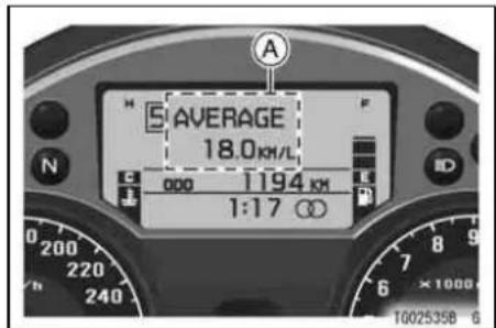
A. Average Mileage
NOTE
○ The data is maintained by back up power if the ignition key is turned off.
○ The measurement unit of the mileage can be changed, refer to the "Setting Menu" item in this section.
30 GENERAL INFORMATION
- Push the upper button for 2 seconds while the average mileage is displayed, and the average mileage resets to “—. —”.
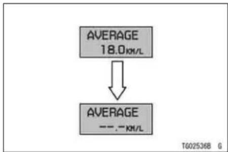
flowchart
graph TD
    A["AVERAGE 18.0 km/L"] --> B["AVERAGE ---. - km/L"]
NOTE
○When the battery is disconnected, the average mileage resets to “--.-” for a few seconds.
○After resetting the average mileage, the numerical value is not displayed until 5 mL (0.2 US oz.) of fuel has been used and 100 m (328 ft) has been traveled.
"CURRENT"
This display shows the current mileage by numerical value, and indicates the current fuel consumption. The current mileage display is renewed every 4 seconds.
- Push the upper button or the meter mode button to display the current mileage.
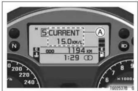
A. Current Mileage
NOTE
○ This display indicates the current fuel consumption, not average fuel consumption.
GENERAL INFORMATION 31
○ The measurement unit of the mileage can be changed, refer to the "Setting Menu" item in this section.
○The numerical value shows “--.-” until 4 seconds have passed and a speed of 5 km/h (3 mph) is reached.

A. Current Mileage
"RANGE"
This display shows the cruising range by numerical value, and indicates the cruising range from the remaining fuel
32 GENERAL INFORMATION
in the fuel tank. This cruising range display is renewed every 10 seconds.
- Push the upper button or the meter mode button to display the cruising range,

A. Cruising Range
- When the fuel tank is full, all the segments (6 segments) in the fuel gauge are displayed, and then, (+) is added to the numerical value of the cruising range.

A. “(+)” Display
- When only last 1 segment (E) flashes in the fuel gauge, the fuel warning message "FUEL LOW" and fuel warning symbol are displayed alternately in the multifunction meter
instead of the numerical value of the cruising range.
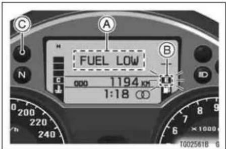
A. "FUEL LOW" Display
B. Fuel Gauge
GENERAL INFORMATION

A. Fuel Warning Symbol
B. Fuel Gauge
NOTE
○ The measurement unit of the cruising range can be changed, refer to the "Setting Menu" item in this section.
○ The display range for cruising range unit is 0 \~ 999.
34 GENERAL INFORMATION
Tire Air Pressure -
"TIRE F/R"
This display shows the tire air pressure. This value displayed in this meter is shown by riding at approx. 20 km/h (12 mph) or more and 1 minute passed.
This display is for indicator message if the tire air pressure is not low while riding.
TIRE F: Front tire air pressure
TIRE R: Rear tire air pressure
- Push the upper button or the meter mode button to display the tire air pressure.

A. Tire Air Pressure
NOTE
○The tire air pressure can be displayed up to 350 kPa (50 psi).
○Do not refer to the value of the tire air pressure displayed in this meter for measuring the tire air pressure.
GENERAL INFORMATION 35
Because this value may not show the value of the actual tire air pressure. This value should be referred only while riding.
The value of the tire air pressure displayed in this meter may show higher or lower value than the standard tire air pressure. When measuring the tire air pressure, refer to the Wheel section of the "Maintenance and Adjustment" chapter.
○ The measurement unit of the tire air pressure can be changed, refer to the "Setting Menu" item in this section.
○ When replacing the wheel, check the tire air pressure is displayed.
○ The tire air pressure sensor has the radio wave. In noisy area or high -intensity radio wave area, the tire air pressure may not display correctly.
○ If the tire air pressure is not correctly displayed while riding, have the tire
air pressure sensor checked by an authorized Kawasaki dealer.
Battery Voltage -
"BATTERY"
This display shows the battery voltage.
- Push the upper button or the meter mode button to display the battery voltage.

A. Battery Voltage
36 GENERAL INFORMATION
NOTE
○The battery voltage may not be displayed correctly in this meter when the battery voltage is less than 9.0 V or more than 16.0 V.
○ The battery voltage shown in this display may differ from the numerical value measured by the another device.
Outside Temperature -
This display shows the outside temperature by numerical value. The outside temperature display is renewed every 5 seconds.
- Push the upper button or the meter mode button to display the outside temperature.
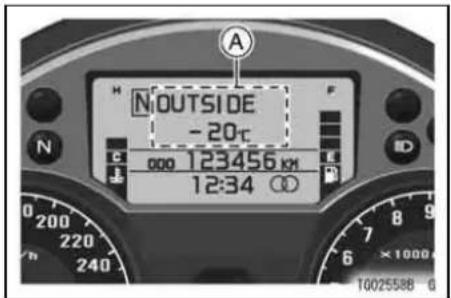
A. Outside Temperature
NOTE
○The outside temperature can be displayed from -20^ (4°F) to 60^ (140°F).
○The outside temperature may not be displayed correctly in this meter
when the vehicle stops, or the speed is 20 km/h (12 mph) or less, or immediately after engine start.
○ The measurement unit of the outside temperature can be changed, refer to the "Setting Menu" item in this section.
Gear Position -
This display shows the corresponding gear position when the transmission is shifted. As the transmission is shifted, the corresponding gear position (1st \~ 5th, OD) is shown in this display. When the transmission is in neutral, "N" is displayed, and the neutral indicator light goes on.
GENERAL INFORMATION 37
1: When the transmission is in 1st gear, "1" is displayed.
2: When the transmission is in 2nd gear, "2" is displayed.
3: When the transmission is in 3rd gear, "3" is displayed.
4: When the transmission is in 4th gear, "4" is displayed.
5: When the transmission is in 5th gear, "5" is displayed.
OD: When the transmission is in Over Drive gear, "OD" is displayed.
38 GENERAL INFORMATION

A. Gear Position
B. Neutral Indicator Light
NOTE
○If the gear position display in the multifunction meter shows “☐”, the transmission is not properly shifted to 1st. Be sure to shift the transmission.
Coolant Temperature Gauge -
The coolant temperature is shown by the number of segment currently displayed between C (cool) and H (hot). If the coolant temperature gauge is not correctly displayed, have the coolant temperature gauge checked by an authorized Kawasaki dealer. If all 6 segments are displayed and start flashing, the coolant warning message "HIGH TEMP", and the coolant warning symbol are displayed alternately in the multifunction meter, this warns the operator that the coolant temperature is too high; stop the engine and check the coolant level in the reserve tank after the engine cools down.

A. Coolant Temperature Gauge
B. "HIGH TEMP" Display
C. Warning Indicator Light
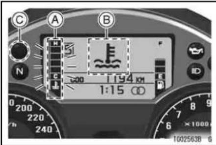
A. Coolant Temperature Gauge
B. Coolant Warning Symbol
C. Warning Indicator Light
NOTICE
Do not let the engine continue running when all the segments flash and coolant warning message/symbol are displayed. Prolonged engine operation will result in severe engine damage from overheating.
40 GENERAL INFORMATION
NOTE
When pushing the lower button with the upper button held in while the coolant warning message "HIGH TEMP" and coolant warning symbol are displayed alternately in the multifunction meter, the display in the multifunction meter is shifted to the previous display and then the warning indicator light goes on.
The coolant warning message and coolant warning symbol are displayed by rolling the message in the multifunction meter when more than two warning messages and warning symbols in the multifunction meter are displayed. When rolling the warning message and warning symbol, the warning message shifts to the other warning message by pushing the upper button.
Fuel Gauge -
The fuel in the fuel tank is shown by the number of segments displayed. When the fuel tank is full, all 6 segments are displayed.
If the fuel gauge is not correctly displayed, have the fuel gauge checked by an authorized Kawasaki dealer.

A. Fuel Gauge
As the fuel level in the tank goes down, the segments disappear one by one from F (full) to E (empty). When
the last segment (E) is displayed in the fuel gauge, the fuel warning message "FUEL LOW" and the fuel warning symbol are displayed alternately in the multifunction meter. This indicates that the remaining in the tank is 4.0 L (1.1 US gal). Refuel at the earliest opportunity if the last 1 segment (E) and fuel warning message and fuel warning symbol are displayed in the multifunction meter.
When vehicle stands with Side Stand, Fuel Gauge cannot show the amount of fuel in the fuel tank exactly. Stand upright the vehicle to check the fuel level.

A. "FUEL LOW" Display
B. Fuel Gauge
C. Warning Indicator Light
42 GENERAL INFORMATION

A. Fuel Warning Symbol
B. Fuel Gauge
C. Warning Indicator Light
NOTE
When pushing the lower button with the upper button held in while the fuel warning message "FUEL LOW" and fuel warning symbol are displayed alternately in the multifunction meter, the display in the multifunction meter is shifted to the previous display and
then the warning indicator light goes on.
The fuel warning message and fuel warning symbol are displayed by rolling the message in the multifunction meter when more than two warning messages and warning symbols in the multifunction meter are displayed. When rolling the warning message and warning symbol, the warning message shifts to the other warning message by pushing the upper button.
K-ACT ABS Standard Mode (mode 1)/High Combined Mode (mode 2) for models equipped with K-ACT ABS -
There are two K-ACT ABS modes (mode 1, mode 2) where braking effort is different depending on individual taste or running conditions. For more detailed information about the K-ACT system, see the Kawasaki Advanced
Coactive-braking Technology (K-ACT) Anti-lock Brake System (ABS) section in the How to Ride the Motorcycle chapter.

A. K-ACT ABS Symbol (mode 1) B. K-ACT ABS Symbol (mode 2)
Standard Mode (mode 1): (State level of front brake pressure here. Example: More front brake pressure) Best suitable on winding roads.
GENERAL INFORMATION 43
High Combined Mode (mode 2): (State level of front brake pressure here. Example: Less front brake pressure) Best suitable for touring, carrying a passenger, and the expressway.
- Pushing the K-ACT ABS button on the left handlebar switch housing shifts the K-ACT ABS modes.
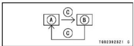
flowchart
graph TD
    A["A"] -->|C| B["B"]
    B -->|C| A
A. Standard Mode (mode 1)
B. High Combined Mode (mode 2)
C. Push K-ACT Button
NOTE
○ The mode can only be changed when the vehicle stopped.
○ The mode setting is maintained the ignition switch is turned off.
44 GENERAL INFORMATION
When the K-ACT ABS indicator light is flashing, the K-ACT ABS has been in the low voltage mode (the battery voltage decreases). When it is in the low voltage mode, the K-ACT system does not function, but the ABS functions. The ignition switch is turned off to recover the K-ACT system. At this time, the battery must be in the normal condition. If the low voltage mode continues, you should have the K-ACT ABS checked by an authorized Kawasaki dealer.
When the battery voltage is low, the K-ACT ABS mode may not be able to be changed. The ignition switch must be turned off to recover the function.
Economical Riding Indicator and Fuel Economy Assistance Mode -
Economical Riding Indicator
When the operator chooses to ride in the fuel economy assistance mode for optimum fuel-efficiency, the economical riding indicator appears on the multifunction meter to indicate favorable fuel consumption. Monitoring the economical riding indicator can help the rider maximize fuel efficiency.

A. Economical Riding Indicator
WARNING
Failing to properly observe the road ahead increases the chance of an accident resulting in severe injury or death. Do not concentrate on the economical riding indicator by taking your eyes off the road; observe using peripheral vision.
Fuel Economy Assistance Mode
This motorcycle is equipped with a fuel economy assistance mode that helps maximize fuel efficiency. Activating the fuel economy assistance mode changes to a leaner fuel injection map that prioritizes fuel economy over rideability. The fuel economy assistance mode can be activated using the meter
GENERAL INFORMATION 45
mode button on the left switch housing when rpm is less than 6 000, throttle position is less than 30 percent and vehicle speed is less than 250 km/h (152 mph). When the fuel economy assistance mode function is effective, the fuel economy assistance indicator appears on the multifunction meter.

A. Fuel Economy Assistance Indicator
46 GENERAL INFORMATION
- Push and hold the meter mode button for more than one second, but less than three seconds, will turn the fuel economy assistance mode "ON/OFF".

A. Meter Mode Button
NOTE
○Rider input affects vehicle fuel efficiency. Fuel consumption may not change due to sudden start or quick acceleration.
○Activating the fuel economy assistance mode decreases horsepower.
Setting Menu
The various settings in the multifunction meter can be performed in this setting menu.
NOTE
○ This setting menu cannot be shifted while riding. Operate this setting menu with the vehicle stopped.
Language Setting: ENGLISH/FRANCAIS/DEUTSCH/ITALIANO -
The language displayed in the multifunction meter can be changed among English, French, German and Italian in this Language Setting Menu.
- Push the upper button and lower button simultaneously for 2 seconds.
- Align the cursor and select language to display by pushing the lower button.
- Push the upper button, if advancing to the setting menu for changing the unit of the mileage and the tire air pressure, or adjusting the clock.
- Push the upper button and lower button simultaneously for 2 seconds, if not advancing to the other setting menu.

A. Language Setting Menu
B. Cursor
48 GENERAL INFORMATION
Unit Setting: KPA, PSI -
"TIRE PRESSURE"
The unit setting in the multifunction display can be changed according to local regulations. Make sure the unit setting is correctly displayed before riding.

A. Unit Setting Menu for Tire Air Pressure
B. Cursor
- Push the upper button to align the cursor to "TIRE PRESSURE" after
setting the language in the language setting menu.
- Hold the upper button in for 2 seconds, and then the previous unit setting of "TIRE PRESSURE" starts flashing.
- Select the unit to display by pushing the lower button.
- The unit shifts as the following order.

flowchart
graph TD
    A["A"] -->|C| B["B"]
    B -->|C| A
A. KPA
B. PSI
C. Push Lower Button
- Push the upper button to set the display unit after setting.
GENERAL INFORMATION 49
NOTE
○Do not operate the vehicle with the multifunction meter displaying in the wrong unit.
○ After changing the unit in the setting menu, the tire air pressure unit in the multifunction meter is also changed.
Unit Setting: KM/L, L/100KM, MPG USA, MPG UK -
"MILEAGE"
The unit setting in the multifunction display can be changed according to local regulations. Make sure the unit setting is correctly displayed before riding.

A. Unit Setting Menu for Mileage
B. Cursor
- Push the upper button to align the cursor to "MILEAGE" after setting
50 GENERAL INFORMATION
the language in the language setting menu.
- Hold the upper button in for 2 seconds, and then the previous unit setting of "MILEAGE" starts flashing.
- Select the unit to display by pushing the lower button.
● The unit shifts as the following order.

flowchart
graph TD
    A["A"] -->|E| B["B"]
    B -->|E| C["C"]
    C -->|E| D["D"]
    D -->|E| A
    A -->|E| D
A. KM/L
B. L/100KM
C. MPG USA
D. MPG UK
E. Push Lower Button
- Push the upper button to set the display unit after setting.
NOTE
○Do not operate the vehicle with the multifunction meter displaying in the wrong unit.
○After changing the distance unit in the setting menu, the odometer, trip meters and mileage unit in the multifunction meter are also changed.
Unit Setting: °C, °F -
"OUTSIDE TEMP"
The unit setting in the multifunction display can be changed according to local regulations. Make sure the unit setting is correctly displayed before riding.

A. Unit Setting Menu for Outside Temperature
B. Cursor
GENERAL INFORMATION 51
- Push the upper button to align the cursor to "OUTSIDE TEMP" after setting the language in the language setting menu.
- Hold the upper button in for 2 seconds, and then the previous unit setting of "OUTSIDE TEMP" starts flashing.
- Select the unit to display by pushing the lower button.
● The unit shifts as the following order.

flowchart
graph TD
    A["A"] -->|C| B["B"]
    B -->|C| A
A. °C
B. °F
C. Push Lower Button
- Push the upper button to set the display unit after setting.
52 GENERAL INFORMATION
NOTE
○Do not operate the vehicle with the multifunction meter displaying in the wrong unit.
○After changing the unit in the setting menu, the outside temperature unit in the multifunction meter is also changed.
Electric Windshield -
"WINDSHIELD SET"
This setting menu can be used to set the initial position of the windshield. The initial position of the windshield can be selected from 4 standard positions.
| 1 | Bottom Position (Basic Position) |
| 2 | Middle Position |
| 3 | 3/4 from Bottom Position |
| 4 | Top Position |
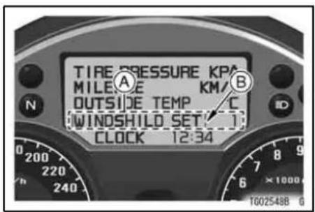
A. Electric Windshield Setting Menu
B. Cursor
- Push the upper button to align the cursor to "WINDSHIELD SET" after setting the language in the language setting menu.
- Hold the upper button in for 2 seconds, and then the previous unit setting of "WINDSHIELD SET" starts flashing.
GENERAL INFORMATION 53
- Select the initial position of the windshield from any of the standard 4 positions by pushing the lower button.
- The setting position shifts in the following order.

flowchart
graph TD
    1["1"] -->|A| 2["2"]
    2 -->|A| 3["3"]
    3 -->|A| 4["4"]
    4 -->|A| 1
    1 --> A
    2 --> A
    3 --> A
    4 --> T6025498Z1_G
A. Push Lower Button
- Push the upper button to set the display unit after setting.
NOTE
○ When the engine starts, the wind-shield moves to the set position automatically.
○If the ignition switch is turned to "ON" soon after it is turned to "OFF", the windshield may not move correctly. Turn the ignition switch to "OFF" again to move the windshield to a correct position.
WARNING
Windshield movement can trap the hands and fingers and cause injury. When the ignition switch is turned to the "OFF" position, the windshield automatically moves to the "basic" (bottom) position. Be sure nobody is adjacent to the windshield when switching the ignition to "OFF."
54 GENERAL INFORMATION
Clock -
"CLOCK"
- Push the upper button to align the cursor to the "CLOCK" after setting language in the language setting menu.

A. Clock Setting Menu
B. Cursor
- Push the upper button and hold it in for 2 seconds. Both the hour and minute displays start flashing.

- Push the lower button. When only the hour display flashes, push the upper button to advance the hours.
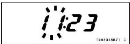
- Push the lower button. The hour display stops flashing and the minute display starts flashing. Push the upper button to advance the minutes.
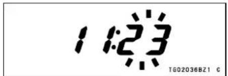
- Push the lower button. Both the hour and minute displays start flashing again.
- Push the upper button. The displays stop flashing and the clock starts working.
NOTE
○Pushing the upper button advances the hours or minutes step by step.
GENERAL INFORMATION 55
Pushing and holding the button advances the hours or minutes continuously.
○The clock works normally from the back-up power while the ignition switch is turned off.
When the battery is disconnected, the clock resets to 1:00 and starts working again when the battery is connected.
Warning/Indicator Lights
N : When the transmission is in neutral, the neutral indicator light goes on.
ID : When the headlight is on high beam, the high beam indicator light goes on.
: When the turn signal switch is pushed to the left or right, the turn signal indicator light flashes.
56 GENERAL INFORMATION
(For models equipped with K-ACT ABS)
The K-ACT ABS indicator light in the tachometer goes on when the ignition switch is turned on and goes off shortly after the motorcycle starts moving. If the K-ACT ABS is normal, it stays off. If something is fault with the K-ACT ABS, the indicator goes on and remains lit. You should have the K-ACT ABS checked by an authorized Kawasaki dealer. When the K-ACT ABS indicator light is on, the K-ACT ABS does not function but if the K-ACT ABS fails, the conventional brake system will still work normally.
For more detailed information about the K-ACT ABS, see the Kawasaki Advanced Coactive-braking Technology (K-ACT) Anti-lock Brake System (ABS) section in the HOW TO RIDE THE MOTORCYCLE chapter.
(For models equipped with KTRC)
KTRC : The KTRC indicator light in the tachometer shows the operating state of the KTRC. For more detailed information about KTRC, see the Kawasaki TRaction Control (KTRC) section in the HOW TO RIDE THE MOTORCYCLE chapter.
: The oil pressure warning indicator light goes on whenever the oil pressure is dangerously low or the ignition key is in the ON position with the engine not running, and goes off when the engine oil pressure is high enough. Refer to the Maintenance and Adjustment chapter for more detailed engine oil information.
Warning Indicator Light: The warning indicator light goes on or flashes with the meter message display whenever a problem occurs in digital fuel injection (DFI), or KIPASS system. Refer to the
following each instructions for more detailed information with the meter message.
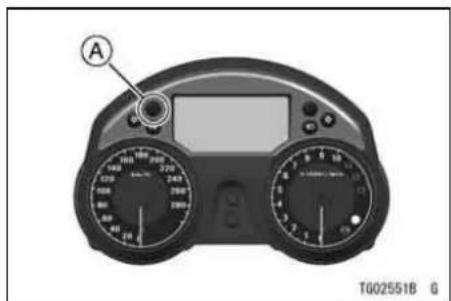
A. Warning Indicator Light
NOTE
○ When pushing the lower button with the upper button held in while the warning message and warning symbol without the warning light are displayed alternately in the multifunction
GENERAL INFORMATION 57
meter, the display in the multifunction meter is shifted to the previous display and warning indicator light goes on for noticing the warning message leaves.
The warning message and warning symbol are displayed by rolling the message in the multifunction meter when more than two warning messages and warning symbols in the multifunction meter are displayed. When rolling the warning message and warning symbol, the warning message shifts to the other warning message by pushing the upper button.
- When the key is turned to "OFF", the warning indicator light will start flashing indicating that the immobilizer system is enabled. After 24
58 GENERAL INFORMATION
hours have passed, the warning indicator light will stop flashing; however the immobilizer system is still enabled.
- The warning indicator light flashes if an improperly coded key is used, or any incorrect communication between antenna and key has occurred. However, when a properly coded key is used, and the communication is clear, the warning indicator light does not flash.
NOTE
○Warning indicator light flashing mode can be set to either ON or OFF. Push and hold the upper and lower buttons simultaneously for more than two seconds, within twenty seconds of turning the ignition key to the "OFF"
position, then the warning indicator light will not flash.
The warning indicator light flashing mode cannot be changed if it is indicating a problem with the fuel injection system or KIPASS system. If the warning indicator light flashing mode cannot be disabled, there may be a problem with the fuel injection or immobilizer system. In this case, have fuel injection system or KIPASS system checked by an authorized Kawasaki dealer.
○When the battery is connected, warning indicator light defaults to flashing mode.
When the battery voltage is low (below 12 V), warning indicator light flashing automatically stops to prevent excessive battery discharge.
FI Warning Message/FI Warning Symbol -
The warning message and warning symbol are displayed with the warning indicator light whenever a problem occurs in digital fuel injection system (DFI). If troubles occur in the digital fuel injection system, the warning indicator light goes on or flashes and FI warning message "FI ERROR" and FI warning symbol are displayed alternately in the multifunction meter. If the warning indicator light goes on or flashes, and warning message and warning symbol are displayed, have DFI system checked by an authorized Kawasaki dealer.

A. "FI ERROR" Message B. Warning Indicator Light
60 GENERAL INFORMATION

A. Warning Symbol
B. Warning Indicator Light
When the warning message "ECU ID ERROR" and warning symbol are displayed with the warning indicator light, this warns that the FI ECU is not correctly communicated. Have FI ECU checked by an authorized Kawasaki dealer.

A. "ECU ID ERROR" Message B. Warning Indicator Light
A. Warning Symbol
B. Warning Indicator Light
GENERAL INFORMATION 61
Immobilizer Warning Message/Warning Symbol -
The warning message and warning symbol are displayed with the warning indicator light whenever a problem occurs in immobilizer system. If troubles occur in the immobilizer system, the warning indicator light goes on or flashes and immobilizer warning message "IMMOBILIZER ERROR" and warning symbol are displayed alternately in the multifunction meter. If the warning indicator light goes on or flashes, and warning message and warning symbol are displayed, have immobilizer system checked by an authorized Kawasaki dealer.
62 GENERAL INFORMATION
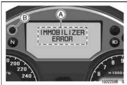
A. "IMMOBILIZER ERROR" Message
B. Warning Indicator Light

A. Warning Symbol
B. Warning Indicator Light
Steering Lock Warning Message/Warning Symbol -
The warning message and warning symbol are displayed with the warning indicator light whenever a problem occurs in ignition switch unit. If troubles occur in the ignition switch unit, the warning indicator light goes on and steering lock warning message "STEERING LOCK ERROR" and warning symbol are displayed alternately in the multifunction meter. If the warning indicator light goes on, and warning message and warning symbol are displayed, have the ignition switch unit checked by an authorized Kawasaki dealer.

A. "STEERING LOCK ERROR" Message B. Warning Indicator Light
64 GENERAL INFORMATION
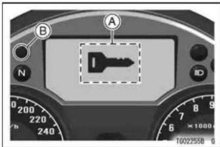
A. Warning Symbol
B. Warning Indicator Light
When the warning message "STEERING LOCK ID ERROR" and warning symbol are displayed with the warning Indicator light, this warns that the ignition switch unit is not correctly communicated. Have the ignition switch unit checked by an authorized Kawasaki dealer.

A. "STEERING LOCK ID ERROR" Message B. Warning Indicator Light

A. Warning Symbol
B. Warning Indicator Light
GENERAL INFORMATION 65
Tire Air Pressure Sensor Warning Message/Warning Symbol -
The warning message and warning symbol are displayed with the warning indicator light whenever a problem occurs in the tire air pressure sensor. If troubles occur in the tire air pressure sensor, the warning Indicator light goes on or flashes and the tire air pressure sensor warning message and warning symbol are displayed alternately in the multifunction meter. If the warning indicator light goes on or flashes, and warning message and warning symbol are displayed, have the tire air pressure sensor checked by an authorized Kawasaki dealer.
TIRE PRESSURE SENSOR : F ERROR: Front tire pressure sensor trouble
TIRE PRESSURE SENSOR : R ERROR: Rear tire pressure sensor trouble
66 GENERAL INFORMATION

A. Tire Air Pressure Sensor Warning Message (Front Tire)
B. Warning Indicator Light

A. Warning Symbol
B. Warning Indicator Light
Tire Air Pressure Warning Message/Warning Symbol -
The warning message and warning symbol are displayed with the warning indicator light instead of the numerical value of the tire air pressure when the tire air pressure is approx. 220 kPa (32 psi) or less. This warns the operator that the tire air pressure is low. Measure the tire air pressure following the instruction of Wheel section of the "Maintenance and Adjustment" chapter at the earliest opportunity. When the sensor recognizes that tire air pressure is approx. 230 kPa (33 psi) or more, tire air pressure warning message and warning symbol disappear.
LOW PRESSURE TIRE F: Front tire air pressure is low.
LOW PRESSURE TIRE R: Rear tire air pressure is low.

A. Tire Air Pressure Warning Message (Front Tire)
B. Warning Indicator Light

A. Warning Symbol
B. Warning Indicator Light
NOTE
○The tire air pressure warning message and warning symbol are displayed till the tire air pressure is approx. 230 kPa (33 psi).
○When replacing the wheel, check the tire air pressure is correctly displayed.
Tire Air Pressure Sensor Battery Warning Message/Warning Symbol -
The warning message and warning symbol are displayed when the battery voltage of the tire air pressure sensor is low. If this warning message and warning symbol are displayed, the air pressure sensor should be consulted by an authorized Kawasaki dealer.
TIRE PRESSURE SENSOR : F LOW BATTERY: Front tire air pressure sensor battery is low.
TIRE PRESSURE SENSOR : R LOW BATTERY: Rear tire air pressure sensor battery is low.

A. Tire Air Pressure Sensor Battery Warning Message (Front Side)
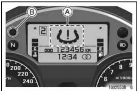
A. Warning Symbol
NOTE
○ When tire pressure sensor battery is discharged, each tire pressure warning messages and symbol is not displayed.
70 GENERAL INFORMATION
K-ACT ABS Warning Message/Warning Symbol for models equipped with K-ACT ABS -
The warning message and warning symbol are displayed with the warning indicator light whenever a problem occurs in the K-ACT ABS. If troubles occur in the K-ACT ABS, the warning indicator light goes on or flashes and the K-ACT ABS warning message and warning symbol are displayed alternately in the multifunction meter. If the warning indicator light goes on or flashes, and warning message and warning symbol are displayed, have the K-ACT ABS checked by an authorized Kawasaki dealer.
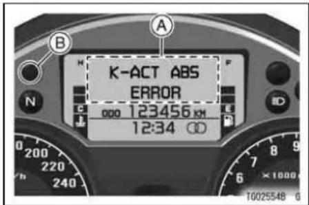
A. K-ACT ABS Warning Message B. Warning Indicator Light
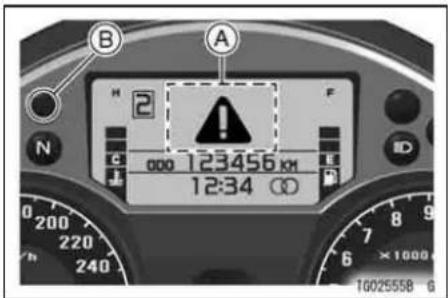
A. Warning Symbol
B. Warning Indicator Light
GENERAL INFORMATION 71
KTRC Warning Message/Warning Symbol for models equipped with KTRC -
The warning message and warning symbol are displayed with the warning indicator light whenever a problem occurs in the KTRC. If troubles occur in the KTRC, the warning indicator light goes on or flashes and the KTRC warning message and warning symbol are displayed alternately in the multifunction meter. If the warning indicator light goes on or flashes, and warning message and warning symbol are displayed, have the KTRC checked by an authorized Kawasaki dealer.
72 GENERAL INFORMATION
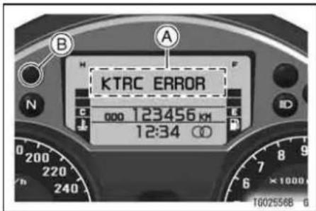
A. KTRC Warning Message
B. Warning Indicator Light

A. Warning Symbol
B. Warning Indicator Light
GENERAL INFORMATION 73
FOB Warning Message/Warning Symbol -
The warning message and warning symbol are displayed in the multifunction meter when the engine stops/the motorcycle goes away without carrying the FOB (portable key), battery voltage is discharged, or the FOB can not correctly certified.
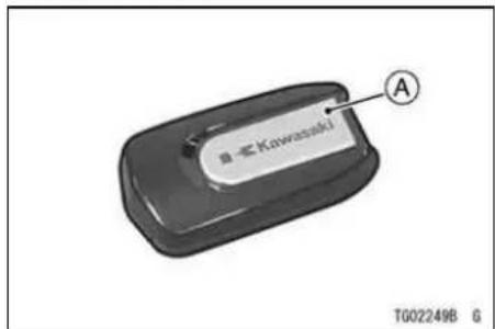
A. FOB (Portable Key)
The warning message "NO TRANSPONDER" is displayed with the warning indicator light, then warning symbol are displayed in the multifunction meter for 10 seconds. This warns that the FOB is not near the motorcycle and the engine can be started again while displaying the warning symbol in the multifunction meter.
If the motorcycle goes away with the FOB left, the warning message is displayed. If the warning message is displayed, check where the FOB is after the motorcycle stops.
This waning message is displayed when the motorcycle goes away with the FOB left, and the engine speed is over 20 km/h (12 mph), moreover the vehicle speed has the stable acceleration.
74 GENERAL INFORMATION
NOTICE
The engine can not be started when the warning symbol display became to off after 10 seconds passed. If the motorcycle can not be started after the warning symbol is displayed for 10 seconds, use the spear FOB or consult an authorized Kawasaki dealer for starting the engine.
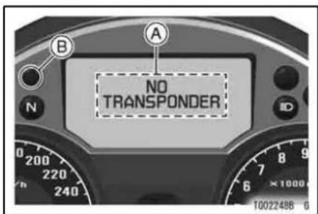
A. "NO TRANSPONDER" Message
B. Warning Indicator Light

A. Warning Symbol
B. Warning Indicator Light
GENERAL INFORMATION 75
When the warning message "SUBKEY ID ERROR" and warning symbol are displayed with the warning indicator light, this warns that the FOB is not correctly communicated when bringing the FOB to the ignition switch within 2 cm (0.8 in.) with the battery of the FOB discharged.
Check that the range between the FOB and ignition switch is 2 cm (0.8 in.), or use the spare FOB. If the warning message and warning symbol are still displayed, it should be done by an authorized Kawasaki dealer.
GENERAL INFORMATION
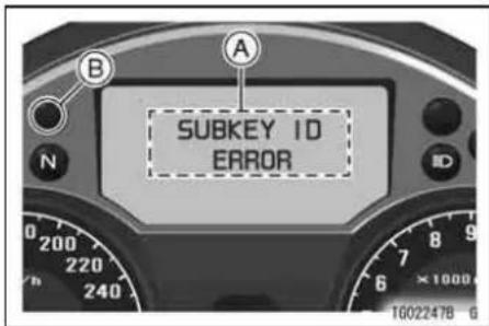
A. "SUBKEY ID ERROR" Message
B. Warning Indicator Light

A. Warning Symbol
B. Warning Indicator Light
When the warning message "TRANSPONDER LOW BATTERY" and warning symbol are displayed in the multifunction meter after turning the key knob to ON position, this warns that battery voltage of the FOB is low. If the warning message and warning symbol is displayed in the multifunction meter, replace the battery to the new one at the earliest opportunity. Refer to the KIPASS System section in this chapter for the replacement and detail information of the battery.
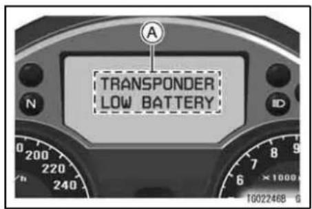
A. "TRANSPONDER LOW BATTERY" Message
78 GENERAL INFORMATION
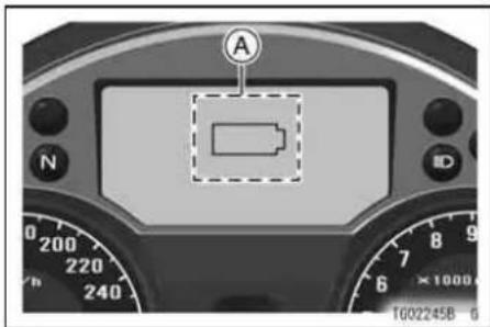
A. Warning Symbol
with the battery of the FOB discharged, "NO TRANSPONDER" and "TRANSPONDER LOW BATTERY" message is not displayed in the multifunction meter when turning the key knob to OFF position, and "NO TRANSPONDER" message is not displayed in the multifunction meter even if the motorcycle goes away with the FOB left.
NOTE
When the battery voltage of the FOB is discharged, "TRANSPONDER LOW BATTERY" message is not displayed in the multifunction meter.
○If the key knob is turned to ON position by bringing the FOB to the ignition switch within 2 cm (0.8 in.)
GENERAL INFORMATION 79
KIPASS (Kawasaki's Intelligent Proximity Activation Start System) System
This motorcycle has the KIPASS system, which can start the engine and lock the steering without taking out the ignition key by only carrying the FOB (portable key).
This system contains of the FOB, KIPASS ECU, Key Knob.
NOTE
○ When the battery is discharged or taken off from the motorcycle, this system can not lock or unlock the steering lock.
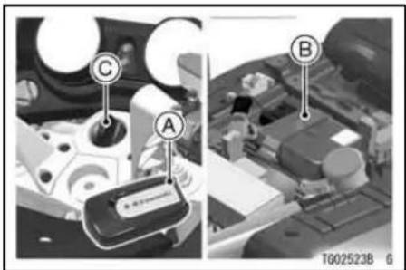
A. FOB (Portable Key)
B. KIPASS ECU
C. Key Knob
80 GENERAL INFORMATION
Starting the engine -
This system can start the engine by the user ID certification (mutual certification between the motorcycle and FOB is performed by radio wave, and certifies if the FOB is properly coded for the motorcycle).
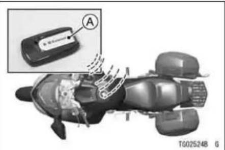
A. FOB (Portable Key)
WARNING
KIPASS system may interfere with the operation of certain medical devices such as implanted pacemakers and implanted cardiac defibrillators. The FOB or KIPASS ECU must be kept more than 22 cm (9 in.) from these type of medical devices to avoid interference. Do not carry the KIPASS FOB in your breast pocket. Operators with medical devices such as pacemakers and implanted cardiac defibrillators should consult with their doctors before use.

A. FOB (Portable Key) B. KIPASS ECU (Under Seat)
GENERAL INFORMATION 81
FOB (Portable Key) -
The FOB of this motorcycle has the emergency ignition key (mechanical key). The emergency ignition key should be inserted into the FOB. When the key knob is lost, etc, the ignition key can be used as the emergency key. Up to six FOB can be registered with the KIPASS system at one time. Registering additional FOB should be done by an authorized Kawasaki dealer. If all FOB are lost, registering new codes for replacement FOB into electronic control unit is impossible. To make additional user keys, take the vehicle along with the all FOB to authorized Kawasaki dealer to have them re-registered.
82 GENERAL INFORMATION
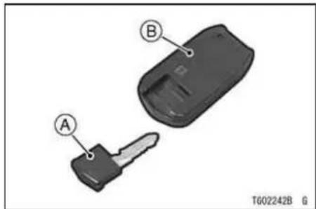
A. Emergency Ignition Key (Mechanical Key) B. FOB
Information for Use of FOB
- If the FOB is put on the other metal surface, or touch to the other metal materials, incorrect communication between ECU and FOB may be occurred.
- When the FOB is within the possible area of the radio wave starting the engine, note that anyone can start
the engine (even if the person does not possess the FOB).
- When parking the motorcycle across the glass window, or house wall, the location may be within the possible area of the radio wave.
- The rider should possess the FOB while riding, do not leave the FOB in the saddlebag, or storage case, etc, for antitheft, and make sure to check that there is the FOB before stopping the engine.
- FOB transmits and receives the radio wave, so the battery in the FOB discharges. The normal battery life is for about 1 years depending on the situation of the use. If the FOB is close to the manufacture developing the strong radio wave (TV, Personal Computer), the battery life may discharge earlier. The FOB is communicated when the steering is unlocked,
GENERAL INFORMATION 83
turned to ON, and the motorcycle is moved off.
- If the battery of the FOB is discharged, key knob can not be operated. Remove the emergency ignition key from FOB and fit the hollow of the FOB on the projection of the ignition switch, then key knob can be operated after about 2 seconds passed when key knob is pushed.
- When possessing the several registered FOB, the engine can be started if any one FOB is correctly certified. If the communication is failed, move one of the FOB to other location.
- Even if the FOB is within the possible area of the radio wave starting the engine, the FOB may not be correctly certified. Move the motorcycle or the FOB to other place.
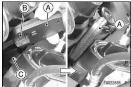
A. FOB
B. Hollow
C. Projection
NOTICE
Do not expose the FOB to excessively high temperature or more humid place.
Do not put any magnetic materials with the FOB on the same key ring.
Do not put the FOB close to the other electric appliance (TV, Audio system, Personal Computer, etc) or medical appliance.
Do not submerge FOB in water. Do not disassemble the FOB except of replacing the battery.
Do not drop the FOB or apply shocks to it.
If FOB is lost, re-registry at dealer is securely required to prevent the possibility of theft.
If all FOB are lost, an authorized Kawasaki dealer will have to replace the ECU, and re-register the new FOB.
Battery Replacement
The FOB has the battery. If the battery is discharged, the replacement of the battery should be done by an authorized Kawasaki dealer or replace it as follows.
- Insert the (−) screwdriver into the groove of the upper of the FOB, and disassemble the FOB by twisting the (−) screwdriver lightly.

A. Groove
B. Twist
C. (-) ScrewDriver
NOTE
○ When separating the FOB halves, protect top surface with towel while applying with properly size screwdriver.
GENERAL INFORMATION 85
- Replace battery, and insert securely.
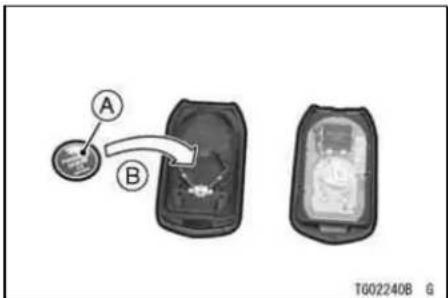
A. Battery
B. (+) Side Facing to down
Battery
CR2025
NOTICE
Battery shall not be exposed to excessive heat such as sunshine, fire or the like.
86 GENERAL INFORMATION
NOTE
○ Install the battery with (+) side of the battery facing to down.
- When assembling the FOB, align each grooves of the upper and lower case of the FOB and insert them securely.

A. Groove
B. Projection
WARNING
The FOB contains a coin-style battery and other small parts that could be ingested by a child and result in severe injury. To prevent accidental ingestion, keep the FOB battery and other small parts out of the reach of children.
NOTICE
Be careful not to damage the FOB when replacing the FOB.
Be sure to install the (+) side of battery to the correct installation.
Do not touch the electrical parts, or electrical circuit on the inside of the FOB.
Avoid to replace the battery where heavy dust is blowing.
Do not make the dust insert into the FOB.
Do not force to disassemble the FOB when replacing the battery.
Do not touch the battery or terminal of the FOB with the bare hands when replacing the battery.
GENERAL INFORMATION 87
Emergency Key Removal
The emergency key can be used as the substitute key for key knob when the key knob is lost, or etc. Remove the emergency key by pulling out it with sliding the knob to the arrow mark. Be sure to insert the emergency key into FOB when using the normal use.
NOTE
○ The emergency key should be used with the FOB. The only emergency key can not operate the ignition switch.
88 GENERAL INFORMATION
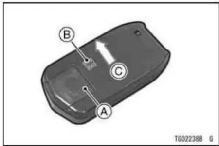
A. Emergency Key
B. Knob
C. Push
There is a key number in this emergency key. Record the number from your key.
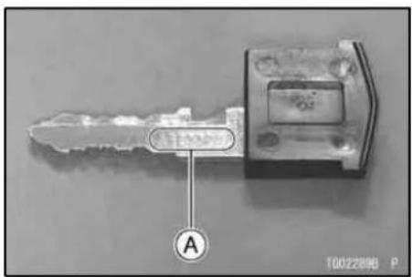
A. Key Number
natural_image
Empty white rectangle with black border (no text or symbols)Write your key number here
GENERAL INFORMATION 89
FOB Possible Radio Wave Area -
The possible communication area of the radio wave between the FOB and antenna is about 80 cm (31.5 in.). This KIPASS system uses the weak radio wave, so, the possible communication area may be different. Incorrect communication may occur by the location of the FOB, even if the FOB is located within the possible communication area.

A. Area
B. About 80 cm (31.5 in.)
90 GENERAL INFORMATION

A. Area
B. About 80 cm (31.5 in.)
KIPASS System Does Not Operate -
If KIPASS system does not operate correctly excluding the following item, KIPASS system should have been checked by an authorized KAWASAKI dealer.
- As incorrect communication occurs in such environment as the high-intensity radio wave and noisy
area (close to such the place developing strong radio wave, broadcasting station, electric power station, cellular phone, personal computer, etc, and close or covered by metal material).
- Battery is not correctly installed or discharged (refer to the battery replacement section).
Special Warning on KIPASS System
This motorcycle has the KIPASS system, which develops and receives the radio wave between FOB and antenna. Make sure that the rider or passenger applying the medical appliances of the cardiac pacemaker, implantable cardioverter defibrillator, and etc, confirm the antenna location and FOB (portable key) location before riding, and be sure to read the following warning.
WARNING
KIPASS system may interfere with the operation of certain medical devices such as implanted pacemakers and implanted cardiac defibrillators. The FOB or KIPASS ECU must be kept more than 22 cm (9 in.) from these type of medical devices to avoid interference. Do not carry the KIPASS FOB in your breast pocket. Operators with medical devices such as pacemakers and implanted cardiac defibrillators should consult with their doctors before use.
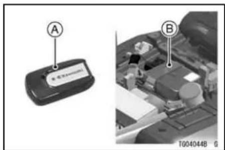
A. FOB (Portable Key)
B. KIPASS ECU (Under Seat)
92 GENERAL INFORMATION
Hereby MITSUBISHI ELECTRIC CORP. JAPAN declares that this KIPASS SYSTEM is in compliance with the essential requirements and other relevant provisions of Directive 1999/5/EC.
Hereby ASAHIDENSO CORPORATION declares that this IMMOBILIZER (KM191) is in compliance with the essential requirements and other relevant provisions of Directive 1999/5/EC.

TE036908 P
Attach the label into this space if your country requires attaching the radio wave certification label. The certification label should be consulted by an authorized Kawasaki dealer.
Spare FOB
This motorcycle has a spare FOB in addition to the primary FOB (portable electronic key). If the primary FOB is lost, the spare FOB can be used as an emergency key. The spare FOB has the emergency mechanical ignition key which should be inserted into the spare FOB. If the key knob is lost, etc, the ignition key can be used as the emergency key.

natural_image
Two mechanical components labeled A and B, one gray and one white, with no visible text or symbols on the parts themselves.A. Spare FOB
B. Emergency Ignition Key (Mechanical Key)
The spare FOB has the immobilizer function, but it does not have the KIPASS function. Therefore, when using the spare FOB, perform the following procedures.
- Fit the "Triangle Mark" corner of the spare FOB on the projection of the ignition switch so that the "Kawasaki" logo of the spare FOB faces the front, then key knob can be operated after
94 GENERAL INFORMATION
about 2 seconds when the key knob is pushed.

A. Spare FOB
B. Projection
C. "Kawasaki" Logo
D. Triangle Mark

A. Correct Position
B. Not Position

A. Not Position
GENERAL INFORMATION 95
Ignition Switch
This motorcycle has the KIPASS system, which can start the engine and lock the steering without taking out the key knob by only carrying the FOB (portable key).
This motorcycle has a four-position, key knob-operated switch. The key knob can be removed from the switch when it is in the FSS position.
NOTE
○Forcible operation of the ignition switch may cause the any malfunction. If any unexpected message is displayed, turn the key knob to OFF position, and then turn the key knob to ON, LOCK or FSS position slowly again.
96 GENERAL INFORMATION
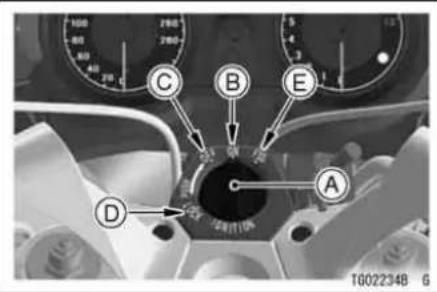
A. Key Knob
B. ON Position
C. OFF Position
D. LOCK Position
E. FSS Position
| OFF | Engine off. All electrical circuits off. Key knob can not be removed. |
| ON | Engine on. All electrical equipment can be used. Key knob can not be removed. |
| LOCK | Steering locked. Engine off. All electrical circuits off. Key knob can not be removed. |
| FSS | Steering is not locked. Engine off. All electrical circuits off. Key knob can be removed. |
NOTE
The tail, city and license plate lights are on whenever the ignition switch is in the ON position. Headlight goes on when the starter button is released after starting the engine. To avoid battery discharge, always start the engine immediately after turning the ignition switch to "ON".
○ If you leave the ON position on for a long time, the battery may become totally discharged.
To operate the ignition switch:


LOCK
-
Turn the handlebar fully to the left.
-
a. For FSS push down the key in the OFF position and turn it to FSS through the ON position.
b. For locking push down the key in the OFF position and turn it to LOCK.
TGD4073BZ2 C
GENERAL INFORMATION
WARNING
Windshield movement can trap the hands and fingers and cause injury. When the ignition switch is turned to the "OFF" position, the windshield automatically moves to the "basic" (bottom) position. Be sure nobody is adjacent to the windshield when switching the ignition to "OFF."
NOTICE
Do not leave the key knob at the FSS position for no mischief or antitheft.
Key knob should be left at the lock position when parking the motorcycle.
Kawasaki recommends that the key knob is removed at the FSS position only when opening the fuel tank, saddlebag, and removing the seat.
If the FOB is not correctly communicated when the key knob is pushed in, push the key knob again after several seconds (about 10 seconds).
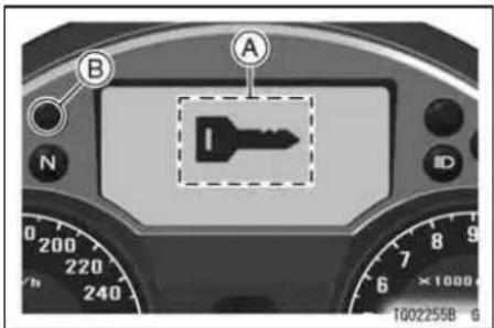
When pushing the key knob, the key knob can be turned to ON, OFF, LOCK, FSS position while the symbol of the key knob is displayed in the multifunction meter. When the key knob is pushed in, then, when turning to ON, turn signal light flashes two times, the symbol of the key knob is displayed in the multifunction meter for 5 seconds. Key knob symbol display means that the FOB is correctly certificated.
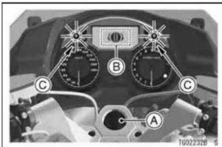
A. Key Knob
B. Symbol of Key Knob
C. Turn Signal Indicator Light Flashes Two Times
GENERAL INFORMATION 99
When turning the key knob to OFF or FSS, the turn signal light flashes one time and the symbol of the key knob is displayed in the multifunction meter for 5 seconds, and then the ignition switch can not be turned. When leaving the motorcycle, make sure the ignition switch can not be turned to any position.

A. Key Knob
B. Symbol of Key Knob
C. Turn Signal Indicator Light Flashes One Time
100 GENERAL INFORMATION
The warning message and warning symbol are displayed in the multifunction meter when the engine stops without carrying the FOB (portable key).
The warning message "NO TRANSPONDER" is displayed in the multifunction meter with the warning indicator light, then warning symbol are displayed in the multifunction meter for 10 seconds. This warns that the FOB is not near the motorcycle and the engine can be started again while displaying the warning symbol in the multifunction meter. Use the correct registered FOB by turning the key knob to ON again while displaying the warning symbol in the multifunction meter.
NOTICE
The engine can not be started when the warning symbol display became to off after 10 seconds passed.
If the motorcycle can not be started after the warning symbol is displayed for 10 seconds, use the correct Spear FOB or consult an authorized Kawasaki dealer for starting the engine.
Do not leave the motorcycle with the key knob turned to the ON position for antitheft.

A. "NO TRANSPONDER" Message
B. Warning Indicator Light

A. Warning Symbol
B. Warning Indicator Light
NOTE
○If KIPASS system is failure, steering may not be locked. Have the KIPASS system checked by an authorized Kawasaki dealer.
102 GENERAL INFORMATION
Left Handlebar Switches
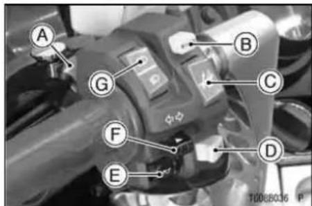
A. Meter Mode Button
B. K-ACT ABS Button (only on equipped models)
C. Electric Windshield Adjusting Button
D. KTRC Button (only on equipped models)
E. Horn Button
F. Turn Signal Switch
G. Dimmer Switch
Dimmer Switch
High or low beam can be selected with the dimmer switch. When the headlight is on high beam ( ), the high beam indicator light goes on.
High Beam…(≡D)
Low Beam…( )
Turn Signal Switch
When the turn signal switch is turned to the left ( ✦ ) or right ( ✦ ), the corresponding turn signals flash on and off.
To stop flashing, push the switch in.
Horn Button
When the horn button is pushed, the horn sounds.
GENERAL INFORMATION 103
Meter Mode Button
This button is used for selecting the various modes of the multifunction meter. Refer to the Multifunction Meter section in this chapter for more detail.
K-ACT ABS Button (only on equipped models)
This button is used for selecting the K-ACT ABS standard mode (mode 1)/high combined mode (mode 2). Refer to the Multifunction Meter section in this chapter for more detail.
KTRC Button (only on equipped models)
This button is used for selecting the operation of KTRC. Refer to the Kawasaki TRaction Control (KTRC) section in the HOW TO RIDE THE MOTORCYCLE chapter for more detail.
Electric Windshield Adjusting Button
Windshield height can be changed by electrical windshield adjusting button.
When moving the windshield up or down as the arrow mark, push and hold the adjusting button.
Windshield up…( ) Windshield down…( )

natural_image
Close-up of a motorcycle's front wheel and side mirror, labeled with point A (no text or symbols on the body)A. Windshield
104 GENERAL INFORMATION
NOTICE
Make sure all body parts, clothing or other objects are not near the movable parts of the windshield when it is being moved to avoid such items from becoming pinched or caught.
Right Handlebar Switches

A. Engine Stop Switch
B. Starter Button
C. Hazard Switch
Engine Stop Switch
In addition to the "ON" position of the key knob, the engine stop switch must be in the position for the motorcycle to operate.
The engine stop switch is for emergency use. If some emergency requires stopping the engine, move the engine stop switch to the ✗ position.
NOTE
Although the engine stop switch stops the engine, it does not turn off all the electrical circuits. Ordinarily, the ignition switch should be used to stop the engine.
Starter Button
The starter button operates the electric starter when the transmission is in neutral.
Refer to the Starting the Engine section of the HOW TO RIDE THE MOTORCYCLE chapter for starting instructions.
Hazard Switch
If an emergency requires you to park on the highway shoulder, turn on the hazard lights to warn other drivers of your location.
Push in the hazard switch to the left with the key knob in the ON position. All the turn signals and turn signal indicator lights will flash on and off.
To stop flashing, push the switch to the right.
NOTICE
Be careful not to use the hazard lights for more than 30 minutes, otherwise the battery may become totally discharged.
106 GENERAL INFORMATION
Grip Warmer
This motorcycle is equipped with temperature-adjustable grip warmers designed to heat the handlebar grips. The temperature adjustment dial is stepless between LO and HI so the rider has a wide choice of temperature settings.
To raise the temperature, turn the dial towards "HI".
To lower the temperature, turn the dial towards "LO".
Adjust the grip warmer temperature according to the ambient temperature or feeling temperature. To turn the grip warmer off, align the triangle mark on the temperature adjustment dial with "OFF".
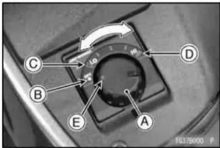
A. Temperature Adjustment Dial
B. OFF Position
C. LO Position
D. HI Position
E. Triangle Mark
WARNING
Releasing your hand(s) from the handlebar while riding may cause a crash resulting in serious injury or death. Do not operate the grip warmer while riding.
GENERAL INFORMATION
NOTICE
Always wear gloves when using the grip warmer. If the handlebar grip becomes worn or damaged, stop using the grip warmer and replace the grip with a new one. Using the grip warmer with worn or damaged grips may cause burns. On a warm day (ambient temperature 20°C (68°F) or higher), refrain from using the grip warmer. In warmer weather, keep the temperature adjustment dial near the "LO" position.
108 GENERAL INFORMATION
Battery Protection -
- This grip warmer is equipped with the automatic shift switch to prevent the battery from running down. Therefore, when the motorcycle is at a stop or is slowing down, the switch may be turned off automatically. Once the motorcycle returns to normal operating speed, the switch is turned on automatically.
● During the motorcycle is traveling at extremely low speed, the automatic shift switch may not be turned on depending on the battery condition. - Batteries are consumable goods. If the lifetime of the battery is at the end, the grip warmer cannot operate. Inspect the battery and replace it with a new one.
Headlight Aiming Adjuster Knob
The headlight aiming is adjusted vertically by the adjuster knob on the near of the meter. Refer to the Headlight Beam section of the "Maintenance and Adjustment" chapter for adjusting the headlight aiming.

natural_image
Close-up of a mechanical component with labeled parts (A and G), no readable text or symbols beyond labelsA. Vertical Adjuster (Adjuster Knob)
NOTE
○ If you carry a heavier or lighter than normal load, you may need to adjust your headlight beam so you can better see the road ahead and don't blind oncoming drivers.
Accessory Socket/Connectors
The electric power of the battery can be used through the electric accessory socket or connectors. Observe and follow the notes listed below.

natural_image
Close-up of a mechanical component with a labeled section A (no readable text or symbols beyond the label)A. Accessory Socket
110 GENERAL INFORMATION
Electric Accessory Connectors
| Location | Polarity | Lead Color |
| Under Latch | (+) | Black |
| (-) | Black/Yellow | |
| Under Front Inner Cover | (+) | Black |
| (-) | Black/Yellow |
NOTICE
If using an accessory in the socket, unless it has a waterproof connection do not operate this motorcycle in the rain or wash it. Always put the cap on the socket when the accessory is not used.

natural_image
Close-up of a mechanical component with labeled parts (A) and no visible text or symbols beyond labelsA. Connectors (Under Front Inner Cover)
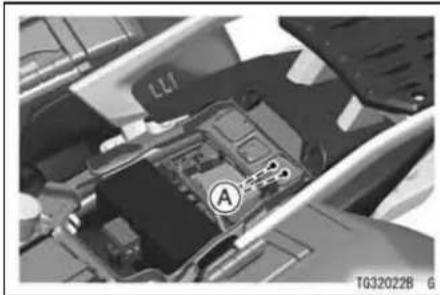
natural_image
Close-up of a mechanical component with labeled parts (A) and part number T032022B, no readable text or symbols beyond labels.A. Connectors (Under Latch)
NOTE
○ When using the electric accessory connectors, the electric accessory connection to the connectors should be done by authorized Kawasaki dealer.
GENERAL INFORMATION
NOTICE
The vehicle has an electrical accessory circuit (5 A fuse) for the socket and connectors. Always install a fuse 5 A or less for the circuit. If this fuse fails, the engine will not stop.
Do not connect more than 60 W of total load to the vehicle's electrical system or the battery may become discharged, even with the engine running.
WARNING
Take care not to pinch any wire between the seat and the frame or between other parts to avoid a short circuit.
112 GENERAL INFORMATION
Brake/Clutch Lever Adjuster
There is an adjuster on both the brake and clutch levers. The brake lever adjuster has 6 positions and the clutch lever adjuster has 5 positions so that the released lever position can be adjusted to suit the operator's hands. Push the lever forward and turn the adjuster to align the number with the triangular mark on brake lever and the triangular mark on the clutch lever. The distance from the grip to the released lever is minimum at Number 6 for the brake lever and Number 5 for the clutch lever, and maximum at Number 1 for both.

A. Adjuster
B. Mark
Fuel Tank Cap
To open the fuel tank cap, pull up the key hole cover. Insert the key knob into the fuel tank cap and turn the key knob to the right.
To close the cap, push it down into place with the key knob inserted. The key knob can be removed by turning it to the left to the original position.
NOTE
○ The fuel tank cap cannot be closed without the key knob inserted, and the key cannot be removed unless the cap is locked properly.
○ Do not push on the key knob to close the cap, or the cap cannot be locked.

natural_image
Close-up of a mechanical component with a circular base and central protrusion (no visible text or symbols)A. Key Hole Cover
B. Key Knob
C. Fuel Tank Cap
114 GENERAL INFORMATION
Fuel Tank
The following octane rating gasoline is recommended in the fuel tank. Avoid filling the tank in the rain or where heavy dust is blowing so that the fuel does not get contaminated.
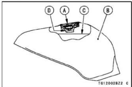
A. Tank Cap
B. Fuel Tank
C. Top Level
D. Filler Neck
WARNING
Gasoline is extremely flammable and can be explosive under certain conditions. Turn the key knob to "FSS". Do not smoke. Make sure the area is well ventilated and free from any source of flame or sparks; this includes any appliance with a pilot light.
Never fill the tank so the fuel level rises into the filler neck. If the tank is overfilled, heat may cause the fuel to expand and overflow through the vents in the tank cap.
After refueling, make sure the fuel tank cap is closed securely. If gasoline is spilled on the fuel tank, wipe it off immediately.
NOTICE
California model only: Never fill the tank so the fuel level rises into the filler neck. If the tank is overfilled, heat may cause the fuel to expand and flow into the Evaporative Emission Control System resulting in hard starting and engine hesitation and in compliance with the emission regulation.
Fuel Requirement
Fuel Type
Use clean, fresh unleaded gasoline with a minimum Antiknock Index of 90.
GENERAL INFORMATION
The Antiknock Index is posted on service station pumps. The octane rating of a gasoline is a measure of its resistance to detonation or "knocking." The Antiknock Index is an average of the Research Octane Number (RON) and the Motor Octane Number (MON) as shown in the table.
| Octane Rating Method | Minimum Rating | |
| Antiknock Index | (RON + MON)2 | 90 |
NOTICE
Use minimum of 90 octane gasoline only to prevent severe engine damage.
NOTICE
If engine "knocking" or "pinging" occurs, use a different brand of gasoline of a higher octane rating. If this condition is allowed to continue it can lead to severe engine damage. Gasoline quality is important. Fuels of low quality or not meeting standard industry specifications may result in unsatisfactory performance. Operating problems that result from the use of poor quality or nonrecommended fuel may not be covered under your warranty.
Fuels Containing Oxygenates
Gasoline frequently contains oxygenates (alcohols and ethers) especially in areas of the U.S. and Canada which are required to sell such reformulated fuels as part of a strategy to reduce exhaust emissions.
The types and volume of fuel oxygenates approved for use in unleaded gasoline by the U.S. Environmental Protection Agency include a broad range of alcohols and ethers, but only two components have seen any significant level of commercial use.
Gasoline/Alcohol Blends - Gasoline containing up to 10% ethanol (alcohol produced from agricultural products such as corn), also known as "gasohol" is approved for use.
NOTICE
Avoid using blends of unleaded gasoline and methanol (wood alcohol) whenever possible, and never use "gasohol" containing more than 5% methanol. Fuel system damage and performance problems may result.
Gasoline/Ether Blends - The most common ether is methyl tertiary butyl ether (MTBE). You may use gasoline containing up to 15% MTBE.
NOTE
○ Other oxygenates approved for use in unleaded gasoline include TAME (up to 16.7 %) and ETBE (up to 17.2 %). Fuel containing these oxygenates can also be used in your Kawasaki.
GENERAL INFORMATION
NOTICE
Never use gasoline with an octane rating lower than the minimum specified by Kawasaki.
Never use "gasohol" with more than 10% ethanol, or more than 5% methanol. Gasoline containing methanol must also be blended with cosolvents and corrosion inhibitors.
Certain ingredients of gasoline may cause paint fading or damage. Be extra careful not to spill gasoline or gasoline oxygenate blends during refueling.
When not operating your Kawasaki for 30 to 60 days, mix a fuel stabilizer (such as STA-BIL) with the gasoline in the fuel tank. Fuel stabilizer additives inhibit oxidation of the fuel which minimizes gummy deposits.
NOTICE
Never store this product with "gasohol" in the fuel system. Before storage it is recommended that you drain all fuel from the fuel system. See the Storage section in this manual.
Stands
The motorcycle is equipped with two stands: a center stand and a side stand.

A. Side Stand
NOTE
○When using the side stand, turn the handlebar to the left.
Whenever the side stand or center stand is used, make it a practice to kick
the stand fully up before sitting on the motorcycle.
NOTE
○ The motorcycle is equipped with a side stand switch. This switch is designed so that the engine does not start if the transmission is in gear and the side stand is down.
GENERAL INFORMATION 119
To set the motorcycle up on the center stand, step down firmly on the stand, and then lift the motorcycle up and to the rear using the grip as a handhold. Don't pull up on the seat to lift as this will damage the seat.
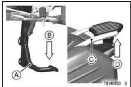
A. Center Stand
B. Step down.
C. Grip
D. Lift up.
120 GENERAL INFORMATION
Seat
Seat Removal
- Remove the seat by inserting the key knob into the seat lock and turning it counterclockwise.
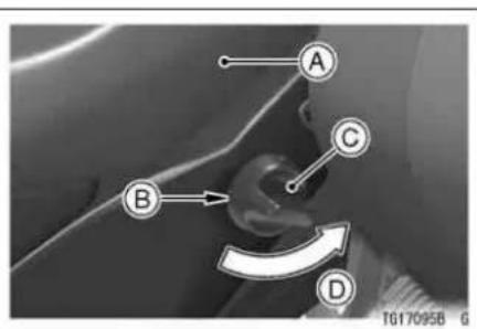
A. Seat
B. Seat Lock
C. Key Knob
D. Turn Counterclockwise
NOTE
○If the seat removal is hard, be sure to insert the key knob fully into the seat lock, then turn the key counterclockwise while strongly pushing down the rear part of the seat.
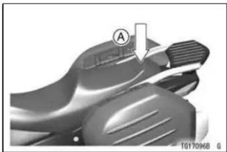
natural_image
Close-up of a mechanical component with a labeled section (A) and arrow indicator, no readable text or symbols beyond the label.A. Push down.
Seat Installation
- Install the seat in the reverse order of removal.
- Place the brackets on each side of the fuel tank into the slots on the front of the seat.

A. Seat
B. Slot
C. Bracket
D. Insert
GENERAL INFORMATION
- Insert the hooks on the middle of the seat into the holders of the frame, and the projection on the rear end of the seat into the slot of the frame.

A. Hooks
B. Holders
C. Projection
D. Slot
E. Insert
- Push down the rear part of the seat until the lock clicks.
122 GENERAL INFORMATION
- Pull up the front and rear end of the seat to make sure they are securely locked.
Special Warning on the Use of Storage Case and Saddlebags (Accessory)
When preparing to ride this motor-cycle, always check the saddlebags for secure mounting in their respective holders. Be certain the saddlebags are securely engaged on their holders and are securely locked by attempting to pull them from the holders. Make sure the saddlebag lids and storage case are securely locked.
WARNING
The sudden detachment or loss of a saddlebag could distract or alarm the motorcycle rider, and the consequent loss of attention to road and traffic conditions could cause loss of control and a serious accident. Also the sudden change of vehicle balance resulting from the loss of a saddlebag could cause loss of control and a serious accident. A dislodged saddlebag could physically obstruct the motorcycle's path, or interfere in the path of a following motorcycle or other vehicle. This could cause a loss of control by one of the motorcycle riders or another vehicle driver with a consequent accident. Be sure the saddlebags are securely fastened to the motorcycle before each ride.
WARNING
Riding with an open saddlebag lid could allow clothing other objects to fall into the rear wheel, resulting in rear wheel lockup and loss of control. Keep both saddlebag covers securely locked when riding.
WARNING
Loose objects can interfere with the steering mechanism, vehicle controls and/or divert the rider's attention from the road and traffic conditions and cause an accident resulting in serious injury or death. Be sure the storage case is tightly closed before riding to prevent any objects stored in it from getting loose. Do not rest, store, or attach objects in the area between the movable parts of the steering mechanism (including handlebar, front fork, etc.) and the fixed parts of the chassis (including fairing, fuel tank, frame etc.)
Saddlebags (Accessory)
The saddlebags are provided at both sides of the rear wheel to carry bag-gage.
To open the saddlebag lid -
- Insert the key knob into the lid lock.
● Turn the key knob to lever side from the lock mark. - Pull up the lever on the top of the saddlebag.
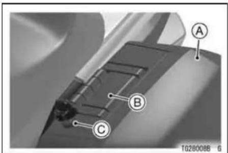
A. Saddlebag
B. Lever
C. Lock
To close the saddlebag lid -
● While holding the lever pulled fully up, push the lid back against the saddlebag all the way.
- Push back the lever to the original position.
- Turn the key knob to the lock mark and pull it out.
● Make sure that the lid is securely locked by pulling the lid and the lever.
126 GENERAL INFORMATION
To remove the saddlebag -
- Insert the key knob into the lid lock.
● Turn the key knob to lever side from the lock mark. - Pull up the handle on the top of the saddlebag.
- Remove the saddlebag by pulling it up.
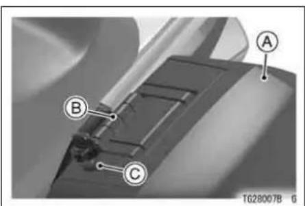
A. Saddlebag
B. Handle
C. Lock
To install the saddlebag -
Distinguish left saddlebag and right saddlebag. See that both saddlebags are set in proper sides. Setting bags in wrong sides could cause breakage of lock mechanism parts or dislodging of bags while riding. Make sure that holder is on the front below of the saddlebag.

natural_image
Close-up of a mechanical component with two labeled parts (A) and an inset view showing internal components (no readable text or symbols)A. Holder
- Hold the handle pulled fully up.
- While aligning the holder on the front below of the saddlebag with the projection on the rear of the passenger footpeg, insert the hooks on the top of the saddlebag into the holders of the under of the seat. See that the hooks are inserted into the end as shown in the figure.
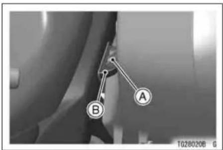
A. Hook
B. Holder
GENERAL INFORMATION
- Push back the handle to the original position.
- Turn the key knob counterclockwise.
- Make sure that the saddlebag and saddlebag lid are securely locked by pulling the handle, the saddlebag, the lid and the lever.

128 GENERAL INFORMATION
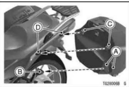
A. Holder
B. Projection
C. Hooks
D. Holders
WARNING
Overloading the motorcycle with cargo and/or passengers, and/or not balancing the weight of items carried in each saddlebag may cause adverse handling, loss of control and an accident resulting in serious injury or death. Do not carry loads of more than 10 kg (22 lb) in each saddlebag. Distribute the load equally on both sides of the motorcycle to minimize imbalance. Do not exceed the total payload limit of 228 kg (503 lb), including rider, passenger, baggage, and accessories. Do not exceed the vehicle speed of 130 km/h (80 mph) when carrying a passenger and/or cargo. Also reduce speed according to road or weather condition, etc. Failure to adjust the speed to compensate for added weight and other conditions may result in a loss of control and subsequent accident.
WARNING
Riding with an open saddlebag lid could allow clothing other objects to fall into the rear wheel, resulting in rear wheel lockup and loss of control. Keep both saddlebag covers securely locked when riding.
NOTICE
Do not sit on the saddlebags and their lids.
Do not put load on the lids.
Storage Case
The storage case is located on the left inner cover.
The compartment is used to store light loads or paper.
- Open the storage case lid by pushing the release button.
- The lid will open automatically.
- Close the storage case lid by pushing down until it clicks.
● Make sure the lid is securely locked by attempting to open it without pushing the release button.

A. Storage Case Lid
B. Release Button
Electric Lock -
This storage case is equipped with an electric lock. When the ignition switch is turned to "OFF" or "FSS", the lid lock is locked automatically. When the ignition switch is turned to "ON", the lid lock is unlocked automatically. Additionally. When speed reaches to 40 km/h (25 mph) or more, the lid lock is locked automatically. And then, when the speed
GENERAL INFORMATION 131
is reached to 3 km/h (2 mph) or less, the lid lock is unlocked automatically.
NOTE
○Remove the FOB from the storage case whenever the ignition switch is turned to "OFF" or "FSS". If the FOB battery is "run down" in the storage case, it is impossible to restart the vehicle.
○ This case is intended for temporary storage during vehicle operation. To avoid theft, do not store valuables in the compartment when leaving the motorcycle.
Do not leave the motorcycle without starting the engine when the ignition switch is turned to "ON". The sole-noid valve of the electric lock repeats "ON/OFF" to prevent the battery from running down.
132 GENERAL INFORMATION
WARNING
Loose objects can interfere with the steering mechanism, vehicle controls and/or divert the rider's attention from the road and traffic conditions and cause an accident resulting in serious injury or death. Be sure the storage case is tightly closed before riding to prevent any objects stored in it from getting loose.
Rear Carrier
This motorcycle is equipped with carriers on the rear.

natural_image
Close-up of a mechanical component with labeled section A, no readable text or symbols presentA. Rear Carrier
WARNING
Overloading the motorcycle with cargo and/or passengers, and/or not balancing the weight of items carried on the rear carrier may cause adverse handling, loss of control and an accident resulting in serious injury or death. Do not carry loads of more than 10 kg (22 lb) on the rear carrier. Do not exceed the total payload limit of 228 kg (503 lb), including rider, passenger, baggage, and accessories. Do not exceed the vehicle speed of 130 km/h (80 mph) when carrying a passenger and/or cargo. Also reduce speed according to road or weather condition, etc. Failure to adjust the speed to compensate for added weight and other conditions may result in a loss of control and subsequent accident.
134 GENERAL INFORMATION
Tool Kit Compartment
The tool kit compartment is located under the seat.
The kit contains tools that can be helpful in making roadside repairs, adjustments, and some maintenance procedures explained in this manual. Keep the tool kit in this case.
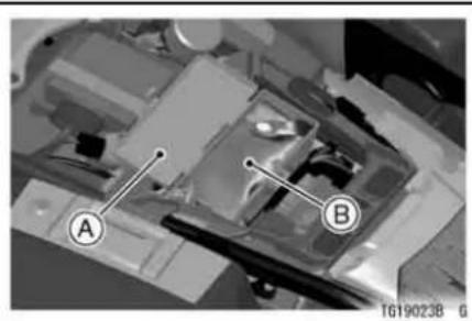
A. Tool Kit Compartment
B. Tool Kit
Air Intake
The air intake allows air to enter the fuel system. Never allow anything to restrict the flow of air into the air intake. A restricted air intake will reduce performance and increase exhaust emissions.

natural_image
Close-up of a motorcycle's head and side panel, highlighting the letter 'A' with an arrow pointing to it (no text or symbols on the main subject)A. Air Intake
BREAK-IN
The first 1 600 km (1 000 miles) that the motorcycle is ridden is designated as the break-in period. If the motorcycle is not used carefully during this period, you may very well end up with a "broken down" instead of a "broken in" motorcycle after a few thousand kilometers.
The following rules should be observed during the break-in period.
- The table shows maximum recommended engine speed during the break-in period.
| Distance traveled | Maximum engine speed |
| 0 ~ 800 km (0 ~ 500 miles) | 4 000 r/min (rpm) |
| 800 ~ 1 600 km (500 ~ 1 000 miles) | 6 000 r/min (rpm) |
- Do not start moving or race the engine immediately after starting it, even if the engine is already warm. Run the engine for two or three minutes at idle speed to give the oil a chance to work up into all the engine parts.
- Do not race the engine while the transmission is in neutral.
136 BREAK-IN
WARNING
New tires are slippery and may cause loss of control and injury. A break-in period of 160 km (100 miles) is necessary to establish normal tire traction. During break-in, avoid sudden and maximum braking and acceleration, and hard cornering.
In addition to the above, at 1 000 km (600 miles) it is extremely important that the owner has the initial maintenance service performed by a competent mechanic following the procedures in the Service Manual.
HOW TO RIDE THE MOTORCYCLE
Starting the Engine
- Check that the engine stop switch is in the position.
- Push down the key knob and release it while carrying the FOB.
- Turn the key knob to "ON" while the symbol of the key knob is displayed for 5 seconds.
NOTE
○ The turn signal light flashes two times when the key knob is pushed in and turned to ON.
- Make sure the transmission is in neutral.

A. Neutral Indicator Light
B. Key Knob
C. ON Position
NOTE
○ The motorcycle is equipped with a vehicle-down sensor, which causes
138 HOW TO RIDE THE MOTORCYCLE

the engine to stop automatically and the warning indicator light to flash when the motorcycle falls down. After righting the motorcycle, first turn the key knob to "OFF" and then back to "ON" before starting the engine.
● After the meter operation check, leaving the throttle completely closed, push the starter button.
NOTICE
Do not operate the starter continuously for more than 5 seconds, or the starter will overheat and the battery power will drop temporarily. Wait 15 seconds between each operation of the starter to let it cool and the battery power recover.
NOTE
The motorcycle is equipped with a starter lockout switch. This switch is designed so that the engine does not start if the transmission is in gear and the side stand is down. However, the engine can be started if the clutch lever is pulled and the side stand is fully up.

natural_image
Close-up mechanical assembly showing components labeled A and B (no readable text or symbols beyond labels)A. Starter Lockout Switch
B. Clutch Lever
NOTICE
Do not let the engine idle longer than five minutes, or engine overheating and damage may occur.
HOW TO RIDE THE MOTORCYCLE 139
Jump Starting
If your motorcycle battery is "run down", it should be removed and charged. If this is not practical, a 12 volt booster battery and jumper cables may be used to start the engine.
DANGER
Battery acid generates hydrogen gas which is flammable and explosive under certain conditions. It is present within a battery at all times, even in a discharged condition. Keep all flames and sparks (cigarettes) away from the battery. Wear eye protection when working with a battery. In the event of battery acid contact with skin, eyes, or clothing, wash the affected areas immediately with water for at least five minutes. Seek medical attention.
Connecting Jumper Cables
- Make sure the key knob is turned to "OFF".
- Remove the sub side cover (see Battery section in the MAINTENANCE AND ADJUSTMENT chapter).
- Connect a jumper cable from the positive (+) terminal of the booster battery to the positive (+) terminal of the motorcycle battery.
NOTICE
Be careful not to contact the jumper cable clip on the positive battery terminal to the frame, or it cause a short circuit.

A. Motorcycle Battery Positive (+) Terminal
B. From Booster Battery Positive (+) Terminal
C. Unpained Metal Surface
D. From Booster Battery Negative (−) Terminal
- Connect another jumper cable from the negative (−) terminal of the booster battery to your motorcycle footpeg or other unpainted metal surface. Do not use the negative (−) terminal of the battery.
HOW TO RIDE THE MOTORCYCLE
DANGER
Batteries contain sulfuric acid that can cause burns and produce hydrogen gas which is highly explosive. Do not make this last connection at the fuel system or battery. Take care not to touch the positive and negative cables together, and do not lean over the battery when making this last connection. Do not connect to a frozen battery. It could explode. Do not reverse polarity by connecting positive (+) to negative (−), or a battery explosion and serious damage to the electrical system may occur.
- Follow the standard engine starting procedure.
142 HOW TO RIDE THE MOTORCYCLE
NOTICE
Do not operate the starter continuously for more than 5 seconds or the starter will overheat and the battery power will drop temporarily. Wait 15 seconds between each operation of the starter to let it cool and the battery power recover.
- After the engine has started, disconnect the jumper cables. Disconnect the negative (−) cable from the motorcycle first.
● Reinstall the removed parts.
Moving Off
- Check that the side stand or center stand is up.
- Pull in the clutch lever.
- Shift into 1st gear.
- Open the throttle a little, and start to let out the clutch lever very slowly.
- As the clutch starts to engage, open the throttle a little more, giving the engine just enough fuel to keep it from stalling.

A. Shift Pedal
NOTE
○ The motorcycle is equipped with a side stand switch. This switch is designed so that the engine does not start if the transmission is in gear and the side stand is down.
HOW TO RIDE THE MOTORCYCLE 143
Shifting Gears
- Close the throttle while pulling in the clutch lever.
- Shift into the next higher or lower gear.
WARNING
Downshifting to a lower gear at high speed causes engine rpm to increase excessively, potentially damaging the engine and it may also cause the rear wheel to skid and cause an accident. Downshifting should be done below 5 000 rpm for each gear.
- Open the throttle part way, while releasing the clutch lever.
- For smooth riding, each gear position should cover the proper rate of speed shown in the table.
144 HOW TO RIDE THE MOTORCYCLE
Vehicle speed when shifting
| Shifting up | km/h (mph) | Shifting down | km/h (mph) |
| 1st → 2nd | 15 (9) | 6th → 5th | 30 (19) |
| 2nd → 3rd | 25 (15) | 5th → 4th | 25 (15) |
| 3rd → 4th | 35 (21) | 4th → 3rd | 20 (12) |
| 4th → 5th | 45 (27) | 3rd → 2nd | 15 (9) |
| 5th → 6th | 55 (34) | 2nd → 1st | 15 (9) |
NOTE
The transmission is equipped with a positive neutral finder. When the motorcycle is standing still, the transmission cannot be shifted past neutral from 1st gear. To use the positive neutral finder, shift down to 1st gear, then lift up on the shift pedal while standing still. The transmission will shift only into neutral.
HOW TO RIDE THE MOTORCYCLE 145
Braking
- Close the throttle completely, leaving the clutch engaged (except when shifting gears) so that the engine will help slow down the motorcycle.
- Shift down one gear at a time so that you are in 1st gear when you come to a complete stop.
- When stopping, always apply both brakes at the same time. Normally the front brake should be applied a little more than the rear. Shift down or fully disengage the clutch as necessary to keep the engine from stalling.
- Never lock the brakes, or it will cause the tires to skid. When turning a corner, it is better not to brake at all. Reduce your speed before you get into the corner.
- Even in motorcycles equipped with K-ACT ABS, braking during cornering
may cause wheel slip. When turning a corner, it is better to limit braking to the light application of both brakes or not to brake at all. Reduce your speed before you get into the corner.
- For emergency braking, disregard downshifting, and concentrate on applying the brakes as hard as possible without skidding.

natural_image
Close-up of a mechanical component with labeled parts (A and P), no readable text or symbols beyond labelsA. Front Brake Lever
146 HOW TO RIDE THE MOTORCYCLE

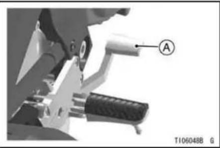
natural_image
Mechanical component with labeled lever and pivot point (no readable text or symbols)A. Rear Brake Pedal
Kawasaki Advanced Coactive-braking Technology (K-ACT) - Anti-lock Brake System (ABS) for models equipped with K-ACT ABS
K-ACT system supports the distribution of the front/rear brake force in an optimum balance to maintain a stable vehicle position. When using the front brake lever, the right and left front calipers and the rear brake operate. When using the rear brake pedal, the rear brake and the right front caliper operate. The cooperative brake balance is controlled optimally in response to the vehicle status such as the brake input and the vehicle speed.
ABS is designed to help prevent the wheels from locking up when the brakes are applied hard while running straight. The ABS automatically regulates brake force. Intermittently gaining gripping force and braking force helps
HOW TO RIDE THE MOTORCYCLE
prevent wheel lock-up and allows stable steering control while stopping.
Although K-ACT system supports the distribution of the front/rear brake force in an optimum balance. The ABS provides stability while stopping by preventing wheel lock-up, remember the following characteristics:
- To apply the brake effectively, use the front brake lever and rear brake pedal simultaneously in the same manner as conventional motorcycle brake system.
- K-ACT ABS cannot compensate for adverse road conditions, misjudgment or improper application of brakes. You must take the same care as with motorcycles not equipped with K-ACT ABS.
- ABS is not designed to shorten the braking distance. On loose, uneven
or downhill surface, the stopping distance of a motorcycle with ABS may be longer than that of equivalent motorcycle without ABS. Use special caution in such areas.
- ABS will help prevent wheel lock-up when braking in a straight line, but it cannot control wheel slip which may be caused by braking during cornering. When turning the corner, it is better to limit breaking to the light application of both brakes or not to brake at all. Reduce your speed before you get into the corner.
- Same as conventional brake system, an excessive sudden braking may cause wheel lock up that makes it harder to control a motorcycle.
- During braking, K-ACT ABS will not prevent the rear wheel lifting.
148 HOW TO RIDE THE MOTORCYCLE
WARNING
K-ACT ABS cannot protect the rider from all possible hazards and is not a substitute for safe riding practices. Be aware of how the K-ACT ABS system operates and its limitations. It is the rider's responsibility to ride at appropriate speeds and manner for weather, road surface and traffic conditions.
- The computers integrated in the K-ACT ABS compares vehicle speed with wheel speed. Since non-recommended tires can affect wheel speed, they may confuse the computers, which can extend braking distance.
WARNING
Use of non-recommended tires cause malfunctioning of K-ACT ABS and can lead to extend braking distance. The rider could have an accident as a result. Always use recommended standard tires for this motorcycle.
NOTE
When K-ACT system is functioning, you may feel a pulsing in the brake lever or pedal and feel a change of the braking touch. When the ABS is functioning, you may feel a pulsing in the brake lever or pedal. These are normal. Maintain braking pressure.
○K-ACT system does not function at the speed of approx. 20 km/h (12 mph) or below when the brake starts to be applied. ABS does not function
at the speed of approx. 5 km/h (3.1 mph) or below.
○ K-ACT ABS does not function if the battery is discharged. When driving with an insufficiently charged battery, K-ACT ABS may not function. Keep the battery in good condition in reference to "Battery maintenance" section.
K-ACT ABS Indicator Light
Normally the K-ACT ABS indicator light goes on when the ignition switch is turned on and goes off shortly after the motorcycle starts moving.
If the K-ACT ABS indicator light shows any of the following, a fault or faults may have taken place in the K-ACT ABS. You should have the K-ACT ABS checked by an authorized Kawasaki dealer.
- The light does not go on when the ignition switch is turned on.
HOW TO RIDE THE MOTORCYCLE 149
- The light remains lit after the motorcycle starts moving.
● The light goes on.
Remember that the K-ACT ABS does not function when the indicator light is on. If the K-ACT ABS fails, the front and rear brakes work normally as a conventional brake system. However, the effectiveness of the brake, especially the rear brake, decreases compared to when K-ACT system functions normally.
NOTE
○K-ACT ABS indicator light may go on under motorcycle riding condition. (ex. The front or rear wheel races.) In this case, first turn the ignition key to "OFF", and then back to "ON". K-ACT ABS indicator lights goes off by this operation, but if K-ACT ABS indicator light remains lit after the motorcycle runs at the speed of approx. 5
150 HOW TO RIDE THE MOTORCYCLE

km/h (3.1 mph) or below, you should have the K-ACT ABS checked by an authorized Kawasaki dealer.
When the K-ACT ABS indicator light is flashing, the K-ACT ABS has been in the low voltage mode (the battery voltage decreases). When it is in the low voltage mode, the K-ACT system does not function, but the ABS functions. The ignition switch is turned off to recover the K-ACT system. At this time, the battery must be in the normal condition. If the low voltage mode continues, you should have the K-ACT ABS checked by an authorized Kawasaki dealer.
Stopping the Engine
- Close the throttle completely.
- Shift the transmission into neutral.
- Turn the key knob to "OFF".
NOTE
When turning the key knob to "OFF" or "FSS" position, the turn signal light flashes one time and the symbol of the knob key is displayed in the multifunction meter for 5 seconds. Refer to the Ignition Switch section of the "General Information" chapter for the detailed information of ignition switch.
● Support the motorcycle on a firm, level surface with the side stand.
- Lock the steering.
NOTE
○The motorcycle is equipped with a vehicle-down sensor, which causes
HOW TO RIDE THE MOTORCYCLE 151
the engine to stop automatically and the warning light to flash when the motorcycle falls down. After righting the motorcycle, first turn the key knob to "OFF" and then back to "ON" before starting the engine.
Stopping the Motorcycle in an Emergency
Your Kawasaki Motorcycle has been designed and manufactured to provide you optimum safety and convenience. However, in order to fully benefit from Kawasaki's safety engineering and craftsmanship, it is essential that you, the owner and operator, properly maintain your motorcycle and become thoroughly familiar with its operation. Improper maintenance can create a dangerous situation known as throttle failure. Two of the most common causes of throttle failure are:
- An improperly serviced or clogged air cleaner may allow dirt and dust to enter the throttle body and stick the throttle open.
- During removal of the air cleaner, dirt is allowed to enter and jam the fuel injection system.
152 HOW TO RIDE THE MOTORCYCLE
In an emergency situation such as throttle failure, your vehicle may be stopped by applying the brakes and disengaging the clutch. Once this stopping procedure is initiated, the engine stop switch may be used to stop the engine. If the engine stop switch is used, turn off the ignition switch after stopping the motorcycle.
Parking
- Shift the transmission into neutral and turn the key knob to "OFF".
● Support the motorcycle on a firm, level surface with the side stand.
NOTICE
Do not park on a soft or steeply inclined surface, or the motorcycle may fall over.
- If parking inside a garage or other structure, be sure it is well ventilated and the motorcycle is not close to any source of flame or sparks; this includes any appliance with a pilot light.
WARNING
The muffler and exhaust pipe are very hot while the engine is running and just after the engine stops. This can ignite a fire, resulting in property damage or severe personal injury. Do not idle or park your vehicle in an area where flammable materials such as grasses or dry leaves may come in with the muffler or exhaust pipe.
WARNING
Gasoline is extremely flammable and can be explosive under certain conditions, creating the potential for serious burns. Turn the ignition switch to "OFF". Do not smoke. Make sure the area is well-ventilated and free from any source of flame or sparks; this includes any appliance with a pilot light. Never fill the tank completely to the top. If the tank is filled completely to the top, heat may cause the fuel to expand and overflow through the vents in the tank cap. After refueling, make sure the tank cap is closed securely. If gasoline is spilled on the fuel tank, wipe it off immediately.
154 HOW TO RIDE THE MOTORCYCLE
- Lock the steering to help prevent theft.
Catalytic Converter
This motorcycle is equipped with a catalytic converter in the exhaust system. Platinum and rhodium in the converter react with carbon monoxide, hydrocarbons and nitrogen oxides to convert them into carbon dioxide, water, nitrogen and oxygen resulting in much cleaner exhaust gases to be discharged into the atmosphere.
For proper operation of the catalytic converter, the following cautions must be observed.
WARNING
The muffler and exhaust pipe are very hot while the engine is running and just after the engine stops. This can ignite a fire, resulting in property damage or severe personal injury. Do not idle or park your vehicle in an area where flammable materials such as grasses or dry leaves may come in with the muffler or exhaust pipe.
- Use only unleaded gasoline. Never use leaded gasoline. Leaded gasoline significantly reduces the capability of the catalytic converter.
- Do not operate the vehicle with the engine or any one cylinder misfiring. Under these conditions unburned
HOW TO RIDE THE MOTORCYCLE 155
air/fuel mixture flowing out of engine excessively accelerates reaction in the converter allowing the converter to overheat and become damaged when the engine is hot, or reduces converter performance when the engine is cold.
156 HOW TO RIDE THE MOTORCYCLE
Kawasaki TRaction Control (KTRC) for models equipped with KTRC
The KTRC calculates the slip level of the rear wheel and may adjust engine output automatically. The KTRC is designed to function on public roads. Acceleration may be delayed under certain circumstances depending on road conditions. The KTRC cannot respond to every condition.
WARNING
KTRC cannot protect the rider from all possible hazards and is not a substitute for safe riding practices. All riders must be aware of how the KTRC system operates and its limitations. It is still your responsibility to ride at appropriate speeds and throttle control for weather, road surface and traffic conditions.
Some conditions may cause the KTRC to automatically turn off. The function can be activated again by turning the ignition key of the OFF position, then turning the ignition to the ON position and running the motorcycle at more than 5 km/h (3.1 mph). Always verify the KTRC function is in the desired position by checking the KTRC indicator light.
WARNING
On a slippery road surface, never suddenly fully release the throttle grip without the clutch disengaged. Using the clutch rather than the throttle to control engine output on a slippery road could cause the engine to stall. Always use recommended standard tires for this motorcycle. Use of non-recommended tires could cause malfunctioning or improper operation of KTRC.
When getting out of a slippery road while the KTRC is operating, close the throttle first, and then open it again.
HOW TO RIDE THE MOTORCYCLE 157
KTRC Indicator Light
Operation -
The KTRC indicator light in the tachometer and the multifunction meter show the operating condition of the KTRC.
The KTRC indicator light is displayed when the KTRC function is turned off.
While the KTRC is operating, the KTRC indicator light flashes quickly and the message "KTRC WORKING" is displayed in the multifunction meter.
158 HOW TO RIDE THE MOTORCYCLE


A. KTRC Indicator Light
B. Multifunction Meter
C. "KTRC WORKING" Message
NOTE
When the rider purposely operates the KTRC for extended time periods, the message "KTRC SLOW DOWN" is displayed in the multifunction meter and the engine output is further restricted. When this occurs, release the throttle grip until the KTRC indicator light stops flashing. Keeping the
throttle opened in spite of the warning could cause motorcycle failure.

A. KTRC Indicator Light
B. Multifunction Meter
C. "KTRC SLOW DOWN" Message
Self-diagnosis Uncompleted -
When the KTRC self-diagnosis has not been completed, the KTRC indicator light flashes slowly. The KTRC function cannot be used until the self-diagnosis has been completed. To
HOW TO RIDE THE MOTORCYCLE 159
complete the self-diagnosis, start the engine and run the motorcycle at a speed above 5 km/h (3.1 mph). When completing the self-diagnosis, start the motorcycle carefully since the KTRC does not function until the proper speed is reached.
KTRC Malfunction -
When failure occurs in the KTRC system, the KTRC indicator light goes on automatically, and at the same time the warning indicator light or the K-ACT ABS indicator light goes on. Also, the warning message "KTRC ERROR" is displayed in the multifunction meter. If the indicator light goes on, and warning messages are displayed, the KTRC stops functioning.
NOTE
○In unusual running conditions, the KTRC may detect abnormality, and the KTRC indicator light goes on.
Turn the ignition switch to "OFF", and then back to "ON". The KTRC indicator light goes off by this operation, but if KTRC indicator light remains lit after the motorcycle runs at the speed of 5 km/h (3.1 mph) or below, you should have the KTRC checked by an authorized Kawasaki dealer.
Remember that the KTRC does not function when the KTRC indicator light goes on, but if the KTRC fails, the conventional riding still works normally.
160 HOW TO RIDE THE MOTORCYCLE

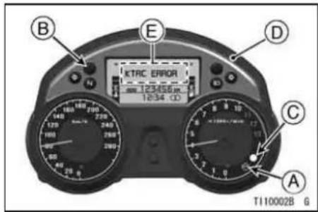
A. KTRC Indicator Light
B. Warning Indicator Light
C. K-ACT ABS Indicator Light
D. Multifunction Meter
E. Warning Message "KTRC ERROR"
KTRC Button
This button is used for selecting the operation of KTRC.

natural_image
Close-up of a camera control interface with no visible text or symbols on the device itselfA. KTRC Button
To set the KTRC -
- Depress the KTRC button on the left handlebar for more than one second but less than three seconds to switch the KTRC function on and off.
- When the KTRC function is off, the KTRC indicator light goes on.
- When the KTRC function is on, the KTRC indicator light goes off or flashes slowly.
- The KTRC function is switched on and off once the button is released.
NOTE
○Depressing the KTRC button for more than three seconds will not affect the KTRC mode. After operating the KTRC button, check the KTRC indicator light to verify that the KTRC
HOW TO RIDE THE MOTORCYCLE 161
function has been switched to the desired position.
○ When the motorcycle is off, turning the ignition key to the ON position automatically engages, the KTRC function.
○ The KTRC function cannot be turned off when the KTRC indicator light flashes quickly.

Safe Riding Technique
The points given below are applicable for everyday motorcycle use and should be carefully observed for safe and effective vehicle operation.
For safety, eye protection and a helmet are strongly recommended. You should be aware of and verify the applicable safety regulations in force prior to riding your motorcycle. Gloves and suitable footwear should also be used for added protection in case of a mishap.
A motorcycle does not provide the impact protection of an automobile, so defensive riding in addition to wearing protective apparel is extremely important. Do not let protective apparel give you a false sense of security.
When riding always keep both hands on the handlebars and both feet on the footpegs. Removing your hands from the handlebars or feet from the footpegs while riding can be hazardous. If you remove even one hand or foot, you can reduce your ability to control the motorcycle.
Before changing lanes, look over your shoulder to make sure the way is clear. Do not rely solely on the rear view mirror; you may misjudge a vehicle's distance and speed, or you may not see it at all.
In general your actions should be smooth as sudden acceleration, braking or turning may cause loss of control, especially when riding in wet conditions or on loose roadway surfaces, when the ability to maneuver will be reduced.
When going up steep slopes, shift to a lower gear so that there is plenty of power to spare rather than overloading the engine.
When applying the brakes, use both the front and rear brakes. Applying only one brake for sudden braking may cause the motorcycle to skid and lose control.
When going down long slopes, control vehicle speed by closing the throttle. Use the front and rear brakes for auxiliary braking.
In wet conditions, rely more on the throttle to control vehicle speed and less on the front and rear brakes. The throttle should also be used judiciously to avoid skidding the rear wheel from too rapid acceleration or deceleration.
Riding at the proper rate of speed and avoiding unnecessarily fast acceleration are important not only for safety and low fuel consumption but also for long vehicle life and quieter operation.
On rough roads, exercise caution, slow down, and grip the fuel tank with the knees for better stability.
When quick acceleration is necessary as in passing, shift to a lower gear to obtain the necessary power.
164 SAFE OPERATION
Do not downshift at too high an r/min (rpm) to avoid damage to the engine from overrevving.
Avoiding unnecessary weaving is important to the safety of both the rider and other motorists.
Daily Safety Checks
Check the following items each day before you ride. The time required is minimal, and habitual performance of these checks will help ensure you a safe, reliable ride.
If any irregularities are found during these checks, refer to the Maintenance and Adjustment chapter or see your dealer for the action required to return the motor-cycle to a safe operating condition.
WARNING
Failure to perform these checks before operation may result in serious damage or an accident. Always perform daily safety checks before operation.
DANGER
Exhaust gas contains carbon monoxide, a colorless, odorless poisonous gas.
Inhaling carbon monoxide can cause serious brain injury or death.
Do not run the engine in enclosed areas. Operate only in a well-ventilated area.
Fuel ...... Adequate supply in tank, no leaks.
Engine Oil .... Oil level between level lines.
166 SAFE OPERATION
Tires ...... Air pressure (when cold):
| Front | 290 kPa (2.90 kgf/cm ^2 , 42 psi) |
| Rear | 290 kPa (2.90 kgf/cm ^2 , 42 psi) |
Install the air valve cap.
Nuts, Bolts, Fasteners Check that steering and suspension components, axles, and all controls are properly tightened or fastened.
Steering .... Action smooth but not loose from lock to lock. No binding of control cables.
Brakes .... Brake pad wear: Lining thickness more than 1 mm (0.04 in.) left.
No brake fluid leakage.
Throttle ...... Throttle grip play 2 \~ 3 mm (0.08 \~ 0.12 in.).
Clutch No clutch fluid leakage.
Coolant .... No coolant leakage.
Coolant level between level lines (when engine is cold).
Final Gear Case ...... No oil leakage.
Electrical Equipment ... All lights (Head, Tail/Brake, Turn Signal, License Plate, Warning/Indicator) and horn work.
Engine Stop Switch .... Stops engine.
Side Stand and Center
Stand ...... Return to its fully up position by spring tension.
Return spring not weak or not damaged.
Refer to the "Daily Safety Checks" caution label attached to the lid of the tool kit case.
168 SAFE OPERATION
Additional Considerations for High Speed Operation
Brakes: The importance of the brakes, especially during high speed operation, cannot be overemphasized. Check to see that they are correctly adjusted and functioning properly.
Steering: Looseness in the steering can cause loss of control. Check to see that the handlebar turns freely but has no play.
Tires: High speed operation is hard on tires, and good tires are crucial for riding safety. Examine their overall condition, inflate them to the proper pressure, and check the wheel balance.
Fuel: Have sufficient fuel for the high fuel consumption during high speed operation.
Engine Oil: To avoid engine seizure and resulting loss of control, make sure that the oil level is at the upper level line.
Coolant: To avoid overheating, check that the coolant level is at the upper level line.
Final Gear Case Oil: To avoid gear seizure and resulting loss of control, make sure the oil level is correct.
Electrical Equipment: Make sure that the headlight, tail/brake light, turn signal lights, license plate light, horn, etc., all work properly.
Miscellaneous: Make sure that all nuts and bolts are tight and that all safety related parts are in good condition.
WARNING
Handling characteristics of a motorcycle at high speeds may vary from those you are familiar with at legal highway speeds. Do not attempt high speed operation unless you have received sufficient training and have the required skills.
170 MAINTENANCE AND ADJUSTMENT
MAINTENANCE AND ADJUSTMENT
The maintenance and adjustments outlined in this chapter must be carried out in accordance with the Periodic Maintenance Chart to keep the motorcycle in good running condition. The initial maintenance is vitally important and must not be neglected.
With a basic knowledge of mechanics and the proper use of tools, you should be able to carry out many of the maintenance items described in this chapter. If you lack proper experience or doubt your ability, all adjustments, maintenance, and repair work should be completed by a qualified technician.
Please note that Kawasaki cannot assume any responsibility for damage resulting from incorrect or improper adjustment made by the owner.
EMISSION CONTROL INFORMATION
To protect the environment in which we all live, Kawasaki has incorporated crankcase emission (1) and exhaust emission (2) control systems in compliance with applicable regulations of the United States Environmental Protection Agency and California Air Resources Board. Additionally, Kawasaki has incorporated an evaporative emission control system (3) in compliance with applicable regulations of the United States Environmental Protection Agency.
1. Crankcase Emission Control System
This system eliminates the release of crankcase vapors into the atmosphere. Instead, the vapors are routed through an oil separator to the intake side of the engine. While the engine is operating, the vapors are drawn into the combustion chamber, where they are burned along with the fuel and air supplied by the fuel injection system.
2. Exhaust Emission Control System
This system reduces the amount of pollutants discharged into the atmosphere by the exhaust of this motorcycle. The fuel, ignition and exhaust systems of this motorcycle have been carefully designed and constructed to ensure an efficient engine with low exhaust pollutant levels. The exhaust system of this model motorcycle includes a catalytic converter system.
172 MAINTENANCE AND ADJUSTMENT
3. Evaporative Emission Control System
The evaporative emission control system for this vehicle consists of low permeation fuel hoses and fuel tank.
3. Evaporative Emission Control System (California)
Vapors caused by fuel evaporation in the fuel system are not vented into the atmosphere. Instead, fuel vapors are routed into the running engine to be burned, or stored in a canister when the engine is stopped. Liquid fuel is caught by a vapor separator and returned to the fuel tank.
High Altitude Performance Adjustment Information
High altitude adjustment is not required.
MAINTENANCE AND WARRANTY
Proper maintenance is necessary to ensure that your motorcycle will continue to have low emission levels. This Owner's Manual contains those maintenance recommendations for your motorcycle. Those items identified by the Periodic Maintenance Chart are necessary to ensure compliance with the applicable standards.
As the owner of this motorcycle, you have the responsibility to make sure that the recommended maintenance is carried out according to the instructions in this Owner's Manual at your own expense.
The Kawasaki Limited Emission Control System Warranty requires that you return your motorcycle to an authorized Kawasaki dealer for remedy under warranty. Please read the warranty carefully, and keep it valid by complying with the owner's obligations it contains.
You should keep a maintenance record for your motorcycle. To assist you in keeping this record, we have provided space on pages 265 through 268 of this manual where an authorized Kawasaki dealer, or someone equally competent, can record the maintenance. You should also retain copies of maintenance work orders, bills, etc., as verification of this maintenance.
174 MAINTENANCE AND ADJUSTMENT
TAMPERING WITH NOISE CONTROL SYSTEM PROHIBITED:
Federal law prohibits the following acts or the causing thereof: (1) the removal or rendering inoperative by any person other than for purposes of maintenance, repair, or replacement, of any device or element of design incorporated into any new vehicle for the purpose of noise control prior to its sale or delivery to the ultimate purchaser or while it is in use, or (2) the use of the vehicle after such device or element of design has been removed or rendered inoperative by any person.
Among those acts presumed to constitute tampering are the acts listed below:
* Replacement of the original exhaust system or muffler with a component not in compliance with Federal regulations.
* Removal of the muffler(s) or any internal portion of the muffler(s).
* Removal of the air box or air box cover.
* Modifications to the muffler(s) or air intake system by cutting, drilling, or other means if such modifications result in increased noise levels.
Periodic Maintenance Chart
- Periodic Inspection (Engine Related Items)
| FrequencyOperation(Engine Items) | Whichever comes first↓ Every | *Odometer Readingkm × 1 000 (mile × 1 000) | SeePage | ||||||
| 1(0.6) | 6(3.75) | 12(7.5) | 18(11.25) | 24(15) | 30(18.75) | 36(22.5) | |||
| Valve clearance- inspect | ● | 202 | |||||||
| Throttle control system (play, smooth return, no drag) - inspect | year | ● | ● | ● | ● | 211 | |||
| Engine vacuum synchronization - inspect | ● | ● | ● | 213 | |||||
| Idle speed - inspect | ● | ● | ● | ● | 214 | ||||
176 MAINTENANCE AND ADJUSTMENT
| FrequencyOperation(Engine Items) | Whichever comes first↓ Every | *Odometer Readingkm × 1 000 (mile × 1 000) | SeePage | ||||||
| 1(0.6) | 6(3.75) | 12(7.5) | 18(11.25) | 24(15) | 30(18.75) | 36(22.5) | |||
| K Fuel leak (fuel hose and pipe) - inspect | year | ● | ● | ● | ● | - | |||
| K Fuel hoses damage - inspect | year | ● | ● | ● | ● | - | |||
| K Fuel hoses installation condition - inspect | year | ● | ● | ● | ● | - | |||
| Coolant level - inspect | ● | ● | ● | ● | 198 | ||||
| Coolant leak - inspect | year | ● | ● | ● | ● | 196 | |||

| FrequencyOperation(Engine Items) | Whichever comes first↓ Every | *Odometer Readingkm × 1 000 (mile × 1 000) | SeePage | ||||||
| 1(0.6) | 6(3.75) | 12(7.5) | 18(11.25) | 24(15) | 30(18.75) | 36(22.5) | |||
| Radiator hose damage - inspect | year | ● | ● | ● | ● | 196 | |||
| Radiator hoses installation condition - inspect | year | ● | ● | ● | ● | 196 | |||
| Evaporative emission control system - function (California model only) | ● | ● | ● | ● | ● | ● | ● | 201 | |
| Air suction system damage - inspect | ● | ● | ● | 203 | |||||
178 MAINTENANCE AND ADJUSTMENT
- Periodic Inspection (Chassis Related Items)
| FrequencyOperation(ChassisItems) | Whichevercomes first↓ Every | *Odometer Readingkm × 1 000 (mile × 1 000) | SeePage | ||||||
| 1(0.6) | 6(3.75) | 12(7.5) | 18(11.25) | 24(15) | 30(18.75) | 36(22.5) | |||
| Clutch and drive train: | |||||||||
| Clutchoperation (play,engagement,disengagement)- inspect | ● | ● | ● | ● | 215 | ||||
| Clutch fluid level- inspect | 6 months | ● | ● | ● | ● | ● | ● | ● | 215 |
| Clutch fluid leak- inspect | year | ● | ● | ● | ● | ● | ● | ● | - |
| Clutch hosedamage -inspect | year | ● | ● | ● | ● | ● | ● | ● | - |

| FrequencyOperation(ChassisItems) | Whichevercomes first↓ Every | *Odometer Readingkm × 1 000 (mile × 1 000) | SeePage | ||||||
| 1(0.6) | 6(3.75) | 12(7.5) | 18(11.25) | 24(15) | 30(18.75) | 36(22.5) | |||
| Clutch hoseinstallationcondition -inspect | year | ● | ● | ● | ● | ● | ● | ● | - |
| Final gear caseoil level - inspect# | ● | ● | ● | 192 | |||||
| Wheels and tires: | |||||||||
| Tire air pressure- inspect | year | ● | ● | ● | 230 | ||||
| Wheels/tiresdamage -inspect | ● | ● | ● | 231 | |||||
180 MAINTENANCE AND ADJUSTMENT
| FrequencyOperation(ChassisItems) | Whichevercomes first↓ Every | *Odometer Readingkm × 1 000 (mile × 1 000) | SeePage | ||||||
| 1(0.6) | 6(3.75) | 12(7.5) | 18(11.25) | 24(15) | 30(18.75) | 36(22.5) | |||
| Tire tread wear,abnormal wear -inspect | ● | ● | ● | 231 | |||||
| Wheel bearingsK damage -inspect | year | ● | ● | ● | - | ||||
| Brake system: | |||||||||
| Brake fluid leak- inspect | year | ● | ● | ● | ● | ● | ● | ● | 217 |
| Brake hosesand pipedamage -inspect | year | ● | ● | ● | ● | ● | ● | ● | 217 |
| Brake pad wear- inspect # | ● | ● | ● | ● | ● | ● | 217 | ||

| FrequencyOperation(ChassisItems) | Whichevercomes first↓ Every | *Odometer Readingkm × 1 000 (mile × 1 000) | SeePage | ||||||
| 1(0.6) | 6(3.75) | 12(7.5) | 18(11.25) | 24(15) | 30(18.75) | 36(22.5) | |||
| Brake hoseinstallationcondition -inspect | year | ● | ● | ● | ● | ● | ● | ● | 217 |
| Brake fluid level- inspect | 6 months | ● | ● | ● | ● | ● | ● | ● | 217 |
| Brake operation(effectiveness,play, drag) -inspect | year | ● | ● | ● | ● | ● | ● | ● | 220 |
| Brake lightswitch operation- inspect | ● | ● | ● | ● | ● | ● | ● | 220 | |
182 MAINTENANCE AND ADJUSTMENT
| FrequencyOperation(ChassisItems) | Whichevercomes first↓ Every | *Odometer Readingkm × 1 000 (mile × 1 000) | SeePage | ||||||
| 1(0.6) | 6(3.75) | 12(7.5) | 18(11.25) | 24(15) | 30(18.75) | 36(22.5) | |||
| Suspensions: | |||||||||
| Front forks/rearshock absorberoperation(damping andsmooth stroke) -inspect | ● | ● | ● | 222/226 | |||||
| Front forks/rearshock absorberoil leak - inspect | year | ● | ● | ● | 222/226 | ||||
| Uni-trak rockerK arm operation -inspect | ● | ● | ● | - | |||||
| Uni-trak tieK rods operation -inspect | ● | ● | ● | - | |||||
| Steering system: | |||||||||
| K Steering play -inspect | year | ● | ● | ● | ● | - | |||
| K Steering stembearings -lubricate | 2 years | ● | - | ||||||
| Electrical system: | |||||||||
| Lights andswitchesoperation -inspect | year | ● | ● | ● | - | ||||
184 MAINTENANCE AND ADJUSTMENT
| FrequencyOperation(ChassisItems) | Whichevercomes first↓ Every | *Odometer Readingkm × 1 000 (mile × 1 000) | SeePage | ||||||
| 1(0.6) | 6(3.75) | 12(7.5) | 18(11.25) | 24(15) | 30(18.75) | 36(22.5) | |||
| Headlightaiming - inspect | year | ● | ● | ● | 243 | ||||
| Side standswitch operation- inspect | year | ● | ● | ● | - | ||||
| Engine stopswitch operation- inspect | year | ● | ● | ● | - | ||||
| Chassis: | |||||||||
| Chassis parts -lubricate | year | ● | ● | ● | 247 | ||||
| Bolts and nutstightness -inspect | ● | ● | ● | ● | 254 | ||||
- Periodic Replacement
| FrequencyChange/Replacement Items | Whichever comes first↓Every | *Odometer Readingkm × 1 000 (mile × 1 000) | SeePage | ||||
| 1(0.6) | 12(7.5) | 24(15) | 36(22.5) | 48(30) | |||
| Air cleaner element # - replace | every 18 000 km (11 250 mile) | 204 | |||||
| K Engine oil # - change | year | ● | ● | ● | ● | ● | 189 |
| K Oil filter - replace | year | ● | ● | ● | ● | ● | 189 |
| K Fuel hoses - replace | 4 years | ● | - | ||||
| K Coolant - change | 3 years | ● | 200 | ||||
| K Radiator hoses and O-rings - replace | 3 years | ● | - | ||||
| K Brake or clutch hoses - replace | 4 years | ● | - | ||||
| K Brake or clutch fluid (front and rear) - change | 2 years | ● | ● | 215/219 | |||
186 MAINTENANCE AND ADJUSTMENT
| FrequencyChange/Replacement Items | Whichever comes first↓Every | *Odometer Readingkm × 1 000 (mile × 1 000) | SeePage | ||||
| 1(0.6) | 12(7.5) | 24(15) | 36(22.5) | 48(30) | |||
| Rubber parts of masterK cylinder and caliper (or slave cylinder) - replace | 4 years | ● | - | ||||
| Spark plug - replace | ● | ● | ● | ● | 200 | ||
| Final gear case oil - change | ● | ● | ● | ● | ● | 193 | |
K: Should be serviced by an authorized Kawasaki dealer.
*: For higher odometer readings, repeat at the frequency interval established here.
: Service more frequently when operating in severe conditions: dusty, wet, muddy, high speed, or frequent starting/stopping.
Engine Oil
In order for the engine, transmission, and clutch to function properly, maintain the engine oil at the proper level, and change the oil and replace the oil filter in accordance with the Periodic Maintenance Chart. Not only do dirt and metal particles collect in the oil, but the oil itself loses its lubricative quality if used too long.
WARNING
Motorcycle operation with insufficient, deteriorated, or contaminated engine oil will cause accelerated wear and may result in engine or transmission seizure, accident, and injury. Check the oil level before each ride and change the oil according to the periodic maintenance chart in the Owner's Manual.
MAINTENANCE AND ADJUSTMENT
Oil Level Inspection
- If the oil has just been changed, start the engine and run it for several minutes at idle speed. This fills the oil filter with oil. Stop the engine, then wait several minutes until the oil settles.
NOTICE
Racing the engine before the oil reaches every part can cause engine seizure.
- If the motorcycle has just been used, wait several minutes for all the oil to drain down.
- Check the engine oil level through the oil level gauge. With the motorcycle held level, the oil level should come up between the upper and lower level lines next to the gauge.
188 MAINTENANCE AND ADJUSTMENT
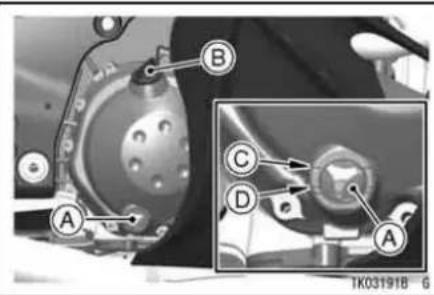
A. Oil Level Gauge
B. Oil Filler Cap
C. Upper Level Line
D. Lower Level Line
- If the oil level is too high, remove the excess oil through the oil filler opening using a syringe or some other suitable device.
- If the oil level is too low, add oil to reach the correct level. Use the same type and brand of oil that is already in the engine.
NOTICE
If the engine oil gets extremely low or if the oil pump does not function properly or oil passages are clogged, the oil pressure warning indicator light will go on. If it stays on when the engine speed is above idle, stop the engine immediately and have it serviced. Failure to do so could cause serious engine damage.
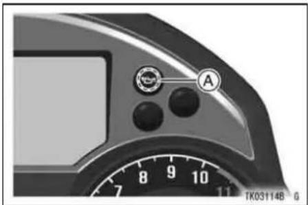
natural_image
Close-up of a camera face with adjustment knobs and a dial (no readable text or symbols)A. Oil Pressure Warning Indicator Light
Oil and/or Oil Filter Change
- To change the engine oil and replace oil filter, the engine oil drain bolt and oil filter must be removed. The oil
MAINTENANCE AND ADJUSTMENT 189
change and oil filter replacement should be done by an authorized Kawasaki dealer.
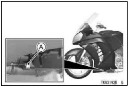
natural_image
Side-by-side comparison of a motorcycle's front view and its side profile, showing front wheel and rear wheel (no text or symbols)A. Engine Oil Drain Bolt
190 MAINTENANCE AND ADJUSTMENT

natural_image
Mechanical assembly diagram showing a motor component with labeled section A, alongside a close-up of the motor wheel (no text or symbols on the diagram itself)A. Oil Filter
WARNING
Motor oil is a toxic substance. Dispose of used oil properly. Contact your local authorities for approved disposal methods or possible recycling.
Tightening Torque
Engine Oil Drain Bolt:
30 N·m (3.1 kgf·m, 22 ft·lb)
Oil Filter:
17 N·m (1.7 kgf·m, 13 ft·lb)
Recommended Engine Oil
Type:
API SG, SH, SJ, SL or SM with JASO
MA, MA1 or MA2
Viscosity:
SAE 10W-40
Engine Oil Capacity
Capacity:
4.0 L (4.2 US qt) (when filter is not removed)
4.4 L (4.7 US qt) (when filter is removed)
4.7 L (5.0 US qt) (when engine is completely dry)
NOTE
○Do not add any chemical additive to the oil. Oils fulfilling the above requirements are fully formulated and provide adequate lubrication for both the engine and the clutch.
Although 10W-40 engine oil is the recommended oil for most conditions, the oil viscosity may need to be changed to accommodate atmospheric conditions in your riding area.

bar
| Category | Value (°C) | |---|---| | SAE 20W-50 | 40 | | SAE 20W-40 | 30 | | SAE 10W-50 | 30 | | SAE 10W-40 | 20 | | SAE 10W-30 | 10 |192 MAINTENANCE AND ADJUSTMENT
Final Gear Case Oil
In order for the pinion and ring gears in the final gear case to function properly, check the oil level, and change the oil in accordance with the Periodic Maintenance Chart.
WARNING
Motorcycle operation with insufficient, deteriorated, or contaminated oil causes accelerated wear of the differential, pinion, and ring gears and may result in seizure. Seizure can lock the rear wheel and skid the rear tire, with consequent loss of control. Check the differential oil according to the periodic maintenance chart.
Oil Level Inspection
- Use the center stand by holding the motorcycle vertical on level ground.
- Remove the filler cap.
NOTICE
Be careful not to allow any dirt or foreign materials to enter the gear case.
- Check the oil level. If it is low, add oil as necessary. The oil level should come to the top thread of the filler opening with the motorcycle held vertical on level ground.
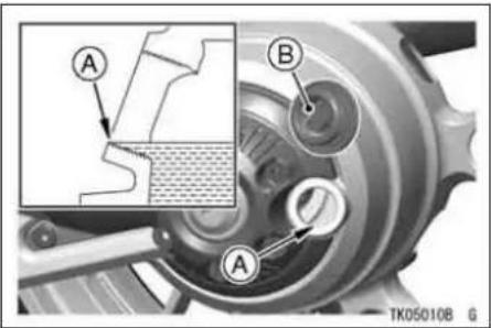
A. Top Thread B. Filler Cap
NOTE
○ Use the same type and brand of oil that is already in the final gear case.
MAINTENANCE AND ADJUSTMENT 193
Oil Change
NOTE
○Final gear case oil drains easily and picks up any sediment when the oil is warmed up by running the motorcycle.
- Put the motorcycle on its side stand.
- Place an oil pan beneath the gear case.
- Remove the filler cap and drain bolt.
WARNING
Gear case oil is a toxic substance. Dispose of used oil properly. Contact your local authorities for approved disposal methods or possible recycling.
194 MAINTENANCE AND ADJUSTMENT

natural_image
Mechanical assembly diagram showing a belt drive mechanism with labeled components A and B (no text or symbols beyond labels)A. Drain Bolt
B. Oil Filler Cap
WARNING
Oil on tires can make them slippery which can cause an accident and injury. When draining or filling the gear case, be careful that no oil gets on the tires or rims. Clean off any oil that inadvertently gets on them with soap and water.
● After the oil has completely drained out, install the drain bolt and a new gasket.
- With the motorcycle held vertical on level ground, fill the gear case up to the top thread of the filler opening with the oil specified below without turning the rear tire.
- If the rear tire is turned, it is necessary to leave it for about six minutes.
Final Gear Case Oil
| Oil Capacity | about 160 mL (5.41 US oz.) |
| Oil Type | API “GL-5”Hypoid gear oilabove 5°C (41°F) SAE 90below 5°C (41°F) SAE 80 |
NOTE
"GL-5" indicates a quality and additive rating. "GL-6" rated hypoid gear oils can also be used.
MAINTENANCE AND ADJUSTMENT 195
- Install the filler cap.
Cooling System
Radiator and Cooling Fan -
Check the radiator fins for obstruction by insects or mud. Clean off any obstructions with a stream of low-pressure water.
WARNING
The cooling fan spins at high speed and can cause serious injuries. Keep your hands and clothing away from the cooling fan blades at all times.
196 MAINTENANCE AND ADJUSTMENT
NOTICE
Using high-pressure water, as from a car wash facility, could damage the radiator fins and impair the radiator's effectiveness. Do not obstruct or deflect airflow through the radiator by installing unauthorized accessories in front of the radiator or behind the cooling fan. Interference with the radiator airflow can lead to overheating and consequent engine damage.
Radiator Hoses -
Check the radiator hoses for leakage, cracks or deterioration, and connections for leakage, or looseness each day before riding the motorcycle, and in accordance with the Periodic Maintenance Chart.
Coolant -
Coolant absorbs excessive heat from the engine and transfers it to the air at the radiator. If the coolant level becomes low, the engine overheats and may suffer severe damage. Check the coolant level each day before riding the motorcycle, also in accordance with the periodic maintenance chart and replenish coolant if the level is low. Change the coolant in accordance with the Periodic Maintenance Chart.
Information for Coolant
To protect the cooling system (consisting of the aluminum engine and radiator) from rust and corrosion, the use of corrosion and rust inhibitor chemicals in the coolant is essential. If coolant containing corrosion and rust inhibitor chemicals are not used, over a period of time, the cooling system
accumulates rust and scale in the water jacket and radiator. This will clog up the coolant passages, and considerably reduce the efficiency of the cooling system.
WARNING
Coolant containing corrosion inhibitors for alminum engines and radiators include harmful chemicals for human body. Drinking coolant can result in serious injury or death. Use coolant in accordance with the instructions of the manufacturer.
Soft or distilled water must be used with the antifreeze (see below for antifreeze) in the cooling system.
MAINTENANCE AND ADJUSTMENT
NOTICE
If hard water is used in the system, it causes scale accumulation in the water passages, and considerably reduces the efficiency of the cooling system.
If the lowest ambient temperature encountered falls below the freezing point of water, use permanent antifreeze in the coolant to protect the cooling system against engine and radiator freeze-up, as well as from rust and corrosion.
Use a permanent type of antifreeze (soft water and ethylene glycol plus corrosion and rust inhibitor chemicals for aluminum engines and radiators) in the cooling system. On the mixture ratio of coolant, choose the suitable one referring to the relation between freezing point and strength directed on the container.
198 MAINTENANCE AND ADJUSTMENT
NOTICE
Permanent types of antifreeze on the market have anti-corrosion and anti-rust properties. When it is diluted excessively, it loses its anti-corrosion property. Dilute a permanent type of antifreeze in accordance with the instructions of the manufacturer.
NOTE
○A permanent type of antifreeze is installed in the cooling system when shipped. It is colored green and contains ethylene glycol. It is mixed at 50% and has the freezing point of -35^ ( -31^ ).
Coolant Level Inspection
- Position the motorcycle so that it is perpendicular to the ground.
- Check the coolant level through the coolant level gauge on the reserve tank located to the left of the engine. The coolant level should be between the F (Full) and L (Low) level lines.

A. F (Full) Level Line
B. L (Low) Level Line
C. Reserve Tank
NOTE
○ Check the level when the engine is cold (room or atmospheric temperature).
- If the amount of coolant is insufficient, add coolant into the reserve tank.
Coolant Filling
- Remove the rear middle fairing (see Air Cleaner section).
MAINTENANCE AND ADJUSTMENT 199
- Remove the cap from the reserve tank and add coolant through the filler opening to the F (Full) level line.

natural_image
Close-up of mechanical components with no visible text or symbolsA. Reserve Tank Cap
NOTE
○ In an emergency you can add water alone to the coolant reserve tank, however it must be returned to the correct mixture ratio by the addition
200 MAINTENANCE AND ADJUSTMENT
of antifreeze concentrate as soon as possible.
NOTICE
If coolant must be added often, or the reserve tank completely runs dry, there is probably leakage in the system. Have the cooling system inspected by your authorized Kawasaki dealer.
- Install the reserve tank cap.
- Install the removed parts.
Coolant Change
Have the coolant changed by an authorized Kawasaki dealer.
Spark Plugs
The standard spark plug is shown in the table. The spark plugs should be replaced in accordance with the Periodic Maintenance Chart.
Spark plug removal should be done only by a competent mechanic following the instructions in the Service Manual.
Spark Plug
| Standard Plug | NGK CR9EIA-9 |
| Plug Gap | 0.8~0.9 mm(0.031~0.035 in.) |
| Tightening Torque | 13 N·m (1.3 kgf·m, 115 in·lb) |

A. 0.8\~0.9 mm (0.031\~0.035 in.)
MAINTENANCE AND ADJUSTMENT 201
Evaporative Emission Control System (California model only)
This system routes fuel vapors from the fuel system into the running engine or stores the vapors in a canister when the engine is stopped. Although no adjustments are required, a thorough visual inspection must be made at the intervals specified by the Periodic Maintenance Chart.
Inspection
- Check that the hoses are securely connected.
- Replace any kinked, deteriorated, or damaged hoses.
202 MAINTENANCE AND ADJUSTMENT
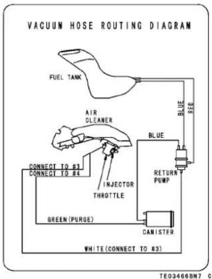
Valve Clearance
Valve and valve seat wear decreases valve clearance, upsetting valve timing.
NOTICE
If valve clearance is left unadjusted, wear will eventually cause the valves to remain partly open; which lowers performance, burns the valves and valve seats, and may cause serious engine damage.
Valve clearance for each valve should be checked and adjusted in accordance with the Periodic Maintenance Chart.
Inspection and adjustment should be carried out only by a competent mechanic following the instructions in the Service Manual.
MAINTENANCE AND ADJUSTMENT 203
Kawasaki Clean Air System
The Kawasaki Clean Air System (KCA) is a secondary air suction system that helps the exhaust gases to burn more completely. When the spent fuel charge is released into the exhaust system, it is still hot enough to burn. The KCA System allows extra air into the exhaust system so that the spent fuel charge can continue to burn. This continued burning action tends to burn up a great deal of the normally unburned gases, as well as changing a significant portion of the carbon monoxide into carbon dioxide.
Air Suction Valves -
The air suction valve is essentially a check valve which allows fresh air to flow only from the air cleaner into the exhaust port. Any air that has passed
the air suction valve is prevented from returning. Inspect the air suction valves in accordance with the Periodic Maintenance Chart. Also, inspect the air suction valves whenever stable idling cannot be obtained, engine power is greatly reduced, or there are abnormal engine noises.
Air suction valve removal and inspection should be carried out only by a competent mechanic following the instructions in the Service Manual.
204 MAINTENANCE AND ADJUSTMENT
Air Cleaner
A clogged air cleaner restricts the engine's air intake, increasing fuel consumption, reducing engine power, and causing spark plug fouling.
This motorcycle's air cleaner element consists of a wet paper filter, which cannot be cleaned.
The air cleaner element must be replaced in accordance with the Periodic Maintenance Chart. In dusty, rainy, or muddy conditions, the air cleaner element should be serviced more frequently than the recommended interval.
NOTICE
Use only the recommended air cleaner element (Kawasaki part number 11013-0014 or equivalent type). Using the any other air cleaner element will wear the engine prematurely or lower the engine performance.
Air Cleaner Element Removal
- Remove the fuel tank front cover by removing the bolts.

A. Bolts
B. Fuel Tank Front Cover
MAINTENANCE AND ADJUSTMENT 205
- Open the storage case lid.
- Remove the inner cover by removing the bolts and quick rivet.

A. Bolts
B. Quick Rivet
C. Inner Cover
206 MAINTENANCE AND ADJUSTMENT
- Remove the bolts and quick rivets.
- Pull the rear part of the rear middle fairing slowly to detach the projection, and then pull the rear middle fairing backward to detach the tabs.
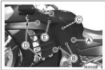
A. Bolts
B. Quick Rivets
C. Projection
D. Tabs
E. Rear Middle Fairing
- Remove the bracket by removing the bolts.
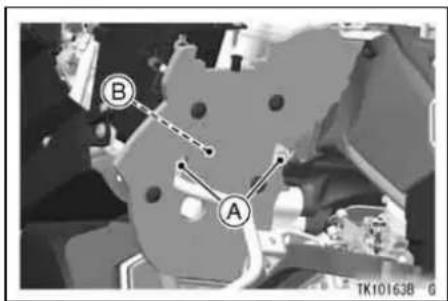
A. Bolts
B. Bracket
- Remove the air cleaner element cover by removing the bolts.
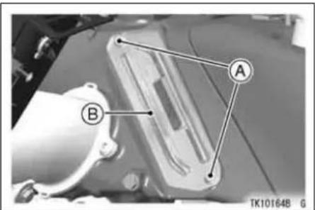
A. Bolts
B. Air Cleaner Element Cover
MAINTENANCE AND ADJUSTMENT
- Pull out the air cleaner element.

natural_image
Close-up of a mechanical component with a labeled section marked 'A' and no visible text or symbols beyond the label.A. Air Cleaner Element
WARNING
If dirt or dust is allowed to pass through into the throttle body assy, the throttle may stick or become inoperable resulting in a hazardous operating condition.
208 MAINTENANCE AND ADJUSTMENT
NOTICE
If dirt gets through into the engine, excessive engine wear and possibly engine damage will occur.
Air Cleaner Element Installation
Element and the removed parts installation is performed in the reverse order of removal, and make sure that the lead does not pinch with any parts.
- Install the air cleaner element cover so that arrow mark faces forward.

A. Air Cleaner Element Cover
B. Arrow Mark
- Insert the tabs on the lower part of the rear middle fairing, and then insert the tab on the upper part of the rear middle fairing, and attach the projection. Make sure the front end of the rear middle fairing is inserted into the hook of the front middle fairing.

A. Tabs (Lower Part)
B. Tab (Upper Part)
C. Projection
D. Hook
E. Rear Middle Fairing
F. Front Middle Fairing
- Be sure the storage case lid lock is locked correctly after installing the inner cover.
NOTE
○ The inner cover and the rear middle fairing use the quick rivets. The quick
MAINTENANCE AND ADJUSTMENT 209
rivets can be removed by pushing the central pin into the quick rivets, and when installing them, pull the central pin fully up first, and then push into the central pin after inserting them.
Quick Rivet Removal

A. Quick Rivet
B. Central Pin
C. Push in.
210 MAINTENANCE AND ADJUSTMENT
Quick Rivet Installation

A. Quick Rivet
B. Central Pin
C. Pull up fully.
D. Push in.
Oil Draining
- Inspect the transparent reservoir located under the left side of the engine to see if any oil has run down by removing the rear middle firing (see Air Cleaner Element Removal).

natural_image
Close-up of a motorcycle interior with a close-up view showing the wheel and side gear (no text or symbols visible)A. Reservoir
- If there is any oil in the reservoir, remove the reservoir and drain the oil.
WARNING
Oil on tires will make them slippery and can cause an accident and injury. Be sure to install the reservoir in the drain hose after draining.
Throttle Control System
Check the throttle grip play each day before riding the motorcycle, and in accordance with the Periodic Maintenance Chart. Adjust it if necessary.
Throttle Grip -
The throttle grip controls the butterfly valves in the throttle body. If the throttle grip has excessive play due to either cable stretch or maladjustment, it will cause a delay in throttle response, especially at low engine speed. Also, the throttle valve may not open fully at full throttle. On the other hand, if the throttle grip has not play, the throttle will be hard to control, and the idle speed will be erratic.
Inspection
- Check that the throttle grip play is correct by lightly turning the throttle grip back and forth.

A. Throttle Grip
B. Throttle Grip Play
Throttle Grip Play
2\~3 mm (0.08\~0.12 in.)
- If there is improper play, adjust it.
Adjustment
- Loosen the locknuts at the lower ends of the throttle cables, and screw
212 MAINTENANCE AND ADJUSTMENT
both throttle cable adjusters in completely so as to give the throttle grip plenty of play.
- Turn out the decelerator cable adjuster until there is no play when the throttle grip is completely closed. Tighten the locknut against the adjuster.
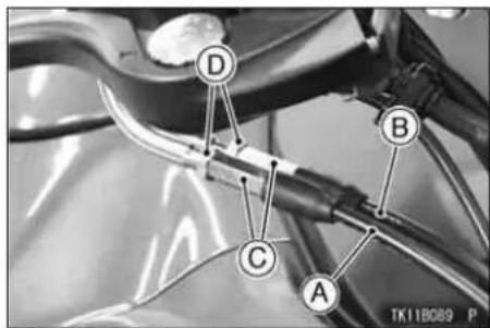
A. Decelerator Cable
B. Accelerator Cable
C. Adjusters
D. Locknuts
- Turn out the accelerator cable adjuster until 2 \~ 3 mm (0.08 \~ 0.12 in.) of throttle grip play is obtained. Tighten the locknut against the adjuster.
- If the throttle cables cannot be adjusted with the adjuster at the upper of the throttle cable, further adjustment of the throttle cables should be done by a competent mechanic following the instructions in the Service Manual.
- With the engine idling, turn the handlebar to each side. If handlebar movement changes the idle speed, the throttle cables may be improperly adjusted or in correctly routed, or they may be damaged. Be sure to correct any of these conditions before idling.
WARNING
Operation with improperly adjusted, incorrectly routed or damaged cables could result in an unsafe riding condition. Follow the service manual to be make sure to correct any of these conditions.
MAINTENANCE AND ADJUSTMENT 213
Engine Vacuum Synchronization
Engine vacuum synchronization must be checked and adjusted periodically in accordance with the Periodic Maintenance Chart by a competent mechanic following the instructions in the Service Manual.
NOTE
○ Poor engine vacuum synchronization will cause unstable idling, sluggish throttle response, and reduce engine power and performance.
214 MAINTENANCE AND ADJUSTMENT
Idle Speed
The idle speed adjustment should be performed in accordance with the Periodic Maintenance Chart or whenever the idle speed is disturbed.
Adjustment
- Start the engine, and warm it up thoroughly.
- Adjust the idle speed by turning the idle adjusting screw.
Idle Speed
1 050 \~ 1 150 r/min (rpm)

natural_image
Close-up of a motorcycle engine component with a magnified inset showing a section labeled 'A' (no text or symbols on the main subject)A. Idle Adjusting Screw
- Open and close the throttle a few times to make sure that the idle speed does not change. Readjust if necessary.
- With the engine idling, turn the handlebar to each side. If handlebar movement changes the idle speed, the throttle cables may be improperly adjusted or incorrectly routed, or they may be damaged. Be sure to correct any of these conditions before riding.
WARNING
Operation with damaged cables could result in an unsafe riding condition. Replace damaged control cables before operation.
MAINTENANCE AND ADJUSTMENT 215
Clutch
The motorcycle is equipped with a hydraulically operated clutch that requires no adjustment except fluid level and clutch operation inspection each day before riding the motorcycle in accordance with the Periodic Maintenance Chart.
Clutch Operation Inspect
- If the clutch lever play becomes excessive and the motorcycle creeps or stalls when shifted into gear, there is probably air in the clutch system and it must be bled out by an authorized Kawasaki dealer.
216 MAINTENANCE AND ADJUSTMENT
Fluid Level Inspection
- With the clutch fluid reservoir held horizontal, the clutch fluid level must be kept between the upper and lower level lines.
- If the fluid level is lower than the lower level line, check for fluid leaks in the clutch line, and fill the clutch fluid reservoir to the upper level line.

A. Upper Level Line
B. Lower Level Line
C. Clutch Fluid Reservoir
NOTE
○Use the same fluid as is used in the brakes and keep the same requirements mentioned in the Brakes section.
Brakes
Brake Wear Inspection
Inspect the brakes for wear. For each front and rear disc brake caliper, if the thickness of either pad linning is less than 1 mm (0.04 in.), replace both pads in the caliper as a set. Pad replacement should be done by an authorized Kawasaki dealer.

A. Lining Thickness
B. 1 mm (0.04 in.)
MAINTENANCE AND ADJUSTMENT
Disc Brake Fluid -
In accordance with the Periodic Maintenance Chart, inspect the brake fluid level in both the front and rear brake fluid reservoirs and change the brake fluid. The brake fluid should also be changed if it becomes contaminated with dirt or water.
Fluid Requirement
Use DOT4 rated heavy-duty brake fluid only.
NOTICE
Do not spill brake fluid onto any painted surface.
Do not use fluid from a container that has been left open or that has been unsealed for a long time.
Check for fluid leakage around the fittings.
Check brake hose for damage.
218 MAINTENANCE AND ADJUSTMENT
Fluid Level Inspection
- With the brake fluid reservoirs held horizontal, the brake fluid level must be kept between the upper and lower level lines.

A. Front Brake Fluid Reservoir
B. Upper Level Line
C. Lower Level Line
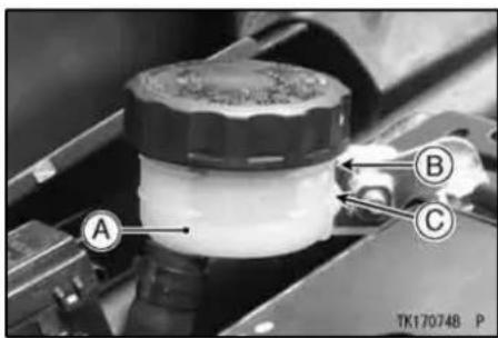
A. Rear Brake Fluid Reservoir
B. Upper Level Line
C. Lower Level Line
- If the fluid level in either reservoir is lower than the lower level line, check for fluid leaks in the brake lines, and fill the reservoir to the upper level line.
WARNING
Mixing brands and types of brake fluid can reduce the brake system's effectiveness and cause an accident resulting in injury or death. Do not mix two brands of brake fluid. Change the brake fluid in the brake line completely if the brake fluid must be refilled but the type and brand of the brake fluid that is already in the reservoir are unidentified.
NOTE
○ First, tighten until slight resistance is felt indicating that the cap is seated on the reservoir body; tighten the cap an additional 1/6 turn while holding the brake fluid reservoir body.
MAINTENANCE AND ADJUSTMENT 219

A. Reservoir
B. Cap
C. Clockwise
D. 1/6 turn
Fluid Change
Have the brake fluid changed by an authorized Kawasaki dealer.
Front and Rear Brakes -
Disc and disc pad wear is automatically compensated for and has no effect on the brake lever or pedal action.
220 MAINTENANCE AND ADJUSTMENT
So there are no parts that require adjustment on the front or rear brakes.
WARNING
Air in the brake lines diminish braking performance and can cause an accident resulting in injury or death. If the brake lever or pedal feels mushy when it is applied, there might be air in the brake lines or the brake may be defective. Have the brake checked immediately by an authorized Kawasaki dealer.
Brake Light Switches
When either the front or rear brake is applied, the brake light goes on. The front brake light switch requires no adjustment, but the rear brake light switch should be adjusted in accordance with the Periodic Maintenance Chart.
Inspection
- Turn the ignition key to ON.
- The brake light should go on when the front brake is applied.
- If it does not, ask your authorized Kawasaki dealer to inspect the front brake light switch.
- Check the operation of the rear brake light switch by depressing the brake pedal. The brake light should go on after the proper pedal travel.

A. Brake Pedal
B. 10 mm (0.39 in.)
- If the light does not go on, adjust the rear brake light switch.
Brake Pedal Travel
10 mm (0.39 in.)
MAINTENANCE AND ADJUSTMENT
Adjustment
- To adjust the rear brake light switch, move the switch up or down by turning the adjusting nut.
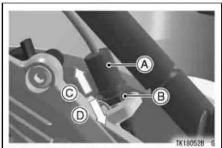
A. Rear Brake Light Switch
B. Adjusting Nut
C. Lights sooner
D. Lights later
222 MAINTENANCE AND ADJUSTMENT
NOTICE
To avoid damaging the electrical connections inside the switch, be sure that the switch body does not turn during adjustment.
Front Fork
The front fork operation and oil leakage should be checked in accordance with the Periodic Maintenance Chart.
Front Fork Inspection
- Holding the brake lever, pump the front fork up and down several times to inspect smooth stroke.
- Visually inspect the front fork for oil leakage, scoring or scratches on the outer surface of the inner tube.
- If any doubt about the front fork, it should be done by an authorized Kawasaki dealer.

natural_image
Close-up of a mechanical component with labeled point A, no readable text or symbols presentA. Inner Tube
On top of each front fork leg are a spring preload adjuster and a rebound damping force adjuster, so that the spring force and damping force can be
MAINTENANCE AND ADJUSTMENT
adjusted for different riding and loading conditions. Weaker spring force and damping force are for comfortable riding, but they should be increased for high speed riding or riding on rough roads.
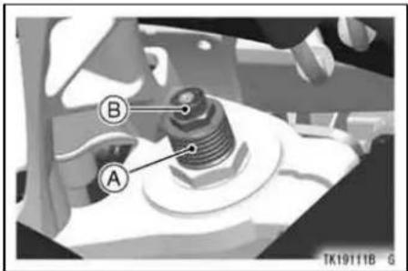
A. Spring Preload Adjuster
B. Rebound Damping Force Adjuster
224 MAINTENANCE AND ADJUSTMENT
NOTICE
Do not force to turn the rebound damping force adjuster from the fully seated position, at the adjusting mechanism may be damaged.
Spring Preload Adjustment
- Turn the spring preload adjusters into the nut to increase spring force and out to decrease spring force using the wrench. The adjusting range is measured from the top of each adjuster. Be sure to turn both adjusters to the same position.

A. Spring Preload Adjuster
B. Wrench
C. Adjustable Range
Adjusting Range
$$ 4 \sim 1 9 \mathrm{mm} (0. 1 6 \sim 0. 7 5 \text { in . }) $$
Rebound Damping Force Adjustment
- Turn the rebound damping force adjuster clockwise. This makes the damping force greatest.
- Turn the adjuster counterclockwise to decrease damping force. Be sure to turn both adjusters by the same number of turns.
WARNING
If both spring preload adjusters and both rebound damping force adjusters are not adjusted equally, handling may be impaired and hazardous condition may result. Always adjust the suspension components equally.
The standard setting positions of the spring preload adjuster, and rebound damping force adjuster for an average -build rider of 68 kg (150 lb) with no
MAINTENANCE AND ADJUSTMENT 225
passenger and no accessories are as follows:
| Spring Preload Adjuster | 14 mm (0.55 in.) from top of adjuster |
| Rebound Damping Force Adjuster | 5 clicks* |
*: counterclockwise from the fully seated position (strongest position)
226 MAINTENANCE AND ADJUSTMENT
Rear Shock Absorber
The rear shock absorber operation and oil leakage should be checked in accordance with the Periodic Maintenance Chart.
Rear Shock Absorber Inspection
- Press down on the seat several times to inspect the stroke.
- Visually inspect the rear shock absorber for oil leakage.
- If any doubt about the rear shock absorber, it should be done by an authorized Kawasaki dealer.

natural_image
Medical illustration showing a surgical procedure with labeled point A (no text or symbols beyond label)A. Rear Shock Absorber
The rear shock absorber can be adjusted by changing the spring preload and rebound damping force for various riding and loading conditions.
Before making any adjustments, however, read the following procedures:
NOTICE
Do not force to turn the rebound damping force adjuster from the fully seated position or the adjusting mechanism may be damaged.
MAINTENANCE AND ADJUSTMENT
Spring Preload Adjustment
- Turn the adjuster in or out to the desired position.
- Turning the adjuster clockwise increases the spring preload, and turning it counterclockwise decreases the spring preload.

natural_image
Mechanical assembly diagram showing a valve with labeled component A, no readable text or symbols presentA. Adjuster
228 MAINTENANCE AND ADJUSTMENT
Rebound Damping Force Adjustment
The rebound damping force adjuster is located at the lower end of the rear shock absorber.

natural_image
Mechanical assembly diagram showing a lever and shaft assembly with labeled component A (no readable text or symbols beyond label)A. Rebound Damping Force Adjuster
- Turn the rebound damping force adjuster all the way clockwise with a screwdriver to make the damping force greatest.
- Turn the adjuster counterclockwise to decrease damping force.
The standard setting position of the spring preload adjuster and rebound damping force adjuster for an average -build rider of 68 kg (150 lb) with no passenger and no accessories is as follows:
| Spring Preload Adjuster | 12 clicks* |
| Rebound Damping Force Adjuster | 1 1/4 turns out** |
*: clockwise from the fully seated position (weakest position)
**: counterclockwise from the fully seated position (strongest position)
Wheels
Tubeless tires are installed on the wheels of this motorcycle. The indications of TUBELESS on the tire side wall and the rim show that the tire and rim are specially designed for tubeless use.
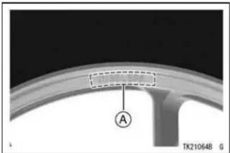
A. TUBELESS Mark
MAINTENANCE AND ADJUSTMENT 229

natural_image
Mechanical gear assembly with labeled component A (no readable text or symbols beyond label)A. TUBELESS Mark
The tire and rim form a leakproof unit by making airtight contacts at the tire chamfers and the rim flanges instead of using an inner tube.
230 MAINTENANCE AND ADJUSTMENT
WARNING
Installing a tube inside a tubeless-type tire can create excessive heat build up that can damage the tube and cause rapid deflation. The tires, rims, and air valves on this motorcycle are designed only for tubeless type wheels. The recommended standard tires, rims, and air valves must be used for replacement. Do not install tube-type tires on tubeless rims. The beads may not seat properly on the rim causing tire deflation. Do not install a tube inside a tubeless tire. Excessive heat build-up may damage the tube causing tire deflation.
Tire Sealants
Internal tire sealants or repair products can cause damage to the tire pressure sensor(s) and should not be used.
Tires -
Payload and Tire Pressure
Failure to maintain proper inflation pressures or observe payload limits for your tires may adversely affect handling and performance of your motorcycle and can result in loss of control. The maximum recommended load in addition to vehicle weight is 228 kg (503 lb), including rider, passenger, baggage, and accessories.
- Remove the air valve cap.
- Check the tire pressure often, using an accurate gauge.
● Make sure to install the air valve cap securely.
MAINTENANCE AND ADJUSTMENT
NOTE
○Measure the tire pressure when the tires are cold (that is, when the motorcycle has not been ridden more than a mile during the past 3 hours).
○ Tire pressure is affected by changes in ambient temperature and altitude, and so the tire pressure should be checked and adjusted when your riding involves wide variations in temperature or altitude.
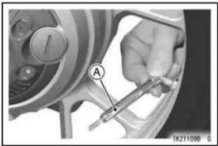
A. Tire Pressure Gauge
Tire Air Pressure (when cold)
| Front | 290 kPa (2.90 kgf/cm2, 42 psi) |
| Rear | 290 kPa (2.90 kgf/cm2, 42 psi) |
Tire Wear, Damage
As the tire tread wears down, the tire becomes more susceptible to puncture and failure. An accepted estimate is that 90% of all tire failures occur during the last 10% of tread life (90% worn).
232 MAINTENANCE AND ADJUSTMENT
So it is false economy and unsafe to use the tires until they are bald.
- In accordance with the Periodic Maintenance Chart, measure the depth of the tread with a depth gauge, and replace any tire that has worn down to the minimum allowable tread depth.

A. Tire Depth Gauge
Minimum Tread Depth
| Front | - | 1 mm (0.04 in.) |
| Rear | Under 130 km/h (80 mph) | 2 mm (0.08 in.) |
| Over 130 km/h (80 mph) | 3 mm (0.12 in.) |
- Visually inspect the tire for cracks and cuts, replacing the tire in case of bad damage. Swelling or high spots indicate internal damage, requiring tire replacement.
- Remove any imbedded stones or other foreign particles from the tread.
NOTE
○Have the wheel balance inspected whenever a new tire is installed.
| WARNING |
| Tires that have been punctured and repaired do not have the same capabilities as undamaged tires and can suddenly fail, causing an accident resulting in serious injury or death. Replace damaged tires as soon as possible. To ensure safe handling and stability, use only the recommended standard tires for replacement, inflated to the standard pressure. If it is necessary to ride on a repaired tire, do not exceed 100 km/h (60 mph) until the tire is replaced. |
NOTE
○ When operating on public roadways, keep maximum speed under traffic law limits.
MAINTENANCE AND ADJUSTMENT 233
Standard Tire (Tubeless)
| Front | Make, Type:BRIDGESTONE,BATTLAX BT021F USize:120/70 ZR17 M/C (58W) |
| Make, Type:BRIDGESTONE,BATTLAX BT021F MSize:120/70 ZR17 M/C (58W) | |
| Rear | Make, Type:BRIDGESTONE,BATTLAX BT021R USize:190/50 ZR17 M/C (73W) |
234 MAINTENANCE AND ADJUSTMENT
WARNING
Mixing tire brands and types can adversely affect handling and cause an accident resulting in injury or death. Always use the same manufacturer's tires on both front and rear wheels.
WARNING
New tires are slippery and may cause loss of control and injury. A break-in period of 160 km (100 miles) is necessary to establish normal tire traction. During break-in, avoid sudden and maximum braking and acceleration, and hard cornering.
Battery
The battery installed in this motorcycle is a sealed type, so it is not necessary to check the battery electrolyte level or add distilled water.
The sealing strip should not be pulled off once the specified electrolyte has been installed in the battery for initial service.
However, in order to maximize battery life and ensure that it will provide the power needed to start the motorcycle you must properly maintain the battery's charge. When used regularly, the charging system in the motorcycle helps keep the battery fully charged. If your motorcycle is only used occasionally or for short periods of time, the battery is more likely to discharge.
Due to their internal composition, batteries continually self discharge. The discharge rate depends on the
MAINTENANCE AND ADJUSTMENT 235
type of battery and ambient temperature. As temperatures rise, so does the discharge rate. Every 15°C (27°F) doubles the rate.
Electrical accessories, such as digital clocks and computer memory, also draw current from the battery even when the key is switched off. Combine such "key-off" draws with hot temperature, and a battery can go from fully charged to completely discharged in a matter of days.
| Self-discharge | ||
| Temperature | Approx. number of days from 100% charged to 100% discharged | |
| Lead-Antimony | Lead-Calcium | |
| Battery | Battery | |
| 40°C (104°F) | 100 Days | 300 Days |
| 25°C (77°F) | 200 Days | 600 Days |
| 0°C (32°F) | 550 Days | 950 Days |
236 MAINTENANCE AND ADJUSTMENT
| Current Drain | ||
| Discharging Ampere | Days from 100% charged to 50% discharged | Days from 100% charged to 100% discharged |
| 7 mA | 60 Days | 119 Days |
| 10 mA | 42 Days | 83 Days |
| 15 mA | 28 Days | 56 Days |
| 20 mA | 21 Days | 42 Days |
| 30 mA | 14 Days | 28 Days |
In extremely cold weather the fluid in an inadequately charged battery can easily freeze, which can crack the case and buckle the plates. A fully charged battery can withstand sub-freezing temperatures with no damage.
Battery Sulfation -
A common cause of battery failure is sulfation.
Sulfation occurs when the battery is left in a discharged condition for an extended time. Sulfate is a normal by product of the chemical reactions within a battery. But when continuous discharge allows the sulfate to crystallize in the cells, the battery plates become permanently damaged and will not hold a charge. Battery failure due to sulfation is not warrantable.
Battery Maintenance -
It is the owner's responsibility to keep the battery fully charged. Failure to do so can lead to battery failure and leave you stranded.
If you are riding your vehicle infrequently, inspect the battery voltage weekly using a voltmeter. If it drops below 12.6 volts, the battery should be charged using an appropriate charger (check with your Kawasaki dealer).
If you will not be using the motorcycle for longer than two weeks, the battery should be charged using an appropriate charger. Do not use an automotive-type quick charger that may overcharge the battery and damage it.
Kawasaki-recommended chargers are:
OptiMate III
Yuasa 1.5 Amp Automatic charger Battery Mate 150-9
If the above chargers are not available, use equivalent one.
For more details, ask your Kawasaki dealer.
Battery Charging -
- Remove the battery from the motorcycle (see Battery Removal).
- Attach the leads from the charger and charge the battery at a rate that is 1/10th of the battery capacity. For
MAINTENANCE AND ADJUSTMENT
example, the charging rate for a 10 Ah battery would be 1.0 ampere.
● The charger will keep the battery fully charged until you are ready to reinstall the battery in the motorcycle (see Battery Installation).
NOTICE
Never remove the sealing strip, or the battery can be damaged. Do not install a conventional battery in this motorcycle, or the electrical system cannot work properly.
NOTE
○If you charge the sealed battery, never fail to observe the instructions shown in the label on the battery.
238 MAINTENANCE AND ADJUSTMENT
WARNING
Lead is a toxic substance. Battery posts, terminals and related accessories contain lead and lead compounds. Wash hands after handling.
Battery Removal
- Remove the bolt.
- Remove the sub side cover by pulling out it to detach the projection.
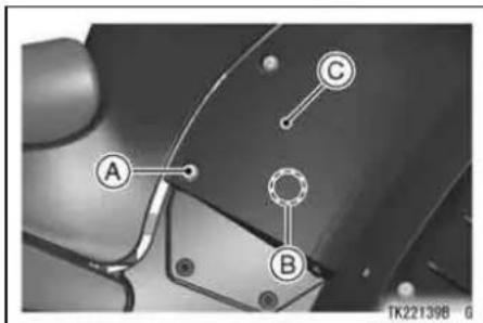
A. Bolt
B. Projection
C. Sub Side Cover
- Remove the battery cover by removing the bolts.

A. Bolts
B. Battery Cover
MAINTENANCE AND ADJUSTMENT 239
- Remove the battery (−) cable and frame ground cable by removing the bolt.
- Pull the battery holder a little, and remove the battery (+) cable from the battery.
- Pull out the battery holder.
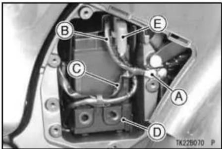
A. Bolt
B. Battery (−) Cable
C. Frame Ground Cable
D. Battery Holder
E. Battery (+) Cable
240 MAINTENANCE AND ADJUSTMENT
NOTICE
Be careful not to drop the battery from the motorcycle when pulling out it.
Do not give the battery tray a strong pull, or the cables may be damaged.
- Detach the hook, and separate the cover and holder.
- Remove the battery (−) cable from the battery.

A. Cover
B. Hook
C. Battery Holder
D. Battery (−) Cable
- Clean the battery using a solution of baking soda and water. Be sure that the wire connections are clean.
Battery Installation
Battery and the removed parts installation is performed in the reverse order of removal, and make sure that the lead or cable does not pinch with any parts.
- Insert the projections on the battery holder into the holes of the battery holder compartment.

A. Battery Holder
B. Projections
C. Holes
MAINTENANCE AND ADJUSTMENT 241
- First, install the battery (+) cable from the battery, and then install the battery (−) cable from the frame.

A. Battery (+) Cable
B. Battery (−) Cable
242 MAINTENANCE AND ADJUSTMENT
NOTICE
Installing the (-) cable to the (+) terminal of the battery or the (+) cable to the (-) terminal of the battery can cause seriously damage to the electrical system.
- Insert the projections on the battery cover into the holes of the battery holder.

A. Battery Cover
B. Projections
C. Battery Holder
D. Holes
- Insert the tabs on the sub side cover into the under of the rear middle fairing, and insert the projection on the sub side cover into the hole on the battery cover.

A. Tabs
B. Projections
C. Sub Side Cover
MAINTENANCE AND ADJUSTMENT 243
Headlight Beam
Horizontal Adjustment
The headlight beam is adjustable horizontally. If not properly adjusted horizontally, the beam will point to one side rather than straight ahead.
● Turn the horizontal adjuster in or out until the beam points straight ahead.
Vertical Adjustment
The headlight beam is adjustable vertically. If adjusted too low, neither low nor high beam will illuminate the road far enough ahead. If adjusted too high, the high beam will fail to illuminate the road close ahead, and the low beam will blind oncoming drivers.

A. 50 mm (2.0 in.)
B. Center of Brightest Spot
C. 7.6 m (25 ft)
D. Height of Headlight Center
MAINTENANCE AND ADJUSTMENT
Fuses
Fuses are arranged in the fuse boxes located under the seat. The main fuse is located at the battery compartment. If a fuse fails during operation, inspect the electrical system to determine the cause, and then replace it with a new fuse of proper amperage.

A. Fuse Boxes
246 MAINTENANCE AND ADJUSTMENT

natural_image
Close-up of a mechanical component with labeled parts (A and P), no readable text or symbols beyond labelsA. Main Fuse
WARNING
Substituting fuses can cause wiring to overheat, catch fire and/or fail. Do not use any substitute for the standard fuse. Replace the blown fuse with a new one of the correct capacity, as specified on the fuse boxes and main fuse.

natural_image
Two technical diagrams labeled A and B showing internal components with curved lines, no text or symbols present.A. Normal
B. Failed
MAINTENANCE AND ADJUSTMENT 247
General Lubrication
Lubricate the points shown below, with either motor oil or regular grease, in accordance with the Periodic Maintenance Chart or whenever the vehicle has been operated under wet or rainy conditions.
Before lubricating each part, clean off any rusty spots with rust remover and wipe off any grease, oil, dirt, or grime.
NOTE
○A few drops of oil are effective to keep bolts and nuts from rusting and sticking. This makes removal easier. Badly rusted nuts, bolts, etc., should be replaced with new ones.
Apply motor oil to the following pivots -
○Side Stand
○Center Stand
○Clutch Lever
○Front Brake Lever
○Rear Brake Pedal
Lubricate the following cables with a pressure cable lubber -
○(K) Throttle Inner Cables

natural_image
Line drawing of two hands holding a syringe and a bulb, no text or symbols present248 MAINTENANCE AND ADJUSTMENT
Apply grease to the following points -
○(K) Throttle Inner Cable Upper Ends
(K): Should be serviced by an authorized Kawasaki dealer.
NOTE
○After connecting the cables, adjust them.
Cleaning Your Motorcycle
General Precautions
Frequent and proper care of your Kawasaki motorcycle will enhance its appearance, optimize overall performance, and extend its useful life. Covering your motorcycle with a high quality, breathable motorcycle cover will help protect its finish from harmful UV rays, pollutants, and reduce the amount of dust reaching its surfaces.
- Be sure the engine and exhaust are cool before washing.
- Avoid applying degreaser to seals, brake pads, and tires.
- Avoid all harsh chemicals, solvents, detergents, and household cleaning products such as ammonia-based window cleaners.
● Gasoline, brake fluid, clutch fluid, and coolant will damage the finish of
painted and plastic surfaces: wash them off immediately.
- Avoid wire brushes, steel wool, and all other abrasive pads or brushes.
- Use care when washing the windshield, headlight cover, and other plastic parts as they can easily be scratched.
- Avoid using pressure washers; water can penetrate seals and electrical components and damage your motorcycle.
- Avoid spraying water in delicate areas such as in air intakes, fuel system, brake components, electrical components, electrical socket, muffler outlets, and fuel tank openings.
MAINTENANCE AND ADJUSTMENT 249
- After cleaning your motorcycle, check the rubber boot covering the shift pedal ball joint for correct installation. Be sure the sealing lip of the rubber boot fits into the groove of the ball joint.

natural_image
Mechanical assembly diagram showing a vehicle chassis with labeled components (no readable text or symbols)A. Rubber Boot
250 MAINTENANCE AND ADJUSTMENT
- If the boot is damaged, replace it with a new one. If the boot is not positioned in the groove correctly, replace it in the correct position.

natural_image
Two identical black plastic pipe fittings labeled A and B, shown side by side (no text or symbols on the parts themselves)A. Not Position
B. Correct Position
Washing Your Motorcycle
- Rinse your bike with cold water from a garden hose to remove any loose dirt.
- Mix a mild neutral detergent (designed for motorcycles or automobiles) and water in a bucket. Use a soft cloth or sponge to wash your motorcycle. If needed, use a mild degreaser to remove any oil or grease build up.
- After washing, rinse your motorcycle thoroughly with clean water to remove any residue (residue from the detergent can damage parts of your motorcycle).
- Use a soft cloth to dry your motorcycle. As you dry, inspect your motorcycle for chips and scratches. Do not let the water air dry as this can damage the painted surfaces.
- Start the engine and let it idle for several minutes. The heat from the engine will help dry moist areas.
- Carefully ride your motorcycle at a slow speed and apply the brakes several times. This helps dry the
brakes and restores them to normal operating performance.
NOTE
○ After riding in an area where the roads are salted or near the ocean, immediately wash your motorcycle with cold water. Do not use warm water as it accelerates the chemical reaction of the salt. After drying, apply a corrosion protection spray on all metal and chrome surfaces to prevent corrosion.
○ Condensation may form on the inside of the headlight lens after riding in the
MAINTENANCE AND ADJUSTMENT 251
rain, washing the motorcycle or humid weather. To remove the moisture, start the engine and turn on the headlight. Gradually the condensation on the inside of the lens will clear off.
Windshield and Other Plastic Parts
After washing use a soft cloth to gently dry plastic parts. When dry, treat the windshield, headlight lens, and other nonpainted plastic parts with an approved plastic cleaner/polisher product.
252 MAINTENANCE AND ADJUSTMENT
NOTICE
Plastic parts may deteriorate and break if they come in contact with chemical substances or household cleaning products such as gasoline, brake fluid, window cleaners, thread-locking agents, or other harsh chemicals. If a plastic part comes in contact with any harsh chemical substance, wash it off immediately with water and a mild neutral detergent, and then inspect for damage. Avoid using abrasive pads or brushes to clean plastic parts, as they will damage the part's finish.
Chrome and Aluminum
Chrome and uncoated aluminum parts can be treated with a chrome/aluminum polish. Coated aluminum should be washed with a mild neutral detergent and finished with a spray polish. Aluminum wheels, both painted and unpainted can be cleaned with special non-acid based wheel spray cleaners.
Leather, Vinyl, and Rubber
If your motorcycle has leather accessories, special care must be taken. Use a leather cleaner/treatment to clean and care for leather accessories. Washing leather parts with detergent and water will damage them, shortening their life.
Vinyl parts should be washed with the rest of the motorcycle, then treated with a vinyl treatment.
The sidewalls of tires and other rubber components should be treated with a rubber protectant to help prolong their useful life.
WARNING
Rubber protectants can be slippery and, if used on the tread area, cause loss of traction resulting in accident causing injury or death. Do not apply rubber protectant to any tread area.
254 MAINTENANCE AND ADJUSTMENT
Bolt and Nut Tightening
In accordance with the Periodic Maintenance Chart, it is very important to check the tightness of the bolts and nuts listed here. Also, check to see that each cotter pin is in place and in good condition. Please ask your authorized Kawasaki dealer for torque values.
- Clutch Lever Holder Bolts
- Steering Stem Head Bolt
- Handlebar Mounting Bolts
- Front Fork Clamp Bolts
- Brake Lever Holder Clamp Bolts

- Front Fender Mounting Bolts
- Engine Mounting Bolts and Nuts
- Rear Frame Mounting Bolts
- Brake Disc Mounting Bolts
- Front Axle Clamp Bolts
- Front Axle
- Caliper Mounting Bolts
- Side Stand Bolt
- Swingarm Pivot Shaft Nut
- Uni-trak Lever Rod Nuts
- Footpeg Mounting Bolts
- Rear Shock Absorber Mounting Nuts
- Front Gear Case Mounting Bolts
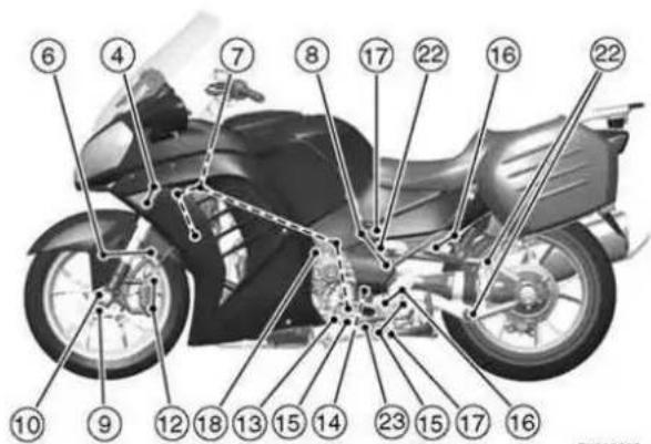
TK28099B G
256 MAINTENANCE AND ADJUSTMENT
- Silencer Mounting Bolts
- Brake Pedal Bolt
- Rear Axle Nut
- Tetra Lever Bolts
- Center Stand Bolts and Nuts

TK281008 G
STORAGE
Preparation for Storage
- Clean the entire vehicle thoroughly.
- Run the engine for about five minutes to warm the oil, shut it off, and drain the engine oil.
WARNING
Motorcycle oil is a toxic substance. Dispose of used oil properly. Contact your local authorities for approved disposal methods or possible recycling.
- Put in fresh engine oil.
● Empty the fuel from the fuel tank by the pump or siphon.
258 STORAGE
WARNING
Gasoline is extremely flammable and can be explosive under certain conditions. Turn the ignition switch to "OFF". Do not smoke. Make sure the area is well-ventilated and free from any source of flame or sparks; this includes any appliance with a pilot light. Gasoline is a toxic substance. Dispose of gasoline properly. Contact your local authorities for approved disposal methods.
- Empty the fuel system by running the engine at idle speed until the engine stalls (If left in for a long time, the fuel will break down and could clog the fuel system.).
- Reduce tire pressure by about 20%.
- Set the motorcycle on a box or stand so that both wheels are raised off the ground (If this cannot be done, put boards under the front and rear wheels to keep dampness away from the tire rubber.).
- Spray oil on all unpainted metal surfaces to prevent rusting. Avoid getting oil on rubber parts or in the brakes.
- Remove the battery, and store it where it will not be exposed to direct sunlight, moisture, or freezing temperatures. During storage it should be given a slow charge (one ampere or less) about once a month. Keep the battery well charged especially during cold weather.
- Tie a plastic bag over the muffler to prevent moisture from entering.
- Put a cover over the motorcycle to keep dust and dirt from collecting on it.
STORAGE 259
Preparation after Storage
- Remove the plastic bag from the muffler.
● Install the battery in the motorcycle and charge the battery if necessary. - Fill the fuel tank with fuel.
- Check all the points listed in the Daily Safety Checks section.
● Lubricate the pivots, bolts, and nuts.

TROUBLESHOOTING GUIDE
Engine Does Not Start -
Starter Motor Won't Turn
● Engine stop switch off
● Transmission not in neutral
- Fuse blown
● Battery leads do not make good electrical contact with battery terminals
● Battery discharged
Engine Cranks, But Won't Start
- No fuel in tank
- Fuel line clogged
● Fuel broken down - Engine flooded
- Spark plugs not in good contact
- Spark plugs fouled or wet
- Incorrect spark plug gap
- Incorrect valve clearance
- Battery discharged
- No first turning the ignition key to "OFF" when the motorcycle falls down.
Engine Stalls -
Just When Shifting Into 1st Gear
- Side stand has been left down
- Clutch does not properly disengage
While Riding
- No fuel in tank
● Fuel tank air vent is obstructed
• Overheating - Battery discharged
OWNER SATISFACTION
(For Products Sold in the Continental United States of America Only)
Your satisfaction is important to your authorized Kawasaki dealer and to Kawasaki Motors Corp., U.S.A. If you have a problem concerning warranty or service, please take the following action:
Contact the owner and/or service manager of your authorized Kawasaki dealer. Fully explain your problem and ask for assistance in resolving the situation. The OWNER of the dealership is concerned with your satisfaction and your future business. For this reason the owner is in the best position to assist you. Also, all warranty and service matters are handled and resolved through the authorized Kawasaki dealer network.
If you are unsatisfied after working with your Kawasaki dealer and feel you still require further assistance, write to the address below. Please be certain to provide the model, product identification number, mileage or hours of use, accessories, dates that events occurred and what action has been taken by both you and your dealer. Include the name and address of the dealership. To assist us in resolving
262 OWNER SATISFACTION
your inquiry, please include copies of related receipts and any other pertinent information including the names of the dealership personnel with whom you have been working in the resolution of your problem.
Upon receipt of your correspondence we will contact the dealership and work with them in resolving your problem.
In order to provide a permanent record, all warranty and service resolutions take place only through written correspondence.
Please send your correspondence to:
CONSUMER RELATIONS
KAWASAKI MOTORS CORP., U.S.A.
P. O. Box 25252
SANTA ANA, CA. 92799-5252
(949) 460-5688
REPORTING SAFETY DEFECTS
(For Products Sold in the Continental United States of America Only)
If you believe that your vehicle has a defect which could cause a crash or could cause injury or death, you should immediately inform the National Highway Traffic Safety Administration (NHTSA) in addition to notifying Kawasaki Motors Corporation, U.S.A.
If NHTSA receives similar complaints, it may open an investigation, and if it finds that a safety defect exists in a group of vehicles, it may order a recall and remedy campaign. However, NHTSA cannot become involved in individual problems between you, your dealer, or Kawasaki Motors Corporation, U.S.A.
To contact NHTSA, you may either call the Auto Safety Hotline toll-free at 1-800-424-9393 (or 366-0123 in Washington, D.C. area) or write to: NHTSA, U.S. Department of Transportation, Washington, D.C. 20590. You can also obtain other information about motor vehicle safety from the Hotline.
264 ENVIRONMENTAL PROTECTION
ENVIRONMENTAL PROTECTION
To protect our environment, properly discard used batteries, tires, engine oil, or other vehicle components that you might dispose of in the future. Consult your authorized Kawasaki dealer or local environmental waste agency for their proper disposal procedures.
MAINTENANCE RECORD
Owner Name....
Address ....
Phone Number....
Engine Number....
Vehicle Number......
Selling Dealer Name ....
Phone Number......
Warranty Start Date ....
Note: Keep this information and a spare key in a secure location.
| Date | Odometer Reading | Maintenance Performed | Dealer Name | Dealer Address |
266 MAINTENANCE RECORD
| Date | Odometer Reading | Maintenance Performed | Dealer Name | Dealer Address |
268 MAINTENANCE RECORD
| Date | Odometer Reading | Maintenance Performed | Dealer Name | Dealer Address |
LOCATION OF LABELS
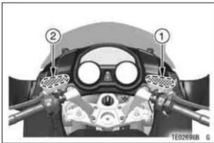
natural_image
Top-down view of a mechanical device with labeled components (no readable text or symbols)

- Brake Fluid (Front)
- Clutch Fluid
- Tire and Load Data
- Vehicle Emission Control Information
- Fuel Notice
- Fuel Level
*: only on California model
270 LOCATION OF LABELS

natural_image
Close-up of a mechanical component with labeled parts, no visible text or symbols

natural_image
Close-up mechanical assembly with numbered component (8) and no visible text or symbols-
Weight and Manufacture
-
Noise Emission Control Information
*9. Vacuum Hose Routing Diagram
-
Daily Safety Checks
-
Brake Fluid (Rear)
*: only on California model

natural_image
Close-up of a mechanical component with a numbered label (12) and alphanumeric identifier TE02340B, no readable text or symbols beyond the label.
natural_image
3D rendered mechanical component with numbered annotation (13), no readable text or symbols beyond the label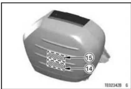
natural_image
3D model of a gray object with a grid pattern and numbered annotations (14, 15), no readable text or symbols beyond labels.- Saddlebag Notice
- Saddlebag Lock Notice
- Saddlebag Limit Notice (attached inside of the bag)
- Saddlebag Lid Notice (attached inside of the bag)
272 LOCATION OF LABELS
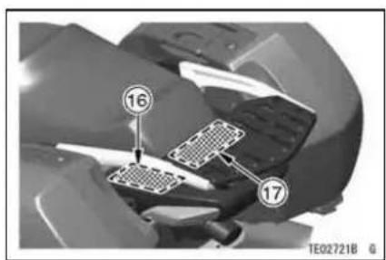
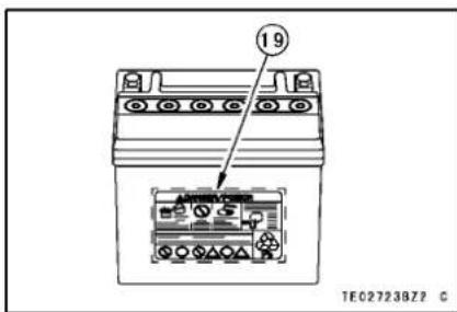
natural_image
Close-up of a mechanical component with a grid-patterned inset and numbered annotation (18), no readable text or symbols present.- Saddlebag Load Warning
- Rear Carrier Notice
- FOB Storage Notice
- Battery Position/Danger
LOCATION OF LABELS
1)

2)

3)

56053-0461
TE03366C S
274 LOCATION OF LABELS
4) (ZG1400C)
| VEHICLE EMISSION CONTROL INFORMATION | |
| ENGINE FAMILY CODE --- AKAXC1.35AAD PERMEATION FAMILY --- AKAXPNETAL01 | |
| MODEL(S) --- Z61400CA | |
| EXHAUST EMISSION CONTROL SYSTEM --- SFI+PAIR+20C | |
| DISPLACEMENT --- 1352 CC | |
| TUNE UP SPECIFICATIONS | |
| IGNITION TIMING | 10° BTDC AT 1100 RPM |
| IDLE SPEED | 1100 ± 50 RPM IN NEUTRAL |
| IDLE AIR FUEL MIXTURE SETTING | NO ADJUSTMENT |
| VALVE CLEARANCE (ENGINE COLD) | INTAKE : 0.12-0.17 MM [0.0047-0.0067 IN] EXHAUST : 0.19-0.24 MM [0.0075-0.0094 IN] |
| SPARK PLUG | CR9EIA-9 (NGK) SPARK PLUG GAP : 0.8-0.9 MM (0.032-0.036 IN) |
| FUEL | GASOLINE WITH ANTIKNOCK INDEX (RON+MON)/2 90 MIN. |
| ENGINE OIL | SERVICE RATING : (API) SG, SH, SJ, SL OR SM WITH JASO MA VISCOSITY : SAE 10W-40 SEE THE OWNER'S MANUAL FOR ENGINE OIL INFORMATION. |
| THIS VEHICLE CONFORMS TO U.S.EPA REGULATIONS APPLICABLE TO 2010 MODEL YEAR NEW MOTORCYCLES AND IS CERTIFIED TO AN HC+NOX EMISSION STANDARD OF 0.86/KM.KAMASAKI HEAVY INDUSTRIES, LTD. | |
59464-1869
TE03389CZ9 C
4) (ZG1400C) only on California model
| VEHICLE EMISSION CONTROL INFORMATION | |
| ENGINE FAMILY CODE --- AKAXC1 35AAD PERMEATION FAMILY --- AKAXPMETAL01 | |
| EVAP. FAMILY ---AKAXU17.0A02 | |
| MODEL(S) ---ZG1400CA | |
| EXHAUST EMISSION CONTROL SYSTEM --- SFI+PAIR+20C | |
| DISPLACEMENT ---1352 CC | |
| TUNE UP SPECIFICATIONS | |
| IGNITION TIMING | 10" BTDC AT :100 RPM |
| IDLE SPEED | 1100 ± 50 RPM IN NEUTRAL |
| IDLE AIR FUEL MIXTURE SETTING | NO ADJUSTMENT |
| VALVE CLEARANCE (ENGINE COLD) | INTAKE : 0.12-0.17 MM (0.0047-0.0087 IN)EXHAUST : 0.19-0.24 MM (0.0075-0.0094 IN) |
| SPARK PLUG | CRSEIA-9 (NGK) SPARK PLUG GAP : 0.8-0.9 MM(0.032-0.036 IN) |
| FUEL | GASOLINE WITH ANTIKNOCK INDEX (RON+MON)/2 90 MIN. |
| ENGINE OIL | SERVICE RATING : (API) SG, SH, SJ, SL OR SMWITH JASO MAVISCOSITY :SAE 10W-40SEE THE OWNER'S MANUAL FOR ENGINE OIL INFORMATION. |
| THIS VEHICLE CONFORMS TO U.S.EPA AND CALIFORNIA REGULATIONS APPLICABLE TO 2010 MODEL YEAR NEW MOTORCYCLES AND IS CERTIFIED TO 0.8G/KM HC+NOX ENGINE FAMILY EXHAUST EMISSION STANDARD IN CALIFORNIA.KAWASAKI HEAVY INDUSTRIES, LTD. | |
59464-1873
TE03402CZ9 C
276 LOCATION OF LABELS
4) (ZG1400D)
| VEHICLE EMISSION CONTROL INFORMATION | |
| ENGINE FAMILY CODE --- AKAXG1.35AAD PERMEATION FAMILY --- AKAXPNETAL01 | |
| MODEL(S) --- ZG1400DA | |
| EXHAUST EMISSION CONTROL SYSTEM --- SFI+PAIR+20C | |
| DISPLACEMENT --- 1352 CC | |
| TUNE UP SPECIFICATIONS | |
| IGNITION TIMING | 10° BTDC AT 1100 RPM |
| IDLE SPEED | 1100 ± 50 RPM IN NEUTRAL |
| IDLE AIR FUEL MIXTURE SETTING | NO ADJUSTMENT |
| VALVE CLEARANCE (ENGINE COLD) | INTAKE : 0.12-0.17 MM [0.0047-0.0067 IN] EXHAUST : 0.19-0.24 MM [0.0075-0.0094 IN] |
| SPARK PLUG | CR9EIA-9 (NGK) SPARK PLUG GAP : 0.8-0.9 MM (0.032-0.036 IN) |
| FUEL | GASOLINE WITH ANTIKNOCK INDEX (RON+MON)/2 90 MIN. |
| ENGINE OIL | SERVICE RATING : (API) SG, SH, SJ, SL OR SM WITH JASO MA VISQOSITY : SAE 10W-40 SEE THE OWNER'S MANUAL FOR ENGINE OIL INFORMATION. |
| THIS VEHICLE CONFORMS TO U.S.EPA REGULATIONS APPLICABLE TO 2010 MODEL YEAR NEW MOTORCYCLES AND IS CERTIFIED TO AN HC+NOX EMISSION STANDARD OF 0.86/KM.KAMASAKI HEAVY INDUSTRIES, LTD. | |
59464-1870
TE03393CZ9 C
4) (ZG1400D) only on California model
| VEHICLE EMISSION CONTROL INFORMATION | |
| ENGINE FAMILY CODE --- AKAXC1 35AAD PERMEATION FAMILY ---- AKAXPMETAL01 | |
| EVAP. FAMILY ---- AKAXU17.0AD2 | |
| MODEL(S) ---- 2G1400DA | |
| EXHAUST EMISSION CONTROL SYSTEM ---- SFI+PAIR+20C | |
| DISPLACEMENT ---- 1352 CC | |
| TUNE UP SPECIFICATIONS | |
| IGNITION TIMING | 10" BTDC AT 1100 RPM |
| IDLE SPEED | 1100 ± 50 RPM IN NEUTRAL |
| IDLE AIR FUEL MIXTURE SETTING | NO ADJUSTMENT |
| VALVE CLEARANCE (ENGINE COLD) | INTAKE : 0.12-0.17 MM (0.0047-0.0067 IN) EXHAUST : 0.19-0.24 MM (0.0075-0.0094 IN) |
| SPARK PLUG | CRSEIA-9 (NGK) SPARK PLUG GAP : 0.8-0.9 MM (0.032-0.036 IN) |
| FUEL | GASOLINE WITH ANTIKNOCK INDEX (RON-MON)/2 90MIN. |
| ENGINE OIL | SERVICE RATING : (API) SG, SH, SJ, SL OR SM WITH JASO MA VISCOSITY:SAE 10W-40 SEE THE OWNER'S MANUAL FOR ENGINE OIL INFORMATION. |
| THIS VEHICLE CONFORMS TO U.S.EPA AND CALIFORNIA REGULATIONS APPLICABLE TO 2010 MODEL YEAR MEN MOTORCYCLES AND IS CERTIFIED TO 0.8G/KM HC+NOX ENGINE FAMILY EXHAUST EMISSION STANDARD IN CALIFORNIA. KAWASAKI HEAVY INDUSTRIES, LTD. | |
59464-1874
TE03403CZ9 C
278 LOCATION OF LABELS
5)

7) (ZG1400C)

6) only on California model

7) (ZG1400D)

8) (ZG1400C)
MOTORCYCLE NOISE EMISSION CONTROL INF. THIS 2010 MOTORCYCLE MEETS EPA NOISE EMISSION REQUIREMENTS BY THE FEDERAL TEST PROCEDURE. MODIFICATIONS WHICH CAUSE THIS MOTORCYCLE TO EXCEED FEDERAL NOISE STANDARDS ARE PROHIBITED BY FEDERAL LAW. SEE OWNER'S MANUAL. (ZG1400C) MODEL SPECIFIC CODE: KAM6051400 SEE VEHICLE IDENTIFICATION NUMBER ON STEERING HEAD NOISE LIMIT/CLOSING RPM: 80D8A/4840RPM
59464-1875 TE03398CN9
8) (ZG1400D)
MOTORCYCLE NOISE EMISSION CONTROL INF. THIS 2010 MOTORCYCLE WEETS EPA NOISE EMISSION REQUIREMENTS BY THE FEDERAL TEST PROCEDURE. MODIFICATIONS WHICH CAUSE THIS MOTORCYCLE TO EXCEED FEDERAL NOISE STANDARDS ARE PROHIBITED BY FEDERAL LAW. SEE OWNER'S MANUAL. (201400D) MODEL SPECIFIC CODE: KANG051400 SEE VEHICLE IDENTIFICATION NUMBER ON STEERING HEAD NOISE LIMIT/CLOSING RPM: 80DBA/4840RPM
59464-1876 TE03400CN9 C
LOCATION OF LABELS 279
9) only on California model

flowchart
graph TD
    A["FUEL TANK"] --> B["AIR CLEANER"]
    B --> C["CONNECT TO #3"]
    B --> D["CONNECT TO #4"]
    B --> E["GREEN (PURGE)"]
    B --> F["INJECTOR THROTTLE"]
    F --> G["BLUE"]
    G --> H["RETURN PUMP"]
    H --> I["CANISTER"]
    I --> J["WHITE(CONNECT TO #3)"]
    style A fill:#f9f,stroke:#333
    style J fill:#ccf,stroke:#333
TE03466BN7 C
280 LOCATION OF LABELS
10)
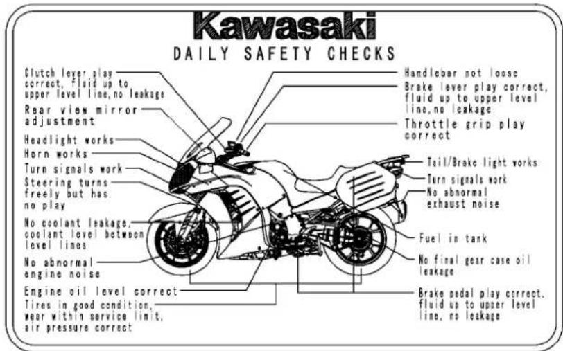
56033-0326
TE03356CZ9 C
11)
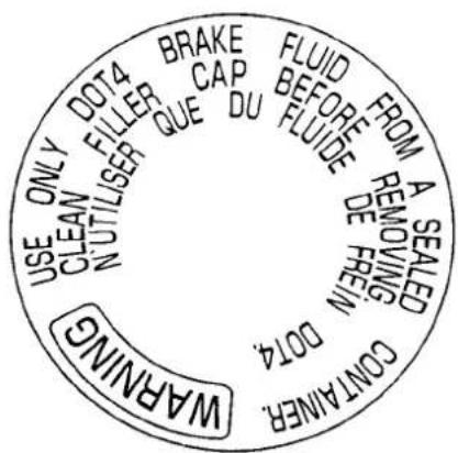
LOCATION OF LABELS
12)
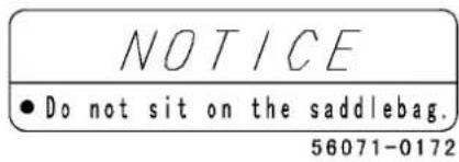
TE03377CN9 C
13)

TE03097B 5
282 LOCATION OF LABELS
14)
| DO NOT EXCEEDMAXIMUM LOAD | EACHSADDLEBAG |
| 10 kg(22 lbs) |
TE03682BN9 C
15)
| NOTICE |
| Do not put load on the lid. |
| Do not sit on the lid. |
16)
| WARNING |
| Improper loading way cause loss of control resulting in an accident leading to serious injury or death. |
| Read your Owner's Manual for more detailed and complete instruction. |
7)
| DO NOT EXCEEDMAXIMUM LOAD | REARCARRIER |
| 10 kg(22 lbs) |
LOCATION OF LABELS 283
18)

TE03397CN9 C
284 LOCATION OF LABELS
19)
⚠️ DANGER/POISON

EYES
EXPLOSIVE GASES CAN CAUSE BLINDNESS OR INJURY

NO ·SPARKS ·FLAMES ·SMOKING

SULFURIC ACID CAN CAUSE BLINDNESS OR SEVERE BURNS
FLUSH EYES IMMEDIATELY WITH WATER
KEEP OUT OF REACH OF CHILDREN


IN U.S.A., DISTR. BY KAWASAKI MOTORS CORP. SANTA ANA, CA. 92799-5252

RECYCLE
ZG1400CA/DA

Kawasaki
KAWASAKI HEAVY INDUSTRIES, LTD. Consumer Products & Machinery Company
Part No. 99987-1608
Printed in Japan
- Kawasaki
- Includes:
- WARNING
- NOTICE
- Quick Reference Guide
- ! DANGER
- CAUTION
- NOTE
- FOREWORD
- KAWASAKI HEAVY INDUSTRIES, LTD. Consumer Products & Machinery Company
- TABLE OF CONTENTS
- SPECIFICATIONS
- SPECIFICATIONS
- TRANSMISSION
- SPECIFICATIONS 11
- SPECIFICATIONS
- SERIAL NUMBER LOCATIONS
- LOCATION OF PARTS
- LOCATION OF PARTS
- LOADING AND ACCESSORIES INFORMATION
- LOADING AND ACCESSORIES INFORMATION
- LOADING AND ACCESSORIES INFORMATION
- Maximum Load
- GENERAL INFORMATION
- Meter Instruments
- GENERAL INFORMATION
- Speedometer and Tachometer
- GENERAL INFORMATION 23
- Multifunction Meter
- GENERAL INFORMATION
- GENERAL INFORMATION 25
- Odometer/Trip Meters -
- "ODO"/"TRIP A"/"TRIP B"
- GENERAL INFORMATION 27
- To reset the trip meter:
- GENERAL INFORMATION
- Clock -
- Mileage (Average Mileage/Current Mileage/Cruising Range) -
- "AVERAGE"
- GENERAL INFORMATION 29
- GENERAL INFORMATION
- "CURRENT"
- GENERAL INFORMATION 31
- "RANGE"
- GENERAL INFORMATION
- GENERAL INFORMATION
- Tire Air Pressure -
- "TIRE F/R"
- GENERAL INFORMATION 35
- Battery Voltage -
- "BATTERY"
- GENERAL INFORMATION
- Outside Temperature -
- Gear Position -
- GENERAL INFORMATION 37
- GENERAL INFORMATION
- Coolant Temperature Gauge -
- GENERAL INFORMATION
- Fuel Gauge -
- GENERAL INFORMATION
- K-ACT ABS Standard Mode (mode 1)/High Combined Mode (mode 2) for models equipped with K-ACT ABS -
- GENERAL INFORMATION 43
- GENERAL INFORMATION
- Economical Riding Indicator and Fuel Economy Assistance Mode -
- Economical Riding Indicator
- Fuel Economy Assistance Mode
- GENERAL INFORMATION 45
- GENERAL INFORMATION
- Language Setting: ENGLISH/FRANCAIS/DEUTSCH/ITALIANO -
- GENERAL INFORMATION
- Unit Setting: KPA, PSI -
- "TIRE PRESSURE"
- "MILEAGE"
- GENERAL INFORMATION
- Unit Setting: °C, °F -
- "OUTSIDE TEMP"
- GENERAL INFORMATION 51
- GENERAL INFORMATION
- Electric Windshield -
- "WINDSHIELD SET"
- GENERAL INFORMATION 53
- Push Lower Button
- GENERAL INFORMATION
- "CLOCK"
- GENERAL INFORMATION 55
- Warning/Indicator Lights
- GENERAL INFORMATION
- (For models equipped with K-ACT ABS)
- (For models equipped with KTRC)
- GENERAL INFORMATION 57
- GENERAL INFORMATION
- FI Warning Message/FI Warning Symbol -
- GENERAL INFORMATION
- GENERAL INFORMATION 61
- Immobilizer Warning Message/Warning Symbol -
- Steering Lock Warning Message/Warning Symbol -
- GENERAL INFORMATION
- GENERAL INFORMATION 65
- Tire Air Pressure Sensor Warning Message/Warning Symbol -
- GENERAL INFORMATION
- Tire Air Pressure Warning Message/Warning Symbol -
- GENERAL INFORMATION
- GENERAL INFORMATION 71
- GENERAL INFORMATION
- GENERAL INFORMATION 73
- FOB Warning Message/Warning Symbol -
- GENERAL INFORMATION
- GENERAL INFORMATION 75
- GENERAL INFORMATION
- GENERAL INFORMATION 79
- KIPASS (Kawasaki's Intelligent Proximity Activation Start System) System
- GENERAL INFORMATION
- Starting the engine -
- GENERAL INFORMATION 81
- FOB (Portable Key) -
- GENERAL INFORMATION
- GENERAL INFORMATION 83
- Battery Replacement
- GENERAL INFORMATION 85
- GENERAL INFORMATION
- GENERAL INFORMATION 87
- GENERAL INFORMATION
- GENERAL INFORMATION 89
- FOB Possible Radio Wave Area -
- GENERAL INFORMATION
- KIPASS System Does Not Operate -
- Special Warning on KIPASS System
- GENERAL INFORMATION
- Spare FOB
- Spare FOB
- Emergency Ignition Key (Mechanical Key)
- GENERAL INFORMATION
- GENERAL INFORMATION 95
- Ignition Switch
- GENERAL INFORMATION
- GENERAL INFORMATION 99
- GENERAL INFORMATION
- GENERAL INFORMATION
- Left Handlebar Switches
- Dimmer Switch
- Turn Signal Switch
- Horn Button
- GENERAL INFORMATION 103
- Meter Mode Button
- K-ACT ABS Button (only on equipped models)
- KTRC Button (only on equipped models)
- Electric Windshield Adjusting Button
- GENERAL INFORMATION
- Engine Stop Switch
- Starter Button
- Hazard Switch
- GENERAL INFORMATION
- Grip Warmer
- GENERAL INFORMATION
- Battery Protection -
- Headlight Aiming Adjuster Knob
- Accessory Socket/Connectors
- GENERAL INFORMATION
- GENERAL INFORMATION
- Brake/Clutch Lever Adjuster
- Fuel Tank Cap
- GENERAL INFORMATION
- Fuel Tank
- Fuel Requirement
- Stands
- GENERAL INFORMATION 119
- GENERAL INFORMATION
- Seat
- Seat Removal
- Seat Installation
- GENERAL INFORMATION
- Special Warning on the Use of Storage Case and Saddlebags (Accessory)
- Saddlebags (Accessory)
- To open the saddlebag lid -
- To close the saddlebag lid -
- GENERAL INFORMATION
- To remove the saddlebag -
- To install the saddlebag -
- GENERAL INFORMATION
- Storage Case
- Electric Lock -
- GENERAL INFORMATION 131
- GENERAL INFORMATION
- Rear Carrier
- GENERAL INFORMATION
- Tool Kit Compartment
- Air Intake
- BREAK-IN
- BREAK-IN
- HOW TO RIDE THE MOTORCYCLE
- Starting the Engine
- HOW TO RIDE THE MOTORCYCLE
- Jump Starting
- DANGER
- HOW TO RIDE THE MOTORCYCLE
- Moving Off
- HOW TO RIDE THE MOTORCYCLE 143
- Shifting Gears
- HOW TO RIDE THE MOTORCYCLE
- HOW TO RIDE THE MOTORCYCLE 145
- Braking
- HOW TO RIDE THE MOTORCYCLE
- Kawasaki Advanced Coactive-braking Technology (K-ACT) - Anti-lock Brake System (ABS) for models equipped with K-ACT ABS
- HOW TO RIDE THE MOTORCYCLE
- K-ACT ABS Indicator Light
- HOW TO RIDE THE MOTORCYCLE 149
- HOW TO RIDE THE MOTORCYCLE
- Stopping the Engine
- HOW TO RIDE THE MOTORCYCLE 151
- Stopping the Motorcycle in an Emergency
- HOW TO RIDE THE MOTORCYCLE
- Parking
- HOW TO RIDE THE MOTORCYCLE
- Catalytic Converter
- HOW TO RIDE THE MOTORCYCLE 155
- HOW TO RIDE THE MOTORCYCLE
- Kawasaki TRaction Control (KTRC) for models equipped with KTRC
- KTRC Indicator Light
- Operation -
- HOW TO RIDE THE MOTORCYCLE
- Self-diagnosis Uncompleted -
- HOW TO RIDE THE MOTORCYCLE 159
- KTRC Malfunction -
- HOW TO RIDE THE MOTORCYCLE
- KTRC Button
- To set the KTRC -
- HOW TO RIDE THE MOTORCYCLE 161
- Safe Riding Technique
- SAFE OPERATION
- Daily Safety Checks
- SAFE OPERATION
- SAFE OPERATION
- Additional Considerations for High Speed Operation
- MAINTENANCE AND ADJUSTMENT
- MAINTENANCE AND ADJUSTMENT
- EMISSION CONTROL INFORMATION
- Crankcase Emission Control System
- Exhaust Emission Control System
- MAINTENANCE AND ADJUSTMENT
- Evaporative Emission Control System
- Evaporative Emission Control System (California)
- High Altitude Performance Adjustment Information
- MAINTENANCE AND WARRANTY
- MAINTENANCE AND ADJUSTMENT
- TAMPERING WITH NOISE CONTROL SYSTEM PROHIBITED:
- Periodic Maintenance Chart
- MAINTENANCE AND ADJUSTMENT
- : Service more frequently when operating in severe conditions: dusty, wet, muddy, high speed, or frequent starting/stopping.
- Engine Oil
- Oil Level Inspection
- MAINTENANCE AND ADJUSTMENT
- Oil and/or Oil Filter Change
- MAINTENANCE AND ADJUSTMENT 189
- MAINTENANCE AND ADJUSTMENT
- Tightening Torque
- Recommended Engine Oil
- Engine Oil Capacity
- MAINTENANCE AND ADJUSTMENT
- Final Gear Case Oil
- MAINTENANCE AND ADJUSTMENT 193
- MAINTENANCE AND ADJUSTMENT
- Cooling System
- Radiator and Cooling Fan -
- MAINTENANCE AND ADJUSTMENT
- Radiator Hoses -
- Coolant -
- Information for Coolant
- MAINTENANCE AND ADJUSTMENT
- MAINTENANCE AND ADJUSTMENT 199
- MAINTENANCE AND ADJUSTMENT
- Coolant Change
- Spark Plugs
- MAINTENANCE AND ADJUSTMENT 201
- Evaporative Emission Control System (California model only)
- Inspection
- MAINTENANCE AND ADJUSTMENT
- Valve Clearance
- MAINTENANCE AND ADJUSTMENT 203
- Kawasaki Clean Air System
- Air Suction Valves -
- MAINTENANCE AND ADJUSTMENT
- Air Cleaner
- Air Cleaner Element Removal
- MAINTENANCE AND ADJUSTMENT 205
- MAINTENANCE AND ADJUSTMENT
- MAINTENANCE AND ADJUSTMENT
- MAINTENANCE AND ADJUSTMENT 209
- MAINTENANCE AND ADJUSTMENT
- Oil Draining
- Reservoir
- Throttle Control System
- Throttle Grip -
- Throttle Grip Play
- Adjustment
- MAINTENANCE AND ADJUSTMENT
- MAINTENANCE AND ADJUSTMENT 213
- Engine Vacuum Synchronization
- MAINTENANCE AND ADJUSTMENT
- Idle Speed
- Idle Adjusting Screw
- MAINTENANCE AND ADJUSTMENT 215
- Clutch
- Clutch Operation Inspect
- MAINTENANCE AND ADJUSTMENT
- Fluid Level Inspection
- Brakes
- Brake Wear Inspection
- Disc Brake Fluid -
- Fluid Requirement
- MAINTENANCE AND ADJUSTMENT
- Front and Rear Brakes -
- MAINTENANCE AND ADJUSTMENT
- Brake Light Switches
- MAINTENANCE AND ADJUSTMENT
- Front Fork
- Front Fork Inspection
- MAINTENANCE AND ADJUSTMENT
- Spring Preload Adjustment
- Adjusting Range
- MAINTENANCE AND ADJUSTMENT 225
- MAINTENANCE AND ADJUSTMENT
- Rear Shock Absorber
- MAINTENANCE AND ADJUSTMENT
- Rebound Damping Force Adjuster
- Wheels
- MAINTENANCE AND ADJUSTMENT 229
- MAINTENANCE AND ADJUSTMENT
- Tire Sealants
- Tires -
- Payload and Tire Pressure
- Tire Pressure Gauge
- Tire Wear, Damage
- MAINTENANCE AND ADJUSTMENT
- MAINTENANCE AND ADJUSTMENT
- Battery
- Battery Sulfation -
- Battery Maintenance -
- Kawasaki-recommended chargers are:
- Battery Charging -
- MAINTENANCE AND ADJUSTMENT
- Battery Removal
- MAINTENANCE AND ADJUSTMENT 239
- MAINTENANCE AND ADJUSTMENT
- Battery Installation
- MAINTENANCE AND ADJUSTMENT 241
- MAINTENANCE AND ADJUSTMENT
- MAINTENANCE AND ADJUSTMENT 243
- Headlight Beam
- Fuses
- MAINTENANCE AND ADJUSTMENT
- MAINTENANCE AND ADJUSTMENT 247
- General Lubrication
- MAINTENANCE AND ADJUSTMENT
- Apply grease to the following points -
- Cleaning Your Motorcycle
- MAINTENANCE AND ADJUSTMENT 249
- MAINTENANCE AND ADJUSTMENT
- MAINTENANCE AND ADJUSTMENT 251
- MAINTENANCE AND ADJUSTMENT
- Chrome and Aluminum
- Leather, Vinyl, and Rubber
- MAINTENANCE AND ADJUSTMENT
- Bolt and Nut Tightening
- MAINTENANCE AND ADJUSTMENT
- STORAGE
- Preparation for Storage
- STORAGE
- STORAGE 259
- Preparation after Storage
- TROUBLESHOOTING GUIDE
- Engine Does Not Start -
- Engine Stalls -
- OWNER SATISFACTION
- (For Products Sold in the Continental United States of America Only)
- OWNER SATISFACTION
- REPORTING SAFETY DEFECTS
- ENVIRONMENTAL PROTECTION
- ENVIRONMENTAL PROTECTION
- MAINTENANCE RECORD
- LOCATION OF LABELS
- LOCATION OF LABELS
- LOCATION OF LABELS
- 4) (ZG1400C)
- 4) (ZG1400C) only on California model
- LOCATION OF LABELS
- 4) (ZG1400D)
- 4) (ZG1400D) only on California model
- LOCATION OF LABELS
- 8) (ZG1400C)
- 8) (ZG1400D)
- LOCATION OF LABELS 279
- 9) only on California model
- LOCATION OF LABELS
- LOCATION OF LABELS
- ⚠️ DANGER/POISON
- KEEP OUT OF REACH OF CHILDREN
- ZG1400CA/DA
Marque : KAWASAKI
Modèle : Concours 14 (2009)
Catégorie : Moto