
KZ440 (1981) - Moto KAWASAKI - Notice d'utilisation et mode d'emploi gratuit
Retrouvez gratuitement la notice de l'appareil KZ440 (1981) KAWASAKI au format PDF.


| Type de produit | Moto |
| Marque | Kawasaki |
| Modèle | KZ440 (1981) |
| Catégorie | Moto |
| Moteur | Bicylindre parallèle, 440 cm³, refroidi par air, 4 temps |
| Puissance | Environ 30-35 ch (estimé) |
| Transmission | Manuelle 5 vitesses |
| Alimentation en carburant | Essence sans plomb, réservoir environ 13 L |
| Démarrage | Électrique et kick |
| Frein avant | Disque unique |
| Frein arrière | Tambour |
| Poids à sec | Environ 180 kg |
| Suspension avant | Fourche télescopique |
| Suspension arrière | Amortisseurs doubles réglables |
| Pneus avant | 3.00-18 (taille typique) |
| Pneus arrière | 3.50-16 (taille typique) |
| Capacité d'huile moteur | Environ 1,7 L avec filtre |
| Batterie | 12V, type plomb-acide |
| Entretien courant | Vidange, filtre à huile, bougies, réglage chaîne |
| Nettoyage | Eau savonneuse, éviter haute pression sur le moteur |
FOIRE AUX QUESTIONS - KZ440 (1981) KAWASAKI
Questions des utilisateurs sur KZ440 (1981) KAWASAKI
0 question sur cet appareil. Repondez a celles que vous connaissez ou posez la votre.
Poser une nouvelle question sur cet appareil
Téléchargez la notice de votre Moto au format PDF gratuitement ! Retrouvez votre notice KZ440 (1981) - KAWASAKI et reprennez votre appareil électronique en main. Sur cette page sont publiés tous les documents nécessaires à l'utilisation de votre appareil KZ440 (1981) de la marque KAWASAKI.
MODE D'EMPLOI KZ440 (1981) KAWASAKI
B3
Kawasaki
KZ440

Motorcycle Service Manual
Decimal Equivalents
| INCH | MM INCH | INCH | MM INCH | ||||||||
| 1/64 | .015625 | 1mm=.03937 inch | 33/64 | .515625 | 14mm=.55118 inch | ||||||
| 1/32 | .03125 | 17/32 | .53125 | ||||||||
| 3/64 | .046875 | 35/64 | .546875 | ||||||||
| 1/16 | .0625 | 9/16 | .5625 | ||||||||
| 5/64 | .078125 | 2mm=.07874 inch | 37/64 | .578125 | 15mm=.59055 inch | ||||||
| 3/32 | .09375 | 19/32 | .59375 | ||||||||
| 7/64 | .109375 | 3mm=.11811 inch | 39/64 | .609375 | 16mm=.62992 inch | ||||||
| 1/8 | .125 | 5/8 | .625 | ||||||||
| 9/64 | .140625 | 4mm=.15748 inch | 41/64 | .640625 | |||||||
| 5/32 | .15625 | 21/32 | .65625 | 17mm=.66929 inch | |||||||
| 11/64 | .171875 | 43/64 | .671875 | ||||||||
| 3/16 | .1875 | 5mm=.19685 inch | 11/16 | .6875 | 18mm=.70866 inch | ||||||
| 13/64 | .203125 | 45/64 | .703125 | ||||||||
| 7/32 | .21875 | 23/32 | .71875 | ||||||||
| 15/64 | .234375 | 6mm=.23622 inch | 47/64 | .734375 | 19mm=.74803 inch | ||||||
| 1/4 | .25 | 3/4 | .75 | ||||||||
| 17/64 | .265625 | 7mm=.27559 inch | 49/64 | .765625 | 20mm=.78740 inch | ||||||
| 9/32 | .28125 | 25/32 | .78125 | ||||||||
| 19/64 | .296875 | 51/64 | .796875 | ||||||||
| 5/16 | .3125 | 8mm=.31496 inch | 13/16 | .8125 | 21mm=.82677 inch | ||||||
| 21/64 | .328125 | 53/64 | .828125 | ||||||||
| 11/32 | .34375 | 9mm=.35433 inch | 27/32 | .84375 | 22mm=.86614 inch | ||||||
| 23/64 | .359375 | 55/64 | .859375 | ||||||||
| 3/8 | .375 | 7/8 | .875 | ||||||||
| 25/64 | .390625 | 10mm=.39370 inch | 57/64 | .890625 | 23mm=.90551 inch | ||||||
| 13/32 | .40625 | 29/32 | .90625 | ||||||||
| 27/64 | .421875 | 11mm=.43307 inch | 59/64 | .921875 | 24mm=.94488 inch | ||||||
| 7/16 | .4375 | 15/16 | .9375 | ||||||||
| 29/64 | .453125 | 61/64 | .953125 | ||||||||
| 15/32 | .46875 | 12mm=.47244 inch | 31/32 | .96875 | 25mm=.98425 inch | ||||||
| 31/64 | .484375 | 13mm=.51181 inch | 63/64 | .984375 | |||||||
| 1/2 | .5 | 1 | 1. | ||||||||
Unit Conversion Table
| cc | x | .0610 | = cu in |
| cc | x | .02816 | = oz (imp) |
| cc | x | .03381 | = oz (US) |
| cu in | x | 16.39 | = cc |
| ft-lbs | x | 12 | = in lbs |
| ft-lbs | x | .1383 | = kg-m |
| gal (imp) | x | 4.546 | = litres |
| gal (imp) | x | 1.201 | = gal (US) |
| gal (US) | x | 3.7853 | = liters |
| gal (US) | x | .8326 | = gal (Imp) |
| grams | x | .03527 | = oz |
| in | x | 25.40 | = mm |
| in lbs | x | .0833 | = ft-lbs |
| in lbs | x | .0115 | = kg-m |
| kg | x | 2.2046 | = lbs |
| kg | x | 35.274 | = oz |
| kg-m | x | 7.233 | = ft-lbs |
| kg-m | x | 86.796 | = in-lbs |
| kg/cm2 | x | 14.22 | = lbs/in2 |
| km | x | .6214 | = mile |
| lb | x | .4536 | = kg |
| lb/in2 | x | .0703 | = kg/cm2 |
| litre | x | 28.16 | = oz (imp) |
| litre | x | 33.81 | = oz (US) |
| litre | x | .8799 | = qt (imp) |
| litre | x | 1.0567 | = qt (US) |
| metre | x | 3.281 | = ft |
| mile | x | 1.6093 | = km |
| mm | x | .03937 | = in |
| oz (imp) | x | 35.51 | = cc |
| oz (US) | x | 29.57 | = cc |
| oz (weight) | x | 28.35 | = grams |
| qt (imp) | x | 1.1365 | = litre |
| qt (imp) | x | 1.201 | = qt (US) |
| qt (US) | x | .9463 | = litre |
| qt (US) | x | .8326 | = qt (imp) |
| kg/cm2 | x | 98.07 | = kPa |
| lbs/in2 | x | 6.896 | = kPa |
| kPa | x | .1450 | = lbs/in2 |
List of Abbreviations
| ABDC | after bottom dead center |
| ATDC | after top dead center |
| BBDC | before bottom dead center |
| BDC | bottom dead center |
| BTDC | before top dead center |
| cc | cubic centimeters |
| cu in | cubic inches |
| ft | foot, feet |
| ft-lbs | foot-pounds |
| gal | gallon, gallons |
| hp | horsepower |
| in | inch, inches |
| in-lb | inch-pounds |
| kg | kilogram, kilograms |
| kg/cm2 | kilograms per square centimeter |
| kg-m | kilogram meters |
| km | kilometer |
| kph | kilometers per hour |
| lb, lbs | pound, pounds |
| lbs/in2 | pounds per square inch |
| ltr | liter, litre |
| m | meter, meters |
| mi | mile, miles |
| mm | milimeters |
| mph | miles per hour |
| oz | ounce, ounces |
| psi | pounds per square inch |
| qt | quart, quarts |
| rpm | revolutions per minute |
| sec | second, seconds |
| SS | standing start |
| TDC | top dead center |
| " | inch, inches |
| r/min | revolutions per minute |
| l | liter, litre |
| kPa | kilo-Pascals |
[Non-Text]
Kawasaki KZ440

Motorcycle Service Manual
EMISSION CONTROL INFORMATION
To protect the environment in which we all live, Kawasaki has incorporated two emission control systems in compliance with the applicable regulations of the United States Environmental Protection Agency.
- Crankcase Emission Control System
This system eliminates the release of crankcase vapors into the atmosphere. Instead, the vapors are routed through an oil separator to the intake side of the engine. While the engine is operating, the vapors are drawn into the combustion chamber, where they are burned along with the fuel and air supplied by the carburetors.
- Exhaust Emission Control System
This system reduces the amount of pollutants discharged into the atmosphere by the exhaust of this motorcycle. The fuel and ignition systems of this motorcycle have been carefully designed and constructed to ensure an efficient engine with low exhaust pollutant levels.
The Clean Air Act, which is the Federal law covering motor vehicle pollution, contains what is commonly referred to as the Act's "tampering provisions".
"Sec. 203(a) The following acts and the causing thereof are prohibited...
(3)(A) for any person to remove or render inoperative any device or element of design installed on or in a motor vehicle or motor vehicle engine in compliance with regulations under this title prior to its sale and delivery to the ultimate purchaser, or for any manufacturer or dealer knowingly to remove or render inoperative any such device or element of design after such sale and delivery to the ultimate purchaser.
(3)(B) for any person engaged in the business of repairing, servicing, selling, leasing, or trading motor vehicles or motor vehicle engines, or who operates a fleet of motor vehicles knowingly to remove or render inoperative any device or element of design installed on or in a motor vehicle or motor vehicle engine in compliance with regulations under this title following its sale and delivery to the ultimate purchaser...”
Note: The phrase "remove or render inoperative any device or element of design" has been generally interpreted as follows:
- Tampering does not include the temporary removal or rendering inoperative of devices or elements of design in order to perform maintenance.
EMISSION CONTROL INFORMATION (CONT.)
- Tampering could include:
a. Maladjustment of vehicle components such that the emission standards are exceeded.
b. Use of replacement parts or accessories which adversely affect the performance or durability of the motorcycle.
c. Addition of components or accessories that result in the vehicle exceeding the standards.
d. Permanently removing, disconnecting, or rendering inoperative any component or element of design of the emission control systems.
WE RECOMMEND THAT ALL DEALERS OBSERVE THESE PROVISIONS OF FEDERAL LAW, THE VIOLATION OF WHICH IS PUNISHABLE BY CIVIL PENALTIES NOT EXCEEDING \$10,000 PER VIOLATION.
Foreword
This manual is designed primarily for use by motorcycle mechanics in a properly equipped shop, although it contains enough detail and basic information to make it useful to the motorcycle user who desires to carry out his own basic maintenance and repair work. Since a certain basic knowledge of mechanics, the proper use of tools, and workshop procedures must be understood in order to carry out maintenance and repair satisfactorily; the adjustments, maintenance, and repair should be carried out only by qualified mechanics whenever the owner has insufficient experience, or has doubts as to his ability to do the work, so that the motorcycle can be operated safely.
In order to perform the work efficiently and to avoid costly mistakes, the mechanic should read the text, thoroughly familiarizing himself with the procedures before starting work, and then do the work carefully in a clean area. Whenever special tools or equipment is specified, makeshift tools or equipment should not be used. Precision measurements can only be made if the proper instruments are used, and the use of substitute tools may adversely affect safe operation of the motorcycle.
Whenever you see the symbols shown below, heed their instructions! Always follow safe operating and maintenance practices.
WARNING
This warning symbol identifies special instructions or procedures which, if not correctly followed, could result in personal injury, or loss of life.
CAUTION
This caution symbol identifies special instructions or procedures which, if not strictly observed, could result in damage to, or destruction of equipment.
"NOTE" indicates points of particular interest for more efficient and convenient operation.
This manual is divided into the following chapters:
(1) Adjustment
The adjustment chapter gives the procedure for all adjustments which may become necessary periodically and which do not involve major disassembly.
(2) Disassembly
This chapter shows the best method for the removal, disassembly, assembly, and installation which are necessary for maintenance and repair. Do not disassemble the component parts further than explained here. Since assembly and installation are usually the reverse of disassembly and removal, assembly and installation are not explained in detail in some cases. Instead, assembly notes and installation notes are provided to explain special points.
In cases the removal procedures are apparent without explanation such as for the seat or side stand, no information is given.
(3) Maintenance and theory of Operation
The procedures for inspection and repair are described in detail in this chapter. An explanation on the structure and functioning of each of the major parts and assemblies, especially on one of new devices, is given to enable the mechanic to better understand what he is doing.
(4) Appendix
The appendix in the back of this manual contains miscellaneous information, including a special tool list and wiring diagram.
(5) Supplement
The maintenance and repair procedures, that unique to later year units since the first publication of the Service Manual, are explained in this chapter per one year unit.
Since the Service Manual is based on the first production unit of the 1980 KZ440-A1, B1, C1, D1, there may be minor discrepancies between some vehicles and the illustrations and text in this manual. Explanations on major changes and additions pertaining to later year units will be added in the end of the supplement by a new edition, as required.
QUICK REFERENCE GUIDE
To use, bend the manual back and match the desired section below against the black spot showing at the edge of these pages.

Specifications
A
Adjustment
Engine
B
Chassis
C
Disassembly
Introduction
D
Engine (Installed)
E
Engine (Removed)
F
Chassis
G
Maintenance
Engine
H
Theory
Chassis
J
Electrical
K
Troubleshooting
L
Appendix
M
Supplement
N
Index
P
Model Identification
KZ440-A1 Left Side View

KZ440-A1 Right Side View

KZ440-B1 Left Side View

KZ440-B1 Right Side View
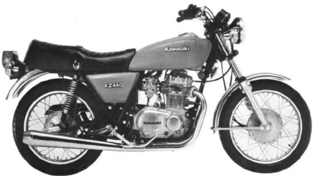
KZ440-C1 Left Side View
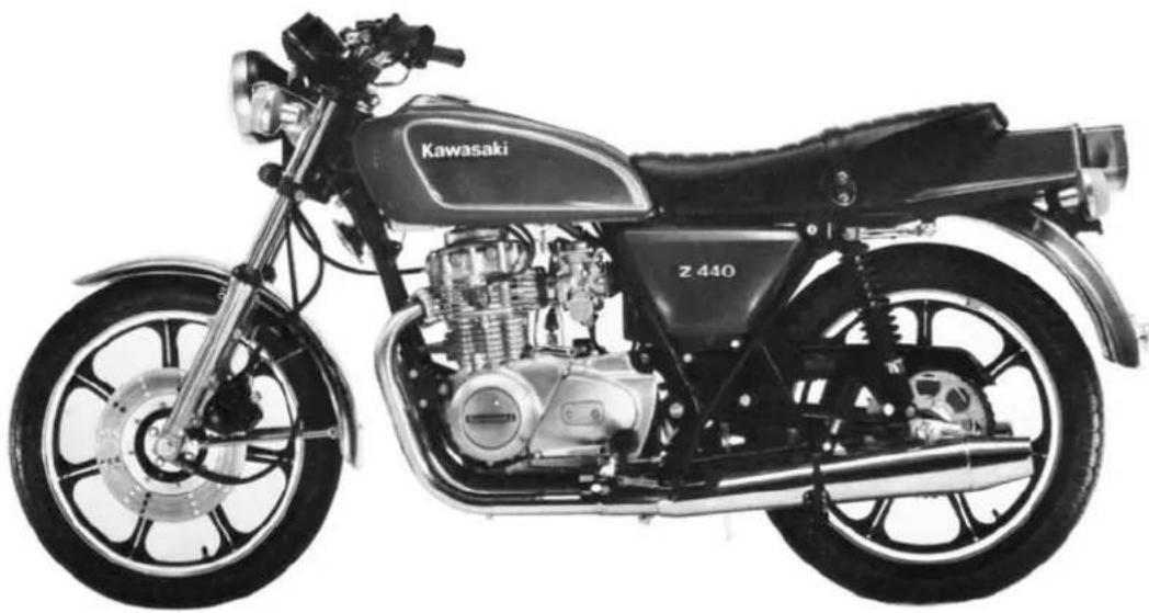
KZ440-C1 Right Side View

KZ440-D1 Left Side View

KZ440-D1 Right Side View

Specifications
Table of Contents
SPECIFICATIONS 10
ENGINE PERFORMANCE CURVES 14
RUNNING PERFORMANCE CURVES 15
PERIODIC MAINTENANCE CHART 16

10 SPECIFICATIONS
SPECIFICATIONS
| KZ440-A1 | KZ440-D1 | ||
| Dimensions | |||
| Overall length | 2,080 mm, E 2,120 mm | 2,080 mm | |
| Overall width | 810 mm | * | |
| Overall height | 1,180 mm | * | |
| Wheelbase | 1,390 mm | * | |
| Road clearance | 140 mm | * | |
| Dry weight | 169 kg, E 170 kg, G 171 kg | 169 kg | |
| Fuel tank capacity | 12 ℓ | * | |
| Performance | |||
| Climbing ability | 30° | 24° | |
| Braking distance | 13.5 m from 50 kph | * | |
| Minimum turning radius | 2.4 m | * | |
| Engine | |||
| Type | SOHC, 2 cylinder, 4-stroke, air-cooled | * | |
| Bore and stroke | 67.5 x 62.0 mm | * | |
| Displacement | 443 cc | * | |
| Compression ratio | 9.2 | * | |
| Maximum horsepower | 40 HP @8,500 rpm, G 27 HP @7,000 rpm | 40 HP @8,500 rpm | |
| Maximum torque | 3.6 kg-m @7,000 rpm, G 3.3 kg-m @3,000 rpm | 3.6 kg-m @7,000 rpm | |
| Valve timing | |||
| Inlet | Open | 27° BTDC | * |
| Close | 73° ABDC | * | |
| Duration | 280° | * | |
| Exhaust | Open | 70° BBDC | * |
| Close | 30° ATDC | * | |
| Duration | 280° | * | |
| Carburetors | Keihin CV36 x 2, G Keihin CV32 x 2 | Keihin CV36 x 2 | |
| Lubrication system | Forced lubrication (wet sump) | * | |
| Engine oil | SE class SAE 10W40, 10W50, 20W40, or 20W50 | * | |
| Engine oil capacity | 2.9 ℓ | * | |
| Starting system | Electric starter | * | |
| Ignition system | Battery and coil | * | |
| Ignition timing | From 10° BTDC @1,200 rpm to 35° BTDC @3,200 rpm | * | |
| Spark plugs | NGK B7ES or ND W22ES-U | * | |
| Transmission | |||
| Type | 6-speed, constant mesh, return shift | * | |
| Clutch | Wet, multi disc | * | |
| Gear ratio: 1st | 2.54 (33/13) | * | |
| 2nd | 1.75 (28/16) | ||
| 3rd | 1.32 (25/19) | ||
| 4th | 1.10 (23/21) | ||
| 5th | 0.96 (22/23) | ||
| 6th | 0.88 (21/24) | ||
| Primary reduction ratio | 2.43 (56/23) | * | |
| Final reduction ratio | 3.00 (45/15) | 2.73 (60/22) | |
| Overall drive ratio | 6.39 (Top gear) | 5.81 (Top gear) | |
Electrical Equipment
| Alternator Rated Output | 15 amp. @10,000 rpm, 14V | * |
| Regulator/Rectifier | Shindengen SH222-12B | * |
| Ignition coil | Nippon Denso 029700-3881 | * |
| Battery | Furukawa FB12A-A (12V 12AH) | * |
| Starter | Mitsuba SM-8203 | * |
| Headlight type | Sealed beam, E Semi-sealed | Sealed beam |
| Headlight | 12V 50/35W, E 12V 35/35W, F 12V 36/36W | 12V 50/35W |
| Tail/Brake light | 12V 8/27W, E 12V 5/21W | 12V 8/27W |
| Speedometer light | 12V 3.4W | * |
| Tachometer light | 12V 3.4W | * |
| Neutral indicator light | 12V 3.4W | * |
| High beam indicator light | 12V 3.4W | * |
| Turn signal/Running position lights | — | — |
| Turn signal lights | 12V 23W, E 12V 21W | 12V 23W |
| Turn signal indicator light | 12V 3.4W | * |
| Oil pressure indicator light | 12V 3.4W | * |
| Brake light failure indicator light | 12V 3.4W | * |
| Horn | 12V 2.5A | * |
| City light | E 12V 3.4W | — |
Frame
| Type | Tubular, double cradle | * | |
| Steering angle | 40° to either side | * | |
| Castor | 27.5° | * | |
| Trail | 112 mm | * | |
| Tire size | Front | 3.25S-19 4PR | * |
| Rear | 130/90-16 67S | * | |
| Suspension | Front | Telescopic fork | * |
| Rear | Swing arm | * | |
| Wheel travel | Front | 150 mm | * |
| Rear | 115 mm | * | |
| Front fork oil capacity (each fork) | 150 cc | * | |
| Front fork oil type | SAE 5W20 | * | |
Brakes
| Type | Front | Disc brake | * |
| Rear | Internal expansion, leading-trailing | * | |
| Effective disc diameter | Front | 230 mm | * |
| Brake drum inside diameterand width | Rear | 160 x 30 mm | * |
12 SPECIFICATIONS
SPECIFICATIONS
| KZ440-B1 | KZ440-C1 | ||
| Dimensions | |||
| Overall length | 2,045 mm | 2,045 mm, E2,070 mm | |
| Overall width | 810 mm | 810 mm, E775 mm | |
| Overall height | 1,130 mm | 1,130 mm, E1,070 mm | |
| Wheelbase | 1,365 mm | * | |
| Road clearance | 160 mm | 135 mm | |
| Dry weight | 159 kg | 166 kg | |
| Fuel tank capacity | 14 l | * | |
| Performance | |||
| Climbing ability | 30° | * | |
| Braking distance | 13.5 m from 50 kph | * | |
| Minimum turning radius | 2.3 m | * | |
| Engine | |||
| Type | SOHC, 2 cylinder, 4-stroke, air-cooled | * | |
| Bore and stroke | 67.5 x 62.0 mm | * | |
| Displacement | 443 cc | * | |
| Compression ratio | 9.2 | * | |
| Maximum horsepower | 40 HP @8,500 rpm | 41 HP @8,500 rpm, G26.7 HP @7,000 rpm | |
| Maximum torque | 3.6 kg-m @7,000 rpm | 3.6 kg-m @7,000 rpm, G3.3 kg-m @3,000 rpm | |
| Valve timing | |||
| Inlet | Open | 27° BTDC | * |
| Close | 73° ABDC | * | |
| Duration | 280° | * | |
| Exhaust | Open | 70° BBDC | * |
| Close | 30° ATDC | * | |
| Duration | 280° | * | |
| Carburetors | Keihin CV36 x 2 | Keihin CV36 x 2, G Keihin CV32 x 2 | |
| Lubrication system | Forced lubrication (wet sump) | * | |
| Engine oil | SE class SAE 10W40, 10W50, 20W40, or 20W50 | * | |
| Engine oil capacity | 2.9 l | * | |
| Starting system | Electric starter | * | |
| Ignition system | Battery and coil | * | |
| Ignition timing | From 10° BTDC @1,200 rpm to 35° BTDC @3,200 rpm | * | |
| Spark plugs | NGK B7ES or ND W22ES-U | * | |
| Transmission | |||
| Type | 6-speed, constant mesh, return shift | * | |
| Clutch | Wet, multi disc | * | |
| Gear ratio: | 1st | 2.54 (33/13) | * |
| 2nd | 1.75 (28/16) | * | |
| 3rd | 1.32 (25/19) | * | |
| 4th | 1.10 (23/21) | * | |
| 5th | 0.96 (22/23) | * | |
| 6th | 0.88 (21/24) | * | |
| Primary reduction ratio | 2.43 (56/23) | * | |
| Final reduction ratio | 3.00 (45/15) | * | |
| Overall drive ratio | 6.39 (Top gear) | * | |
| Electrical Equipment | |||
| Alternator Rated Output | 15 amp. @10,000 rpm, 14V | * | |
| Regulator/Rectifier | Shindengen SH222-12B | * | |
| Ignition coil | Nippon Denso 029700-3881 | * | |
| Battery | Furukawa FB12A-A (12V 12AH) | * | |
| Starter | Mitsuba SM-8203 | * | |
| Headlight type | Sealed beam | Semi-sealed | |
| Headlight | 12V 50/35W | 12V 50/40W, E12V 35/35W | |
| Tail/Brake light | 12V 8/27W | 12V 8/27W, E12V 5/21W | |
| Speedometer light | 12V 3.4W | * | |
| Tachometer light | 12V 3.4W | * | |
| Neutral indicator light | 12V 3.4W | * | |
| High beam indicator light | 12V 3.4W | * | |
| Turn signal/Running position lights | 12V 23/8W | — | |
| Turn signal lights | — | 12V 23W, E12V 21W | |
| Turn signal indicator light | 12V 3.4W | * | |
| Oil pressure indicator light | 12V 3.4W | * | |
| Brake light failure indicator light | 12V 3.4W | * | |
| Horn | 12V 2.5A | * | |
| City light | — | 12V 3.4W, E12V 4W | |
| Frame | |||
| Type | Tubular, double cradle | * | |
| Steering angle | 41° to either side | * | |
| Castor | 27° | * | |
| Trail | 100 mm | * | |
| Tire size | Front | 3.00S-18 4PR | * |
| Rear | 3.50S-18 4PR | * | |
| Suspension | Front | Telescopic fork | * |
| Rear | Swing arm | * | |
| Wheel travel | Front | 150 mm | * |
| Rear | 95 mm | * | |
| Front fork oil capacity (each fork) | 150 cc | * | |
| Front fork oil type | SAE 5W20 | * | |
| Brakes | |||
| Type | Front | Internal expansion, two-leading | Disc brake |
| Rear | Internal expansion, leading-trailing | * | |
| Effective disc diameter | — | 230 mm | |
| Brake drum inside diameter | |||
| and width | Front | 180 x 30 mm | — |
| Rear | 160 x 30 mm | * | |
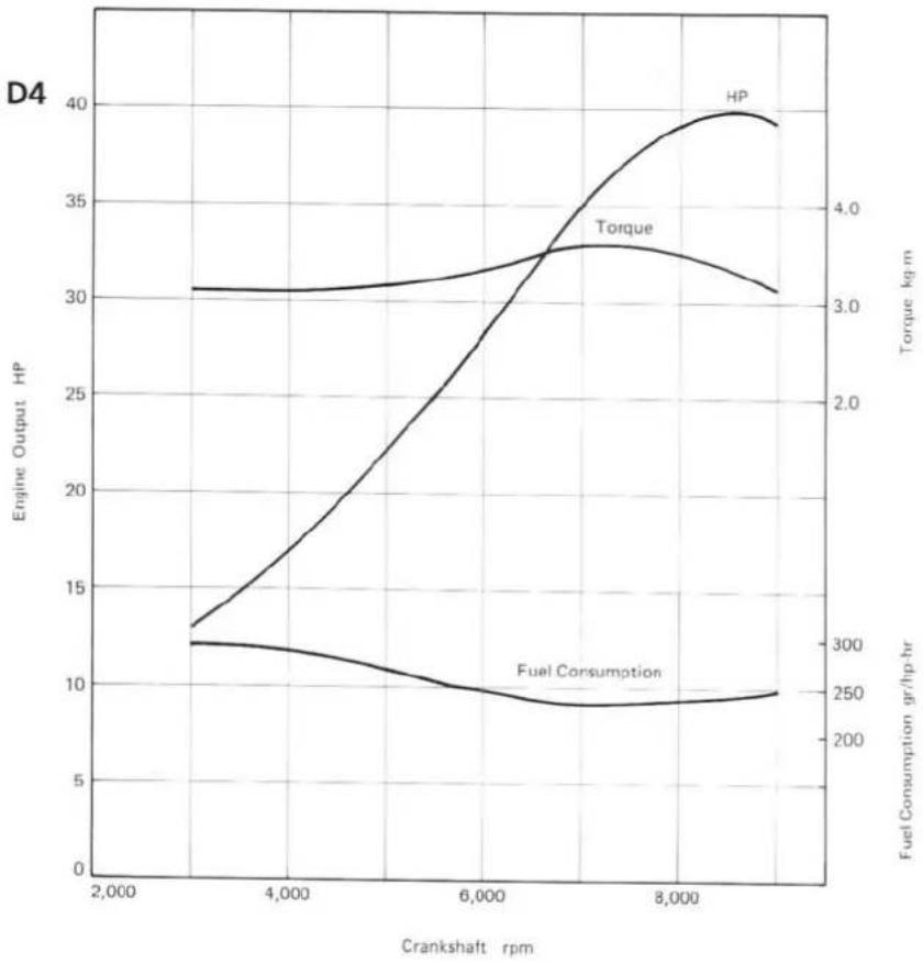
ENGINE PERFORMANCE CURVES
KZ440-A1, A2, A3
KZ440-B1, B2
KZ440-D1, D2, D3, D4
KZ440-C1, C2

KZ440-A1, A2, A3, B1, B2

KZ440-C1, C2
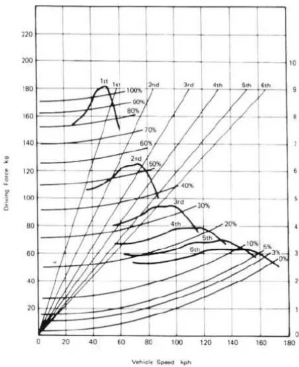
KZ440-D1, D2, D3, D4

PERIODIC MAINTENANCE CHART (KZ440-A1, B1, C1, D1)
The maintenance and adjustments must be done in accordance with this chart to keep the motorcycle in good running condition. The initial maintenance is vitally important and must not be neglected.
| FREQUENCY OPERATION | Whichever comes first | ODOMETER READING* | |||||||
| Every | 800 km | 5,000 km | 10,000 km | 15,000 km | 20,000 km | 25,000 km | 30,000 km | See Page | |
| Battery electrolyte level - check † | month | ● | ● | ● | ● | ● | ● | ● | 214 |
| Brake adjustment - check † | ● | ● | ● | ● | ● | ● | ● | 32 | |
| Brake wear - check † | ● | ● | ● | ● | ● | ● | 201,202 | ||
| Brake fluid level - check † (If applicable) | month | ● | ● | ● | ● | ● | ● | ● | 198 |
| Brake fluid - change (If applicable) | year | ● | ● | ● | 198 | ||||
| Clutch - adjust | ● | ● | ● | ● | ● | ● | ● | 25 | |
| Carburetors - adjust | ● | ● | ● | ● | ● | ● | ● | 22 | |
| Throttle cable(s) - adjust | ● | ● | ● | ● | ● | ● | ● | 21 | |
| Steering play - check † | ● | ● | ● | ● | ● | ● | ● | 35 | |
| Spoke tightness and rim runout - check † (If applicable) | ● | ● | ● | ● | ● | ● | ● | 192 | |
| Drive chain wear - check † (If applicable) | ● | ● | ● | ● | ● | ● | 195 | ||
| Front fork - inspect/clean | ● | ● | ● | ● | ● | ● | 207 | ||
| Rear shock absorbers - inspect | ● | ● | ● | ● | ● | ● | ● | 208 | |
| Nuts, Bolts, Fasteners - check and torque | ● | ● | ● | ● | 43~46 | ||||
| Spark plugs - clean and gap † | ● | ● | ● | ● | ● | ● | ● | 18 | |
| Points, timing - check † | ● | ● | ● | ● | ● | ● | ● | 18 | |
| Valve clearance - check † | ● | ● | ● | ● | ● | ● | ● | 20,159 | |
| Air cleaner element - clean | ● | ● | ● | 146 | |||||
| Air cleaner element - replace | 5 cleanings | ● | ● | ● | 147 | ||||
| Fuel system - clean | ● | ● | ● | ● | ● | ● | ● | 27 | |
| Tire tread wear - check † | ● | ● | ● | ● | ● | ● | 191 | ||
| Engine oil - change | year | ● | ● | ● | ● | ● | ● | ● | 26 |
| Oil filter - replace | ● | ● | ● | ● | 27,185 | ||||
| General lubrication - perform | ● | ● | ● | ● | ● | ● | 38~40 | ||
| Front fork oil - change | ● | ● | ● | 207 | |||||
| Timing advancer - lubricate | ● | ● | ● | 223 | |||||
| Swing arm - lubricate | ● | ● | ● | 210 | |||||
| Wheel bearings - grease | 2 years | ● | 193 | ||||||
| Speedometer gear housing - grease | 2 years | ● | 194 | ||||||
| Brake camshaft - grease | 2 years | ● | 203 | ||||||
| Steering stem bearings - grease | 2 years | ● | 204 | ||||||
| Drive belt tension - check † (If applicable) | ● | ● | ● | ● | ● | ● | ● | 31 | |
| Drive belt - check † (If applicable) | ● | ● | ● | ● | ● | ● | ● | 31,197 | |
| Drive chain - lubricate (If applicable) | Every 300 km | 195 | |||||||
| Drive chain - adjust | Every 800 km | 30 | |||||||
* For higher odometer readings, repeat at the frequency interval established here.
†Replace, add or adjust if necessary.
Adjustment—Engine
Table of Contents

SPARK PLUGS....18
IGNITION TIMING 18
VALVE CLEARANCE 20
THROTTLE CABLE 21
CARBURETORS 22
CLUTCH....25
ENGINE OIL 26
FUEL SYSTEM 27
18 ADJUSTMENT-ENGINE
SPARK PLUGS
Neglecting the spark plugs eventually leads to difficult starting and poor performance. During normal operation, the electrodes gradually burn away and carbon builds up along the insulator. In accordance with the Periodic Maintenance Chart (Pg. 16), the plugs should be removed for inspection, cleaning, and to reset the gaps.
- Remove the spark plugs using a spark plug wrench.
- Clean the spark plugs, preferably in a sand-blasting device, and then clean off any abrasive particles. The plug may also be cleaned using a high flash-point solvent and a wire brush or other suitable tool. If the spark plug electrodes are corroded or damaged, or if the insulator is cracked, replace the plug. Use the standard plug or its equivalent.
●Measure the gap with a wire-type thickness gauge. If the gap is incorrect, carefully bend the side electrode with a suitable tool, to obtain the correct gap.
Spark Plug Gap
B1

Table B1 Spark Plug
| Plug | NGK B7ES, NDW22ES-U |
| Gap | 0.7~0.8 mm |
| Tightening Torque | 2.8 kg-m (20 ft-lbs) |
●Tighten the spark plugs in the cylinder head to the specified torque.
NOTE: Refer to electrical maintenance section, Pg. 223, for detailed spark plug information.
IGNITION TIMING
*Incorrect ignition timing can cause poor performance, knocking, overheating, and serious engine damage. Periodic adjustment will be necessary to compensate for wear of parts, and the ignition timing must be checked whenever ignition related parts have been disassembled or replaced.
Correct ignition timing is achieved by first obtaining the correct contact breaker point gap (this can also be achieved by adjusting the dwell angle to the specified amount) and then changing the position of the contact breaker mounting plate. Often the first step returns the timing very close to the correct original setting. Once the timing has been adjusted, it may be checked for accuracy by the use of a strobe light.
NOTE: The dwell angle is the angular range for which the contact breaker points are closed. This allows the current to flow in the ignition coil primary winding.
Point Gap/Dwell Angle Adjustment
To check the point gap:
- Remove the screws (2), and remove the contact breaker cover.
- Clean the points with clean paper or cloth using an oil-free solvent. A business card soaked in trichloroethylene can be used to remove traces of oil. To repair light damage, use emery cloth or an oilstone. If the points are badly worn down or damaged, or if the spring is weak, replace the contact breaker.
- Lubricate the point cam felt sparingly with suitable point cam lubricant. Do not overlubricate. Replace the felt if it is worn.
- Check to see that the ignition switch is turned off.
- Using a 17 mm wrench on the crankshaft, turn the engine counterclockwise until the contact breaker points are at their widest opening.
- Determine the size of the point gap with a thickness gauge, or measure the dwell angle using a dwell angle tester.
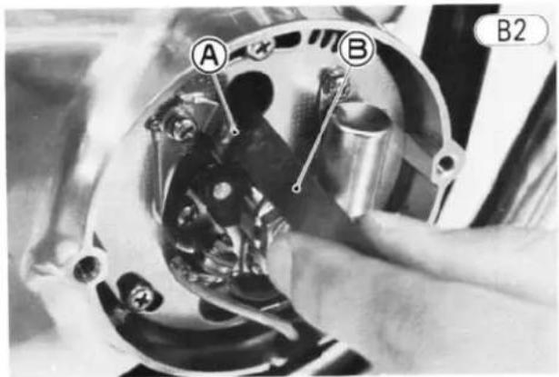
A. Contact Breaker Points
B. Thickness Gauge
Table B2 Contact Breaker
| Standard | |
| Point Gap | 0.3~0.4 mm |
| Dwell Angle | 185~200°(51~56%) |
NOTE: The point gap is set more precisely using a dwell angle tester instead of a thickness gauge. Connect a dwell angle tester in the manner prescribed by the manufacturer in order to check the dwell angle.
WARNING When measuring the dwell angle, make sure that no tools, clothes, or meter leads touch the spinning crankshaft. Touching the crankshaft of a running engine could cause an injury.
To adjust the point gap:
- If the gap or dwell angle is not the same as the specification, loosen the contact breaker base screws (2) just enough so that a slot screwdriver can be used at the
contact breaker pry point to change the gap or dwell angle. Adjust the contact breaker until the correct point gap or dwell angle specification is obtained.

A. Base Screws
B. Pry Point
●Tighten the screws (2).
●Perform the timing test.
Timing Test
To inspect the ignition timing there are two marks on the automatic timing advancer. One ("F" mark) is for checking the timing before advancing, and the other (a pair of lines) for checking the timing after it has advanced.
Timing Advancer
B4
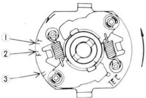
- "T" Mark
- "F" Mark
- Advanced Mark
To check and adjust the timing (static):
- Check the point gap, and adjust if necessary.
- With the ignition switch turned off, turn the engine stop switch to one of the "OFF" positions to make the ohmmeter flicker easier to read.
- Set an ohmmeter to the x 1 Ω range and connect it across the points, one lead to the wire coming from the points (or to the spring leaf), and the other ohmmeter lead to chassis ground (engine, frame, contact breaker mounting etc.). Make sure that both leads are securely connected.
- Turning the cranksahft counterclockwise, check to see if the "F" mark is aligned with the timing mark when the needle jumps.
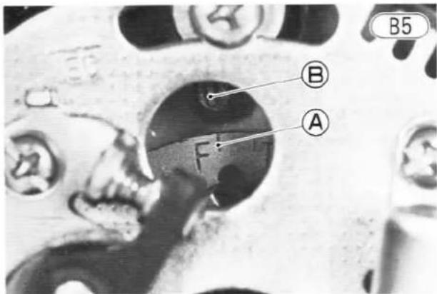
A. "F" Mark
B. Timing Mark
- If the timing is incorrect, turn and stop the crankshaft so that the "F" mark (the line adjoining the "F") on the timing advancer is aligned with the timing mark.
- Loosen the contact breaker mounting plate screws (3), and turn the mounting plate (using a screwdriver in the pry points) so that the contacts are just at the point of opening. This point can be found by watching the ohmmeter needle, which will flicker just when the points begin to open or close.

A. Mounting Plate Screws
C. Pry Points
B. Mounting Plate
●Tighten the mounting plate screws (3).
- Check the point gap again, and adjust if it was disturbed.
- Disconnect the ohmmeter leads.
●Install the contact breaker cover and its gasket.
To check the timing (dynamic):
- Check the point gap, and adjust if necessary.
- Connect a strobe light in the manner prescribed by the manufacturer in order to check the ignition timing under operating conditions.
- Start the engine, and direct the light at the timing mark through the inspection window. At low engine speed the timing mark and the "F" mark on the timing advancer must be aligned for correct low rpm ignition timing (Fig. B5). At high engine speed (above
20 ADJUSTMENT—ENGINE
3,400 rpm) the timing mark and the pair of lines on the timing advancer must be aligned for correct high rpm ignition timing as shown in Fig. B7. If both low and high rpm ignition timing are incorrect, adjust the timing as just explained. If either low or high rpm ignition timing is correct but the other is not, examine the timing advancer mechanism (Pg. 223).

A. Advanced Mark
B. Timing Mark
Table B3 Timing Advancing
| Engine Speed | |
| Advance Begins | 1,400~1,600 rpm |
| Full Advance | 3,000~3,400 rpm |
- Check the point gap again, and adjust if it was disturbed.
●Install the contact breaker cover and its gasket.
VALVE CLEARANCE
Valve and valve seat wear decreases valve clearance, upsetting valve timing. If valve clearance is left unadjusted, the wear will eventually cause the valves to remain partly open; which lowers performance, burns the valves and valve seats, and may cause serious engine damage.
. Valve clearance for each valve should be checked and adjusted if incorrect, in accordance with the Periodic Maintenance Chart (Pg. 16) and any time clearance may have been affected by disassembly.
When carrying out adjustment, be careful to adjust within the specified clearance. Adjusting to a larger value will both disturb valve timing and cause engine noise.
NOTE: Valve clearance must be checked when the engine is cold.
To check and adjust the valve clearance:
- Remove the fuel tank (Pg. 50).
- Remove the valve adjusting caps.

A. Valve Adjusting Caps
- Remove the screws (2), and remove the contact breaker cover.
- Using a 17 mm wrench, turn the crankshaft counterclockwise while watching the movement of the inlet valve (the valve to the rear) on the right side. When the valve has just finished opening and closing (moving downward and returning upward), turn the crankshaft in the same direction (counterclockwise) for about another 1/4 turn until the "T" mark (the line adjoining the "T") on the timing advancer aligns with the timing mark.

A. "T" Mark
B. Timing Mark
- At this crankshaft position, the piston in the right cylinder is at the end of its compression stroke such that the inlet and exhaust valve for the right cylinder can be checked.
●Measure the clearance of each valve by inserting a thickness gauge (special tool) between the adjusting screw and the valve stem.
Table B4 Valve Adjustment (when cold)
| Valve Clearance (for both inlet and exhaust) | 0.17~0.22 mm |
| Locknut Tightening Torque | 1.5 kg-m (11.0 ft-lbs) |
- If a valve clearance is incorrect, loosen its adjusting screw locknut, and turn the adjusting screw until correct clearance is obtained.

A. Adjusting Screw
C. Locknut
B. Thickness Gauge (57001-1013)
●Tighten the locknut to the specified torque.
●After finishing with the right cylinder valves, turn the crankshaft counterclockwise one full turn so that the "T" mark again aligns with the timing mark. Check the left cylinder valves, and adjust if necessary.
●Install the valve adjusting caps together with O rings.
●Install the contact breaker cover and its gasket.
●Install the fuel tank (Pg 50).
THROTTLE CABLE (one throttle cable model)
There is a throttle cable to open the butterfly valves in the carburetors. If the cable is too loose due either to cable stretch or maladjustment, the excessive play in the throttle grip will cause a delay in throttle response, which will be especially noticeable at low rpm. Also, the butterfly valves may not open fully at full throttle. On the other hand, if the cable is too tight, the throttle will be hard to control, and the idle speed will be erratic.
To check the throttle cable adjustment:
- Check that there is 2\~3 mm throttle grip play when lightly turning the throttle grip back and forth.
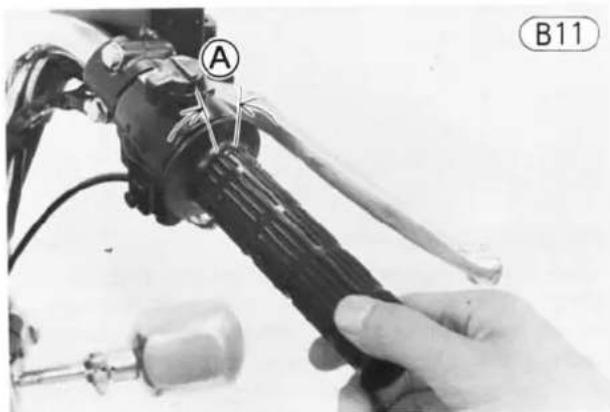
A. 2\~3 mm
To adjust the throttle cable:
If the cable has improper play, adjust it as follows:
- Loosen the locknut at the throttle grip, and turn the adjusting nut until the proper amount of throttle grip play is obtained. Tighten the locknut.
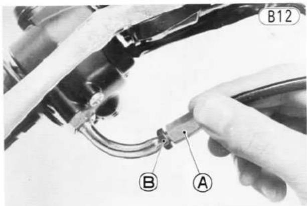
A. Adjusting Nut
B. Locknut
NOTE: If the throttle cable cannot be adjusted by using the cable adjusting nut at the upper end of the throttle cable, use the cable adjuster at the lower end of the throttle cable (at the carburetor). Do not forget to securely tighten the adjuster locknut.
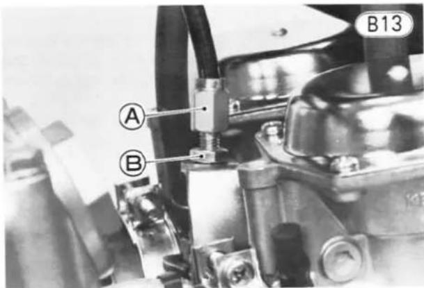
A. Adjuster
B. Locknut
THROTTLE CABLES
(two throttle cables model)
There are two throttle cables: an accelerator cable for opening the butterfly valves, and a decelerator cable for closing them. If the cables are too loose due either to cable stretch or maladjustment, the excessive play in the throttle grip will cause a delay in throttle response, which will be especially noticeable at low rpm. Also, the butterfly valves may not open fully at full throttle. On
22 ADJUSTMENT—ENGINE
the other hand, if the cables are too tight, the throttle will be hard to control, and the idle speed will be erratic.
To check the throttle cable adjustment:
- Check that there is 2\~3 mm throttle grip play (Fig. B14).

A. 2\~3 mm
- Push the throttle grip completely closed. At this time the decelerator throttle cable bracket should be pushed down 1\~2 mm. When the throttle grip is released, the cable bracket should be returned to its rest position by the spring tension.
NOTE: This assures that the stress of throttle grip return will be taken by the throttle grip, protecting the carburetor linkage mechanism.
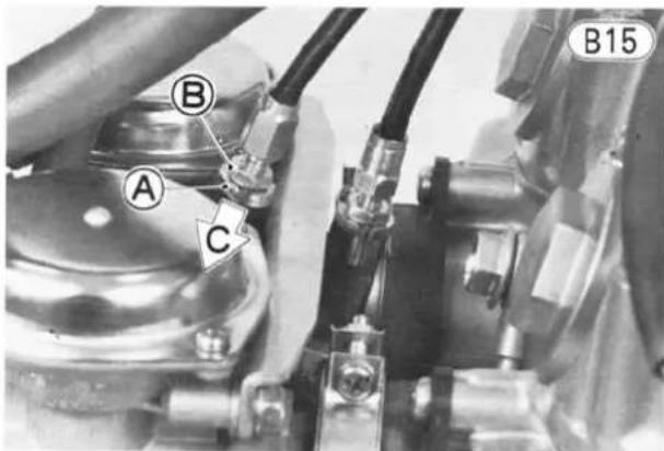
A. Decelerator Throttle Cable Bracket
B. Locknut C. 1\~2 mm
To adjust the throttle cables:
If any one of the above checks shows improper adjustment, adjust the throttle cables as follows:
- Loosen the locknuts, and screw both throttle cable adjusting nuts in fully at the upper end of the throttle cables so as to give the throttle grip plenty of play.
- Turn out the decelerator cable adjusting nut until the cable bracket is pushed down 1 \~ 2 mm when the throttle grip is completely closed. Tighten the locknut.

A. Decelerator Cable Adjusting Nut
B. Locknut
- Turn the accelerator cable adjusting nut until 2\~3 mm of throttle grip play is obtained. Tighten the locknut.

A. Accelerator Cable Adjusting Nut
B. Locknut
NOTE: If the throttle cables cannot be adjusted by using the cable adjusting nuts at the upper end of the throttle cables, use the cable adjusters at the lower ends of the throttle cables. Do not forget to securely tighten the adjuster locknuts.
CARBURETORS
For internal carburetor maintenance and replacement of parts, see the maintenance section of this manual. The following procedure covers the idling adjustment, which is the adjustment necessary in periodic maintenance and whenever the idle setting has been disturbed. This procedure also includes the necessary steps for obtaining proper carburetor synchronization.
When the idle speed is too low, the engine may stall; when the idle speed is too high, the fuel consumption becomes excessive, and the resulting lack of engine braking may make the motorcycle difficult to control. Poor carburetor synchronization will cause unstable idling, sluggish throttle response, and reduced engine power and performance.
The following procedure consists of two parts: idling adjustment and carburetor synchronization.
Idling Adjustment
1) Idle speed adjustment
- Start the engine, and warm it up thoroughly.
- Adjust the idle speed to 1,100\~1,300 rpm by turning the idle adjusting screw.

A. Idle Adjusting Screw

A. Idle Adjusting Screw (West German Model)
- Open and close the throttle a few times to make sure that the idle speed does not change. Readjust if necessary.
NOTE: With the engine idle, turn the handlebar to either side. If handlebar movement changes idle speed, the throttle cable may be improperly adjusted or incorrectly routed, or it may be damaged.
WARNING
Operation with improperly adjusted, incorrectly routed, or damaged cable could
result in an unsafe riding condition.
2) Idle mixture adjustment (not for US model)
- For all carburetor, turn in the pilot screw of each carburetor until it seats lightly, and then back it out 2 3/4 (West German Model: 2 1/4 ) turns.

A. Pilot Screw

A. Pilot Screw (West German Model)
- Adjust the idle speed.
NOTE: If proper idle speed cannot be obtained by this adjustment alone, first check the following and correct as necessary.
Engine Oil (Pg. 26)
Spark Plugs (Pg. 18)
Ignition Timing (Pg. 18)
Throttle Cable (Pg. 21)
Cylinder Compression (Pg. 164)
Air Cleaner Element (Pg. 146)
Air Cleaner Duct and Carburetor Holder Leakage
Valve Clearance (Pg. 20)
Carburetor Synchronization
Fine adjustment of carburetor synchronization, necessary for smooth engine operation, requires the use of vacuum gauges. Differences between the left and right cylinders might be found from exhaust noise and exhaust pressure; but to accurately synchronize each carburetor, the use of vacuum gauges is essential.
24 ADJUSTMENT-ENGINE
To check carburetor synchronization:
- Start the engine, and warm it up thoroughly.
●Perform idling adjustment (Pg. 23).
-Stop the engine.
• Install the vacuum gauge as follows.
For the models except West German model:
○Remove the rubber cap from the left carburetor.
- Slide the hose clamp out of place, and pull the vacuum hose off the right carburetor.
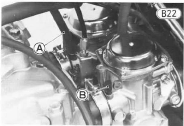
A. Vacuum Hose
B. Rubber Cap
- Fit the hose from vacuum gauge onto the fitting on each carburetor.
For the West German model:
○Remove the vacuum plugs from each carburetor, and attach the vacuum gauge and adapter (special tools).
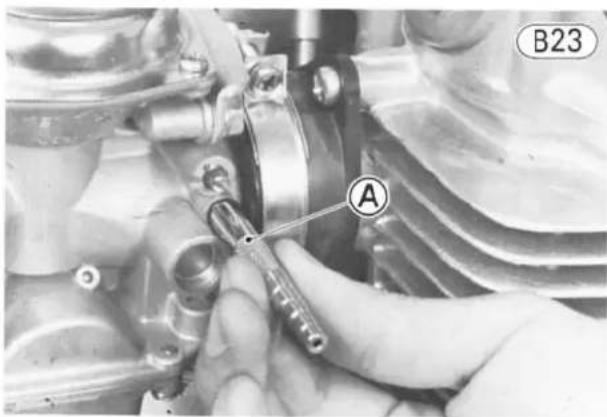
A. Vacuum Gauge Adapter (57001-401)
- Turn the fuel tap lever to the "PRI" position, and start the engine.
- With the engine running at idle speed, slowly turn the vacuum gauge damper valves until gauge needle flutter is less than 3 cmHg and note the gauge readings.
Table B5 Engine Vacuum
| Difference between two cylinders | less than 3 cmHg |

A. Damper Valve
B. Vacuum Gauge (57001-226)
- If there is a difference of more than the specified value between the two gauges, stop the engine, and synchronize the carburetors according to the following procedure.
To synchronize carburetors:
- Remove the fuel tank (Pg. 50), and supply fuel for the carburetors by some means during adjustment.
WARNING Use extreme caution when working with gasoline, open fuel lines, etc. to avoid a fire or explosion.
- With the engine running at idle speed, loosen the locknut and alter the balance adjusting screw position using the balance adjuster (special tool) or suitable tools to obtain a difference in readings which is less than the specified value. Tighten the locknut without changing the position of the adjusting screw.
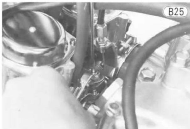

A. Balance Adjusting Screw
B. Locknut

A. Balance Adjuster (57001-351)

A. Balance Adjusting Screw
B. Locknut
●Perform idle adjustment again.
- Open the throttle grip and let it snap shut a few times. Make sure the vacuum readings stay within the specified vacuum reading. If they do not, repeat the last two steps.
- If any gauge reads a value less than 15 cmHg after synchronizing the carburetors; check the points listed in the end of the idling adjustment.
- Detach the vacuum gauge, and install the rubber cap and vacuum hose on the carburetors. Slide the hose clamp back into place.
●Install the fuel tank (Pg. 50).
CLUTCH
Clutch cable stretch causes the clutch lever to develop excessive play. Too much play will prevent complete disengagement and may result in shifting difficulty and possible clutch and transmission damage. Most of the play must be adjusted out, but a small amount must remain so that the clutch release lever will function properly.
Clutch plate wear also causes the clutch to go out of adjustment. This wear causes the play between the push rod and the clutch release to gradually diminish until the push rod touches the clutch release. When this play is lost, the clutch will not engage fully, causing the clutch to slip.
NOTE: Even though the proper amount of play exists at the clutch lever, clutch lever play alone cannot be used to determine whenever or not the clutch requires adjustment.
The following adjustment procedure compensates for both cable stretch and plate wear.
WARNING To avoid a serious burn, never touch the hot engine or an exhaust pipe during clutch adjustment.
To adjust the clutch:
- Loosen the locknut, and turn in fully the adjuster at the center of the clutch cable to give the cable plenty of play (Fig. B29).
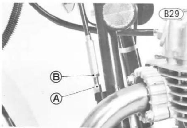
A. Adjuster
B. Locknut
- Loosen the knurled locknut at the clutch lever just enough so that the adjuster will turn freely, and then turn the adjuster to make a 5\~6 mm gap between the adjuster and knurled locknut.
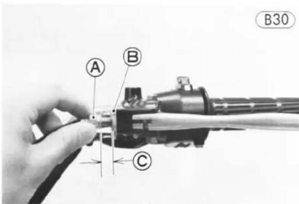
A. Adjuster
C. 5\~6 mm
B. Knurled Locknut
- Remove the clutch release adjusting cover.
-
Loosen the locknut, and turn in the adjusting screw until the screw turns without drag.
-
Turn out the adjusting screw until it becomes hard to turn. This is the point where the clutch is just starting the release.
- Turn in the adjusting screw 1/4 turn from that point, and tighten the locknut.

A. Locknut
B. Adjusting Screw
C. 1/4 Turn
●Take up all the cable play with the adjuster at the center of the cable, and then tighten the locknut.
WARNING Be sure the cable is fully seated in the engine sprocket cover hole, or it could slip into place later, creating enough cable play to prevent clutch disengagement.

A. Clutch Cable
- Turn the adjuster at the clutch lever so that the clutch lever will have 2\~3 mm of play and tighten the knurled locknut.
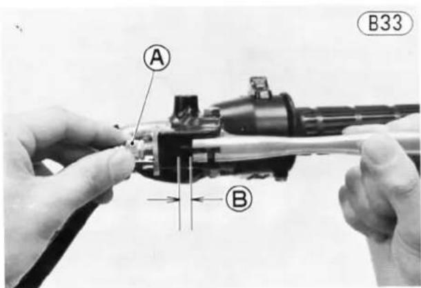
A. Adjuster
B. 2\~3 mm
●Install the clutch release adjusting cover.
ENGINE OIL
In order for the engine, transmission, and clutch to function properly; maintain the engine oil at the proper level, and change the oil in accordance with the Periodic Maintenance Chart (Pg. 16). Motorcycle operation with insufficient, deteriorated, or contaminated engine oil will cause accelerated wear and may result in engine or transmission seizure.
Oil Level Inspection
- Situate the motorcycle so that it is perpendicular to the ground.
- If the oil has just been changed, start the engine and run it for several minutes at idle speed. This fills the oil filter with oil. Stop the engine, then wait several minutes until the oil settles.
CAUTION
Run the engine at idle speed for several minutes. Racing the engine before the
oil reaches every part can cause engine seizure.
- If the motorcycle has just been used, wait several minutes for all the oil to drain down.
- Check the engine oil level through the oil level gauge in the lower right side of the engine. With the motorcycle held level or on the center stand, the oil level should come up between the lines next to the gauge.

A. Level Lines
B. Oil Level Gauge
- If the oil level is too high, remove the excess oil, using a syringe or some other suitable device.
- If the amount of oil is insufficient, add the correct amount of oil through the oil filler opening. Use the same type and make of oil that is already in the engine.
CAUTION
If the engine oil get extremely low or if the oil pump or oil passages clog up or
otherwise do not function properly, the red oil pressure warning light in the switch panel will light. If this light stays on when the engine speed is above 1,500 rpm, stop the engine immediately and find the cause.
WARNING
If the engine runs without oil, it will be severely damaged. In addition, the engine
may suddenly seize, locking the rear wheel and causing an accident if the clutch lever is not pulled in fast enough.
Oil and Oil Filter Change
●Warm up the engine thoroughly, and then stop the engine.
- Situate the motorcycle so that it is perpendicular to the ground, place an oil pan beneath the engine, and remove the engine drain plug.

A. Engine Drain Plug
B. Mounting Bolt
- If the oil filter is to be changed, replace the oil filter as explained on Pg. 84.
- After the oil has completely drained out, install the drain plug and gasket. Replace the damaged gasket with a new one. Proper torque for the engine drain plug is 3.0 kg·m (22 ft·lbs).
-
Fill the engine up to the upper level with SE class SAE 10W40, 10W50, 20W40, or 20W50 motor oil. It will take about 2.9 liters when the filter is changed. When the filter is not changed, a refill takes about 2.5 liters.
NOTE: After the engine has been run and then stopped for a few minutes, the oil level should be between the upper and lower marks. -
Never clean out the fuel system when the engine is still warm.
-
Wipe any fuel off the engine before starting it.
-
Run the ends of the overflow tubes into a suitable container, and turn the tap to the "PRI" position.
- Loosen the drain screws to drain the tank and carburetor float bowls through the overflow tubes until only fuel comes out, and tighten the drain screws. Turn the tap to the "ON" or "RES" position.
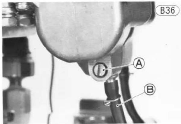
A. Drain Screw
B. Overflow Tube
- If any dirt comes out, clean the following parts in accordance with the procedures in the Maintenance Section.
○Fuel Tank (Pg. 147)
○Fuel Tap (Pg. 147)
○Carburetors (Pg. 148)
FUEL SYSTEM
Water anywhere in the fuel system can cause starting difficulty, poor running, and lack of power. Clean out the fuel system as follows:
WARNING
- Clean the fuel system in a well-ventilated area, and take ample care
that there are no sparks or flame anywhere near the working area.
Adjustment—Chassis
Table of Contents
REAR SHOCK ABSORBERS 30
DRIVE CHAIN (KZ440-A, B, C) 30
DRIVE BELT (KZ440-D) 31
BRAKES....32
Front Brake (KZ440A, C, D) 32
Front Brake (KZ440B) 32
Rear Brake 34
BRAKE LIGHT SWITCH 35
STEERING 35
WHEEL BALANCE 36
HEADLIGHT 37
AUTOMATIC SIDE STAND RETURN MECHANISM 38
LUBRICATION 38
30 ADJUSTMENT-CHASSIS
REAR SHOCK ABSORBERS
The rear shock absorbers can be adjusted to one of five positions to suit riding conditions. They can be left soft for average riding but should be adjusted harder for high speed riding, riding on bad roads, or riding with a passenger. Shock absorbers adjusted either too soft or too hard adversely affect riding comfort and stability.
To adjust the rear shock absorbers:
●Turn the adjusting sleeve on each shock absorber to the desired position with a hook spanner. The higher the adjusting sleeve is positioned, the stronger the spring tension, and the harder the ride.
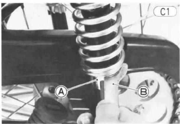
A. Adjusting Sleeve
B. Hook Spanner
- Check to see that both adjusting sleeves are turned to the same relative position.

If they are not adjusted to the same position, an unsafe riding condition may
result.
DRIVE CHAIN (KZ440-A, B, C)
Chain and sprocket wear causes the chain to stretch, which results in power loss, accelerated chain and sprocket wear, and increased noise. A chain that has been adjusted too loose may be thrown off the sprockets. A chain that has been adjusted too tight will wear excessively and possibly break.
To check the drive chain slack:
- Check to see if the drive chain wear is past the service limit (Pg. 195). A chain worn past the service limit must be replaced with a new one.
A chain worn past the service limit must be replaced. Such wear cannot be ad-ensated for by adjustment.
- Set the motorcycle up on its center stand or side stand.
- Rotate the rear wheel to find the position where the chain is tightest, and measure the vertical movement midway between the sprockets.

- If the drive chain is too tight or too loose, adjust it so that the vertical movement will be within the standard value.
Table C1 Drive Chain Slack
| Vertical Movement | ||
| Model | Standard(no adjustment required) | Too tight or too loose (adjust-ment required) |
| KZ440-A,C(on center stand) | 25~30 mm | less than 25 mm more than 35 mm |
| KZ440-B(on side stand) | 20~25 mm | less than 20 mm more than 30 mm |
To adjust the drive chain:
- Remove the safety clip, and loosen the nut at the rear end of the torque link.
CAUTION If you don't loosen the torque link nut, it may lead to brake panel fracture when the chain adjusters are set.

A. Torque Link Nut
B. Clip
- Loosen the left and right chain adjusting bolt locknuts.
- Remove the axle cotter pin and loosen the axle nut.

A. Adjusting Bolt
D. Axle Nut
B. Locknut
E. Notch
C. Cotter Pin
F. Alignment Marks
- If the chain is too tight, back out the left and right chain adjusting bolts evenly, and kick the wheel forward until the chain is too loose.
- Turn the left and right chain adjusting bolts evenly until the drive chain has the correct amount of slack. To keep the chain and wheel aligned, the notch on the left chain adjuster should align with the same swing arm mark that the right chain adjuster notch aligns with.
NOTE: Wheel alignment can also be checked using the straightedge or string method.
WARNING
Misalignment of the wheel will result in abnormal wear, and may result in an un-
unsafe riding condition.
- Tighten both chain adjuster locknuts (Make sure the axle stays aligned).
- Center the brake panel assembly in the brake drum. This is done by tightening the axle lightly, spinning the wheel, and depressing the brake pedal forcefully. The partially tightened axle allows the brake panel assembly to center itself within the brake drum.
NOTE: This procedure can prevent a soft, or "spongy feeling" brake.
●Tighten the axle nut to 7.5 kg-m (54 ft-lbs) of torque. - Rotate the wheel, measure the vertical movement again at the tightest position, and readjust if necessary.
- Insert a new cotter pin through the axle nut and axle, and spread its ends.
● Tighten the torque link rear nut to 3.3 kg-m (24 ft-lbs) of torque, and then insert the safety clip. - Check the brake (Pg. 34).
DRIVE BELT (KZ440-D)
It is very important to maintain the tension of the belt within the usable range (between the upper and lower lines) of the tension gauge (owner's tool) in order to run safely and prolong the life of the belt. A belt that has been adjusted too loosely may slip over the pulley teeth. A belt that has been maladjusted will result in shorter belt life.
To check the drive belt tension:
- Set the motorcycle up on its center stand.
●Visually inspect the belt for wear and external appearance. Refer to the Maintenance Section for more detailed information.
WARNING
A belt worn past the nylon fabric facing must be replaced. Such a worn belt may
cause a serious accident.
- Install the tension gauge at the position shown in Fig. C5. The rod of the tension gauge must face the swing arm, and the body must be placed on the top of the belt tooth.
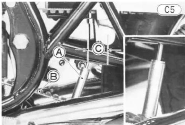
A. Tension Gauge
B. Drive Belt
C. 25 mm
C6
Construction of Tension Gauge

- Rod
A. Upper Line
- Body
B. Lower Line
- Spring
- Adjust the tension if the top of the body does not align with the upper line on the rod.
To adjust the drive belt tension:
●Make sure that the tension gauge is not left on the belt.
- Remove the safety clip, and loosen the nut at the rear end of the torque link (See Fig. C3).
32 ADJUSTMENT-CHASSIS
CAUTION
If you don't loosen the torque link nut, it may lead to brake panel fracture when re set.
●Loosen the left and right belt adjusting bolt locknuts.
- Remove the axle cotter pin, and loosen the axle nut (See Fig. C4).
- When the belt is too tight, back out both the belt adjusting bolts evenly, and push the wheel forward until the belt is too loose.
- When the belt is too loose, turn in both the belt adjusting bolts evenly. To keep the belt and wheel aligned, the notch on the left belt adjuster should align with the same swing arm mark that the right belt adjuster notch aligns with.
NOTE: Wheel alignment can also be checked using the straightedge or string method.
WARNING
Misalignment of the wheel will result in abnormal wear, and may result in an undition.
●Measure the belt tension at several positions, and adjust the tension so that the top of the body aligns with the upper line on the rod.
NOTE: Check the tension at first 800 km ride after belt replacement.
- Repeat the above three steps until the proper tension is obtained.
●Tighten both belt adjusting bolt locknuts, and make sure the axle stays aligned.
- Center the brake panel assembly in the brake drum. This is done by tightening the axle lightly, spinning the wheel, and depressing the brake panel forcefully. The partially tightened axle allows the brake panel assembly to center itself within the brake drum.
NOTE: This procedure can prevent a soft or "spongy feeling" brake.
●Tighten the axle nut to 7.5 kg-m (54 ft-lbs) of torque.
●Measure the tension again with the above-mentioned procedures, and adjust if necessary.
- Insert the new cotter pin through the axle nut and axle, and spread its end.
●Tighten the nut at the rear end of the torque link to 3.3 kg-m (24 ft-lbs) of torque, and insert the safety clip.
- Check the brake (Pg. 34).
BRAKES
Front Brake (KZ440A, C, D)
Disc and disc pad wear is automatically compensated for and has no effect on the brake lever action. So there are no parts that require adjustment on the front brake. However if the brake lever has a soft, or "spongy feeling", check the brake fluid level in the master cylinder and bleed the air from the brake line (Pg. 199).
Front Brake (KZ440B)
Brake lining and drum wear, and cable stretch cause the brakes to go out of adjustment, increasing lever play and decreasing braking effectiveness. Brake adjustment to compensate for this actually consists of following three adjustments: cam lever angle, brake shoe synchronization, and brake lever.
If brake drag is detected during brake adjustment, disassemble the brake (Pg. 110), and inspect for wear or damage (Pg. 202). Also, if the brake lever does not return to its rest position quickly upon release, inspect the brake for wear or damage. If the brake has a soft or "spongy feeling", make sure the brake panel is properly synchronized.
On the outside of the front brake panel there is a brake lining wear indicator. Whenever the indicator has gone past USABLE RANGE (Pg. 202), the brake shoes must be immediately replaced and the other brake parts examined. Adjustment alone cannot compensate for the wear of a brake worn past USABLE RANGE.
Cam Lever Angle
- When the brake is fully applied, the primary brake cam lever should come to an 80\~90° angle with the threaded extension of the brake cable, at the same time as which the secondary brake cam lever should be parallel with the primary brake cam lever.
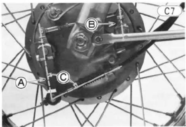
A. Primary Brake Cam Lever
B. Secondary Brake Cam Lever
C. 80 90°
- If they do not, remove the cam levers and then re-mount them at new positions on the shafts to achieve the proper angle, or loosen the locknut and turn the connecting rod to make the two cam levers parallel.
WARNING Since a cam lever angle greater than 90° reduces braking effectiveness, this adjustment should not be neglected. When remounting the cam, be sure that the position of the indicator on the serrated shaft is not altered. See Pg. 112 for detailed information on the position of the wear indicator when the cam lever is not on the shaft. A change in cam lever angle is caused by wear of internal brake parts. Whenever the cam lever angle is adjusted, also check for drag and proper lever operation, taking particular note of the brake lining wear indicator position. In case of doubt as to braking effectiveness, disassemble and inspect all internal brake parts. Worn parts could cause the brake to lock or fail.
- Rotate the wheel to check for brake drag.
- Operate the brake lever a few times to see that it returns to its rest position immediately upon release.
- Adjust the front brake lever.
Brake Shoe Synchronization
After the front wheel is removed, or after the brake was disassembled, synchronize the brake shoes.
- Raise the front wheel off the ground by some means.
- Loosen the locknut and turn the connecting rod one turn clockwise. This procedure backs off the secondary brake shoe so that it will not operate when the primary shoe contacts the inside surface of the drum.

A. Locknut
B. Connecting Rod
- While spinning the wheel lightly, turn in the adjusting nut and/or turn out the adjuster at the front brake lever until the primary shoe just starts touching the drum. When the shoe starts touching the drum, light dragging can be felt or heard.
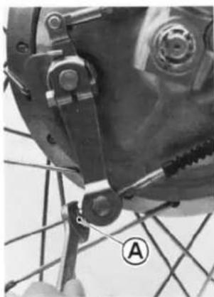
A. Adjusting Nut
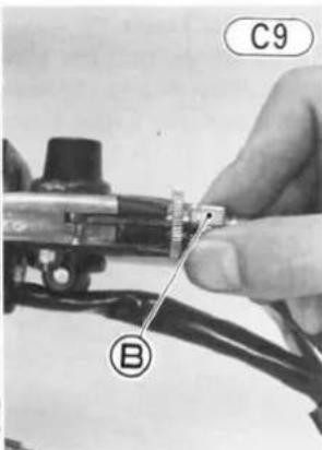
B. Adjuster
- Spinning the wheel lightly, turn the connecting rod counterclockwise until the secondary brake shoe just starts dragging on the drum, and then tighten the locknut.
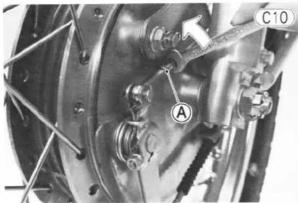
A. Locknut
- Adjust the front brake lever.
Front Brake Lever
- Loosen the knurled locknut at the front brake lever, turn the adjuster fully in, and tighten the locknut.
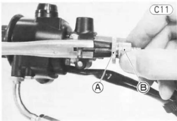
A. Knurled Locknut
B. Adjuster
- Turn the adjusting nut on the lower end of the front brake cable so that the brake lever will have 4 5 mm of play as shown in the figure.

A. 4\~5 mm
34 ADJUSTMENT-CHASSIS
- If sufficient adjustment cannot be made with the adjusting nut at the lower end of the brake cable, complete the adjustment with the adjuster at the brake lever, and then tighten the locknut.
- Check for brake drag.
- Operate the lever a few times to see that it returns to its rest position immediately upon release.
- For minor corrections, use the adjuster at the front brake lever.
Rear Brake
Brake lining and drum wear causes the rear brake to go out of adjustment, increasing pedal play and decreasing braking effectiveness. Rear brake adjustment to compensate for this actually consists of three successive adjustments: brake pedal position, cam lever angle, and brake pedal travel.
If brake drag is detected during brake adjustment, disassemble the brake (Pg. 119), and inspect for wear or damage (Pg. 202). Also, if the brake pedal does not return to its rest position quickly upon release, inspect the brake for wear or damage. If the brake has a soft or "spongy feeling", make sure the brake panel is properly centered. See the second "NOTE" in drive chain or belt adjustment procedure (Pg. 31 or 32).
On the outside of the rear brake panel there is a brake lining wear indicator. Whenever the indicator has gone past USABLE RANGE (Pg. 202), the brake shoes must be immediately replaced and the other brake parts examined. Adjustment alone cannot compensate for the wear of a brake worn past USABLE RANGE.
Brake Pedal Position
- When the brake pedal is in its rest position, it should be 0\~30 mm lower than the top of the footpeg. If it is too high, turn out the adjusting nut at the end of the brake rod to give the brake pedal plenty of play. If it is too low, go to the next step.

A. Adjusting Bolt C. Footpeg B. Locknut D. 0\~30 mm
- Loosen the brake pedal adjusting bolt locknut, turn the adjusting bolt to obtain the correct pedal position, and tighten the locknut.
- Check the brake pedal travel.
- Check the rear brake light switch operation.
Cam Lever Angle
- When the brake is fully applied, the brake cam lever should come to an 80\~90° angle with the brake rod.

A. 80 90°
- If it does not, remove the cam lever, and then remount it at a new position on the shaft for the proper angle.
WARNING Since a cam lever angle greater than 90° reduces braking effectiveness, this adjustment should not be neglected. When remounting the cam, be sure that the position of the indicator on the serrated shaft is not altered. See Pg. 120 for detailed information on the position of the wear indicator when the cam lever is not on the shaft. A change in cam lever angle is caused by wear of internal brake parts. Whenever the cam lever angle is adjusted, also check for drag and proper pedal operation, taking particular note of the brake lining wear indicator position. In case of doubt as to braking effectiveness, disassemble and inspect all internal brake parts. Worn parts could cause the brake to lock or fail.
- Rotate the rear wheel to check for brake drag.
- Operate the pedal a few times to see that it returns to its rest position immediately upon release.
- Adjust the brake pedal travel.
Brake Pedal Travel
- Check to see that the brake pedal has 20\~30 mm of travel from the rest position to the fully applied position when the brake pedal is pushed down lightly by hand.

A. Adjusting Nut

B. 20\~30 mm
- If it does not, turn the adjusting nut on the end of the brake rod so that the brake pedal has the proper travel.
- Rotate the rear wheel to check for brake drag.
- Operate the pedal a few times to see that it returns to its rest position immediately upon release.
- Check the rear brake light switch operation.
BRAKE LIGHT SWITCH
The front brake light switch mounted on the front brake lever holder is operated by simple electrical contact and should not need adjustment. However, the rear brake light switch, activated by a spring attached to the brake pedal, requires periodic adjustment to compensate for any change in spring tension or brake adjustment.
To check the brake light switch:
- With the ignition switch on, depress the brake pedal and note the brake pedal travel until the brake light goes on. The brake light should go on after 15 mm of pedal travel.
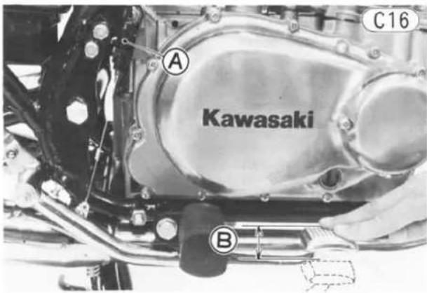
A. Brake Light Switch
B. 15 mm
To adjust the brake light switch:
●Turn the adjusting nut on the brake light switch body so that the brake light will go on after the proper amount of brake pedal travel. Raising the switch will make the light go on after less travel; lowering it will require more travel.
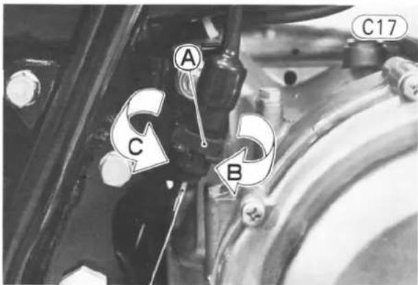
A. Adjusting Nut
C. Lights later
B. Lights sooner
CAUTION
To avoid damaging the electrical connections inside the switch, do not turn by during adjustment.
STEERING
For safety, the steering should always be kept adjusted so that the handlebar will turn freely but have no play.
If the steering is too tight, it will be difficult to turn the handlebar quickly, the motorcycle may pull to one side, and the steering stem bearings may become damaged. If the steering is too loose, the handlebar will vibrate and the motorcycle will be unstable and difficult to steer in a straight line.
To check the steering:
- Raise the front wheel off the ground.
- Push the handlebar lightly to either side; if it continues moving under its own momentum, the steering is not too tight.
- Squatting in front of the motorcycle, grasp the lower ends of the front fork at the axle, and push and pull the fork end back and forth; if play is felt, the steering is too loose.
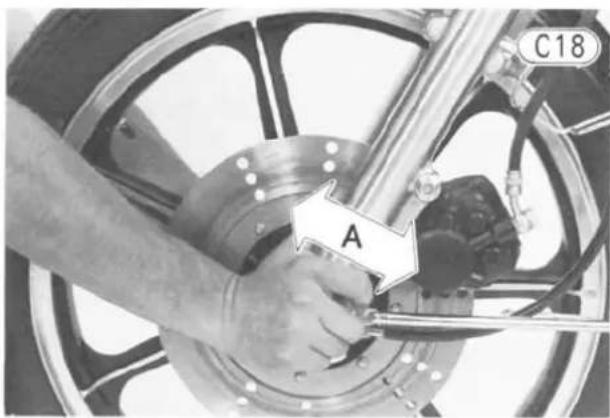
A. Push and pull
To adjust the steering:
- Remove the fuel tank (Pg.50) to avoid damaging the painted surface.
- Loosen the front fork lower clamp bolts (2) to free the fork tubes from the steering stem base during adjustment.

A. Lower Clamp Bolt
36 ADJUSTMENT-CHASSIS
- Loosen the steering stem head bolt and head clamp bolt, and back out the steering stem locknut using the stem nut wrench (special tool) 1 or 2 turns until it turns without drag.
NOTE: Do not back out the steering stem locknut more than a couple of turns. If the locknut is backed off too far, the bearing balls in the steering stem may fall out of place. This will necessitate steering stem removal and installation.
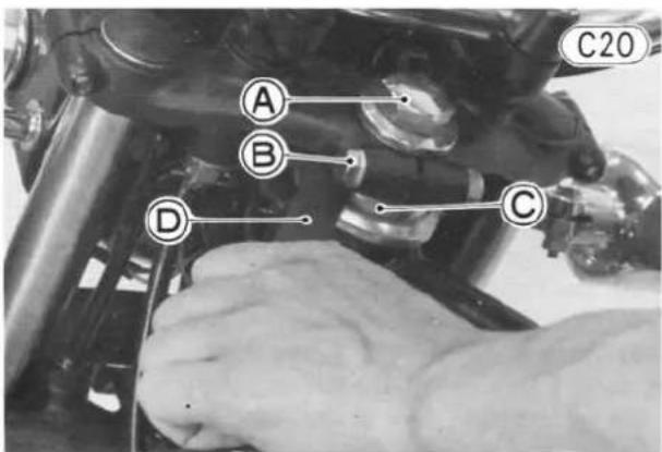
A. Stem Head Bolt
D. Stem Nut Wrench (57001-134 or -1100)
B. Head Clamp Bolt
C. Stem Locknut
- Using the stem nut wrench, tighten the stem locknut to 3.0 kg-m (22 ft-lbs) of torque.
NOTE: To tighten the steering stem locknut to the specified torque, firstly make a notch on the stem nut wrench at the 150 mm from the locknut center, secondly hook the wrench on the stem locknut, and then push the wrench at the notch by 20 kg force.

A. 150 mm
●Tighten the steering stem head bolt to 5.5 kg-m (40 ft-lbs) of torque.
●Tighten the steering stem head clamp bolt to 2.0 kg·m (14.5 ft·lbs) of torque.
● Tighten the front fork lower clamp bolts (2) to 3.0 kg-m (22 ft-lbs) of torque.
- Check the steering again. If the steering is too tight or too loose in spite of correct adjustment, inspect the steering stem parts according to the maintenance section (Pg. 204).
●Remount the fuel tank (Pg. 50).
WHEEL BALANCE
To improve stability and decrease vibration at high speed, the front and rear wheels must be kept balanced.
Check and balance the wheels when required, or when a tire is replaced with a new one.
To check the wheel balance:
- Remove the wheel (Pg. 107, 109, or 118).
- For a wire spoke wheel, check the all the spokes are tightened evenly and the rim runout is within the service limit (Pg. 193).
●Suspend the wheel so that it can be spun freely.
- Spin the wheel lightly, and mark the tire at the top when the wheel stops.
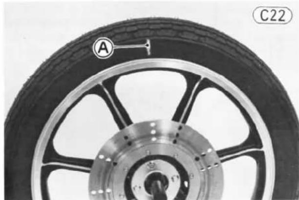
A. Mark at the top.
- Repeat this procedure several times. If the wheel stops of its own accord in various positions, it is well balanced.
●However, if the wheel always stops in one position, balance the wheel as follows.
To adjust wheel balance:
- Temporarily attach a balance weight on the wheel. For the cast wheel: Attach a balance weight on the rim at the marking with tape.
For the wire spoke wheel: Attach a balance weight loosely to the spoke under the marking.

A. Balance Weight
- Rotate the wheel 1/4 turn, and see whether or not the wheel stays in this position. If it does, the correct balance weight is being used.

A. Use heavier weight.
B. Use lighter weight.
- If the weighted location still stops at the top, try a heavier weight. If the weighted position always stops at the bottom, use slightly less weight. Repeat these steps until the wheel remains at rest after being rotated 1/4 turn.
- Rotate the wheel another 1/4 turn and then another 1/4 turn to see if the wheel is correctly balanced.
- Repeat the entire procedure as many times as necessary to achieve correct wheel balance.
●Install the balance weight firmly on the wheel. For the cast wheel: First reduce the tire pressure, pry the tire bead from the rim, and then insert the blade part of the balance weight between the rim and the tire bead until the stepped portions of the rim and the weight is hooked over the overhang portion of the rim.
Balance Weight Installation
C25

-
Tire
-
Blade
-
Rim
-
Weight
-
Tube
-
Tire Bead
For the wire spoke wheel: Clamp on the balance weight firmly using pliers.
- For the cast wheel, inflate the tire to standard pressure (Pg. 191).
●Reinstall the wheel back on the motorcycle (Pg. 107, 110, or 119).
NOTE: Balance weights are available from Kawasaki dealers in 10, 20, and 30 gram sizes. An imbalance of less than 10 grams will not usually affect running stability.
HEADLIGHT
The headlight beam is adjustable both horizontally and vertically. If not properly adjusted horizontally, the beam will point to one side rather than straight ahead. If adjusted too low vertically, neither low nor high beam will illuminate the road far enough ahead. If adjusted too high vertically, high beam will fail to illuminate the road close ahead, and low beam will blind oncoming drivers.
Horizontal Adjustment
(Except European Models)
- Turn the small screw on the headlight rim in or out until the beam points straight ahead. Turning the adjusting screw clockwise makes the headlight beam point to the left.

A. Adjusting Screw
Vertical Adjustment
●Loosen the headlight housing mounting bolts.

A. Mounting Bolt
38 ADJUSTMENT-CHASSIS
- Move the headlight up or down by hand to where the vertical aim is correct.
NOTE: On high beam, the brightest point should be slightly below horizontal. Adjust the headlight to the proper angle according to local regulations.

●Tighten the headlight housing mounting bolts.
AUTOMATIC SIDE STAND RETURN MECHANISM
Adjust the automatic side stand return mechanism whenever it does not work satisfactorily. If any damage to the mechanism is suspected or if it cannot be adjusted properly as explained below, consult the Maintenance Section (Pg. 210).
To check the mechanism:
●Swing down the side stand, and turn the rear wheel or walk the motorcycle. The side stand should return to its rest position when the rear wheel turns.
- Return the side stand to its rest position, and check that the pin on the engine sprocket does not hit the mechanism lever when the rear wheel rotates. The engine sprocket cover needs not be removed to check this tapping noise.
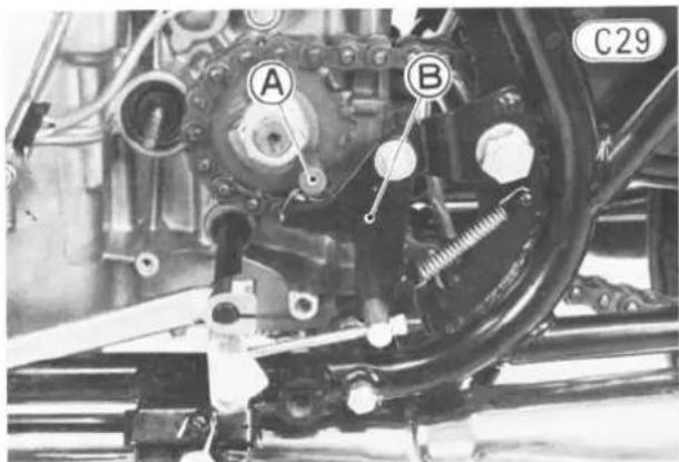
A. Pin B. Mechanism Lever
If any one of the above checks shows improper adjustment, or if there is a regular tapping noise from the mechanism when riding the motorcycle, adjust the mechanism.
To adjust the mechanism:
- Remove the rubber cap from the end of the rod.
- Turn the adjusting nut so that the proper adjustment is obtained. If the side stand does not return automatically, screw in the adjusting nut. If the pin hits the lever, screw out the adjusting nut.

A. Adjusting Nut
●Install the rubber cap on the end of the rod.
- Check the mechanism operation, and readjust if necessary.
LUBRICATION
Lubricate exposed parts which are subject to rust, with either motor oil or regular grease whenever the vehicle has been operated under wet or rainy conditions, and especially after using a high-pressure spray washer. Before lubricating each part, clean off any rusty spots with rust remover and wipe off any grease, oil, dirt, or grime.
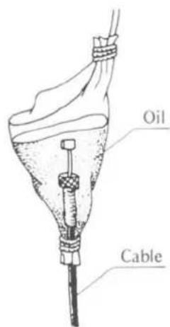
Clutch, Brake, and Throttle Cables
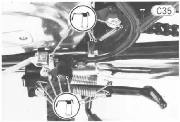
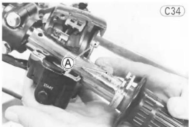
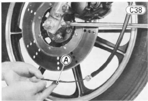
Lubricate the cables as shown in the figure. Refer to Pgs. 125\~127 for cable removal.
Cable Lubrication C31
Clutch and Brake Levers
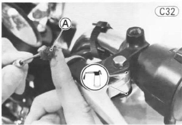
A. Grease
Left Footpeg, Side Stand,
Stand Return Mechanism

Throttle Grip
Apply grease to the handlebar where the throttle grip turns.
Apply a light coat of grease to the exposed portion of the throttle grip inner cables and their catches in the throttle grip.
Fit the throttle cables into the throttle grip. Refer to throttle cable installation (Pg. 126).
Center Stand

A. Grease
Right Footpeg, Brake Pedal, and Brake Rod

Speedometer and Tachometer Cables
Apply grease sparingly to the inner cables.
A. Grease
Brake Rod Joint

Brake Cam Lever Connecting Rod, Cable Joint
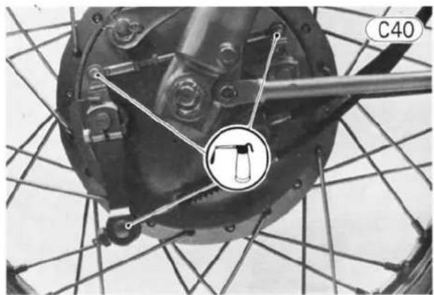
Carburetor Link Mechanism

Others
Lubricate the drive chain, wheel bearings, speedometer gear housing, swing arm pivot, and steering stem bearings as explained in the Maintenance Section.
NOTE: A few drops of oil are effective to keep bolts and nuts from rusting and sticking. This makes removal easier. Badly rusted nuts, bolt, etc. should be repalced with new ones.
Disassembly—Introduction
Table of Contents
INTRODUCTION TO DISASSEMBLY 42
TORQUE AND LOCKING AGENT.... 43

42 DISASSEMBLY-INTRODUCTION
INTRODUCTION TO DISASSEMBLY
Detail has not been spared in this chapter in order that the motorcycle can not only be taken apart but also put back together properly as well. Photographs, diagrams, notes, cautions, warnings, and detailed descriptions have been included wherever necessary. Nevertheless, even a detailed account has limitations; a certain amount of basic knowledge is also required for successful work.
Especially note the following:
(1) Edges
Watch for sharp edges, especially during major engine disassembly and assembly. Protect your hands with gloves or a piece of thick cloth when lifting the engine or turning it over.
(2) Dirt
Before removal and disassembly, clean the motorcycle. Any dirt entering the engine, carburetor or other parts will work as an abrasive and shorten the life of the motorcycle. For the same reason, before installing a new part, clean off any dust or metal fillings.
(3) Tightening Sequence
Where there is a tightening sequence indication in this Service Manual; the bolts, nuts, or screws must be tightened in the order and method indicated. When installing a part with several bolts, nuts, or screws; they should all be started in their holes and tightened to a snug fit. Then tighten them evenly, according to the tightening sequence, to the specified torque. This is to avoid distortion of the part and/or causing gas or oil leakage. Conversely when loosening the bolts, nuts, or screws; loosen all of them about a quarter of turn and then remove them.
(4) Torque
The torque values given in this Service Manual should always be adhered to. Either too little or too much torque may lead to serious damage. Use a good quality, reliable torque wrench.
(5) Force
Common sense should dictate how much force is necessary in assembly and disassembly. If a part seems especially difficult to remove or install, stop and examine what may be causing the problem. Whenever tapping is necessary, tap lightly using a wooden or plastic-faced mallet. Use an impact driver for screws (particularly for the removal of screws held by a locking agent) in order to avoid damaging the screw heads.
(6) Lubricant
Don't use just any oil or grease. Some oils and greases in particular should be used only in certain applications and may be harmful if used in an application for which they are not intended.
(7) Battery Ground
Before performing any disassembly operations on the motorcycle, remove the ground (—) lead from the battery to prevent the possibility of accidentally turning the engine over while partially disassembled.
(8) Engine Rotation
When turning the crankshaft by hand, always turn it in the direction of normal rotation; which is counterclockwise, viewed from the right side of the engine. This will ensure proper adjustments.
(9) Lubrication
Engine wear is generally at its maximum while the engine is warming up and before all the rubbing surfaces have an adequate lubricative film. During assembly, oil or grease (whichever is more suitable) should be applied to any rubbing surface which has lost its lubricative film. Old grease and dirty oil should be cleaned off. Deteriorated grease has lost its lubricative quality and may contain abrasive foreign particles.
(10) Press
A part installed using a press or driver, such as a wheel bearing, should first be coated with oil on its outer or inner circumference so that it will go into place smoothly.
(11) Oil Seal, Grease Seal
Replace any oil or grease seals that were removed with new ones, as removal generally damages seals. A seal guide is required for certain oil or grease seals during installation to avoid damage to the seal lips. Before a shaft passes through a seal, apply a little oil, preferably high temperature grease on the lips to reduce rubber to metal friction.
(12) Gasket, O Ring
When in doubt as to the condition of a gasket or O ring, replace it with a new one. The mating surfaces around the gasket should be free of foreign matter and perfectly smooth to avoid oil or compression leaks.
(13) Liquid Gasket, Non-permanent Locking Agent
Follow manufacturer's directions for cleaning and preparing surfaces where these compounds will be used. Apply sparingly. Excessive amounts may block engine oil passages and cause serious damage. An example of a non-permanent locking agent commonly available in North America is Lock'n Seal (Blue).
(14) Ball Bearing, Oil Seal, Grease Seal Installation
When installing a ball bearing, the bearing race which is affected by friction should be pushed by a suitable driver. This prevents severe stress on the balls and races, and prevents races and balls from being dented. Press a ball bearing until it stops at the stop in the hole or on the shaft. Seals should be pressed into place using a suitable driver, which contacts evenly with the side of the seal until the face of the seal is even with the end of the hole.
(15) Circlip, Retaining Ring
Replace any circlips and retaining rings that were removed with new ones, as removal weakens and deforms them.
When installing circlips and retaining rings, take care to compress or expand them only enough to install them and no more.
(16) High Flash-point Solvent
A high flash-point solvent is recommended to reduce fire danger. A commercial solvent commonly available in North America is Stoddard solvent (generic name). Always follow manufacturer and container directions regarding the use of any solvent.
(17) Molybdenum Disulfide (MoS2) Grease
This manual makes reference to molybdenum disulfide grease in the assembly of certain engine and chassis parts. Always check manufacturer recommendations before using such special lubricants.
(18) Electrical Leads
All the electrical leads are either single-color or two-color and, with only a few exceptions, must be connected to leads of the same color. On any of the two-color leads there is a greater amount of one color and a lesser amount of a second color, so a two-color lead is identified by first the primary color and then the secondary color. For example, a yellow wire with thin red stripes is referred to as a "yellow/red" wire; it would be a "red/yellow" wire if the colors were reversed to make red the main color.
TORQUE AND LOCKING AGENT
Tighten all bolts and nuts to the proper torque using an accurate torque wrench. If insufficiently tightened, a bolt or nut may become damaged or fall off, possibly resulting in damage to the motorcycle and injury to the rider. A bolt or nut which is overtightened may become damaged, strip an internal thread, or break and then fall out. The following table lists the tightening torque for the major bolts and nuts, and the parts requiring use of a non-permanent locking agent.
Parts marked with an asterisk (*) must be retorqued according to the Periodic Maintenance Chart (Pg. 16). One at a time, loosen each bolt or nut 1/2 turn, then tighten it to the specified torque. Follow the sequence if specified. For engine fasteners, retorque them when the engine is cold (at room temperature).
NOTE: Marks used in "Remark"
- : Apply a non-permanent locking agent to the threads.
★: Apply a liquid gasket to the threads or washer.
| Engine Part | Quantity | Metric (kg-m) | English (ft-lbs) | Remark | See Pg. |
| Alternator rotor Allen bolts M6 P1.0 | 3 | 1.0 | 87 in-lbs | ● | 72 |
| Alternator rotor bolt M10 P1.25 | 1 | 7.0 | 51 | - | 72,95 |
| Balancer chain guide screws M6 P1.0 | 3 | - | - | ● | 101 |
| Balancer weight bolts M6 P1.0 | 2 | 1.5 | 11.0 | - | 102 |
| Breather cover bolts M8 P1.25 | 4 | 2.5 | 18.0 | ● | 58 |
| Camshaft cap bolts M6 P1.0 | 6 | 1.2 | 104 in-lbs | - | 61,156 |
| Camshaft chain tension lock bolt M6 P1.0 | 1 | 1.0 | 87 in-lbs | - | 60 |
| Camshaft oil receiver screws M6 P1.0 | 2 | - | - | ● | 60 |
| Camshaft sprocket bolts M6 P1.0 | 2 | 1.5 | 11.0 | ● | 61 |
| Carburetor holder screws M6 P1.0 | 4 | - | - | ● | - |
| Clutch spring bolts M6 P1.0 | 4 | 0.9 | 78 in-lbs | - | 80 |
| Connecting rod big end cap nuts M8 P0.75 | 4 | 3.7 | 27 | - | 104,168 |
| Crankcase bolts | |||||
| lower M6 P1.0 | 11 | 1.0 | 87 in-lbs | - | 94,169 |
| M8 P1.25 | 4 | 2.5 | 18.0 | - | 94,169 |
| upper M6 P1.0 | 5 | 1.0 | 87 in-lbs | - | 94,169 |
| Crankshaft main bearing cap bolts | |||||
| M10 P1.5 | 4 | 4.0 | 29 | - | 93,100,169 |
| M8 P1.25 | 4 | 2.5 | 18.0 | - | 93,100,169 |
| Crankshaft oil passage plugs M6 P1.0 | 2 | - | - | ● | - |
| Cylinder head nuts M10 P1.25 | 8 | 4.0 | 29 | - | 62 |
| *Cylinder head cover bolts M8 P1.25 | 8 | 2.5 | 18.0 | - | 58 |
| M6 P1.0 | 8 | 1.0 | 87 in-lbs | - | 58 |
| Drive chain guard screws M6 P1.0 | 4 | - | - | ● | 70 |
| Engine drain plug M12 P1.5 | 1 | 3.0 | 22 | - | 27,84,88 |
| *Engine mounting bolts M10 P1.25 | 4 | 4.0 | 29 | - | 90 |
| Engine mounting bracket bolts front & rear M8 P1.25 | 5 | 2.5 | 18.0 | - | 90 |
| upper M8 P1.25 | 3 | 2.5 | 18.0 | - | 58,90 |
| Engine sprocket (or pulley) nut M20 P1.5 | 1 | 8.5 | 61 | - | 71,95 |
| *Exhaust pipe holder nuts M6 P1.0 | 4 | - | - | - | 57 |
| Neutral switch M10 P1.25 | 1 | 1.5 | 11.0 | - | 70 |
| Oil filter mounting bolt M20 P1.5 | 1 | 2.0 | 14.5 | - | 84,88 |
| Oil passage plugs on lower crankcase PT 1/8 | 1 | 1.0 | 87 in-lbs | ★ | - |
| PT 1/4 | 2 | 3.0 | 22 | ★ | - |
| on main bearing cap Allen screw M6 P1.0 | 1 | - | - | ★ | - |
| hex head bolts M6 P1.0 | 2 | 1.0 | 87 in-lbs | - | - |
| Oil pipe fitting bolts M10 P1.25 | 2 | 2.0 | 14.5 | - | 63,68,95 |
| Oil pressure switch PT 1/8 | 1 | 1.5 | 11.0 | - | 69 |
| Oil pressure relief valve M12 P1.25 | 1 | 1.5 | 11.0 | ● | 82 |
| Primary chain guide screws M6 P1.0 | 2 | - | - | ● | 78 |
| Return spring pin M8 P1.25 | 1 | - | - | ● | 179 |
| Rocker shaft M16 P1.5 | 4 | 4.0 | 29 | - | 58 |
| Shift drum positioning bolt M16 P1.5 | 1 | 3.5 | 25 | - | 97 |
| Shift shaft stop screws M6 P1.0 | 2 | - | - | ● | 83 |
| Spark plugs M14 P1.25 | 2 | 2.8 | 20 | - | 18 |
| Starter motor chain guide screws M5 P0.80 | 2 | - | - | ● | 72 |
| Starter motor clutch Allen bolts M8 P1.25 | 3 | 3.5 | 25 | ● | 73 |
| Starter motor retaining bolts M6 P1.0 | 2 | 1.0 | 87 in-lbs | ● | 74,95 |
| Stud bolts cylinder M10 P1.5 | 8 | - | - | ● | - |
| exhaust - M6 P1.0 | 4 | - | - | ● | - |
| Sump plate screws M6 P1.0 | 4 | - | - | ● | 93 |
| Timing advancer bolt M8 P1.25 | 1 | 2.5 | 18.0 | - | 77,95 |
| Valve clearance adjusting screw locknuts M6 P0.75 | 4 | 1.5 | 11.0 | - | 21 |
| Chassis Part | Quantity | Metric (kg-m) | English (ft-lbs) | Remark | See Pg. |
| *Brake cam lever bolt | 1 | - | - | - | - |
| *Brake pedal mounting nut (or bolt) M8 P1.25 | 1 | 2.1 | 15.0 | - | - |
| *Clutch lever holder bolt M6 P1.0 | 1 | - | - | - | - |
| *Disc brake parts | See Table G1 on Pg. 113. | ||||
| *Front axle clamp nuts M8 P1.25 | 2 | 2.0 | 14.5 | - | 110 |
| *Front axle nut M16 P1.5 | 1 | 6.5 | 47 | - | 107 |
| M14 P1.5 | 1 | 6.5 | 47 | - | 110 |
| *Front fender mounting bolts M8 P1.25 | 4 | - | - | - | - |
| *Front footpeg mounting bolts | 2 | - | - | - | - |
| Front fork bottom Allen bolts M10 P1.0 | 2 | 1.8 | 13.0 | •,★ | 141 |
| *Front fork clamp bolts upper M8 P1.25 | 2 | 2.0 | 14.5 | - | 141 |
| lower M10 P1.25 | 2 | 3.0 | 22 | - | 29,141 |
| Handlebar clamp bolts M8 P1.25 | 4 | 2.1 | 15.0 | - | 135 |
| *Rear axle nut M16 P1.5 | 1 | 7.5 | 54 | - | 32 |
| *Rear footpeg (muffler) mounting bolts | 2 | - | - | - | 56 |
| *Rear shock absorber mounting bolts M10 P1.25 | 2 | 3.3 | 24 | - | 119 |
| nuts M10 P1.25 | 2 | 3.3 | 24 | - | - |
| Rear sprocket (or pulley) nuts M10 P1.25 | 4 | 3.3 | 24 | - | 122 |
| *Shift pedal bolt M6 P1.0 | 1 | - | - | - | - |
| Spokes | 76 | 0.30 | 26 in-lbs | - | 125,192 |
| *Steering stem head bolt M16 P1.5 | 1 | 5.5 | 40 | - | 36,138 |
| *Steering stem head clamp bolt M8 P1.25 | 1 | 2.0 | 14.5 | - | 36,138 |
| Steering stem locknut M30 P1.0 | 1 | 3.0 | 22 | - | 36,138 |
| *Swing arm pivot shaft nut M14 P1.5 | 1 | 9.0 | 65 | - | 142 |
| *Torque link nuts M10 P1.25 | 2 (4) | 3.3 | 24 | - | 32,110,143 |
The table below, relating tightening torque to thread diameter and pitch, lists the basic torque for the bolts and nuts used on Kawasaki Motorcycles. However, the actual torque that is necessary may vary among bolts and nuts with the same thread diameter and pitch. The bolts and nuts listed on Pg. 43\~45 vary to a greater or lesser extent from what is given in this table. Refer to this table for only the bolts and nuts not included in the table on Pg. 43\~45. All of the values are for use with dry solvent-cleaned threads.
Coarse threads
| dia (mm) | pitch (mm) | kg-m | ft-lbs |
| 5 | 0.80 | 0.35~0.50 | 30~43 in-lbs |
| 6 | 1.00 | 0.60~0.90 | 52~78 in-lbs |
| 8 | 1.25 | 1.6~2.2 | 11.5~16.0 |
| 10 | 1.50 | 3.1~4.2 | 22~30 |
| 12 | 1.75 | 5.4~7.5 | 39~54 |
| 14 | 2.00 | 8.3~11.5 | 60~83 |
| 16 | 2.00 | 13.0~18.0 | 94~130 |
| 18 | 2.50 | 18.0~25 | 130~181 |
| 20 | 2.50 | 26~35 | 188~253 |
Fine threads
| dia (mm) | pitch (mm) | kg-m | ft-lbs |
| 5 | 0.50 | 0.35~0.50 | 30~43 in-lbs |
| 6 | 0.75 | 0.60~0.80 | 52~69 in-lbs |
| 8 | 1.00 | 1.4~1.9 | 10.0~13.5 |
| 10 | 1.25 | 2.6~3.5 | 19.0~25 |
| 12 | 1.50 | 4.5~6.2 | 33~45 |
| 14 | 1.50 | 7.4~10.2 | 54~74 |
| 16 | 1.50 | 11.5~16.0 | 83~116 |
| 18 | 1.50 | 17.0~23 | 123~166 |
| 20 | 1.50 | 23~33 | 166~239 |
Disassembly—Engine Installed
Table of Contents
FLOW CHART 48
AIR CLEANER ELEMENT 49
FUEL TANK 50
FUEL TAP 51
IGNITION COIL. 52
CARBURETORS 52
MUFFLERS 56
TOP END
CYLINDER HEAD COVER, ROCKER ARM, ROCKER SHAFT.....57
CAMSHAFT CHAIN TENSIONER 58
CAMSHAFT, CAMSHAFT SPROCKET.... 60
CYLINDER HEAD 62
VALVE, VALVE GUIDE.... 63
CYLINDER BLOCK.... 65
CAMSHAFT CHAIN GUIDE (Rear).... 66
PISTON, PISTON RINGS.... 66
OIL PIPE 68
OIL PRESSURE SWITCH 68
LEFT SIDE
ENGINE SPROCKET (or PULLEY) COVER....69
CLUTCH RELEASE....70
NEUTRAL SWITCH....70
ENGINE SPROCKET (or PULLEY)....70
ALTERNATOR STATOR 71
ALTERNATOR ROTOR, STARTER MOTOR CLUTCH ..... 72
STARTER MOTOR CHAIN, SPROCKETS 73
STARTER MOTOR 74
RIGHT SIDE
CONTACT BREAKER....76
CAPACITOR....77
TIMING ADVANCER 77
PRIMARY CHAIN GUIDES. 78
CLUTCH, PRIMARY CHAIN, PRIMARY SPROCKET....78
OIL PUMP DRIVE GEAR 81
OIL PUMP 81
OIL PRESSURE RELIEF VALVE....82
EXTERNAL SHIFT MECHANISM 82
BOTTOM END
OIL FILTER, BYPASS VALVE....84
This chart is intended to be aids to proper removal. Select the component you wish to remove and follow the arrows to that point on the chart.
FLOW CHART
Disassembly – Engine Installed
![graph TD A["Motorcycle"] --> B["Left Side"] A --> C["Top End"] A --> D["Bottom End"] A --> E["Right Side"] B --> F["Drive Chain (or Belt)"] B --> G["Left Footpeg"] B --> H["Automatic Side Stand Return Mechanism"] B --> I["Engine Sprocket (or Pulley) Cover"] B --> J["Engine Sprocket (or Pulley)"] B -…](/content/2026/06/1261528/images/4b1737297be89aa7a978a5c210805440d2f7bdf53950ca5dbf9371dd37ea28bd.jpg)
NOTES: 1. Before performing any disassembly operations, remove the ground (—) lead from the battery to prevent the possibility of accidentally turning the engine over. 2. Action with a mark (*) requires special tool(s) for removal, installation, disassembly, or assembly. 3. The part in the broken line is required to remove its mounting bolts, but not necessary its complete removal.
AIR CLEANER ELEMENT Removal (KZ440B, C):
- Unlock the seat, and swing it open.
- Remove the tool kit, and remove its tray retaining screw, lockwasher, and flat washer.

A. Tray
B. Retaining Screw
●Take off the tray, and pull out the air cleaner element.

A. Air Cleaner Element
Installation (KZ440B, C):
●Taking care not to push the sponge gasket out of place, install the air cleaner element to push the element until it stops at the bottom of the air cleaner housing, and push the upper part of the element towards the front. The open side of the air cleaner element must face to the front.
NOTE: When properly installed, the projection in the air cleaner housing hangs over the element upper end as shown in Fig. E3, and the sponge gasket securely contacts against the front wall of the air cleaner housing.
- Install the tool tray with the screw. The screw has a flat washer and lockwasher. Be sure that the stop on the bottom of the tray goes to the rear of the element (Fig. E3). It keeps the element from moving towards the rear.
- Put the tool kit in its tray, and push back the seat.
Air Cleaner Element Installation
E3
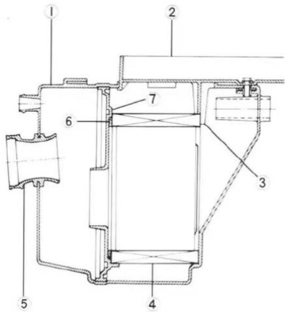
- Air Cleaner Housing
- Air Cleaner Duct
- Tray
- Sponge Gasket
- Stop
- Projection
- Element
Removal (KZ440A, D):
- Unlock the seat, and swing it open.
●Unscrew the mounting screws and flat washers (2 ea), and take off the air cleaner body.

A. Air Cleaner Body
B. Mounting Screws
●Pull out the element.
●Unhook the sponge filter at both ends, and remove it from the wire frame.

A. Sponge Filter
B. Wire Frame
Installation Note (KZ440A, D):
●Fit the ridge of the air cleaner body into the groove in the air cleaner housing, and secure the mounting screws (2).
Air Cleaner Body Installation
E6
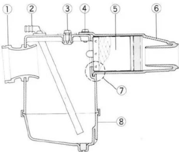
- Air Cleaner Duct
- Air Cleaner Body
- Breather Hose Fitting
- Fit the ridge into the groove.
- Housing Mount Bolts
- Air Cleaner Housing
- Body Mounting Screws
5.. Air Cleaner Element
FUEL TANK
Removal:
- Turn the fuel tap to the "ON" or "RES" position, slide the hose clamps down, and pull the fuel hose and vacuum hose off the tap.
- Unlock the seat and swing it open.
●Lift the rear end of the fuel tank up about 30 mm and then pull the fuel tank off toward the rear.
●On models where equipped, unscrew the tank mounting screw.

A. Lift
B. Pull
Installation:
●Install the fuel tank. Be sure the retaining projection is seated in the retaining rubber hole (Fig. E8).

A. Retaining Projection
B. Retaining Rubber
●Fit the fuel hose and vacuum hose back onto the fuel tap, and slide the hose clamps back into place. The vacuum hose has a smaller diameter than the fuel hose.

A. Clamp
B. Fuel Hose
C. Vacuum Hose
●Push the seat back down.
FUEL TAP
Removal:
- Run the ends of the overflow tubes into a suitable container, and turn the tap to the "PRI" position.
- Loosen the drain screws to drain the tank through the overflow tubes until no fuel comes out, and then tighten the drain screws.

A. Drain Screw
B. Overflow Tube
- Slide the hose clamps out of position, and pull the fuel and vacuum hoses off the tap.
- Remove the bolts and gaskets, and pull the fuel tap with O ring off the fuel tank. Be careful not to damage the filter.
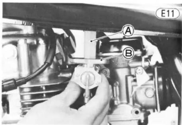
A. Filter
B. "O" Ring
Installation Notes:
- Check the O ring, and replace it with a new one if it is damaged or deteriorated.
- After installing the fuel tap on the tank, make sure that the fuel stops when the engine stops.
- The vacuum hose is the small diameter hose; the fuel hose is larger.

A. Vacuum Hose
B. Fuel Hose
Disassembly:
- Remove the screws (2), and remove the tap lever, wave washer, and holding plate.

A. Holding Plate
C. Tap Lever
B. Wave Washer
D. Valve Gasket
●Take out the valve gasket.
- Remove the screws (4), and remove the diaphragm cover and spring.
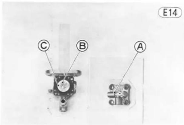
A. Diaphragm Cover
C. Diaphragm Assembly
B. Spring
- Remove the diaphragm assembly from the fuel tap.
52 DISASSEMBLY-ENGINE INSTALLED
Assembly Notes:
- Check and clean all the parts (Pg. 147). Replace damaged parts with new ones.
- Install the diaphragm cover in the direction shown in Fig. E14, marking sure that the spring is compressed at the center of the diaphragm between the diaphragm and the cover.
- Install the valve gasket in aligning its holes with the holes in the body.


A. Collar
Installation Notes:
- Use only the Kawasaki ignition coil bolts to mount the ignition coil. Bolts of a different composition may adversely affect ignition coil performance.
- Run the right spark plug lead between the upper brackets.
IGNITION COIL
Removal:
- Remove the fuel tank (Pg. 50).
●Pull the spark plug leads off the spark plugs. - Disconnect the blue and yellow/red leads of the ignition coil.

A. Ignition Coil
- Remove the bolts (2) that connect the ignition coil to the bracket, and remove the ignition coil. Each bolt has a collar between the ignition coil and the bracket.
CARBURETORS
Removal:
- Remove the fuel tank (Pg. 50).
●Take off the right and left side covers.
●Pull off the oil pressure switch lead so that it does not get damaged during carburetor removal. - Loosen both carburetor holder clamps, and slip them out of place.
- Slide both spring bands of the air cleaner ducts out of place.
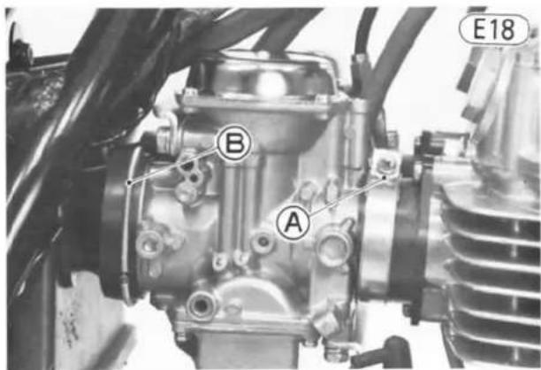
A. Carburetor Holder Clamp
B. Spring Band
- Loosen the locknut of the throttle cable adjuster, screw the adjuster out of its bracket, and slip the tip of its inner cable out of the pulley.
- Slip the carburetors up and out of them to the right side.
Installation Notes:
- If the carburetors were disassembled, visually syn- chronize the throttle (butterfly) valves as follows:
○Check to see that both butterfly valves open and close smoothly without no binding when turning the pulley.
- Visually check the clearance between the butterfly and the carburetor bore in each carburetor.

A. Clearance
C. Balance Adjusting Screw
B. Locknut
If both clearance differ from each other, loosen the locknut, and turn the balance adjusting screw to obtain the same clearance.
◦Tighten the locknut.
- Adjust the throttle cable (Pg. 21).
- Adjust the carburetors (Pg. 22).
Carburetor Body Disassembly (each carburetor):
NOTE: The following procedure explains removal of the carburetor parts listed below, and these parts can be removed without separating the carburetors from the mounting plates.
Vacuum Piston
Needle Jet Holder
Jet Needle
Float
Pilot Screw
Float Valve Needle
Primary Main Jet
Needle Jet
Main Jet Bleed Pipe
Pilot Jet
Secondary Main Jet
Top End:
- Remove the upper chamber cover screws (4), and take off the upper chamber cover 54 and spring 55.
●Pull out the vacuum piston 59 with the diaphragm.
CAUTION
During carburetor disassembly, be careful not to damage the diaphragm. Never use
a sharp edge to remove the diaphragm.
●Unscrew the holding screw 56, and remove the jet needle 57.
- To remove the pilot screw 42 on the US model carburetor, punch and pry off the plug 41 with an owl or other suitable tools, turn in the pilot screw and count the number of turns until it seats fully but not tightly, and then remove the pilot screw, spring 43, washer 44, and O ring 45. This is to set a pilot screw on its original position when assembling.
Bottom End:
- Remove the screws 52 and lockwashers 51 (4 ea), and take off the float bowl 69 and O ring 68.
- Now, the primary main jet 41, main jet bleed pipe 46, secondary main jet 63, and needle jet holder 62 can be removed.
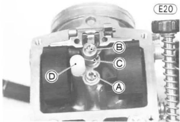
A. Primary Main Jet
C. Needle Jet Holder
B. Secondary Main Jet
D. Plastic Plug
- To remove the float valve needle 64 , first push out the float pin 67 , remove the float 66 , and pull out the float valve needle with its hanger clip 65 .
- To remove the needle jet 61, remove the vacuum piston (see above) and needle jet holder.
- To remove the pilot jet 48, remove the plastic plug 50 with the O ring 49.
Carburetor Body Assembly Notes (each carburetor):
- Replace any O ring and plastic plug if damaged or deteriorated.
- Assemble the upper chamber as follows:
Insert the spring into the vacuum piston.
- Fit the vacuum piston into the carburetor body, and check that the piston slides up and down without drag.
○Align the diaphragm tongue with the notch in the upper chamber cover mating surface, and fit the diaphragm sealing lip into its groove.

A. Tongue
B. Notch
54 DISASSEMBLY—ENGINE INSTALLED
With a finger, lift the vacuum piston just enough so that there is no crease on the diaphragm, and taking care not pinch the diaphragm lip, install the upper chamber cover. While holding the cover to keep it from being lifted by the spring, tighten the screws (4 ea).
CAUTION If the diaphragm is pinched, not only does the diaphragm become damaged, but the vacuum piston will not slide down to the rest position (there is a 7 mm space normally left between the piston lower end and the carburetor venturi). This causes idling unstability and reduces engine performance.
○After installing the upper chamber cover, check that the vacuum pistons slide up and down smoothly without binding in the carburetor bores.
- When assembling the float valve needle, hook its hanger clip to the tang on the float.

A. Valve Needle
B. Tang
- For the US model carburetor, install the pilot screw and plug as follows:
Turn in the pilot screw fully but not tightly, and then back it out the same number of turns counted during disassembly.
○Install a new plug in the pilot screw hole, and apply a small amount of a bonding agent to the circumference of the plug to fix the plug.
Plug Installation
E23
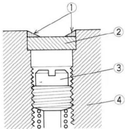
-
Apply a bonding agent.
-
Pilot Screw
-
Pilot Screw Plug
-
Carburetor Body
CAUTION being fixed.
Do not apply too much bond on the plug to keep the pilot screw itself from
Separation of Carburetors:
- Unhook the end of the choke link spring 21 from the lever on the right choke valve shaft.

A. Choke Link Spring
- Remove the screws and lockwashers (4 ea) to take off the upper mounting plate ①.
- Remove the screws and lockwashers (4 ea) to take off the lower mounting plate 7 and separate the left and right carburetors. The linkage mechanism spring 40 and fuel hose 3-way joint 36 come off.
Assembly:
- Install the upper and lower mounting plates to one of the carburetors. The lower mounting plate must be installed as shown in the figure.

A. Lower Mounting Plate
B. Upper Mounting Plate
- Check that the O rings (2) are in place, and install the long pipe of the fuel hose 3-way joint to the left carburetor.
Carburetors
E26
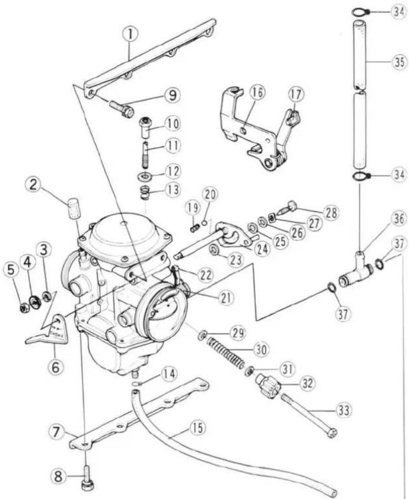
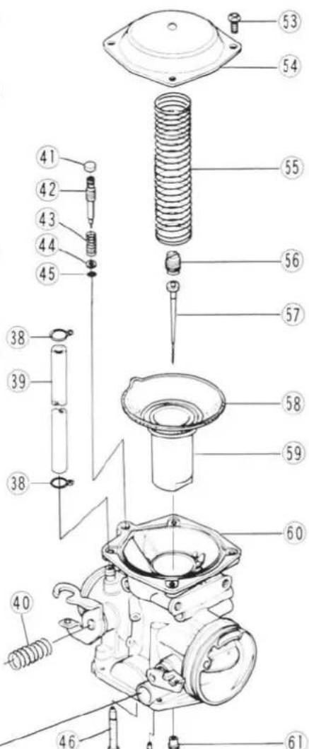
-
Upper Mounting Plate
-
Cap
-
Lockwasher
-
Washer
-
Nut
-
Choke Lever
-
Lower Mounting Plate
-
Bolt
-
Bolt
-
Locknut
-
Balance Adjusting Screw
-
Washer
-
Spring
-
Clip
-
Overflow Tube
-
Cable Bracket
-
Fast Idle Link
-
Screw
-
Spring
-
Ball
-
Choke Link Spring
-
Choke Link
-
Flat Washer
-
Fast Idle Cam
-
Flat Washer
-
Flat Washer
-
Wave Washer
-
Bolt
-
Washer
-
Spring
-
Washer
-
Knob
-
Idle Adjusting Screw
-
Clip
-
Fuel Hose
-
3-way Joint
-
O Ring
-
Clip
-
Vacuum Hose
-
Spring
-
Plug
-
Pilot Screw
-
Spring
-
Washer
-
O Ring
-
Bleed Pipe
-
Primary Main Jet
-
Pilot Jet
-
O Ring
-
Plastic Plug
-
Lockwasher
-
Screw
-
Screw
-
Upper Chamber Cover
-
Spring
-
Holding Screw
-
Jet Needle
-
Diaphragm
-
Vacuum Piston
-
Carburetor Body
-
Needle Jet
-
Needle Jet Holder
-
Secondary Main Jet
-
Float Valve Needle
-
Hanger Clip
-
Float
-
Float Pin
-
O Ring
-
Float Bowl
-
Drain Screw
-
O Ring
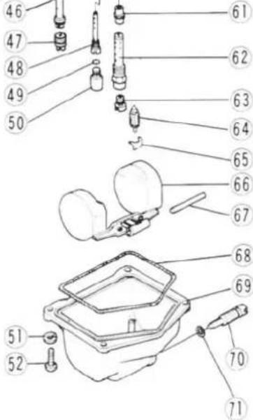
- Install the linkage mechanism spring as shown in the figure.

A. Spring
●Install the other carburetor on the mounting plate.
●Hook the end of the choke link spring on the lever.
Fast Idle Mechanism Adjustment
- Adjust the idle speed to 1,100\~1,300 rpm by turning the idle adjusting screw (Pg. 23).
- Check that there is 4\~6 mm clearance between the pin on the idling link and the fast idle cam when the choke lever is fully pushed down as shown in Fig. E28.
Fast Idle Mechanism

- Choke Link
- Butterfly Valve
- Fast Idle Cam
- Pulley
- Fast Idle Link
- Idle Adjusting Screw
- If the clearance is not within the specified value, narrow or spread the gap in the idling link to adjust the clearance.
MUFFLERS
Removal:
- For the muffler of 2 into 2 type, loosen the clamps that secure the mufflers to the muffler connecting pipe, and slide the connecting pipe toward the left.

A. Clamps
B. Muffler Connecting Pipe
- For the muffler of 2 into 1 type, loosen the exhaust pipe clamp bolt.
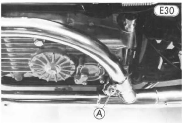
A. Clamp Bolt
- Remove the exhaust pipe holder nuts (4), and slide both left and right holders off the cylinder head studs.

A. Exhaust Pipe Holder
B. Nuts
- Remove the split keepers.
- Remove the left and right rear footpeg mounting bolts to complete muffler removal. Also, remove the exhaust pipe holders and gaskets. The rear footpeg mounting bolt has a footpeg, flat washer, lockwasher, and nut.
Installation:
●Fit the connecting pipe to the left muffler.
●Fit a new gasket into each exhaust port, and place an exhaust pipe holder on the stud bolts on each side.
●Fit the end of the exhaust pipe into each exhaust port, and attach the mufflers to the frame with the rear footpeg mounting bolts finger tight.
- Connect both mufflers with the connecting pipe, and move the connecting pipe until it stops at the stop of the right muffler manifold. Tighten the clamp bolts loosely.
●Fit the split keepers back into place, holder them in place with the exhaust pipe holders, tighten the holder nuts evenly to avoid an exhaust leak, and then tighten the rear footpeg mounting bolts.
●Tighten the clamp bolts of the muffler connecting pipe.
- Remove the contact breaker cover and gasket.
- Using a 17 mm wrench on the crankshaft, turn the crankshaft until the "T" mark on the timing advancer is aligned with the timing mark.
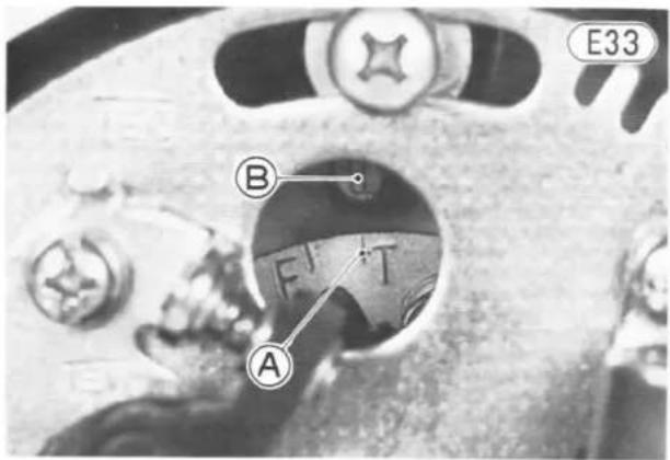
A. "T" Mark
B. Timing Mark
CYLINDER HEAD COVER, ROCKER ARM, ROCKER SHAFT
Removal:
- Remove the fuel tank (Pg. 50).
●Disconnect the blue and the yellow/red ignition coil leads. - Remove the bolts (2), and take the ignition coil off the frame together with its mounting bracket.
- Remove the upper bracket bolts and nuts (3 ea), and take off the brackets.

A. Nuts
B. Upper Brackets
C. Breather Hose
- Slide the clip out of place, and pull the breather hose off the breather cover.
- Remove the breather cover bolts (4), and take off the breather cover and O ring.
- Remove the tachometer cable from the cylinder head cover. Remove the screw, and remove the tachometer pinion holder stop. Pull out the tachometer pinion holder and pinion.

Attempting to install the cylinder head cover with the tachometer pinion left in cause tachometer gear damage.

A. Screw B. Stop
C. Tachometer Pinion Holder
- Remove the cylinder head cover 8 mm bolts (8) and 6 mm bolts (8).
- With a wide screwdriver, pry at the gap in the front side of the cylinder head cover to free the cylinder head cover from the cylinder head.
Do not hammer on the screwdriver while it is in the pry point as engine damage - Remove the rocker shaft and washer, and take off the rocker arm.

could result.
58 DISASSEMBLY-ENGINE INSTALLED
Cylinder Head Cover Pry Point
E35

Bad

Good

A. Rocker Arm
B. Rocker Shaft
C. Washer
Installation:
- Apply a little engine oil to the rocker shaft, insert the shaft running it through the rocker arm, and tighten the rocker shaft to 4.0 kg-m (29 ft-lbs) of torque. The rocker shaft has a washer.
- With a high flash-point solvent, clean off the mating surfaces of the cylinder head and cylinder head cover, and wipe dry.
- Check that the tachometer pinion is removed from the cylinder head cover, and cylinder head cover knock pins (2) are fitted.
- Check that the crankshaft is still at TDC (Fig. E33), and readjust if necessary.
-
Apply a liquid gasket to the mating surface of the cylinder head cover, and fit the cylinder head cover to the cylinder head.
●Tighten the cylinder head cover 8 mm bolts (8) to 2.5 kg·m (18.0 ft·lbs) of torque, and tighten the 6 mm bolts (8) to 1.0 kg·m (87 in·lbs) of torque. -
Apply a small amount of high temperature grease to the tachometer pinion shaft, and then insert the pinion and pinion holder. Install the holder stop with a screw, and then connect the tachometer cable to the cylinder head cover.
• Install the breather cover with its O ring. - Apply a non-permanent locking agent to the threads of the breather cover bolts (4), and tighten them to 2.5 kg·m (18.0 ft·lbs) of torque.
●Fit the breather hose onto the breather cover pipe, and slide the clip back into place. - Install the upper brackets, and tighten the bracket bolts (3) to 2.5 kg·m (18.0 ft·lbs) of torque.
- Install the ignition coil and its bracket with the bolts, running the right spark plug lead between the upper brackets.
- Connect the ignition coil leads.
- Adjust the valve clearance (Pg. 20).
●Install the fuel tank (Pg. 50).
CAMSHAFT CHAIN TENSIONER
Removal:
- Loosen the lock bolt 9 before tensioner removal.
- Unscrew the bolts, and remove the camshaft chain tensioner body 4 and O ring 3.
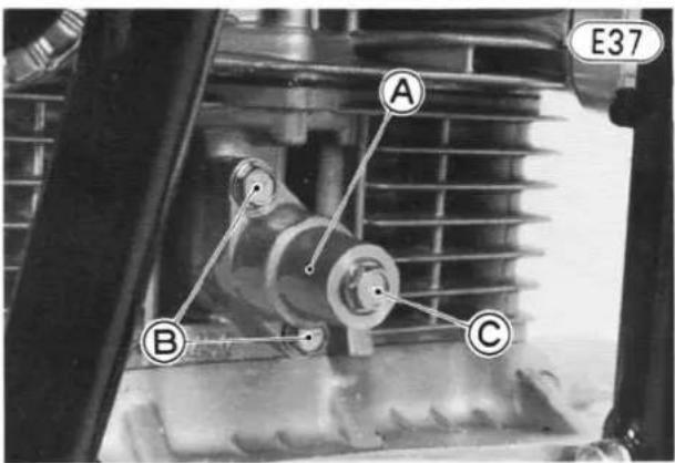
A. Tensioner
B. Mounting Bolts
C. Lock Bolt
CAUTION
-
When removing the chain tensioner, do not take out the mounting bolts by. Retightening the mounting bolts from a could damage the chain tensioner and left chain. Once the bolts are loosened, let must be removed and reset as described
-
Do not turn over the crankshaft while the camshaft chain tensioner is removed. This could upset the camshaft chain timing, and damage the engine.
●Take the long spring ⑧, flat washer ⑦, balls and retainer ⑤, short spring ②, and push rod ① and circlip ⑥ out of the cylinder block.
Camshaft Chain Tensioner
E38

-
Push Rod
-
Circlip
-
Short Spring
-
Flat Washer
-
O Ring
-
Long Spring
-
Tensioner Body
-
Lock Bolt
-
Balls and Retainer
Installation:
●Clean all parts of the tensioner using a high flash-point solvent, and apply clean engine oil to the parts.
CAUTION
The dirt or grime on the push rod can cause the tensioner malfunctioning.
●Back out the lock bolt several turns.
- Put the flat washer and long spring on the push rod end that has two parallel flat surfaces.

A. Circlip
C. Flat Surface
B. Flat Washer
D. Long Spring
●Compressing the spring, push the push rod into the tensioner body until the rod flattened end engages with the recess at the bottom of the tensioner body.
●Holding the push rod in this position, turn in the lock bolt through the tensioner body into the rod to keep the rod in place.
CAUTION
Do not use any bolt longer than 14 mm. A bolt longer than 14 mm could damage
the camshaft
hain.
WARNING
Never loosen the lock bolt before installing the tensioner on the cylinder block.
Loosening the lock bolt may cause injury by jumping the push rod out of the tensioner body.
Push Rod Locking
E40

- Push Rod
- Tensioner Body
- Circlip
- Washer
- Flat Washer
- Lock Bolt
-
Long Spring
-
Put the balls and retainer, and small spring on the push rod in this sequence, and fit the O ring into the groove.
• Install the tensioner on the cylinder block, and tighten the mounting bolts. - Loosen the lock bolt several turns until it releases the push rod.
●Tighten the lock bolt to 1.0 kg-m (87 in-lbs) of torque.
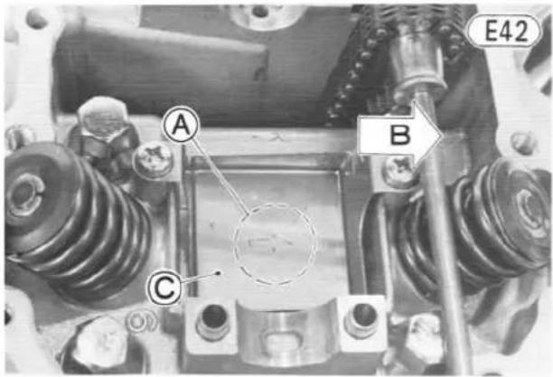
A. Arrow
B. Front
C. Oil Receiver
CAMSHAFT, CAMSHAFT SPROCKET Removal:
- Remove the fuel tank (Pg. 50).
- Remove the ignition coil (Pg. 52).
- Remove the cylinder head cover (Pg. 57).
- Remove the camshaft chain tensioner (Pg. 58).
- With a 17 mm wrench on the crankshaft to keep the shaft from turning, remove the camshaft sprocket bolts (2).
- Slide the sprocket off its position on the camshaft, and slip the chain off the sprocket.
CAUTION
Always pull the camshaft chain taut while turning the crankshaft when the camshaft chain is loose. This avoids kinking the chain on the lower (crankshaft) sprocket. A kinked chain could damage both the chain and the sprocket.
- Remove the camshaft cap bolts (6), and take off the camshaft caps.
- Remove the camshaft and camshaft sprocket. Use a screwdriver or wire to keep the chain from falling down into the cylinder block.
Installation:
- Using compressed air, blow out any particles which may obstruct the camshaft oil passages.
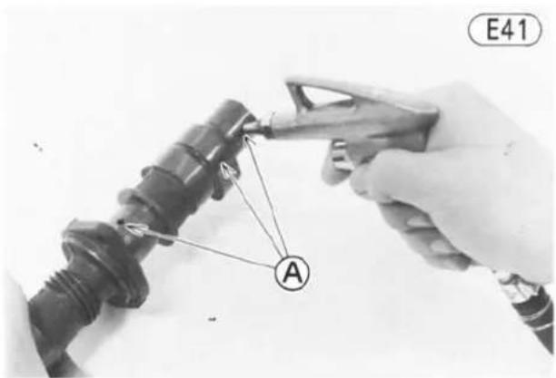
A. Oil Passages
- If the oil receiver is removed, install it so that the arrow on the sump points towards the front. Apply a non-permanent locking agent to the screws.
- Apply clean engine oil to the cam parts, camshaft caps, and cylinder head journals. When possible, apply a thin coat of a high temperature grease on the cam parts, camshaft caps, and cylinder head journals, if the camshaft, camshaft caps, and/or cylinder head are replaced with new ones.
- Run the camshaft through the camshaft chain from the right side of the engine, and remove the screwdriver or wire. The notched end of the camshaft must be on the right side of the engine.

A. Notch
- Set the camshaft sprocket on the camshaft so that the side of the camshaft sprocket marked with a timing mark (arrow mark) faces the right side of the engine.

A. Timing Mark (arrow mark)
- Check to see that the crankshaft is still at TDC (Fig. E 33), and readjust if necessary. Remember to pull the camshaft chain taut before rotating the crankshaft.
- Fit the camshaft chain onto the camshaft sprocket so that the timing mark on the sprocket is pointing to the front aligned with the cylinder head surface.

A. Timing Mark (arrow mark)
B. Front
Camshaft Chain Timing
E46
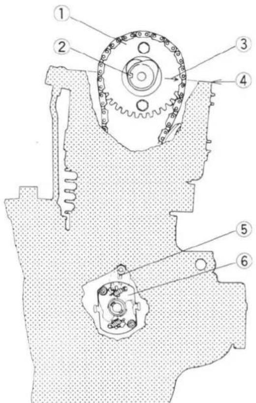
- Camshaft Sprocket
- Cylinder Head Surface
- Notch
- Timing mark
- Timing Mark (arrow mark)
- Timing Advancer
●Fit the sprocket up into place. Turn the camshaft until the notch on the right end of the camshaft faces rearward, while holding the sprocket steady to align the bolt holes.
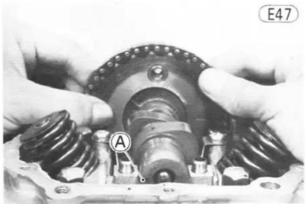
A. Face the notch rearward.
- Apply a non-permanent locking agent to the camshaft sprocket bolts.
- Keep the crankshaft from turning by holding a wrench on the crankshaft. Tighten the sprocket bolts to 1.5 kg·m (11.0 ft·lbs) of torque.
- Check that the camshaft cap knock pins (6) are fitted.
●Install the camshaft caps (3), and tighten the camshaft cap bolts to 1.2 kg·m (104 in-lbs) of torque, following the tightening sequence as shown. The arrow on each cap points forward.

A. Camshaft Cap
B. Arrow
C. Front
Camshaft Cap Tightening Order
E49
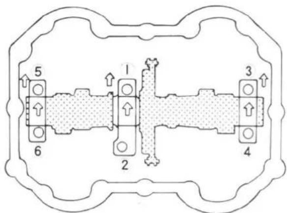
62 DISASSEMBLY-ENGINE INSTALLED
●Install the camshaft chain tensioner (Pg. 59).
- Turn the crankshaft counterclockwise until the timing mark on the camshaft sprocket is pointing forward, and recheck the camshaft timing. If the two timing mark pairs are aligned (Fig. E46), the camshaft timing is correct.
CAUTION sprocket.
Do not to try to turn the crankshaft and camshaft with a wrench on the camshaft
●Install the cylinder head cover (Pg. 58).
●Install the ignition coil (Pg. 52).
- Adjust the valve clearance (Pg. 20).
●Install the fuel tank (Pg. 50).
CYLINDER HEAD
Removal:
- Remove the fuel tank (Pg. 50).
- Remove the ignition coil (Pg. 52).
- Remove the carburetors as explained in the carburetor removal section (Pg. 52). The throttle cable need not be removed from the carburetors.
- Cover the carburetors with a clean cloth, and set them on the workbench to avoid damaging the throttle cable and carburetors.
- Remove the muffler (Pg. 56).
- Remove the cylinder head cover (Pg. 57).
- Remove the camshaft chain tensioner and O ring (Pg. 58).
- Remove the camshaft and camshaft sprocket (Pg. 60).
- Remove the oil pipe (Pg. 68).
●Stull a piece of clean cloth into the cylinder head hole for the camshaft chain, so that no parts will fall into the cylinder block.
- Remove the cylinder head nuts and copper washers (8 ea).
- With a large screwdriver, pry at the gap in each side of the cylinder head to free the cylinder head from the cylinder block.
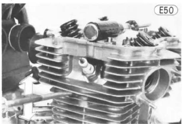
- Remove both the side reflectors.
- Take off the cylinder head and gasket. Use a screw-driver or wire to keep the chain from falling down into the cylinder block.
Installation:
- Using compressed air, blow out any particles which may obstruct the oil passages.

A. Oil Passages
- Check to see that the knock pins (2) are in place.
- Install a new cylinder head gasket with the projected corner in its opening for the chain towards the rear left side.

A. Front B. Projection
●Install the cylinder head. Lift up the camshaft chain, and use a screwdriver or wire to keep the chain from falling down into the cylinder block.
- Stuff a piece of clean cloth into the cylinder head hole for the camshaft chain, so that no parts will fall into the cylinder block.
● Tighten the cylinder head nuts (8) first to about 2.0 kg·m (14.5 ft·lbs) of torque and then to 4.0 kg·m (29 ft·lbs) of torque, following the tightening sequence numbers on the cylinder head. Each nut has a copper washer.
Cylinder Head Nut Tightening Order E53

●Install the oil pipe (Pg. 68).
- Remove the cloth from the cylinder head.
●Install the camshaft and camshaft sprocket (Pg. 60).
• Install the camshaft chain tensioner and O ring (Pg. 59).
●Install the cylinder head cover (Pg. 58).
●Install the ignition coil (Pg. 53).
●Install the carburetors (Pg. 53).
●Install the muffler (Pg. 57).
●Install the fuel tank (Pg. 50).
- Adjust the valve clearance (Pg. 20).
- Check the throttle cable, and adjust if necessary (Pg. 21).
- Check the carburetors, and adjust if necessary (Pg. 22).
- Remove the tool, and then remove the spring retainer 2, outer spring 3, and inner spring 5.
●Push out the valve 10 or 11 - Remove the clip 7 and pull off the oil seal 8.
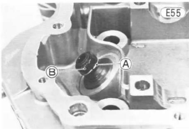
A. Clip
B. Oil Seal
- Remove the inner spring seat 6 and outer spring seat 4.
- Heat the area around the guide to about 120\~150°C (248\~302°F), and hammer lightly on the valve guide arbor (special tool) to remove the guide from the top of the cylinder head.
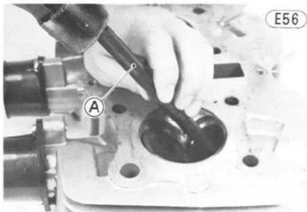
A. Valve Guide Arbor (57001-163)
VALVE, VALVE GUIDE
Removal (each valve and valve guide):
- Remove the cylinder head (Pg. 62).
- Remove the spark plugs (2) from the cylinder head.
- Using the valve spring compressor assembly (special tool) to press down the valve spring retainer 2, remove the split keeper 1.
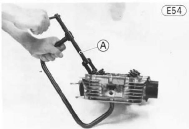
A. Valve Spring Compressor Assembly (57001-241)
Installation (each valve and valve guide):
NOTE: If a new valve or valve guide is installed, check the valve/valve guide clearance (Pg. 160).
- Apply oil to the valve guide.
- Heat the area around the valve guide hole to about 120 150° C ( 248 302° F ), and drive the valve guide in from the top of the head using the valve guide arbor (special tool).
- Ream the valve guide with the valve guide reamer (special tool) even if the old guide is reused.

A. Valve Guide Reamer (57001-162)
●Lap the valve to check that it is seating properly. If it is uneven, refer to the Maintenance Section (Pg. 159).
●Push a new oil seal into place, and install its clip.
- Apply a thin coat of high temperature grease to the valve stem, insert the valve, and install the outer and inner spring seats and the outer and inner springs with the concentrated portion of each spring down as shown.

A. Concentrated Portion
E59
Valve and Valve Guide

- Split Keeper
- Spring Retainer
- Outer Spring
- Outer Spring Seat
- Inner Spring
- Inner Spring Seat
- Clip
- Oil Seal
- Valve Guide
- Exhaust Valve
- Inlet Valve
- Cylinder Head
●Install the spring retainer, press it down with the valve spring compressor assembly (special tool), and put on the split keeper.
●After making sure that the split keeper, spring retainer, and valve stem are all properly fitted, remove the valve spring compressor assembly.
●Install the cylinder head (Pg. 62).
CYLINDER BLOCK
Removal:
- Remove the cylinder head (Pg. 62).
- Remove the cylinder head knock pins (2).
- With a wide screwdriver, pry at the gap in the cylinder base to free the cylinder block from the crankcase.
CAUTION
Do not hammer on the screwdriver while it is in the pry point as engine damage
could result.
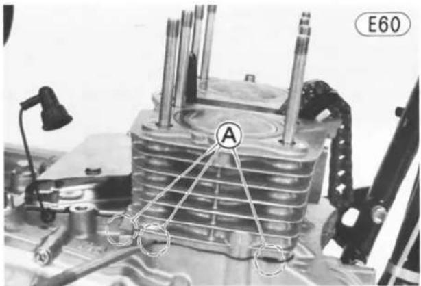
A. Pry Points
- Remove the cylinder block and gasket.
- Wrap a clean cloth around the base of each piston so that no parts or dirt will fall into the crankcase.
Installation:
NOTE: If the cylinder block is replaced with a new one, piston to cylinder clearance must be checked against the specified value (Pg. 165).
- Remove the cloth from under each piston.
- Check to see that the knock pins (2) and rear camshaft chain guide are in place.


A. Knock Pins
B. Rear Camshaft Chain Guide
●Install a new cylinder base gasket.
- Lifting up the camshaft chain so it doesn't get caught, turn the crankshaft so that the crankshaft is at TDC, and slip the piston bases (special tools) under the pistons to hold them level.
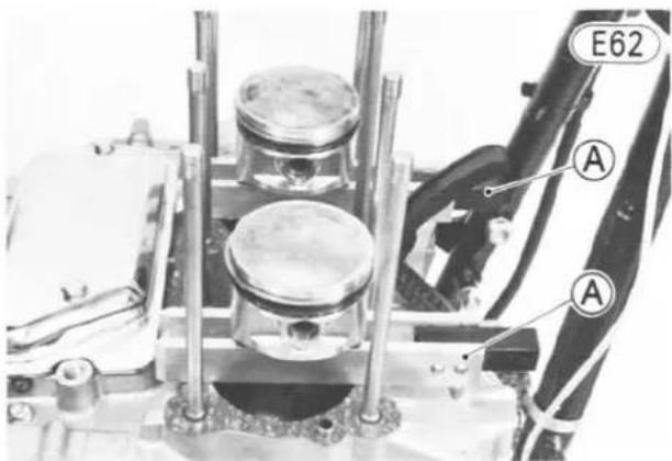
A. Piston Base (57001-341)
- Position each piston ring so that the opening in the top and the oil ring expander of each piston is facing forward, and the second ring opening faces the rear. The openings of the oil ring steel rails must be positioned so that one is about 30° on one side of the opening of the expander, and the other about 30° on the other side of the expander opening.
Piston Ring Opening (front side view)
E63

- Apply a clean engine oil to the piston rings and cylinder inside surfaces. When possible, apply a thin coat of a high temperature grease on the pistons and cylinder inside surfaces, if the pistons and/or cylinder block are replaced with new ones.
- Compress the piston rings using a piston ring compressor assembly (special tool).

A. Piston Ring Compressor Assembly (57001-921)
- Work the bottom of each cylinder past the rings, and set the cylinder block in place while removing the special tools.
●Fit the cylinder head knock pins (2).
●Install the cylinder head (Pg. 62).
CAMSHAFT CHAIN GUIDE (REAR)
Removal:
- Remove the cylinder block (Pg. 65).
- Pushing the rear camshift chain guide up, remove the upper guide pin, and remove the guide and lower guide pin.

A. Camshaft Chain Guide
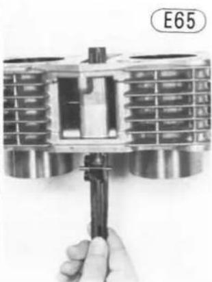
B. Upper Guide Pin
Installation Note:
- Install the rear camshaft chain guide in the cylinder block, so that the projecting side of the guide faces the left side of the engine.

A. Projection
PISTON, PISTON RINGS
Removal:
- Remove the cylinder block (Pg. 65).
- Wrap a clean cloth around the base of each piston to secure it in position for removal and so that no parts and dirt will fall into the crankcase.
- Remove the piston pin snap ring from the outside of each piston.
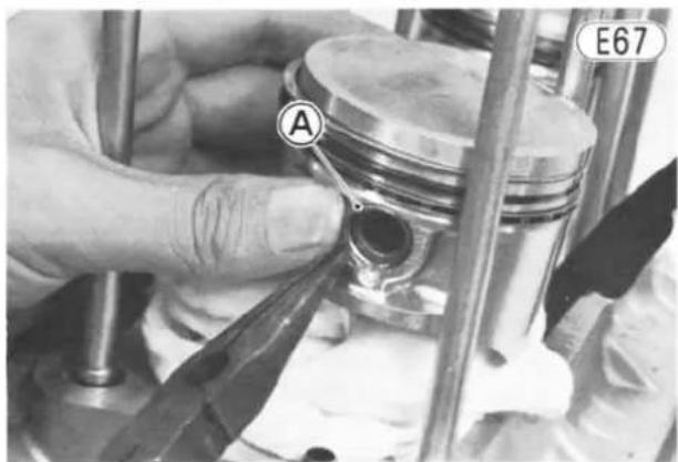
A. Snap Ring
- Remove each piston by pushing its piston pin out the side that the snap ring was removed. Use the piston pin puller and adapter "B" (special tools) if necessary.

A. Piston Pin Puller (57001-910)
B. Adapter "B" (57001-913)
- Remove the top and second rings with the piston ring pliers (special tool). To remove a ring by hand, spread the ring opening with both thumbs, and then push up on the opposite side.
- Remove the upper and lower oil ring steel rails, and then remove the oil ring expander.

A. Piston Ring Pliers (57001-115)

Installation:
NOTE: If the piston is replaced with a new one, check that piston to cylinder clearance has the specified value (Pg. 165). Also, when a new piston or piston pin is installed, check that the piston to pin clearance has the specified value (Pg. 167).
- To install the oil ring, first install the expander so that the expander ends butt together, and then install the upper and lower steel rails. The two steel rails are identical. There is no "up" or "down" to the rails; they can be installed either way.
Oil Ring Expander Installation
E71

- Install the top and second rings so that the correct side (marked "N") faces up. The cross section of the top ring is rectangle, and the cross section of second ring is tapered.
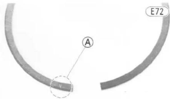
A. "N" Mark
Top Ring, Second Ring
E73
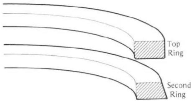
- Turn the rings so that the opening in the top ring and oil ring of each piston faces forward and the opening in the second ring faces the rear. The openings of the oil ring steel rails must be slipped to both directions about 30° from the opening of the expander (Fig. E63).
- Apply a little engine oil to the piston pins, and install the pistons and piston pins. The arrow on the top of each piston must point towards the front.
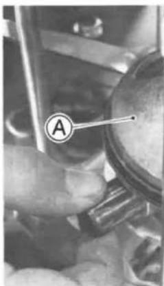
A. Piston
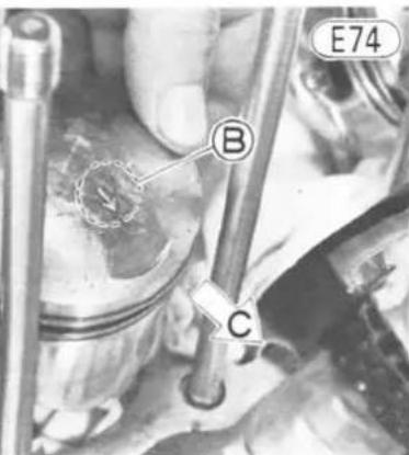
B. Arrow Mark
C. Front
DISASSEMBLY-ENGINE INSTALLED
- Fit a new piston pin snap ring into the side of each piston, taking care to compress it only enough to install it and no more. Check that the other snap ring is in place.

Do not reuse snap rings, as removal weakens and deforms the snap ring. It could
fall out and score the cylinder wall.
●Install the cylinder block (Pg. 65).
OIL PIPE
Removal:
- Remove the fuel tank (Pg. 50).
- Remove carburetors (Pg. 52). The throttle cable need not be removed from the carburetors.
- Cover the carburetors with a clean cloth, and set them on the workbench to avoid damaging the throttle cable and carburetors.
- Using a wrench to hold the upper end of the oil pipe, remove the banjo bolt to disconnect the oil pipe upper end from the cylinder head. The banjo bolt has two washers.
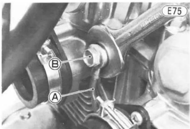
A. Oil Pipe
B. Banjo Bolt
- Disconnect the oil pressure switch lead from the switch, and remove the oil pressure switch.

A. Oil Pressure Switch
C. Long-hex-head Bolt
B. Oil Pipe
- Remove the long-hex-head bolt, and take off the oil pipe. There is a washer on each side of the pipe fitting.
Installation:
- Check the oil pipe, and replace it if it is bent or damage. CAUTION Do not use a bent or damaged oil pipe, as it may cause serious engine damage.
- With compressed air, blow out the oil passage to remove dirt or particles which may obstruct oil flow.
- Install the oil pipe with the long-hex-head bolt and banjo bolt finger tight. Each bolt has two washers, one on each side of the fitting. Discard the old washers, and use new washers.
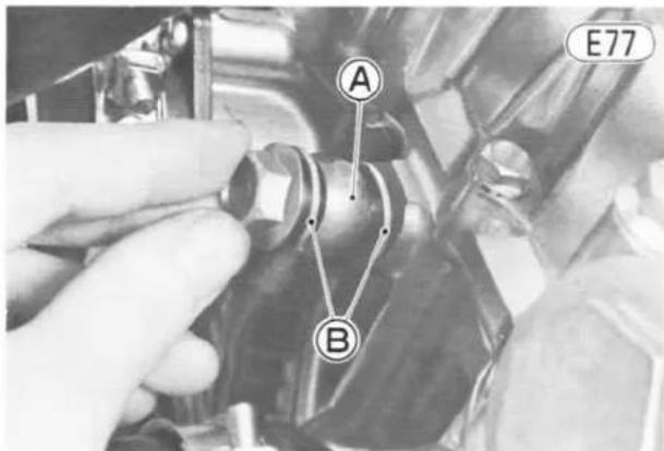
A. Fitting
B. New Washers
- Using a wrench to hold the end of the oil pipe, tighten the long-hex-head and oil pipe banjo bolt to 2.0 kg-m (14.5 ft-lbs) of torque.
●Install the oil pressure switch tightening it to 1.5 kg-m (11.0 ft-lbs) of torque. - Connect the oil pressure switch lead to the switch.
●Install the carburetors (Pg. 53).
●Install the fuel tank (Pg. 50). - Check the throttle cable (Pg. 21), and adjust if necessary.
OIL PRESSURE SWITCH
Removal:
●Pull the oil pressure switch lead off the switch.

A. Switch Lead
B. Oil Pressure Switch
- Remove the oil pressure switch.
Installation Note:
● Tighten the oil pressure switch to 1.5 kg-m (11.0 in-lbs) of torque.
ENGINE SPROCKET (or PULLEY) COVER
Removal:
- Remove the left footpeg bolt, lockwasher, and left footpeg (Fig. E79).

A. Footpeg
B. Shift Pedal
- Remove the shift pedal bolt, and take off the shift pedal.
- For the models that have the automatic side stand return mechanism, remove the pivot bolt of the side stand drive lever, and slide the rod towards the rear. There is a lockwasher, flat washer, and collar.

A. Pivot Bolt
C. Rod
B. Lever
D. Engine Sprocket (or Pulley) Cover
- Remove the engine sprocket (or pulley) cover screws (4), and pull the cover free from the crankcase.
- Remove the cotter pin from the clutch release lever, and free the clutch inner cable tip from the lever and engine sprocket (or pulley) cover.
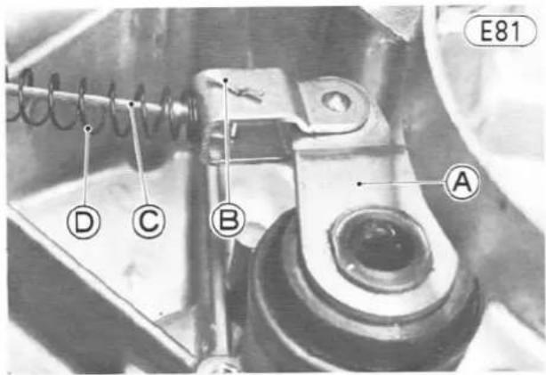
A. Release Lever
C. Inner Cable
B. Cotter Pin
D. Spring
Installation:
- Run the clutch cable into the engine sprocket (or pulley) cover and spring, and fit the tip of the inner cable into the clutch release lever.
- Using a new cotter pin, secure the cable tip to the release lever.
- Check that the engine sprocket (or pulley) cover knock pins (2) and clutch push rod are in place, and install the engine sprocket (or pulley) cover using the shift shaft oil seal guide (special tool) to protect the oil seal in the cover.

A. Shift Shaft Oil Seal Guide (57001-264)
●Tighten the engine sprocket (or pulley) cover screws (4).
• Install the left footpeg and lockwasher, and tighten the left footpeg bolt.
- For the models that have the automatic side stand return mechanism, install the side stand drive lever hooking the rod on the lever. The pivot bolt has a collar, flat washer, and lockwasher.
70 DISASSEMBLY-ENGINE INSTALLED
- Mount the shift pedal so that its end matches the level of the left footpeg, and tighten its bolt.
- Check the clutch, and adjust if necessary (Pg. 25).
- Check the automatic side stand return mechanism (where provided), and adjust if necessary (Pg. 38).
CLUTCH RELEASE
Removal:
- Remove the engine sprocket (or pulley) cover (Pg. 69).
- For the chain driven motorcycle, remove the drive chain guard screws (4), and take off the guard.
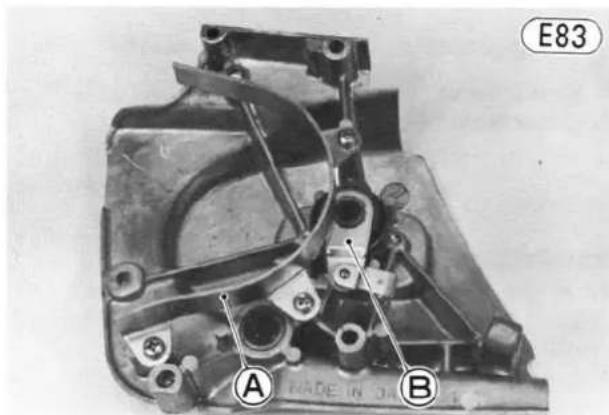
A. Drive Chain Guard
B. Clutch Release Lever
- Remove the clutch release lever and steel ball assembly.
- Remove the clutch adjusting cover screws (2), and take off the cover.
- Remove the clutch adjusting screw locknut, adjusting screw, and ball ramp plate.
Installation:
- Wash and clean the clutch release lever, steel ball assembly, and ball ramp plate with a high flash-point solvent. Dry and lubricate them with grease.
- Install the adjusting screw and ball ramp plate, aligning the ridge on the engine sprocket (or pulley) cover with the groove in the ball ramp plate.

A. Fit the ridge and the groove.
B. Ramp Plate
●Install the adjusting screw locknut with finger tight.
●Install the steel ball assembly.
- Apply a grease to the grease seal, and install the clutch release lever.
- For the chain driven motorcycle, install the drive chain guard, and tighten its screws (4), applying a non-permanent locking agnet to the screws.
●Install the engine sprocket (or pulley) cover (Pg. 69), and adjust the clutch (Pg. 25).
- Check the automatic side stand return mechanism (where provided), and adjust if necessary (Pg. 38).
NEUTRAL SWITCH
Removal:
- Remove the engine sprocket (or pulley) cover (Pg. 69). The clutch cable need not be removed from the clutch release.
●Pull the neutral switch lead off the switch.

A. Switch Lead
B. Neutral Switch
●Unscrew the neutral switch and gasket.
Installation:
●Install the neutral switch and gasket tightening it 1.5 kg-m (11.0 ft-lbs) of torque.
●Fit the lead back on the switch.
•Install the engine sprocket (or pulley) cover (Pg. 69).
-Adjust the clutch (Pg. 25).
- Check the automatic side stand return mechanism (where provided), and adjust if necessary (Pg. 38).
ENGINE SPROCKET (or PULLEY)
Removal:
- Remove the engine sprocket (or pulley) cover (Pg. 69). The clutch cable need not be removed from the clutch release lever.
-
For chain driven models, remove the drive chain (Pg. 117).
-
For the belt driven model, pull out the clutch push rod, and fully move the rear wheel forward so that the belt is too loose.
- For the models that have the automatic side stand return mechanism, remove the pivot bolt of the lever, and take off the lever, rod, and lever spring. The pivot bolt has a nut, collar, lockwasher, and flat washer.
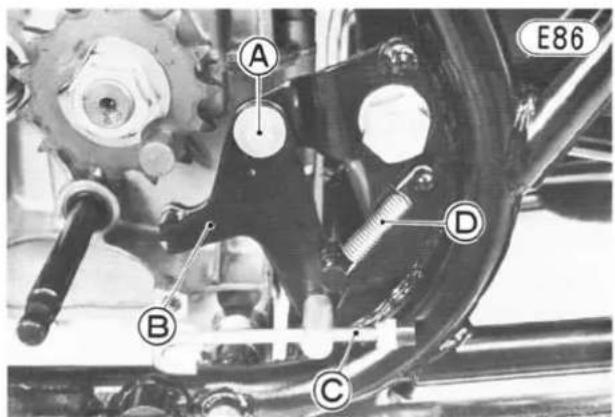
A. Pivot Bolt
C. Rod
B. Lever
D. Lever Spring
●Straighten the side of the splined washer that is bent over the side of the engine sprocket (or pulley) nut.

A. Splined Washer
- Hold the engine sprocket (or pulley) steady using the holder (special tool), and remove the nut, splined washer, and engine sprocket (or pulley).

A. Engine Sprocket Holder (57001-307)

A. Holder (57001-1037)
Installation:
- Mount the engine sprocket (or pulley), and install the splined washer on the output shaft fitting their splines.
- Install the engine sprocket (or pulley) nut, and then tighten the nut to 8.5 kg-m (61 ft-lbs) of torque while using the holder to hold the sprocket (or pulley) steady.
●Bend one side of the splined washer over the side of the nut. - Install the lever, rod, and lever spring as shown in Fig. E86. The pivot bolt has a flat washer, lockwasher, collar, and nut.
- For chain driven models, install the drive chain (Pg. 118).
- For the belt driven model, install the clutch push rod.
●Install the engine sprocket (or pulley) cover (Pg. 69). - Check the clutch (Pg. 25), and adjust if necessary.
- Check the drive chain or belt (Pg. 30 or 31), and adjust if necessary.
- Check the automatic side stand return mechanism (where provided), and adjust if necessary (Pg. 38).
ALTERNATOR STATOR
Removal:
- Remove the engine sprocket (or pulley) cover (Pg. 69). The clutch cable need not be removed from the clutch release.
●Disconnect the alternator yellow leads (2).
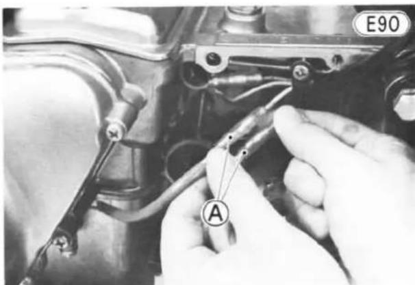
A. Alternator Stator Yellow Leads
72 DISASSEMBLY-ENGINE INSTALLED
●Place an oil pan beneath the alternator cover.
- Remove the alternator cover screws (9), and pull off the alternator cover and gasket.
- Remove the starter motor chain guide screws (2), and take off the chain guide and lead holding plate.

A. Starter Motor Chain Guide
B. Lead Holding Plate
- Remove the stator Allen bolts (3) ⑪, and pull the stator ① and the grommet ② out of the cover.
Installation:
●Install the grommet, and set the alternator stator into place. Apply a non-permanent locking agent on each Allen bolt, and tighten the bolts to 1.0 kg-m (87 in-lbs) of torque.
- Install the lead holding plate and starter motor chain guide. Apply a non-permanent locking agent on each chain guide screw, and tighten the screws (2).
- Check that the knock pins (2) are in place, install the alternator cover using a new gasket, and tighten its screws (9). Before installing the cover gasket, apply a liquid gasket to the portions on it where they contact the crankcase mating surface.
- Connect the alternator yellow leads (2).
•Install the engine sprocket (or pulley) cover (Pg. 69).
- Check the clutch (Pg. 25), and adjust if necessary.
- Check the oil level (Pg. 26), and add more if necessary.
- Check the automatic side stand return mechanism (where provided), and adjust if necessary (Pg. 38).
ALTERNATOR ROTOR, STARTER MOTOR CLUTCH
Removal:
- Remove the engine sprocket (or pulley) cover (Pg. 69). The clutch cable need not be removed from the clutch release.
●Disconnect the alternator yellow leads (2). - Place an oil pan beneath the alternator cover.
- Remove the alternator cover screws (9), and pull off the alternator cover and gasket.
- Hold the alternator rotor 3 steady with the holder (special tool), and remove the bolt 12. The bolt is a
left hand thread and must be turned clockwise for removal.
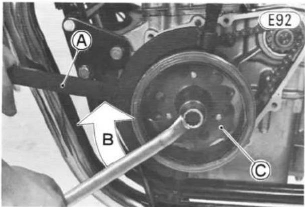
A. Holder (57001-308) B. Turn clockwise.
C. Alternator Rotor
- Using the special tool to hold the rotor steady, remove the rotor and starter motor clutch assembly with the rotor puller (special tool). There is a thrust washer at the rear of the rotor.
CAUTION If the rotor is difficult to remove and a hammer is used, turn the bar with hand tapping the head of the puller shaft with a hammer. Do not attempt to strike the bar or the alternator rotor itself. Striking the bar or the rotor can cause the bending or the magnets to lose their magnetism.

A. Rotor Puller (57001-254)
Installation:
- Using a high flash-point solvent, clean off any oil or dirt that may be on the crankshaft taper or alternator rotor hub.
- Check to see that the thrust washer is at the rear of the rotor, and place the rotor and starter motor clutch assembly back on the crankshaft.
● Tighten the bolt to 7.0 kg-m (51 ft-lbs) of torque while holding the rotor steady with the holder (special tool). - Check that the knock pins (2) are in place, install the alternator cover using a new gasket, and tighten its screws (9). Before installing the cover gasket, apply a liquid gasket to the portions on its where they contact the crankcase mating surface.
- Connect the alternator yellow leads (2).
●Install the engine sprocket (or pulley) cover (Pg. 69).
- Check the clutch (Pg. 25), and adjust if necessary.
- Check the oil level (Pg. 26), and add more if necessary.
- Check the automatic side stand return mechanism (where provided), and adjust if necessary (Pg. 38).
Disassembly:
- Remove the rollers ⑥, springs ④, and spring caps ⑤ (3 ea) from the starter motor clutch.

A. Starter Motor Clutch
B. Roller
C. Spring Cap
D. Spring
- Place the alternator rotor face down on the workbench. Holding the rotor steady with the holder (special tool), remove the Allen bolts (3) to separate the rotor and starter motor clutch (Fig. E95).
Alternator, Starter Motor Clutch

A. Holder (57001-308)
Assembly Note:
- Apply non-permanent locking agent to the starter motor clutch Allen bolts (3), and tighten the bolts to 3.5 kg-m (25 ft-lbs) of torque.
STARTER MOTOR CHAIN, SPROCKETS Removal:
- Remove the engine sprocket (or pulley) cover (Pg. 69). The clutch cable need not be removed from the clutch release.
- Remove the alternator rotor and starter motor clutch assembly (Pg. 72).
●Pull off the starter motor chain 10 and sprockets 9, 14.
E96

- Alternator Stator
- Grommet
- Alternator Rotor
- Spring
- Spring Cap
- Roller
-
Starter Motor Clutch
-
Allen Bolt
- Starter Motor Sprocket
- Starter Chain
- Allen Bolt
- Rotor Bolt
- Washer
- Starter Motor Sprocket
74 DISASSEMBLY-ENGINE INSTALLED
Installation Notes:
- Install the thrust washer before installing the alternator rotor and starter motor clutch assembly.
- After installing the starter motor chain and sprockets, check the oil level (Pg. 26), and add more if necessary.
- Check the automatic side stand return mechanism (where provided), and adjust if necessary.
STARTER MOTOR
Removal:
- Remove the fuel tank (Pg. 50).
- Remove the carburetors (Pg. 52).
- Remove the engine sprocket (or pulley) cover (Pg. 69). The clutch cable need not be removed from the clutch release lever.
●Disconnect the alternator yellow leads (2).

A. Alternator Yellow Leads
B. Alternator Cover
- Place an oil pan beneath the alternator cover.
- Remove the alternator cover screws (9), and pull off the alternator cover and gasket.
- Remove the starter motor cover bolts and flat washers (2 ea), and take off the cover and gasket.

A. Starter Motor Cover
B. Rubber Cap
- Slide off the rubber cap, remove the starter motor terminal nut and lockwasher, and free the lead from the motor.
- Using a T wrench with a pivoted socket, remove the starter motor retaining bolts (2).
●Pry the starter motor loose from the crankcase with a screwdriver, slide the starter motor off towards the right side of the engine, and then lift it upwards.
CAUTION
Do not tap on the starter motor shaft. Tapping on the shaft may damage the

A. Starter Motor
Installation:
- Replace the O ring with a new one, if it is deteriorated or damaged, and apply a little oil to it.
- Clean the starter motor lugs and crankcase where the starter motor is grounded.


A. Starter Lugs
B. Lug Mating Surfaces
- Place the starter motor back in position, fitting the shaft through the sprocket with the chain in place.
- Connect the starter motor lead to the terminal with its lockwasher and nut, and tighten the nut.
- Slide back the rubber cap.
- Apply a non-permanent locking agent to the starter motor retaining bolts, and tighten the bolts to 1.0 kg-m (87 in-lbs) of torque.
-
Check that the oil pressure switch lead grommet is in place.
●Install the starter motor cover and gasket, and tighten its bolts. Each bolt has a flat washer. -
Check that the knock pins (2) are in place, install the alternator cover using a new gasket, and tighten its screws (9). Before installing the cover gasket, apply a liquid gasket to the portions on it where they contact the crankcase mating surface.
- Connect the alternator yellow leads (2).
●Install the engine sprocket (or pulley) cover (Pg. 69).
●Install the carburetors (Pg. 53).
●Install the fuel tank (Pg. 50). - Check the clutch (Pg. 25), and adjust if necessary.
- Check the throttle cable (Pg. 21), and adjust if necessary.
- Check the oil level (Pg. 26), and add more if necessary.
- Check the automatic side stand return mechanism (where provided), and adjust if necessary.
Disassembly:
- Remove the screws 23 (2) and lockwashers 19 (2), and then remove the end covers 1, 18. There is an O ring 2, 25 at the each side of the yoke assembly.
- Remove the planet pinions 12 (2), internal gear 14, key 24, end plate 11, thrust washers 10, armature 9 and thrust washers 8.
- Remove the nut 6, lockwasher, flat washer, large and small gasket, and remove the terminal with the brush assembly 5.
NOTE: The yoke assembly 7 is not meant to be disassembled.
Starter Motor
E101


- End Cover
- O Ring
- Brush
- Brush Assembly
- Brush Lead
- Nut
-
Yoke Assembly
-
Thrust Washers
- Armature
- Thrust Washers
- End Plate
- Planet Pinion
- Output Shaft
-
Internal Gear
-
O Ring
- Grease Seal
- Thrust Washers
- End Cover
- Lockwasher
- Thrust Washers
-
Circlip
-
Sprocket
- Screw
- Key
- O Ring
76 DISASSEMBLY-ENGINE INSTALLED
Assembly Notes:
- Replace any O rings that are deteriorated or damaged with new ones.
- Apply a high temperature grease to the planet pinions, internal gear, and planet pinion shafts on the output shaft.
- Align the tongue on the yoke assembly with the notch on the end plate, and align the notch in the internal gear ⑭ with the tongue on the yoke assembly. Align the key on the end cover ⑱ with the notch in the internal gear.
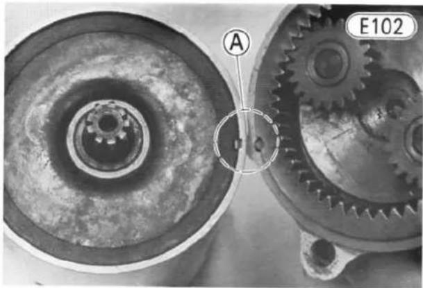
A. Align the tongue with the notch.
4. Align the tongue on the brush assembly ④ with the notch on the yoke assembly, and align the tongue on the brush assembly ④ with the notch on the end cover ①.
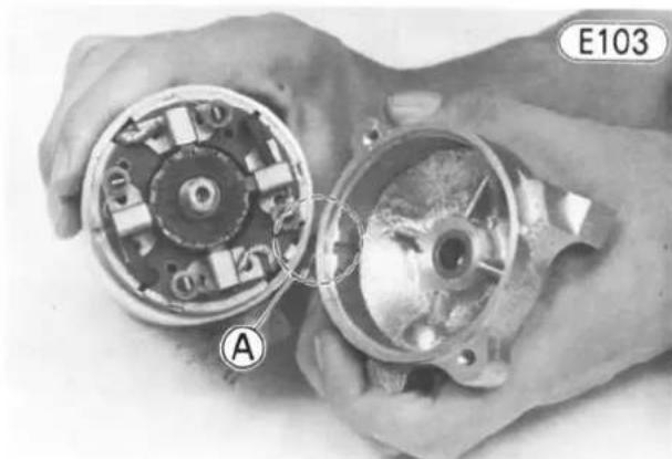
A. Align the tongue with the notch.
5. Tighten the nut ⑥ to 1.1 kg-m (8.0 ft-lbs) of torque.
CONTACT BREAKER
Removal:
- Remove the contact breaker cover screws (2), and take off the cover and gasket.
- Remove the contact breaker base screws (2). Each screw has a flat washer and lockwasher.

A. Base Screws
B. Terminal Nut
C. Contact Breaker
- Loosen the contact breaker terminal nut, and free the contact breaker from the engine by pulling off the contact breaker and capacitor leads at the same time.
Installation Notes:
- The sequence of installation on the contact breaker terminal bolt is: bolt 11, flat washer 10, contact breaker lead 9, capacitor lead 12, spring 7, large insulator 13, small insulator 14 (in contact breaker hole), large insulator 16, flat washer 17, lockwasher 18, and nut 19.
Contact Breaker Lead Installation
E105
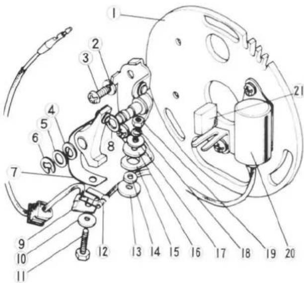
- Contact Breaker Mounting Plate
- Lockwasher
- Screw
- Washer
- Washer
- C Ring
- Spring
- Washer
- Contact Breaker Lead
-
Flat Washer
-
Bolt
- Capacitor Lead
- Large Insulator
- Small Insulator
- Contact Breaker Base
- Large Insulator
- Flat Washer
- Lockwasher
- Nut
- Capacitor
-
Felt
-
When installing the contact breaker, fit the contact breaker base pin into the hole on the starter plate.
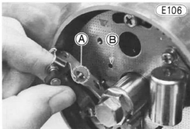
A. Pin
B. Hole
- After installation, adjust the ignition timing (Pg. 18).
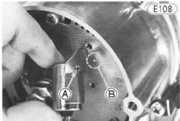
A. Hole
B. Pin
CAPACITOR
Removal:
- Remove the contact breaker cover screws (2), and take off the cover and gasket.
- Remove the capacitor mounting screw and lockwasher.

A. Mounting Screw
C. Terminal Nut
B. Capacitor
- Loosen the contact breaker terminal nut, and remove the capacitor lead to complete capacitor removal.
Installation Notes:
- The sequence of installation on the contact breaker bolt is: bolt, flat washer, contact breaker lead, capacitor lead, spring, large insulator, small insulator (in contact breaker hole), large insulator, flat washer, lockwasher, and nut (Fig. E105).
- Match the capacitor mounting plate hole with the pin on the stator plate.
TIMING ADVANCER
Removal:
- Remove the contact breaker cover screws (2), and take off the cover and gasket.
- Remove the mounting plate screws (3), and take off the mounting plate.

A. Screws
B. Mounting Plate
- With a 17 mm wrench on the crankshaft rotation nut to keep the shaft from turning, remove the advancer mounting bolt, and take off the rotation nut and the timing advancer.
Installation Notes:
- Fit the timing advancer onto the crankshaft, matching its notch with the pin in the end of the crankshaft, and install the crankshaft rotation nut and the advancer mounting bolt. The notches in the nut fit the projections on the timing advancer. Tighten the bolt to 2.5 kg·m (18.0 ft·lbs) of torque.
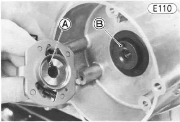
A. Notch
B. Pin
- After installing the timing advancer, adjust the ignition timing (Pg. 18).
Disassembly:
●Turn the cam counterclockwise and pull off the cam.

A. Cam
- Remove the C rings (2), washers (4), and weights (2).
- Remove the washers (2) from the advancer body.
Assembly Notes:
- Wipe the advancer clean, and fill the groove inside the cam with grease (Pg. 223).
- When installing the cam, align the mark on the cam with the hole on the advancer body.

A. Mark
B. Hole
PRIMARY CHAIN GUIDES
Removal:
- Remove the right engine cover.
- Remove the primary chain guide screws and flat washers (2 ea), and take off the guides (2).
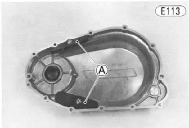
A. Primary Chain Guides
Installation Note:
- Apply a non-permanent locking agent to the guide screws, and tighten the screws.
CLUTCH, PRIMARY CHAIN, PRIMARY SPROCKET
Removal:
- Remove the timing advancer (Pg. 77).
- Remove the right engine cover.
- Remove the clutch spring bolts 18 and springs 17 (4 ea).

A. Clutch Spring Bolts
B. Spring Plate
- Pull off the spring plate 16 and spring plate pusher 15, and tilt the motorcycle so that the steel ball 14 will fall out.
- Remove the friction plates ③ (6) and steel plates ④ (5)
- Remove the circlip ⑥ and shim(s) ⑤, and pull off the clutch hub ②. There is a thrust washer ① between the clutch hub and the clutch housing ⑬.
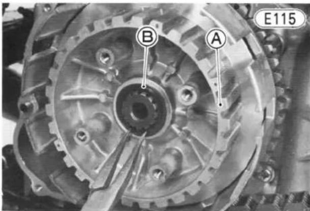
A. Clutch Hub
B. Circlip
- Remove the primary sprocket circlip ⑪.
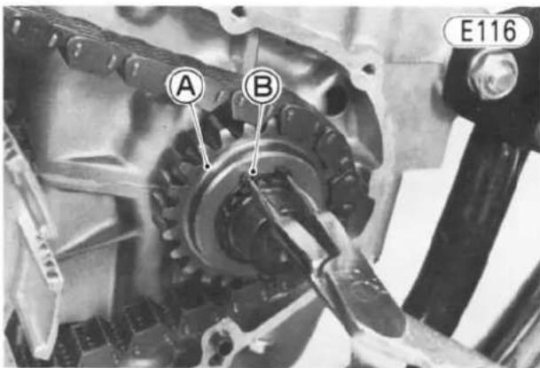
A. Primary Sprocket
B. Circlip
- Pull off the clutch housing 13, primary chain 12, and primary sprocket 10 all together.
Installation:
- Check that the oil pump drive gear is in place, and the oil pressure relief valve is in place.

A. Relief Valve
C. Oil Pump Gear
B. Pump Drive Gear
- Assemble the clutch housing, primary sprocket, and primary chain, and install them while turning the oil pump gear by hand so that the oil pump gear will mesh
with the oil pump drive gear. The protruding side of the primary sprocket must face out.
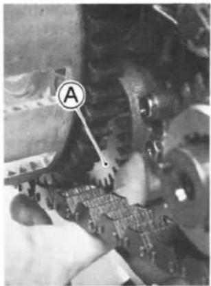
A. Oil Pump Gear

B. Protruding Side
• Install the primary sprocket circlip.
- Install the thrust washer, clutch hub, shim(s), and circlip.
- Insert a thickness gauge between the circlip and the shim, and measure the side clearance of the clutch hub. If the clearance is excessive, replace the present shim(s) with new one(s) and/or add more shim(s), which will give the proper clearance (Table E1).
NOTE: Shims are available in 0.3 and 0.5 mm sizes.

Table E1 Clutch Hub Side Clearance
| Standard |
| under 0.3 mm |
●Install the friction plates (6) and steel plates (5), starting with a friction plate and alternating them.
CAUTION If new, dry steel plates and friction plates are installed, apply engine oil on the surfaces of each plate to avoid clutch plate seizure.
- Apply a high temperature grease to the steel ball and spring plate pusher surfaces.
●Insert the steel ball and spring plate pusher.
●Fit the spring plate back into place, aligning the mark on the plate with the mark on the clutch hub.
CAUTION Misalignment of the spring plate can cause clutch drag (when it is disengaged), or clutch slipping.

- Thrust Washer 10. Primary Sprocket
- Clutch Hub 11. Circlip
- Friction Plate 12. Primary Chain
- Steel Plate 13. Clutch Housing
- Shim(s) 14. Steel Ball
- Circlip 15. Spring Plate Pusher
- Circlip 16. Spring Plate
- Pin 17. Spring
- Oil Pump Drive Gear 18. Bolt
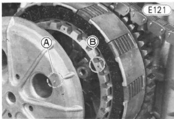
A. Raised Point Mark
B. Punch Mark
●Install the springs and spring bolts (4 ea). Cross tighten the bolts evenly to 1.0 kg-m (87 in-lbs) of torque.
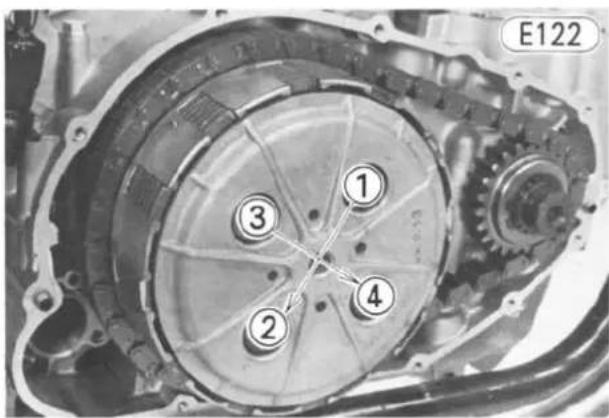
●Install the right engine cover.
●Install the timing advancer (Pg. 77).
- Adjust the clutch (Pg. 25).
- Adjust the ignition timing (Pg. 18).
- Fill the engine with oil, check the oil level (Pg. 26), and add more if necessary.
- Adjust the ignition timing (Pg. 18).
- Fill the engine with oil, check the oil level (Pg. 26), and add more if necessary.
●Install the right engine cover.
●Install the timing advancer (Pg. 77).
-Adjust the clutch (Pg. 25).
●Adjust the ignition timing (Pg. 18).
- Fill the engine with oil, check the oil level (Pg. 26), and add more if necessary.
OIL PUMP DRIVE GEAR
Removal:
- Remove the timing advancer (Pg. 77).
- Remove the right engine cover.
- Remove the clutch (Pg. 78).
- Remove the circlip ⑦, pull off the oil pump drive gear ⑨ and pin ⑧.

A. Oil Pump Drive Gear
B. Circlip
Installation:
●Install the pin into the clutch housing.
- Install the oil pump drive gear, fitting the gear groove with the pin. The protruding side of the gear faces the clutch housing.
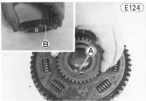
A. Pin
B. Protruding Side
●Install the circlip.
●Install the clutch (Pg. 79).
OIL PUMP
Removal:
- Remove the clutch, primary sprocket, and primary chain (Pg. 78).
- Remove the oil pump mounting screws (4) 3, and pull off the oil pump and gasket 1.

A. Mounting Screws
Installation Notes:
- Fill the oil pump with oil for initial lubrication.
- Before installing the oil pump, check to see that the knock pins (2) are in place.

A. Knock Pins
B. Gasket
- Replace the oil pump gasket with a new one.
82 DISASSEMBLY-ENGINE INSTALLED
Oil Pump
E127

- Gasket
- Cover Plate
- Mounting Screw
- Outer Rotor
- Knock Pin
- Pump Body
- Bolt
- Lockwasher
Disassembly:
- Remove the bolt ⑦ and lockwasher ⑧, and take off the cover plate ②

A. Bolt
B. Cover Plate
- Remove the outer rotor ④.
Assembly Notes:
- Check to see that the knock pins ⑤ are in place.
- After completing the oil pump assembly, check that the rotor shaft and rotors turn smoothly.
OIL PRESSURE RELIEF VALVE
Removal:
- Remove the clutch, primary sprocket, and primary chain (Pg. 78).
- Remove the oil pressure relief valve.
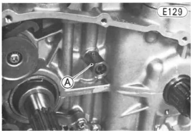
A. Relief Valve
Installation Note:
- Apply a non-permanent locking agent to the valve threads, and tighten it to 1.5 kg-m (11.0 ft-lbs) of torque.
EXTERNAL SHIFT MECHANISM
Removal:
- Remove the engine sprocket (or pulley) cover (Pg. 69). The clutch cable does not require removal from the clutch release.
- Remove the timing advancer (Pg. 77).
- Remove the right engine cover.
- Remove the clutch, primary sprocket, and primary chain (Pg. 78).
- Remove the external shift mechanism stop screws ⑤ (2), and take off the stop ⑧.

A. External Shift Mechanism
B. Stop
C. Screws
D. Return Spring Pin
- Move the shift mechanism arm ④ and overshift limiter ① out of their positions on the end of the shift drum and pull out the shift shaft ⑦.
External Shift Mechanism
E131

- Overshift Limiter
- Pawl Spring
- Return Spring Pin
- Shift Mechanism Arm
- Screw
-
Return Spring
-
Shift Shaft
- Shift Mechanism Stop
- Pedal Rubber
- Shift Pedal
- Bolt
Installation:
- Check that the external shift mechanism return spring pin ③ is not loose. If it is loose, remove it, apply a non-permanent locking agent to the threads, and tighten it.
- Check that the return spring is properly fitted on the shaft and that the pawl spring is on the two arms.

A. Pawl Spring
B. Return Spring
- Insert the shift shaft oil seal guide (special tool) in the crankcase oil seal. Install the external shift mechanism, and place the shift mechanism arm and overshift limiter on the shift drum pins.

A. Shift Shaft Oil Seal Guide (57001-264)
B. Overshift Limiter
C. Shift Mechanism Arm
- Install the external shift mechanism stop, and tighten its screws, applying a non-permanent locking agent to the screws.
- Install the clutch, primary sprocket, and primary chain (Pg. 79).
●Install the right engine cover.
●Install the timing advancer (Pg. 77).
●Install the engine sprocket (or pulley) cover (Pg. 69).
-Adjust the ignition timing (Pg. 18). - Fill the engine with oil, check the oil level (Pg. 26), and add more if necessary.
- Check the automatic side stand return mechanism, and adjust if necessary (Pg. 38).
84 DISASSEMBLY-ENGINE INSTALLED
OIL FILTER, BYPASS VALVE
Removal:
- Place an oil pan beneath the engine, and remove the engine drain plug.

A. Engine Drain Plug
B. Oil Filter Mounting Bolt
- Remove the filter mounting bolt and drop out the filter.
- Pull the filter off the mounting bolt. There is a spring seat and spring between the oil filter and the filter cover.
- To remove the bypass valve, drive the pin and drop out the spring and steel ball.
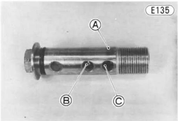
A. Pin
B. Steel Ball
C. Spring
Installation:
●Fit the steel ball and spring into the mounting bolt, and drive in the pin while pressing the spring.
- Check that the O rings on the filter mounting bolt and filter cover are all properly in place. Replace the O ring with a new one if deteriorated or damaged.
CAUTION
Using damaged or deteriorated O rings instead of replacing them with new ones will cause oil leaks and eventually result in little or no oil left in the engine. This will cause serious engine damage. The oil in the oil filter housing is pressurized by the engine oil pump, so these O rings must be inspected with special care. Look for discoloration
(indicating the rubber has deteriorated), hardening (the sides which face the mating surfaces are flattened), scoring, or other damage.
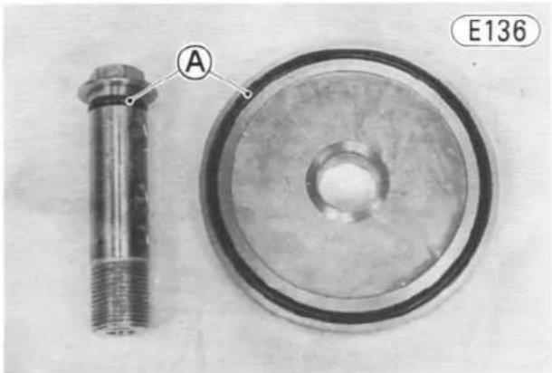
A. "O" Rings
- Apply a little engine oil to the O ring on the filter mounting bolt, fit the filter cover on the bolt, and install the spring and spring seat in this sequence.
- Apply a little engine oil on the oil filter grommets, and turn the filter mounting bolt to work the new filter into place while holding the filter steady. Be careful that the filter grommets do not slip out of place.
●Install the oil filter, tightening its bolt to 2.0 kg-m (14.5 ft-lbs) of torque. - Install the engine drain plug and aluminum gasket, and tighten the plug to 3.0 kg·m (22 ft·lbs) of torque. Use a new aluminum gasket, if it is damaged.
- Fill the engine with oil, check the oil level (Pg. 26), and add more if necessary.
Disassembly—Engine Removed
Table of Contents
FLOW CHART.... 86
ENGINE REMOVAL 88
CRANKCASE SPLIT 90
TRANSMISSION 95
Shift Drum 97
Drive Shaft 97
Output Shaft.... 98
BALANCER MECHANISM, MAIN BEARING CAP 99
CAMSHAFT CHAIN GUIDE (Front).... 102
CONNECTING ROD 102
CRANKSHAFT, CAMSHAFT CHAIN.... 103

FLOW CHART
Engine Removal
The following charts are intended to be aids to proper removal. Select the component you wish to remove and follow the arrows to that point on the chart.
![graph TD A["Motorcycle"] --> B["Mufflers"] A --> C["Left Footpeg"] A --> D["Automatic Side Stand Return Mechanism"] A --> E["Starter Motor Cover"] A --> F["Tachometer Cable Lower End"] A --> G["Left and Right Side Covers"] A --> H["Breather Hose"] A --> I["Rear Brake Light Switch"] B --> J["Drive Ch…](/content/2026/06/1261528/images/08729f1103391f10b901e113c002bbea0db46b0c8e23e53c3bbefbdf48c891cd.jpg)
NOTE: Action with a mark (★) requires special tool(s) for removal, installation, disassembly, or assembly.
FLOW CHART
Disassembly — Engine Removed
![graph TD A["Engine"] --> B["Contact Breaker Cover"] A --> C["Oil Pipe"] A --> D["Alternator Cover"] B --> E["Contact Breaker Mounting Plate"] E --> F["Timing Advancer"] F --> G["Right Engine Cover"] G --> H["Clutch, Primary Sprocket, Primary Chain"] H --> I["External Shift Mechanism"] I --> J["Shift…](/content/2026/06/1261528/images/0da19d03a36601f1307e763a9efdc6864653e58bf076eb9efc5c2e10ab7357b0.jpg)
NOTES: 1. Action that has been already done in the engine removal procedure is omitted. Action that is not necessarily required for engine disassembly off the motorcycle is also omitted. 2. Action with a mark ( ) requires special tool(s) for removal, installation, disassembly, or assembly.
ENGINE REMOVAL
Removal:
- Place an oil pan beneath the engine, and remove the engine oil drain plug and oil filter to drain out the oil.
- After draining the oil, install the drain plug with its aluminum gasket and tighten the plug to 3.0 kg-m (22 ft-lbs) of torque and install the oil filter, tighten its bolt to 2.0 kg-m (14.5 ft-lbs) of torque. Replace the aluminum gasket with a new one if it is damaged.
- Remove the fuel tank.
- Pull the spark plug leads off the plugs, and disconnect the ignition coil leads.
- Remove the bolts (2), and take the ignition coil off the frame together with its mounting bracket.
- Slide the clamp out of place, and pull the breather hose off the breather cover.
- Remove the carburetors (Pg. 52).
- Cover the carburetors with a clean cloth to keep dirt out of the carburetors, and set them on the workbench to avoid damaging the throttle cable and carburetors.
- Disconnect the tachometer cable lower end with pliers. There is a gasket in the knurled nut.

A. Tachometer Cable
B. Nut
- Remove the engine sprocket (or pulley) cover (Pg. 69). The clutch cable does not require removal from the clutch release.
- For chain driven models, remove the drive chain (Pg. 117).
- For the belt driven model, fully move the rear wheel forward so that the belt is too loose (Pg.32), and slide the belt off the pulleys.
- Remove the starter motor cover bolts and flat washers (2 ea), and take off the cover and gasket.
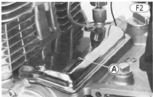
A. Starter Motor Cover
- Slide the rubber cap out of place, remove the nut and lockwasher, and free the starter motor lead from the starter motor terminal.
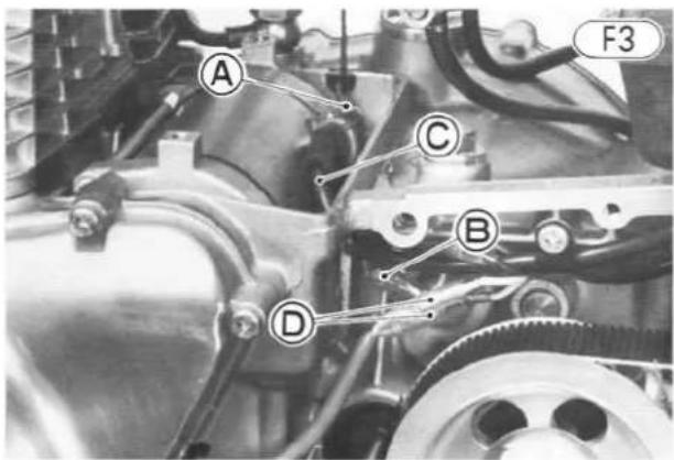
A. Nut
C. Starter Motor Lead
B. Neutral Switch Lead
D. Alternator Leads
●Disconnect the neutral switch lead from the switch.
●Disconnect the alternator yellow leads (2).
- Remove the lead clamp screw, take off the clamp, and free these leads from the engine.
- Remove the mufflers (Pg. 56),
- Remove the right footpeg mounting bolt and lock-washer, and take off the footpeg.
- Remove the rear brake light switch (Pg. 134).
- Remove the rear brake pedal return spring.
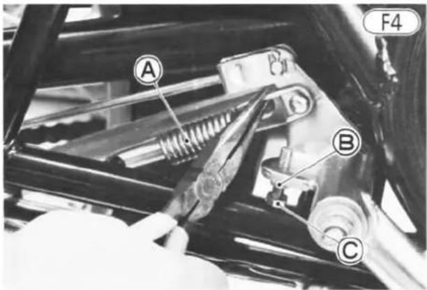
A. Brake Pedal Return Spring
C. Adjusting Bolt
B. Locknut
●Back the rear brake adjusting nut off to the end of the brake rod to give the pedal play. Loosen the brake pedal adjusting bolt locknut, and back out the adjusting bolt until the pedal is held down out of the way.
- Remove the straps and free the contact breaker lead from the frame down tube.
●Make sure that the following cables and leads are free, and properly positioned on the engine and frame so that they will not get damaged during engine removal: starter lead, clutch cable, tachometer cable, contact breaker lead, alternator lead, and throttle cable.
- Jack or lever the engine up slightly to take the weight off the engine mounting bolts.
- Remove the upper engine mounting bracket bolts (3), and take off the brackets. Each bolt has a lockwasher and nut.

A. Bolts
B. Brackets
C. Breather Cover
- Remove the bolts (4), and remove the breather cover and O ring.
- Remove the front engine mounting bracket short bolts ① and lockwashers on each side, and remove the long bolt ②. The long bolt has a self-locking nut, lockwasher and spacer.
- Remove the rear right upper mounting bracket bolts 3, 4 and lockwashers.
- Remove the self-locking nuts and lockwashers (4 ea) off the engine mounting bolts ⑤, ⑥, ⑦.
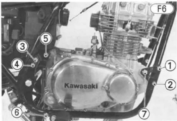

- Front Mounting Bracket Short Bolt
- Front Mounting Bracket Long Bolt
- Rear Right Upper Mounting Bracket Bolt
- Rear Right Upper Mounting Bracket Bolt
- Rear Upper Mounting Bolt
- Rear Lower Mounting Bolt
-
Front Mounting Bolt
-
Pull off the engine mounting bolts 5, 6, 7. Be careful not to damage the threads upon removal. The rear upper mounting bolt has a spacer and bracket, and the rear lower mounting bolt has a spacer.
- Lift up on the front of the engine until cylinder head cover stops just under the frame top tube, move it to the right so that the bottom of the engine clears the frame, and pull the engine out of the frame, top first and rear last.
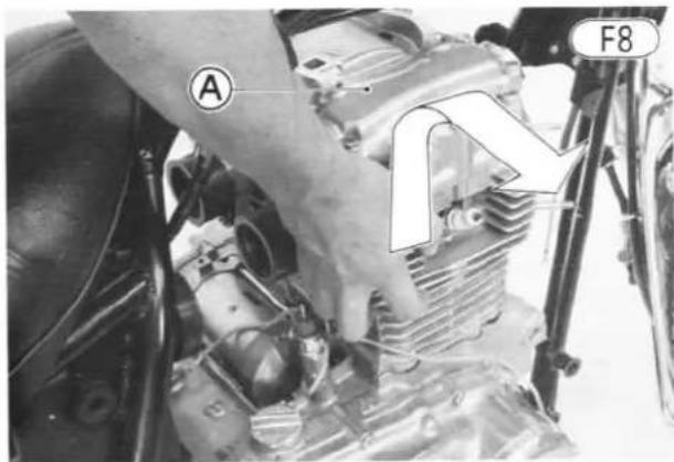
A. Cylinder Head Cover
Installation:
- Place the engine in the frame in the reverse of its removal.
- Loosely mount the engine mounting brackets as shown. See Table F1 for bolt identification. Each bracket bolt has a lockwasher. The front mounting bracket long bolt has a spacer, lockwasher, and self-locking nut.
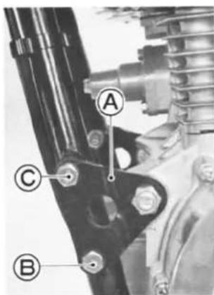
A. Mounting Bracket
B. Long Bolt
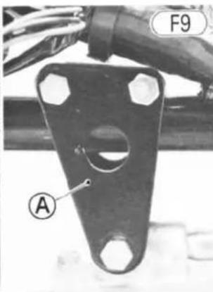
C. Short Bolt
- Lifting the engine as necessary so that the engine mounting bolt threads do not get damaged, insert the engine mounting bolts to the left side of the engine, and install the lockwashers and self-locking nuts finger tight. Each rear upper and lower mounting bolt has a spacer. The spacer for the lower mounting bolt has a groove (Fig. F10).

A. Lower Spacer
B. Upper Spacer
●After engine mounting bolt insertion, first tighten the bracket mounting bolts, and then the engine mounting bolts to the torque specified in Table F1.
NOTE: Some machines have one or more shims added to the lower spacer. After the nuts are tightened to the proper torque, check to see whether or not the spacer takes up all the space. If not, add one or more shims.

A. Shim(s)
- Install the breather cover and O ring.
- Apply a non-permanent locking agent to the threads of the cover bolts (4), and tighten them to 2.5 kg·m (18.0 ft·lbs) of torque.
- Install the right footpeg and lockwasher, and tighten the footpeg bolt.
- Turn in the rear brake pedal adjusting bolt, and install the rear brake pedal return spring.
●Install the rear brake light switch (Pg. 134).
●Run the wiring harness and the starter motor lead in front of the upper mounting bolt spacer.
- Run the starter motor lead through the crankcase hole, fit the lead to the starter motor terminal, and tighten the nut with the lockwasher. Slide the rubber cap back in place.
- Connect the neutral switch lead to the switch.
- Connect the alternator yellow leads (2).
- For chain driven model, install the drive chain (Pg. 118).
- For the belt driven model, fit the belt on the pulleys.
●Install the engine sprocket (or pulley) cover (Pg. 69).
●Install the mufflers (Pg. 57).
- Check that the gasket is in place, and connect the tachometer cable lower end to the cylinder head cover.
●Install the carburetors (Pg. 53).
●Run the oil pressure switch lead through the crankcase hole, and connect the lead to the oil pressure switch.
●Install the starter motor cover with the gasket, and tighten the cover bolts (2). Each bolt has a flat washer.
●Install the ignition coil and its bracket with the bolts, running the right spark plug lead between the upper brackets.
- Connect the ignition coil leads.
- Connect the spark plug lead on each spark plug.
●Install the fuel tank (Pg. 50).
●Fill the engine with oil, check the oil level (Pg. 26), and add more if necessary.
- Check the drive chain or belt (Pg. 30 or 31).
- Check the clutch (Pg. 25).
- Check the throttle cable (Pg. 21).
-Adjust the rear brake (Pg. 34).
- Adjust the rear brake light switch (Pg. 34).
- Check the automatic side stand return mechanism (Pg. 38), and adjust if necessary.
- Check the ignition timing, and adjust if necessary (Pg. 18).
- Check the carburetors (Pg. 22).
CRANKCASE SPLIT
Disassembly:
- Remove the engine (Pg. 88).
- Set the engine on a clean surface or, preferably, mount it on an engine stand.
Table F1 Engine Bolt Tightening Torque
| Bolt | Length | Torque | |
| Front Bracket Bolts | Lower 1 (2) | 60 mm | 2.5 kg·m (18.0 ft·lbs) |
| Upper 2 | 253 mm | ||
| Rear Right UpperBracket Bolts | Long 3 | 40 mm | |
| Short 4 | 25 mm | ||
| Upper Bracket Bolts (3) | 55 mm | 2.5 kg·m (18.0 ft·lbs) | |
| Engine Mounting Bolts | Rear Upper 5 | 220 mm | 4.0 kg·m (29 ft·lbs) |
| Rear Lower 6 | 292 mm | ||
| Front 7 (2) | 50 mm | ||
- Remove the engine sprocket (or pulley), output shaft collar, and O ring (Pg. 69), if the output shaft assembly is to be diassembled.

A. Holder (57001-307)
B. Engine Sprocket
- Remove the alternator cover, and remove the alternator rotor and starter motor clutch (Pg. 71).

A. Holder (57001-308)
C. Sprockets
B. Rotor
D. Chain
- Remove the starter motor chain and sprockets (Pg. 73).
- Remove the oil pipe (Pg. 68).

A. Use a wrench to hold the upper end.
- Remove the starter motor (Pg. 74).
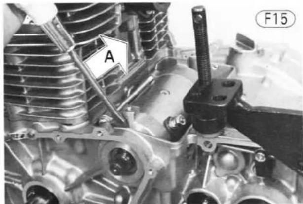
A. Pry the motor loose.
- Remove the contact breaker and its mounting plate (Pg. 76).
- Remove the automatic timing advancer (Pg. 77).

A. Timing Advancer
- Remove the right engine cover.
- Remove the clutch, primary chain, and primary sprocket (Pg. 78).

A. Clutch
B. Primary Chain
C. Primary Sprocket
92 DISASSEMBLY-ENGINE REMOVED
- Remove the external shift mechanism (Pg. 82).

A. Shift Mechanism Stop
B. Shift Shaft
- Remove the upper crankcase half bolts (5).
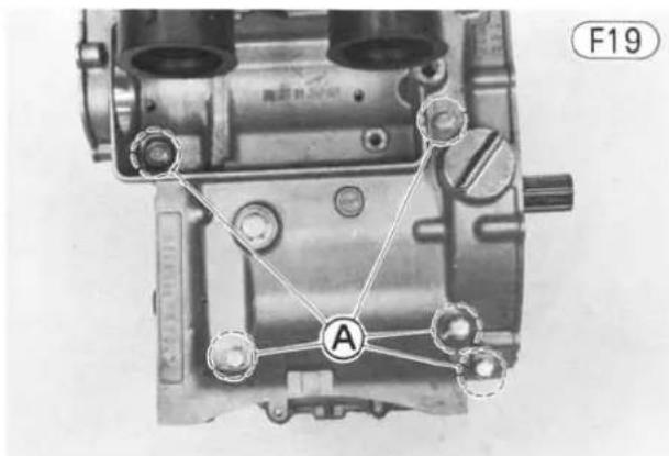
A. Upper Crankcase Half Bolts
●Turn the engine upside down.
- Remove the 6 mm lower crankcase half bolts (11) and 8 mm bolts (4).

A. 6 mm Bolts
B. 8 mm Bolts
●Pry the three points to split the two crankcase halves apart, and lift off the lower crankcase half.
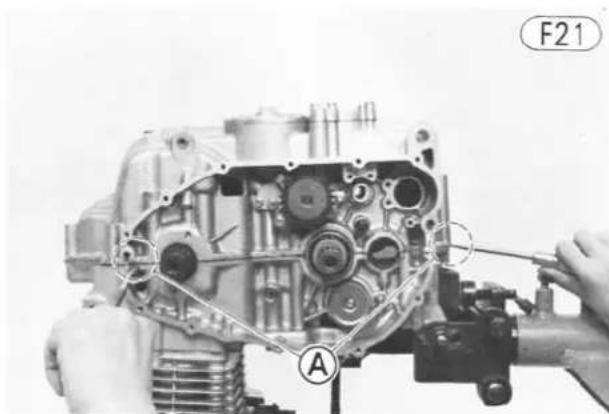
A. Pry Point
- Remove the circlip, oil seals (2), and oil passage O rings (2).

A. Output Shaft Oil Seal
B. Push Rod Oil Seal
C. "O" Rings
- Remove the drive shaft and output shaft assembly.
Assembly:
NOTE: The upper crankcase half, the lower crankcase half, and the crankshaft main bearing cap are machined at the factory in the assembled state, so the crankcase halves and main bearing cap must be replaced together as a set.
- With a high flash-point solvent, clean off the mating surfaces of the crankcases halves and wipe dry.
- Check to see that the following parts are in place on both the upper crankcase half and the lower crankcase half, and blow the oil passages clean with compressed air. Check that the drive and output shaft set pins (2) protrude 1.7 \~ 2.5 mm from their bearing housings. The flat side of each oil passage O ring must face to the upper crankcase half or main bearing cap.

A. Flat Side
Upper crankcase half:
Knock pins (2); oil passage O rings (2) (use a new one if deteriorated or damaged); oil passage nozzle; drive shaft and output shaft set rings (2); and drive shaft and output shaft set pins (2).

A. Knock Pin
C. Set Rings
E. Nozzle
B. "O" Rings
D. Set Pin
Lower crankcase half:
Crankshaft bearing inserts (2); output shaft oil receiver; and sump plate.
NOTE: When installing the sump plate, apply a non-permanent locking agent to the sump plate screws.
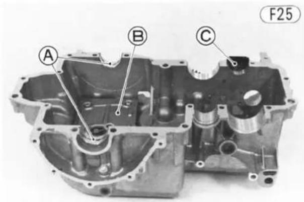
A. Bearing Inserts
C. Oil Receiver
B. Sump Plate
- Check that the crankshaft main bearing cap is tightened to the correct amount of torque (Pg. 43).
- To set the shift drum in neutral position, turn the shift drum so that the projection on the operating plate contacts with the neutral switch pin.

A. Projection
B. Neutral Switch Pin
- Fit the output and drive shaft assemblies on the upper crankcase hall. When installing output and drive shafts, the crankcase set pins must go into the holes in the needle bearing outer races, and the set rings must fit into the grooves in each ball bearing.

Make sure the crankcase set pins are properly aligned to avoid damage to the on installation.
- Check that the side clearance of the output shaft 1st gear and side clearance of the drive shaft 2nd gear are within the standard value. If the clearance exceeds the standard value, add the washer (0.5 mm thickness).

A. Output Shaft 1st Gear
B. Thickness Gauge

A. Drive Shaft 2nd Gear
B. Thickness Gauge
94 DISASSEMBLY-ENGINE REMOVED
Table F2 Side Clearance
| Standard |
| under 0.5 mm |
- Install the oil seal next to the output shaft ball bearing.
- Install the clutch push rod oil seal next to the drive shaft needle bearing, and insert the push rod through the oil seal and into the drive shaft, applying a high temperature grease to the push rod. The ridge on the oil seal must fit in its crankcase groove.
- Apply a little engine oil to the transmission gears, ball bearings, crankshaft bearing inserts, and shift forks.
- Apply a liquid gasket to the mating surface of the lower crankcase half in the areas shown in Fig. F29.
CAUTION
If liquid gasket adheres to any areas not indicated, the engine oil passages may be obstructed, causing engine seizure.
Liquid Gasket Applied Area
F29

- Fit the lower crankcase half on the upper crankcase half. Be careful that the oil seals do not slip out of place.
- Install and lightly tighten the lower crankcase half 8 mm bolts (4) and 6 mm bolts (11).
●Tighten the 8 mm bolts first about 1.5 kg·m (11.0 ft·lbs) of torque, following the tightening sequence numbers on the lower crankcase half, and then tighten
them to 2.5 kg-m (18.0 ft-lbs) of torque in the same sequence.
● Tighten the 6 mm bolts to 1.0 kg·m (87 in-lbs) of torque.
●Install the circlip into the groove next to the clutch push rod oil seal.

A. Circlip
B. Oil Seal
- Check to see that the drive shaft and output shaft turn freely, and, spinning the output shaft, shift the transmission through all gears to make certain there is no binding and that all gears shift properly.
●Turn the engine upside down.
● Tighten the upper crankcase half bolts (5) to 1.0 kg-m (87 in-lbs) of torque.
●Install the external shift mechanism (Pg. 83). - Check that the oil pump drive gear is installed, and the oil pressure relief valve is installed.

A. Relief Valve
B. Pump Drive Gear
- Install the clutch, primary chain, and primary sprocket (Pg. 79). Check the clutch hub side clearance, and adjust if necessary (Pg. 79).
- Install the right engine cover. Be sure to include the contact breaker lead clamp with the right engine cover front screw.

A. Lead Clamp
●Install the timing advancer (Pg. 77).
- Install the contact breaker (Pg. 76), and install the breaker cover and gasket.
●Install the starter motor (Pg. 74).
●Install the oil pipe (Pg. 68).
●Install the starter motor chain and sprockets (Pg. 74).
●Install the alternator rotor and starter motor clutch, and install the alternator cover and gasket (Pg. 72).
- Install the O ring, collar, and engine sprocket or pulley (Pg. 69).
●Install the engine (Pg. 89).
- Fill the engine with oil, check the oil level (Pg. 26), and add more if necessary.
- Carry out the adjustment procedures listed at the end of the engine installation section (Pg. 90).
●Pull out the shift rod 37, and remove the two shift forks 35, 36.
- Remove the operating plate circlip 32 and operating plate 33.
- Drop out the operating plate pin 34 .
- Remove the 3rd/4th gear shift fork cotter pin 24, and pull out the shift fork guide pin 25.
●Pull the shift drum 27 out of the crankcase and the 5th/6th gear shift fork 26 will come out.
Installation:
- Apply a little engine oil to the shift drum. Insert the shift drum into the crankcase, and install the 5th/6th gear shift fork with the part which houses the guide pin facing the crankshaft.

A. Crankshaft
B. Guide Pin Hole
TRANSMISSION
Removal:
- Remove the engine (Pg. 88).
- Set the engine on a clean surface or, preferably, mount it on an engine stand.
- Split the crankcase (Pg.90).
- Remove the shift drum positioning bolt 20, aluminum washer 21, spring 22, and pin 23.
- Remove the screws (2) 39, and take off the shift drum guide plate 38.

A. Guide Plate
B. Shift Rod
- Fit the operating plate pin onto the shift drum, install the operating plate with its projection facing the neutral switch, and install the circlip.

A. Pin
B. Projection
- Put the shift fork guide pin into the 5th/6th gear shift fork. The guide pin rides in the middle groove of the three guide pin grooves.
- Insert a new cotter pin through the shift fork and guide pin, and spread its ends.

- Circlip
- Bushing
- Bearing Outer Race
- Needle Bearing
- Washer(s)
- 2nd Gear (D)
- Circlip
- Splined Washer
- 6th Gear (D)
- Bushing
- Splined Washer
- Circlip
- 3rd/4th Gear (D)
- Circlip
- Washer
- 5th Gear (D)
- Drive Shaft
- Ball Bearing
- Collar
- Positioning Bolt
- Aluminum Washer
- Spring
- Pin
- Cotter Pin
- Shift Fork Guide Pin
- 5th/6th Gear Shift Fork
- Shift Drum
- Shift Drum Pin
- Shift Drum Pin Plate
- Screw
- Neutral Switch
- Circlip
- Operating Plate
- Pin
- Shift Fork (2nd/3rd)
- Shift Fork (1st/4th)
- Shift Rod
- Shift Drum Guide Plate
- Screw
- Nut
- Splined Washer
- Engine Sprocket
- Collar
- O Ring
- Oil Seal
- Ball Bearing
- Output Shaft
- Bushing
- 2nd Gear (O)
- Washer
- Circlip
- Steel Balls
- 3rd Gear (O)
- Washer
- 4th Gear (O)
- Bushing
- Splined Washer
- Circlip
- 5th Gear (O)
- 6th Gear (O)
- Circlip
- Splined Washer
- 1st Gear (O)
- Washer(s)
- Needle Bearing
- Bearing Outer Race
- Circlip
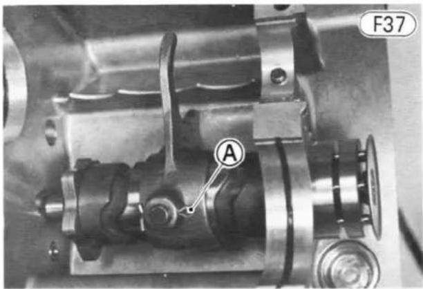
A. Cotter Pin
- Apply a little engine oil to the shift rod. - Insert the rod, running it through the 1st/4th and 2nd/3rd shift forks. Fit each shift fork guide pin into the shift drum groove.
NOTE: Both 1st/4th shift fork and 2nd/3rd shift fork are identical.
●Fit the shift drum guide plate, tighten its screws (2), and stake each screw head with a punch to prevent loosening.
- Install the shift drum positioning pin, spring, and bolt with an aluminum washer (use a new one if it is damaged), and tighten it to 3.5 kg-m (25 ft-lbs) of torque.
●Assemble the crankcase (Pg. 92).
●Install the engine (Pg. 89).
- Fill the engine with oil, check the oil level (Pg. 26), and add more if necessary.
●Carry out the adjustment procedures listed at the end of the engine installation section (Pg. 90).
Shift Drum
Disassembly:
- Remove the screw 30 and the shift drum pin plate 29.
●Pull out the pins 28 (6).

A. Pins
Assembly Note:
●Install the shift drum needle bearings from the right side of the crankcase using a suitable driver. Press them into place until the bearing right end is even with the end of the hole.
Drive Shaft
Disassembly:
- Remove the needle bearing outer race 3.
- Remove the circlip ①, and pull off the needle bearing ④, washer(s) ⑤, and 2nd gear ⑥.
- Remove the circlip ⑦, and pull off the splined washer ⑧, 6th gear ⑨, bushing ⑩, and splined washer ⑪.
- Remove the circlip 12, and pull off the 3rd/4th gear 13.
- Remove the circlip 14, and pull off the washer 15 and 5th gear 16.
- Remove the ball bearing 18 and collar 19 using the bearing puller and adapter (special tools).
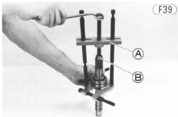
A. Bearing Puller (57001-135)
B. Adapter (57001-166)
Assembly Notes:
- Install the drive shaft ball bearing and collar using the transmission circlip driver (special tool).

A. Transmission Circlip Driver (57001-380)
- To install a circlip without damage, fit the circlip onto the shaft expanding it onto enough to install it, and use a suitable gear to push the circlip into place.
- Replace any circlips that were removed with new ones. Install the circlip so that the opening coincides with one of the splined grooves in the output shaft (Fig. F41).
- Install the splined washer so that its teeth do not coincide with the circlip opening (Fig. F41).
98 DISASSEMBLY—ENGINE REMOVED
Circlip, Splined Washer Installation
F41
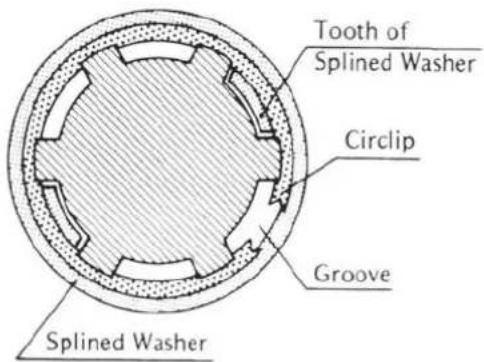
- When assembling 3rd/4th gear and the 6th gear bushing to the drive shaft, align the oil holes with the holes in the shaft.
- The drive shaft gears can be recognized by size, the gear with smallest diameter being 1st gear, and the largest one being top gear. Be sure that all parts are put back in the correct sequence, facing the proper direction, and all circlips and washers are properly in place.
Drive Shaft Gears
F42

Proper sequence starting with 1st gear (part of drive shaft) is: 1st gear, 5th gear (face the flat side of the gear to the 1st gear), washer, circlip, 3rd/4th gear (face 4th gear side to the right), circlip, splined washer, bushing, 6th gear (face the dogs to 3rd gear), splined washer, circlip, 2nd gear, washer(s), needle bearing, circlip, and needle bearing outer race.
Output Shaft
Disassembly:
●Pull off the needle bearing outer race 66.
- Remove the circlip 67 , and pull off the needle bearing 65 , washer(s) 64 , and 1st gear 63 .
- 5th gear 59 has three steel balls (3) assembled into it for neutral positioning. To remove this gear with the balls, quickly spin the shaft in a vertical position while holding 3rd gear 53 or 4th gear, and pull off 5th gear upwards.
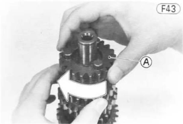
A. 5th Gear
- Remove the circlip 58, and pull off the splined washer 57, 4th gear 55, washer 54, 3rd gear 53, bushing 56, and splined washer 62.
- Remove the circlip 61, and pull off the 6th gear 60.
- Remove the circlip 51 , and pull off the washer 41 , 2nd gear 49 , and bushing 48 .
●Using the bearing puller (special tool), remove the output shaft ball bearing 46.
Assembly·Notes:
- Install the output shaft ball bearing using the transmission circlip driver (special tool).
- To install a circlip without damage, fit the circlip onto the shaft expanding it only enough to install it and use a suitable gear to push the circlip into place.
- Replace any circlips that were removed with new ones. Install the circlip so that the opening coincides with one of the splined grooves in the driver shaft (Fig. F41).
- Install the splined washer so that its teeth do not coincide with the circlip opening (Fig. F41).
- Do not use grease on the three balls during assembly; these balls must be able to move freely.
- When assembling 6th gear, the 2nd gear bushing, and the 3rd/4th gear bushing to the output shaft, align the oil holes with the holes in the shaft.

A. Align the oil holes.
- The output shaft gear sizes are opposite from those of the drive shaft gears, the largest being 1st gear and the smallest being top gear. Be sure that all parts are put back in the correct sequence, and facing the proper direction, and that all circlips and washers are properly in place.
Output Shaft Gears
F45
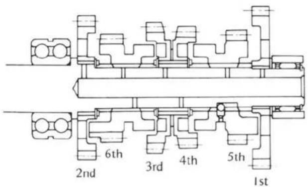
Proper sequence starting with 2nd gear is: bushing (align the oil holes), 2nd gear (face the flat side of the gear to the ball bearing), washer, circlip, 6th gear (face the fork groove side away from 2nd gear), circlip, splined washer, bushing (align the oil holes), 3rd gear (face the side with the dog recesses to the left), washer, 4th gear (face the side with the dog recesses to the right), splined washer, circlip, 5th gear (face the fork groove side to the left) and steel balls (3), 1st gear (face the flat side of the gear to the right), washer(s), needle bearing, circlip, and needle bearing outer race.
BALANCER MECHANISM, MAIN BEARING CAP
Removal:
- Remove the engine (Pg. 88).
- Set the engine on a clean surface or, preferably, mount it on an engine stand.
- Split the crankcase (Pg. 90).
- Remove the main bearing cap 10 mm bolts (4) and 8 mm bolts (4), and take off the main bearing cap and balance mechanism.
Installation:
NOTE: The upper crankcase half, the lower crankcase half, and the crankshaft main bearing cap are machined at the factory in the assembled state, so the crankcase halves and the main bearing cap must be replaced together as a set.
- With a high flash-point solvent, clean off the mating surfaces of the upper crankcase half and main bearing cap, and wipe dry.
- Check that the knock pins (4), main bearing inserts (2), and O ring are in place. If the O ring is damaged or deteriorated, replace it with a new one.
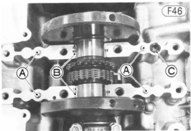
A. Knock Pins
C. "O" Ring
B. Bearing Inserts
- Check that the main bearing inserts (2) are in place.
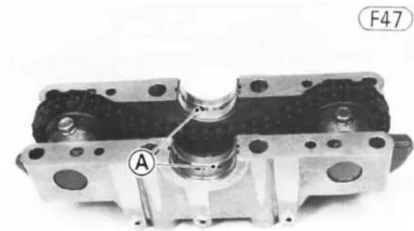
A. Bearing Inserts
- Temporarily install the timing advancer, and, with a 17 mm wrench, turn the crankshaft so that the crankshaft oil holes are even with the upper crankcase half surface, with flywheels positioned up.

A. Oil Holes
100 DISASSEMBLY-ENGINE REMOVED
- Check to see that the balancer chain and balancer sprockets are properly fitted. For the front sprocket, the plated link must fit on the sprocket tooth with the punch mark. For the rear sprocket, the 4th plated link counted from the front must fit on the sprocket tooth with the punch mark.
NOTE: There are four plated links, and, with the chain in the position mentioned above, the 2nd and 3rd plated links counted from the front will be located on the main bearing cap mating surface side (Fig. F51).
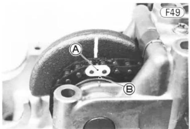
A. Plated Link
B. Punch Mark
- Fit the main bearing cap on the upper crankcase half with the arrow on the main bearing cap pointing forward, engaging the middle link between the 2nd plated
link and the 3rd plated link with the top tooth of the sprocket on the crankshaft.

A. Front
B. Arrow
- Check that the line mark on each balancer weight aligns with the mark on the main bearing cap, and that the sprocket tooth with the punch mark engages the balancer chain plated link. If not, lift off the balancer mechanism, and correct the timing.
●Install the main bearing cap 10 mm bolts (4) and 8 mm bolts (4), and first tighten the 8 mm bolts about 1.5 kg·m (11 ft·lbs) of torque and the 10 mm bolts about 2.5 kg·m (18 ft·lbs) of torque, following the tightening sequence numbers on the main bearing cap, and then tighten the 8 mm bolts to 2.5 kg·m (18 ft·lbs) of torque and the 10 mm bolts to 4.0 kg·m (29 ft·lbs) of torque in the same sequence.
Balancer Chain Timing
F51

- Plated Link
- Balancer Sprocket Punch Mark
-
Balancer Weight Line Mark
-
Main Bearing Cap
- Main Bearing Cap Mark
- Crankshaft Sprocket Top Tooth

A. Main Bearing Cap
●Install the O ring onto the top of the main bearing cap.
●Assemble the crankcase (Pg. 92).
●Install the engine (Pg. 89).
- Fill the engine with oil, check the oil level (Pg. 26), and add more if necessary.
- Carry out the adjustment procedures listed at the end of the engine installation section (Pg. 90).
Disassembly:
- Remove the main bearing inserts (2) 16.
- Remove the balancer weight bolts (2) 7
●Pull out the balancer weight shafts (2) ③, and take off the washers ①, weights 6 and sprockets 2 (2 ea).
●Tapping lightly with a mallet, separate the sprocket 2 and balancer weight 6. The springs 4 and pins 5 (4 ea) may be removed.
- Remove the balancer chain guide screws (2) 12, and take off the guide ③ and balancer chain 8.
- Remove the balancer chain guide screw ⑨, and take off the guide 14.
Assembly:
●Fit the balancer chain guide, and tighten its screw applying a non-permanent locking agent to its threads. After tightening the guide screw, bend the other end of the guide over the side of the main bearing cap.
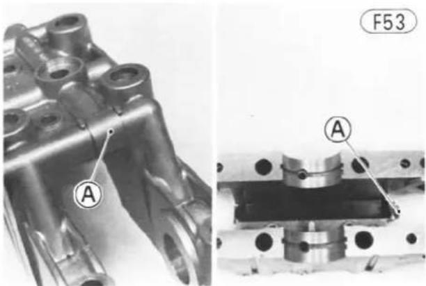
A. Chain Guide End
B. Apply a non-permanent locking agent
Balancer Mechanism
F54

- Bolt
- Bolt
- Screw
- Chain Guide
- Chain Guide
- Main Bearing Cap
- Bearing Insert
102 DISASSEMBLY-ENGINE REMOVED
- Install the balancer chain guide with the chain, and tighten its screws (2) applying a non-permanent locking agent on the screws. The balancer chain plated links must face the engine alternator side.
- With the springs and pins (4 ea) all in place in the inner circumference of the balancer weight, install the sprocket. The punch mark on the sprocket must face out (opposite side from the balancer weight), with the sprocket positioned as shown.

A. Punch Mark
B. Balancer Weight
- Move each spring to the furthest point outward in its space so that the springs will not hinder inserting the balancer shaft through the weight.
- Install the balancer weight and sprocket assemblies through the balancer chain, and fit the washer on each balancer sprocket side (Fig. F56).

A. Washer
- Apply oil to each shaft and insert them, keeping the chain on the sprockets. Match the hole in the shaft with the hole in the balancer weight. Be sure that the washers are in place between each sprocket and the main bearing cap.
●Tighten the balancer weight bolts (2) to 1.5 kg-m (11.0 ft-lbs) of torque.
●Install the main bearing inserts (2).
CAMSHAFT CHAIN GUIDE (FRONT)
Removal:
- Remove the engine (Pg. 88).
- Set the engine on a clean surface or, preferably, mount it on an engine stand.
- Remove the cylinder head cover (Pg. 57).
- Remove the camshaft and camshaft sprocket (Pg. 60).
- Remove the cylinder head (Pg. 62).
- Remove the cylinder block (Pg. 65).
●Split the crankcase (Pg. 90). - Remove the balancer mechanism (Pg. 99).
- Remove the retaining pin, and take out the front camshaft chain guide pivot pin and guide.

A. Retaining Pin
C. Chain Guide
B. Pivot Pin
Installation:
- Install the front camshaft chain guide, insert the guide pivot pin, and install the retaining pin.
●Install the balancer mechanism (Pg. 99).
●Assemble the crankcase (Pg. 92).
• Install the cylinder block (Pg. 65).
●Install the cylinder head (Pg. 62).
●Install the camshaft and camshaft sprocket (Pg. 60).
●Install the cylinder head cover (Pg. 58).
●Install the engine (Pg. 89). - Fill the engine with oil, check the oil level (Pg. 26), and add more if necessary.
- Carry out the adjustment procedures listed at the end of the engine installation section (Pg. 90).
CONNECTING ROD
Removal:
- Remove the engine (Pg. 88).
- Set the engine on a clean surface or, preferably, mount it on an engine stand.
- Remove the cylinder head cover (Pg. 57).
- Remove the camshaft and camshaft sprocket (Pg. 60).
-
Remove the cylinder head (Pg. 62).
-
Remove the cylinder block (Pg. 65).
- Remove the pistons (Pg. 66).
●Split the crankcase (Pg. 90). - Remove the nuts (4) and pull off the connecting rod big end caps.
CAUTION
Do not allow the big end cap bolts to bump against the crankshaft journals to
prevent damage.
- Remove the connecting rod bearing insert halves from the connecting rod big ends and the big end caps.
NOTE: It is recommended that the connecting rod big end cap bolts not be removed. This is to keep the alignment of the connecting rods and the big end caps.
Installation Notes:
- Apply engine oil to the connecting rod bearing inserts.
- When installing new connecting rods, use connecting rods having the same weight mark. This weight mark, indicated using a capital letter, is stamped on the connecting rod big end.
- The connecting rod big end cap is machined with the connecting rod as a set, so fit them together so that the weight marks align. The big end cap must be replaced together with the connecting rod as a set.
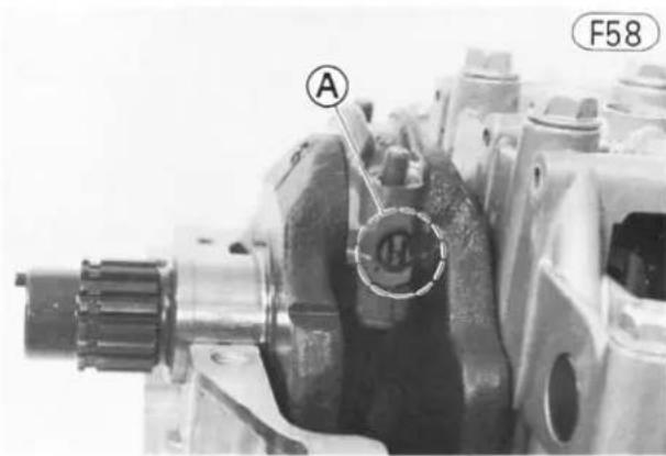
A. Weight Mark (Alphabet)
- If a new crankshaft and/or connecting rod is used, select the proper bearing insert in accordance with the combination of the connecting rod and the crankshaft marks (Fig. F59). If the crankshaft is not replaced, first measure the diameter of the connecting rod journal, mark its flywheel in accordance with the diameter (Pg. 168), and then select the proper bearing insert in accordance with Table F3.
Table F3 Bearing Insert Selection
| Crank-shaft Marking\Con-Rod Marking | ○ | No mark |
| ○ | BlackP/N: 92028-1098 | BrownP/N: 92028-1099 |
| No mark | GreenP/N: 92028-1097 | BlackP/N: 92028-1098 |

A. Color Mark
B. Connecting Rod Mark (Circle)
C. Crankshaft Mark (Circle)
5. Hand tighten both nuts first, and then tighten each nut to 3.7 kg-m (27 ft-lbs) of torque.
CRANKSHAFT, CAMSHAFT CHAIN Removal:
- Remove the engine (Pg. 88).
- Set the engine on a clean surface or, preferably, mount it on an engine stand.
- Remove the cylinder head cover (Pg. 57).
- Remove the camshaft and camshaft sprocket (Pg. 60).
- Split the crankcase (Pg. 90).
- Remove the balancer mechanism (Pg. 99).
- Remove the nuts (4) and pull off the connecting rod big end caps.
CAUTION To prevent damage to the crankshaft journals, do not allow the big end cap bolts to bump against them.
●Lift off the crankshaft with the camshaft chain.
●Slip the camshaft chain off the crankshaft.
Installation:
NOTE: If a new crankshaft and/or connecting rod is used, select the proper bearing insert in accordance with the combination of the connecting rod and crankshaft marks (Fig. F59, Table F3).
- If a new crankshaft, crankcase halves, and/or main bearing cap are used, select the proper bearing insert in accordance with the combination of the crankcase and crankshaft marks. If the crankcase only is replaced with a new one, first measure the diameter of the
104 DISASSEMBLY-ENGINE REMOVED
crankshaft journal, mark its flywheel in accordance with the diameter (Pg. 170), and then select the right bearing inserts in accordance with Table F4 (Fig. F60 and F61).
Table F4 Main Bearing Insert Selection
| Crankcasemarkingshaft Marking | ○ | No mark |
| 1 | BrownP/N: 92028-1102 | BlackP/N: 92028-1101 |
| No mark | BlackP/N: 92028-1101 | BlueP/N: 92028-1100 |

A. Marking

A. Marking
●Apply engine oil to the main bearing inserts.
●Blow the oil passages clean with compressed air.
●Apply engine oil to the crankshaft bearing inserts.
●Fit the camshaft chain back onto the sprocket and set the crankshaft back in its place on the upper crankcase half.

A. Crankshaft
B. Camshaft Chain
- Fit the connecting rod big end cap on the connecting rods the weight marks align (Fig. F58).
NOTE: The connecting rod big end cap is machined with the connecting rod as a set, so fit them together so that the weight marks align. The big end cap must be replaced together with the connecting rod as a set.
●Hand tighten both nuts first, and then tighten each nut to 3.7 kg-m (27 ft-lbs) of torque.
●Install the balancer mechanism (Pg. 99).
●Assemble the crankcase (Pg. 92).
• Install the camshaft and camshaft sprocket (Pg. 60).
●Install the cylinder head cover (Pg. 58).
●Install the engine (Pg. 89). - Fill the engine with oil, check the oil level (Pg. 26), and add more if necessary.
- Carry out the adjustment procedures listed at the end of the engine installation section (Pg. 90).
Disassembly—Chassis
Table of Contents
FLOW CHART....106
WHEEL, BRAKES, DRIVE CHAIN (BELT)
FRONT WHEEL.... 107
FRONT DISC BRAKE (KZ440A, C, D) 113
DRIVE CHAIN (KZ440A, B, C) 117
DRIVE BELT (KZ440D) 118
REAR WHEEL, REAR BRAKE 118
TIRE, TUBE 123
RIM (KZ440B) 124
SPOKE (KZ440B) 124
CABLES
FRONT BRAKE (KZ440B) 125
CLUTCH....125
THROTTLE 126
SPEEDOMETER....127
TACHOMETER 128
LIGHTS
HEADLIGHT 129
INDICATOR LIGHTS 130
TURN SIGNAL LIGHT 130
TURN SIGNAL ASSEMBLY 130
SPEEDOMETER, METER LIGHT 131
TACHOMETER, METER LIGHT, INDICATOR LIGHTS..... 132
TAIL/BRAKE LIGHT 132
SWITCHES
IGNITION....133
FRONT BRAKE LIGHT 133
REAR BRAKE LIGHT.... 134
STEERING
HANDLEBAR....134
STEERING STEM 135
STEERING STEM BEARING 138
SUSPENSION
FRONT FORK....139
SWING ARM 142
This chart is intended to be aids to proper removal. Select the component you wish to remove and follow the arrows to that point on the chart.
FLOW CHART
Disassembly – Chassis
![graph TD A["Motorcycle"] --> B["Headlight Unit"] A --> C["Tachometer Cable"] A --> D["Speedometer Cable"] A --> E["Front Brake Cable (KZ440-B)"] A --> F["Caliper"] A --> G["Fuel Tank"] A --> H["Throttle Cable"] A --> I["Rear View Mirrors"] A --> J["Clutch Cable Upper End"] A --> K["Left Footpeg"] A…](/content/2026/06/1261528/images/c19dec3eca9ca33dcd0a50c69d11b0a739eb36d41408ecea6762497a3f72e57c.jpg)
NOTE: Action with a mark (★) requires special tool(s) for removal, installation, disassembly, or assembly.
FRONT WHEEL
Removal (KZ440A, C, D):
- Disconnect the lower end of the speedometer cable with pliers.

A. Speedometer Cable
B. Axle Nut
- Remove the front axle nut.
- Use a jack under the engine to lift the front of the motorcycle.
●Holding the front wheel to facilitate axle removal, pull out the axle, and then remove the wheel from the motorcycle.
CAUTION
Do not lay the wheel down on the CAUTION brake disc. This can damage or warp the disc. Place blocks under the wheel so the disc does not touch the ground.
- Insert a wood wedge (4\~5 mm thick) between the disc brake pads. This prevents the pads from being moved out of their proper position, should the brake lever be squeezed accidentally.
Installation (KZ440A, C, D):
- Remove the wedge from between the disc brake pads.
- Check that the speedometer gear housing is properly fitted on the front hub, and check that the collar is on the right side of the hub.
NOTE: There are two types of speedometer gear construction. If the speedometer gear is driven by the speedometer gear receiver, fit the speedometer gear housing onto the hub so that the receiver fits in the hub recesses.

A. Speedometer Gear Receiver
B. Recesses
If the speedometer gear is driven by the speedometer gear drive, install the speedometer gear housing so that it fits in the speedometer gear drive notches. When properly fitted, the clearance between the speedometer gear housing and the gear drive holding plate is a little less than 3 mm.

A. Notches
B. Less than 3 mm
●Hold the front wheel in its place between the front fork tubes, and insert the axle from the right.
●Install the front axle nut finger tight.
●Turn the speedometer gear housing counterclockwise until it stops. Be sure that the small projection on the gear housing does not catch on the lower part of the left tube.

A. Projection
B. Speedometer Gear Housing
●Holding the axle with an open end wrench so that it does not turn, tighten the axle nut to 6.5 kg-m (47 ft-lbs) of torque.
- Insert the speedometer inner cable into the housing while turning the wheel so that the slot in the end of the cable will seat in the tongue of the speedometer pinion. Tighten the cable nut with pliers.
- Check the front brake.
WARNING The front brake lever must be pumped to move the brake pads into operating position. If this is not done, the first few applications of the brake may be ineffective and an unsafe riding condition could result.
Front Hub Disassembly (KZ440A, C, D):
- Pull the speedometer gear housing ② and collar ⑳ off the front hub.
●Take the wheel cap 74 off the right side of the hub.
●Unscrew the bolts (4), and remove the disc and holding plate 17.
●Pry out the grease seal 23 on the right side, and remove the circlip 22.
Front Hub (KZ440A, C, D)

A. Grease Seal

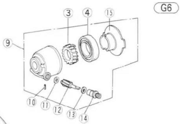
- Axle Nut
- Speedometer Gear Housing
- Speedometer Gear
- Grease Seal
- Gear Receiver
- Washer
- Circlip
- Speedometer Gear Housing Assembly (gear receiver type)
- Speedometer Gear Housing Assembly (gear drive type)
- Pin
- Washer
- Speedometer Pinion
- Washer
- Bushing
- Speedometer Gear Drive
- Disc Mounting Bolts
- Plate
- Ball Bearing
- Distance Collar
- Collar
- Ball Bearing
- Circlip
- Grease Seal
- Wheel Cap
- Washer
- Screws
- Wheel
- Front Axle
- Insert a metal rod from the right side, tap the inner race of the left side ball bearing 18 evenly, and remove the ball bearing. The distance collar 19 will come out when the bearing is removed.
Ball Bearing Removal
G7

●Tap out the other ball bearing 21.
Front Hub Assembly Notes (KZ440A, C, D):
- Inspect the bearings, and replace them if necessary (Pg. 193).
- Before installing the wheel bearings, blow any dirt or foreign particles out of the hub with compressed air. Lubricate the ball bearings (Pg. 193).
- Install the ball bearings using the bearing driver and the bearing driver holder (special tools) with the shield of each bearing facing outside. Install the left bearing first.
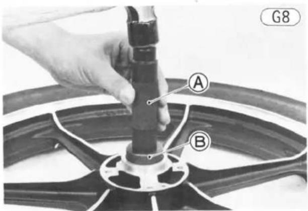
A. Bearing Driver Holder (57001-139)
B. Bearing Driver (57001-288) for #6302 Bearing Bearing Driver (57001-282) for #6202 Bearing
-
Put the distance collar in the hub so that the flange of the collar is on the left side, then install the right bearing.
-
Install the grease seal using the bearing driver and the bearing driver holder (special tools: P/N 57001-296, 57001-139).
- Tighten the disc mounting bolts (4) to 3.3 kg-m (24 ft-lbs) of torque.
- After installing the disc on the hub, check disc run-out (Pg. 201).
Removal (KZ440B):
- Jack or prop up the engine so that the front wheel is off the ground.
- Slide the cable dust cover out of its position on the outer cable end.
- Screw off the adjusting nut, and free the brake cable from the brake panel. Also remove the brake cable joint.

A. Cotter Pin
B. Adjusting Nut
C. Brake Cable
D. Cable Retaining Bolt
- Remove the speedometer cable retaining bolt and washer and pull the lower end of the speedometer cable off the brake panel.
- Take out the torque link clips (2), remove the nuts (2), bolt, lockwashers (2), and flat washer, and remove the torque link.

A. Nut
B. Torque Link
C. Bolt
D. Axle Nut
110 DISASSEMBLY-CHASSIS
- Remove the front axle cotter pin, nut, and washer.
- Remove the front axle clamp nuts (2), lockwashers (2), and clamp.
- Holding the wheel to facilitate axle removal, pull out the axle, and then remove the wheel from the motorcycle.
Installation (KZ440B):
- Check that the cap is on the right side of the hub.
●Hold the front wheel in place between the front fork tubes, and insert the axle from the right. - Mount the front axle clamp, and install the lockwashers and nuts finger tight. The arrow at the bottom of the clamp must point to the front as shown in Fig. G12.
●Install the washer and front axle nut finger tight.
●Hook the lower end of the torque link on the brake panel. - Hook the upper end of the torque link on the bolt that goes through the lower hole in the fork tube. Install the torque link with the welded-washer side of the link facing the fork tube.
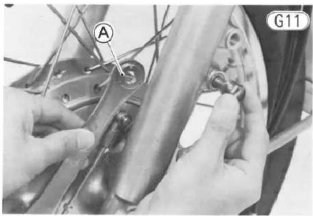
A. Welded Washer
●Install the flat washer, lockwasher, and nut on the bolt, and install the lockwasher and nut on the stud on the brake panel. Finger tighten the nuts.
- Center the brake panel assembly in the brake drum. This is done by tightening the axle lightly, spinning the wheel, and pulling the brake lever forcefully. The partially tightened axle allows the brake panel assembly to center itself within the brake drum.
NOTE: This procedure can prevent a soft, or "spongy feeling" brake.
- Holding the axle with an open end wrench so that it does not turn, tighten the axle nut to 6.5 kg·m (47 ft·lbs) of torque.
●Tighten first the front axle clamp nut and then the rear nut to 2.0 kg·m (14.5 ft·lbs) of torque. There will be a gap at the rear of the clamp after tightening.
WARNING If the clamps are installed incorrectly or improperly tightened, the clamps or the studs could fail, resulting in loss of control.

A. Arrow
C. Even Gap
B. Front
D. No Gap
●Tighten the torque link nuts to 3.3 kg-m (24 ft-lbs) of torque, and insert the torque link clips.
- Insert the speedometer inner cable into the front brake panel while turning the wheel so that the inner cable end will seat in the speedometer pinion gear.
• Install the speedometer cable retaining bolt and washer.
- Attach the brake cable, brake cable joint, and adjusting nut back onto the front brake panel. Install a new cotter pin at the end of the threaded brake cable extension.
- Slide the cable dust cover back into the groove on the brake outer cable end to secure the brake outer cable in the cable mount.

A. Dust Cover
C. Groove
B. Brake Outer Cable
- Adjust the front brake (Pg. 32).
Front Brake Disassembly (KZ440B):
WARNING Brake linings contain asbestos fiber. Inhalation of asbestos may cause serious scarring of the lungs and may promote other internal injury and illness, including cancer. Observe the following precautions when handling brake linings:
- Never blow brake lining dust with compressed air.
- If any components are to be cleaned, wash with detergent, then immediately discard the cleaning solution and wash your hands.
-
Do not grind any brake lining material unless a ventilation hood is available and properly used.
-
Remove the brake panel II from the front hub.
- Using a clean cloth around the linings to prevent grease or oil from getting on them, remove the brake shoes 14 by pulling them off the brake cam shafts.

A. Brake Shoes
- Remove the brake springs 13 (2) to separate the two brake shoes.
●Mark the position of each cam lever on the camshaft so that they can later be installed at the same angle.

A. Cam Shaft
B. Cam Lever
Front Hub (KZ440B)
G16
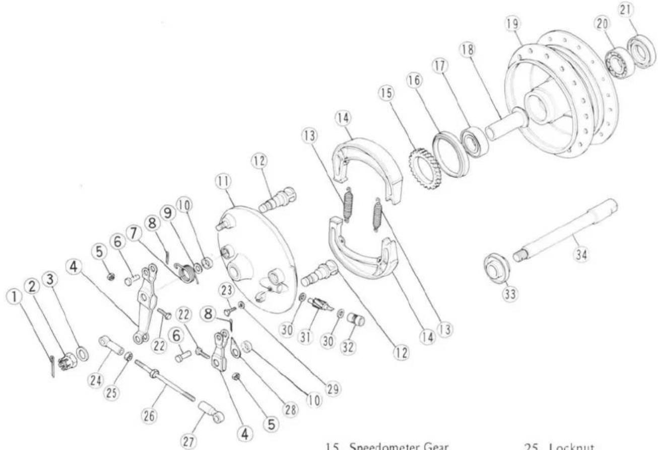
- Cotter Pin
- Axle Nut
- Washer
- Cam Lever
- Nut
- Pin
-
Return Spring
-
Cotter Pin
- Washer
- Dust Seal
- Brake Panel
- Camshaft
- Shoe Spring
-
Brake Shoe
-
Speedometer Gear
- Grease Seal
- Ball Bearing
- Distance Collar
- Front Hub
- Ball Bearing
- Grease Seal
- Bolt
- Bolt
-
Joint
-
Locknut
- Connecting Rod
- Joint
- Indicator
- Washer
- Washer
- Speedometer Pinion
- Bushing
- Cap
- Front Axle
112 DISASSEMBLY-CHASSIS
- Remove the nuts ⑤ and bolts ②2, and pull the cam levers off the camshafts.
- Remove the return spring ⑦, brake lining wear indicator 28, washer ⑨, and dust seals ⑩.
- Remove the camshafts 12.
Front Brake Assembly (KZ440B):
●Lubricate the brake parts (Pg. 203).
●Install the brake springs connecting the brake shoes.
- Wrapping a clean cloth around the linings to prevent grease or oil from getting on them, put the shoes back onto the brake panel.
●Fit the dust seals on the camshafts.
- Replace the washer and the brake lining wear indicator. The indicator should point just to the right of the "E" in RANGE.

A. Wear Indicator
B. Washer
- Install the cam levers with the return spring part of the way onto the camshafts, fit the return spring end into its hole in the panel, and put the cam levers the rest of the way into position on the camshafts. Tighten the bolts.
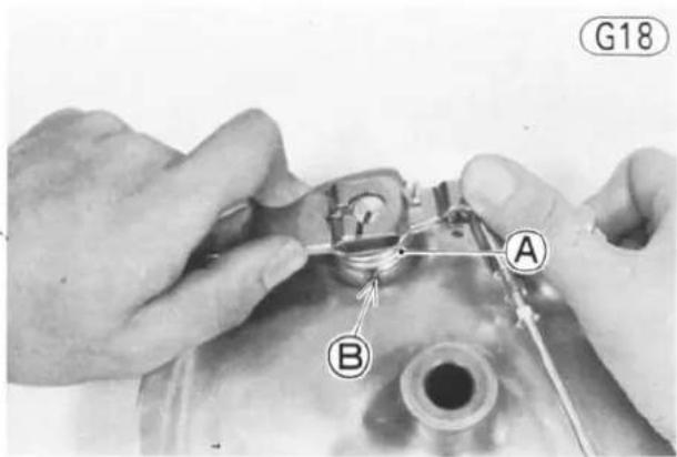
A. Return Spring
B. Hole
Speedometer Pinion Removal (KZ440B):
●Unscrew the speedometer pinion bushing 32 from the brake panel, and drop out the pinion 31 and washers 30.
Speedometer Pinion Installation (KZ440B):
- Grease the speedometer pinion, install the pinion and its washers, and screw in the speedometer pinion bushing securely.
Front Hub Disassembly (KZ440B):
- Pull the brake panel 11 and cap 33 off the front hub. - Pull off the grease seal 21 on the cap side using a hook.
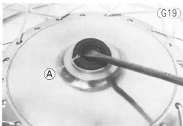
A. Grease Seal
- Insert a metal rod into the hub from the cap side, and remove the bearing 17 by tapping evenly around its inner race. The distance collar 18 will come out with the bearing.
Bearing Removal
G20
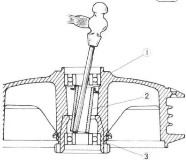
- Front Hub
- Distance Collar
-
Ball Bearing
-
Insert a metal rod into the hub from the panel side, and remove the bearing 20 on the cap side by tapping evenly around its inner race.
- To remove the grease seal 16 on the panel side, pull off the speedometer gear 15 using a gear puller, and pull off the grease seal using a hook.
Front Hub Assembly (KZ440B):
- Using a suitable tool, install the panel side grease seal and the speedometer gear. Press them in until they stop at the shoulders on the hub.
●After installing the speedometer gear, punch two points on the drum to lock the gear in place.

A. Speedometer Gear
B. Punch two points
- Inspect the bearings and replace them if necessary (Pg. 193).
●Lubricate the ball bearings (Pg. 193). - Before installing the wheel bearings, blow any dirt or foreign particles out of the hub with compressed air to prevent contamination of the bearings.
●Install the cap side ball bearing using the wheel bearing driver and the bearing driver holder (special tools). Press the bearing in until it stops at the bottom of the hole.

A. Bearing Driver Holder (57001-139)
B. Bearing Driver (57001-288)
- Install a new grease seal on the cap side using the bearing driver (special tool: P/N 57001-296) and bearing driver holder. Press the seal so that the face of the seal is level with the surface of the front hub.
●Put the distance collar into the hub.
●Install the brake panel side bearing facing the shield outward. Press the bearing in until it stops at the
bottom of the hole using the same special tools used for the other bearing installation.
FRONT DISC BRAKE (KZ440A, C, D)
Removal, installation, disassembly, and assembly of the front disc brake is divided as follows:
Pad Replacement
Caliper Removal
Caliper Installation Notes
Caliper Disassembly
Caliper Assembly
Master Cylinder Removal
Master Cylinder Installation Notes
Master Cylinder Disassembly
Master Cylinder Assembly Notes
NOTE: Disc removal and disc installation are covered in front hub disassembly and front hub assembly sections (Pgs. 108\~109).
Before working on the disc brake, take caution of the following:
CAUTION
- Except for the disc pads and disc; use only disc brake fluid, isopropyl
alcohol, or ethyl alcohol for cleaning brake parts. Do not use any other fluid for cleaning these parts. Gasoline, motor oil, or any other petroleum distillate will cause deterioration of the rubber parts. Oil spilled on any part will be difficult to wash off completely, and will eventually deteriorate the rubber used in the disc brake.
- When handling the disc pads or disc, be careful that no disc brake fluid or any oil gets on them. Clean off any fluid or oil that inadvertently gets on the pads or disc with a high flash-point solvent. Replace the pads with new ones if they cannot be cleaned satisfactorily.
- Brake fluid quickly ruins painted surfaces; any spilled fluid should be completely wiped up immediately.
- If any of the brake line fittings or the bleed valve is opened at any time, AIR MUST BE BLED FROM THE BRAKE SYSTEM (Pg. 199).
- When installing or assembling the disc brake, tighten the disc brake fittings to the values given in Table G1. Improper torque may cause the brake to malfunction.
Table G1 Disc Brake Torque
| Bleed valve | 0.85 kg·m | 74 in-lbs |
| Brake lever pivot bolt | 0.30 kg·m | 26 in-lbs |
| Brake lever pivot bolt locknut | 0.60 kg·m | 52 in-lbs |
| Caliper holder shaft nuts | 2.6 kg·m | 19.0 ft-lbs |
| *Caliper mounting bolts | 4.0 kg·m | 29 ft-lbs |
| Disc mounting bolts | 3.3 kg·m | 24 ft-lbs |
| Fitting (banjo) bolts | 3.0 kg·m | 22 ft-lbs |
| *Master cylinder clamp bolts | 0.90 kg·m | 78 in-lbs |
* : Retorque these parts regularly (Pg. 45).
114 DISASSEMBLY-CHASSIS
Pad Replacement:
- Remove the caliper mounting bolts (2).
- Lift the caliper off the disc, take out the mounting screw for pad B, and remove the pad. A lockwasher and metal plate also come off (Fig. G27).
●After pad B is removed, slide the caliper holder to the piston side and remove pad A. - Remove the bleed valve cap on the caliper, attach a clear plastic hose to the bleed valve, and run the other end of the hose into a container.
- Open (loosen) the valve slightly, push the piston in by hand as far as it will go, and then close (tighten) the valve. Wipe up any spilled fluid, and recap the bleed valve.
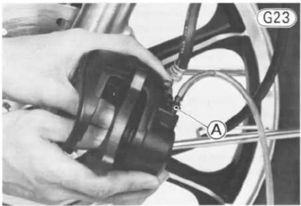
A. Bleed Valve
- Install pad A in the caliper holder so that the pad lining is toward the disc and stepped portion of the lining is toward the caliper holder shafts.

A. Stepped Portion
B. Caliper Holder Shafts
- Fit pad B, aligning the tongue on the pad with the groove in the caliper. Install the metal plate, lock-washer, and mounting screw; using a non-permanent locking agent on the screw.

A. Apply a non-permanent locking agent.
B. Fit the tongue in the groove.
●Mount the brake caliper and tighten the mounting bolts to 4.0 kg-m (29 ft-lbs) of torque.
- Since brake fluid was spilled when the bleed valve was opened, check the fluid level in the master cylinder and bleed the air from the brake system (Pg. 199).
- Check the front brake.
WARNING Do not ride the motorcycle until the pads are seated against the disc. Pump the brake lever several times until a full, firm lever "feel" is obtained. The brakes will not function on the first application of the lever if this is not done.
Caliper Removal:
- If the caliper is to be disassembled, loosen the caliper holder shaft nuts (2) before removal.
●Drain the brake fluid from the line (Pg. 198). - Remove the banjo bolt at the caliper, and temporarily secure the end of the brake hose to some high place to prevent fluid loss minimum. There is a flat washer on each side of the hose fitting.

A. Caliper Mounting Bolts
B. Banjo Bolt
C. Caliper Holder Shafts
- Remove the caliper mounting bolts (2), and take off the caliper.
Caliper Installation Notes:
- Use a new flat washer on each side of the brake hose fitting.
- Tighten the caliper holder shaft nuts (2) to the specified torque (Table G1).
- Check the fluid level in the master cylinder, and bleed the brake line (Pg. 199).

Do not ride the motorcycle until the pads are seated against the disc. Pump the
brake lever several times until a full, firm lever "feel" is obtained. The brakes will not function on the first application of the lever if this is not done.
Caliper Disassembly:
- Take out the mounting screw 7 for pad B 14 , and remove the pad. A lockwasher 6 and metal plate 15 also come off.
- Remove the pad A ⑪.
Caliper
- Remove the caliper holder shaft nuts 5 (2), and pull out the caliper holder shafts 1 (2) and the spacers 4 (2) taking care not to damage the dust covers 12 (4). Remove the caliper holder 17.
To avoid damage to the dust covers and O rings, unscrew each shaft in turn.
- Remove the dust seal 10 around the piston 9.
●Cover the caliper opening with a clean heavy cloth, and remove the piston by lightly applying compressed air to where the brake line fits into the caliper.

To avoid serious injury, never place your fingers or palm inside the caliper opening.
If you apply compressed air into the caliper, the piston may crush your hand or fingers.
NOTE: If compressed air is not available, reconnect the brake line and pump the piston out with the brake lever.
G27

- Holder Shaft
- Caliper
- Bleed Valve
- Spacer
- Nut
- Lockwasher
- Screw
- Fluid Seal
- Piston
- Dust Seal
- Pad A
- Dust Cover
- O Ring
- Pad B
- Metal Plate
- Mounting Bolt
- Caliper Holder
116 DISASSEMBLY-CHASSIS

A. Use a clean, heavy cloth.
●Taking care not to damage the cylinder surface, remove the fluid seal 8 with a hook.
Caliper Assembly:
- Clean the caliper parts with brake fluid or alcohol (See CAUTION – Pg. 113).
●Fit a new fluid seal in place inside the cylinder.
NOTE: It is recommended that the fluid seal, which is removed, be replaced with a new one. - Apply brake fluid to the outside of the piston and the fluid seal, and push the piston into the cylinder by hand. Take care that neither the cylinder nor the piston skirt get scratched.
- Install the dust seal around the dust seal stop. Check that the dust seal is properly fitted into the groove in the piston and on the dust seal stop.
Caliper Dust Seal
G29

- Apply a thin coat of PBC (Poly Butyl Cuprysil) grease to the caliper holder shafts and the holder holes. (PBC grease is a special high temperature, water-resistant grease.)
NOTE: Replace the dust covers and O rings if they are damaged. - With the caliper holder properly positioned, insert the caliper holder shafts while carefully turning the shafts to prevent damage to the dust covers.
- Install the spacers and the nuts, and tighten the nuts loosely.
NOTE: Do not forget to tighten the nuts after installing the caliper on the motorcycle.
- Install pad A in the caliper holder with its lining stepped portion facing toward the caliper holder shafts (Fig. G24).
●Fit pad B, aligning the tongue on the pad with the groove in the caliper. Install the metal plate, lock-washer, and mounting screw using a non-permanent locking agent on the screw (Fig. G25).
Master Cylinder Removal:
●Take off the right rear view mirror.
●Drain the brake fluid from the line (Pg. 198).
- Remove the front brake light switch (Pg. 133).
- Pull back the dust cover, and remove the banjo bolt to disconnect the upper brake hose from the master cylinder. There is a flat washer on each side of the hose fitting.
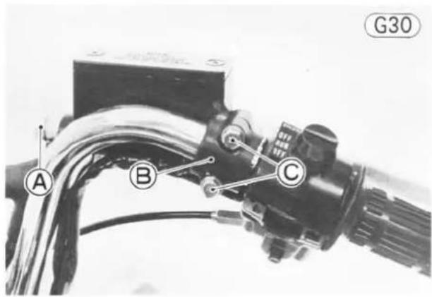
A. Banjo Bolt
B. Clamp
C. Clamp Bolts
- Remove the clamp bolts (2), and take off the master cylinder. There is a flat washer for each master cylinder clamp bolt. Immediately wipe up any brake fluid that spills.
Master Cylinder Installation Notes:
- The master cylinder clamp is installed with the small projection towards the throttle grip. Tighten the upper clamp bolt first, and then the lower clamp bolt.
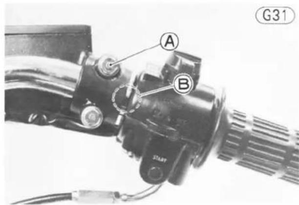
A. Tighten this bolt first.
B. Projection
- Use a new flat washer on each side of the brake hose fitting.
- Bleed the brake line after master cylinder installation (Pg. 199).
Master Cylinder Disassembly:
- Remove the screws (2), take off the master cylinder cap ⑥ and diaphragm ⑤, and empty out the brake fluid.
- Remove the locknut 10 and pivot bolt 8, and remove the brake lever 9.
- Using a thin-bladed screwdriver or some other suitable tool, press in the liner tabs which catch in the holes in the master cylinder, and then remove the liner

A. Liner
●Pull out the piston 16 and spring 15.
- Remove the spring, dust seal 18, and piston stop 17 from the piston.
Master Cylinder Assembly Notes:
- Before assembly, clean all parts including the master cylinder with brake fluid or alcohol (See CAUTION -Pg. 113). Apply brake fluid to the parts removed and to the inner wall of the cylinder.
- Be sure that the piston stop 17 is between the piston and dust seal 18.
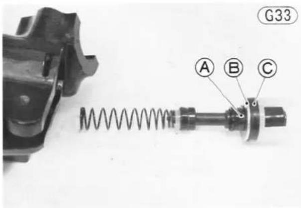
A. Piston
B. Piston Stop
C. Dust Seal
DRIVE CHAIN (KZ440A, B, C)
Removal:
- Check to see that the transmission is in neutral.
- Remove the engine sprocket cover as explained in engine sprocket cover removal (Pg. 69). The clutch cable does not require removal from the clutch release.

- Nut
- Master Cylinder Body
- Clamp
- Bolt
- Washer
- Spring
- Piston
- Piston Stop
- Dust Seal
- Liner
- Remove the clip from the drive chain master link using pliers, and remove the master link.
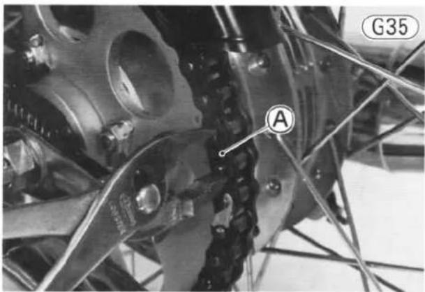
A. Clip
- Free the drive chain from the sprockets, being careful that the chain does not get dirty from contact with the ground.
Installation:
●Fit the drive chain back onto the sprockets with the ends at the rear sprocket.
- Install the master link.
- Install the master link clip with pliers. The direction of the master link clip must be as shown.
WARNING
Incorrect installation of the master link clip can allow it to catch on an adjacent
part. If the clip dislodges, the chain could come apart, and this could result in rear wheel lockup and loss of control.
Master Link Clip Installation
G36
Direction of Chain Rotation
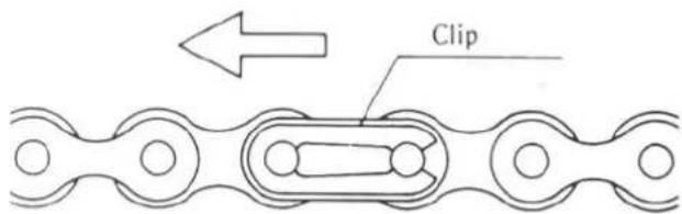
●Install the engine sprocket cover (Pg. 69).
- For the models that have the automatic side stand return mechanism, adjust its mechanism (Pg. 38).
- Adjust the drive chain (Pg. 30).
DRIVE BELT (KŽ440D)
Removal:
- Remove the rear wheel (Pg. 118).
- Remove the swing arm (Pg. 142).
-
Mark the direction of belt rotation on the belt with chalk so that the belt can be reinstalled in the same direction to ensure longer belt life.
-
Remove the engine pulley cover.
- Pull off the clutch push rod, and then take off the drive belt.

A. Push Rod
B. Drive Blet
Installation Notes:
- Be sure that the belt is installed in the same direction before removal. When installing a new belt, the white paint mark on the side of the belt should face inwards of the motorcycle.
- Tighten the pivot shaft nut to 9.0 kg-m (65 ft-lbs) of torque.
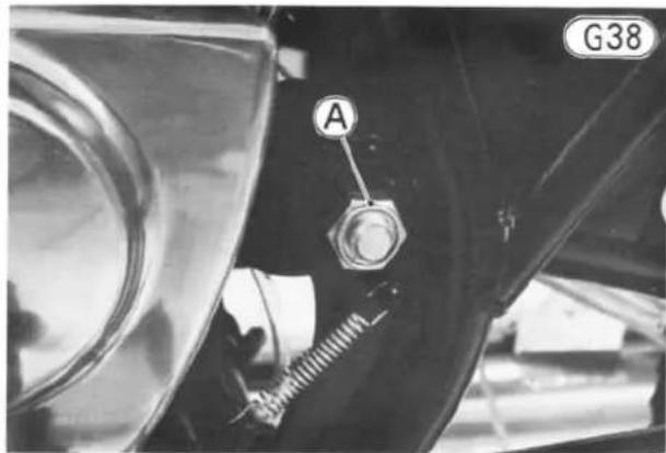
A. Pivot Shaft Nut.
- Tighten the axle nut to 7.5 kg-m (54 ft-lbs) of torque.
- Tighten the torque link nut to 3.3 kg-m (24 ft-lbs) of torque.
- Adjust the drive belt (Pg. 31).
REAR WHEEL, REAR BRAKE
Removal:
●Raise the rear wheel off the ground.
- Remove the chain (or belt) guard.
- For the chain driven models, remove the drive chain (Pg. 117).
●Take out the cotter pin, and remove the axle nut.
- For the belt driven model, loosen the left and right belt adjusting bolt locknuts.
- For belt driven model, back out both the belt adjusting bolts evenly, and push fully the wheel forward for easier wheel removal.

A. Cotter Pin
B. Axle Nut
- Remove the clip, nut, lockwasher, and bolt at the rear end of the torque link.
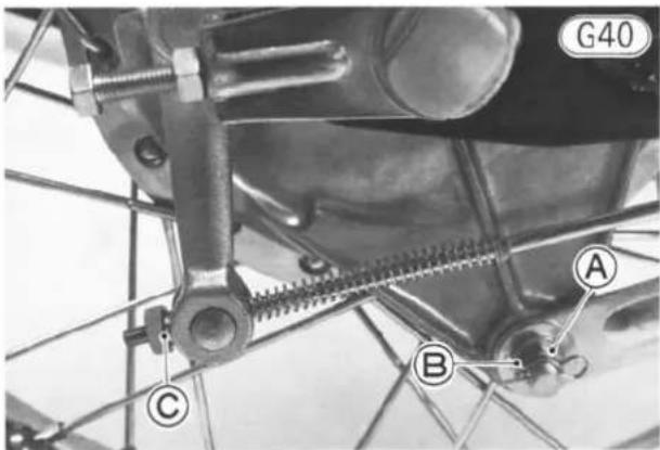
A. Torque Link Nut
B. Clip
C. Adjusting Nut
- Remove the adjusting nut from the end of the brake rod, and free the rod from the cam lever.
- Remove the spring from the brake rod and remove the brake rod joint from the brake cam lever.
- Remove the mounting bolts and lockwashers of the rear shock absorbers, lifting up on the rear wheel as necessary to avoid damaging the bolt threads.
- Slide the bottoms of the shock absorbers out of their brackets, raise the rear wheel enough to pull out the axle, and remove the axle. The chain adjusters and spacer will drop out.

- For the belt driven model, slip the drive belt off the rear pulley, and free the rear wheel from the motorcycle.
Installation:
- Apply a little grease to the inside surface of the hole in the coupling where the rear hub fits.
- Check to see that the wheel coupling, coupling collar, coupling sleeve, rubber damper, and brake panel are in place.
●Slip the rear wheel into the end of the swing arm.
- For the belt driven model, fit the belt onto the rear pulley.
- Install the chain adjuster on each side of the swing arm. The chain adjusters should be installed with the notch mark side facing out.
- Slide the axle through from right to left. Do not forget to put the spacer in place between the brake panel and the right chain adjuster.
- Attach the rear axle nut loosely.
- Install the rear shock absorber lower mounting bolts and lockwashers, and tighten them to 3.3 kg·m (24 ft·lbs) of torque.
- For the chain driven models, fit the drive chain onto the rear sprocket and install the drive chain master link and clip. The direction of the master link clip should be as shown in Fig. G36.
●Fit the brake rod joint to the cam lever.
●Install the spring on the end of the brake rod, fit the rod through the joint, and screw on the adjusting nut.
- Insert the torque link bolt into the brake panel, and install the torque link, lockwasher, and nut finger tight.
- Adjust the drive chain (Pg. 30) or belt (Pg. 31).
-Adjust the rear brake (Pg. 34).
- Check the rear brake light switch and adjust if necessary (Pg. 35).
Rear Brake Disassembly:
WARNING
Brake linings contain asbestos fiber. Inhalation of asbestos may cause serious scarring of the lungs and may promote other internal injury and illness, including cancer. Observe the following precautions when handling brake linings:
- Never blow brake lining dust with compressed air.
-
If any components are to be cleaned, wash with detergent, then immediately discard the cleaning solution and wash your hands.
-
Do not grind any brake lining material unless a ventilation hood is available and properly used.
- Remove the brake panel 18 from the wheel.
- Using a clean cloth around the linings to prevent grease or oil from getting on them, remove the brake shoes 15, by pulling up on the center of the linings.
Rear Hub
G42

- Cotter Pin
- Axle Nut
- Rear Sprocket (or Pulley)
- Collar
- Grease Seal
- Circlip
-
Ball Bearing
-
Coupling
- Sleeve
- Rubber Damper
- Distance Collar
- Rear Hub
- Nut
- Double Washer
-
Brake Shoe
-
Spring
- Sprocket (or Pulley) Mounting Bolt
- Brake Panel
- Dust Seal
- Indicator
- Ball Bearing
-
O Ring
-
Ball Bearing
- Circlip
- Spacer
- Brake Camshaft
- Rear Axle
- Cam Lever
- Washer
- Bolt

A. Brake Shoe
B. Spring
- Remove the springs 16 (2) to separate the two brake shoes.
- Mark the position of the cam lever 28 so that it can be installed later in the same position.
- Unbolt and remove the cam lever, brake lining wear indicator 20, dust seal 19, and camshaft 26.
Rear Brake Assembly:
●Lubricate the brake parts (Pg. 203).
●Put the camshaft back into the panel.
●Fit the springs onto the brake shoes, and wrapping a clean cloth around the linings to prevent grease or oil from getting on them, install the shoes on the brake panel.
- Fit the dust seal and the indicator on the serration so that it points to the extreme right of the USABLE RANGE.
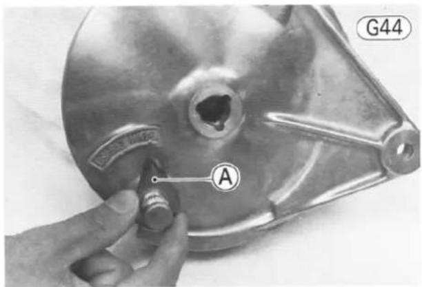
A. Indicator
- Install the cam lever in its original position on the camshaft, and tighten its bolt.
Wheel Coupling Disassembly:
●Straighten the bent portions of the double washers (2).
- Remove the rear sprocket (or pulley) nuts 13 (4) and double washers to separate the rear sprocket (or pulley) ③ and wheel coupling 8.

A. Double Washer
B. Sprocket Nut
- Remove the coupling and rubber damper 10 from the wheel.
●Pull out the coupling collar ④ from the left, and the coupling sleeve ⑨ from the right.
●Using a hook, pull off the grease seal ⑤.

A. Grease Seal
- Remove the circlip 6.
- Remove the bearing 7 by tapping from the wheel side evenly around the bearing inner race.

A. Rod
B. Bearing Inner Race
Wheel Coupling Assembly:
- Inspect the bearing, and replace if necessary (Pg. 193).
- Lubricate it (Pg. 193), and install it using the bearing driver and the bearing driver holder (special tools). Drive the bearing in until it stops at the bottom of the hole.
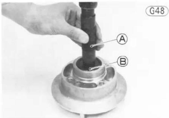
A. Bearing Driver Holder (57001-139)
B. Bearing Driver (57001-289)
122 DISASSEMBLY-CHASSIS
●Install the circlip.
- Replace the grease seal with a new one using the bearing driver (special tool: P/N 57001-296) and bearing driver holder. Drive in the seal until the face of the seal is level with the end of the grease seal hole.
- Install the rear sprocket (or pulley), new double washers (2), and nuts (4), and install the nuts finger tight.
WARNING
The rear sprocket (or pulley) must be installed with the chamfered hole side
facing toward the coupling. If not, the sprocket (or pulley) will not seat on the coupling evenly, causing the drive chain (or belt) to be thrown off by excessive sprocket (or pulley) runout during operation. This can result in rear wheel lockup and loss of control.

A. Chamfer
- Inspect the O ring 22 on the rear hub, replace it with a new one if it has deteriorated, and apply a little grease to the O ring.
●Install the coupling sleeve on the right side and the coupling collar on the left side of the coupling. - Install the rubber damper and wheel coupling on the rear hub, and then tighten the sprocket (or pulley) nuts to 3.3 kg-m (24 ft-lbs) of torque.
●Bend the tab portions of the double washers over the nuts.

A. Bend the tab portions
Rear Hub Disassembly:
- Remove the wheel coupling 8, rear brake panel 18, and rubber damper 10 from the wheel.
- Remove the circlip 24.
- Insert a metal rod into the hub from the brake panel side, and remove the left side bearing 21 by tapping evenly around the bearing inner race. The distance collar 11 will come out with the bearing.
Bearing Removal
G51
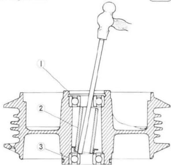
- Rear Hub
-
Distance Collar
-
Ball Bearing
- Insert the metal rod into the hub from the other side, and tap out the remaining bearing 23.
Rear Hub Assembly:
- Inspect the bearings and replace them if necessary (Pg. 193).
●Lubricate the ball bearings (Pg. 193).
●Before installing the wheel bearings, blow any dirt or foreign particles out of the hub with compressed air to prevent contamination of the bearings.
●Install the coupling side ball bearing using the wheel bearing driver and the bearing driver holder (special tools). Press the bearing in until it stops at the bottom of the hole.

A. Bearing Driver Holder (57001-139)
B. Bearing Driver (57001-290)
●Put the distance collar into the hub.
- Install the brake panel side bearing facing the shield outward. Press the bearing in until it stops at the bottom of the hole using the same special tools used for the other bearing installation.
- Install the circlip.
- Inspect the O ring 22 on the rear hub and replace it if necessary. Apply a little grease to the O ring before fitting the coupling on the rear hub.
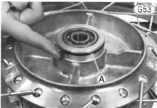
A. "O" Ring
- Step on the side of the tire opposite the valve stem, and start prying the tire off the rim near the valve stem with tire irons. Take care not to insert the tire irons so deeply that the tube gets damaged (Fig. G55). For cast wheel models, use the rim protector (special tool, P/N: 57001-1063) not to damage the rim.

A. Tire Irons
- Remove the tube when one side of the tire is pried off.
●Pry the tire off the rim.
TIRE, TUBE
Removal:
- Remove the wheel from the motorcycle (Pg. 107, 109, or 118).
Do not lay the wheel on the ground with the disc facing down. This could damage sc. - Mark the valve stem position on the tire with chalk so that the tire may be reinstalled in the same position to maintain wheel balance.
●Take out the valve core to let out the air. - Remove the valve stem nut.
CAUTION
or warp the disc.

A. Valve Stem Nut
- Use a rubber mallet to break the tire beads away from both sides of the rim.
Installation:
- Put just enough air in the tube to keep it from getting caught between the tire and rim. To much air makes fitting difficult, and too little will make the tube more liable to be pinched by the irons. Dust the tube and the inside of the tire with talcum powder, and insert the tube into the tire, even if the tire was completely removed from the rim. Insert the valve stem into the rim, and screw the nut on loosely.
- Lubricate the tire beads and rim flanges with a soap and water solution or liquid soap to help seat the tire beads in the rim while inflating the tire.
- If the tire has an arrow molded into the side wall to show the direction of tire rotation, be sure that the tire does not go on backwards.
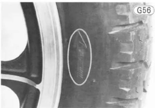
- If the tire was completely removed, pry one side of the tire back onto the rim.
NOTE: If a new tire is installed, the yellow paint mark on the tire should be aligned with the valve stem for best balancing results.

A. Yellow Paint Mark
B. Valve Stem
●Pry the other side of the tire onto the rim, starting at the side opposite the valve. Take care not to insert the tire irons so deeply that the tube gets damaged.
- Check that the tube is not pinched between the tire and rim, and then inflate to the specified pressure (Pg. 191).
●Tighten the valve stem nut, and put on the valve cap.
●Balance the wheel (Pg. 36).
●Mount the wheel on the motorcycle (Pg. 107, 110, or 119).
- Adjust the drive chain (Pg. 30), and rear brake (Pg. 34), if the rear wheel was removed.
- Check the front brake.
RIM (KZ440B)
Removal:
- Remove the wheel from the motorcycle (Pg. 107, 109, or 118).
- Remove the rubber band.
●Take the tire and tube off the rim. - Tape or wire all the spoke intersections so that the spokes don't get mixed up, and unscrew the nipples from all the spokes with a screwdriver.

A. Nipple
Installation:
●Fit all the spokes through the holes, and screw all the nipples onto the spokes tightening them partially.
- Suspend the wheel by the axle, and set up a dial gauge to measure rim runout. Fix the axle in place if necessary to prevent horizontal movement.


A. Axial Runout Measurement
B. Radial Runout Measurement
●Tighten the spokes evenly so that the radial (out from the axle) runout is less than 0.8 mm and the axial (side to side) runout is less than 0.5 mm.
●Make sure that the spokes are tightened evenly. Standard torque is 0.3 kg·m (26 in-lbs).
●Mount the tube and tire (Pg. 123).
●Balance the wheel (Pg. 36).
●Mount the wheel on the motorcycle (Pg. 107, 110, or 119).
- Adjust the drive chain (Pg. 30) and rear brake (Pg. 34), if the rear wheel was removed.
- Check the front brake (Pg. 32) (KZ440-B).
SPOKE (KZ440B)
Breakage Replacement:
- Reduce the tire air pressure by a small amount.
- Insert the new spoke through the hub, and bend it to meet the nipple.
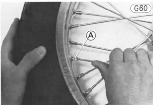
A. Nipple
●Tighten with a spoke wrench. Standard torque is 0.3 kg·m (26 in-lbs).
●Inflate the tire to standard pressure (Pg. 191).
FRONT BRAKE CABLE (KZ440B)
Removal:
- Slide the cable dust cover out of its position on the outer cable end.
●Screw off the adjusting nut, and free the brake cable from the brake panel. Also remove the brake cable joint.

A. Brake Cable
C. Adjusting Nut
B. Cable Joint
- Loosen the knurled locknut on the front brake lever, and line up the slots on the brake lever, knurled locknut, and adjuster, and free the front brake cable from the brake lever.

A. Knurled Locknut
C. Brake Cable
B. Adjuster
- Slide the cable out of the guides and free the cable from the motorcycle.
Installation:
●Before installing the brake cable, lubricate it (Pg. 38).
- Run the cable through the guides on the steering stem base and front fender. Route the cable with a minimum of bending so that the inner cable will slide smoothly.
- Connect the upper end of the cable back into the brake lever and through the slots on the brake lever, knurled locknut, and adjuster.
- Attach the brake cable, brake cable joint, and adjusting nut back onto the front brake panel. Use a new cotter pin at the end of the threaded brake cable extension.
- Slide the cable dust cover back into the groove on the brake outer cable end to secure the brake outer cable in the cable mount.

A. Cable Dust Cover
C. Outer Cable
B. Groove
-Adjust the front brake (Pg. 32).
CLUTCH CABLE
Removal:
- Remove the engine sprocket (or pulley) cover (Pg. 69).
- Remove the clutch cable clamp or strap that holds the clutch cable to the frame down tube.
- Loosen the knurled locknut on the clutch lever holder, and screw in the adjuster.
●Line up the slots in the clutch lever, locknut, and adjuster and then free the cable from the lever.

A. Outer Cable
C. Knurled Locknut
B. Adjuster
●Pull the cable free of the motorcycle.
Installation:
●Before installing the clutch cable, lubricate it (Pg. 38).
- Run the upper end of the cable through the cable guide (where provided), between the meter bracket and the stem head, and to the clutch lever.
●Fit the tip of the cable back into the clutch lever.
- Run the lower end of the clutch cable between the left down tube and the lower part of the engine.
• Install the engine sprocket (or pulley) cover (Pg. 69).
-Adjust the clutch (Pg. 25).
- For the models that have the automatic side stand return mechanism, adjust its mechanism (Pg. 38).
THROTTLE CABLE (one throttle cable model) Removal:
- Remove the fuel tank (Pg. 50).
- Remove the strap that hold the throttle cable to the frame top tube.
- Loosen the throttle cable adjuster locknut, turn the cable adjuster out of its bracket, and slip the tip of its inner cable out of the pulley.
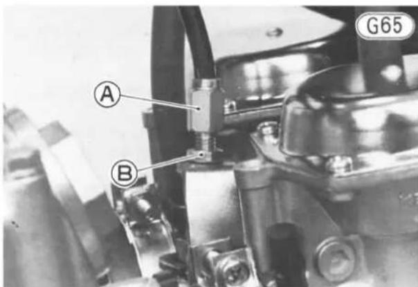
A. Cable Adjuster
B. Locknut
- Loosen the cable elbow nut, and pull the cable out between the right front fork leg and the head pipe.
- Remove the right switch housing screws (2), and open the housing.
- Slip the throttle cable tip from its catch in the throttle grip.
●Unscrew the throttle cable elbow, and pull the cable out of the right switch housing.

A. Cable Elbow
Installation:
●Before installing the throttle cable, lubricate it (Pg. 38).
●Screw the throttle cable elbow into the hole in the right switch housing. Screw it in almost all the way, and then lightly tighten the elbow nut.
- Run the cable between the right front fork leg and the head pipe, and to the carburetors. The cable should be naturally routed.
●Turn the throttle grip so that the cable catch is facing up, and fit the cable tip into the catch.
- Put together the right switch housing, and tighten its screws. The upper half of the housing has a small projection which fits into a small hole in the handlebar. The front switch housing screw is longer than the rear screw.
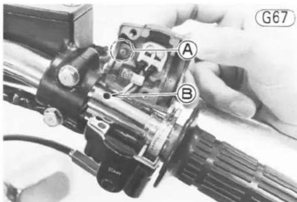
A. Projection
B. Hole
●Fit the tip of the cable into the catch in the pulley, and screw its adjuster down into the bracket.
- Center the adjuster in its place in the bracket, and then tighten the locknut.
- Turn the elbow in the direction of its cable, and tighten its elbow nut to secure the elbow in the proper position.
●Tighten the strap that hold the throttle cable to the frame top tube.
●Install the fuel tank (Pg. 50).
-Adjust the throttle cable (Pg. 21).
THROTTLE CABLES
(two throttle cables model)
Removal:
- Remove the fuel tank (Pg. 50).
- Remove the strap that hold the throttle cables to the frame top tube.
- Loosen the locknuts, and screw in the adjusting nuts at the upper end of the throttle cables all the way to give the cables plenty of play.
CAUTION Removing the throttle cables from the carburetors without enough cable play, may cause throttle cable damage.
- Loosen the throttle cable adjuster locknuts (2), and screw down the decelerator cable adjuster fully into the cable bracket.
- Screw the accelerator cable adjuster out of its bracket, slip the tip of its inner cable out of the pulley, and then do the same with the other throttle cable.

A. Decelerator Cable Adjuster
B. Locknut
C. Accelerator Cable Adjuster
- Loosen both cable elbow nuts, and pull the cables out between the right front fork leg and the head pipe.
- Remove the right switch housing screws (2), and open the housing.
- Slip both throttle cable tips from their catches in the throttle grip.
- Unscrew the decelerator throttle cable elbow, and pull the cable out of the right switch housing. Then do the same with the accelerator throttle cable elbow to free the throttle cables from the motorcycle.

A. Accelerator Cable Elbow
B. Decelerator Cable Elbow
Installation:
●Before installing the throttle cables, lubricate them (Pg. 38).
- Screw the accelerator throttle cable elbow (shorter than the decelerator throttle cable elbow) into the front hole in the right switch housing. Screw it in almost all the way, and then lightly tighten the elbow nut.
- Screw in the decelerator cable elbow almost all the way, and then lightly tighten the elbow nut.
- Run both cables between the right front fork leg and the head pipe, and to the carburetors. The cables should be naturally routed, neither one twisted about the other.
- Turn the throttle grip so that the cable catches are facing up, fit the accelerator throttle cable tip into the front catch and the other cable tip into the rear catch.
- Put together the right switch housing, and tighten its screws. The upper half of the housing has a small projection which fits into a small hole in the handlebar. The front switch housing screw is longer than the rear screw (Fig. H67).
●Fit the tip of the decelerator throttle cable into the rear catch in the pulley, and screw its adjuster down into the bracket all the way.
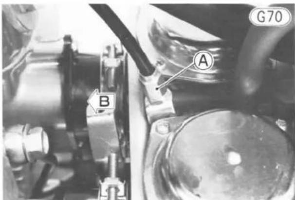
A. Decelerator Throttle Cable
B. Front
●Fit the tip of the other cable into the other catch, and lift its adjuster onto the bracket while turning the throttle grip at the same time, if necessary.
- Center each adjuster in its place in the bracket, and then tighten the locknuts.
- Turn each elbow in the direction of its cable, and tighten its elbow nut to secure the elbow in the proper position.
●Tighten the strap that hold the throttle cables and wiring harness to the frame.
• Install the fuel tank (Pg. 50).
-Adjust the throttle cables (Pg. 21).
SPEEDOMETER CABLE
Removal:
- Disconnect the upper end of the speedometer cable with pliers.
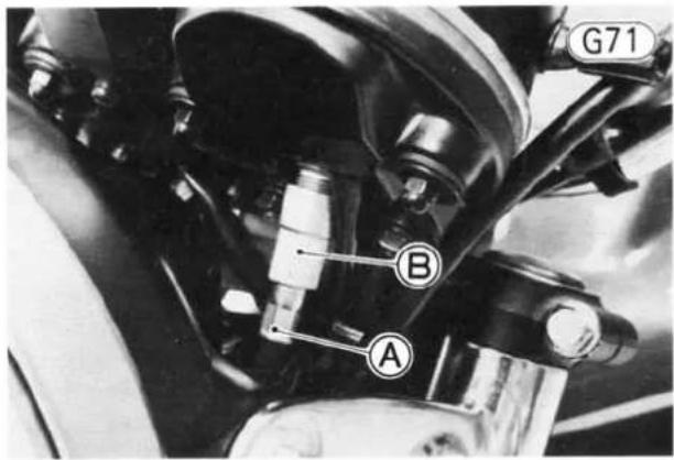
A. Speedometer Cable
B. Unscrew with pliers.
- Disconnect the lower end of the speedometer cable as follows. Disc brake type: Disconnect the lower end of the speedometer cable with pliers.
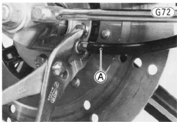
A. Speedometer Cable
Drum brake type: Remove the speedometer cable bolt and washer, and pull the lower end of the speedometer cable off the brake panel.
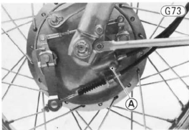
A. Speedometer Cable Bolt
●Pull the cable free.
Installation:
●Before installing the speedometer cable, lubricate it (Pg. 40).
- Run the speedometer cable through its guides at the stem base and the front fender left side, and secure the upper end of the cable to the speedometer with pliers.
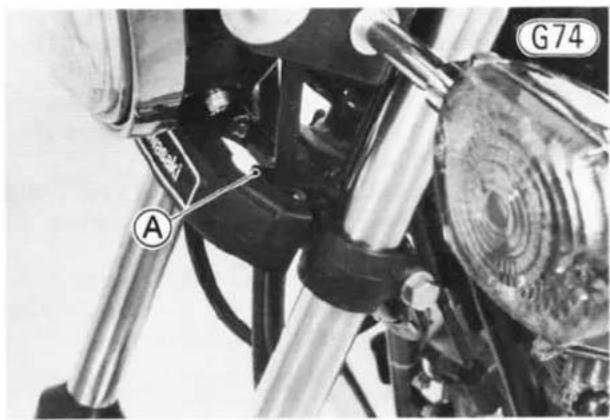
A. Cable Guide
●Install the lower end of the speedometer cable as follows.
Disc brake type: Insert the speedometer inner cable into the speedometer gear housing while turning the wheel so that the slot in the end of the cable will seat in the tongue of the speedometer pinion. Tighten the cable nut with pliers.
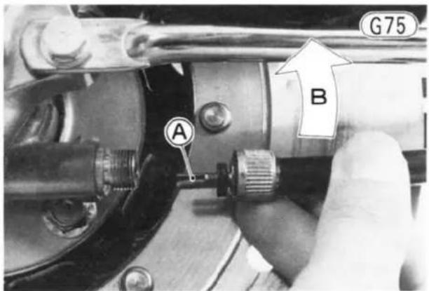
A. Slot
B. Turn the wheel.
Drum brake type: Insert the speedometer inner cable into the front brake panel while turning the wheel so that the inner cable end will seat in the speedometer pinion gear. Install the speedometer cable bolt and washer.
TACHOMETER CABLE
Removal:
- Disconnect the upper and lower ends of the tachometer cable with pliers.
●Free the cable from the motorcycle.
Installation:
●Before installing the tachometer cable, lubricate it (Pg. 40).
- Run the tachometer cable through its guide at the stem base fit the inner cable into the tachometer, and tighten the cable nut with pliers.
●Fit the bottom end of the cable into its place in the cylinder head. Turn it if necessary so that it fits all the way into place, and tighten its nut with pliers. There is a gasket between the outer cable and the tachometer pinion holder.

A. Headlight Rim
HEADLIGHT UNIT
Removal:
- Take out the retaining screws 19, lockwashers 18, and collars 17 (2 ea).
-
Pull the bottom of the headlight unit ① out of its housing ⑫, and then push down on the top of the headlight rim ② to free the unit from the housing.
-
Disconnect the headlight socket ⑪ from the rear of the unit.
- Remove the pivot screws ③, nuts ⑨, and rubber dampers ⑧ (2 ea).
- Remove the beam horizontal adjusting screw ④, and separate the sealed beam unit from the rim ②. A nut ⑩, spring seat ⑥, and spring ⑤ come off with the adjusting screw.
Headlight Unit
G77

- Nuts
-
Nut
-
Lockwasher
- Retaining Screws
Installation Notes:
- The spring seat on the adjusting screw goes between the spring and the bracket.
- The top of the sealed beam unit is marked "TOP".

A. Top Mark
- Carry out the headlight adjustment after installation (Pg. 37).
TURN SIGNAL LIGHT
Bulb Replacement:
- Remove the lens mounting screws, and take off the lens.
- Press the bulb inwards, and holding the bulb in this position, twist it to the left and pull it out.

A. Bulb
●Install a new 12 volt bulb of the correct wattage (see the wiring diagram).
- Fit the rubber gasket in place, and install the lens. Be careful not to overtighten the mounting screws.
INDICATOR LIGHTS
(Neutral, Oil, High Beam, Turn)
Removal:
- Remove the screws (2) and take off the upper cover.

A. Upper Cover
B. Screws
●To remove the indicator lights, first press the bulb inwards, then holding the bulb in this position, twist it to the left and pull it out.
Installation Note:
- Use 12V 3.4W bulbs for indicator light replacement.
TURN SIGNAL ASSEMBLY
Removal (front, either side):
- Open the headlight housing, and free the headlight unit from the motorcycle (Pg. 129).
- Disconnect the turn signal/running position light leads in the headlight housing.
- Remove the mounting nut, lockwasher, flat washer, and black/yellow ground lead terminal, and pull the front turn signal from the front fork cover stay.

A. Ground Lead Terminal
C. Lockwasher
B. Flat Washer
D. Nut
G83

Installation Notes (front, either side):
- If the front turn signal dampers have been removed, install them as shown in Fig. G83.
- Adjust the headlight (Pg. 37).
Removal (rear, either side):
- Unlock the seat and swing it open.
- For the KZ440-C, remove the license plate, and then remove the bolts, lockwashers, and flat washers (2 ea), and remove the rear fender cover toward the front.

A. Bolts
B. Rear Fender Cover
C. Flat Washers
●Disconnect the gray turn signal lead.
- Remove the mounting bolt, nut, lockwasher, and flat washers (2), and pull the rear turn signal assembly off the stay.
Installation Notes (rear, either side):
- Check that the black/yellow lead is grounded in the license plate bracket.
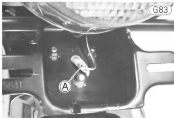
A. Ground Lead
- Connect the turn signal leads according to the Wiring Diagram.
SPEEDOMETER, METER LIGHT
Removal:
- Disconnect the upper end of the speedometer cable with pliers.
132 DISASSEMBLY-CHASSIS

A. Cap Nuts
B. Cable
- Remove the cap nuts, flat washers, dampers (2 ea) from the bottom of the meter holder.
●Pull up the speedometer, pull the meter light out of the speedometer base, and remove the speedometer.
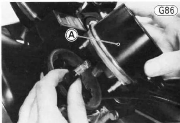
A. Speedometer
- To remove the meter light bulb, first press the bulb inward, then holding the bulb in this position, twist it to the left and pull it out.
Place the meter so that the correct side of the meter is up. If a meter is left
upside down or sideways for any length of time it will malfunction.
Installation Note:
- Use 12V 3.4W bulb for meter light replacement.
TACHOMETER, METER LIGHT, INDICATOR LIGHTS (Stop, High Beam)
Removal:
- Disconnect the upper end of tachometer cable with pliers.
- Remove the cap nuts, flat washers, dampers (2 ea) from the bottom of the meter holder.
●Pull up the tachometer, and pull the meter light and indicator lights (2) out of the tachometer base, and remove the tachometer.
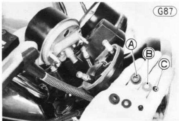
A. Rubber Damper
C. Cap Nut
B. Flat Washer
- To remove the meter and indicator bulbs, first press the bulb inwards then holding the bulb in this position, twist it to the left and pull it out.

Place the meter so that the correct side of the meter is up. If a meter is left
upside down or sideways for any length of time it will malfunction.
Installation Notes:
- Use 12V 3.4W bulb for meter and indicator lights replacement.
- Refer to the Wiring Diagram for light location by lead color.
TAIL/BRAKE LIGHT
Bulb Replacement:
- Remove the lens mounting screws, and take off the lens.
- Press the bulb inwards, and holding the bulb in this position, twist it to the left and pull it out.

A. Bulb
- Replace a burned-out bulb with a new 12 volt bulb of the correct wattage (see the wiring diagram).
- Fit the rubber gasket in place, if removed, and install the lens. Be careful not to overtighten the mounting screws.
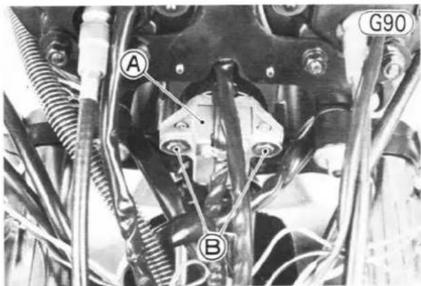
A. Ignition Switch
B. Mounting Bolts
Installation:
- Fit the ignition switch and steering lock assembly in place, and tighten the bolts (2). The sequence is bolt, lockwasher, flatwasher, rubber damper, steering lock assembly, rubber damper, and collar.
- Connect the ignition switch wiring harness socket to its plug in the headlight housing.
●Mount the headlight housing in place tightening its mounting bolts. The sequence is mounting bolt, flat washer, fork cover, housing collar, and nut.
●Install the headlight unit (Pg. 130).
-Adjust the headlight (Pg. 37).
IGNITION SWITCH
Removal:
- Open the headlight housing, and free the headlight unit from the motorcycle (Pg. 129).
- Disconnect the ignition switch wiring harness socket from the plug (4-pin) it connects to in the headlight housing and push the socket out of the housing.
- Remove the headlight housing mounting bolts (2). Each bolt has a nut, collar, and washer.
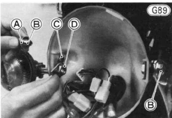
A. Flat Washer
C. Collar
B. Mounting Bolt
D. Nut
- Move the headlight housing down slightly.
- Remove the bolts (2) from the bottom of the steering lock assembly, and remove the steering lock assembly and ignition switch. Each bolt has a lockwasher, flatwasher, collar, and two rubber dampers.
FRONT BRAKE LIGHT SWITCH
Removal:
- Open the headlight housing, and free the headlight unit from the motorcycle (Pg. 129).
- Disconnect the brown and the blue front brake switch lead connections in the headlight housing, and pull these leads out of the housing.
- Remove the straps (2) on the right side of the handlebar, and free the front brake switch leads.
- Using a thin-bladed screwdriver or some other suitable tool, press in the front brake switch tab which catches in the hole in the underside of the brake lever holder, and then remove the switch.

A. Brake Light Switch
134 DISASSEMBLY-CHASSIS
Installation Note:
- Check the brake light switch operation after installation.
REAR BRAKE LIGHT SWITCH
Removal:
- Remove the rear brake light switch spring.
●Unfasten the strap which holds the switch leads on the frame. - Disconnect the blue and brown leads from the rear brake light switch under the fuel tank.

A. Switch Leads
- Press in the rear brake light switch tabs which catch in the bracket hole, and remove the rear brake light switch.
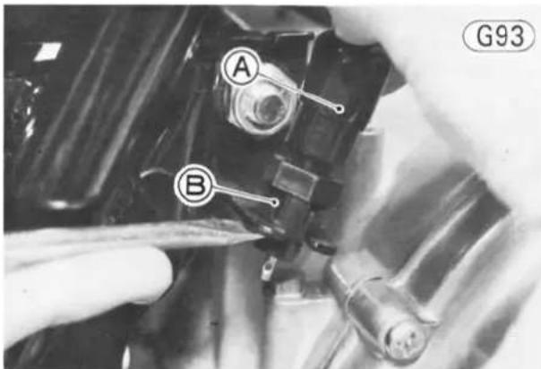
A. Brake Light Switch
B. Tab
Installation Note:
-Adjust the switch after installation (Pg. 35).
HANDLEBAR
Removal:
●Take off the rear view mirrors.
- Remove the fuel tank (Pg. 50) or cover it with a thick cloth to avoid damaging the painted surface.
- Loosen the locknut, and turn in fully the adjuster at the center of the clutch cable to give the cable plenty of play.
- Remove the clutch adjusting cover.
- Loosen the locknut, and turn in the clutch adjusting screw a couple of turns to give the clutch cable plenty of play.

A. Adjusting Screw
B. Locknut
- Loosen the knurled locknut on the clutch lever, and turn in the adjuster and line up the slots in the clutch lever, locknut, and adjuster. Free the inner cable from the lever.

A. Clutch Cable
C. Knurled Locknut
B. Adjuster
-
Remove the straps which hold the left switch wiring harness and right switch wiring harness to the handle-bar.
●Take out the left switch housing screws (2), and remove the housing from the handlebar. If necessary, loosen the clutch lever holder bolt, and slide the clutch lever to the right. -
Remove the right switch housing screws (2), and open up the housing.
- For the front disc-brake model, loosen the master cylinder clamp bolts (2).
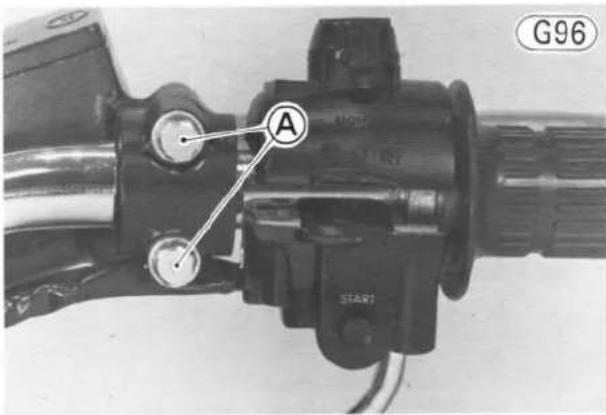
A. Clamp Bolts
- For the front drum-brake model, loosen the front brake lever holder bolt.
- Remove the handlebar clamp bolts and lockwashers (4 ea), remove the clamps (2), and slide the handlebar from the throttle grip, right switch housing, and master cylinder or front brake lever holder.

A. Clamp Bolts
B. Clamps
- To remove the clutch lever, loosen the clutch lever holder bolt, cut off the left handlegrip, which is bonded to the handlebar, and slide off the clutch lever.
Installation Notes:
- The standard angle of the handlebar mounting position is as follows. But it is preferable to set the handlebar to suit owner's preference.
For the chopper type handlebar, mount it so that the angle of it rises about 10° from the angle of the front fork as shown.

A. 10 °
For the standard type handlebar, mount it so that the angle of it matches the angle of the front fork. Tighten the handlebar clamp bolts evenly to 2.1 kg·m (15.0 ft-lbs) of torque.
- Put together the right switch housing, and tighten its screws. The upper half of the housing has a small projection which fits into a small hole in the handlebar (Fig. G67).
- For the front disc-brake model, the brake lever mounted at the proper angle, tighten first the upper and then lower master cylinder clamp bolt to 0.90 kg·m (78 in-lbs) of torque.
- Check and adjust the following items.
○Front Brake
○Throttle Cable (Pg. 21).
○Clutch (Pg. 25).
○Rear View Mirrors
STEERING STEM
Removal:
- Remove the fuel tank (Pg. 50).
- Remove the speedometer cable (Pg. 127).
- Remove the front brake cable (Pg. 125).
- Remove the front wheel (Pg. 107 for a disc-brake model or Pg. 109 for the drum-brake model).
-
Remove the headlight unit (Pg. 129).
-
Disconnect all the leads and plugs in the headlight housing.
- Remove the headlight housing mounting bolts (2) and remove the headlight housing. Each bolt has a flat washer, collar, and nut.

A. Headlight Housing
B. Mounting Bolts
C. Stem Base Cover
- Remove the screws (2), and take off the stem base cover (if provided).
●Unscrew the bolts, and remove the speedometer and tachometer cable guide(s).

A. Cable Guide
B. Mounting Bolts
- For the front disc-brake model, remove the clamp bolts (2), and take off the master cylinder. There is a flat washer for each master cylinder clamp bolt.
- Remove the caliper mounting bolts, lockwashers, and flat washers (2 ea), and remove the caliper together with the master cylinder and brake hose.

A. Mounting Bolts
B. Brake Hose
C. Caliper
- Disconnect the tachometer cable at the tachometer with pliers.
- Loosen the locknut, and turn in fully the adjuster at the center of the clutch cable to give the cable plenty of play.
- Remove the clutch adjusting cover.
- Loosen the locknut, and turn in the clutch adjusting screw a couple of turns to give the clutch cable plenty of play.

A. Adjusting Screw
B. Locknut
- Loosen the knurled locknut on the clutch lever holder, and screw in the adjuster, lining up the slots in the clutch lever, knurled locknut, and adjuster. Free the inner cable from the lever.
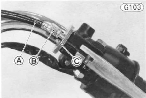
A. Clutch Cable B. Adjuster
C. Knurled Locknut
- Remove the straps which hold the right switch wiring harness to the handlebar.
- Remove the strap which secures the wiring harness to the frame top tube.
- Disconnect all the leads and plugs from the left and right switch housings under the frame top tube.
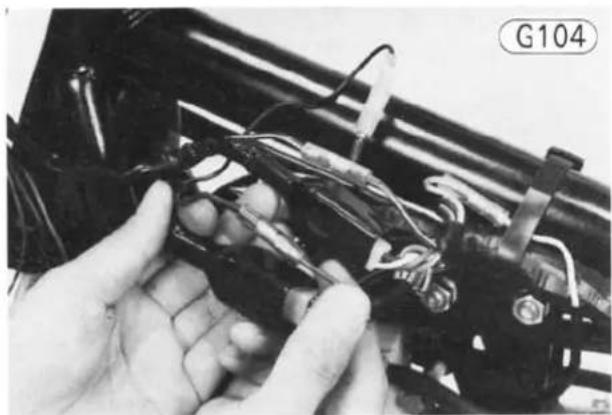
- Pull the right switch wiring harness out through the space between the stem head and the instrument unit.
- Remove the right switch housing screws (2), and open the housing.
- Loosen the front fork upper clamp bolts (2).
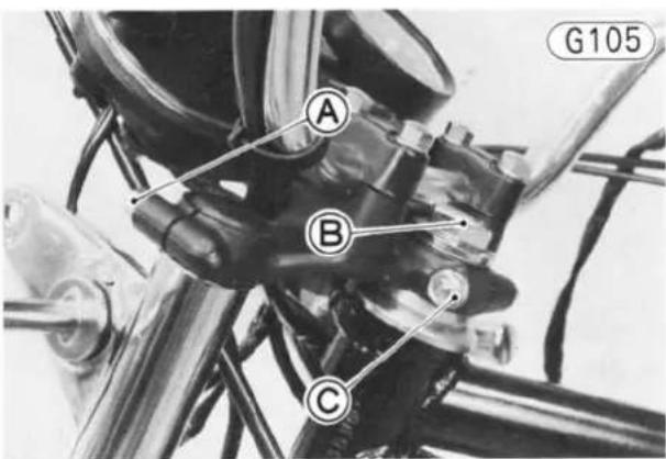
A. Fork Upper Clamp Bolt
B. Stem Head Bolt
C. Head Clamp Bolt
- Loosen the stem head clamp bolt, and then remove the stem head bolt, lockwasher, and flat washer.
- Tap lightly on the bottom of the stem head with a mallet, and then remove the steering stem head together with the handlebar, meters, and ignition switch. Slide the handlebar from the throttle grip and the right switch housing.
CAUTION Place the stem head so that the correct side of the meter is up. If a meter is left upside down or sideways for any length of time, it will malfunction.

A. Stem Head
B. Fork Cover
- Remove the turn signals. For the fork cover type model, take off a stem base cover, damper ring, and rubber damper at the bottom.
- Loosen the front fork lower clamp bolts (2), and pull out both fork legs and front fender at a time with a twisting motion.
- Push up on the stem base, and remove the steering stem locknut with the stem nut wrench (special tool); then remove the steering stem and stem base (single unit). As the stem is removed, some of the steel balls will drop out of the lower outer race. Remove the rest. There are 19 steel balls in the lower outer race.
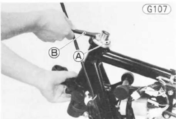
A. Stem Locknut
B. Stem Nut Wrench (57001-134)
- Remove the steering stem cap, the upper inner race, and the upper steel balls (19).
Installation Notes:
- Apply grease to the upper and lower outer races in the head pipe so that the steel balls will stick in place during stem insertion. Install the upper steel balls (19) and lower steel balls (19). All upper and lower steel balls are one size.

A. Steel Balls
- Put on the upper inner race and steering stem cap. Insert the steering stem into the head pipe, and finger tighten the steering stem locknut.
- For the fork cover type model, install the rubber damper ring, base cover, and fork cover, on each tube in this order.

A. Rubber Damper
C. Base Cover
B. Damper Ring
- Install the front fork referring to the front fork "Installation Notes" (Pg. 139).
- Tighten the stem head bolt to 5.5 kg-m (40 ft-lbs) of torque and the rear clamp bolt to 2.0 kg-m (14.5 ft-lbs) of torque.
- Tighten the front fork lower clamp bolts to 3.0 kg·m (22 ft-lbs) of torque.
- Run the right switch wiring harness between the stem head and the instrument unit, going to the left of the head pipe and along the frame top tube. Run the left switch wiring harness to the right of the head pipe and along the frame top tube.
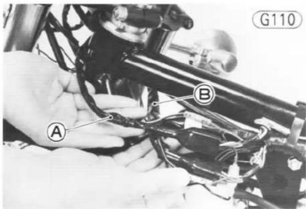
A. Right Switch Wiring Harness
B. Left Switch Wiring Harness
- Put together the right switch housing, and tighten its screws. The upper half of the housing has a small projection which fits into a hole in the handlebar (Fig. G67).
- Check and adjust the following items.
○Steering (Pg. 35)
○Front Brake
○Clutch (Pg. 25)
○Throttle Cable (Pg. 21)
STEERING STEM BEARING
Removal:
- Remove the steering stem (Pg. 135).
●To remove the outer races pressed into the head pipe, insert a bar into the head pipe, and hammer evenly around the circumference of the opposite race to drive it out.
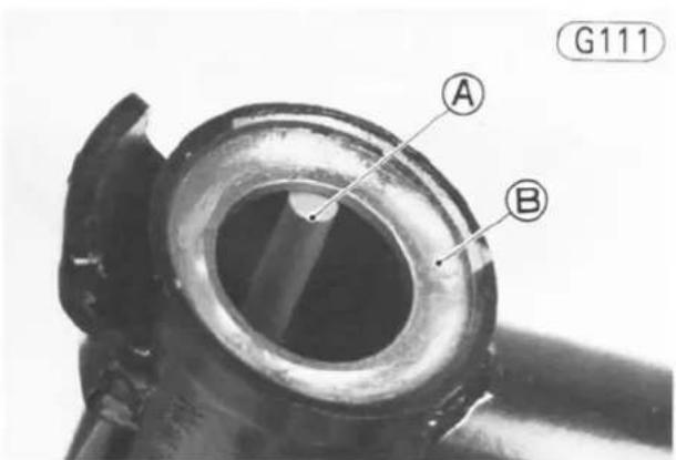
A. Bar
B. Outer Race
●To remove the lower inner race, which is pressed onto the steering stem, grip the stem in a vise, and use a metal rod and hammer as shown in the figure.
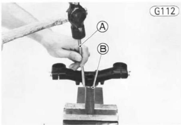
A. Rod
B. Lower Inner Race
Installation:
- Apply oil to the outer races, and then drive them into the head pipe using the stem cup driver and the bearing driver holder (special tools). Be sure to press them until they stop at the stepped portion in the head pipe.
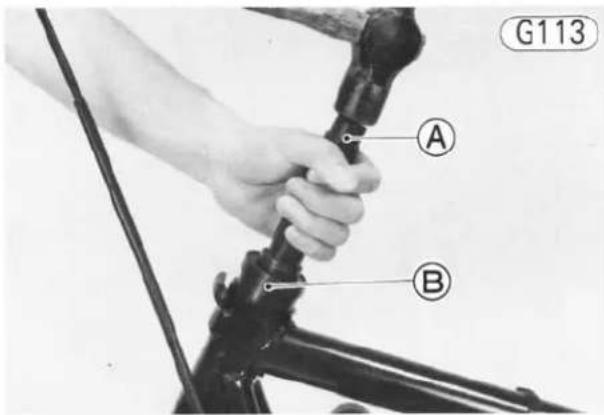
A. Bearing Driver Holder (57001-139)
B. Stem Cup Driver (57001-138)
- Apply oil to the lower inner race, and then drive it onto the steering stem using the stem bearing driver and adapter (special tools). Be sure to press it until it stops at the stem base.

A. Stem Bearing Driver (57001-137)
B. Adapter (57001-294)
●Install the steering stem (Pg. 138).
FRONT FORK
Removal (each fork leg):
- Remove the front wheel (Pg. 107 for a disc-brake model or Pg. 109 for the drum brake model).
- Remove the bolts and lockwashers that hold the front fender to the left fork leg, and remove the fender.
●To remove the left fork leg of the disc-brake model, remove the caliper mounting bolts and rest the caliper on some kind of stand so that it does not dangle. - Loosen the upper and lower clamp bolt.
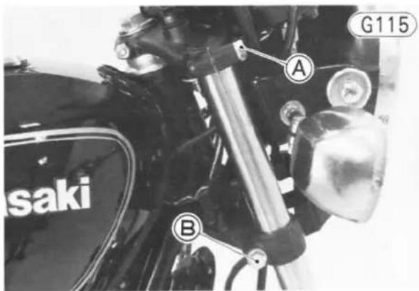
A. Upper Clamp Bolt
B. Lower Clamp Bolt
- With a twisting motion, work the fork leg down and out.
Installation Notes (each fork leg):
- Slide the fork leg up through the lower and upper clamps until the upper end of the front fork inner tube is even with the upper surface of the stem head.

A. Upper Clamp Bolt
C. Stem Head
B. Inner Tube End
Front Fork
G117

- Dust Seal
- Retainer
- Oil Seal
- Spacer
- Piston Ring
- Piston and Cylinder Unit
- Spring
- Cylinder Base
- Outer Tube
-
Gasket
-
Drain Screw
- Gasket
- Allen Bolt
- Cap
- Retaining Ring
- Top Plug
- O Ring
- Bolt
- Lockwasher
-
Fork Cover
-
Stem Base Cover
- Damper Ring
- Rubber Damper
- Lockwasher
- Bolt
- Spring
- Inner Tube
- Stem Head
- Bolt
-
Nut
-
Lockwasher
- Steering Stem
- Stem Base
- Outer Tube
- Stud
- Axle Clamp
- Lockwasher
-
Nut
-
Tighten the front fork upper clamp bolts to 2.0 kg-m (14.5 ft-lbs) of torque and the lower clamp bolt to 3.0 kg-m (22 ft-lbs) of torque.
- Tighten the caliper mounting bolts to 4.0 kg-m (29 ft-lbs) of torque.
Disassembly:
- Remove the cap ⑭ from the inner tube.
- Press the top plug 16 to remove the top plug retaining ring 15, and then remove the top plug and spring 26.
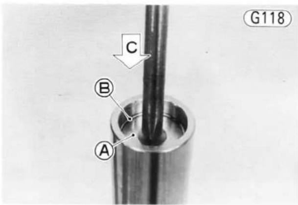
A. Top Plug
C. Press down
B. Retaining Ring
- Pour the oil into a suitable container, pumping as necessary to empty out all the oil.
- Stop the cylinder ⑥ from turning by using the front fork cylinder holder handle and holder adapter (special tools). Unscrew the Allen bolt 13 and gasket 12 from the bottom of the outer tube ⑨ or 34, and then separate the inner tube from the outer tube by pulling it out.
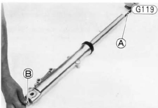
A. Front Fork Cylinder Holder Handle and Adapter (57001-183, 57001-1011)
B. Allen Wrench
- Remove the dust seal ① off the outer tube ⑨.
- Slide or push the cylinder ⑥ and its spring ⑦ out the top of the inner tube.
- Remove the cylinder base ⑧ out the top of outer tube.
- Remove the retainer ② from the outer tube with a sharp hook, and pull out the oil seal ③. It may be necessary to heat the outer tube around the oil seal before pulling it out.

A. Retainer
B. Oil Seal
Assembly Notes:
- Apply liquid gasket to both sides of the gasket 12, apply a non-permanent locking agent to the Allen bolt, and tighten it using the front fork cylinder holder handle and holder adapter (special tools) to stop the cylinder from turning. The torque for the Allen bolt is 1.8 kg-m (13.0 ft-lbs).
- Replace the oil seal with a new one, apply oil to the outside, and install it with the front fork oil seal driver (special tool).
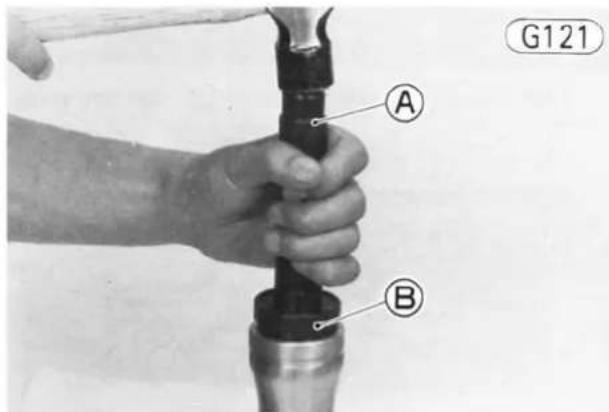
A. Holder (57001-139)
B. Driver (57001-293)
- Install the spring 26 with the smaller diameter end facing down.

A. Smaller Diameter End
- Refill with 146\~154 cc of fresh SAE 5W20 oil.
SWING ARM
Removal:
- Remove the rear wheel (Pg. 118).
- Move the swing arm up and down to check for abnormal friction.

- Remove the pivot shaft nut, and pull out the pivot shaft.

A. Pivot Shaft Nut
- Pull back the swing arm. A cap on each side of the pivot will also drop off.
Installation:
●Lubricate the swing arm pivot (Pg. 210).
- Apply grease to the cap inner surfaces and install the cap on each side of the pivot of the swing arm.
- Install the rear shock absorber lower mounting bolts finger tight. Each bolt has a lockwasher. This is to help hold the swing arm in place when installing the pivot shaft.
- Position the pivot of the swing arm into its place in the frame, and slide in the pivot shaft from right to left. A screwdriver inserted into the left side of the pivot will keep the left cap in place.
- Install the pivot shaft nut, and tighten the nut to 9.0 kg·m (65 ft·lbs) of torque.
- Install the side stand return mechanism, and hook the return mechanism spring on the pins.

A. Spring
●Install the rear wheel (Pg. 119).
- Adjust the drive chain (Pg. 30) or belt (Pg. 31).
-Adjust the rear brake (Pg. 34).
- For the models that have the automatic side stand return mechanism, adjust its mechanism (Pg. 38).
Disassembly:
NOTE: As the swing arm needle bearings will be damaged upon removal, be sure to have new ones on hand prior to disassembly.
- Remove the caps 2, and pull out the swing arm sleeve 6.
- Remove the screws (2), and take off the chain (or belt) guard. Each screw has a lockwasher and flat washer.

A. Chain (or Belt) Guard
B. Torque Link
- Remove the clip 12 from the torque link bolt 8. Take out the nut 11 and bolt, and then remove the torque link 9 from the swing arm 4.
- Insert a bar into one side, hammering on it lightly to knock out the needle bearing ③ on the opposite side.
- Use the bar again to knock out the other bearing.
Assembly Notes:
-
Inspect the swing arm sleeve (Pg. 209), and replace it with a new one if it has worn past the service limit or is damaged. Also, replace both needle bearings whenever the sleeve is replaced.
-
Replace the needle bearings with new ones if either one has been damaged or removed. Apply oil to the outside surface of the bearings before installing them with a press.
- Install the torque link and then tighten the torque link nut to 3.3 kg·m (24 ft·lbs) of torque. Insert the safety clip through the bolt.
- Adjust the drive chain (Pg. 30) or belt (Pg. 31) after installing the swing arm.
Swing Arm
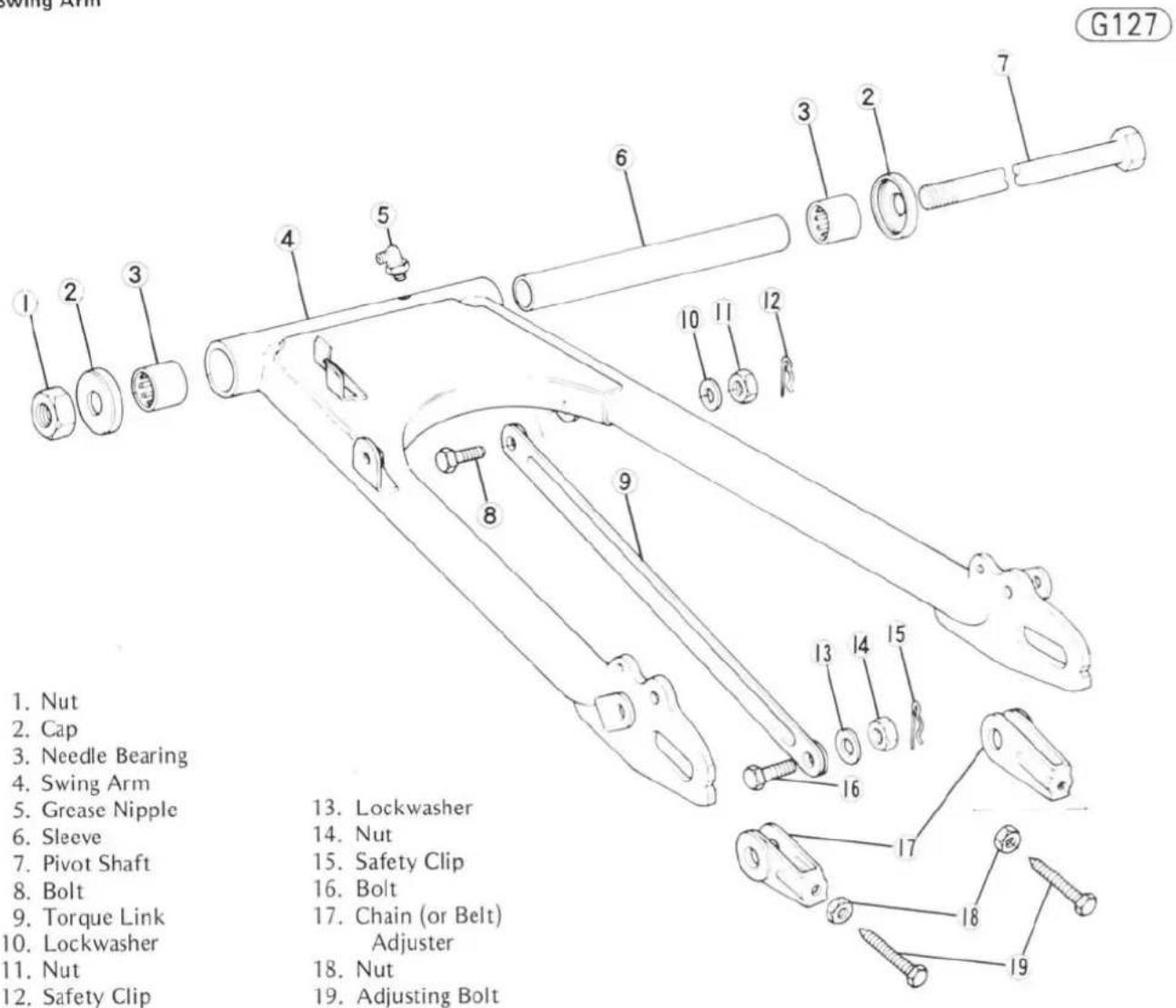
Maintenance—Engine
Table of Contents
AIR CLEANER 146
FUEL TANK, FUEL TAP 147
CARBURETORS 148
ROCKER ARMS, SHAFTS 155
CAMSHAFT 155
CAMSHAFT CHAIN, GUIDES, TENSIONER 157
CYLINDER HEAD, VALVES 158
CYLINDER BLOCK, PISTON 164
CRANKSHAFT, CONNECTING RODS.... 167
BALANCER MECHANISM 171
CLUTCH....173
PRIMARY CHAIN 175
TRANSMISSION 176
ENGINE LUBRICATION.... 181
BALL, NEEDLE BEARINGS.... 185
OIL SEALS. 185
MUFFLERS 185

146 MAINTENANCE—ENGINE
AIR CLEANER
A properly maintained air cleaner ensures that only clean, filtered air is supplied through the carburetor to the engine. If the air is supplied directly without filtering, dirt and dust from the air will clog carburetor passages causing the engine to run poorly. The dust that enters the engine will also act like grinding compound, wearing down the cylinders, pistons, and rings. If the air cleaner element is damaged, the result will be the same as if no element were used.
An air cleaner element clogged with dirt chokes the air supply to the engine, resulting in an overly rich fuel/air mixture and inefficient combustion. This in turn causes overheating from carbon build-up, and reduced engine power.
Cleaning
The air cleaner element must be cleaned periodically (Pg. 16). In extremely dry, dusty areas, the element will need to be cleaned more often. After riding through rain or on muddy roads, the element should be cleaned immediately.
Dry type element (KZ440B, C):
- Remove the air cleaner element (Pg. 49).
- Clean it in a bath of a high flash-point solvent, and then dry it from the inside using compressed air. Since this is a dry-type element, do not use kerosene or any fluid which would leave the element oily.

WARNING Clean the element in a well-ventilated area, and take care that there is no spark or flame anywhere near the working area. Because of the danger of highly flammable liquids, do not use gasoline or low flash-point solvents to clean the element.
Oiled type element (KZ440A, D):
- Remove the air cleaner element (Pg. 49).
- Clean the sponge filter in a bath of a high flash-point solvent, and squeeze it dry.
●After cleaning, saturate the sponge filter with SE class SAE 30 oil, squeeze out the excess, then wrap it in a clean rag and squeeze it dry as possible. Be careful not to tear the sponge filter.
Air Cleaner
H2

-
Screw
-
Tool Tray
-
Air Cleaner Duct
-
Spring Band
-
Air Cleaner Housing
-
Air Cleaner Element
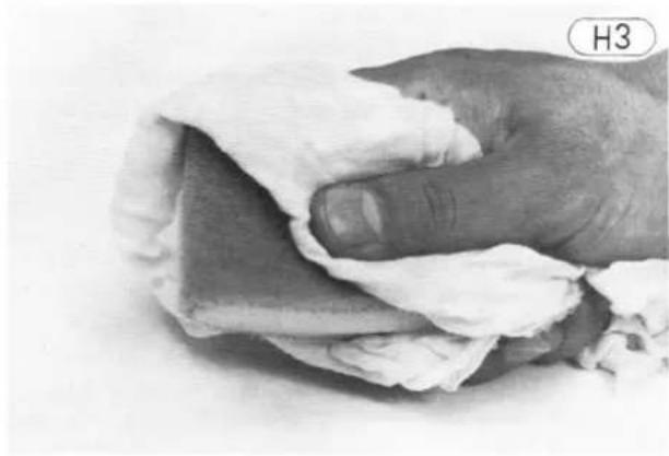
WARNING
-
Clean the element in a well-ventilated area, and take ample care that there or flame anywhere near the working
-
Because of the danger of highly flammable liquids, do not use gasoline or a low flash-point solvent to clean the element.
- A break in the element material or damage to the sponge gasket will allow dirt and dust to pass through into the carburetor and eventually damage the engine. If any part of the element is damaged, the element must be replaced.
Replacement
If the sponge gasket on the side of the element come loose, stick them back on with an adhesive sealant. If the sponge or the element is damaged or holed, replace the element.
Since repeated cleaning opens the pores of the element, replace it with a new one in accordance with the Periodic Maintenance Chart (Pg. 16). Also, if there is a break in the element material or any other damage to the element, replace the element with a new one.
with the tap in the "Reserve" position, fuel flows through the tap from the bottom of the tank. The "Pri" position bypasses the automatic control and is useful for priming the engine after running out of gas. The fuel tap contains a filter to filter out dirt.
Fuel Tap
H4

-
O Ring
-
Tap Lever
-
Spring
-
Vacuum
-
Diaphragm
-
O Ring
-
Fuel
-
Filter
FUEL TANK, FUEL TAP
For the standard type: The fuel tank capacity is 14 liters, 1 liter of which forms the reserve supply. For the chopper type: The fuel tank capacity is 12 liters, 2 liters of which form the reserve supply. A cap is attached to the top of the tank, and a fuel tap to the bottom. An air vent is provided in the cap to prevent an air lock, which would hinder fuel flow to the carburetors.
Fuel tap construction is shown in Fig. H4. The fuel tap is an automatic type which shuts off the fuel supply when the engine is stopped in the ON or RES position. The fuel tap has three positions: ON, RES (reserve), and PRI (prime). With the tap in the "On" position, fuel flows through the tap by way of the main pipe until only the reserve supply is left in the tank;
The automatic valve in the fuel tap operates as follows: When the engine is running, negative pressure (vacuum) is created at the carburetor due to engine intake. This engine intake vacuum is transmitted to the diaphragm vacuum chamber in the fuel tap through the vacuum hose and the check valve. The vacuum pulls the diaphragm 3 against its spring pressure, and the O ring 1 on the diaphragm assembly 3 is pulled out of its seat, permitting fuel to flow between the O ring and seat. When the engine stops and vacuum is lost, air enters the diaphragm vacuum chamber through the vacuum hose, bringing chamber pressure back up to atmospheric and allowing the diaphragm spring 2 to push the diaphragm back into place and hold the O ring against the seat.
148 MAINTENANCE—ENGINE
The check valve in the diaphragm cover keeps the pressure in the diaphragm vacuum chamber negative in spite of the pulsation of the intake vacuum while the engine is running so that fuel flows smoothly.
Inspection and cleaning
If fuel leaks from the tank cap or from around the fuel tap, the cap gasket or tap O ring may be damaged. Visually inspect these parts, and replace them if necessary.
Examine the air vent in the tank cap to see if it is obstructed. Use compressed air to clear an obstructed vent.
Any water in the fuel tank and the carburetors can be drained to loosen the drain screws through the overflow tubes (Pg. 27). If water cannot be drained completely, remove the fuel tap (Pg. 51), and flush out the tank with a high flash-point solvent. For thorough cleaning of the carburetors, remove and disassemble the carburetors (Pg. 52).
If there is any doubt about the condition of the fuel tap, remove and disassemble the fuel tap (Pg. 51), and inspect the parts. Especially examine the diaphragm assembly. Make sure the O ring and its seat are clean and undamaged; if the O ring is prevented from seating properly or if it is damaged, fuel flow will not stop when the engine is stopped, and may overflow from the carburetors. Visually inspect the diaphragm. If there is any tear or other damage, the diaphragm assembly should be replaced.

A. Diaphragm
B. "O" Ring Seat
C. "O" Ring
Clean the air and fuel passages by lightly applying compressed air to the passage openings.

Do not use wire for cleaning as this could damage the check valve, O ring seat, and ting surfaces.
CARBURETORS
The carburetors perform the function of mixing the fuel and air in the proportions necessary for good engine performance at varying speeds and loads. In order for them to function satisfactorily, they must be kept well adjusted and maintained. The throttle cable adjustment (Pg. 21), idling and synchronizing adjustments (Pg. 22) are covered in the Adjustment section. The discussion here concerns the fundamentals of carburetor operation, fuel level adjustment, and the cleaning and replacement of carburetor parts.
A linkage mechanism turns each carburetor butterfly valve the same amount in response to throttle grip movement so that the carburetors operate in unison. As the throttle grip is turned counterclockwise, the throttle cable turns the carburetor pulley, which through the linkage mechanism opens the butterfly valves. As the throttle grip is turned clockwise or is released, the return spring closes the butterfly valves.
One of the basic principles in carburetor operation is that the pressure exerted by a moving body of air is less than atmospheric pressure. As the engine draws air in through the carburetor bore, the air pressure in the carburetor bore is less than the air pressure in the float chamber, which is at atmospheric pressure. This difference in air pressure forces the fuel up through the passages into the carburetor bore where it is then atomized by the air, which is flowing at high speed to the engine.
Another important principle is the Venturi Principle, which states that when an air passage narrows, moving air flows faster, exerting even less pressure. For example, at low speeds (0 \~ 1/4 throttle) the vacuum piston is at its lowest position, forming what is called the "primary venturi". Since the engine intake requires less air at lower engine speeds, there would not be enough air flow speed for sufficient fuel to be forced up through the jets unless the passage (carburetor bore) above the jets is constricted. The low position of the vacuum piston constricts this passage so that there will be sufficient
Table H1 Carburetor Specifications
| Type | Jet Needle | Main Jet | Air Jet | Pilot Jet | Service Fuel Level | ||||
| Primary | Secondary | Pilot | Primary Main | Secondary Main | |||||
| KZ440-A, D | CV36G CV32 | N02A G 003002 | #70 U #62 G #78 | #85 U #88 G #72 | #125 G #130 | #130 G #150 | #50 | #35 | 3~5 mm G 1.5~3.5 mm |
| KZ440-B, C | N03A G 003303 | #75 U #68 G #70 | #88 U #90 G #85 | #125 G #115 | #50 G #60 | ||||
①: US model only
©: West German model only
Carburetors
H6

- Upper Chamber Cover
- Fast Idle Link
- Return Spring
- Cable Bracket
- Spring
- Spring
- Pilot Screw
- Diaphragm
-
Vacuum Piston
-
Air Jet
- Carburetor Body
- Jet Needle
- Needle Jet
- Bleed Pipe
- Float Bowl
- Float
- Primary Main Jet
-
Needle Jet Holder
-
Secondary Main Jet
- Overflow Pipe
- Plastic Plug
- Pilot Jet
- Float Valve Needle
- Idle Adjusting Screw
- Fuel Hose
- 3-way Joint
-
Drain Screw
-
Overflow Tube
- Clamp
- Choke Link
- Fast Idle Cam
- Choke Valve
- Choke Lever
- Upper Mounting Plate
Carburetor trouble can be caused by dirt, wear, maladjustment, or improper fuel level in the float chamber. A dirty or damaged air cleaner can also alter the fuel-to-air ratio.
Table H2 Mixture Trouble Symptoms
Poor running
Overheating
Exhaust smokes excessively
The following explanation of the functioning and maintenance of the carburetors covers the four main systems for fuel regulation and supply.
air flow speed for pressure difference to force the necessary amount of fuel up through the jet.
The amount of fuel passing through a jet depends both on the size of the jet and on the speed of the air flow over the jet. The speed of this air flow is in turn determined both by the engine rpm and by the dimensions of the passage (varied with the vacuum piston) just above the jet. The size of the jet openings, the various dimensions of the air passages, and the engine rpm are correlated through carburetor design so that, when properly adjusted, the carburetor meters (measures) the fuel and air in the correct proportions at different throttle openings.
The carburetor specifications (Table H1) have been chosen for best all around performance.
Table H3 Carburetor Systems
| System | Function |
| Starter System | Supplies the necessary rich mixture for starting a cold engine. |
| Pilot System | Supplies fuel at idling and low speeds. |
| Main System | Supplies fuel at medium and high speeds. |
| Float System | Maintains the fuel at a constant level in the float chamber. |
CAUTION
-
Remove the diaphragm and float before cleaning the carburetor with comor they will be damaged.
-
Remove as many rubber or plastic parts from the carburetors (Table H4) as possible before cleaning the carburetors with a cleaning solution. This will prevent damage or deterioration of the parts.
- The carburetor body has plastic parts (Table H4) that cannot be removed. DO NOT use a strong carburetor cleaning solution which could attack these parts; instead, use a mild cleaning solution safe for plastic parts.
- Do not use wire for cleaning as this could damage the jets.
Table H4 Carburetor Rubber Parts and Plastic Parts
| Parts | Quantity | Removable |
| Cable Bracket Washers | 2 | Yes |
| Floats | 2 | Yes |
| Float Bowl O Rings | 2 | Yes |
| Fuel Hose | 1 | Yes |
| Idling Adjusting Screw | 1 | Yes |
| Drain Screw O Rings | 2 | Yes |
| Overflow Tubes | 2 | Yes |
| Pilot Screw O Rings | 2 | Yes |
| Pilot Jet Rubber Plugs | 2 | Yes |
| 3-way Joint O Rings | 4 | Yes |
| Vacuum Hose | 1 | Yes |
| Vacuum Pistons | 2 | Yes |
Starter System
Fig. H7 shows the starter system, which includes the choke lever, choke valve, fast idle cam, and idle link.
The starter system provides the exceptionally rich fuel/air ratio that is necessary to enable easy starting when the engine is cold. When starting the engine, the choke valves close down the carburetor bores by pulling up the choke lever. Since the choke valves close down the carburetor bores, a high intake vacuum (suction or low pressure) is developed at the engine side of the carburetor bores. The choke valves are slightly opened by a high intake vacuum, and air is drawn into the carburetor bores. As the engine is cranked over, fuel is drawn in from the float chamber through the main jets and pilot jet. This fuel is then drawn into the carburetor, mixed with the air drawn in through the lower part of the choke valve, and drawn into the engine.
The engine must be run at a faster than normal idle speed to prevent the engine from stalling until it reaches operating temperature. To accomplish this, the fast idle cam pushes the idle link when the choke lever is pulled up, and the throttle valve is held open an amount sufficient to prevent stalling.
In order for the starter system to work properly, the choke lever must be pushed up fully so that the choke valve will be kept closed and sufficient vacuum can be built up at the engine of the carburetor bore. Clogged pilot jet, main jets, pilot air jet, needle jet holder and main jet bleed pipe will cause insufficient atomization, thus impairing starter efficiency. Fuel mixture trouble results if choke linkage mechanism, pilot and main system is defective. Fuel mixture trouble results if the choke valve does not open fully after the choke lever is returned.

- Choke Valve
Cleaning and inspection (See cautions on Pg. 150)
Disassemble the carburetor, and wash the main jets, pilot jet, needle jet holder, main jet bleed pipe, air jets, and air passage with a high flash-point solvent, blowing them clean with compressed air. If necessary, use a bath of automotive type carburetor cleaner.
Pull up and push down the choke lever to check that the choke valves move smoothly. The choke valves must close the carburetor bores completely when the lever is pulled up, and must open fully when the lever is pushed down. If necessary, adjust the choke linkage. To check that the choke valve spring is working properly, push on the lower part of the choke valve. The valve must move smoothly, and must close by spring tension.
If the choke valve does not work properly, replace the carburetor body.

A. Choke Valve
Fast Idle Mechanism
H9

- Choke Lever
- Fast Idle Cam
- Fast Idle Link
- Butterfly Valve
- Pulley
- Idle Adjusting Screw
Pilot System
Fig. H10 shows the pilot system, which includes the pilot air jet ⑩, pilot jet ⑧, primary main jet ⑥, bypass outlet ⑤, pilot outlet ④, and pilot screw ①.
The pilot system determines the operation of the carburetor from 0 to 1/4 throttle opening. At small throttle openings, almost no fuel is drain through the main system due to insufficient air flow. Instead, the fuel is drawn through the main and pilot jets as a result of the low pressure (suction) brought about by the demand for air by the engine and the limited but relatively fast flow of air past the pilot outlet. The almost closed position of the butterfly valve restricts the carburetor bore air flow, preventing it from relieving the low pressure created by the engine around the pilot outlet while the Venturi effect (the narrower the air passage, the faster the flow of air) at the engine side of the butterfly valve further reduces the low pressure.
Pilot System
H10

- Pilot Screw
- Primary Main Jet
- Spring
- Plastic Plug
- Carburetor Bore
- Pilot Jet
- Pilot Outlet
- Float Chamber
- Bypass Outlet
- Pilot Air Jet
Pilot System Fuel and Air Supply
H11
![graph TD A["Fuel Tank"] --> B["Float Chamber"] B --> C["Primary Main Jet"] C --> D["Pilot Jet"] D --> E["Pilot Passage"] E --> F["Pilot Screw"] F --> G["Pilot Outlet"] G --> H["Bypass Outlet"] H --> I["Carburetor Bore"] I --> J["Engine"] K["Air Cleaner"] --> L["Pilot Air Jet"] L --> D L --> E](/content/2026/06/1261528/images/f6ab3f0a0f76c056dc1e44094eae893e21288c263b7777a6cb6bab9cddff8c02.jpg)
The supply of the fuel and air in the pilot system is shown in Fig. H11. At idling and slightly above, the
152 MAINTENANCE—ENGINE
fuel passes through the main jet, and is then metered at the pilot jet, which the fuel mixes with air metered by the pilot air jet. Then, the fuel passes through the pilot passage, where the pilot screw affects the flow, through the pilot outlet into the carburetor bore, and to the engine. As the butterfly valve turns a little more, the butterfly valve position extends the low pressure area to the pilot bypass, allowing fuel to bypass part of the pilot passage to go directly to the carburetor bore such that the supply of fuel increases sufficiently with engine need.
Fig. H12 shows throttle opening versus fuel flow for the main and pilot systems. If trouble occurs in the pilot system, not only are starting and low speed running affected, but the transition from pilot to main system is not smooth as the throttle is opened, causing a drop in engine efficiency. Pilot system trouble might be due to maladjustment; a dirty or loose pilot jet, or pilot air jet; or clogging of the main jet, pilot passage, pilot outlet, or bypass outlets.
Fuel Flow Characteristics
H12
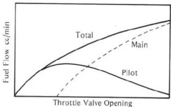
Cleaning and replacement
(See cautions on Pg. 150)
Disassemble the carburetor, and wash the disassembled parts and air passage with a high flash-point solvent, blowing them clean with compressed air. If necessary, use a bath of automotive type carburetor cleaner. For the model except US model, remove the pilot screw, and check that the tapered portion is not worn or otherwise deformed. If it is, replace the screw. If the screw O ring is damaged, replace the O ring.  A. Tapered Portion B. "O" RingMain System
Fig. H14 shows the main system, which consists of the main jets ⑪, ⑮, main jet bleed pipe ⑩, needle jet holder ⑭, jet needle ④, needle jet ⑬, vacuum piston ⑦, spring ⑧, and main air jet ⑨, ⑧. Main System H14  1. Diaphragm 2. Vacuum Piston 3. Spring 4. Jet Needle 5. Carburetor Bore 6. Choke Valve 7. Primary Main Air Jet 8. Secondary Main Air Jet 9. Butterfly Valve 10. Bleed Pipe 11. Primary Main Jet 12. Float Chamber 13. Needle Jet 14. Needle Jet Holder 15. Secondary Main Jet Main System Fuel and Air Supply H15  Fig. H15 shows the supply of fuel and air in the main system. From about 1/4 1/2 throttle opening, the air flow past the main jet bleed pipe is sufficient to cause fuel to be drawn through the main system, and from about 1/2 throttle opening, the air flow past the needle jet outlet is sufficient too. The fuel passes through the primary main jet and then part of it goes through the pilot jet as in the pilot system while the rest of it passes straight up through the main jet bleed pipe at about 1/4 1/2 throttle opening, and from about 1/2 throttle opening, the fuel passes through the secondary main jet and then it goes straight up through the space in the needle jet not blocked by the jet needle and into the carburetor bore, where it is atomized by the air flow to the engine. The needle jet holder and main jet bleed pipe have holes to admit the air metered by the main air jets. This air mixes with the fuel in the needle jet holder and main jet bleed pipe to prepare the fuel for better atomization in the carburetor bore. The lower part of the jet needle is tapered and extends down into the needle jet and needle jet holder. It is fixed to the vacuum piston, and thus rises up in the needle jet and needle jet holder as the vacuum piston rises. From the time the vacuum piston starts rising, from about 1/4 throttle, until it reaches most of the way up in the carburetor bore, the fuel is metered primarily by the primary main jet and secondarily by the jet needle taper. As the jet needle rises, the needle to jet clearance increases, thereby increasing the amount of fuel that can pass up through the jet. The vacuum piston is attached to the diaphragm and rises only between 1/4 and 3/4 throttle. Through the holes in the bottom of the piston, the air pressure in the chamber above the diaphragm is reduced by engine intake vacuum. The air vent maintains atmospheric pressure in the chamber under the diaphragm. As engine speed increases, air pressure in the upper chamber decreases. The difference between this pressure and atmospheric pressure in the lower chamber becomes greater. The force of the spring and the weight of the piston are overcome, and the piston rises to an extent corresponding to this pressure difference. The diaphragm is made of rubber and absorbs the vibration caused by engine intake pulsing to prevent the vacuum piston from wearing. As shown in Fig. H16 the quantity of air drawn in by the engine intake is in direct proportion to engine rpm, and the speed of the air flow is constant while the vacuum piston rises from 1/4 to 3/4 throttle. Were the size of the air passage above the needle jet to change simultaneously with throttle movement rather than with engine intake (demand), the speed of the air flow in the air passage might even drop during a rapid increase in throttle due to the Venturi effect, causing a slight stall in acceleration. However, the vacuum piston-butterfly valve arrangement controls both the air and fuel supply at sudden throttle for smooth and immediate engine response. At 1/4 throttle the vacuum piston reaches its highest position, forming the “secondary venturi” to permit maximum engine output. At near full throttle openings, the cross-sectional area of the needle to jet clearance becomes greater than the cross-sectional area of the main jet. At these openings, the fuel drawn up into the carburetor bore is limited by the size of the main jet rather than the needle to jet clearance. Venturi Principle H16    Trouble in the main system is usually indicated by poor running or lack of power at high speeds. Dirty or clogged main jets will cause the mixture to become too lean. An overly rich mixture could be caused by clogging of the main air jets, its air passage, or the air holes in the main jet bleed pipe and needle jet holder; by needle jet or needle wear (increasing clearance); by loose main air jets; or by a loose needle jet.Cleaning and replacement (See cautions Pg. 150)
Disassemble the carburetor, and wash the disassembled parts and air passage with a high flash-point solvent, blowing them clean with compressed air. If necessary, use a bath of automotive type carburetor cleaner.154 MAINTENANCE—ENGINE
Visually inspect the diaphragm. If there is any tear or other damage, the diaphragm should be replaced. A worn needle jet or jet needle should be replaced.Float System
Fig. H17 shows the float system, which consists of the float 1, float valve needle 3, float valve seat 4, float pin 5, and overflow pipe 2.Float System H17
 1. Float 4. Valve Seat 2. Overflow Pipe 5. Float Pin 3. Valve Needle The float system serves to keep a more or less fixed level of fuel in the carburetor float chamber at all times so that the fuel mixture to the engine will be stable. If the fuel level in the float chamber is set too low, it will be more difficult for fuel to be drawn up into the carburetor bore, resulting in too lean a mixture. If the level is set too high, the fuel can be drawn up too easily, resulting too in rich a mixture. The fuel level is defined as the vertical distance from the center of the carburetor bore to the surface of the fuel in the float chamber. The fuel level is maintained at a constant value by the action of the float valve, which opens and closes according to the fuel level. As fuel flows through the float valve into the chamber, the fuel level rises. The float, rising with the fuel level, pushes up on the valve needle. When the fuel reaches a certain level, the valve needle is pushed completely into the valve seat, which closes the valve so that no more fuel may enter the chamber. As the fuel is drawn up out of the float chamber, the fuel level drops, lowering the float. The needle no longer blocks the float valve, and fuel once again flows through the float valve into the chamber. NOTE: It is impractical to measure the actual design fuel level. Service fuel level is defined as the vertical distance from the bottom edge of the carburetor body to the surface of the fuel in the float chamber. Measuring the service fuel level is an indirect method of inspecting for correct design fuel level.Service fuel level measurement and adjustment
If the motorcycle exhibits symptoms of improper fuel mixture, measure the service fuel level. Turn the fuel tap to the "ON" or "RES" position, and attach the fuel level gauge (special tool) to the open end of the overflow tube. Hold the gauge against the side of the carburetor so that the "0" line is even with the bottom edge of the carburetor body. Turn the fuel tap to the "PRI" position, and turn out the drain screw 1\~2 turns. Wait until no air bubbles can be seen rising up through the fuel from the overflow tube, and read the service fuel level in the gauge. NOTE: Measure the service fuel level keeping the carburetors fully perpendicular to the ground.Service Fuel Level Measurement H18
 1. Fuel Level Gauge (57001-1017) Table H5 Service Fuel Level| Standard |
| 3 ~ 5 mm (West German Model: 1.5 ~ 3.5 mm) from the bottom edge of the carburetor body to the fuel level. |
Cleaning and replacement (See cautions Pg. 150)
If dirt gets between the needle and seat, the float valve will not close and fuel will overflow. Overflow can also result if the needle and seat become worn. If the needle sticks closed, no fuel will flow into the carburetor. Remove the carburetor, and take off the float bowl and float. Wash the bowl and float parts in a high flash-point solvent. Use carburetor cleaner if necessary on the float bowl and metal parts. Blow out the fuel overflow pipe with compressed air. Examine the float, and replace it if it is damaged. If the needle is worn as shown in the diagram, replace it. If the seat is worn, the entire carburetor must be replaced. Valve Needle H20  Good  BadROCKER ARMS, SHAFTS
There are four rocker arms and shafts in the cylinder head cover. The two arms and shafts to the front control the two exhaust valves, while the two to the rear control the two inlet valves. The rocker arms are made of a special steel alloy for durability, and each arm surface which makes contact with the cam and the valve stem has been heat-treated to achieve superior surface hardness. An oil hole in each rocker arm enables oil to lubricate between the arm and shaft. Excessive clearance between a rocker arm and shaft results in engine noise.Rocker arm/shaft wear
Visually inspect where the cam and valve stem wear on each arm. If there is any damage or uneven wear, replace the arm. Measure the inside diameter of each arm with a cylinder gauge. If it exceeds the service limit, replace the arm. Measure the diameter of each shaft where the arm fits. If the diameter is less than the service limit, replace the shaft.  Table H6 Rocker Arm Inside Diameter| Service Limit | 13.05 mm |
| Service Limit | 12.94 mm |
CAMSHAFT
The engine has an overhead camshaft (OHC) at the top of the cylinder head. The camshaft has four cams, two for the two inlet valves and two for the two exhaust valves. There is a sprocket at the center of the crankshaft and at the center of the camshaft. A chain placed over these sprockets enables the crankshaft to turn the camshaft so that the valves will be opened and closed at the proper times during each rotation of the engine. The sprocket has a mark so that valve timing (the time that each valve is opened) can be reset correctly any time the camshafts are removed for inspection or repairs (See Pg. 61). However, since the time, amount, and duration that each valve is opened (valve timing) changes with cam wear and journal wear, the camshaft should be inspected periodically and whenever timing trouble is suspected. If the valves do not open at the right times or if they do not open the correct amount or for the proper duration, there will be a decrease in combustion efficiency, causing a loss of engine power and leading to serious engine trouble. Valve Timing H22 Cam wear
Remove the camshaft, and measure the height of each cam with a micrometer. If the cams are worn down past the service limit, replace the camshaft. Cam Height Measurement H23  Table H8 Cam Height| Service Limit | 38.25 mm |
Journal, bearing wear
The journal wear is measured using plastigauge (press gauge), which is inserted into the clearance to be measured. The plastigauge indicates the clearance by the amount it is compressed and widened when the parts are assembled. Remove the cylinder head cover and camshaft caps, and wipe each journal and camshaft cap surface clean of oil. Cut strips of plastigauge to journal width. Place a strip on each journal parallel to the camshaft and so that the plastiguage will be compressed between the journal and camshaft cap. Now, tighten the camshaft cap bolts in the correct sequence to the specified torque (Pg. 43). Next, remove the camshaft cap again, and measure the plastigauge width to determine the clearance between each journal and the camshaft cap. If any clearance exceeds the service limit, measure the diameter of the camshaft journal. If camshaft replacement does not bring the journal clearance within the service limit, replace the cylinder head and camshaft caps.  A. Plastigauge Table H9 Camshaft Journal/Camshaft Cap Clearance| Service Limit | 0.29 mm |
| Service Limit | 24.93 mm |
Camshaft runout
Remove the camshaft and take the sprocket off the shaft. Set the shaft on V blocks at the outside journals as shown in the figure. Measure runout with a dial gauge at the sprocket mounting location, and replace the shaft if the runout exceeds the service limit.  Table H11 Camshaft Runout| Service Limit | 0.1 mm |
CAMSHAFT CHAIN, GUIDES, TENSIONER
The camshaft chain, which is driven by crankshaft, drives the camshaft at one-half crankshaft speed. For maximum durability and minimum noise, and endless-type silent chain with no master link is used. The automatic camshaft chain tensioner of ball-lock type is utilized for this machine. Periodic adjustment of the tensioner is not needed since chain slack is removed automatically. The tensioner consists of push rod 1, short spring 2 balls and retainer 3, circlip 4, washer 5, long spring 6, sleeve 7 (press-fifted into the tensioner body), tensioner body 8, and bolt 9. When the slack appears on the chain, the push rod is pushed out to the chain by the long spring, and it cannot be pushed back in because of the lock balls locking on the ramp of the sleeve pressed into tensioner body. The bolt 9 is used to keep the push rod from flying out during installation. Camshaft Chain Tensioner H27  1. Push Rod 2. Short Spring 3. Balls and Retainer 4. Circlip 5. Washer 6. Long Spring 7. Sleeve 8. Tensioner Body 9. Lock BoltCamshaft chain wear
Hold the chain taut with a force of about 5 kg in some manner, and measure a 20-link length. Since the camshaft chain may wear unevenly, take measurements at several places. If any measurement exceeds the service limit, replace the chain. Chain Length Measurement H28  Table H12 Camshaft Chain 20-link Length| Service Limit | 128.8 mm |
Chain guide wear
Remove the chain guides, and inspect them visually. Replace the guide if the rubber or any other portion is damaged. Measure the depth of the grooves where the chain links run. Replace the guide if the wear exceeds the service limit. Chain Guide Rubber Wear H29  Table H13 Camshaft Chain Guide Wear| Front | Rear | |
| Service Limit | 3.6 mm | 4.5 mm |
Chain tensioner inspection
Remove the camshaft chain tensioner. Visually inspect the push rod, the sleeve in the tensioner body, and the lock ball. If there is any damage or dent, replace the part with a new one. Measure the long spring free length. Replace the spring if the free length exceeds the service limit.  Table H14 Chain Tensioner Spring Free Length| Service Limit | 39 mm |
CYLINDER HEAD, VALVES
The valves are mounted in the head; they are pushed open by the rocker arms and cams, and closed by the valve springs. Valve guides and valve seats are pressed into the cylinder head. The valve seat, which is cut to the angles shown in Fig.H44, prevents compression leakage by fitting snugly against the valve. It also prevents the valve from overheating by allowing efficient heat transfer.Cylinder Head
The cylinder head is made of aluminum alloy, used for its high heat conductivity, and is linned on the outside to aid dissipation of the heat generated in the combustion chambers. Carbon built up inside the combustion chambers interferes with heat dissipation and increases the compression ratio; which may result in preignition, detonation, and overheating. Trouble can also arise from improper head mounting or mounting torque, which may cause compression leakage.Cleaning and inspection
Remove the cylinder head (Pg. 62) and valves (Pg. 63). Scrape out any carbon, and wash the head with a high flash-point solvent. Cylinder head warp
Lay a straightedge across the lower surface of the head at several different points, and measure warp by inserting a thickness gauge between the straightedge and the head. If warp exceeds the service limit, replace the cylinder head. Replace the cylinder head if the mating surface is badly damaged.  A. Straightedge B. Thickness Gauge Table H15 Cylinder Head Warp| Service Limit | 0.05 mm |
Combustion chamber volume measurement
The combustion chamber volume should be measured any time that compression measurement results in compression pressures well below or above the standard.NOTES:
1. Another person will be needed to help expel air bubbles out of the combustion chamber. 2. Prepare a piece of transparent plastic plate which has a flat surface and two holes about 35 mm apart in its center portion. One hole should be about 6 mm in diameter, the other about 3 mm in diameter. The plate must be oil resistant, about 120 mm square, and at least 3 mm thick. Plastic Measuring Plate H33  3. Obtain a burette or syringe which is calibrated at one-cc or smaller graduations. Fill it with thin oil. Prior to the combustion chamber volume measurement, clean off any carbon in the combustion chamber, and remove any gasket flakes on the cylinder head mating surface. The standard spark plug should be installed in the chamber to be measured. NOTE: The valves must seat well to prevent the oil from leaking out. Apply a thin coat of grease to the cylinder head mating surface and place the plastic plate over the cylinder head combustion chamber, fitting its small hole near the edge of the combustion chamber.  Place the cylinder head on a level surface. Through the large hole, fill the combustion chamber with light oil such as 2-stroke oil until the chamber is completely but not overly filled. Tilt the cylinder head slightly so that air bubbles come out through the small hole. The oil should just rise to the bottom edge of the holes in the plate. The amount of oil used to fill the chamber is the combustion chamber volume.  Table H16 ™ Combustion Chamber Volume| Standard | 36.0~37.0 cc |
Valve, Valve Guide, Valve Seat
Valve face deformation or wear, stem bending or wear, and valve guide wear can cause poor valve seating. Poor seating can also be caused by the valve seat itself, if there is heat damage or carbon build-up. The result of poor valve seating is compression leakage and a loss of engine power. In addition, valve and valve seat wear causes deeper valve seating and a decrease in valve clearance. In sufficient clearance upsets valve timing and may eventually prevent the valve from seating fully. So that wear never progresses this far, adjust the valve clearance in accordance with the Periodic Maintenance Chart (Pg. 16).Valve inspection
Visually inspect the valve face, and replace the valve if it shows deformation or uneven wear. Measure the thickness of the valve head using vernier caliper, and replace the valve if the thickness is under the service limit. Valve Shape H36  Table H17 Valve Head Thickness| Service Limit | 0.5 mm |
160 MAINTENANCE—ENGINE
If the seating surface of the valve or the end of the valve stem is damaged or badly worn, repair the valve with a valve refacer. The angle of the seating surface is 45° (Fig. H36). CAUTION If the valve stem is ground down, be sure to leave at least 4.3 mm of stem end above the wide groove portion. Valve Stem Grinding H37  Position the valve in V blocks at each end of the straight portion of the stem, and set dial gauge against the center of the stem. See the example shown in Fig. H38. Turning the valve, read the variation in the dial gauge. Replace the valve if it is bent more than the service limit. Valve Stem Bend H38  Table H18 Valve Stem Bend| Service Limit | 0.05 mm |
| Service Limit | 6.90 mm |
Valve guide inspection
Remove the valve, and measure the inside diameter of the valve guide using a small bore gauge and micrometer. Since the guide wears unevenly, measure the diameter at four places up and down the guide. If any measurement exceeds the service limit, replace the guide.  A. Bore Guage
Table H20 Valve Guide Inside Diameter| Service Limit | 7.08 mm |
| Inlet | Exhaust | |
| Service Limit | 0.26 mm | 0.25 mm |
Valve seat repair
The valve must seat in the valve seat evenly around the circumference over the specified area. If the seat is too wide, the seating pressure per unit or area is reduced, which may result in compression leakage and carbon accumulation on the seating surface. If the seating area is too narrow, heat transfer from the valve is reduced and the valve will overheat and warp. Uneven seating or seat damage will cause compression leakage. Valve Seating Width H42  Table H22 Valve Seating Width| Standard | 0.5~1.0 mm |
| MEASUREMENT | PROBABLE CAUSE | RECOMMENDATION |
| Less than 36.76 mm | Valve stem previously ground | 1. Be sure to leave at least 4.3 mm of stem end above the groove. See Pg. 159.2. Move valve to deeper cut seat. Remeasure.3. Grind valve face to drop it farther into seat. Remeasure.4. Replace valve. Remeasure. |
| 36.77~37.84 mm | Normal acceptable | |
| 37.85~38.04 mm | Wear or valve face and seat grounding have dropped valve too far into seat. | 1. Move valve to shallower cut seat. Remeasure.2. Grind 0.2 mm maximum off valve stem. See CAUTION, Pg. 160. Remeasure. |
| More than 38.05 mm | Valve face or seat worn out or ground excessively. | 1. Replace valve. Remeasure.2. Replace cylinder head. Remeasure. |
| MEASUREMENT | PROBABLE CAUSE | RECOMMENDATION |
| Less than 36.76 mm | Valve stem previously ground | 1. Be sure to leave at least 4.3 mm of stem end above the groove. See Pg. 159.2. Move valve to deeper cut seat. Remeasure.3. Grind valve face to drop it farther into seat. Remeasure.4. Replace valve. Remeasure. |
| 36.77 ~ 37.84 mm | Normal acceptable | |
| 37.85 ~ 38.04 mm | Wear or valve face and seat grounding have dropped valve too far into seat. | 1. Move valve to shallower cut seat. Remeasure.2. Grind 0.2 mm maximum off valve stem. See CAUTION, Pg. 160. Remeasure. |
| More than 38.05 mm | Valve face or seat worn out or ground excessively. | 1. Replace valve. Remeasure.2. Replace cylinder head. Remeasure. |
Valve Stem Height
H48 Valve Springs
When the valve is not being pushed open by the rocker arm, the valve springs press the valve against the seat to prevent compression leakage. An inner spring is used with each outer spring to prevent spring surge, which may cause valve float at high rpm. If the springs weaken or break, compression leakage and valve noise will result, dropping engine power.Spring tension
Remove the springs, and set them one at a time, on a spring tension testing device. Compress the spring, and read the tension at the test length. If the spring tension at the specified length is weaker than the service limit, replace the spring. Table H24 Valve Spring Tension| Test Length | Service Limit | |
| Inner | 22.2 mm | 27.3 kg |
| Outer | 25.7 mm | 51.4 kg |
Valve Spring Tension Measurement
H49 Squareness
Measure the squareness of each spring by standing each end on a surface plate and setting a square against it. Replace any spring for which the distance between the top of the spring and the square is greater than the service limit. Table H25 Valve Spring Squareness| Service Limit | 1.5 mm |
Valve Spring Squareness
H50 Oil Seals
The oil seal around each valve stem prevents oil from leaking down into the combustion chamber. If an oil seal is damaged or deteriorated, oil consumption will164 MAINTENANCE-ENGINE
increase, and carbon may build up in the combustion chambers. This may be indicated by white exhaust smoke. If an oil seal appears damaged or deteriorated or if there is any doubt as to its condition, replace it with a new one.CYLINDER BLOCK, PISTONS
The cylinder block is subjected to extremely high temperatures. Since excessive heat can seriously distort the shape of a cylinder or cause piston seizure, the cylinder block is made of aluminum alloy for good heat conduction and the outside is finned to increase the heat-radiating surface for better cooling efficiency. To minimize distortion from heat and to maximize durability, a wear resistant iron sleeve is cold-pressed into each cylinder. Each piston is made from an aluminum alloy, which expands and distorts slightly from heat during engine operation. So that the piston will beocme cylindrical after heat expansion, it is designed such that, when cold, it is tapered in towards the head and is elliptical rather than perfectly round. The piston diameter is made so that there is enough clearance between the piston and cylinder to allow for expansion. Three rings are fitted into grooves near the top of each piston to prevent compression leakage into the crankcase and to stop oil from getting up into the combustion chambers. The top two rings are compression rings, and the bottom ring is an oil ring. The full floating type of piston pin is used to connect each piston to its connecting rod. The middle part of the piston pin passes through the small end of the connecting rod, and a snap ring is fitted at each end of the piston pin in a groove to prevent the pin from coming out. Since the pin is the full floating type, a small amount of clearance exists between the piston pin and the piston when the engine is at normal operating temperatures. Proper inspection and maintenance of the cylinder block and the pistons include checking the compression; removing carbon from the piston heads, piston ring grooves, and cylinder head exhaust ports; and checking for wear and proper clearance during top end overhaul. A worn cylinder, worn piston, or worn or stuck piston rings may cause a loss of compression from gas blowby past the rings. Blowby may result in difficult starting, power loss, excessive fuel consumption, contaminated engine oil, and possibly engine destruction. Oil leakage into the combustion chambers causes carbon to build up on top of the pistons; which may result in preignition, overheating, and detonation. A worn piston pin causes piston slap, which may cause accelerated piston and cylinder wear. It is evidenced by a knocking sound in the engine. Engine problems may be caused not only by carbon deposits and wear or damage to the engine itself; but also by poor quality fuel or oil, improper oil, improper fuel/air mixture, improper supply of oil, or incorrect ignition timing. Whenever knocking, pinging, piston slap, or other abnormal engine noise is heard; the cause should be determined as soon as possible. Neglect of proper maintenance will result in reduced engine power and may lead to accelerated wear, overheating, detonation, piston seizure, and engine destruction.Compression measurement
A compression test is useful in determining the condition of the engine. Low compression may be due to cylinder wear; worn piston ring grooves; worn, broken, or sticking piston rings; poor valve seating; cylinder head leaks; or damage to the engine such as piston seizure. Too high compression may be due to carbon build-up on the piston heads and cylinder head. Difference in compression between the cylinders may cause poor running. Before measuring compression, check that the cylinder head is tightened down to the specified torque (Pg. 43) and that the battery is fully charged (Pg. 214), and thoroughly warm up the engine so that engine oil between the pistons and cylinder walls will help seal compression as it does during normal running. While the engine is running, check that there is no gas leakage from around the cylinder head gasket and from the spark plugs. Stop the engine, remove the spark plugs, and attach the compression gauge (special tool) firmly into one spark plug hole. Using the starter motor, turn the engine over with the throttle fully open until the compression gauge stops rising; the compression is the highest reading obtainable. Repeat the measurement for the other cylinder.  A. Compression Gauge (57001-123) Table H26 Cylinder Compression†| Usable Range | 7.0 kg/cm2(109 psi)~11.0 kg/cm2(156 psi), or less than 1 kg/cm2(14 psi) difference between the cylinders |
Cylinder, piston wear
Since there is a difference in cylinder wear in different directions, take a side-to-side and a front-to-back measurement at each of the 3 locations (total of 6 measurements) shown in Fig.H52. If any of the cylinder inside diameter measurements exceeds the usable range, the cylinder will have to be bored to oversize and then honed. However, if the amount of boring necessary would make the inside diameter greater than 68.50 mm, the cylinder block must be replaced. Cylinder Inside Diameter Measurement H52  Table H27 Cylinder Inside Diameter| Usable Range | Should be less than 67.60 mm and 0.05 mm difference between any two measurements |
| Service Limit | 67.30 mm |
Piston/cylinder clearance
The piston-to-cylinder clearance is measured whenever a piston or the cylinder block is replaced with a new one, or whenever a cylinder is rebored and an oversize piston installed. The standard piston-to-cylinder clearance must be adhered to whenever the cylinder block is replaced or a cylinder rebored. If only a piston is replaced, the clearance may exceed the standard slightly. But it must not be less than the minimum, in order to avoid piston seizure. The most accurate way to find the piston clearance is by making separate piston and cylinder diameter measurements and then computing the difference between the two values. Measure the piston diameter as just described, and measure the cylinder diameter at the very bottom of the cylinder. Table H29 Piston/Cylinder Clearance| Standard | 0.035~0.062 mm |
Boring, honing
When boring and honing a cylinder, note the following: 1. Before boring a cylinder, first measure the exact diameter of the oversize piston, and then, in accordance with the standard clearance given in Table H29, determine the diameter of the rebore. 2. Cylinder inside diameter must not vary more than 0.01 mm at any point. 3. There are two sizes of oversize pistons available: 0.5 mm and 1.0 mm. Oversize pistons require oversize rings. 4. Be wary of measurements taken immediately after boring since the heat affects cylinder diameter.Piston/cylinder seizure
Remove the cylinder block and pistons to check the damage. If there is only slight damage, the piston may be smoothed with #400 emery cloth, and any aluminum deposits removed from the cylinder with either #400 emery cloth or light honing. However, in most cases, the cylinder will have to be bored to oversize and honed, and an oversize piston installed.Piston Cleaning
Built-up carbon on the piston head reduces the cooling capability of the piston and raises compression, leading to overheating which could possibly even melt the top of the piston. To decarbonize the piston head, remove the piston (Pg. 66), scrape off the carbon, and then lightly polish the piston with fine emery cloth.  Carbon accumulated in the piston ring grooves can cause the rings to stick. Remove the rings, and clean out any carbon deposits using an end of a broken piston ring or some other suitable tool. CAUTION
1. When removing carbon, take ample care not to scratch the side of the the piston ring grooves. 2. Never clean the piston heads with the engine assembled. If the carbon is scraped from the piston heads with the cylinder left in place, carbon particles will unavoidably drop between the pistons and cylinder walls onto the rings and eventually find their way into the crank chamber. Carbon particles, which are very abrasive, drastically shorten the life of the rings, pistons, cylinders, crankshaft bearings, and oil seals.Piston ring, piston ring groove wear
Visually inspect the piston rings and the piston ring grooves. If the rings are worn unevenly or damaged, they must be replaced. If the piston ring grooves are worn unevenly or damaged, the piston must be replaced and fitted with new rings. With the piston rings in their grooves, make several measurements with a thickness gauge to determine piston ring/groove clearance. If the clearance exceeds the service limit, measure the thickness of the piston rings and the width of the ring grooves. If the ring has worn down to less than the service limit, replace the ring; if the groove width exceeds the service limit, replace the piston.  A. Thickness Gauge Table H30 Piston Ring/Groove Clearance| Top | 2nd | |
| Service Limit | 0.18 mm | 0.14 mm |
| Top | 2nd | |
| Service Limit | 1.10 mm | 1.40 mm |
| Top | 2nd | Oil | |
| Service Limit | 1.33 mm | 1.60 mm | 2.61 mm |
Piston ring end gap
Place the piston ring inside the cylinder, using the piston to locate the ring squarely in place. Set it close to the bottom of the cylinder, where cylinder wear is low. Measure the gap between the ends of the ring with a thickness gauge. If the gap is wider than the service limit, the ring is overworn and must be replaced.  A. Piston Ring Table H33 Ring End Gap| Service Limit | 0.7 mm |
Piston, piston pin, connecting rod wear
Measure the diameter of the piston pin with a micrometer, and measure the inside diameter of both piston pin holes in the piston. If the piston pin diameter is less than the service limit at any point, replace the piston pin. If eitehr piston pin hole diameter exceeds the service limit, replace the piston. Measure the inside diameter of the connecting rod small end. If the diameter exceeds the service limit, replace the connecting rod.  A. Connecting Rod Small End Table H34 Piston Pin, Piston Pin Hole, Small End Diameter| Piston Pin | Pin Hole | Small End | |
| Service Limit | 14.96 mm | 15.08 mm | 15.05 mm |
CRANKSHAFT, CONNECTING RODS
The crankshaft changes the reciprocating motion of the pistons into rotating motion, which is transmitted to the rear wheel when the clutch is engaged. The connecting rods connect the pistons to the crankshaft. Crankshaft or connecting rod trouble, such as worn crankshaft journals or a bent connecting rod, will multiply the stress caused by the intermittent force on the pistons. This results in not only rapid crankshaft bearing wear, but also noise, power loss, vibration, and shortened engine life. A defective crankshaft or connecting rod should always be detected at an early stage and then replaced immediately. The following explanation concerns the most common crankshaft and connecting rod problems, giving the procedure for detecting damage and measuring wear and runout.Connecting rod side clearance
Measure the side clearance of the connecting rod with a thickness gauge as shown. Replace the crankshaft and the connecting rod if the clearance exceeds the service limit.  A. Big End Table H35 Connecting Rod Big End Side Clearance| Service Limit | 0.45 mm |
Connecting rod bearing insert/journal wear
Bearing insert wear is measured using a plastigauge (press gauge), which is inserted into the clearance to be measured. The plastigauge indicates the clearance by the amount it is compressed and widened when the parts are assembled.168 MAINTENANCE—ENGINE
Split the crankcase and remove the connecting rod big end caps. Cut strips of plastigauge to bearing insert width. Place a strip on the connecting rod big end journal for each connecting rod parallel to the crankshaft so that plastigauge will be compressed between the bearing insert and the connecting rod journal. Install the connecting rod big end cap, tightening the nuts to the specified torque (Pg. 43). Remove the connecting rod big end cap, and measure the plastigauge width to determine the bearing insert/journal wear.  A. Plastigauge Table H36 Connecting Rod Bearing Insert/Journal Clearance| Service Limit | 0.1 mm |
| Marking | Standard | Service Limit |
| No mark | 34.984~34.994 mm | 34.97 mm |
| ○ | 34.995~35.000 mm |
| Marking | Standard |
| No mark | 38.000~38.008 mm |
| ○ | 38.009~38.016 mm |
| Crank-shaft Marking\Con-Rod Marking | ○ | No mark |
| ○ | BlackP/N: 92028-1098 | BrownP/N: 92028-1099 |
| No mark | GreenP/N: 92028-1097 | BlackP/N: 92028-1098 |
| Color | Thickness |
| Green | 1.485~1.490 mm |
| Black | 1.480~1.485 mm |
| Brown | 1.475~1.480 mm |
Connecting rod bend, twist
Remove the connecting rod big end bearing inserts and install the connecting rod big end cap. Select an arbor of the same diameter as the connecting rod big end and of optional length, and insert it through the big end of the connecting rod. Select an arbor of the same diameter as the piston pin and of optional length, and insert it through the small end of the connecting rod. On a surface plate, set the big-end arbor on V blocks so that the connecting rod is perpendicular to the surface plate. Using a height gauge or dial gauge, measure the difference in the height of the small-end arbor above the surface plate over a 100 mm length to determine the amount the connecting rod is bent. If the measurement exceeds the service limit, replace the connecting rod. Connecting Rod Bend Measurement H62  Swing the connecting rod 90° to one side and support it parallel to the surface plate as shown in Fig. H63. Measure the difference in the height of the small-end arbor above the surface plate over a 100 mm length to determine the amount the connecting rod is twisted. If the measurement exceeds the service limit replace the connecting rod. Connecting Rod Twist Measurement H63  Table H41 Connecting Rod Bend, Twist/100 mm| Service Limit | 0.2 mm |
Crankshaft runout
Set the crankshaft in a flywheel alignment jig or on V blocks, and place a dial gauge against each crankshaft journal. Turn the crankshaft slowly. The maximum difference in gauge readings is the crankshaft runout. If the measurement exceeds the service limit, replace the crankshaft.  Table H42 Crankshaft Runout| Service Limit | 0.05 mm |
Crankshaft bearing insert/journal wear
Split the crankcase, remove the main bearing cap, and clean off the mating surfaces of the crankcase halves and main bearing cap. Cut strips of plastigauge to bearing insert width. Place a strip on each journal parallel to the crankshaft so the plastigauge will be compressed between the bearing insert and the crankshaft journal. Install the main bearing cap without turning the crankshaft, tighten the bolts in the correct sequence to the specified amount of torque (Pg. 43), install the lower crankcase half without turning the crankshaft, and tighten the bolts in the correct sequence to the specified amount of torque (Pg. 43). Remove the lower crankcase half and main bearing cap (making sure that the crankshaft does not turn at any time), and measure the plastigauge width to determine the bearing insert/journal wear.  A. Plastigauge Table H43 Crankshaft Bearing Insert/Journal Clearance| Service Limit | 0.08 mm |
170 MAINTENANCE—ENGINE
If any clearance exceeds the service limit, replace all bearing inserts (8) as follows: 1. Measure the diameter of the crankshaft journals which wear on these bearing inserts. Mark each flywheel in accordance with the journal diameter (Table H44). If the measurement is less than the service limit, replace the crankshaft. If the measurement is less than the standard value, but is not under the service limit; use bearing inserts painted blue. NOTE: Any mark already on the flywheel should not be referred to during servicing.  A. Crankshaft Journal  A. Marking Table H44 Crankshaft Journal Diameter| Marking | Standard | Service Limit |
| 1 | 35.992~36.000 mm | 35.96 mm |
| No Mark | 35.984~35.992 mm |
| Marking | Standard |
| ○ | 39.000~39.008 mm |
| No Mark | 39.009~39.016 mm |
| Crankcasemarkingshaft Marking | ○ | No mark |
| 1 | BrownP/N: 92028-1102 | BlackP/N: 92028-1101 |
| No mark | BlackP/N: 92028-1101 | BlueP/N: 92028-1100 |
| Color | Thickness |
| Brown | 1.490~1.494 mm |
| Black | 1.494~1.498 mm |
| Blue | 1.498~1.502 mm |
Crankshaft side clearance
Measure the crankshaft side clearance with a thickness gauge as shown. Replace the crankcase halves as a set, if the clearance exceeds the service limit. Table H48 Crankshaft Side Clearance| Service Limit | 0.45 mm |
Oil passage cleaning
There are oil passages running between the crankshaft journals. Use compressed air to remove any foreign particles or residue that may have accumulated in these passages.BALANCER MECHANISM
The balancer mechanism basically consists of two weights, which are chain-driven by the crankshaft. The following explanation covers how, this mechanism reduces vibration. The vibration of a 4-stroke, 2-cylinder engine is generally greater with larger engine displacement. This up-and-down vibration is natural due to the mechanics of a reciprocating engine, but the proper addition of counterweights on the crankshaft can reduce this vibration. However, troublesome revolving vibration remains unless some additional measure is taken. Fig. H70 shows the internal engine forces when the centrifugal force of the counterweights is one half the inertial force of the pistons. The arrows show the amount and direction of these forces. As the crankshaft rotates clockwise, A \~ E in Fig. H70, one half of the inertial force of the pistons is negated by the vertical component of the centrifugal force of the counterweights. However, the horizontal component of the centrifugal force of the counterweights (brought about by having counterweights) is not negated by anything. The thick arrows indicate the resulting unbalanced force, which is the main cause of engine revolving vibration. The balancer mechanism includes two balancing weights having one half the centrifugal force of the counterweights. A balancing weight is installed at an equal distance on each side of the crankshaft and chain-driven in the opposite direction of crankshaft rotation. Vibration Reduction with Crankshaft H70   B  C  D  E172 MAINTENANCE—ENGINE
Fig. H71 shows how this mechanism works at one crankshaft position (D). The centrifugal force of the balancer weights exerts a pull on the engine to the upper right as the arrows in the figure show. At the same time the crankshaft counterweights are exerting a pull on the engine to the lower left. The centrifugal force of the two balancer weights equals the unbalanced force of the crankshaft counterweights, but the forces cancel each other since the directions of these forces are opposite. With the forces cancelled, engine vibration is greatly reduced. At other crankshaft positions, these two forces are also equal and opposing such that they cancel each other, keeping the system always in balance. Balancer Mechanism H71  The balancer weights, turning at the same rpm as the crankshaft, are chain-driven by a sprocket on the crankshaft. The balancer chain is an endless type for maximum durability and wears very slowly due to its ample lubrication. The chain drives the weights through a sprocket on each balancer shaft. Each sprocket has four springs wedged between the sprocket and the weights to protect the sprocket and chain from the shock of power impulses. In the center of each spring is a pin, which prevents damage to the spring from excessive compression. If balancer mechanism trouble develops, such as excessive shaft or chain wear, not only are the bearings and crankcase parts affected but the resulting power loss and engine vibration may adversely affect performance and overall engine life.Balancer shaft, main bearing cap wear
Measure the diameter of each balancer shaft where it wears on the main bearing cap. If the balancer shaft diameter is less than the service limit at any point, replace the shaft with a new one. Measure the inside diameter of each balancer shaft hole in the main bearing cap. If any balancer shaft hole diameter exceeds the service limit, replace the main bearing cap and crankcase halves as a set. Table H49 Balancer Shaft, Hole Diameter| Balancer Shaft | Hole | |
| Service Limit | 19.93 mm | 20.08 mm |
Spring free length
Measure the free length of each spring with vernier calipers. Replace any spring which is shorter than the service limit.  Table H50 Balancer Spring Free Length| Service Limit | 9.3 mm |
Chain wear
Remove the chain, hold it taut with a force of about 5 kg in some manner such as the one shown in Fig. H28, and measure a 20-link length. Since the chain may wear unevenly, take measurements at several places. If any measurement exceeds the service limit, replace the chain. Table H51 Balancer Chain 20-link Length| Service Limit | 162.4 mm |
Chain guide wear
Visually inspect the rubber part of each chain guide. If it is worn down or damaged, replace the guide. Measure the depth of the grooves where the chain links run (Fig. H29). If wear exceeds the service limit, replace the guide. Table H52 Balancer Chain Guide Wear| Upper | Lower | |
| Service Limit | 1 mm | 1.25 mm |
CLUTCH
Fig. H74. shows the construction of the clutch, which is a wet, multi-plate type with 6 friction plates 10 and 5 steel plates 11. The friction plates are made of cork, used for its high coefficient of friction, bonded on a steel core, which provided durability and warp resistance. Clutch H74  1. Clutch Housing Sprocket 2. Collar 3. Oil Pump Drive Gear 4. Push Rod 5. Drive Shaft 6. Knock Pin 7. Shock Damper Spring 8. Primary Chain 9. Clutch Housing 10. Friction Plate 11. Steel Plate 12. Bolt 13. Spring 14. Clutch Hub 15. Spring Plate Pusher 16. Steel Ball 17. Washer 18. Spring Plate The clutch housing ⑨ has a reduction sprocket on one side and contains springs ⑦ to absorb shock from the drive train. The clutch release mechanism is shown in Fig. H75. When the clutch release lever ⑥ turns, the lever rides on the steel balls ④, and pushes the push rod ⑨ toward the clutch. The clutch adjusting screw ②, assembled to the steel ball ramp plate ③, is installed in the engine sprocket cover. The friction plates are keyed to the clutch housing by tangs on the outer circumference of each plate. Since the clutch housing is chain driven directly from the crankshaft, these plates are always turning any time the engine is running. The steel plates have a toothed inner circumference and mesh with the splines in the clutch hub. The hub is mounted on the drive shaft, so that the drive shaft and steel plates always turn together. One end of each clutch spring forces against its bolts, which is threaded into the clutch hub. The other end forces against the spring plate. When the clutch is left engaged, the springs force the spring plate, friction plates, steel plates, and clutch hub tightly together so that the friction plates will drive the steel plates and transmit power to the transmission drive shaft. Clutch Release Mechanism H75  1. Locknut 2. Adjusting Screw 3. Ball Ramp Plate 4. Ball Assembly 5. Grease Seal 6. Release Lever 7. Cotter Pin 8. Spring 9. Push Rod 10. Steel Ball When the clutch lever is pulled to release (disengage) the clutch, the clutch cable turns the clutch release lever, pushing the clutch push rod towards the clutch. The clutch push rod pushes the steel ball 16, which pushes the clutch spring plate 18 through the spring plate pusher 15. Since the spring plate moves the same distance that the push rod moves and the clutch hub remains stationary, the spring pressure is taken off the clutch plates. Because the plates are no longer pressed together, the power transmission from the crankshaft to the transmission drive shaft is interrupted. However, as the clutch lever is released, the clutch springs return the spring plate and once again force the spring plate, plate assembly, and clutch hub tightly together.174 MAINTENANCE—ENGINE
A clutch that does not properly disengage will cause shifting difficulty and possible transmission damage. On the other hand, a slipping clutch will reduce power transmission efficiency and may overheat and burn out. A clutch that does not properly disengage may be caused by: 1. Excessive clutch lever play 2. Clutch plates that are warped or too rough 3. Uneven clutch spring tension 4. Deteriorated engine oil 5. Engine oil viscosity too high 6. Engine oil level too high 7. The clutch housing frozen on the drive shaft 8. A defective clutch release mechanism 9. An unevenly worn clutch hub or housing 10. Missing parts A slipping clutch may be caused by: 1. No clutch lever play 2. Worn friction plates 3. Weak clutch springs 4. The clutch cable not sliding smoothly 5. A defective clutch release mechanism 6. An unevenly worn clutch hub or housing Clutch noise may be caused by: 1. Excessively worn primary chain and sprockets 2. Damaged sprocket teeth 3. Too much clearance between the friction plate tangs and the clutch housing 4. Weak or damaged damper spring(s)Spring tension
Remove the clutch springs, and set them, one at a time, on a spring tension testing device (Fig. H49). Compress the spring, and read the tension at the test length. If the spring tension at the specified length is weaker than the service limit, replace the spring. Table H53 Clutch Spring Tension| Test Length | Service Limit |
| 23.5 mm | 21.5 kg |
Friction plate wear, damage
Visually inspect the friction plates to see whether or not they show any signs of seizure, overheating, or uneven wear. Measure the thickness of the plates with vernier calipers. If any plates show signs of damage, or if they have worn past the service limit, replace them with new ones.  Table H54 Friction Plate Thickness| Service Limit | 2.7 mm |
Clutch plate warp
Place each clutch plate on a surface plate, and measure the gap between each clutch plate and the surface plate. This gap is the amount of clutch plate warp. Replace any plates warped over the service limit.  Table H55 Clutch Plate Warp| Service Limit | 0.3 mm |
Friction plate/clutch housing clearance
Measure the clearance between the tangs on the friction plates and the fingers of the clutch housing. If this clearance is excessive, the clutch will be noisy. If the clearance exceeds the service limit, replace the friction plates. Also, replace the clutch housing if it is unevenly or badly worn where the friction plates wear against it. Friction Plate/Clutch Housing Clearance H78  Table H56 Friction Plate/Clutch Housing Clearance| Service Limit | 0.7 mm |
Clutch housing sprocket damage
Inspect the teeth on the clutch sprocket. Any light damage can be corrected with an oilstone, but the clutch housing must be replaced if the teeth are badly damaged. Damaged teeth on the clutch housing sprocket indicate that the primary chain, by which it is driven, may also be damaged. At the same time that the clutch housing sprocket is repaired or replaced, the primary chain should be inspected, and then replaced if necessary.  A. OilstoneClutch housing/drive shaft wear
Measure the inside diameter of the clutch housing with the cylinder gauge. Replace the clutch housing if the diameter exceeds the service limit. Measure the diameter of the drive shaft at the clutch housing with the micrometer. Replace the drive shaft if the diameter is less than the service limit.  Table H57 Clutch Housing, Drive Shaft Diameter| Housing I.D. | Shaft O.D. | |
| Service Limit | 25.03 mm | 24.94 mm |
Clutch hub damage
Inspect where the teeth on the steel plates wear against the splines of the clutch hub. If there are notches worn into the splines, replace the clutch hub.Clutch release mechanism wear
Visually inspect the clutch release lever, balls, and ball ramp for damage or excessive wear. If there is any damage or excessive wear, replace the clutch release lever, balls, and ball ramp as a set.Lubrication
Lubricate the clutch release lever, balls, and ball ramp with grease.PRIMARY CHAIN
The power transmission from the crankshaft to the drive shaft is chain-drive, utilizing a Hy-Vo (high velocity) chain. The Hy-Vo chain is a rocker-joint type with a pin and rocker construction. Some of the special features of the Hy-Vo chain are its capacity to transmit much power at high speed, its resistance to heat seizure due to a construction which employs rolling rather than sliding friction, quiet operation even at high rpm, and low power loss.Wear
A primary chain which has worn so that it is 1.4% or more longer than when new is no longer sale for use and should be replaced. To inspect the chain wear by measuring the chain slack, remove the right engine cover. Measure the chain slack, and replace the chain if it has worn past the service limit. The replacement chain must be a Tsubakimoto Hy-Vo 3/8P-5/8W, 74-link chain.  Table H58 Primary Chain Play| Service Limit | 30 mm |
| Upper | Lower | |
| Service Limit | 2 mm | 2 mm |
TRANSMISSION
The transmission is a 6-speed, constant mesh, return shift type. Its cross section is shown in Fig. H84, and the external shift mechanism is shown in Fig. H83. For simplicity, the drive shaft gears in the following explanation are referred to as "D" (e.g., D1=drive shaft 1st gear) and the output shaft gear as "0".Shift Mechanism
H83  1. Shift Drum Positioning Bolt 2. Operating Plate 3. Circlip 4. Shift Fork (5th/6th) 5. Shift Drum 6. Shift Fork Guide Pin 7. Shift Rod 8. Shift Fork (2nd/3rd) 9. Shift Fork (1st/4th) 10. Shift Drum Pin Plate 11. Shift Drum Guide Plate 12. Overshift Limiter 13. Pawl Spring 14. Shift Mechanism Arm 15. Shift Pedai 16. Bolt 17. Shift Shaft 18. Gear (D3/4) 19. Return Spring 20. Shift Lever 21. Drive Shaft 22. Output Shaft 23. Gear (06) 24. Gear (O5) Transmission H84  Gear Position  H85 1. Drive 2nd Gear 2. Drive 6th Gear 3. Drive 3rd Gear 4. Drive 4th Gear 5. Drive 5th Gear 6. Drive 1st Gear 7. Engine Sprocket 8. Output 2nd Gear 9. Output 6th Gear 10. Output 3rd Gear 11. Output 4th Gear 12. Output 5th Gear 13. Output 1st Gear 14. Clutch      178 MAINTENANCE-ENGINE
Gears D3/4, O5, and O6 are all splined to, and thus rotate with their shafts. During gear changes, these gears are moved sideways on their shafts by the three shift forks, one for each of them. Gears D5, D6, O1, O2, O3, and O4 rotate free of shaft rotation, but cannot move sideways. Gears D1 and D2 rotate with the shaft and are unable to move sideways.Shift Mechanism
When the shift pedal 15 is raised or lowered, the shift shaft 17 turns, a pawl on the external shift mechanism arm 14 catches on one of the shift drum pins, and the shift drum 5 turns. At the same time, the overshift limiter 12 on the shift lever 20 catches another pin as shown in Fig. H83. As the shift drum turns, the shift fork guide pins 6 (3), each riding in a groove in the shift drum, change the position of one or another of the shift forks 4, 8, 9, in accordance with the winding of the grooves. The shift fork ears then determine the position of gears D3/4 18, O5 24, and/or O6 23. Refer to Fig. H85. for the gear position and drive path for neutral and each of the 6 gears. A pawl spring 13 is fitted on the external shift mechanism to keep the shift arm and overshift limiter pressed against the shift drum pins to ensure proper pawl and pin contact. When the shift pedal is released after shifting, the return spring 19 returns the shift lever and shift pedal to their original positions. So that the transmission will remain where it was shifted, the shift drum positioning pin spring pushes the shift drum positioning pin into one of seven notches on the shift drum operating plate 2. Six of these notches are equally spaced and correspond to the 6 gears. The other notch is halfway between the notches for 1st and 2nd gears, and corresponds to the half-stroke shift pedal movement from 1st or 2nd gear required to shift into neutral. The return spring pin on the side of the crankcase passes through a cutout on the shift mechanism lever. This pin engages between the two ends of the shift mechanism return spring. At the end of a full upshift or downshift stroke, the return spring pin makes contact with the cutout on the shift lever to limit the shift lever's range of movement.Overshift Limiter
Each time that the shift pedal is operated, the overshift limiter interlocks with the shift drum pins to prevent overshifting. On a full upshift or downshift stroke, the limiter "hooks" catch the shift drum pins to keep the inertia of the heavy shift drum from allowing it to rotate beyond the intended gear position, particularly on a fast shift.Neutral Locator
Inside gear O5 three steel balls are located 120° apart, and serve to facilitate neutral location when shifting from first gear. When the motorcycle is stopped and the output shaft is not turning, one or two of these balls falls down into its respective groove in the output shaft. When the shift pedal is operated to shift from first toward second, gear O5 starts moving, but halfway toward its second gear position, the steel ball(s) hits the end of the groove(s) in the output shaft, stopping gear O5 from moving, stopping the shift drum from turning, and leaving the transmission gears in the neutral position. Shift Mechanism Arm and Overshift Limiter Operation H86 Neutral Locator
H87  Transmission or external shift mechanism damage, causing the transmission to misshift, overshift, and/or jump out of gear, brings about more damage to the transmission and also overrev damage to the engine itself. An improperly functioning transmission or external shift mechanism may be caused by the following: 1. Loose return spring pin, and/or broken or weakened return spring 2. Broken or weakened shift drum positioning pin spring 3. Broken or weakened shift pawl spring 4. Damaged shift mechanism arm and/or overshift limiter 5. Loose shift drum stop 6. Bent or worn shift fork(s) 7. Worn shift fork grooves on gears D3/4, O5, and/or O6 8. Worn shift fork guide pin(s) 9. Worn shift drum groove(s) 10. Binding of shift drum positioning pin in the positioning bolt 11. Worn or damaged gear dogs, gear dog holes, and/or gear dog recesses 12. Improperly functioning clutch or clutch release 13. Improper assembly or missing parts Transmission noise results from worn or damaged shafts, bearings, gear hubs or teeth, etc.External shift mechanism inspection
Inspect the shift pawls, overshift limiter, and return spring. Replace any broken or otherwise damaged parts. Measure the free length of the pawl spring. If it is longer than the service limit, replace it with a new one. Measure the free length of the shift drum positioning pin spring. If it is shorter than the service limit, replace it with a new one. Table H60 Pawl Spring, Positioning Pin Spring Free Length| Shift Pawl | Positioning | |
| Service Limit | 19 mm | 31 mm |
Gear backlash
Split the crankcase. Leaving the drive shaft and output shaft assembly in place, measure the backlash between gears O1 and D1, O2 and D2, O3 and D3, O4 and D4, O5 and D5, O6 and D6. To measure the backlash, set a dial gauge against the teeth on one gear, and move the gear back and forth while holding the other gear steady. The difference between the highest and the lowest gauge reading is the amount of backlash. Replace both gears if the amount of backlash exceeds the service limit. 180 MAINTENANCE—ENGINE
Table H61 Gear Backlash| Service Limit | 0.3 mm |
Shift fork bending
Visually inspect the shift forks, and replace any fork that is bent. A bent fork could cause difficulty in shifting or allow the transmission to jump out of gear when under power.Shift fork/gear groove wear
Measure the thickness of the ears of each shift fork, and measure the width of the shift fork grooves on gears D3/4, O5, and O6. If the thickness of a shift fork ear is under the service limit, the shift fork must be replaced. If a shift fork groove on gear is worn over the service limit, the gear must be replaced.  Table H62 Shift Fork Thickness| Service Limit | 4.7 mm |
| Service Limit | 5.25 mm |
Shift fork guide pin/shift drum groove wear
Measure the diameter of each shift fork guide pin, and measure the width of each shift drum groove. Replace any replaceable guide pin that has worn past the service limit and any shift fork on which the non-replaceable guide pin has worn past the service limit. If a shift drum groove is worn past the service limit, replace the shift drum. Table H64 Shift Fork Guide Pin Diameter| Shift Fork | 5th/6th | 1st/4th and 2nd/3rd |
| Service Limit | 7.93 mm | 7.85 mm |
| Service Limit | 8.25 mm |
Gear dog, gear dog hole, gear dog recess damage
Visually inspect the gear dogs, gear dog holes, and gear dog recesses. Replace any gears that have damaged, or unevenly or excessively worn dogs, dog holes, or dog recesses.Gear/shaft wear
Measure the diameter of each shaft and bush with a micrometer, and measure the inside diameter of each gear listed below. Find the difference between the two readings to figure clearance, and replace any gear with clearance exceeding the service limit.  Table H66 Gear/Shaft, Gear/Bush Clearance| O1, O2, O3, O4, D5 and D6 | |
| Service Limit | 0.16 mm |
Shaft/needle bearing outer race wear
Measure the diameter of the drive and output shafts where it passes through the needle bearing. Replace the shaft if the diameter is less than the service limit. Measure the inside diameter of the needle bearing outer race with a cylinder gauge. Replace the needle bearing outer race if the diameter exceeds the service limit. When replacing the shaft and/or needle bearing outer race, replace the needle bearing also.  Table H67 Shaft, Needle Bearing Outer Race Wear| Shaft | Outer Race | |
| Service Limit | 19.96 mm | 25.04 mm |
Ball bearing, needle bearing wear, damage
Check the ball bearing and needle bearing (Pg. 185). If there is any doubt as to the condition of either bearing, replace it.ENGINE LUBRICATION
The engine lubrication system includes the oil screen, engine oil pump, oil filter, oil bypass valve, oil pressure relief valve, and oil passages. An oil breather keeps crankcase pressure variations to a minimum and reduces emissions by recirculating blowby gases. The discussion here concerns how these parts work together, and how the oil reaches the various parts of the engine. Details on the relief valve, engine oil pump, oil screen, oil filter, and oil breather are given in the sections (Pgs. 183\~185) following engine lubrication. Since the engine lubrication system is a wet sump type, there is always supply of oil in the crankcase at the bottom of the engine. The oil is drawn through the wire screen into the oil pump as the pump rotors turn. The pump is driven by a gear attached to the rear of the clutch housing. The screen removes any metal particles and other foreign matter which could damage the oil pump. From the pump the oil passes through the oil filter element for filtration. If the element is badly clogged, slowing the flow of oil through it, oil bypasses the element through a bypass valve in the oil filter mounting bolt. After passing through the filter, the oil branches into four lubrication routes. One of these routes is to the crankshaft main bearings, then to the connecting rod journals and to the starter clutch sprocket. The cylinder walls, pistons, and piston pins are lubricated by splash from the spinning crankshaft. The oil then drops and collects at the bottom of the crankcase to be used again. The second route for filtered oil is to the balancer mechanism shafts. After lubricating the shafts, the oil drops and collects at the bottom of the crankcase. The third route for filtered oil is through the oil pipe, up to the top of the cylinder head. The oil lubricates the camshaft journals, camshaft cams, and valve guides. After lubricating each camshaft journal and each cam surface, the oil drops through the camshaft chain opening back to the bottom of the crankcase. The oil pump also feeds filtered oil to the transmission. It exits from the oil passage at the needle bearing of the drive shaft. Finally the oil drops down into the bottom of the crankcase after lubricating the bearings and transmission gears. Both the oil pressure switch and the oil pressure relief valve are important for maintaining a constant oil pressure. The oil pressure switch, mounted on the upper part of the crankcase, checks on the oil pressure in the main oil passage and lights the oil pressure warning light if the pressure falls below a safe level. If the oil pressure is insufficient, the oil pump is worn or malfunctioning or there is an insufficient oil supply to the pump. On the other hand, if the oil pressure becomes excessive, such as when the engine is first started (especially in cold weather), the relief valve reduces the oil pressure. The relief valve opens whenever a pressure of 5.2 kg/cm 2 (74 psi) is exerted on the valve spring.Oil pressure measurement
To inspect the relief valve operation, check the oil pressure with the engine cold (about room temperature). NOTE: If the engine is warmed up already, begin by measuring the oil pressure at the normal operating temperature. The engine must be stopped. Remove the oil pressure switch from the right side of the crankcase, and connect the oil pressure gauge and adapter (special tools) in its place to measure oil pressure.  A. Oil Pressure Gauge (57001-164) B. Adapter (57001-1033) Start the engine, and note the oil pressure while running the engine at various speeds. A normal relief valve keeps the maximum oil pressure between the values in Table H68. If the oil pressure exceeds 6.0 kg/cm2 (85 psi) by very much, the relief valve is stuck at its closed position. If the oil pressure is much lower than 4.4 kg/cm2 (63 psi) at more than 4,000 rpm, the relief valve may be stuck open, or there may be other damage in the lubrication system. Table H68 Relief Valve Opening Pressure| Standard | 4.4~6.0 kg/cm2(63~85 psi) |
182 MAINTENANCE-ENGINE
Engine Lubrication System H96  Engine Oil Flow Chart H97  Warm up the engine, and measure the oil pressure at the normal operating temperature. Run the engine at the specified speed (Table H69) and read the oil pressure gauge. Table H69 Oil Pressure| Oil Pressure @4,000 rpm, 90°C (194°F) |
| More than 2.0 kg/cm2(28 psi) |
Oil pressure switch inspection
The switch should turn on the warning light whenever the ignition switch is on with the engine not running. If the light does not go on, disconnect the switch lead. Connect the positive lead of a 25V DC range voltmeter to the switch lead and ground the voltmeter negative lead to the engine. Turn the ignition switch to the "ON" position, and read the voltmeter. If the voltmeter does not indicate battery voltage, the trouble is either defective wiring or a burned-out indicator bulb. A. Switch Lead
If the voltmeter does indicate battery voltage, then the oil pressure switch may be defective. Use an ohmmeter to check for continuity between the switch terminal and the switch body. With the switch lead disconnected, and the engine stopped, any reading other than zero ohms indicates that the switch is at fault. The switch should turn off the warning light whenever the engine is running faster than the specified speed. If the light stays on, stop the engine immediately, disconnect the lead from the switch, and connect the ohmmeter between the switch terminal and the engine (chassis ground). The meter should read zero ohms when the engine is off and infinity when the engine is running above the specified speed (Table H70). If the meter reads zero ohms when the engine is running at the specified speed; stop the engine and measure the oil pressure (Pg. 181). If the oil pressure is more than the specified value with the engine running at the specified speed, the oil pressure switch is defective, and must be replaced. Table H70 Oil Pressure Switch Inspection| Meter | Engine Speed | Oil Pressure Switch |
| x 1 Ω | Stopped | ON (ohmmeter reads zero ohms) |
| More than idle rpm | OFF (Ohmmeter reads infinity) |
Relief Valve
Relief valve inspection
Check to see if the steel ball inside the valve slides smoothly when pushing it in with a wooden or other soft rod, and see if it comes back to its seat by valve spring pressure. NOTE: Inspect the valve in its assembled state. Disassembly and assembly may change the valve performance. A. Steel Ball
If any rough spots are found during the above inspection, wash the valve clean with a high flash-point solvent and blow out any foreign particles that may be in the valve with compressed air. If cleaning does not solve the problem, replace the relief valve as an assembly. The relief valve is precision made with no allowance for replacement of individual parts.Engine Oil Pump
The oil pump, installed in the right side of the crank-case, is a simple trochoid type with an outer and an inner rotor. The gear on the pump is driven in direct proportion to engine rpm by a gear attached to the rear of the clutch housing. If the oil pump becomes worn, it may no longer be able to supply oil to lubricate the engine adequately.Outer rotor/inner rotor clearance
Measure the clearance between the outer rotor and inner rotor with a thickness gauge. If the clearance exceeds the service limit, replace the oil pump assembly.  A. Outer Rotor B. Inner Rotor Table H71 Outer Rotor/Inner Rotor Clearance| Service Limit | 0.21 mm |
Outer rotor/pump body clearance
Measure the clearance between the outer rotor and the pump body with a thickness gauge. If the clearance exceeds the service limit, replace the oil pump assembly.  A. Outer Rotor B. Pump Body Table H72 Outer Rotor/Pump Body Clearance| Service Limit | 0.25 mm |
Rotor side clearance
Lay a straightedge on the oil pump body, and measure the clearance between the straightedge and the rotors with a thickness gauge. If the clearance exceeds the service limit, replace the oil pump assembly.  Table H73 Rotor Side Clearance| Service Limit | 0.15 mm |
Oil Screen
The oil screen, installed in the lower part of the crankcase, removes any metal particles and other foreign matter which could damage the oil pump. When the crankcase is split, remove the oil screen, and clean any metal particles and other dirt out of the screen. If the oil screen is damaged, replace it with a new one.  A. Oil Screen Cover B. Oil ScreenOil Filter
The oil filter, located in the lower part of the crank-case, removes impurities from the oil. As the filter element becomes dirt and clogged, its filtering efficiency is impaired. If it becomes so clogged that it seriously impedes oil flow, a pressure-activated bypass valve in the oil filter mounting bolt opens so that sufficient oil will still reach the parts of the engine needing lubrication. When the filter becomes clogged such that the oil pressure difference between the inlet and outlet for the filter reaches a certain pressure, the oil on the inlet side pushing on the valve spring opens the valve, allowing oil to flow to the oil passage, bypassing the filter. Oil Filter H105  1. Grommet 2. Oil Filter Element 3. Pin 4. Bypass Valve Spring 5. Bypass Valve Steel Ball 6. Washer 7. Spring 8. O ring 9. O ring 10. Mounting Bolt 11. Oil Filter Cover Never neglect the oil filter, or else metal particles or other foreign matter in the oil could reach the crankshaft and transmission, accelerating wear and shortening engine life. Replace the filter element in accordance with the Periodic Maintenance Chart (Pg. 16). since it becomes clogged with metal filings from the engine and transmission especially during break-in. After break-in, replace the element at every other oil change. When the filter is removed for element replacement, wash the rest of the filter parts in a high flash-point solvent and check the condition of the O rings. If they are worn or deteriorated, replace them to avoid oil leakage.Oil Breather
The oil breather is located on the top of the cylinder head cover. The underside of the breather opens to the crankcase, while the upper part connects through the breather_hose to the air cleaner. Its function is to minimize crankcase pressure variations caused by crankshaft and piston movement and to recycle blowby gas. Gas blowby is the combustion chamber gas escaping past the rings into the crankcase. A small amount is unavoidable, but gas blowby increases as cylinder wall and piston ring wear progresses. If not efficiently removed, blowby gas will seriously contaminated the engine oil. Recycling blowby gas means more efficient combustion, but the oil mist resulting from transmission gear movement must first be removed. The mixture of blowby gas and oil mist passes through a maze in the breather, which separates most of the oil from the gas. The oil which is separated from the gas returns to the bottom of the crankcase. The gas is drawn through the breather hose into the air cleaner housing, and is drawn through the carburetors into the engine. If the breather hose or the parts inside the breather become clogged, pressure may build up in the crankcase and cause oil leaks.BALL, NEEDLE BEARINGS
Ball bearing wear, damage
Since the ball bearings are made to extremely close tolerances, the wear must be judged by feel rather than by measurement. Clean each bearing in a high flash-point solvent, dry it (do not spin it while it is dry), and oil it. Spin it by hand to check its condition. If it is noisy, does not spin smoothly, or has any rough spots, replace it.Needle bearing wear, damage
The rollers in the needle bearings wear so little that the wear is difficult to measure. Instead, inspect the bearings for abrasion, color change, or other damage. If there is any doubt as to the condition of either bearing, replace it.OIL SEALS
The crankshaft oil seal in the right engine cover forms a seal between the crank chamber and the contact breaker point cavity. If this seal is damaged, oil will leak into the contact breaker point cavity, and foul the contact breaker points. Any damaged, hardened, or otherwise defective oil seal will allow oil to leak.Oil seal damage
Inspect the oil seals, and replace any if the lips are misshapen, discolored (indicating the rubber has deteriorated), hardened, or otherwise damaged. Since an oil seal is nearly always damaged on removal, any removed oil seals must be replaced. When pressing in an oil seal which is marked, press it in with the mark facing out. Press the seal in so that the face of the seal is level with the surface of its hole.MUFFLERS
The mufflers reduce exhaust noise and conduct the exhaust gases back away from the rider while keeping power loss to a minimum. If much carbon is built up inside the mufflers, exhaust efficiency is reduced, which lowers the engine power output. If there is any exhaust leakage where the mufflers connect to the cylinder head, or if the gaskets appear damaged, replace the gaskets. If either muffler is badly damaged, dented, cracked or rusted, replace it with a new one.Maintenance—Chassis
Table of Contents
WHEELS....188 Tires 188 Rims (KZ440A, C, D) 191 Rims, Spokes (KZ440B) 192 Axle 193 Wheel Bearings, Grease Seals 193 Rear Wheel Coupling.... 194 DRIVE CHAIN (KZ440A, B, C) 194 SPROCKETS (KZ440A, B, C) 196 DRIVE BELT (KZ440D) 197 PULLEYS (KZ440D) 197 DISC BRAKE (KZ440A, C, D) 198 DRUM BRAKE....202 STEERING STEM 204 FRONT FORK 205 REAR SHOCK ABSORBERS. 208 SWING ARM 209 AUTOMATIC SIDE STAND RETURN MECHANISM 210188 MAINTENANCE-CHASSIS
WHEELS
Wheel construction is shown in Figs. J1\~J3. The following sections, Pgs. 188\~194 cover the tires, rims, spokes, axles, wheel bearings, and grease seals. For the brakes, see Pgs. 198\~204.Tires
The tires are designed to provide good traction and power transmission during acceleration and braking even on bad surfaces. To do this, they must be inflated to the correct pressure and not overloaded. The maximum recommended load, in addition to vehicle weight, is 155 kg. If the tires are inflated to too high a pressure, the ride is rough, the center portion of the tread wears quickly, and the tires are easily damaged. If inflation pressure is too low, the shoulder portions wear quickly, the cord suffers damage, fuel consumption is high and handling is poor. In addition, heat builds up at high speeds, and tire life is greatly shortened. To ensure safe handling and stability, use only the recommended standard tires for replacement, inflating them to the standard pressure. A certain variation from the standard pressure may be desired depending on road surface conditions (rain, ice, rough surface, etc.).Rear Wheel
J1  1. Rear Shock Absorber 2. Double Washer 3. Rear Sprocket Mounting Nut 4. Mounting Bolt 5. Swing Arm 6. Grease Seal 7. Coupling Collar 8. Cotter Pin 9. Rear Axle 10. Rear Axle Nut 11. Drive Chain Adjuster 12. Locknut 13. Chain Adjusting Bolt 14. Rear Sprocket 15. Circlip 16. Ball Bearing 17. Coupling Sleeve 18. Wheel Coupling 19. O Ring 20. Distance Collar 21. Rubber Damper 22. Rear Hub 23. Outer Spoke 24. Brake Shoe 25. Inner Spoke 26. Brake Panel 27. Ball Bearing 28. Circlip 29. Spacer 30. Cam Lever Bolt 31. Cam Lever 32. Camshaft 33. Adjusting Nut 34. Brake Rod 35. Ball Bearing  1. Grease Seal 2. Ball Bearing 3. Distance Collar 4. Front Hub 5. Disc Mounting Bolt 6. Caliper 7. Speedometer Cable 8. Front Axle Nut 9. Speedometer Gear Housing 10. Speedometer Gear 11. Ball Bearing 12. Speedometer Gear Drive Holding Plate 13. Cap 14. Collar 15. Front Axle  1. Front Fork Leg 2. Front Hub 3. Brake Shoe 4. Cap 5. Grease Seal 6. Front Axle Clamp 7. Collar 8. Ball Bearing 9. Distance Collar 10. Front Axle 11. Brake Camshaft 12. Return Spring 13. Cam Lever Bolt 14. Cam Lever 15. Spoke Nipple 16. Rim 17. Tube 18. Tire 19. Torque Link 20. Torque Link Bolt 21. Brake Panel 22. Grease Seal 23. Speedometer Gear 24. Collar 25. Cotter Pin 26. Front Axle Nut 27. Washer 28. Ball Bearing 29. Connecting Rod 30. Dust Cover 31. Brake Cable 32. Adjusting Nut 33. Outer Spoke 34. Inner Spoke Table J1 Tires, Air Pressure (measured when cold) for KZ440-A and D| Air Pressure | Size | Make, Type | ||
| Front | 1.75 kg/cm2(25 psi, 175 kPa) | 3.25S-194PR | YokohamaY-986 | |
| Rear | Up to97.5 kgload | 1.50 kg/cm2(21 psi,150 kPa) | 130/90-1667S | YokohamaY-987C*Y-987E |
| 97.5~155 kgload | 1.75 kg/cm2(25 psi,175 kPa) | |||
| Air Pressure | Size | Make, Type | ||
| Front | 1.75 kg/cm2(25 psi, 175 kPa) | 3.00S-184PR | YokohamaY-986A | |
| Rear | Up to97.5 kgload | 2.0 kg/cm2(28 psi,200 kPa) | 3.50S-184PR | YokohamaY-987A |
| 97.5~155 kgload | 2.5 kg/cm2(36 psi,250 kPa) | |||
Tire wear, damage
Tires must not be used if they are getting bald, or if they are cut or otherwise damaged. As the tire tread wears down, the tire becomes more susceptible the puncture and failure. 90% of tire failures occur during the last 10% of tire life. Visually inspect the tire for cracks and cuts, replacing the tire in case of bad damage. Remove any imbedded stones or other foreign particles from the tread. Swelling or high spots indicate internal damage, requiring tire replacement unless the damage to the fabric is very minor. Measure the depth of the tread with a depth gauge, and replace the tire if the tread depth is less than the service limit.  A. Depth Gauge Table J3 Tire Tread Depth| Tire | Service Limit | |
| Under 110 kph | Over 110 kph | |
| Front | 1 mm | 1 mm |
| Rear | 2 mm | 3 mm |
Rims (KZ440A, C, D) Rim runout measurement
If there is any doubt as to the condition of the wheel, or if the wheel has received a heavy impact, check the rim runout as follows: Remove the tire and suspend the wheel by the axle. Set a dial gauge against the side of the rim, and rotate the wheel to measure the axial runout. The difference between the highest and lowest dial readings is the amount of runout.Rim Runout Measurement
J5  Set the dial gauge against the outer circumference of the rim, and rotate the wheel to measure radial runout. The difference between the highest and lowest dial readings is the amount of runout. If rim runout exceeds the service limit, check the wheel bearings first. Replace them if they are damaged. If the problem is not due to the bearings, the wheel must be replaced. Do not attempt to repair a damaged wheel.192 MAINTENANCE-CHASSIS
Table J4 Rim Runout (with tire removed)| Axial | Radial | |
| Service Limit | 0.5 mm | 0.8 mm |
Rim damage
Carefully inspect the wheel for small cracks, dents, bents, or warp. If there is any damage to the wheel, it must be replaced. The rim sizes are shown in Table J5. WARNING Never attempt to repair a damaged wheel. If there is any damage besides wheel bearings, the wheel must be replaced to insure safe operational condition. Table J5 Rim Size*| Front | Rear | |
| KZ440-A, D | 1.85 x 19 | 2.50 x 16 |
| KZ440-C | 1.60 x 18 | 1.85 x 18 |
Rims, Spokes (KZ440B)
The rim of each wheel is made of steel and is connected to the hub by the spokes. A rim band around the outside center of the rim keeps the tube from coming into direct contact with the spoke nipples. The spokes are connected to the hub at tangents and in different directions so that different spokes bear the brunt of the load under different conditions. With the spokes doing specialized work, the strength of the spokes can be used more effectively. When the motorcycle is at rest (Fig. J7A), the spokes above the axle are stretched and tense, while the spokes below the axle are slightly loose and do not provide support. During acceleration (B), the spokes running to the hub in the direction of rotation are stretched, while during deceleration or braking (C), the spokes running to the hub opposite to the direction of rotation are the ones that are stretched. In both cases (B) and (C), the spokes that are not stretched (omitted from the diagram) are slightly loose and do not provide support. A damping of road shock is achieved by flexing of the spokes since they are arranged in this cross pattern instead of running straight from the hub to the rim. Since the spokes must withstand this repeated stress, it is important to take sufficient care that the spokes are not allowed to loosen and that they are tightened evenly. Loose or unevenly tightened spokes cause the rim to warp, increase the possibility of spoke breakage, and hasten nipple and spoke metal fatigue. NOTE: The rim size shown in Table J6 is the outer width and diameter, both in inches. Table J6 Rim Size (KZ440-B)| Front | Rear |
| 1.60 x 18 | 1.85 x 18 |
Spoke breakage
If any spoke breaks, it should be replaced immediately. A missing spoke places an additional load on the other spokes, which will eventually cause other spokes to break. Spoke Force J7  Direction of rotation  A  B  C Periodically check that all the spokes are tightened evenly since they stretch a certain amount during use. Standard spoke tightening torque is 0.30 kg·m (26 in-lbs). Over- or under-tightening may cause breakage.Rim runout
Set a dial gauge against the side of the rim, and rotate the wheel to measure axial runout. The difference between the highest and lowest dial readings is the amount of runout. Set the dial gauge against the inner circumference of the rim, and rotate the wheel to measure radial runout. The difference between the highest and lowest dial readings is the amount of runout.  A. Axial Runout Measurement B. Radial Runout Measurement Table J7 Rim Runout| Axial | Radial | |
| Service Limit | 2 mm | 2 mm |
Axle
A bent axle causes vibration, poor handling, and instability. To measure axle runout, remove the axle, place it in V blocks that are 100 mm apart, and set a dial gauge to the axle at a point halfway between the blocks. Turn the axle to measure the runout. The amount of runout is the amount of dial variation. If runout exceeds the usable range, straighten the axle or replace it. If the axle cannot be straightened to within the usable range, or if runout exceeds the service limit, replace the axle.  Table J8 Axle Runout/100 mm| Usable Range | Service Limit | |
| Front and Rear | 0.2 mm | 0.7 mm |
Wheel Bearings, Grease Seals
A grease seal is fitted in the speedometer gear housing, in the right side of the front hub, and in the rear wheel coupling. Each grease seal is a rubber ring equipped with a steel band on its outer circumference. The grease seal inner lip is held against the axle collar by a wire spring band. Since the grease seal not only seals in the wheel bearing grease but also keeps dirt and moisture from entering the hub, the use of a damaged grease seal will cause the wheel bearing to wear quickly.  1. Primary Lip 2. Secondary Lip 3. Metal Band 4. Wire Spring Band A wheel bearing is fitted in both sides of each hub. Since worn wheel bearings will cause play in the wheel (resulting in vibration and instability), they should be cleaned, inspected, and greased periodically.Inspection and lubrication
If the grease seals are examined without removing the seals themselves, look for discoloration (indicating the rubber has deteriorated), hardening, damage to the internal ribbing, or other damage. If the seal or internal ribbing has hardened, the clearance between the seal and the axle sleeve will not be taken up, which will allow dirt and moisture to enter and reach the bearing. If in doubt as to its condition and whenever the seal is removed for greasing the bearing, the seal should be replaced. The seals are generally damaged upon removal. Since the wheel bearings are made to extremely close tolerances, the clearance cannot normally be measured. Wash the bearing with a high flash-point solvent, dry it (do not spin it while it is dry), and oil it. Spin it by hand to check its condition. If it is noisy, does not spin smoothly, or has any rough spots, it must be replaced. If the same bearing is to be used again, re-wash it with a high flash-point solvent, dry it, and pack it with good quality bearing grease before installation. Turn the bearing by hand a few times to make sure the grease is distributed uniformly inside the bearing, and wipe the old grease out of the hub before bearing installation. Clean and grease the wheel bearings and the front hub gear housing (speedometer gear) in accordance with the Periodic Maintenance Chart (Pg. 16).  A. Speedometer Pinion  A. Speedometer GearRear Wheel Coupling
The rear wheel coupling connects the rear sprocket (or pulley) to the wheel. A rubber shock damper in the coupling absorbs some of the shock resulting from sudden changes in torque due to acceleration or braking.Damper inspection
Remove the rear wheel coupling (Pg. 121), and inspect the rubber damper Replace the damper if it appears damaged or deteriorated.  A. Rubber DamperDRIVE CHAIN (KZ440-A, B, C)
The drive chain is used to transmit the engine power to the rear wheel, and is provided with a master link to facilitate removal and replacement. To minimize any chance of the master link dislodging, the master link is fitted with the closed end of the "U" pointed in the direction of chain rotation.Master Link Clip Installation
J15 Direction of Chain Rotation  When chain replacement is necessary, use only the standard chain for replacement, since only this chain has been especially designed for this drive system. Table J9 Drive Chain| Model | Make | Type | Link |
| KZ440-A | Enuma | EK530SH-G | 100-link |
| KZ440-B,C | EK530D-G | 104-link |
Wear
When the chain has worn so much that is more than 2% longer than when new, it is no longer safe for use and should be replaced. Whenever the chain is replaced, inspect both the engine and rear sprockets, and replace them if necessary. Overworn sprockets will cause a new chain to wear quickly. See page 196 ("sprockets" section). Since it is impractical to measure the entire length of the chain, determine the degree of wear by measuring a 20-link length of the chain. Stretch the chain taut either by using the chain adjuster, or by hanging a 10 kg weight on the chain. Measure the length of 20 links on a straight part of the chain from the center of the 1st pin to the center of the 21st pin. Since the chain may wear unevenly, take measurements at several places. If any measurement exceeds the service limit, replace the chain. NOTE: The drive system was designed for use with the standard chain. For maximum strength and safety, the standard chain must be used for replacement.  A. Weight Table J10 Drive Chain 20-link Length| Service Limit | 323 mm |
Lubrication
In order for the chain to function safely and wear slowly, it should be properly lubricated in accordance with the Periodic Maintenance Chart (Pg. 16). Lubrication is also necessary after riding through rain or on wet roads, or any time that the chain appears dry. Anytime that the motorcycle has been washed, the chain should be immediately lubricated to avoid rust. The chain should be lubricated with a lubricant which will both prevent the exterior from rusting and also absorb shock and reduce friction in the interior of the chain. An effective, good quality lubricant specially formulated for chains is best for regular chain lubrication. If a special lubricant is not available, a heavy oil such as SAE 90 is preferred to a lighter oil because it will stay on the chain longer and provide better lubrication. Apply the oil to the sides of the rollers Drive Chain J17 196 MAINTENANCE—CHASSIS
and between the side plates of the links so that oil will penetrate to the pins and bushings where most wear takes place. Wipe off any excess oil.  A. Oil Dirt will cling to the oil and act as an abrasive, accelerating chain wear. Whenever the chain becomes particularly dirty, it must be cleaned in kerosene and then soaked in a heavy oil. Shake the chain while it is in the oil so that oil will penetrate to the inside of the rollers.SPROCKETS (KZ440-A, B, C)
There are two sprockets for the drive chain. A forward sprocket, or engine sprocket, is mounted on the end of the output shaft and is used to drive the chain. A rear sprocket is connected to the rear wheel hub through the rear wheel coupling and is driven by the chain to turn the rear wheel. Sprockets that have become excessively worn cause chain noise and greatly accelerate chain and sprocket wear. The sprockets should be checked for wear any time that the chain is replaced. A warped rear sprocket destroys chain alignment and may cause the chain to break or jump off the sprockets when traveling at high speed. The sprockets should be checked for wear and the rear sprocket for warp any time the chain is replaced.Sprocket wear
Visually inspect the sprocket teeth. If they are worn as illustrated, replace the sprocket. Measure the diameter of the sprocket at the base of the teeth. If the sprocket is worn down to less than the service limit, replace the sprocket. NOTE: If a sprocket requires replacement, the chain is probably worn also. Whenever replacing a sprocket, inspect the chain. Sprocket Teeth J19   A. Vernier Calipers Table J11 Sprocket Diameter| Engine (15 T) | Rear (45 T) | |
| Service Limit | 64.9 mm | 216.5 mm |
Rear sprocket warp
Elevate the rear wheel so that it will turn freely, and set a dial gauge against the rear sprocket near the teeth as shown in Fig. J19. Rotate the rear wheel. The difference between the highest and lowest dial gauge readings is the amount of runout (warp). If the runout exceeds the service limit, replace the rear sprocket.  A. Dial Gauge Table J12 Rear Sprocket Warp| Service Limit | 0.6 mm |
DRIVE BELT (KZ440-D)
The drive belt is fabricated from a special polyurethane compound, Kevlar tensile cord and strong nylon fabric facing. Drive Belt Construction J22  1. Polyurethane Compound (Black) 2. Kevlar Tensile Cord (Yellow) 3. Nylon Fabric Facing (White) The characteristics of the motorcycle with a drive belt are as follows. 1. The belt is noticeably more quiet than a drive chain. 2. The belt also dampens drive line torque shocks, and is noticeably smoother. 3. Shifting up or down is smoother and easier. 4. Lubrication is eliminated, and there is no mess caused by flying oil. In order to keep the above characteristics and maintain a safe riding condition, it is very important to check the belt in accordance with the Periodic Maintenance Chart (Pg. 16). At all times the tension should be maintained within the usable range using the tension gauge. Adjust the tension immediately if the belt teeth slip over the pulley teeth.Wear
Visually inspect the belt for wear. If the nylon fabric facing of any portion is worn off, and the polyurethane compound is exposed, replace the drive belt immediately with a new one. Whenever the belt is replaced, inspect the engine and rear pulleys, and replace them if necessary (Pg.197). Table J13 Drive Belt| Make | Size |
| Gates | 14 mm Pitch x 25.4 mm Width x 125 Teeth |
PULLEYS (KZ440-D)
The pulleys have a special tooth profile to transmit the engine power with high efficiency. A worn-out pulley may allow the belt teeth to slip. Measure the diameter of the engine and rear pulleys at the toe of the teeth. If the pulleys are worn down to less than the service limit, replace them. Table J14 Pulley Diameter| Engine (22 Teeth) | Rear (60 Teeth) | |
| Service Limit | 95.0 mm | 264.0 mm |
A. Engine Pulley
Visually inspect the pulleys, and replace them if they are worn as illustrated.Pulley Teeth
J24 198 MAINTENANCE-CHASSIS
NOTE: If the pulley requires replacement, the belt is probably worn. Whenever replacing the pulley, inspect the belt.DISC BRAKE (KZ440A, C, D) Brake Fluid
When the brake is applied, heat is generated by the friction between the disc and the brake pads. While much of this heat is immediately dissipated, some of it is transmitted to the brake fluid and may raise fluid temperature to as high as 150° C ( 300° F) during brake operation. This temperature could boil the brake fluid and cause a vapor lock in the lines unless fluid with a high boiling point is used and has been kept from being contaminated with dirt, moisture, or a different type of fluid. Poor quality or contaminated fluid can also deteriorate the rubber parts of the brake mechanism, although a special rubber is used to make them resistant to brake fluids. Brake Fluid Boiling Point J25  The graph of Fig. J25 shows how brake fluid contamination with moisture lowers the fluid boiling point. Although not shown in the graph, the boling point also lowers as the fluid gets old, is contaminated with dirt, or if two different types of brake fluid are mixed.Changing the brake fluid
The brake fluid should be changed in accordance with the Periodic Maintenance Chart (Pg. 16) and whenever it becomes contaminated with dirt or water. - Attach a clear plastic hose to the bleed valve on the caliper, and run the other end of the hose into a container. - Open the bleed valve (counterclockwise to open), and pump the brake lever until all the fluid is drained from the line. A. Bleed Valve
- Close the bleed valve, and fill the reservoir with fresh brake fluid. - Open the bleed valve, apply the brake by the brake lever, close the valve with the brake held applied, and then quickly release the lever. Repeat this operation until the brake line is filled and fluid starts coming out of the plastic hose. Replenish the fluid in the reservoir as often as necessary to keep it from running completely out. ●Bleed the air from the lines. Filling Up the Brake Line J27   1. Open the bleed valve. 2. Apply the brake, keeping the brake applied. 3. Close the bleed valve. 4. Then quickly release the brake.WARNING
When working with the disc brake, observe the precautions listed below.
1. Never reuse old brake fluid. 2. Do not use fluid from a container that has been left unsealed or that has been open for a long time. 3. Do not mix two types of fluid for use in the brake. This lowers the brake fluid boiling point and could cause the brake to be ineffective. It may also cause the rubber brake parts to deteriorate. Recommended fluids are given in the table. NOTE: The type of fluid originally used in the disc brake is not available in most areas, but it should be necessary to add very little fluid before the first brake fluid change. After changing the fluid, use only the same type thereafter. Table J15 Recommended Disc Brake Fluid| Atlas Extra Heavy Duty |
| Shell Super Heavy Duty |
| Texaco Super Heavy Duty |
| Wagner Lockheed Heavy Duty |
| Castrol Girling-Green |
| Castrol GT(LMA) |
| Castrol Disc Brake Fluid |
Bleeding the brake
The brake fluid has very low compression coefficient so that almost all the movement of the brake lever is transmitted directly to the caliper for braking action. Air, however, is easily compressed. When air enters the brake lines, brake lever movement will be partially used in compressing the air. This will make the lever feel spongy, and there will be a loss in braking power. Bleed the air from the brake whenever brake lever action feels soft or spongy, after the brake fluid is changed, or whenever a brake line fitting has been loosened for any reason. - Remove the reservoir cap, and check that there is plenty of fluid in the reservoir. The fluid level must be checked several times during the bleeding operation and replenished as necessary. If the fluid in the reservoir runs completely out any time during bleeding, the bleeding operation must be done over again from the beginning since air will have entered the line. - With the reservoir cap off slowly pump the brake lever several times until no air bubbles can be seen rising up through the fluid from the holes at the bottom of the reservoir. This bleeds the air from the master cylinder end of the line. - Install the reservoir cap, and connect a clear plastic hose to the bleed valve at the caliper, running the other end of the hose into a container. Pump the brake lever a few times until it becomes hard. Then, holding the lever squeezed, quickly open (turn counterclockwise) and close the bleed valve. Then release the lever. Repeat this operation until no more air can be seen coming out into the plastic hose. Check the fluid level in the reservoir every so often, replenishing it as necessary. Bleeding the Brake Line J28   1. Hold the brake applied. 2. Quickly open and close the valve. 3. Release the brake.200 MAINTENANCE-CHASSIS
\- When air bleeding is finished, install the rubber cap on the bleed valve, and check that the brake fluid is filled over the lower level line in the reservoir (hadlebar turned os that the reservoir is level).  A. Lower Level LineMaster Cylinder
Master cylinder parts wear
When master cylinder parts are worn or damaged, proper brake fluid pressure cannot be obtained in the line, and the brake will not hold. If the small relief port becomes plugged, especially with a swollen or damaged primary cup, the brake pads will drag on the disc. \- Check that there are no scratches, rust or pitting on the inside of the master cylinder, and that it is not worn past the service limit. \- Check the piston for these same faults. NOTE: The cups and spring are part of the piston assembly. Replace the piston assembly if any one of the cups or the spring requires replacement. Table J16 Master Cylinder Parts| Service Limit | |
| Cylinder Inside Diameter | 14.08 mm |
| Piston Outside Diameter | 13.90 mm |
| Primary Cup Diameter | 14.1 mm |
| Secondary Cup Diameter | 14.5 mm |
| Spring Free Length | 40.7 mm |
Caliper
Caliper parts wear
Check the thickness of the pad linings, and replace both pads as a set if the thickness of either pad is less than the service limit.  Table J17 Lining Thickness| Service Limit | 1 mm |
| Measurement | Service Limit |
| Cylinder Inside Diameter | 42.92 mm |
| Piston Outside Diameter | 42.75 mm |
Brake Hose
Brake line damage
The high pressure inside the brake line can cause fluid to leak or the hose to burst if the line is not properly maintained. Bend and twist the rubber hose while examining it. Replace it if any cracks or bulges are noticed.Disc
Disc wear, warp
Besides wearing down, the disc may warp. A warped disc will cause the brake pads to drag on the disc and wear down both the pads and disc quickly. Dragging will also cause overheating and poor braking efficiency. Poor braking can also be caused by oil on the disc. Oil on the disc must be cleaned off with trichloroethylene or a high flash-point solvent. Do not use one which will leave an oily residue. Jack up the motorcycle so that the front wheel is off the ground, and turn the handlebar fully to one side. Set up a dial gauge against the front disc as illustrated and measure disc runout. If runout exceeds the service limit, replace the disc.  A. Dial Gauge202 MAINTENANCE—CHASSIS
Table J19 Disc Runout| Service Limit | 0.3 mm |
| Service Limit | 4.5 mm |
DRUM BRAKE
The friction between the linings and the drum, which decelerates the motorcycle, gradually wears down the brake shoe linings. On the outside of the brake panel is a brake lining wear indicator, which, as the brake is applied, moves in direct proportion to the distance that the brake shoe linings move to reach the brake drum. As the linings wear down, the lining surface has farther to travel before reaching the drum. The indicator accordingly travels farther until it finally points just to the left of the "U" in USABLE when the lining wear has reached the service limit.  A. Front Wheel B. Rear Wheel  C. Wear Indicator Due to wear of the brake drum, shoe linings, and cam, periodic brake adjustment is required. However, if the brake parts become overworn, adjustment will not be sufficient to ensure safe brake operation. All brake parts should be checked for wear in accordance with the Periodic Maintenance Chart (Pg. 16). WARNING Brake linings contain asbestos fiber. Inhalation of asbestos may cause serious scarring of the lungs and may promote other internal injury and illness, including cancer. Observe the following precautions when handling brake linings: 1. Never blow brake lining dust with compressed air. 2. If any components are to be cleaned, wash with detergent, then immediately discard the cleaning solution and wash your hands. 3. Do not grind any brake linings material unless a ventilation hood is available and properly used.Brake drum wear
Measure the inside diameter of the brake drum with calipers to determine wear. Since uneven drum wear will decrease braking effectiveness, take measurement at a minimum of two places. If the drum is worn unevenly or if it is scored, turn the drum down on a brake drum lathe or replace the hub with a new one. (Do not turn it down to the service limit, and do not turn it down if any diameter measurement exceeds the service limit). If any diameter measurement exceeds the service limit, replace the hub with a new one.  Table J21 Brake Drum Inside Diameter| Front | Rear | |
| Service Limit | 180.75 mm | 160.75 mm |
Brake shoe lining wear
Check the thickness of the brake linings, and replace both shoes as a set if the thickness at any point is less than the service limit. If the thickness of the brake linings is sufficient, check the linings for uneven wear, and file or sand down any high spots. With a wire brush, remove any foreign particles imbedded in the lining surface. Wash off any oil or grease with a high flash-point solvent. Do not use one which will leave an oily residue. In case the linings are damaged or the surface cannot be restored by sanding and cleaning, the shoes must be replaced. Measure the inside diameter of the camshaft hole, and replace the brake panel if the hole is worn past the service limit.  A. Lining Thickness  A. Camshaft B. Brake Panel Table J22 Brake Lining Thickness| Front Wheel | Rear Wheel | |
| Service Limit | 2.5 mm | 2 mm |
Brake shoe spring tension
If the brake springs have stretched, they will not pull the shoes back away from the drum after the brake pedal or lever is released, and the shoes will drag on the drum. Remove the springs, and check their free length with vernier calipers. If either is stretched beyond the service limit, replace both springs. Table J23 Brake Spring Free Length| Front Wheel | Rear Wheel | |
| Service Limit | 48.5 mm | 50 mm |
Camshaft, shaft hole wear
Excessive shaft to hole clearance will increase camshaft play and reduce braking efficiency. Measure the shaft diameter with a micrometer, and replace it if it is worn down to less than the service limit. Table J24 Brake Camshaft Diameter| Front Wheel | Rear Wheel | |
| Service Limit | 14.83 mm | 16.83 mm |
| Front Wheel | Rear Wheel | |
| Service Limit | 15.18 mm | 17.18 mm |
Lubrication
Every time that the brake is disassembled, and in accordance with the Periodic Maintenance Chart (Pg. 16), wipe out the old grease, and re-grease the brake pivot points. Apply grease to the brake shoe anchor pin, spring ends, and cam surface of the camshaft, and fill the camshaft groove with grease. Do not get any grease on the brake shoe linings, and wipe off any excess grease so that it will not get on the linings or drum after brake assembly.  A. Grease204 MAINTENANCE-CHASSIS
 A. Grease  A. Bearing BallsSTEERING STEM
The steering stem supports the handlebar and front fork legs, and turns inside the frame head pipe. Ball bearings in the upper and lower ends of the head pipe enable the steering stem to turn smoothly and easily. The steering stem itself does not wear, but it may become bent. If it becomes bent, the steering will be stiff, and the bearings may become damaged. The steering stem will require periodic adjustment as it loosens due to bearing wear. Overtightening during adjustment, however, will make the steering still and cause accelerated bearing wear. Lack of proper lubrication will do the same. Overtightening or a heavy shock to the steering stem may dent the bearing race surfaces. Damaged bearing races will cause the handlebar to jerk or catch when turned. Table J26 Bearing Ball Specifications| Size | Quantity | |
| Upper & Lower | 1/4” | 19 each |
Steering stem warp
Examine the steering stem, and replace it if it is bent.Bearing wear, damage
Wipe the bearings clean of grease and dirt, and examine the races and balls. If the balls or races are worn, or if either race is dented, replace both races and all the balls for that bearing as a set.Bearing lubrication
In accordance with the Periodic Maintenance Chart (Pg. 16), and whenever the steering stem is disassembled, the steering stem bearings should be relubricated. Wipe all the old grease off the races and balls, washing them in a high flash-point solvent if necessary. Replace the bearing parts if they show wear or damage. Apply grease liberally to the upper and lower races, and stick the bearing balls in place with grease.  1. Wave Washer 2. Flat Washer 3. Stem Head Bolt 4. Stem Head Clamp Bolt 5. Stem Head 6. Stem Locknut 7. Cap 8. Upper Inner Race 9. Steel Ball 10. Upper Outer Race 11. Stem Base 12. Steering Stem 13. Lower Outer Race 14. Steel Ball 15. Lower Inner RaceFRONT FORK
Front fork construction is shown in Fig. J47 or J48. It consists of two fork legs connected to the frame head pipe by the stem base and stem head bracket. It accomplishes shock absorption through spring action, air compression in the inner tube, and resistance to the flow of the oil forced into the cylinder by tube movement. Front Fork Spring Force   Each fork leg is a telescopic tube including an inner tube ⑤, outer tube ⑫, piston and cylinder unit ⑥, collar ⑪, and cylinder base ⑬. The inner tube fits into the outer tube, altering its position in the outer tube as the tube arrangement absorbs shocks. The cylinder is fixed to the bottom of the outer tube and the piston (equipped with a piston ring ④) is secured to the top of the cylinder. The collar (coupled with a non-return valve ⑩), fixed in the lower end of the inner tube, forms the upper part of the lower chamber ⑮ and, together with the piston ⑥, helps seal the upper chamber ⑭. The collar and cylinder base configuration function to form an oil lock at the end of the compression stroke to prevent the inner tube from striking the bottom. Small orifices in the upper part of the cylinder cause an oil lock at the end of the extension stroke to prevent the inner tube from striking the top. Oil is prevented from leaking out by the oil seal ②, which is fitted at the upper end of the outer tube. A dust seal ③ on the outside of the tube keeps dirt and water from entering and damaging the oil seal and tube surface.Compression Stroke
Whenever a load is placed on the front fork and whenever the front wheel receives a shock, the inner tube ⑤ moves down inside the outer tube ⑫, or the outer tube moves up, compressing both the spring ① and the air in the inner tube. At the same time, low pressure (suction) is created in an enlarging chamber (upper chamber ⑭) formed between the inner tube and the cylinder ⑥, and oil is drawn in from a diminishing chamber (lower chamber ⑮) formed between the outer tube and the cylinder. As the lower chamber shrinks in size with oil passing freely through the non-return valve ⑩ into the upper chamber, oil also passes freely through the cylinder lower orifices into the cylinder as the inner tube approaches the cylinder base ⑬. Near the end of the compression stroke, the clearance between the tapered-out cylinder base and the collar ⑪ at the lower end of the inner tube approaches zero. The resulting resistance to the flow of oil through this small space slows the movement, finally forming an oil lock to finish the compression stroke.Extension Stroke
Following the compression stroke is the extension stroke, in which the compressed spring extends to push the inner tube back out of the outer tube. As the tubes move apart, the upper chamber grows smaller, forcing the oil through the way it came through the non-return valve. These small holes restrict the oil flow into the inner tube damping fork extension. Near the end of the extension stroke both the cylinder spring and the arrangement of the cylinder upper orifices provide further resistance to extension. As the collar rises, reducing orifices are eliminated and an oil lock forms, finishing the extension stroke.  1. Spring 2. Oil Seal 3. Dust Seal 4. Piston Ring 5. Inner Tube 6. Cylinder and Piston Unit 7. Spring 8. Spring Seat 9. Spring 10. Non-return Valve 11. Collar 12. Outer Tube 13. Cylinder Base 14. Upper Chamber 15. Lower Chamber  1. Spring 2. Oil Seal 3. Dust Seal 4. Piston Ring 5. Inner Tube 6. Cylinder and Piston Unit 7. Spring 8. Spring Seat 9. Spring 10. Non-return Valve 11. Collar 12. Outer Tube 13. Cylinder Base 14. Upper Chamber 15. Lower ChamberFork Oil
Either too much or too little oil in the fork legs will adversely affect shock damping. Too much oil or too heavy an oil makes the action too stiff; too little oil or too light an oil makes the action soft, decreases damping potential, and may cause noise during fork movement. Contaminated or deteriorated oil will also affect shock damping and, in addition, will accelerate internal wear. The fork oil should be changed periodically (Pg. 16) or sooner if the oil appears dirty.Fork oil change
\- Remove the drain bolt from the lower end of the either outer tube. A. Drain Bolt
- With the front wheel on the ground and the front brake fully applied push down on the handlebar a few times to pump out the oil. ●Install the drain bolt and gasket. - Remove the top plug from the inner tube, remove the spring, and pour in the type and amount of oil specified in Table J27. ●Pump the forks several times to expel the air from the upper and lower chambers. Table J27 Fork Oil| Type | Filling fork oil capacity | Oil level (mm) | |
| When changing oil | After disas-sembly and completely dry | ||
| SAE 5W 20 | about 125 cc | 150 cc | 475±2 (KZ440-A,D), 435±2 (KZ440-B,C) from top of inner tube |
Spring
Spring tension
Since the spring becomes shorter as it weakens, check its free length to determine its condition. If the spring of either fork leg is shorter than the service limit, it must be replaced. If the length of a replacement spring and that of the remaining spring vary greatly, the remaining spring should also be replaced in order to keep the fork legs balanced for motorcycle stability. A. Free Length
Table J28 Fork Spring Free Length| KZ440-A, D | KZ440-B, C | |
| Service Limit | 510 mm | 475 mm |
Inner Tube
A bent, dented, scored, or otherwise damaged inner tube will damage the oil seal, causing oil leakage. A badly bent inner tube may cause poor handling.208 MAINTENANCE-CHASSIS
Inner tube damage
Visually inspect the inner tube, and repair any damage. If the damage is not repairable, replace the inner tube. Since damage to the inner tube damages the oil seal, replace the oil seal whenever the inner tube is repaired or replaced. Temporarily assemble the inner and outertubes, and pump them back and forth manually to check for smooth operation.  If the inner tube is bent or badly creased, replace it. Excessive bending, followed straightening, can weaken the inner tube.REAR SHOCK ABSORBERS
Since the rear shock absorbers are sealed units which cannot be disassembled, only external checks of operation are necessary. With the shocks removed, compress each one and see that the compression stroke is smooth and that there is damping in addition to spring resistance to compression. When the unit is released, the spring should not suddenly snap out to full length. It should extend smoothly with notable damping. When the shock absorber is operated, there should be no oil leakage. If either shock absorber does not perform all of these operations satisfactorily, or if one unit feels weaker than the other, replace both shock absorbers as a set. If only one unit is replaced and the two are not balanced, motorcycle instability at high speeds may result. Shock absorber spring force for the 5 different settings is shown in the figures. Rear Shock Absorber Spring Force (for KZ440-B, C) J52  Rear Shock Absorber J53  1. Rubber Bushing 2. Locknut 3. Rubber Stop 4. Piston Rod 5. Oil Seal 6. Valve 7. Piston 8. Outer Shell 9. Spring 10. Spring Seat 11. Adjusting Sleeve 12. Cylinder 13. Valve 14. Collar Rear Shock Absorber Sprong Force (for KZ440-A, D) J54 Bushings
Check the rubber bushings, and replace any that are worn, cracked, hardened, or otherwise damaged.SWING ARM
The swing arm is designed to work with the shock absorbers to dampen the shock to the frame from the rear wheel. The rear of the swing arm is connected to the frame by the rear shock absorbers, while the front end pivots on a shaft connected to the frame. When the rear wheel receives a shock, the swing arm, pivoting on its shaft, allows the wheel to move up and down in relation to the frame within the limits of the shock absorbers. This motorcycle has needle bearings at the swing arm pivot. If bearing wear has progressed such that the swing arm has become loose, the motorcycle will be unstable. To minimize wear, the swing arm should be kept properly lubricated. A bent pivot shaft or twisted swing arm will also cause instability by throwing the rear wheel out of alignment. Swing Arm J55  1. Cap 2. Needle Bearing 3. Sleeve 4. Swing Arm 5. Grease Nipple 6. Pivot Shaft 7. Side Stand Return Mechanism Lever Bracket 8. Pivot Shaft Nut210 MAINTENANCE-CHASSIS
Swing arm bearing wear
Measure the outside diameter of the swing arm sleeve at both ends with a micrometer. Replace the swing arm sleeve if the diameter is less than the service limit or if it shows visible damage.  A. Swing Arm Sleeve Table J29 Swing Arm Sleeve Diameter| Service Limit | 21.96 mm |
Pivot shaft
To measure the pivot shaft runout, set the pivot shaft on V blocks at the ends of the shaft, and set a dial gauge to the shaft halfway between the blocks. Turn the shaft to measure the runout. The amount of runout is the amount of dial variation. If the shaft runout exceeds the usable range, straighten it or replace it. If it cannot be straightened to within the usable range, or if the runout exceeds the service limit, replace the shaft. Pivot Shaft Runout J57  Table J30 Pivot Shaft Runout| Usable Range | Service Limit |
| 0.14 mm | 0.7 mm |
Swing arm lubrication
There is a grease nipple on the swing arm for lubrication. Grease the swing arm with regular cup grease in accordance with the frequency given in the Periodic Maintenance Chart (Pg. 16). Force the grease into the grease nipple until it comes out at both sides of the swing arm, and wipe off any excess.  A. Grease Nipple If the grease does not come out, first check that the nipple is not clogged with dirt or old grease. If the nipple is clear but still will not take grease; remove the swing arm (Pg. 142), pull out the sleeve, clean out the old grease, and apply grease to the needle bearings. In addition, when installing the swing arm, clean and lubricate the needle bearings.  A. GreaseAUTOMATIC SIDE STAND RETURN MECHANISM
The automatic side stand return mechanism returns the side stand to its rest position, should the rider move off with the side stand down. This mechanism is actuated by movement of the pin on the engine sprocket. When the side stand is up, the spring tension holds the lever away from the pin so that the lever does not interfere the sprocket motion. If the engine sprocket rotates with the side stand down, the pin on the engine sprocket pushes the lever, and swing up the side stand through the rod and the drive lever. Inspect and lubricate the mechanism whenever the engine sprocket cover is removed and whenever there is any doubt that the mechanism is not functioning properly.Inspection
Check the lever return spring for cracks and any other damage. Replace the spring if it is damaged. Situate the motorcycle so that it is perpendicular to the ground. Moving the side stand up and down by hand, check that the side stand return mechanism moves smoothly without binding, and check that the lever returns to the rearmost position by spring tension. If there are any rough spots in the lever action, find the cause and correct it.  A. Spring B. Lever If the side stand cannot be adjusted by the procedure in the Adjustment Section, remove the engine sprocket cover (Pg. 69) and inspect the lever and the pin on the engine sprocket. Replace any parts that have damaged.  A. Pin B. LeverLubrication
Lubricate the automatic return mechanism with motor oil. Before lubricating the mechanism, clean off any rusty spots with rust remover and wipe off old oil and any dirt or grime. Maintenance—Electrical
Table of Contents
BATTERY 214 CHARGING SYSTEM 216 Alternator 216 Regulator/Rectifier 217 IGNITION SYSTEM.... 220 Ignition Coil 221 Contact Breaker 222 Capacitor....222 Timing Advancer.... 223 Spark Plugs 223 ELECTRIC STARTER SYSTEM 224 Starter Motor Circuit. 224 Starter Motor 225 Starter Motor Clutch, Chain 227 IGNITION SWITCH 228 NEUTRAL SWITCH.... 228 LIGHTING SYSTEM 229 Headlight Circuit.... 229 Brake Light Circuit 231 Turn Signal Circuit 232 HORN....234 SPEEDOMETER, TACHOMETER 235214 MAINTENANCE-ELECTRICAL
BATTERY
The battery supplies the current to the starter motor and serves as a back-up source of power to operate the electrical equipment whenever the engine is turning over too slowly for the alternator to supply sufficient power. With proper care, the battery can be expected to last several years, but it may be completely ruined long before that if it is mistreated. Following a few simple rules will greatly extend the life of the battery. 1. When the level of the electrolyte in the battery is low, add only distilled water to each cell, until the level is at the upper level line marked on the outside of the battery. Ordinary tap water is not a substitute for distilled water and will shorten the life of the battery. 2. Never add sulphuric acid solution to the battery. This will make the electrolyte solution too strong and will ruin the battery within a very short time. 3. Avoid quick-charging the battery. A quick-charge will damage the battery plates. 4. Never let a good battery stand for more than 30 days without giving it a supplemental charge, and never let a discharged battery stand without charging it. If a battery stands for any length of time, it slowly self-discharges. Once it is discharged, the plates sulphate (turn white), and the battery will no longer take a charge. 5. Keep the battery well-charged during cold weather so that the electrolyte does not freeze and crack open the battery. The more discharged the battery becomes, the more easily it freezes. 6. Always keep the battery vent hose free of obstruction, and make sure it does not get pinched, crimped, or melted shut by contact with the hot muffler. If battery gases cannot escape through this hose, they will explode the battery. 7. DON'T INSTALL THE BATTERY BACKWARDS. The negative side is grounded.Electrolyte
The electrolyte is dilute sulphuric acid. The standard specific gravity of the electrolyte used in warm climates in a fully charged battery is 1.260 at 20°C (68°F). (In particularly cold regions a solution with a standard specific gravity of 1.280 is used). The water in this solution changes to a gaseous mixture due to chemical action in the battery and escapes, which concentrates the acid in a charged battery. Consequently, when the level of the electrolyte becomes low, only distilled water should be added. If sulphuric acid is added, the solution will become too strong for proper chemical action and will damage the plates. Metal from the damaged plates collects in the bottom of the battery. This sediment will eventually cause an internal short circuit. The specific gravity of the electrolyte is measured with a hydrometer and is the most accurate indication of the condition of the battery. When using the hydrometer, read the electrolyte level at the bottom of the menicus (curved surface of the fluid). See Fig. K1. Fig. K2 shows the relationship between the specific gravity of the solution at 20°C (68°F) and the percentage of battery charge. Since specific gravity varies with temperature, and since the temperature of the solution being checked likely to be other than 20° C ( 68° F); the formula given below should be used to compute the equivalent specific gravity for any temperature. When the temperature goes up, the specific gravity goes down, and vice versa.  ○Celsius S _ 2 0 = S _ t + [0. 0 0 0 7 (t - 2 0)] ○Fahrenheit S _ 6 8 = S _ t + [0. 0 0 0 4 (t - 6 8)] St =specific gravity at the present temperature S _ 2 0 = specific gravity at 2 0 ^ ° C S _ 6 8 = specific gravity at 6 8 ^ ° F t=present temperature of solution Generally speaking, a battery should be charged if a specific gravity reading shows it to be discharged to 50% or less of full charge.Specific Gravity/Battery Charge Relationship
K2 Initial charge
New batteries for Kawasaki motorcycles are dry charged and can be used directly after adding the electrolyte. However, the effect of the dry charge deteriorates somewhat during storage, especially if any air has entered the battery from imperfect sealing. Therefore, it is best to give the battery an initial charge before using it in order to ensure long battery life.WARNING
Because the battery gives off an explosive gas mixture of hydrogen and oxygen, keep any sparks or open flame away from the battery during charging. - Pour a 1.260 (specific gravity at 20°C or 68°F ) sulphuric acid solution into each cell of the battery up to the upper level line. - Let the battery stand for 30 minutes, adding more acid if the level drops during this time. NOTES: 1. If the temperature of the solution is over 30° C ( 85° F), cool the solution before pouring it into the battery. 2. After pouring the acid into the battery, start charging the battery within 12 hours. - Leaving the caps off the cells, connect the battery to a charger, set the charging rate at 1/10 the battery capacity, and charge it for 10 hours. For example, if the battery is rated at 12AH, the charging rate would be 1.2 ampere. If a constant voltage charger is used, the voltage must be adjusted periodically to keep the current at a constant value. CAUTION If the temperature of the electrolyte rises above 45° C ( 115° F) during charging, reduce the charging rate to bring down the temperature, and increase the charging time proportionately. ●After charging, check the electrolyte level in each cell. If the level has dropped, add distilled water to bring it back up to the upper level line. - Check the results of charging by measuring the specific gravity of each cell and by measuring battery voltage. Battery voltage of a 12 volt battery directly after the completion of charging should be 15 to 16 volts.Ordinary charge
WARNING
Because the battery gives off an explosive gas mixture of hydrogen and oxygen, keep any sparks or open flame away from the battery during charging. - Clean off the battery using a solution of baking soda and water. Make especially sure that the terminals are clean. - If the electrolyte level is low in any cell, fill to over the lower level line but not up to the upper level line since the level rises during charging. Figure the charg ing rate to be between 1/10 and 3/10 of battery capacity. For example, the maximum charging rate for a 12 AH battery would be 3/10 x 12 which equals 3.6 amperes. CAUTION Charging the battery at a rate higher than specified above could ruin the battery. Charging at a higher rate causes excess heat, which can warp the plates and cause internal shorting. Higher than normal charging rates also cause the plates to shed active material. Deposits will accumulate, and can cause internal shorting. \- Measure the specific gravity of the electrolyte, and use the graph, Fig. K2, to determine the percentage of discharge. Multiply the capacity of the battery by the percentage of discharge to find the amount of discharge in ampere-hours. Use this figure in the formula below to compute charging time. Charging (hours) = Amount of discharge (AH) / charging current (A) × 1. 2 1. 5 \- Remove the caps from all the cells, and begin charging the battery at the rate just calculated. If a constant voltage charger is used, the voltage will have to be adjusted periodically to maintain charging current at a constant value. CAUTION If the temperature of the electrolyte rises above 45° C ( 115° F) during charging, reduce the charging rate to bring down the temperature, and increase charging time proportionately. ●After charging, check the electrolyte level in each cell. If the level has dropped, add distilled water to bring it back up to the upper level line. - Check charging results by measuring the specific gravity of each cell and by measuring battery voltage. Battery voltage of a 12 volt battery directly after the completion of charging should be 15 to 16 volts and the specific gravity of the electrolyte should be more than 1.220. If the voltage is lower than this, the battery is not completely charged or can no longer take a full charge. If the specific gravity of any one cell is lower than 1.220, there may be damage in the cell.Test charging
When the battery is suspected of being defective, first inspect the points noted in the Table below. The battery can be restored by charging it with the ordinary charge. If it will take a charge so that the voltage and specific gravity come up to normal, it may be considered good except in the following case: ★ If the voltage suddenly jumps to over 13 volts just after the start of charging, the plates are probably sul- Table K1 Battery Troubleshooting Guide| Good Battery | Suspect Battery | Action | |
| Plates | (+) chocolate color(-) gray | white (sulphated); + platesbroken or corroded | Replace |
| Sediment | none, or small amount | Sediment up to plates, causing short | Replace |
| Voltage | above 12 volts | below 12 volts | Test charge |
| Electrolyte Level | above plates | below top of plates | Fill and test charge |
| Specific Gravity | above 1.200 in all cells; no twocells more than 0.020 different | below 1.100, or difference of morethan 0.020 between two cells | Test charge |
216 MAINTENANCE—ELECTRICAL
phated. A good battery will rise to 12 volts immediately and then gradually go up to 12.5\~13 volts in about 30 to 60 minutes after charging is started. ★ If one cell produces no gas bubbles, or has a very low specific gravity, it is probably shorted. ★ If there does not appear to be enough sediment to short the plates, but one cell has a low specific gravity after the battery is fully charged, the trouble may be just that there is insufficient acid in that cell. If this instance only, sulphuric acid solution may be added to correct the specific gravity. ★ If a fully charged battery not in use loses its charge after 2 to 7 days, or if the specific gravity drops markedly, the battery is defective. The self-discharge rate of a good battery is only about 1% per day.CHARGING SYSTEM
The charging system consists of an alternator and regulator/rectifier. The alternator generates the current required by the electrical circuits. The generated current is a single phase alternating current (AC), which is changed to direct current (DC) and controlled by a solid-state regulator/rectifier to supply an even voltage to the circuit components.Alternator
The alternator is made of a rotor ④ and stator ②. The stator is mounted in the alternator cover ①, while the rotor is secured to the left end of the crankshaft ⑥ and rotates at engine rpm. Permanent magnets in the rotor supply the magnetic field for the stator so that no slip rings or brushes are necessary, making the alternator practically maintenance free. Alternator Construction K3  1. Alternator Cover 5. Starter Clutch Sprocket 2. Alternator Stator 6. Crankshaft 3. Rotor Bolt 7. Starter Clutch 4. Alternator Rotor 8. Crankcase Charging System K4 Regulator/Rectifier
The regulator and rectifier are solid-state type, and integrated into one unit. Since it contains no contacts or other moving parts, it does not wear out and never needs to be adjusted. It is therefore manufactured as a sealed unit, and must be replaced as a unit should it become defective. The rectifier in the unit rectifies (change to direct current, DC) the alternating current (AC) from the alternator. It contains four silicon diodes which are connected in a bridge circuit arrangement for efficient, full-wave rectification. The regulator in the unit keeps the battery (+) terminal voltage level to a maximum of the specified range. The control circuit in the diagram checks on the voltage level, and triggers the thyristors. Though the actual regulator/rectifier circuit performs full-wave rectification, a simplified single-phase circuit of half-wave rectification is explained here to aid the technician in troubleshooting and in understanding test procedures. Fig. K5 shows the basic circuit of the regulator/rectifier. The main components of the regulator/rectifier circuit are a thyristor (Th), or Silicon Controlled Rectifier (SCR) as it is also called, and a diode. The diode, thyristor (Th), and zener diode (ZD) function as follows:Basic Regulator/Rectifier Circuit
K5 1. When battery voltage is low (Thyristor is off).  2. When battery voltage is high (Thyristor is on).  1. Alternator 4. Control Unit 2. Thyristor 5. Battery 3. Diode 6. Load 1. Diode A current of electrons can flow only from the cathode to the anode of the diode. However, a defective diode will either conduct in both directions (a short) or not conduct at all (an open). If any of the diodes is shorted or open, the voltage from the regulator/rectifier will be below normal, and the battery may not be charged adequately.Diode Current Flow
K6 No current flows Current flows  2. Thyristor
The current of electrons will flow from the cathode to the anode but will not flow in the reverse direction. The thyristor differs from a diode in two respects: (a) even through a voltage of the correct polarity (negative to cathode) may be applied, the thyristor will not conduct until a signal is received at the gate input lead; (b) once started, it will not stop conducting (even if the gate lead signal voltage stops) until the anode to cathode voltage is removed or reversed. Thyristor K7 3. Zener diode
As in a normal diode, current will flow easily from the cathode to anode, and will not usually flow in the opposite direction. Unlike a normal diode, however, the zener diode will "break down", or conduct in the reverse direction, if enough voltage is applied in the reverse direction. When this voltage is lowered or removed, the diode will stop conducting and return to its normal state. The voltage at which the diode begins reverse conduction, is called the breakdown voltage, and is set at the desired level when the diode is manufactured. This property of the zener diode makes it very useful in voltage regulator circuits. Zener Diode K8  In the regulator/rectifier circuit, the diode is connected in series with the alternator to rectify the alternator output, and the thyristor is connected in parallel with the alternator. Detailed circuit operation is as follows:218 MAINTENANCE-ELECTRICAL
When the battery voltage is lower than the specified value, the zener diode does not conduct and the control unit does not trigger the thyristor. At this time, the thyristor does not conduct, and all alternator output current flows through the battery and loads to supply adequate charging current (Fig. K5). When the battery voltage is equal to or higher than the predetermined voltage, the zener diode conducts and the control unit signals the thyristor to start conducting. Then, instead of current going through the battery and overcharging it, it flows through the thyristor and then directly back to the alternator (Fig. K5). There are a number of important precautions that are musts when servicing the charging system. Cautions that apply to the individual parts are listed below. Failure to observe these rules can result in serious system damage. Learn and observe all the rules below. CAUTION When handling the regulator/rectifier, observe the following to avoid damage to the regulator/rectifier: 1. Do not reverse the battery lead connections. This will burn out the zener diode. 2. For the regulator/rectifier to function properly, the battery must be charged to near capacity. If the battery is badly discharged, charge it before installing it in the motorcycle. When handling the alternator rotor: 3. The alternator rotor should never be struck sharply as with a hammer, or allowed to fall on a hard surface. Such a shock to the rotor can cause the magnets to lose their magnetism.Charging System Inspection Initial inspection
If there are any problem indications in the charging system, give the system a quick initial inspection or check before starting a series of time consuming tests, or worse yet, removing parts for repair or replacement. Such a check will often turn up the source of the trouble. Make sure all connectors in the circuit are clean and tight. Examine wires for signs of burning, fraying, etc. Poor wires and bad connections will affect electrical system operation. Check the alternator rotor and regulator/rectifier for evidence of physical damage. A worn out or badly sulphated battery will produce numerous problems that cannot be corrected until the battery is replaced. ALWAYS CHECK BATTERY CONDITION BEFORE CONDEMNING OTHER PARTS OF THE SYSTEM. A FULLY CHARGED BATTERY IS A MUST FOR CONDUCTING ACCURATE CHARGING SYSTEM TESTS. Charging system™ malfunctions can be traced to either the battery, alternator, regulator/rectifier, or the wiring. Troubles may involve one item or in some cases all items. Never replace a defective part without determining what CAUSED the failure. If the failure was brought on by some other item or items, they too must be repaired or replaced, or the new replacement will soon fail again.Operational inspection of charging system
●Warm up the engine to obtain actual alternator operating conditions. - Remove the left side cover or cleaner body. - Set the multimeter to the 25V DC range, and connect the meter (+) lead to the battery (+) terminal and the meter (−) lead to the battery (−) terminal.  A. Battery (+) Terminal B. Battery (—) Terminal \- Start the engine, and note the voltage readings at various engine speeds with the headlight turned on and then turned off. (To turn off the headlight of US model disconnect the black/yellow lead from the headlight unit in the headlight housing.) The readings should show nearly battery voltage when the engine speed is low, and, as the engine speed rises, the readings should also rise. But they must be kept under the specified voltage. Table K2 Regulator/Rectifier Output Voltage| Meter Range | Connections | Reading |
| 25V DC | Meter (+) → Battery (+) Meter (−) → Battery (−) | Battery Voltage ~15V |
Alternator inspection
There are three types of alternator failures: short, open (wire burned out), or loss in rotor magnetism. A short or open in one of the coil wires will result in either a low output, or no output at all. A loss in rotor magnetism, which may be caused by dropping or hitting the alternator, by leaving it near an electromagnetic field, or just by aging, will result in low output. - Remove the engine sprocket (or pulley) cover (Pg. 69), and disconnect the yellow leads from the alternator. - Connect the multimeter as shown in Table K3 to check the alternator output voltage with no electrical loads.  A. Alternator Yellow Leads \- Start the engine, run it at the rpm given in Table K3, and note the voltage reading. Table K3 Alternator Output Voltage| Meter Range | Connection | Reading @4,000 rpm |
| 250V AC | One meter lead → One yellow lead The other yellow lead → The other yellow lead | about 75V |
| Meter Range | Connections | Reading |
| × 1 Ω | One meter lead →One yellow leadThe other meter lead →The other yellow lead | 0.26~0.38 Ω |
Regulator/Rectifier Rectifier inspection
- With the ignition switch turned off, remove the right or left side cover, and disconnect the 3-pin connector, white/red lead, and brown lead from the regulator/rectifier. - Using the x 10 or x 100 Ω range, check the resistance in both directions between the white/red lead and each yellow lead, and between the black lead and each yellow lead. There is a total of 8 measurements. The resistance should be low in one direction and more than ten times as much in the other direction. If any two leads are low or high in both directions, the rectifier is defective and must be replaced.  A. Regulator/Rectifier NOTE: The actual meter reading varies with the meter used and the individual rectifier, but, generally speaking, the lower reading should be within 1/3 scale of zero ohms.Regulator test
To test the regulator out of circuit, use three 12V batteries and a test light made from a 12V 3\~6W bulb in a socket with leads. - Remove the regulator/rectifier from the frame. - Using auxiliary leads, connect one of the yellow leads to the battery (+) terminal, and connect the test light between the black lead and the battery (−) terminal. At this time the bulb should not be lit.  The test light works as an indicator and also as a current limiter to protect the regulator/rectifier from excessive current. Do not use an ammeter instead of a test light. Regulator Circuit Test K12 | Color Code | |
| Bk | Black |
| Br | Brown |
| R | Red |
| W | White |
| Y | Yellow |
IGNITION SYSTEM
The working electrical part of the ignition system consists of the battery, contact breaker points, capacitor, ignition coil, and spark plugs. A timing advancer is attached to advance the ignition timing as engine rpm rises.  A wiring diagram of the ignition system is shown in Fig. K13, and works as follows. The battery supplies the current for the primary circuit, which includes the contact breaker points, capacitor, and the primary winding of the ignition coil. When the points suddenly open with the ignition switch turned on, a surge of electrons is produced in the secondary circuit, which includes the ignition coil secondary winding and the spark plugs. For this system to function properly, all ignition parts must be in good order, the ignition timing correctly set, the ignition and engine stop switches not shorted, and all wiring in good condition (no shorts or breaks, and no loose or corroded connections). Ordinarily in a 4-stroke engine, a spark jumps across the spark plug electrodes only every other time that the piston for that spark plug rises (once every 720° of crankshaft rotation). This is because between each compression stroke, in which a fuel/air mixture ready for combustion is in the cylinder, there is an exhaust stroke, in which the piston rises only to push out the burned gases. However, even if a spark does jump across the electrodes during the exhaust stroke, there is no effect since there is no compression and no fuel to burn. Therefore, to eliminate any need for a distributor (thus simplifying the system and making it more reliable), the system is constructed so that both spark plugs fire every time both pistons rise (once every 360° of crankshaft rotation) although one piston is on the compression stroke and the other on the exhaust stroke. Because the two spark plugs are connected in series, the current through one spark plug also must go through the other. Consequently, if a spark will not jump across the electrodes of one spark plug (due to dirty electrodes, faulty plug lead, etc.), no spark will jump across the electrodes of the other plug as well.Ignition Coil
With the ignition switch on and the points closed, current flows in the primary circuit, including the ignition coil primary winding where the magnetic field (which accompanies electron flow) is concentrated (due to the winding). When the points open, this circuit is broken stopping the electron flow and collapsing the magnetic field. As this field collapses, magnetic flux cuts through the secondary winding inducing voltage in the winding. The induced voltage, depending on the number of turns in the secondary winding and the speed of the drop in the primary winding current, is much greater than the voltage in the primary winding. It is this high voltage that causes a spark to jump across the spark plug electrodes. A greater ratio of secondary winding turns over primary winding turns and a sharper drop of primary winding current increase the secondary winding voltage that is produced. For this reason, a certain ratio of turns in the ignition coil has been chosen and a certain current drop sharpness (determined by capacitor and breaker point performance) has been designed into the ignition system so that a spark of sufficient but not excessive strength will be produced.Ignition coil inspection
The most accurate test for determining the condition of the ignition coil is made by measuring arcing distance with the Kawasaki Electrotester. Since a tester other than the Kawasaki Electrotester may produce a different arcing distance, the Kawasaki Electrotester is recommended for reliable results. - Remove the ignition coil (Pg. 52). - Connect the ignition coil to the Kawasaki Electrotester as shown in Fig. K14. ●Turn on the tester switch. WARNING
Do not touch the coil or leads to avoid extremely high voltage shocks. ●Gradually slide the arcing distance adjusting knob from left to right (small distance to large distance) carefully watching the arcing (Fig. K16). - Stop moving the knob at the point where the arcing begins to intermit. This is the knob position at the maximum arcing distance. Note the position in mm. Table K5 Arcing Distance*| Standard |
| 5 mm or more |
To measure the primary winding resistance:
- Remove the fuel tank (Pg. 50). - Disconnect the yellow/red ignition coil lead, and disconnect the blue ignition coil lead. - Set the ohmmeter to the x 1 Ω range, and connect one ohmmeter lead to the yellow/red lead and the other to the blue lead from the ignition coil.  A. Yellow/Red Lead B. Blue Lead Arcing Distance Measurement  To measure the secondary winding resistance: ●Pull the spark plug caps off the spark plugs. ●Unscrew the spark plug caps from the spark plug leads. - Set the ohmmeter to the x 1 kΩ range, and connect one ohmmeter lead to one of the spark plug leads and the other ohmmeter lead to the remaining spark plug lead.  A. Spark Plug Leads Table K6 Ignition Coil Resistance| Meter | Reading | |
| Primary Winding | × 1 Ω | 3.2~4.8 Ω |
| Secondary Winding | × 1 kΩ | 10.4~15.6 k Ω |
Contact Breaker
The contact breaker consists of one fixed and one movable contact point. The movable point is pivoted, and the heel on one end is held against the cam surface on the timing advancer by a single leaf spring. As the crankshaft rotates, the heel rides on the cam surface, and, as the crankshaft reaches the position where ignition takes place, the high spot on the cam surface pushes out on the heel, which opens the points. As the heel wears down, the point gap narrows, affecting ignition timing. Consequently, the ignition timing and point gap must be periodically adjusted to compensate for heel wear.Contact breaker inspection
When the points become dirty, pitted, or burned, or if the spring weakens, the points will not make the contact necessary to produce a good spark, resulting in unstable idling, misfiring, or the engine not running at all. Inspect the contact breaker in accordance with the Periodic Maintenance Chart (Pg. 16), and repair or replace if necessary. Clean the points with clean paper or cloth using an oil-free solvent. A business card soaked in trichloroethylene can be used to remove traces of oil. To repair light damage, use fine emery cloth or an oilstone. If the points are badly worn down or damaged, or if the spring is weak, replace the contact breaker.  A. Fine Emery Cloth B. Points Whenever the contact breaker is inspected or replaced, apply a small amount of point cam grease to the felt to lubricate the cam. This will minimize wear of the contact breaker heel. Be careful not to apply so much grease that it can drop off or be thrown onto the points, which will cause the points to foul and burn.  A. FeltCapacitor
A capacitor is connected in parallel across the contact breaker points and serves to prevent current from arcing across the points as they open. Arcing across the points would reduce the sharpness of the voltage drop in the primary winding, thus weakening the spark plug spark, and also damaging the surface of the points. When the points are first opening, the capacitor absorbs a certain amount of current, giving the points time to open far enough apart to where current will not arc across. However, if the capacitor shorts, the current will simply flow through the capacitor whenever the points open. When the capacitor is otherwise defective, the current will not be prevented from arcing across the points at the time of ignition, resulting in poor spark plug performance and burned and pitted points.Capacitor inspection
The capacitor can usually be considered to be defective if a long spark is seen arcing across the points as they open or if the points are burned or pitted for no apparent reason. Replace the capacitor any time it appears defective and whenever the contact breaker is replaced. NOTE: For checking with a capacitor tester, capacitor specifications are: 0.24 ± 0.02 µfd , 1,000W VDC. Capacitor Test K20 Timing Advancer
The timing advancer is a device that advances the ignition timing (makes the spark plugs fire sooner) as engine rpm rises. It consists of two weights and two springs connected to the timing cam that opens the contact breaker points. The more the engine speed rises, the further the weights are thrown out against spring tension, turning the cam in the direction of crankshaft rotation and causing the points to open sooner. Ignition Timing/Engine Speed Relationship K21  If the mechanism is damaged, has a weak or broken spring(s), or does not move smoothly, the ignition timing will not advance smoothly or it may stick in one position. This will result in incorrect timing at certain engine speeds, causing poor engine performance. Failure to advance at all will cause poor high speed performance, and excessive advance will cause knocking and poor low speed performance.Inspection and lubrication
Remove the timing advancer (Pg. 77), and check that the mechanism moves smoothly by hand and that no parts are visually worn or damaged. Periodically wipe the advancer clean, apply oil to it, and fill the groove inside the cam with grease.  A. Cam Body B. Grease Install the advancer (Pg. 77), adjust the timing (Pgs. 18\~20), and check it with a strobe light for both low and high speed operation. If the timing differs from that which is shown in the graph (Fig. K21), replace the timing advancer with a new one.Spark Plugs
The spark plugs ignite the fuel/air mixture in the combustion chamber. To do this effectively and at the proper time, the correct spark plugs must be used, and the spark plugs must be kept clean and adjusted. Tests have shown the plugs shown in Table K7 set to a 0.7\~0.8 mm gap to be the best plug for general use. If a plug of the wrong heat range is used, the electrodes may not hot enough to keep all the carbon burned off, but cool enough to keep from damaging the engine and the plug itself about 400\~800°C (750\~1,450°F). CAUTION The carbon on the electrodes conducts electricity, and can short the center electrode to ground by either coating the ceramic insulator or bridging across the gap. Such a short will prevent an effective spark. Carbon build-up on the plug can also cause other troubles. It can heat up red-hot and cause preignition and knocking, which may eventually burn a hole in the top of the piston. The heat range of the spark plug functions like a thermostat for the engine. Using the wrong type of spark plug can make the engine run too hot (resulting in engine damage) or too cold (with poor performance, misfiring, and stalling). The standard plug has been selected to match the normal usage of this motorcycle in combined street and highway riding.  1. Terminal 4. Gasket 2. Insulator 5. Center Electrode 3. Cement 6. Side Electrode Table K7 Spark Plug Specifications| Required Plug Threads | Riding Condition | Heat Range | Type |
| Diameter: 14 mmPitch: 1.25 mmReach: 19 mm | Normal | Normal | NGK B7ESND W22ES-U |
ELECTRIC STARTER SYSTEM
Starter Motor Circuit
The starter motor circuit includes the starter button (switch), starter relay, battery, and starter motor. When the ignition switch is on and the starter button is pushed, a small amount of current flows through the switch and the relay coil. This current magnetizes the relay core, which then pulls the armature to it, closing the relay contacts. The closed contacts complete a circuit for the starter motor, and the motor turns. The reason for using a relay instead of using the switch to turn on the starter motor directly is that the starter motor requires much current -- enough that relatively thick wire is necessary to carry the current to the starter motor. Because it is not practical to put a heavy switch on the handlebar and have large wires running to it, the starter switch is made to carry just the light relay coil current, and heavy contacts inside the relay carry the starter motor current. CAUTION Because of the large amount of current, never keep the starter button pushed any time that the starter motor will not turn over, or the current may burn out the starter motor windings. Starter Motor Circuit K24 Starter relay test
●Pull off the left side cover. \- Disconnect the starter motor leads from the starter relay, and connect an ohmmeter set to the x 1 Ω range across the relay terminals. \- Turn on the ignition switch, push the starter button, and see if the meter reads zero ohms. If the relay makes a single clicking sound and the meter reads zero, the relay is good. If the relay clicks but the meter does not read zero, the relay is defective, and must be replaced.  A. Starter Relay B. Remove the starter motor leads. \- If the relay does not click at all, disconnect the other two leads (black and yellow/red) under the seat, and measure the resistance across them. If the resistance is nor close to zero ohms, the relay is defective.  A. Relay Leads However, if there is zero ohms resistance, the relay may be good; check that there is actually voltage to the relay before deciding that the relay is defective. \- To check for the voltage, first turn the meter to 25V DC, connect the - meter lead to the yellow/red lead which was disconnected from the relay, and connect the + meter lead to the balck lead. Push the starter button, and see if the meter reads battery voltage. If it does not, there is wiring trouble. If the meter reads battery voltage but the relay does not click, the relay is defective.Starter Motor
The starter motor is installed with a sprocket and chain arrangement to transmit starter motor rotation to the crankshaft. A starter motor clutch (Pg.227) disengages the starter motor once the engine starts. Fig. K27 shows starter motor construction. The armature windings are connected to the commutator 16 and receive their current through the brushes 18. The yoke 12 has two permanent magnets 14 evenly spaced in its circumference to provide magnetic field for the armature. The use of the magnetos instead of field coils simplifies the motor construction, and make it more reliable. If the brushes are not making good contact, the motor will not turn over. A short or open in a winding may also cause the motor to be inoperative. Particles from brush wear may be another cause of starter motor failure; these particles may get onto the bearing at the carbon brushes side, causing heat seizure. A planetary gear train is provided at the output side of the starter motor. The planetary gear train consists of an internal gear 8, two planet pinions 6, and a sun gear 10. These gears reduce the rotational speed of the armature to give more power to the output shaft.Carbon brushes
Worn brushes or weak springs will cause poor brush contact. Measure the length of the brushes, and replace as brush plate assembly if one of them is worn down to less than the service limit. Starter Motor Construction K27  1. Starter Motor Sprocket 2. Output Shaft 3. O Ring 4. Grease Seal 5. End Cover 6. Planet Pinion 7. O Ring 8. Internal Gear 9. End Plate 10. Sun Gear 11. Washer(s) 12. Yoke Assembly 13. Armature 14. Magnet 15. O Ring 16. Commutator 17. Spring 18. Carbon Brush 19. End Cover 20. Washer(s)  A. Carbon Brush Table K8 Carbon Brush Length| Service Limit | 6 mm |
Brush spring
Spring tension should be 340\~460 grams but a spring can be considered serviceable if it will snap the brush firmly into place.Commutator
A dirty or damaged commutator will result in poor brush contact and cause the brushes to wear down quickly. In addition, particles from brush wear accumulating between commutator segments may cause partial shorts. \- Correct the commutator surface if necessary with fine emery cloth, and clean out the grooves as illustrated. Determine as accurately as possible the depth of the grooves between commutator segments. Replace the starter motor with a new one if the groove depth is less than the service limit.  A. Emery Cloth Table K9 Commutator Groove Depth| Service Limit | 0.2 mm |
Starter Motor Clutch, Chain
Fig. K33 shows starter motor clutch operation. The clutch body 2 is fixed to the crankshaft 4 through the alternator rotor. When the starter clutch sprocket 1 rotates in the direction of the arrow, each of the three rollers 3, pushed by its spring 6, is wedged into the narrower space between the clutch body and the starter clutch sprocket hub (the portion jutting out from the sprocket), thereby locking the clutch body and starter clutch sprocket together. With these two locked, starter motor rotation is transmitted to the crankshaft through the starter chain, starter clutch sprocket, rollers, clutch body, and rotor. Starter Motor Clutch Operation K33  1. Clutch Sprocket 2. Clutch Body 3. Roller 4. Crankshaft 5. Spring Cap 6. Spring When the engine starts, friction with the starter clutch sprocket (and at higher speeds, inertia) moves the rollers back against the tension of their springs so that they no longer serve as wedges locking the clutch body and starter clutch sprocket together. In this manner, the engine rotates freely without forcing the starter motor to turn with it. If the rollers or the starter clutch sprocket hub become damaged or worn, the rollers may lock in place so that the starter motor will not disengage when the engine starts. On the other hand, roller or sprocket hub damage could prevent the clutch from engaging properly, causing the starter motor to run freely without transmitting rotation.Clutch inspection
●Turn off the ignition switch and disconnect the battery negative lead from the battery. - Remove the alternator cover. NOTE: Some engine oil will be spilled by alternator cover removal. After installing the cover, check the engine oil level and add engine oil as necessary (Pg. 26). \- Turn the alternator rotor using the holder (special tool), and check the starter motor clutch operation. When turning the rotor clockwise, the starter clutch sprocket should not turn with the rotor, but, when turning the rotor counterclockwise, the sprocket should turn. If the clutch does not operate as it should or if it makes noise, disassemble the starter motor clutch (Pg. 72), examine each part visually, and replace any worn or damaged parts.  A. Runs B. StopsStarter chain inspection
\- Remove the starter chain (Pg. 73), hold the chain taut with a force of about 5kg in some manner such as the one shown in Fig. K35, and measure a 20-link length. Since the chain may wear unevenly, take measurements at several places. If any measurement exceeds the service limit, replace the chain. Table K10 Starter Chain 20-link Length| Service Limit | 158.0 mm |
IGNITION SWITCH
The ignition switch has four positions: Off, On, Lock, and Park. In the "Off" position all circuits are turned off and the key can be removed from the switch. In the "On" position the motorcycle can be started and all electrical equipment can be used. The key cannot be removed from the switch when it is in the "On" position. In the "Lock" position all circuits are cut off and the steering is locked. The key can be removed from the switch when it is in the "Lock" position. In the "Park" position the tail light is on, but all other circuits are off and the key can be removed from the switch. This provides added visibility when the motorcycle is parked.Testing the switch
Table K11 shows the internal connections of the ignition switch for each switch position. To check the switch, remove the headlight unit (Pg. 129), and disconnect the socket (4-pin) from the ignition switch in the headlight housing. Use an ohmmeter to verify that all the connections listed in the table are making contact (zero ohms between those wires); and that no other wires are connected. If there are any opens or shorts in the switch, replace it with a new one.  A. Ignition Switch 4-pin Socket Table K11 Ignition Switch Connections| Color | White | Brown | Red/Blue | Red |
| ON | ||||
| OFF | ||||
| LOCK | ||||
| PARK | ||||
| Lead | BAT | IG | TL1 | TL2 |
NEUTRAL SWITCH
A neutral indicator light is provided so that the rider can readily determine whether or not the transmission is in neutral. The neutral switch, installed in the left crankcase half, consists of a spring loaded pin which contacts a projection on the shift drum operating plate when the transmission is in neutral. This completes the neutral indicator light circuit, which turns on the neutral indicator light.Switch inspection
\- Turn on the ignition switch. Watching the indicator light, shift the transmission into neutral and then shift the transmission into other positions. If the neutral indicator light goes on in neutral position and the light does not go on in other positions, the neutral switch is good. \- If the neutral indicator light does not go on in the neutral position or if it does go on in other positions, remove the engine sprocket (or pulley) cover (Pg. 69), and disconnect the neutral switch light green lead. \- To check for the voltage, first turn the meter to 25V DC, connect the + meter lead to the switch lead, and connect the - meter lead to chassis ground. \- Turn the ignition switch on, and see if the meter reads battery voltage. If the meter does not indicate battery voltage, the trouble is either defective wiring or a burned-out indicator bulb. If the voltmeter reads battery voltage, then the neutral switch may be defective.  A. Switch Lead \- To check the neutral switch, first remove the switch (Pg. 70), turn the meter to the x 1Ω range, and measure the resistance between the switch terminal and the spring loaded pin. If the resistance is not close to zero ohms, the switch is defective, and must be replaced.  A. Switch Terminal B. Spring Loaded Pin \- If the resistance is close to zero ohms, measure the resistance between the switch terminal or spring loaded pin and the switch body. If there is any meter reading, the neutral switch is defective and must be replaced.LIGHTING SYSTEM
Headlight Circuit
Fig. K39 and Fig. K40 are US, Canadian and European model wiring diagrams of the headlight circuit. In the US and Canadian models, there is no headlight switch, and when the ignition switch is turned on, the headlight circuit is completed. In the European model, the center “●” position of the headlight switch turns on the small city light, tail light, and meter lights for driving in the city after dark. When the switch is turned to the “ON” position, the headlight illuminates and the city light stays on. With the dimmer switch, high and low beam can be selected only when the headlight switch is in the “ON” position. In the European model, there is also a passing and horn button. This button is spring loaded and when the button is pushed to pass, the high beam light (but not the tail light) comes on as a passing signal to the Headlight Circuit (US, Canadian Model) K39  Headlight Circuit (European model) K40  driver of the vehicle ahead. The passing button will light the high beam light regardless of the headlight switch position, and the button will spring back and turn the light off as soon as it is released.Headlight trouble
If the headlight does not light, check to see if the bulb has burned out or fuses have blown. If the bulb on the US or Canadian model has burned out, the sealed beam unit must be replaced. A blown fuse should be replaced. On the European model the headlight or the city light can be replaced separately, as the headlight is of semi-sealed construction. If the bulb and fuses are good, check the dimmer switch and the headlight switch. Tables K12, K13, and K14 show the connections in the dimmer switch for both high and low beam, and the connections in the headlight switch. To check the dimmer switch and horn/passing switch: - Remove the fuel tank (Pg. 50), and disconnect the plug (6-pin), and blue lead, and black lead to the left switch housing under the frame top tube. - Use an ohmmeter to see that only the connections shown in the table have continuity (zero ohms). If the switch has an open or a short, it can be disassembled for repair. The contact surfaces may be cleaned, but no internal parts are available for replacement. If any parts are not repairable, the switch must be replaced as a unit. If the procedure above does not remedy the problem, check the ignition switch and the wiring.  A. Left Switch Housing Plug and Lead Table K12 Dimmer Switch Connections| Color | Red/Black | Blue | Red/Yellow |
| HI | |||
| LO |
| (Br) | R/Bk |
| R/Y | S |
| Gr | O |
| Color | Black | R/Bk | Brown | |
| OFF | ||||
| ON | ||||
| Switch | Horn | Passing | ||
| Color | Brown | Brown/White | Blue/White |
| OFF | |||
| • | |||
| ON |
Tail light trouble
If the tail light does not go on when the circuit is closed, the filament is probably burned out. However, if the bulb is good, check the fuses, wiring, ignition switch, headlight switch, and battery.Brake Light Circuit
The brake light circuit is shown in Fig. K46. When the ignition switch is turned on, the brake light goes on whenever the circuit is closed by either the front or rear brake light switch. The same bulb is used for both the brake and tail lights as explained in the preceding section.Brake Light Circuit
K43  The front brake light switch mounted on the front brake lever holder is actuated when pressed by the front brake lever. The front brake light switch never requires adjustment, and so is not designed to be adjusted. It cannot be disassembled for repair and must be replaced when defective. The rear brake light switch is a plunger type switch actuated by a spring attached to the rear brake pedal. It can be adjusted by changing its position higher or lower in the mounting bracket (See Pg. 35). The brake light failure indicator switch is in the brake light circuit as a warning device to indicate whether or not the brake light is functioning properly during vehicle operation. Brake light failure may be due to a burned out bulb or some other failure in the brake light circuit. Brake light circuit inspection involves the front brake light switch, rear brake light switch, brake light, brake light failure indicator switch, brake light failure indicator light, and wiring.Front brake light switch inspection
\- Remove the headlight unit (Pg. 129). \- Disconnect the front brake light switch leads (brown, blue). \- Set an ohmmeter to the x 1 Ω range, connect the meter to the switch leads, and determine whether or not there is continuity whenever the front brake lever is squeezed.  A. Brake Light Switch Leads \- If there is no continuity, replace the switch with a new one (Pg. 133).Rear brake light switch inspection
- Disconnect the rear brake light switch leads (brown, blue) under the fuel tank. - Inspect in the same way that the front brake light switch was inspected. If there is no continuity whenever the rear brake pedal is depressed, replace the switch (Pg. 134).  A. Brake Light Switch LeadsBrake light failure indicator switch inspection
Turn on the ignition switch. Watching the indicator light, apply and then release either brake. Next, with the tail/brake light bulb removed, do the same thing. If the indicator lights as shown in Table K15, the brake light failure indicator switch and brake light circuit are functioning properly. The brake light failure indicator switch is located behind the horn (Fig. K46) or the right side cover (Fig. K47).  A. Brake Light Failure Indicator Switch (KZ440-A, D) Table K15 Brake Light Failure Indicator Switch Test| Brake Lever or Pedal | |||
| Applied | Released | ||
| Tail/Brake Light Bulb | In place | Goes on | Goes off |
| Out of place | Goes on | Flashes | |
| Meter | Connections | Brake | Standard |
| Voltmeter25V DC | Meter (+) Blue | Apply | Battery Voltage |
| Release | 0V | ||
| Meter (+) Green/White | — | Battery Voltage | |
| Ohmmeterx 1 Ω | Meter (+) Black/Yellow | — | 0Ω |
A. 3-pin Socket
Table K17 Indicator Switch Inspection| Meter | Connections† | Brake | Standard |
| 25V DC | Meter (+)←→Blue | Apply | Battery Voltage |
| Release | 0V | ||
| Meter (+)←→Green/White | Apply | about 0V | |
| Release | Battery Voltage |
Turn Signal Circuit
A wiring diagram of the turn signal circuit is shown in Fig. K50. When the ignition switch is on and the turn signal switch is turned to "R" or "L", a ground is provided for the circuit so current can flow. Current to the right or left turn signals flows through the closed contacts and through the resistance wire inside the turn signal relay, and the turn signals go on. The resistance wire quickly heats up, expands, and allows a spring to pull the contacts open. When the contacts have opened, the circuit is broken, the turn signals go off, and the resistance wire cools and contacts, closing the contacts so that the cycle can begin again. The indicator light for the turn signals indicates that they are working properly.Turn Signal Relay K49
 Since the turn signal relay is designed to operate correctly only when two turn signals (one front and one rear) and the turn signal indicator light are properly connected in the circuit, trouble may result from a burned out bulb, a bulb of incorrect wattage, loose wiring, as well as from a defect in the relay itself. In general, if the trouble with the circuit is common to  both right and left turn signals, it is probably caused by a defective turn signal relay, although it may be due to a bad switch, wiring, or battery. If the trouble is with only one side either right or left then the relay is not at fault since the same relay is used for both sides.Turn signal trouble
(1) Neither right nor left turn signals come on at all: \- Check that battery voltage is normal. \- Disconnect the relay leads and use an ohmmeter to check that there is continuity (close to zero ohms) between the relay terminals. If there is no ohmmeter reading, or if there is several ohms resistance, repalce the relay with a new one. A. Turn Signal Relay
\- If the relay checks good, turn the meter to 25V DC range, connect the + meter lead to the brown lead that was disconnected from the relay, and connect the - meter lead to the orange lead. \- With the ignition switch on, first switch the turn signal switch to the "R" and then to the "L" position. The meter should register battery voltage at either position. If it does not, the fuse, ignition switch, or wiring is at fault. If battery voltage is read on the meter but the turn signals still will not work when the relay is reconnected, then recheck all wiring connections.  A. Relay Leads234 MAINTENANCE—ELECTRICAL
(2) Both right or both left turn signals come on and stay on or flash too slowly: - Check that battery voltage is not low. - Check that all wiring connections are good. - Check that the turn signal bulbs and indicator bulb are of the correct wattage. - If all of the above check good, replace the relay. (3) A single light on one side comes on and stays on: \- Either the light that does not come on is burned out, of the incorrect wattage, or the wiring is broken or improperly connected. (4) Neither light on one side comes on: ●Unless both lights for that side are burned out, the trouble is with the turn signal switch. (5)Flashing rate is too fast: - If this occurs on both the right and left sides, check that the battery is not being overcharged (indicating a defective regulator/rectifier). If the alternator and the battery voltage are normal, replace the turn signal relay. - If this occurs on only one side, one or both of the turn signal bulbs are of too high a wattage. The horn contacts wear down after long use and may need to be adjusted from time to time. When satisfactory horn performance cannot be obtained by adjustment, check the horn and the rest of the horn circuit. If the horn adjustment alone cannot the trouble and the rest of the electrical system is functioning properly, the horn must be replaced. It cannot be disassembled.Adjustment
\- Disconnect the black horn lead, and connect an ammeter in series to the horn circuit. The + ammeter lead goes to the horn terminal and the - ammeter lead to the black lead. Horn Current Measurement K54 HORN
The horn circuit and construction are shown in Fig. K53. When the horn button is pressed with the ignition switch on, the horn is grounded to complete the horn circuit. Current then flows through the horn contacts and horn coil, magnetizing the iron core. The magnetized iron core pulls on the armature and diaphragm assembly, the movement of which pushes open the contacts, interrupting the current flow. Since the core now loses its magnetism, the armature and diaphragm assembly springs back to its original position, closing the contacts. This cycle repeats until the horn button is released. Since each cycle takes only a fraction of a second, the diaphragm moves fast enough to produce sound. Horn Construction K53  ●Fully loosen the adjusting screw locknut. - Turn on the ignition key, and keep the horn button pressed while turning the horn adjusting screw. Adjust for the best horn sound while keeping the current under 2.5 amperes. CAUTION Do not turn the adjusting screw in too far, since doing so will increase horn current with the possibility of burning out the horn coil.  A. Locknut B. Adjusting Screw ●Tighten the adjusting screw locknut. NOTE: The horn will not sound properly if it is mounted incorrectly or if any cable or other part is touching it.Horn circuit check
- Check that battery voltage is normal. - Set the multimeter to the 25V DC range, and connect the meter to the leads that were disconnected from the horn. The + meter lead goes to the brown lead, and the - meter lead goes to the black lead. - With the ignition switch on, press the horn button. The meter should register battery voltage. If it does not, the fuse, ignition switch, main switch, horn button, or wiring is at fault.  A. Horn Leads \- If the meter does show battery voltage, indicating that the horn trouble lies within the horn itself, and adjustment fails to correct the trouble, replace the horn. CAUTION Do not loosen the armature mounting nut since doing so would alter the armature position such that the horn would probably have to the replaced.  A. Armature Mounting NutHorn inspection
\- Disconnect the leads to the horn, and connect a multi-meter set to the x 1 Ω range to the horn terminals to check for continuity (close to zero ohms). If the reading is several ohms or if there is no reading at all, replace the horn.  A. Check the resistance across the horn terminals.SPEEDOMETER, TACHOMETER
The speedometer and tachometer are sealed units which cannot be disassembled. If either fails to work satisfactorily, it must be replaced as a complete unit. The speedometer and tachometer lights and the indicator lights are independent and can be removed for replacement if necessary. There is damping oil around the meter needle shaft which damps needle flutter and makes the needle move smoothly. If the meters are left upside down or sideways for any length of time, the damping oil will spill out of the reservoir, and the meters will malfunction.Troubleshooting—Guide
Engine Doesn't Start, Starting Difficulty
Starter motor not rotating
Starter motor trouble Battery voltage low Relay not contacting or operating Starter button not contacting Wiring open or shorted Ignition Switch trouble Engine stop switch trouble Engine stop switch off Fuse blownStarter motor rotating but engine doesn't turn over
Starter motor clutch troubleEngine won't turn over
Valve seizure Cylinder, piston seizure Crankshaft seizure Connecting rod small end seizure Connecting rod big end seizure Transmission gear or bearing seizure Camshaft seizureNo fuel flow
No fuel in tank Sticking of the valve in the automatic fuel tap Fuel tap vacuum hose clogged Tank cap air vent obstructed Fuel tap clogged Fuel line clogged Float valve cloggedEngine flooded
Fuel level too high Float valve worn or stuck open Starting technique faulty (When flooded, push the starter button with the throttle fully open to allow more air to reach the engine.)No spark; spark weak
Battery voltage low Ignition switch not on Engine stop switch turned off Spark plug dirty, damaged, or maladjusted Spark plug cap or high tension wiring trouble Spark plug cap not in good contact Spark plug incorrect Contact breaker points dirty or damaged Contact breaker point gap maladjusted Capacitor damaged Ignition coil damaged Ignition or engine stop switch shorted Wiring shorted or openCompression low
Spark plugs loose Cylinder head not sufficiently tightened down No valve clearance Cylinder, piston worn Piston rings bad (worn, weak, broken, or sticking) Piston ring/land clearance excessive Cylinder head gasket damaged Cylinder head warped Valve spring broken or weak Valve not seating properly (valve bent, worn, or carbon accumulation on the seating surface)Poor Running at Low Speed
Spark weak
Battery voltage low Spark plug dirty, damaged, or maladjusted Spark plug cap or high tension wiring trouble Spark plug cap shorted or not in good contact Spark plug incorrect Contact breaker points dirty or damaged Contact breaker point gap maladjusted Capacitor damaged Ignition coil damagedFuel/air mixture incorrect
Pilot screw(s) maladjusted Pilot jet, or air passage clogged Pilot jet bleed holes clogged Main jet clogged Air cleaner clogged, poorly sealed or missing Choke valve closed Fuel level too high or too low Fuel tank air vent obstructed Carburetor holder loose Air cleaner duct looseCompression low
Spark plugs loose Cylinder head not sufficiently tightened down No valve clearance Cylinder, piston worn Piston rings bad (worn, weak, broken or sticking) Piston ring/land clearance excessive Cylinder head gasket damaged Cylinder head warped Valve spring broken or weak Valve not seating properly (valve bent, worn, or carbon accumulation on the seating surface)Other
Ignition timing maladjusted Timing not advancing (spring broken or stretched) Carburetors not synchronizing Vacuum piston doesn't slide smoothly Damaged vacuum piston diaphragm Engine oil viscosity too high Brake draggingPoor Running or No Power at High Speed
Firing incorrect
Spark plug dirty, damaged, or maladjusted Spark plug cap or high tension wiring trouble Spark plug cap shorted or not in good contact Spark plug incorrect Contact breaker points dirty or damaged Contact breaker point gap maladjusted Capacitor damaged  Ignition coil damaged Ignition timing maladjusted and/or timing not advancing Contact breaker spring weakFuel/air mixture incorrect
Choke valves closed Main jet clogged or wrong size Jet needle or needle jet worn Air jets clogged Fuel level too high or too low Bleed holes of main jet bleed pipe or needle jet holder clogged Air cleaner clogged, poorly sealed, or missing Air cleaner duct poorly sealed Water or foreign matter in fuel Carburetor holder loose Air cleaner duct loose Fuel tank air vent obstructed Fuel tap clogged Fuel line cloggedCompression low
Spark plugs loose Cylinder head not sufficiently tightened down No valve clearance Cylinder, piston worn Piston rings bad (worn, weak, broken, or sticking) Piston ring/land clearance excessive Cylinder head gasket damaged Cylinder head warped Valve spring broken or weak Valve not seating properly (valve bent, worn or carbon accumulation on the seating surface.)Knocking
Ignition timing maladjusted Carbon built up in combustion chamber Fuel poor quality or incorrect Spark plug incorrectMiscellaneous
Throttle valve won't fully open Vacuum pistons don't slide smoothly Damaged vacuum piston diaphragm Ignition timing maladjusted Timing not advancing Brakes dragging Clutch slipping Overheating Engine oil level too high Engine oil viscosity too highOverheating
Firing incorrect
Spark plug dirty, damaged, or maladjusted Spark plug incorrect Ignition timing maladjustedFuel/air mixture incorrect
Main jet clogged or wrong size Fuel level too low Carburetor holder loose Air cleaner poorly sealed, or missing Air cleaner duct poorly sealed Air cleaner cloggedCompression high
Carbon built up in combustion chamberEngine load faulty
Clutch slipping Engine oil level too high Engine oil viscosity too high Brakes draggingLubrication inadequate
Engine oil level too low Engine oil poor quality or incorrectClutch Operation Faulty
Clutch slipping
No clutch lever play Friction plates worn or warped Steel plates worn or warped Clutch springs broken or weak Clutch release maladjusted Clutch cable maladjusted Clutch inner cable catching Clutch release mechanism trouble Clutch hub or housing unevenly wornClutch not disengaging properly
Clutch lever play excessive Clutch plates warped or too rough Clutch spring tension uneven Engine oil deteriorated Engine oil viscosity too high Engine oil level too high Clutch housing frozen on drive shaft Clutch release mechanism troubleGear Shifting Faulty
Doesn't go into gear; shift pedal doesn't return
Clutch not disengaging Shift fork(s) bent or seized Gear(s) stuck on the shaft Shift drum positioning pin binding Shift return spring weak or broken Shift mechanism arm spring broken Shift mechanism arm brokenJumps out of gear
Shift fork(s) worn Gear groove(s) worn Gear dogs, dog holes, and/or dog recesses worn Shift drum groove(s) worn Shift drum positioning pin spring weak or broken Shift fork pin(s) worn Drive shaft, output shaft, and/or gear splines wornOvershifts
Shift drum positioning pin spring weak or broken Overshift limiter hook brokenAbnormal Engine Noise
Knocking
Ignition timing maladjusted Carbon built up in combustion chamber Fuel poor quality or incorrect Spark plug incorrect OverheatingPiston slap
Cylinder/piston clearance excessive Cylinder, piston worn Connecting rod bent Piston pin, piston holes wornValve noise
Valve clearance incorrect Valve spring broken or weak Camshaft bearing worn Rocker arms or rocker shafts wornOther noise
Connecting rod small end clearance excessive Connecting rod big end clearance excessive Piston ring(s) worn, broken, or stuck Piston seizure or damaged Cylinder head gasket leaking Exhaust pipe leaking at cylinder head connection Crankshaft runout excessive Engine mounts loose Crankshaft bearing worn Primary chain, chain guides worn Starter motor chain, chain guides worn Balancer chain, chain guides worn Balancer mechanism springs weak or broken Camshaft chain tensioner trouble Camshaft chain, sprocket, guides worn Loose alternator flywheelDrum brake noise
Brake linings overworn or worn unevenly Drum worn unevenly or scored Brake springs weak or broken Foreign matter in hub Brake not properly adjustedOther noise
Brackets, nuts, bolts, etc. not properly mounted or tightenedExhaust Smokes Excessively
White smoke
Piston oil ring worn Cylinder worn Valve oil seal damaged Valve guide worn Engine oil level too highBlack smoke
Air cleaner clogged Main jet too large or fallen off Choke valves closed Fuel level too highBrown smoke
Main jet too small Fuel level too low Air cleaner duct loose Air cleaner poorly sealed or missingAbnormal Drive Train Noise
Clutch noise
Weak or damaged shock damper springs Clutch housing/friction plate clearance excessiveTransmission noise
Bearings worn Transmission gears worn or chipped Metal chips jummed in gear teeth Engine oil insufficient or too thinDrive (or belt) noise
Drive chain (or belt) adjusted improperly Drive (or belt) worn Rear and/or engine sprocket(s) or pulley worn Chain lubrication insufficient Rear wheel misalignedAbnormal Frame Noise
Front fork noise
Oil insufficient or too thin Spring weak or brokenRear shock absorber noise
Shock absorber damagedDisc brake noise
Pads installed incorrectly Pad surface glazed Disc warped Caliper seal worn Cylinder damagedHandling and/or Stability Unsatisfactory
Handlebar hard to turn
Steering stem locknut too tight Bearing balls damaged Race(s) dented or worn Steering stem lubrication inadequate Steering stem bent Tire air pressure too lowHandlebar shakes or excessively vibrates
Tire(s) worn Swing arm needle bearing worn Rim(s) warped, or not balanced Front, rear axle runout excessive Spokes loose Wheel bearing(s) worn Handlebar clamps loose Steering stem head bolt and/or clamp bolt looseHandlebar pulls to one side
Frame bent Wheel misalignment Swing arm bent or twisted Steering stem bent Front fork bent Right/left front fork oil level uneven Right/left rear shock absorbers unbalancedShock absorption unsatisfactory
Too hard: Front fork oil excessive Front fork oil viscosity too high Tire air pressure too high Rear shock absorber maladjusted240 TROUBLESHOOTING-GUIDE
Front fork bent Too soft: Front fork oil insufficient and/or leaking Front fork oil viscosity too low Front fork, rear shock absorber spring(s) weak Rear shock absorber oil leakingBrakes Don't Hold
Disc brake
Air in the brake line Pad or disc worn Brake fluid leak Disc warped Contaminated pads Brake fluid deteriorated Primary or secondary cup damaged Master cylinder scratched insideDrum brake
Brake not properly adjusted Linings overworn or worn unevenly Drum worn unevenly or scored Cam, camshaft, shaft hole worn Oil, grease on lining and drum Drit, water between lining and drum OverheatedBattery Discharged
Battery faulty (e.g., plates sulphated, shorted through sedimentation, electrolyte level too low) Battery leads making poor contact Load excessive (e.g., bulb of excessive wattage) Regulator/rectifier trouble Ignition switch trouble Alternator trouble Wiring faultyBattery Overcharged
Regulator/rectifier trouble Battery damaged NOTE: This is not an exhaustive list, giving every possible cause for each problem listed. It is meant simply as a rough guide to assist the troubleshooting for some of the more common difficulties. Electrical troubleshooting is not covered here due to its complexity. For electrical problems, refer to the appropriate heading in the Maintenance Section.Appendix
Table of Contents
ADDITIONAL CONSIDERATIONS FOR RACING 242 SPECIAL TOOLS 244 WIRING DIAGRAMS.... 249 242 APPENDIX
ADDITIONAL CONSIDERATIONS FOR RACING
This motorcycle has been manufactured for use in a reasonable and prudent manner and as a vehicle only. However, some may wish to subject this motorcycle to abnormal operation, such as would be experienced under racing conditions. KAWASAKI STRONGLY RECOMMENDS THAT ALL RIDERS RIDE SAFELY AND OBEY ALL LAWS AND REGULATIONS CONCERNING THEIR MOTORCYCLE AND ITS OPERATION. Racing should be done under supervised conditions, and recognized sanctioning bodies should be contacted for further details. For those who desire to participate in competitive racing or related use, the following technical information may prove useful. However, please note the following important points. - You are entirely responsible for the use of your motorcycle under abnormal conditions such as racing, and Kawasaki shall not be liable for any damages which might arise from such use. - Kawasaki's Limited Motorcycle Warranty and Limited Emission Control Systems Warranty specifically exclude motorcycles which are use in competitive or related uses. Please read the warranty carefully. - Motorcycle racing is a very sophisticated sport, subject to many variables. The following information is theoretical only, and Kawasaki shall not be liable for any damages which might arise from alterations utilizing this information. - When the motorcycle is operated on public roads, it must be in its original state in order to ensure safety and compliance with applicable emission regulations.Carburetors
Sometimes an alteration may be desirable for improved performance under special conditions when proper mixture is not obtained after the carburetor has been properly adjusted, and all parts cleaned and found to be functioning properly. If the engine still exhibits symptoms of overly lean carburetion after all maintenance and adjustments are correctly performed, the main jet can be replaced with a larger one. A larger numbered jet gives a richer mixture.Spark Plugs
The spark plugs ignite the fuel/air mixture in the combustion chamber. To do this effectively and at the proper time, the correct spark plugs must be used, and the saprk plugs must be kept clean and adjusted. Tests have shown the NGK B7ES, ND W22ES-U, set to a 0.7\~0.8 mm gap to be the best plug for general use. But since spark plug requirements change with ignition and carburetion adjustments and with riding conditions, this plug may have to be replaced with one of the next higher. Whether or not a spark plug of a different heat range should be used is generally determined by removing and inspecting the plug. Spark Plug M1  1. Terminal 2. Insulator 3. Cement 4. Gasket 5. Center Electrode 6. Side Electrode Spark Plug Condition M2  Carbon Fouling  Oil Fouling  Normal Operation  Overheating When a plug of the correct heat range is being used, the electrodes will stay hot enough to keep all the carbon burned off, but cool enough to keep from damaging the engine and the plug itself. This temperature is about 400\~800°C (750\~1,450°F) and can be judged by noting the condition and color of the ceramic insulator around the center electrode. If the ceramic is clean and of a light brown color, the plug is operating at the right temperature. A spark plug for higher operation temperatures is used for racing. Such a plug is designed for better cooling efficiency so that it will not overheat and thus is often called a "colder" plug. If a spark plug with too high a heat range is used — that is, a "cold" plug that cools itself too well — the plug will stay too cool to burn off the carbon, and the carbon will collect on the electrodes and the ceramic insulator. This carbon conducts electricity, and can short the center electrode to ground by either coating the ceramic insulator or bridging across the gap. Such a short will prevent an effective spark. Carbon built-up on the plug can also cause other troubles. It can heat up red-hot and cause preignition and knocking, which may eventually burn a hole in the top of the piston.To inspect the spark plugs:
Remove each plug and inspect the ceramic insulator. Whether or not the right temperature plug is being used can be ascertained by noting the condition of the ceramic insulator around the electrode. A light brown color indicates the correct plug is being used. If the ceramic is white, the plug is operating at too high a temperature and it should be replaced with the next colder type (NGK B8ES or ND W24ES-U). The heat range of the spark plug functions like a thermostat for the engine. Using the wrong type of spark plug can make the engine run too hot (resulting in engine damage) or too cold (with poor performance, misfiring, and stalling). The standard plug has been selected to match the normal usage of this motorcycle in combined street and highway riding. Unusual riding conditions may require a different spark plug heat range. For racing, install the NGK B8ES or ND W24ES-U plug.CAUTION
If the spark plugs are replaced with new ones, make certain the replacement plugs have the same thread pitch and reach (length of threaded portion) as the standard plugs. Table M1 Spark Plug Specifications| Required Plug Threads | Riding Condition | Heat Range | Type |
| Diameter: 14 mm Pitch: 1.25 mm Reach: 19.0 mm | Normal | Normal | NGK B7ES ND W22ES-U |
| Racing | High (Colder) | NGK B8ES ND W24ES-U |
SPECIAL TOOLS
| REF. NO. | PART NO. | DESCRIPTION | Q'TY |
| 1 | 57001-101 | VALVE SEAT CUTTER 30° | 1 |
| 2 | 57001-102 | VALVE SEAT CUTTER 45° | 1 |
| 3 | 57001-360 | VALVE SEAT CUTTER 75° (INLET) | 1 |
| 4 | 57001-361 | VALVE SEAT CUTTER 75° (EXHAUST) | 1 |
| 5 | 57001-106 | VALVE SEAT CUTTER HOLDER | 1 |
| 6 | 57001-110 | SPARK PLUG WRENCH | 1 |
| 7 | 57001-115 | PISTON RING PLIERS | 1 |
| 8 | 57001-1100(or P/NO. 57001-134) | STEM NUT WRENCH | 1 |
| 9 | 57001-135(or P/NO. 57001-158) | BEARING PULLER | 1 |
| 10 | 57001-166(or P/NO. 57001-317) | BEARING PULLER ADAPTER | 1 |
| 11 | 57001-294 | STEM BEARING DRIVER ADAPTER | 1 |
| 12 | 57001-137 | STEM BEARING DRIVER | 1 |
| 13 | 57001-143 | INSIDE CIRCLIP PLIERS | 1 |
| 14 | 57001-144 | OUTSIDE CIRCLIP PLIERS | 1 |
| REF. NO. | PART NO. | DESCRIPTION | Q'TY |
| 15 | 57001-138 | STEM CUP DRIVER | 1 |
| 16 | 57001-139 | BEARING DRIVER HOLDER | 1 |
| 17 | 57001-288 | BEARING DRIVER "A" | 1 |
| 18 | 57001-289 | BEARING DRIVER "B" | 1 |
| 19 | 57001-290 | BEARING DRIVER "C" | 1 |
| 20 | 57001-293 | BEARING DRIVER | 1 |
| 21 | 57001-282 | BEARING DRIVER | 1 |
| 22 | 57001-296(or P/NO. 57001-298) | BEARING DRIVER | 1 |
| 23_ | 57001-162 | VALVE GUIDE REAMER | 1 |
| 24 | 57001-163 | VALVE GUIDE ARBOR | 1 |
| 25 | 57001-1011 | FRONT FORK CYLINDER HOLDER ADAPTER | 1 |
| 26 | 57001-183 | FRONT FORK CYLINDER HOLDER HANDLE | 1 |
| 27 | 57001-241 | VALVE SPRING COMPRESSOR ASSEMBLY | 1 |
| 28 | 57001-242 | VALVE SPRING COMPRESSOR ADAPTER | 1 |
| 29 | 57001-254 | ROTOR PULLER | 1 |
| 30 | 57001-264 | SHIFT SHAFT OIL SEAL GUIDE | 1 |
| REF. NO. | PART NO. | DESCRIPTION | Q'TY |
| 31 | 57001-307 | ENGINE SPROCKET HOLDER | 1 |
| 32 | 57001-1037 | ENGINE PULLEY HOLDER | 1 |
| 33 | 57001-308 | ROTOR HOLDER | 1 |
| 34 | 57001-341(or P/NO. 57001-340) | PISTON BASE | 2 |
| 35 | 57001-351 | BALANCE ADJUSTER | 1 |
| 36 | 57001-380 | TRANSMISSION CIRCLIP DRIVER | 1 |
| 37 | 57001-910 | PISTON PIN PULLER ASSEMBLY | 1 |
| 38 | 57001-913 | PISTON PIN PULLER ADAPTER "B" | 1 |
| 39 | 57001-921 | PISTON RING COMPRESSOR ASSEMBLY | 2 |
| 40 | 57001-123 |
| 41 | 57001-127 |
| 42 | 57001-226 |
| 43 | 57001-401 |
| 44 | 57001-164 |
| 45 | 57001-1033 |
| 46 | 57001-1017 |
| 47 | 57001-980 |
| 48 | 57001-983 |
| 49 | 57001-1013 |
| 50 | 57001-1063 |
| COMPRESSION GAUGE ASSEMBLY |
| VACUUM GAUGE SET |
| VACUUM GAUGE |
| VACUUM GAUGE ADAPTER |
| OIL PRESSURE GAUGE ASSEMBLY |
| OIL PRESSURE GAUGE ADAPTER |
| FUEL LEVEL GAUGE |
| ELECTRO TESTER |
| HAND TESTER |
| THICKNESS GAUGE |
| RIM PROTECTOR |
| 1 |
| 1 set |
| 2 |
| 1 set |
| 1 |
| 1 |
| 1 |
| 1 |
| 1 |
| 1 |
| 1 set |
| Color Code | |
| Bk | Black |
| BI | Blue |
| Br | Brown |
| G | Green |
| Gy | Gray |
| LG | Light Green |
| O | Orange |
| R | Red |
| W | White |
| V | Yellow |
| RIGHT HANDLEBAR SWITCH CONNECTIONS | ||||||||
| Starter Button | Engine Stop Switch | HeadRight Switch | ||||||
| Color | Black | Y/B | Color | Y/R | Brown | Color | Brown | BI/W |
| OFF | OFF | OFF | ||||||
| ON | RUN | ● | ||||||
| OFF | ON | |||||||
| IGNITION SWITCH CONNECTIONS | ||||
| Battery | Ignition | Tail 1 | Tail 2 | |
| Color | White | Brown | R/BI | Red |
| OFF | ||||
| ON | ||||
| PARK | ||||
| LEFT HANDLEBAR SWITCH CONNECTIONS | ||||||||||||
| Hunt Button | Dimmer Switch | Turn Signal Switch | Passing Button | |||||||||
| Color | Black | p/yr | Color | R/Bk | Blue | R/Y | Color | Green | Orange | Gray | Color | Brown |
| OFF | HI | L | ||||||||||
| ON | PA | |||||||||||
| LO | R | |||||||||||
Supplement
This Supplement is designed to be used in conjunction with the front part of this Service Manual (up to Pg. 252). The maintenance and repair procedures described in this Supplement are only those that are unique to later year units since the first publication of this Service Manual. Complete and proper servicing of later year units therefore requires mechanics to read both this Supplement and the front part of this Service Manual. This Supplement is divided into few sections. Each section is annually added to the preceding section, and explains procedures per one year unit that are unique to the latest year unit. Complete and proper servicing of later year units therefore requires mechanics to read (1) the section corresponding to the year unit they work at, (2) the previous section(s), and (3) the text in front of this Supplement.Table of Contents
SUPPLEMENT FOR 1981 MODEL (KZ440A, B, C, D) ..... 254 SUPPLEMENT FOR 1981 LATE MODEL (KZ440D) ..... 287 SUPPLEMENT FOR 1982 MODEL (KZ440A, D) .... 306Supplement for 1981 Model
Table of Contents
MODEL IDENTIFICATION 255
SPECIFICATIONS
SPECIFICATIONS 257 PERIODIC MAINTENANCE CHART 261ADJUSTMENT
IGNITION TIMING 262 REAR SHOCK ABSORBERS 262DISASSEMBLY
IGNITION COIL 262 CONTACT BREAKER, CAPACITOR 263 PICKUP COIL ASSEMBLY 263 TIMING ADVANCER 263 PISTON, PISTON RINGS 264 FRONT WHEEL (KZ440-C) 264 FRONT DISC BRAKE (KZ440-C) 265 TURN SIGNAL ASSEMBLY (on-handlebar type) 268MAINTENANCE
CARBURETORS (KZ440-A, D US model) 269 FRONT DISC BRAKE (KZ440-C) 269 SWING ARM 270 IGNITION SYSTEM 271 LIGHTING SYSTEM (KZ440-A, D) 278APPENDIX
WIRING DIAGRAM 282Model Identification
KZ440-A2  KZ440-B2  KZ440-C2  KZ440-D2 Specifications
SPECIFICATIONS| KZ440-A2 | KZ440-D2 | ||
| Dimensions | |||
| Overall length | 2,120 mm, 12 C 2,080 mm | * | |
| Overall width | 810 mm | * | |
| Overall height | 1,180 mm | * | |
| Wheelbase | 1,390 mm | * | |
| Road clearance | 140 mm | * | |
| Dry weight | 170 kg, 12 C 169 kg, 171 kg | * | |
| Fuel tank capacity | 12 l | * | |
| Performance | |||
| Climbing ability | 30° | 24° | |
| Braking distance | 13.5 m from 50 kph | * | |
| Minimum turning radius | 2.4 m | * | |
| Engine | |||
| Type | SOHC, 2 cylinder, 4-stroke, air-cooled | * | |
| Bore and stroke | 67.5 x 62.0 mm | * | |
| Displacement | 443 cc | * | |
| Compression ratio | 9.2 | * | |
| Maximum horsepower | 40 HP @8,500 rpm, 27 HP @7,000 rpm | * | |
| Maximum torque | 3.6 kg-m @7,000 rpm, 3.3 kg-m @3,000 rpm | * | |
| Valve timing | |||
| Inlet | Open | 27° BTDC | * |
| Close | 73° ABDC | * | |
| Duration | 280° | * | |
| Exhaust | Open | 70° BBDC | * |
| Close | 30° ATDC | * | |
| Duration | 280° | * | |
| Carburetors | Keihin CV36 x 2, 2 Keihin CV32 x 2 | * | |
| Lubrication system | Forced lubrication (wet sump) | * | |
| Engine oil | SE class SAE 10W40, 10W50, 20W40, or 20W50 | * | |
| Engine oil capacity | 2.9 l | * | |
| Starting system | Electric starter | * | |
| Ignition system | Battery and coil (transistorized ignition) | * | |
| Ignition timing(Mechanically advanced) | From 10° BTDC @1,200 rpm to 40° BTDC @3,200 rpm | * | |
| Spark plugs | NGK B7ES or ND W22ES-U | ** | |
| © NGK BR7ES or ND W22ESR-U | |||
| Direction of crankshaft rotation | Counterclockwise viewed towards pickup coil | * | |
| Transmission | |||
| Type | 6-speed, constant mesh, return shift | * | |
| Clutch - | Wet, multi disc | * | |
| Gear ratio: 1st | 2.54 (33/13) | * | |
| 2nd | 1.75 (28/16) | ||
| 3rd | 1.32 (25/19) | ||
| 4th | 1.10 (23/21) | ||
| 5th | 0.96 (22/23) | ||
| 6th | 0.88 (21/24) | ||
| Primary reduction ratio | 2.43 (56/23), Chain | * | |
| Final reduction ratio | 3.00 (45/15), Chain | 2.73 (60/22), Belt | |
| Overall drive ratio | 6.39 (Top gear) | 5.81 (Top gear) | |
| Electrical Equipment | |||
| Alternator Rated Output | 15 amp. @10,000 rpm, 14V | * | |
| Regulator/Rectifier | Shindengen SH222-12B | * | |
| Ignition coil | Toyo Denso ZC006-TR12V | * | |
| IC Igniter | Shindengen SH347 | * | |
| Battery | Furukawa FB12A-A (12V 12AH) | * | |
| Starter | Mitsuba SM-8203 | * | |
| Headlight type | Semi-sealed, Ⓤ C Sealed beam | * | |
| Headlight | 12V 35/35W, Ⓤ C 12V 50/35W | * | |
| 12V 36/36W, 12V 50/40W | |||
| Tail/Brake light | 12V 5/21W, Ⓤ C S 12V 8/27W | * | |
| Speedometer, Tachometer light | 12V 3.4W | * | |
| Indicator light (Neutral, High beam, Turn signal, Oil pressure, Brake light failure) | 12V 3.4W | * | |
| Turn signal lights | 12V 21W, Ⓤ C S 12V 23W | * | |
| Horn | 12V 3.0A | * | |
| City light (not on US and Canadian models) | 12V 4W, 12V 3.4W | * | |
| Frame | |||
| Type | Tubular, double cradle | * | |
| Steering angle | 40° to either side | * | |
| Castor | 27.5° | * | |
| Trail | 112 mm | * | |
| Tire size | Front | 3.25S-19 4PR | * |
| Rear | 130/90-16 67S | * | |
| Suspension | Front | Telescopic fork | * |
| Rear | Swing arm | * | |
| Wheel travel | Front | 150 mm | * |
| Rear | 115 mm | * | |
| Front fork oil | Capacity (each fork) | 150 cc | * |
| Type | SAE 5W20 | * | |
| Brakes | |||
| Type | Front | Disc brake | * |
| Rear | Internal expansion, leading-trailing | * | |
| Effective disc diameter | Front | 230 mm | * |
| Brake drum inside diameter and width | Rear | 160 x 30 mm | * |
| KZ440-B2 | KZ440-C2 | ||
| Dimensions | |||
| Overall length | 2,045 mm | 2,045 mm, € 2,070 mm | |
| Overall width | 810 mm | 810 mm, € 755 mm | |
| Overall height | 1,130 mm | 1,130 mm, € 1,060 mm | |
| Wheelbase | 1,365 mm | * | |
| Road clearance | 160 mm | 135 mm | |
| Dry weight | 159.5 kg | 164 kg | |
| Fuel tank capacity | 14 l | * | |
| Performance | |||
| Climbing ability | 30° | * | |
| Braking distance | 13.5 m from 50 kph | 12.5 m from 50 kph | |
| Minimum turning radius | 2.3 m | * | |
| Engine | |||
| Type | SOHC, 2 cylinder, 4-stroke, air-cooled | * | |
| Bore and stroke | 67.5 x 62.0 mm | * | |
| Displacement | 443 cc | * | |
| Compression ratio | 9.2 | * | |
| Maximum horsepower | 40 HP @8,500 rpm | 41 HP @8,500 rpm, © 26.7 HP @7,000 rpm | |
| Maximum torque | 3.6 kg-m @7,000 rpm | 3.6 kg-m @7,000 rpm, © 3.3 kg-m @3,000 rpm | |
| Valve timing | |||
| Inlet | Open | 27° BTDC | * |
| Close | 73° ABDC | * | |
| Duration | 280° | * | |
| Exhaust | Open | 70° BBDC | * |
| Close | 30° ATDC | * | |
| Duration | 280° | * | |
| Carburetors | Keihin CV36 x 2 | *, © Keihin CV32 x 2 | |
| Lubrication system | Forced lubrication (wet sump) | * | |
| Engine oil | SE class SAE 10W40, 10W50, 20W40, or 20W50 | * | |
| Engine oil capacity | 2.9 l | * | |
| Starting system | Electric starter | * | |
| Ignition system | Battery and coil (transistorized ignition) | * | |
| Ignition timing(Mechanically advanced) | From 10° BTDC @1,200 rpm to 40° BTDC @3,200 rpm | * | |
| Spark plugs | NGK B7ES or ND W22ES-U © NGK BR7ES or ND W22ESR-U | * | |
| Direction of crankshaft rotation | Counterclockwise viewed towards pickup coil | * | |
| Transmission | |||
| Type | 6-speed, constant mesh, return shift | * | |
| Clutch | Wet, multi disc | * | |
| Gear ratio: | 1st | 2.54 (33/13) | * |
| 2nd | 1.75 (28/16) | * | |
| 3rd | 1.32 (25/19) | * | |
| 4th | 1.10 (23/21) | * | |
| 5th | 0.96 (22/23) | * | |
| 6th | 0.88 (21/24) | * | |
| Primary reduction ratio | 2.43 (56/23), Chain | * | |
| Final reduction ratio | 3.00 (45/15), Chain | * | |
| Overall drive ratio | 6.39 (Top gear) | * | |
| Electrical Equipment | |||
| Alternator Rated Output | 15 amp. @10,000 rpm, 14V | * | |
| Regulator/Rectifier | Shindengen SH222-12B | * | |
| Ignition coil | Toyo Denso ZC006-TR12V | * | |
| IC Igniter | Shindengen SH347 | * | |
| Battery | Furukawa FB12A-A (12V 12AH) | * | |
| Starter | Mitsuba SM-8203 | * | |
| Headlight type | Sealed beam | Semi-sealed, © Sealed beam | |
| Headlight | 12V 50/35W | 12V 50/40W, © 12V 50/35W, © 12V 35/35W, © 12V 36/36W | |
| Tail/Brake light | 12V 8/27W | 12V 8/27W, © A 12V 5/21W | |
| Speedometer, Tachometer light | 12V 3.4W | * | |
| Indicator light (Neutral, High beam, Turn signal, Oil pressure, Brake light failure) | 12V 3.4W | * | |
| Turn signal/Running position lights (only on US and Canadian models) | 12V 23/8W | * | |
| Turn signal lights | 12V 23W | 12V 23W, © 12V 21W | |
| Horn | 12V 2.5A | * | |
| City light (not on US and Canadian models) | 12V 3.4W, © 12V 4W | ||
| Frame | |||
| Type | Tubular, double cradle | * | |
| Steering angle | 41° to either side | * | |
| Castor | 27° | * | |
| Trail | 100 mm | * | |
| Tire size | Front | 3.00S-18 4PR | * |
| Rear | 3.50S-18 4PR | * | |
| Suspension | Front | Telescopic fork | * |
| Rear | Swing arm | * | |
| Wheel travel | Front | 150 mm | * |
| Rear | 95 mm | * | |
| Front fork oil | Capacity (each fork) | 150 cc | * |
| Type | SAE 5W20 | * | |
| Brakes | |||
| Type | Front | Internal expansion, two-leading | Disc brake |
| Rear | Internal expansion, leading-trailing | * | |
| Effective disc diameter | — | 226 mm | |
| Brake drum inside diameter | |||
| and width | Front | 180 x 30 mm | — |
| Rear | 160 x 30 mm | * | |
PERIODIC MAINTENANCE CHART (KZ440-A2, B2, C2, D2)
The maintenance and adjustments must be done in accordance with this chart to keep the motor-cycle in good running condition. The initial maintenance is vitally important and must not be neglected.| FREQUENCY OPERATION | Whichever comes first | ODOMETER READING * km | |||||||
| Every | 800 km | 5,000 km | 10,000 km | 15,000 km | 20,000 km | 25,000 km | 30,000 km | See Page | |
| Battery electrolyte level - check † | month | ● | ● | ● | ● | ● | ● | ● | 214 |
| Brake - check † | ● | ● | ● | ● | ● | ● | ● | 32 | |
| Brake light switch - check † | ● | ● | ● | ● | ● | ● | ● | 35 | |
| Brake wear - check † | ● | ● | ● | ● | ● | ● | 202,269 | ||
| Brake fluid level - check † (If applicable) | month | ● | ● | ● | ● | ● | ● | ● | 198 |
| Brake fluid - change (If applicable) | year | ● | ● | ● | 198 | ||||
| Clutch - adjust | ● | ● | ● | ● | ● | ● | ● | 25 | |
| Carburetor operation - check † | ● | ● | ● | ● | ● | ● | ● | 22 | |
| Throttle grip - check † | ● | ● | ● | ● | ● | ● | ● | 21 | |
| Steering play - check † | ● | ● | ● | ● | ● | ● | ● | 35 | |
| Spoke tightness and rim runout - check † (If applicable) | ● | ● | ● | ● | ● | ● | ● | 192 | |
| Drive chain wear - check † (If applicable) | ● | ● | ● | ● | ● | ● | 195 | ||
| Front fork - clean | ● | ● | ● | ● | ● | ● | 207 | ||
| Nuts, bolts, fasteners - check † | ● | ● | ● | ● | 43 | ||||
| Spark plug - clean and gap † | ● | ● | ● | ● | ● | ● | ● | 18 | |
| Valve clearance - check † | ● | ● | ● | ● | ● | ● | ● | 20 | |
| Air cleaner element - clean | ● | ● | ● | 146 | |||||
| Air cleaner element - replace | 5 cleanings | ● | ● | ● | 147 | ||||
| Fuel system - clean | ● | ● | ● | 27 | |||||
| Tire tread wear - check † | ● | ● | ● | ● | ● | ● | 191 | ||
| Engine oil - change | year | ● | ● | ● | ● | ● | ● | ● | 26 |
| Oil filter - replace | ● | ● | ● | ● | 27 | ||||
| General lubrication - perform | ● | ● | ● | ● | ● | ● | 38 | ||
| Front fork oil - change | ● | ● | ● | 207 | |||||
| Timing advancer - lubricate | ● | ● | ● | 223 | |||||
| Swing arm - lubricate | ● | ● | ● | 270 | |||||
| Wheel bearing - lubricate | 2 years | ● | 193 | ||||||
| Speedometer gear - lubricate | 2 years | ● | 194 | ||||||
| Brake camshafts - grease | 2 years | ● | 203 | ||||||
| Steering stem bearing - lubricate | 2 years | ● | 204 | ||||||
| Master cylinder cup and dust seal - replace | 2 years | 269 | |||||||
| Caliper piston seal and dust seal - replace | 2 years | 269 | |||||||
| Brake hose- replace | 4 years | 201 | |||||||
| Fuel hose - replace | 4 years | — | |||||||
| Drive belt tension - check † (If applicable) | ● | ● | ● | ● | ● | ● | ● | 31 | |
| Drive belt - check † (If applicable) | ● | ● | ● | ● | ● | ● | ● | 197 | |
| Drive chain - lubricate (If applicable) | Every 300 km | 195 | |||||||
| Drive chain slack - check † (If applicable) | Every 800 km | 30 | |||||||
Adjustment
IGNITION TIMING
The ignition system for this model is transistorized and controls the current for the primary circuit by use of a solid-state electronic switching unit called a Darlington power transistor. The power transistor is triggered by pickup coil and there are no mechanical breaker points, so the only periodic maintenance needed is automatic timing advancer lubrication (Pg. 223). Since contact breaker heel wear and breaker point pitting or burning are eliminated, periodic inspection and adjustment of the ignition timing are not required. See the "Ignition System" section (Pg. 271) for the inspection of the ignition system.REAR SHOCK ABSORBERS
The adjustment procedures are the same as those for the 1980 KZ440 with the following exception. Refer to Pg. 30. 1. There is a boss on each adjusting sleeve to adjust the spring tension with the screwdriver bit.  A. Adjusting Sleeve B. Boss C. Screwdriver BitDisassembly
IGNITION COIL
Removal:
- Remove the fuel tank (Pg. 50). ●Pull the spark plug leads off the spark plugs. ●Disconnect the yellow/blue and yellow/red leads from the ignition coil terminals.  A. Ignition Coil \- Remove the mounting nuts (2), and remove the ignition coil from the bracket.  A. Nuts B. BracketInstallation Note:
1. The "+" and "−" markings near the primary terminals on the ignition coil body indicate the polarity of the terminal. (See the "Theory and Maintenance" section, Pg. 271.) But both the primary leads (positive yellow/red and negative yellow/blue) can be connected with either terminal on the ignition coil without changing the engine performance.CONTACT BREAKER, CAPACITOR
The ignition system for this model is transistorized and controls the current for the primary circuit by use of a solid-state electronic switching unit called a Darlington power transistor. So there are no mechanical contact breaker points and capacitor.PICKUP COIL ASSEMBLY
Removal:
\- Remove the pickup coil cover screws (2), and take off the cover and gasket.  A. Pickup Coil Cover Screws - Remove the fuel tank. - Disconnect the 2-pin connector that joins the pickup coil leads to the IC igniter, and slide the leads free from the clamps.  A. 2-pin Connector B. IC Igniter C. Pickup Coil Leads \- Remove the mounting screws (2), and take off the pickup coil assembly.  A. Pickup Coil Assembly B. ScrewsTIMING ADVANCER
Removal:
- Remove the pickup coil assembly (Pg. 263). - With a 17 mm wrench on the crankshaft rotation nut to keep the shaft from turning, remove the mounting bolt, and take off the rotation nut and the timing advancer.  A. Mounting Bolt B. Rotation NutInstallation:
\- Fit the timing advancer onto the crankshaft, matching its notch with the pin in the end of the crankshaft, and install the crankshaft rotation nut and advancer mounting bolt. The notches in the nut fit the projections on the timing advancer. Tighten the bolt to 2.5 kg·m (18.0 ft·lbs) of torque.  A. Timing Advancer B. Notch C. Pin ●Install the pickup coil assembly.Disassembly:
●Pull off the timing rotor by turning it counterclockwise.  A. Timing Rotor B. Weight C. Clip - Remove the clips (2), washers (2), and weights (2). - Remove the thrust washer(s) from each weight shaft.Assembly Notes:
1. Wipe the advancer clean, and fill the groove in the timing rotor with grease.  A. Timing Rotor B. Grease 2. When installing the timing rotor, align the projection on the rotor with the "TEC" mark on the advancer body.  A. "TEC" Mark B. ProjectionPISTON, PISTON RINGS
Removal and Installation:
Piston ring installation procedures are changed. See Pgs. 66\~68 with the following exception. 1. Install the top ring in the top most groove. If the top ring has an "N" mark near the ring end, install the top ring so that the "N" mark side faces up. If there is no marks on the ring, the ring can be installed with either side facing up.FRONT WHEEL (KZ440-C)
Front Hub Disassembly and Assembly
(including disc removal):
Refer to Pgs. 108\~109, noting the following: 1. Mount the brake disc on the wheel so that the marked side faces out.  A. Marking 2. Tighten the disc mounting Allen bolts to 2.3 kg-m (16.5 ft-lbs) of torque.FRONT DISC BRAKE (KZ440-C)
The procedures are the same as those for the 1980 KZ440 with the following exception. See Pgs. 113 \~ 117, and 264. Tightening torque for the parts related to disc brake is changed as shown in Table N1. Table N1 Disc Brake Torque| Bleed valve | 0.80 kg-m | 69 in-lbs |
| Brake lever pivot bolt | 0.30 kg-m | 26 in-lbs |
| Brake lever pivot bolt locknut | 0.60 kg-m | 52 in-lbs |
| Caliper holder shaft bolts | 1.80 kg-m | 13.0 ft-lbs |
| *Caliper mounting bolts | 3.0 kg-m | 22 ft-lbs |
| Disc mounting Allen bolts | 2.3 kg-m | 16.5 ft-lbs |
| Fitting (banjo) bolts | 3.0 kg-m | 22 ft-lbs |
| *Master cylinder clamp bolts | 0.90 kg-m | 78 in-lbs |
Pad Removal:
\- Remove the caliper holder shaft bolts (2).  A. Caliper B. Holder Shaft Bolts ●Lift the caliper off the holder, and remove the pads.Pad Installation:
- Remove the bleed valve cap on the caliper, attach a clear plastic hose to the bleed valve, and run the other end of the hose into a container. - Open (loosen) the valve slightly, push the piston in by hand as far as it will go, and then close (tighten) the valve. Wipe up any spilled fluid, and recap the bleed valve. The bleed valve must be tightened to 0.80 kg·m (69 in-lbs) of torque.  A. Bleed Valve B. Hose C. Piston - Check that the sliders (2) are in place. ●Fit the pads against the disc.  A. Pads B. Sliders C. Anti-Rattle Spring - Check that the anti-rattle spring is in place. If it was removed, install it to the caliper as shown in Fig. N20. - Install the caliper, and tighten the caliper holder shaft bolts to 1.8 kg-m (13.0 ft-lbs) of torque. - Since some brake fluid was lost when the bleed valve was opened, check the fluid level in the master cylinder and bleed the air from the brake system (Pg. 199). - Check the brake. WARNING Do not attempt to drive the motorcycle until a full brake lever is obtained by pumping the brake lever until the pads are against the disc. The brake will not function on the first application of the lever if this is not done.Caliper Removal:
\- If the caliper is to be disassembled, loosen the caliper holder shaft bolts (2).  A. Holder Shaft Bolts NOTE: If the caliper is to be disassembled after caliper removal and compressed air is not available, remove the piston using the following two steps before disconnecting the brake hose fitting from the caliper. ○Remove the pads (Pg. 265). ○Pump the piston out with the brake lever. \- Remove the banjo bolt at the caliper, and temporarily secure the end of the brake hose to some high place to keep fluid loss to a minimum. There is a flat washer on each side of the hose fitting.  A. Banjo Bolt B. Mounting Bolts \- Remove the mounting bolts (2), and take off the caliper.Caliper Installation Notes:
1. Tighten the front caliper mounting bolts to 3.0 kg-m (22 ft-lbs) of torque. 2. Tighten the caliper holder shaft bolts to 1.8 kg-m (13.0 ft-lbs) of torque. 3. Connect the brake hose to the caliper putting a new flat washer on each side of the brake hose fitting. Tighten the banjo bolt to 3.0 kg-m (22 ft-lbs) of torque. 4. Check the fluid level in the master cylinder, and bleed the brake line (Pg. 199). 3. Connect the brake hose to the caliper putting a new flat washer on each side of the brake hose fitting. Tighten the banjo bolt to 3.0 kg-m (22 ft-lbs) of torque. 4. Check the fluid level in the master cylinder, and bleed the brake line (Pg. 199). WARNING Do not attempt to drive the motorcycle until a full brake lever is obtained by pumping the brake lever until the pads are against the disc. The brake will not function on the first application of the lever if this is not done.Caliper Disassembly:
- Remove the caliper holder shaft bolts ⑨ (2), and pull out the caliper holder ⑦ and the pads ⑯ (2). - Remove the holder shafts ④ and ⑭ with the dust covers ⑤. There is the friction boot ⑮ on the shaft ⑭ that diameter is smaller than the other. - Remove the anti-rattle spring ⑩ - Remove the dust seal ⑬ around the piston ⑫. - Cover the caliper opening with a clean, heavy cloth, and remove the piston by lightly applying compressed air to where the brake line fits into the caliper. WARNING To avoid serious injury, never place your fingers or palm inside the caliper opening. If you apply compressed air into the caliper, the piston may crush your hand or fingers. NOTE: If compressed air is not available, reconnect the brake line and pump the piston out with the brake lever.  A. Compressed Air B. Heavy Cloth ●Taking care not to damage the cylinder surface, remove the fluid seal ⑪ with a hook.Caliper Assembly Notes:
1. Clean the caliper parts with brake fluid or alcohol (See CAUTION - Pg. 113). 2. It is recommended that the fluid seal, which is removed, be replaced with a new one. 3. Replace the dust covers and friction boot if they were damaged. 4. Apply brake fluid to the outside of the piston and the fluid seal, and push the piston into the cylinder by hand. Take care that neither the cylinder nor the piston skirt get scratched. 5. Install the dust seal around the piston. Check that the dust seal is properly fitted into the grooves in the piston and caliper. Caliper Dust Seal, Fluid Seal N19  1. Caliper 2. Piston 3. Fluid Seal 4. Dust Seal 6. Apply a thin coat of PBC (Poly Butyl Cuprysil) grease to the caliper holder shafts and holder holes. (PBC grease is a special high temperature, water-resistance grease). 7. Install the anti-rattle spring to the caliper as shown.  N20 A. Anti-rattle Spring 8. Do not forget to tighten the holder shaft bolts after installing the caliper on the motorcycle (Pg. 266). Front Caliper N21  6. Mounting Bolt 7. Caliper Holder 8. Slider 9. Holder Shaft Bolt 10. Anti-rattle Spring 11. Fluid Seal 12. Piston 13. Dust Seal 14. Holder Shaft 15. Friction Boot 16. PadTURN SIGNAL ASSEMBLY (on-handlebar type)
Installation Notes:
1. Install the front signals so that each signal is as close to the grip as possible, and that the signals point straight ahead. Front Turn Signal Installation N22  2. Connect the turn signal leads referring to Table N2. Table N2 Turn Signal Lead Connections| Turn Signal Lead ↔ Main Wiring Harness Lead | |
| Right | Gray ↔ GrayBlack ↔ Black/Yellow |
| Left | Gray ↔ GreenBlack ↔ Black/Yellow |
Maintenance
CARBURETORS (KZ440-A, D US model)
The maintenance procedures are the same as those for the 1980 KZ440 with the following exception. See Pgs. 148\~155. 1. Primary Main Jet size is changed to #65. See the Table H1 (Pg. 148) for other carburetor specifications.FRONT DISC BRAKE (KZ440-C)
Refer to Pgs. 198\~202 for other service information not specifically mentioned here.Caliper:
The front wheel has a floating-type caliper. The caliper assembly includes two pads ⑦, and the piston ⑩, which is inside the caliper cylinder. Through the caliper run two shafts ②, which also pass through the caliper holder ① to mount the assembly to the fork leg. When the piston forces the piston side pad against the disc, the shaft portion of the caliper assembly slides through the holder such that the another pad is also forced against the disc, both brake pads being kept parallel to the disc. Front Caliper N23  1. Caliper Holder 2. Holder Shaft 3. Friction Boot 4. Dust Cover 5. Caliper 6. Holder Shaft Bolt 7. Pad 8. Dust Seal 9. Fluid Seal 10. PistonPad wear
Inspect the pads for wear. Check the thickness of the pad linings, and replace both pads as a set if the thickness of either pad is less than 1 mm. If any grease or oil spills on the pads, wash it off with trichloroethylene or a high flash-point solvent. Do not use one which will leave an oily residue. If the oil cannot be thoroughly clean off, replace the pads.  1. Lining ThicknessFluid seal damage
The fluid seal around the piston maintains the proper pad/disc clearance. If this seal is not satisfactory, pad wear will increase and constant pad drag on the disc will raise brake and brake fluid temperature. Replace the fluid seal under any of the following conditions: (a) fluid leakage around the pad; (b) brakes overheat; (c) there is a large difference in left and right pad wear; (d) the seal is stuck to the piston. If the fluid seal is replaced, replace the dust seal as well. Also, replace both the dust seal and fluid seal every other time the pads are changed.  N25 A. Fluid Seal270 SUPPLEMENT-1981 MODEL
Dust seal, dust cover damage
Check the dust seal and dust covers, and replace any that are cracked, worn, swollen, or otherwise damaged.  A. Dust Seal B. Dust CoverPiston, cylinder wear
Measure the cylinder inside diameter and piston outside diameter. Replace the cylinder and piston if they are worn out of tolerance, badly scored, or rusty.  A. Piston B. Cylinder Table N3 Caliper Parts| Measurement | Service Limit |
| Cylinder Inside Diameter | 42.92 mm |
| Piston Outside Diameter | 42.75 mm |
Caliper holder shaft wear
Caliper holder shafts must slide smoothly in the caliper holder. If the shafts do not slide smoothly, one pad will wear more than the other, pad wear will increase, and constant drag on the disc will raise brake and brake fluid temperature. Check to see if the caliper holder shafts are not badly worn or stepped, or rubber friction boot are not damaged. If the shafts or rubber friction boot are damaged, replace the shafts, rubber friction boot, and the caliper holder.  A. Caliper Holder Shafts B. Friction Boot C. Caliper HolderSWING ARM
Refer to Pgs. 209\~210 for other service information not specifically mentioned here.Swing arm lubrication
In order for the swing arm to function safely and wear slowly, it should be properly lubricated in accordance with the Periodic Maintenance Chart (Pg. 261). Lubrication is also necessary after disassembly. Remove the swing arm (Pg. 142), clean out the old grease, and apply grease to the bearings.  A. GreaseIGNITION SYSTEM
Introduction:
The ignition system for this model is essentially a battery and coil ignition system where the battery supplies the current for the primary circuit in the ignition system. However, this ignition system is transistorized and controls the current for the primary circuit by use of a solid-state electronic switching unit called a Darlington power transistor. The power transistors are triggered by pickup coil and there are no mechanical breaker points, so the only periodic maintenance needed is automatic timing advancer lubrication (Pg. 223). Since contact breaker heel wear (with resultant retarded ignition timing) and breaker point pitting or burning are eliminated, periodic inspection and adjustment of the ignition timing are not required. The working electrical part of the ignition system consists of a battery, a pickup coil, an IC igniter, an ignition coil, and two spark plugs. To advance the ignition timing as engine rpm rises, an automatic centrifugal-type timing advancer is used. Each spark plug fires every time the piston rises. However, if a spark does not jump across the electrodes during the exhaust stroke, it has no effect on engine operation since there is no compression and no fuel to burn.Main Component Parts:
Pickup coil:
The pickup coil assembly (inductor type) resembles the standard contact breaker assembly in most respect that the set of breaker points has been eliminated. In its place is an iron timing rotor and a magnetic pickup coil. The pickup coil assembly consists of a permanent magnet and a pickup coil on a mounting plate. The timing rotor which is attached to the timing advancer has one projection. As the projection on the timing rotor passes through the magnetic field created by the permanent magnet on the mounting plate, a magnetic field alternately builds up and collapses. Each time the projection passes a pickup coil core an electric current is developed. Each voltage pulse is conducted to the IC igniter where it is amplified and switches the Darlington power transistor on and off to control the primary current. The output voltage of the pickup coil alternates as shown in Fig. N32.  A. Permanent Magnet B. Timing Advancer C. Timing Rotor D. Pickup Coil Ignition Circuit N31 272 SUPPLEMENT-1981 MODEL
Output Voltage of Pickup Coil N32 IC igniter:
The IC igniter utilizes the voltage pulse sent from the pickup coil as follow to obtain stable induced high tension voltage from low to high engine speeds.  A. IC Igniter With rotation of the timing rotor the pickup coil output voltage rises, and the power transistor conducts and permits primary current to flow when the pickup coil output reaches the preset voltage (V on). When the output voltage drops to the other preset voltage (V off) after passing the voltage peak, the power transistor no longer conducts, stopping the current flow in the ignition coil primary winding and inducing a high tension voltage that jumps across the spark plug electrodes. In the case of a standard breaker point ignition system the dwell time (the time during which current can flow in the primary circuit) decreases as the engine speed increases. This results in less current flow through the ignition coil primary winding and decreased induced voltage at high rpm. Conversely the dwell time in this transistorized ignition system is kept relatively constant by virtue of the pickup coil output voltage. This is because the faster the engine runs, the higher the output voltage of the pickup coil becomes and the sooner the V on voltage is reached. Therefore the dwell angle increases to keep the dwell time long enough at high engine rpm so that the induced high voltage does not decrease. Pickup Coil Output Voltage at Low and High Speeds  Dwell Time and Primary Current (Breaker Point System) N35  If the pickup coil stops sending signals, the primary current will be cut off preventing ignition coil and ignition unit damage by overheating.Ignition coil:
Every time both pistons rise, the ignition coil fires both spark plugs simultaneously which are connected series. The polarity of the two spark plug leads are as shown in the figure when the primary leads are connected as indicated on the ignition coil body. Polarity of Ignition Coil N36  1. Spark Plug Lead 4. Primary + Terminal 2. Ignition Coil 5. Primary - Terminal 3. MarkingSafety Instructions:
There are a number of important precautions that must be observed when servicing the transistor ignition system. Failure to observe these precautions can result in serious system damage. Learn and observe all the rules listed below. 1. Because of limited capacity of the voltage regulate circuit in the IC igniter, do not disconnect the battery leads or any other electrical connections when the ignition switch is on, or when the engine is running. This is to prevent IC igniter damage. 2. Do not install the battery backwards. The negative side is grounded. This is to prevent damage to the diodes.Ignition System Troubleshooting Guide:
If trouble is suspected in the ignition system, check the system by the following procedure. An example of troubleshooting is shown in Fig. N39. To use this chart, follow the arrows on the chart selecting a "yes" or "no" arrow at each diamond-shaped step until you reach the "end". Each test procedure is explained individually.Description of each testing procedure:
1. Dynamic ignition timing test Check the ignition timing with a strobe light for both low and high speed operation. - Connect a strobe light to one of the spark plug leads in the manner prescribed by the manufacturer in order to check the ignition timing under operating conditions. - Start the engine, and direct the strobe light at the timing marks. - At idle, the "F" mark (the line next to the letter "F") on the timing advancer must be aligned with the fixed timing mark on the right engine cover for correct low speed ignition timing (Fig. N38).  A. "F" Mark B. Timing Mark on Right Engine Cover \- Raise the engine speed to 4,000 rpm, and check the ignition timing. At this time, the fixed timing mark should be between the advanced timing marks (a pair of the parallel lines) on the timing advancer for correct high speed ignition timing (Fig. N40). Ignition Timing/Engine Speed Relationship N37  Table N4 Timing Advancing| Engine Speed | |
| Advance Begins | 1,400~1,600 rpm |
| Full Advance | 3,000~3,400 rpm |
274 SUPPLEMENT-1981 MODEL
Ignition System Troubleshooting Guide N39   A. Timing Advancer B. "T" Mark (not used for ignition timing test) C. "F" Mark D. Advanced Timing Marks E. Timing Mark on Right Engine Cover 2. Ignition coil inspection Measuring arcing distance: The most accurate test for determining the condition of the ignition coil is made by measuring arcing distance with the Kawasaki Electrotester (special tool). NOTE: Since a tester other than the Kawasaki Electrotester may produce a different arcing distance, the Kawasaki Electrotester is recommended for reliable results. - Remove the ignition coil (Pg. 262). - Connect the ignition coil with the spark plug caps left installed at the ends of the spark plug leads to the Kawasaki Electrotester as shown in Fig. N41. Ignition Coil Test N41  ●Turn on the tester switches. WARNING To avoid extremely high voltage shocks, do not touch the coil or leads. ●Gradually slide the arcing distance adjusting knob from left to right (small distance to large distance) carefully checking the arcing. \- Stop moving the knob at the point where the arcing begins to fluctuate, and note the knob position in mm. The reading should show the value in Table N5. Table N5 Arcing Distance*| Standard |
| 7 mm or more |
276 SUPPLEMENT-1981 MODEL
●To measure the secondary winding resistance, unscrew the spark plug caps from the spark plug leads. - Set the ohmmeter to the x 1 kΩ range, and connect one ohmmeter lead to one of the spark plug leads and the other ohmmeter lead to the remaining spark plug lead.  Table N6 Ignition Coil Resistance| Meter Range | Reading* | |
| Primary Winding | × 1 Ω | 1.8 2.8 Ω |
| Secondary Winding | × 1 kΩ | 10.4 15.6 kΩ |
3. Operational inspection of ignition system
●Have a DC voltage source of 6\~12 volts output such as a motorcycle battery. - Remove the fuel tank, and disconnect the 2-pin connector which connects the IC igniter and the pickup coil. ●Pull the spark plug caps off the spark plugs, and connect the spark plug leads to the Electrotester in the same way as for measuring the arcing distance. For this test, the Electrotester need not be supplied with electric power (See Fig. N45). - Slide the adjusting knob to set the arcing distance to 7 mm. - In the 2-pin connector from the IC igniter, connect the DC voltage source positive (+) lead to the black lead and the negative (−) lead to the blue lead.Operational Inspection of Ignition System
N45  \- Turn the ignition switch to the ON position, and switch the DC voltage source repeatedly on and off. CAUTION Do not apply DC voltage to the IC igniter blue and black leads continuously more than 30 seconds: The primary coil current will flow during the DC voltage is applied. This overheats the ignition coil and the igniter, and could damage them. \- When the DC voltage source is switched off, a spark should jump across the needles in the Electrotester.4. Pickup coil inspection
- Remove the fuel tank, and disconnect the 2-pin connector which connects the pickup coil with the igniter. - Connect the multimeter to the pickup coil leads to measure the coil resistance as shown in Table N7.  A. Pickup Coil 2-pin Connector - Using the highest resistance range of the multimeter, measure the resistance between the pickup coil leads and chassis ground. Any meter reading less than infinity ( ∞ ) indicates a short, necessitating replacement of the pickup coil assembly. - Visually inspect the pickup coil assembly. If the permanent magnet and coil are damaged, replace the pickup coil assembly.  A. Magnet B. Pickup Coil5. Ignition system wiring check
●Reconnect all leads and connectors which were disconnected. - Connect the multimeter to the IC igniter leads in the 2-pin and 3-pin connectors as shown in Table N8, turn on the ignition switch, and note the meter readings. Measure the lead voltages with the engine stopped. Table N7 Pickup Coil Resistance| Meter Range | Connections | Reading* |
| × 100 Ω | One meter lead → Black leadThe other meter lead → Blue lead | 360~540 Ω |
| Meter Range | Connections* | Reading |
| 25V DC | Meter (+) → Yellow/Red or Yellow/Blue | Battery voltage |
| 10V DC | Meter (+) → Black | 0.5~1.0 V |
| Meter (+) → Blue | 0.8~3.0 V |
278 SUPPLEMENT-1981 MODEL
6. IC igniter out of circuit test
●Turn off the ignition switch, and disconnect the 2-pin and 3-pin connectors from the IC igniter. - Connect the multimeter to the igniter leads in the 2-pin and 3-pin connectors as shown in Table N9 to check the internal resistance of the igniter. Table N9 Resistance of IC Igniter| Meter Range | Connections | Reading* |
| x 100 Ω | Meter (+) → Yellow/Red Meter (−) → Black/Yellow | 0.3~1.2 kΩ |
| Meter (+) → Black/Yellow Meter (−) → Yellow/Red | 1~3 kΩ | |
| Meter (+) → Yellow/Blue Meter (−) → Black/Yellow | 200~700 Ω | |
| x 1 kΩ | Meter (+) → Black/Yellow Meter (−) → Yellow/Blue | ∞ |
| Meter (+) → Blue Meter (−) → Black | 30~130 kΩ | |
| Meter (+) → Black Meter (−) → Blue | 20~70 kΩ |
Spark Plug:
The spark plugs ignite the fuel/air mixture in the combustion chamber. To do this effectively and at the proper time, the correct spark plugs must be used, and the spark plugs must be kept clean and adjusted. Tests have shown the plugs shown in Table N10, set to a 0.7\~0.8 mm gap to be the best plug for general use. If a plug of the wrong heat range is used, the electrodes may not hot enough to keep all the carbon burned off, but cool enough to keep from damaging the engine and the plug itself — about 400\~800°C (750\~1,450°F).CAUTION
The carbon on the electrodes conducts electricity, and can short the center electrode to ground by either coating the ceramic insulator or bridging across the gap. Such a short will prevent an effective spark. Carbon build-up on the plug can also cause other troubles. It can heat up red-hot and cause preignition and knocking, which may eventually burn a hole in the top of the piston. The heat range of the spark plug functions like a thermostat for the engine. Using the wrong type of spark plug can make the engine run too hot (resulting in engine damage) or too cold (with poor performance, misfiring, and stalling). The standard plug has been selected to match the normal usage of this motorcycle in combined street and highway riding.Spark Plug
N49  1. Terminal 2. Insulator 3. Cement 4. Gasket 5. Center Electrode 6. Side Electrode Table N10 Spark Plug Specifications| Required Plug Threads | Riding Condition | Heat Range | Type* |
| Diameter: 14 mmPitch: 1.25 mmReach: 19 mm | Normal | Normal | NGK B7ES ND W22ES-U [Canadian model] NGK BR7ES ND W22ESR-U |
LIGHTING SYSTEM (KZ440-A, D)
Refer to Pgs. 229\~234 for other service information not specifically mentioned here.Turn Signal Circuit and
Automatic Canceling System:
Turn signal circuit:
A wiring diagram of the turn signal circuit is shown in Fig. N52. When the ignition switch is on and the turn signal switch is turned to "R" or "L", a ground is provided for the circuit so current can flow. Current to the right or left turn signals flows through the closed contacts and through the resistance wire inside the turn signal relay, and the turn signals go on. The resistance wire quickly heats up, expands, and allows a spring to pull the contacts open. When the contacts have opened, the circuit is broken, the turn signals go off, and the resistance wire cools and contacts, closing the contacts so that the cycle can begin again. The indicator light for the turn signals indicates that they are working properly. Turn Signal Relay N50  Since the turn signal relay is designed to operate correctly only when two turn signals (one front and one rear) and the turn signal indicator light are properly connected in the circuit, trouble may result from a burned out bulb, a bulb of incorrect wattage, loose wiring, as well as from a defect in the relay itself. In general, if the trouble with the circuit is common to both right and left turn signals, it is probably caused by a defective turn signal relay, although it may be due to a bad switch, wiring, or battery. If the trouble is with only one side - either right or left - then the relay is not at fault since the same relay is used for both sides.Turn signal trouble
(1) Neither right nor left turn signals come on at all: \- Check that battery voltage is normal. \- Disconnect the relay leads and use an ohmmeter to check that there is continuity (close to zero ohms) between the relay terminals. If there is no ohmmeter reading, or if there is several ohms resistance, replace the relay with a new one.  A. Turn Signal Relay Turn Signal and Canceling System N52  - If the relay checks good, turn the meter to 25V DC range, connect the (+) meter lead to the brown lead that was disconnected from the relay, and connect the (−) meter lead to the orange lead. - With the ignition switch on, first switch the turn signal switch to the "R" and then to the "L" position. The meter should register battery voltage at either position. If it does not, the fuse, ignition switch, or wiring is at fault. If battery voltage is read on the meter but the turn signals still will not work when the relay is reconnected, then recheck all wiring connections.  A. Relay Leads (2) Both right or both left turn signals come on and stay on or flash too slowly: - Check that battery voltage is not low. - Check that all wiring connections are good. - Check that the turn signal bulbs and indicator bulb are of the correct wattage. - If all of the above check good, replace the relay. (3) A single light on one side comes on and stays on: - Either the light that does not come on is burned out, of the incorrect wattage, or the wiring is broken or improperly connected. (4)Neither light on one side comes on: ●Unless both lights for that side are burned out, the trouble is with the turn signal switch. (5)Flashing rate is too fast: - If this occurs on both the right and left sides, check that the battery is not being overcharged (indicating a defective regulator/rectifier). If the alternator and the battery voltage are normal, replace the turn signal relay. - If this occurs on only one side, one or both of the turn signal bulbs are of too high a wattage.Automatic turn signal canceling system:
When the turn signal selector switch is in the A (automatic) position, a solenoid turns off the turn signal after it has been on for 4 seconds, plus the time that the motorcycle has traveled an additional 50 meters. The canceling system consists of the battery (power source), turn signal control unit, distance sensor, solenoid, and turn signal switch. When the turn signal switch is pushed to the left or right, the turn signals start flashing and the control unit starts-counting off 4 seconds. At the end of this time, the control unit starts calculating distance traveled using pulses from the distance sensor in the speedometer. When the motor-cycle has traveled 50 meters, the control unit operates the solenoid, which returns the turn signal switch to the off position. If the turn signal canceling system does not function properly, first check all the wiring connections carefully, and then inspect the distance sensor and turn signal switch/solenoid assembly. If all these are good, replace the turn signal control unit.Distance sensor inspection
- Open the headlight housing, disconnect the red lead and light green lead from the sensor, and remove the speedometer cable lower end from the speedometer gear housing using pliers. - Connect an ohmmeter across to the sensor leads, and check continuity as follows. Turning the speedometer inner cable slowly, count how many times the sensor shows continuity. The ohmmeter should show continuity and then open four times per revolution. If it does not, replace the speedometer.  A. Light Green Lead B. Red Lead C. Turn the speedometer inner cable.Turn signal and selector switch inspection
First remove the fuel tank, and unplug the white/green lead, 6-pin, and 3-pin connectors from the left switch housing, check the turn signal switch and selector switch connections according to Table N11 and N12. If the switch has an open circuit or a short, it can be disassembled for repair. The contact surfaces may be KZ440-A2, D2 Wiring Diagram (US and Canadian models)  Z440-A2,A3,D2,D4 Wiring Diagram (Except US and Canadian models)  KZ440-B2 Wiring Diagram (US and Canadian models)  KZ440-C2 Wiring Diagram (Canadian model)  Z440-C2 Wiring Diagram (Except Canadian model) Supplement for 1981 Late Model
Table of Contents
MODEL IDENTIFICATION (KZ440D) 288 SPECIFICATIONS SPECIFICATIONS (KZ440D) 289 PERIODIC MAINTENANCE CHART (KZ440D) 291 ADJUSTMENT CLUTCH (KZ440D) 292 DRIVE BELT (KZ440D) 293 DISASSEMBLY ENGINE PULLEY COVER (KZ440D) 295 CLUTCH RELEASE (KZ440D) 295 PRIMARY CHAIN GUIDES (KZ440D).... 296 CLUTCH, PRIMARY CHAIN, PRIMARY SPROCKET (KZ440D) 297 DRIVE BELT (KZ440D) 299 CLUTCH CABLE (KZ440D) 300 MAINTENANCE CYLINDER HEAD, VALVES 302 DRIVE BELT (KZ440D) 303 PULLEYS (KZ440D) 303 APPENDIX SPECIAL TOOLS.... 304Model Identification
KZ440-D3 Left Side View  KZ440-D3 Right Side View Specifications
SPECIFICATIONS
Dimensions
Overall length Overall width Overall height Wheelbase Road clearance Dry weight Fuel tank capacityPerformance
Climbing ability Braking distance Minimum turning radiusEngine
Type Bore and stroke Displacement Compression ratio Maximum horsepower Maximum torque Valve timing Inlet Open Close Duration Exhaust Open Close Duration Carburetors Lubrication system Engine oil Engine oil capacity Starting system Ignition system Ignition timing (Mechanically advanced) Spark plugs Direction of crankshaft rotationKZ440-D3 (U.S. and Canadian Models)
2,080 mm 810 mm 1,180 mm 1,390 mm 140 mm 169 kg 12 ℓ 24° 13.5 m from 50 kph 2.4 m SOHC, 2 cylinder, 4-stroke, air-cooled 67.5 x 62.0 mm 443 cc 9.2 40HP @8,500 rpm 3.6 kg-m @7,000 rpm 27° BTDC 73° ABDC 280° 70° BBDC 30° ATDC 280° Keihin CV36 x 2 Forced lubrication (wet sump) SE class SAE 10W40, 10W50, 20W40, or 20W50 2.9 ℓ Electric starter Battery and coil (transistorized ignition) From 10° BTDC @1,200 rpm to 40° BTDC @3,200 rpm NGK B7ES or ND W22ESR-U © NGK BR7ES or ND W22ESR-U Counterclockwise viewed towards pickup coilTransmission
Type Clutch Gear ratio: 1st 2nd 3rd 4th 5th 6th Primary reduction ratio 6-speed, constant mesh, return shift Wet, multi disc 2.54 (33/13) 1.75 (28/16) 1.32 (25/19) 1.10 (23/21) 0.96 (22/23) 0.88 (21/24) 2.43 (56/23), Chain Drive TypeKZ440-D3
Final reduction ratio 2.71 (65/24), Belt Drive Type Overall drive ratio 5.77 (Top Gear) Electrical Equipment| Alternator Rated Output | 15 amp. @10,000 rpm, 14V |
| Regulator/Rectifier | Shindengen SH222-12B |
| Ignition coil | Toyo Denso ZC006-TR12V |
| IC Igniter | Shindengen SH347 |
| Battery | Furukawa FB12A-A (12V 12AH) |
| Starter | Mitsuba SM-8203 |
| Headlight type | Sealed beam |
| Headlight | 12V 50/35W |
| Tail/Brake light | 12V 8/27W |
| Speedometer, Tachometer light | 12V 3.4W |
| Indicator light (Neutral, High beam, Turn signal, Oil pressure, Brake light failure) | 12V 3.4W |
| Turn signal lights | 12V 23W |
| Horn | 12V 3.0A |
| Type | Tubular, double cradle | |
| Steering angle | 40° to either side | |
| Castor | 27.5° | |
| Trail | 112 mm | |
| Tire size | Front | 3.25S-19 4PR |
| Rear | 130/90-16 67S | |
| Suspension | Front | Telescopic fork |
| Rear | Swing arm | |
| Wheel travel | Front | 150 mm |
| Rear | 115 mm | |
| Front fork oil | Capacity (each fork) | 150 cc |
| Type | SAE 5W20 |
| Type | Front | Disc brake |
| Rear | Internal expansion, leading-trailing | |
| Effective disc diameter | ||
| Front | 230 mm | |
| Brake drum inside diameter | ||
| and width | Rear | 160 x 30 mm |
PERIODIC MAINTENANCE CHART (KZ440-D3)
The maintenance and adjustments must be done in accordance with this chart to keep the motor-cycle in good running condition. The initial maintenance is vitally important and must not be neglected.| FREQUENCY OPERATION | Whichever comes first | ODOMETER READING* | |||||||
| Every | 800 km | 5,000 km | 10,000 km | 15,000 km | 20,000 km | 25,000 km | 30,000 km | See Page | |
| Battery electrolyte level - check † | month | ● | ● | ● | ● | ● | ● | ● | 214 |
| Brake - check † | ● | ● | ● | ● | ● | ● | ● | 32 | |
| Brake light switch - check † | ● | ● | ● | ● | ● | ● | ● | 35 | |
| Brake wear - check † | ● | ● | ● | ● | ● | ● | 202,269 | ||
| Brake fluid level - check † | month | ● | ● | ● | ● | ● | ● | ● | 198 |
| Brake fluid - change | year | ● | ● | ● | 198 | ||||
| Clutch - adjust | ● | ● | ● | ● | ● | ● | ● | 292 | |
| Carburetor operation - check † | ● | ● | ● | ● | ● | ● | ● | 22 | |
| Throttle grip - check † | ● | ● | ● | ● | ● | ● | ● | 21 | |
| Steering play - check † | ● | ● | ● | ● | ● | ● | ● | 35 | |
| Front fork - clean | ● | ● | ● | ● | ● | ● | 207 | ||
| Nuts, Bolts, Fasteners - check † | ● | ● | ● | ● | 43 | ||||
| Spark plug - clean and gap † | ● | ● | ● | ● | ● | ● | ● | 18 | |
| Valve clearance - check † | ● | ● | ● | ● | ● | ● | ● | 20 | |
| Air cleaner element - clean | ● | ● | ● | 146 | |||||
| Air cleaner element - replace | 5 cleanings | ● | ● | ● | 147 | ||||
| Fuel system - clean | ● | ● | ● | 27 | |||||
| Tire tread wear - check † | ● | ● | ● | ● | ● | ● | 191 | ||
| Engine oil - change | year | ● | ● | ● | ● | ● | ● | ● | 26 |
| Oil filter - replace | ● | ● | ● | ● | 27 | ||||
| General lubrication - perform | ● | ● | ● | ● | ● | ● | 38 | ||
| Front fork oil - change | ● | ● | ● | 207 | |||||
| Timing advancer - lubricate | ● | ● | ● | 223 | |||||
| Swing arm - lubricate | ● | ● | ● | 270 | |||||
| Wheel bearing - lubricate | 2 years | ● | 193 | ||||||
| Speedometer gear - lubricate | 2 years | ● | 194 | ||||||
| Brake camshaft - lubricate | 2 years | ● | 203 | ||||||
| Steering stem bearing - lubricate | 2 years | ● | 204 | ||||||
| Master cylinder cup and dust seal - replace | 2 years | 269 | |||||||
| Caliper piston seal and dust seal - replace | 2 years | 269 | |||||||
| Brake hose - replace | 4 years | 201 | |||||||
| Fuel hose - replace | 4 years | - | |||||||
| Drive belt tension - check † | ● | ● | ● | ● | ● | ● | ● | 293 | |
| Drive belt - check † | ● | ● | ● | ● | ● | ● | ● | 303 | |
Adjustment
CLUTCH (KZ440D)
Clutch cable stretch causes the clutch lever to develop excessive play. Too much play will prevent the lever from fully disengaging the clutch and will result in shifting difficulty and possible clutch or transmission damage. Most of the play must be adjusted out, but a small amount has to be left to ensure that the clutch will engage fully without slipping. Clutch plate wear causes the play between the spring plate pusher and the clutch release rack to gradually diminish until the pusher touches the rack. When this play is lost, the clutch will not engage fully, causing it to slip. The following adjustment procedure compensates for both cable stretch and plate wear.To check the clutch:
\- Check that the clutch lever has 2\~3 mm of play as shown below. A. 2\~3 mm
★If the clutch lever has improper play, adjust it as follows:To adjust the clutch:
- Slide the dust cover at the clutch cable lower end out of place. - Loosen the nuts, and slide the lower end of the clutch cable to give the cable plenty of play.  A. Nuts B. Dust Cover \- Loosen the knurled locknut at the clutch lever just enough so that the adjuster will turn freely, and then turn the adjuster to make a 5\~6 mm gap between the adjuster and locknut.  A. Locknut B. Adjuster C. 5\~6 mm ●Take up all the cable play by sliding the lower end of the cable, and then tighten the nuts.  Be sure that the outer cable end at the clutch lever is fully seated in the adjuster at the clutch lever, or it could slip into place later, creating enough cable play to prevent clutch disengagement.  A. Outer Cable B. Adjuster \- Slide back the dust cover at the clutch cable lower end. - Turn the adisuter at the clutch lever so that the clutch lever will have 2 3 mm of play, and tighten the knurled locknut. NOTE: After the adjustment is made, start the engine and check that the clutch does not slip and that it releases properly.DRIVE BELT (KZ440D)
The Kawasaki Belt Drive System is a new concept in final drive technology. Although a key feature of the drive belt is less frequent maintenance, it is critical that the required maintenance be performed properly and at the specified interval in the Periodic Maintenance Chart (Pg. 291). A drive belt requires different maintenance when compared to a conventional drive chain. Understanding the following points is essential: 1) The drive belt can not be adjusted in the same manner as a chain. 2) The belt should be maintained under constant tension. 3) The Kawasaki drive belt must be adjusted by measuring its "tension" with the tension gauge (owner's tool included in the tool kit). It is very important to maintain the tension of the belt within the usable range (between the upper and lower lines) of the tension gauge in order to run safely and prolong the life of the belt. A belt that has been adjusted too loosely may slip over the pulley teeth. A belt that has been maladjusted will result in shorter belt life.To check the drive belt tension:
\- Set the motorcycle up on its center stand. ●Visually inspect the belt for wear and external appearance: Refer to the Maintenance Section for more detailed information. WARNING A belt worn past the nylon fabric facing must be replaced. Such a worn belt may cause a serious accident. \- Position the tension gauge between the tension gauge positioning bracket on the swing arm and the upper run of the drive belt as shown in Fig. N61. Place the plate of the tension gauge on the top of the belt teeth, and the projection of the lower stop of the tension gauge into the hole of the tension gauge positioning bracket.  A. Tension Gauge C. Drive Belt B. Positioning BracketConstruction of Tension Gauge
N62  1. Plate A. Upper Line 2. Rod B. Lower Line 3. Upper Stop C. Usable Range 4. Body 5. Spring 6. Lower Stop \- Check the tension at several positions by rotating the rear wheel when the engine is cold (room or atmospheric temperature) and the drive belt is dry condition. Adjustment is acceptable when the top of the upper stop is between the upper and lower lines on the rod. ★Adjust the tension if it is out of the usable range (between the upper and lower lines) as follows.To adjust the drive belt tension:
●Make sure that the tension gauge is not left on the belt. \- Remove the safety clip, and loosen the nut at the rear end of the torque link. CAUTION If you don't loosen the torque link nut, it may lead to brake panel fracture when the adjusters are set. \- Remove the axle cotter pin, and loosen the axle nut. \- Loosen the left and right belt adjusting bolt locknuts. \- When the belt is too tight, back out both the belt adjusting bolts evenly, an push the wheel forward until the belt is too loose. \- When the belt is too loose, turn in both the belt adjusting bolts evenly. To keep the belt and wheel aligned, the notch on the left belt adjuster should align with the same swing arm mark that the right belt adjuster notch aligns with.294 SUPPLEMENT-1981 LATE MODEL
NOTE: Wheel alignment can also be checked using the straightedge or string method. WARNING Misalignment of the wheel will result in abnormal wear, and may result in an unsafe riding condition. \- Check the belt tension at several positions, and adjust the tension so that the top of the upper stop aligns with the upper line on the rod. NOTE: 1. When the belt is replaced with a new one, adjust the tension so that the top of the upper stop aligns with the upper line or above on the rod. 2. Check the tension at first 800 km ride after belt replacement. \- Repeat the above three steps until the proper tension is obtained. ●Tighten both belt adjusting bolt locknuts, and make sure the axle stays aligned. \- Center the brake panel assembly in the brake drum. This is done by tightening the axle lightly, spinning the wheel, and depressing the brake panel forcefully. The partially tightened axle allows the brake panel assembly to cneter itself within the brake drum. NOTE: This procedure can prevent a soft or "spongy feeling" brake. ●Tighten the axle nut to 7.5 kg-m (54 ft-lbs) of torque. - Check the tension again with the above-mentioned procedures, and adjust if necessary. - Insert the new cotter pin through the axle nut and axle, and spread its end. ● Tighten the nut at the rear end of the torque link to 3.3 kg-m (24 ft-lbs) of torque, and insert the safety clip. - Check the brake (Pg. 34).Disassembly
ENGINE PULLEY COVER (KZ440D)
Removal:
\- Remove the left footpeg bolt, lockwasher, and left footpeg.  A. Footpeg B. Shift Pedal C. Engine Pulley Cover - Remove the shift pedal bolt, and take off the shift pedal. - Remove the engine pulley cover screws (4), and pull the cover free from the crankcase.Installation Notes:
1. Check that the engine pulley cover knock pins (2) are in place. 2. Install the engine pulley cover using the shift shaft oil seal guide (special tool) to protect the oil seal in the cover.  A. Shift Shaft Oil Seal Guide (57001-264)CLUTCH RELEASE (KZ440D)
Removal:
- Loosen the knurled locknut at the clutch lever, and screw in the adjuster. - Slide the dust cover at the clutch cable lower end out of place. - Loosen the nuts, and slide the lower end of the clutch cable to give the cable plenty of play.  A. Knurled Locknut B. Adjuster \- Remove the cable holder screw from the right engine cover. And then, free the clutch inner cable tip from the clutch release lever.  A. Release Lever C. Cable Holder Screw B. Inner Cable \- Turn the release lever toward the rear as shown in Fig. N67.  A. Release Lever B. Turn toward rear.  A. 2\~3 mm ●Pull out the clutch release assembly. 4. Check and see that the clutch release assembly is installed on the right engine cover with proper angle (about 50° ) as shown in Fig. N70 when the clutch release lever is fully turned clockwise.Installation Notes:
1. Replace the O ring that are deteriorated or damaged with new one. 2. Insert the clutch release shaft so that clutch release lever points rearwards as shown in Fig. N68.  A. Rear B. Clutch Release Lever  A. About 50° 5. Check the clutch (Pg. 292), and adjust if necessary.PRIMARY CHAIN GUIDES (KZ440D)
Removal:
- Remove the clutch release (Pg. 295). - Place an oil pan beneath the right engine cover. - Remove the pickup coil cover screws (2), and take off the cover and gasket. - Remove the pickup coil mounting screws (2), and take off the pickup coil assembly (See Fig. N6). 3. Check and see that the clearance between clutch release lever and the top of the right engine cover is 2 \~ 3 mm as shown in Fig. N69 when the clutch release assembly is installed. - Remove the timing advancer (Pg. 263). - Remove the right engine cover. - Remove the primary chain guide screws and flat washers (2 ea), and take off the guides (2).  A. Primary Chain GuidesInstallation Note:
1. Apply a non-permanent locking agent to the guide screws, and tighten the screws. 2. Fill the engine with oil, check the oil level (Pg. 26), and add more if necessary. - Pull off the spring plate 16, ball bearing 15, and spring plate pusher 14. - Remove the friction plates ③ (6) and steel plates ④ (5). - Remove the circlip ⑥ and shim(s) ⑤, and pull off the clutch hub ②. There is a thrust washer ① between the clutch hub and the clutch housing ⑬.  A. Clutch Hub B. Circlip \- Remove the primary sprocket circlip 11.CLUTCH, PRIMARY CHAIN, PRIMARY SPROCKET (KZ440D)
Removal:
- Remove the clutch release (Pg. 295). - Place an oil pan beneath the right engine cover. - Remove the pickup coil assembly (Pg. 263). - Remove the timing advancer (Pg. 263). - Remove the right engine cover. - Remove the clutch spring bolts 18 and springs 17 (4 ea).  A. Clutch Spring Bolts B. Spring Plate C. Spring Plate Pusher D. Ball Bearing  A. Primary Sprocket B. Circlip \- Pull off the clutch housing 13, primary chain 12, and primary sprocket 10 all together. Clutch, Primary Chain, Primary Sprocket N76  1. Thrust Washer 2. Clutch Hub 3. Friction Plates 4. Steel Plates 5. Shim(s) 6. Circlip 7. Circlip 8. Pin 9. Oil Pump Drive Gear 10. Primary Sprocket 11. Circlip 12. Primary Chain 13. Clutch Housing 14. Spring Plate Pusher 15. Ball Bearing 16. Spring Plate 17. Spring 18. BoltInstallation Notes:
1. Check that the oil pump drive gear is in palce, and the oil pressure relief valve is in place. 2. Check that the protruding side of the primary sprocket faces out.  A. Relief Valve B. Oil Pump Gear  A. Protruding Side 3. Insert a thickness gauge between the circlip ⑥ and the shim ⑤, and measure the side clearance of the clutch hub. If the clearance is excessive, replace the present shim(s) with new one(s) and/or add more shim(s), which will give the proper clearance (Table N14), shims are available in 0.3 and 0.5 mm sizes.  A. Thickness Gauge Table N14 Clutch Hub Side Clearance| Standard |
| under 0.3 mm |
DRIVE BELT (KZ440D)
Removal:
- Set the motorcycle up on its center stand. - Remove the belt guard. - Loosen the nut at the rear end of the torque link. - Remove the axle cotter pin and axle nut. - Loosen the left and right belt adjusting bolt locknuts.  A. Adjusting Bolt B. Locknut ●Back out both the belt adjusting bolts evenly, and push fully the wheel forward for easier wheel removal. - Remove the rear wheel (Pg. 118). - Mark the direction of belt rotation on the belt with chalk so that the belt can be reinstalled in the same direction to ensure longer belt life. - Remove the engine pulley cover (Pg. 295). ●Straighten the sides of the splined washer that is bent over the sides of the engine pulley nut.  A. Splined Washer \- Hold the engine pulley steady using the holder (special tool), and remove the nut, splined washer, and engine pulley with the drive belt.  A. Holder (57001-1037) ●Take the drive belt off the engine pulley. - Remove the swing arm (Pg. 142). ●Free the belt from the motorcycle.Installation Notes:
1. Be sure that the belt is installed in the same direction as before removal. When installing a new belt, the white paint mark on the side of the belt should face inwards of the motorcycle.  A. White Paint Mark 2. Tighten the engine pulley nut to 8.5 kg-m (61 ft-lbs) of torque. 3. Bend the sides of the splined washer over the sides of the engine pulley nut. 4. Check that the engine pulley cover knock pins (2) are in place. 5. Install the engine pulley cover using the shift shaft oil seal guide (special tool) to protect the oil seal in the cover (See Fig. N64). 6. Lubricate the swing arm pivot (Pg. 270). 7. Apply grease to the cap inner surfaces and install the cap on each side of the swing arm pivot. 8. Tighten the pivot shaft nut to 9.0 kg-m (65 ft-lbs) of torque. 9. Apply a little grease to inside surface of the hole in the coupling where the rear hub fits. 10. Check to see that the wheel coupling, coupling collar, coupling sleeve, rubber damper, and brake panel are in place. 11. Check to see that the belt adjusters are installed with the knotch mark side facing out. 12. Adjust the drive belt (Pg. 293). 13. Adjust the rear brake (Pg. 34).CLUTCH CABLE (KZ440D)
Removal:
- Slide the dust cover at the clutch cable lower end out of place. - Loosen the nuts, and slide the lower end of the clutch cable to give the cable plenty of play. - Loosen the knurled locknut at the clutch lever, and screw in the adjuster. ●Line up the slots in the clutch lever, knurled locknut, and adjuster, and then free the cable from the lever.  A. Adjuster B. Knurled Locknut \- Remove the clutch cable holder from the right engine cover, and free the tip of the inner cable off the release lever.  A. Release Lever C. Cable Holder B. Inner Cable ●Free the cable from the motorcycle.Maintenance
CYLINDER HEAD, VALVES
Valve seat cutters (special tools) are newly designed, and the repair procedures are changed a little. But, new seat cutters are available for the models before 1981 model. Refer to Pgs. 158\~164, noting the following.Valve, Valve Guide, Valve Seat
Valve seat inspection
The valve must seat in the valve seat evenly around the circumference over the specified area. If the seating area is too wide, the seating pressure per unit of area is reduced, which may result in compression leakage and carbon accumulation on the seating surface. If the seating area is too narrow, heat transfer from the valve is reduced and the valve will overheat and warp. Uneven seating or seat damage will cause compression leakage. - Remove the valve, and check to see if the valve and valve guide are in good condition before valve seat inspection. - Apply machinist's dye to the valve seat, and then use a lapper to tap the valve lightly into place. - Remove the valve, and note where the dye adheres to the valve seating surface. The distribution of the dye on the seating surface gives an indication of seat condition. - If the distribution of the dye shows uneven seating or seat damage, or if the width or outside diameter of seating surface is out of the specified range, repair the valve seat. Table N15 Valve Seating Surface| Inlet | Exhaust | |
| Outside Diameter | 35 mm | 30 mm |
| Width | 0.5~1.0 mm | 0.5~1.0 mm |
Valve seat repair
A valve seat which requires repair is cut with a set of valve seat cutters. Five seat cutters are required for complete repair; two 32°; two 45°; and one 60° seat cutters, one for the inlet and the other for the exhaust. NOTE: When using the cutter, be sure to apply engine oil to the cutting part before grinding and also wipe off ground particles adhering to the cutter with washing oil. - First, cut the seating surface of the valve seat with the 45° seat cutter, cutter holder and bar (special tools). Cut only the amount necessary to make a good surface; overcutting will reduce the valve clearance, possibly making it no longer adjustable. Cutting Valve Seat N88  1. Bar (57001-1128) 2. 7.0 mm Cutter Holder (57001-1126) 3. Seat Cutter First Step N89 1. Cut Seating Surface with following cutters. Exhaust : #4 Seat Cutter (57001-1116) Inlet : #5 Seat Cutter (57001-1117)  \- Next, cut the outermost surface with the outside cutter so that the valve seating surface will have the specified outside diameter. \- Then, cut the surface inside the seating surface with inside cutter so that the seating surface will have the specified width. Second Step N90  1. Original Seating Surface 2. New Seating Surface 3. Cut this surface to adjust outside diameter 4 of new seating surface with following cutters. Exhaust: #9 Outside Cutter (57001-1121) Inlet: #10 Outside Cutter (57001-1122) 4. Seating Surface Outside Diameter 5. Cut this surface to obtain correct width 6 with following cutters. Exhaust and Inlet: #12 Inside Cutter (57001-1124) 6. Seating Area Width After cutting, lap the valve to properly match the valve and valve seat surfaces. Start off with coarse lapping compound, and finish with fine compound. \- Apply compound to the valve seat, and tap the valve lightly into place while rotating it with a lapper, repeating this until a smooth, matched surface is obtained. \- When lapping is completed, check the valve installed height and adjust if necessary. Lapping Valve Seat N91  1. Lapper 2. Valve Seat 3. ValveDRIVE BELT (KZ440D)
Refer to Pg. 197, noting the following: 1. Drive belt has been changed as shown in Table N16. Table N16 Drive Belt| Make | Size |
| Gates | 14 mm Pitch x 32 mm Width x 129 Teeth |
PULLEYS (KZ440D)
Refer to Pgs. 197\~198, noting the following: 1. Engine and rear pulleys' specifications have been changed as shown in Table N17. Measure the diameter of the engine and rear pulleys at the toe of the teeth. If the pulleys are worn down to less than the service limit, replace them. Table N17 Pulley Diameter| Engine (24 Teeth) | Rear (65 Teeth) | |
| Service Limit | 103.85 mm | 286.25 mm |
Appendix
SPECIAL TOOLS
1. The following special tools are newly designed for this motorcycle, and available now. The new special tools are modified to broaden their applicability with less quantity of parts required for service. Refer to Pgs. 244\~247, noting the following.| REF. NO. | NEW PART NO. | PART NAME | Q'TY | OLD PART NO. |
| 1 | 57001-382 | DRIVER | 1 | 57001-380 |
| 2 | 57001-1094 | PISTON RING COMPRESSOR ASSY | 2 | 57001-921 |
| 3 | 57001-1095 | PISTON RING COMPRESSOR GRIP | 2 | — |
| 4 | 57001-1096 | BELT ( φ 55 φ 67 ) | 2 | — |
| 5 | 57001-1099 | ROTOR PULLER | 1 | 57001-254 |
| 6 | 57001-1100 | STEM NUT WRENCH | 1 | 57001-134 |
| 7 | 57001-1111 | VALVE SEAT CUTTER CASE | 1 | — |
| 8 | 57001-1112 | SEPARATE CASE | 1 | — |
| 9 | 57001-1116 | SEAT CUTTER (#4) | 1 | 57001-102 |
| 10 | 57001-1117 | SEAT CUTTER (#5) | 1 | 57001-102 |
| 11 | 57001-1121 | OUTSIDE CUTTER (#9) | 1 | 57001-361 |
| 12 | 57001-1122 | OUTSIDE CUTTER (#10) | 1 | 57001-360 |
| 13 | 57001-1124 | INSIDE CUTTER (#12) | 1 | 57001-101 |
| 14 | 57001-1126 | CUTTER HOLDER | 1 | 57001-106 |
| 15 | 57001-1128 | HANDLEBAR | 1 | — |
| 16 | 57001-1152 | VACUUM GAUGE | 1 | 57001-127and -226 |
| REF. NO. | PART NO. | PART NAME | REF. NO. | PART NO. | PART NAME |
| 1 | 57001-1129 | BEARING DRIVER SET | 12 | 57001-1140 | INNER DRIVER ( φ 30 ) |
| 2 | 57001-1130 | BEARING DRIVER CASE | 13 | 57001-1141 | INNER DRIVER ( φ 35 ) |
| 3 | 57001-1131 | SEPARATE CASE | 14 | 57001-1142 | OUTER DRIVER ( φ 28 × φ 30 ) |
| 4 | 57001-1132 | DRIVER HOLDER | 15 | 57001-1143 | OUTER DRIVER ( φ 32 × φ 35 ) |
| 5 | 57001-1133 | INNER DRIVER ( φ 10 ) | 16 | 57001-1144 | OUTER DRIVER ( φ 37 × φ 40 ) |
| 6 | 57001-1134 | INNER DRIVER ( φ 12 ) | 17 | 57001-1145 | OUTER DRIVER ( φ 42 × φ 47 ) |
| 7 | 57001-1135 | INNER DRIVER ( φ 15 ) | 18 | 57001-1146 | OUTER DRIVER ( φ 46 × φ 51 ) |
| 8 | 57001-1136 | INNER DRIVER ( φ 17 ) | 19 | 57001-1147 | OUTER DRIVER ( φ 52 × φ 55 ) |
| 9 | 57001-1137 | INNER DRIVER ( φ 20 ) | 20 | 57001-1148 | OUTER DRIVER ( φ 62 × φ 68 ) |
| 10 | 57001-1138 | INNER DRIVER ( φ 22 ) | 21 | 57001-1149 | OUTER DRIVER ( φ 72 × φ 75 ) |
| 11 | 57001-1139 | INNER DRIVER ( φ 25 ) |
Supplement for 1982 Model
Table of Contents
MODEL IDENTIFICATION (KZ440A, D) 307SPECIFICATIONS
SPECIFICATIONS (KZ440A, D) 309 PERIODIC MAINTENANCE CHART (KZ440A, D) 309ADJUSTMENT
SPARK PLUGS (KZ440A, D) 309 CLUTCH (KZ440A) 309 FONT FORK (KZ440A, D) 309 DRIVE BELT (KZ440D) 310DISASSEMBLY
TORQUE AND LOCKING AGENT (KZ440A, D) 312 ENGINE SPROCKET COVER (KZ440A) 312 CLUTCH RELEASE (KZ440A) 312 PRIMARY CHAIN GUIDES (KZ440A) 312 CLUTCH, PRIMARY CHAIN, PRIMARY SPROCKET (KZ440A) .... 312 CLUTCH CABLE (KZ440A) 312 FRONT FORK (KZ440A, D) 312MAINTENANCE
FRONT FORK (KZ440A, D) 312 CARBURETORS (KZ440A, D) 313APPENDIX
SPECIAL TOOLS (KZ440A, D) 313 WIRING DIAGRAM (KZ440A, D) 313Model Identification
KZ440-A3  KZ440-D4 PERIODIC MAINTENANCE CHART (KZ440A, D)
The maintenance and adjustments for 1982 KZ440A and D models must be done in accordance with this chart to keep the motorcycle in good running condition. The initial maintenance is vitally important and must not be neglected.| FREQUENCY OPERATION | Whichever comes first ↓ Every | ODOMETER READING* km | |||||||
| 800 km | 5,000 km | 10,000 km | 15,000 km | 20,000 km | 25,000 km | 30,000 km | See Page | ||
| Engine oil - change | year | ● | ● | ● | ● | ● | ● | ● | 26 |
| Oil filter - replace | ● | ● | ● | ● | 27 | ||||
| Fuel system - clean | ● | ● | ● | 27 | |||||
| Fuel hose - replace | 4 years | — | |||||||
| Spark plug - clean and gap † | ● | ● | ● | ● | ● | ● | ● | 309 | |
| Timing advancer - lubricate | ● | ● | ● | 223 | |||||
| Valve clearance - check † | ● | ● | ● | ● | ● | ● | ● | 20 | |
| Air cleaner element - clean | ● | ● | ● | 146 | |||||
| Air cleaner element - replace | 5 cleanings | ● | ● | ● | 147 | ||||
| Throttle grip play - check † | ● | ● | ● | ● | ● | ● | ● | 21 | |
| Idle speed - check † | ● | ● | ● | ● | ● | ● | ● | 22 | |
| Carburetor synchronization - check † | ● | ● | ● | ● | ● | ● | ● | 23 | |
| Clutch - adjust | ● | ● | ● | ● | ● | ● | ● | 309 | |
| Drive chain wear - check † (KZ440A) | ● | ● | ● | ● | ● | ● | 195 | ||
| Drive chain - lubricate (KZ440A) | 300 km | 195 | |||||||
| Drive chain slack - check † (KZ440A) | 800 km | 30 | |||||||
| Drive belt tension - check † (KZ440D) | ● | ● | ● | ● | ● | ● | ● | 310 | |
| Drive belt wear - check † (KZ440D) | ● | ● | ● | ● | ● | ● | ● | 303 | |
| Brake lining wear - check † | ● | ● | ● | ● | ● | ● | 202,269 | ||
| Brake fluid level - check † | month | ● | ● | ● | ● | ● | ● | ● | 198 |
| Brake fluid - change | year | ● | ● | ● | 198 | ||||
| Brake hose - replace | 4 years | 201 | |||||||
| Master cylinder cup and dust seal - replace | 2 years | 269 | |||||||
| Caliper piston seal and dust seal - replace | 2 years | 269 | |||||||
| Brake camshaft - lubricate | 2 years | ● | 203 | ||||||
| Brake play - check † | ● | ● | ● | ● | ● | ● | ● | 32 | |
| Brake light switch - check † | ● | ● | ● | ● | ● | ● | ● | 35 | |
| Steering play - check † | ● | ● | ● | ● | ● | ● | ● | 35 | |
| Steering stem bearing - lubricate | 2 years | ● | 204 | ||||||
| Front fork oil - change | ● | ● | ● | 313 | |||||
| Front fork oil seal - clean | ● | ● | ● | ● | ● | ● | 207 | ||
| Tire wear - check † | ● | ● | ● | ● | ● | ● | 191 | ||
| Wheel bearing - lubricate | 2 years | ● | 193 | ||||||
| Speedometer gear - lubricate | 2 years | ● | 194 | ||||||
| Swing arm pivot - lubricate | ● | ● | ● | 270 | |||||
| Battery electrolyte level - check † | month | ● | ● | ● | ● | ● | ● | ● | 214 |
| General lubrication - perform | ● | ● | ● | ● | ● | ● | 38 | ||
| Nut, bolt, and fastener tighteness - check † | ● | ● | ● | ● | 43 | ||||
Specifications
SPECIFICATIONS (KZ440A, D)
The specifications for the 1982 models are the same as those for the previous year models [KZ440-A2, D2 (other than U.S. and Canadian models), and D3 (U.S. and Canadian models)] with the following exceptions. Refer to Pg. 257 or 289. 1. The spark plugs for the 1982 models are shown in Table N18 (KZ440A, D). Table N18 Spark Plugs (KZ440A,D)| NGK B7ES or ND W22ES-U |
| © E) NGK BR7ES or ND W22ESR-U |
PERIODIC MAINTENANCE
CHART (KZ440A, D)
The periodic Maintenance Chart for the 1982 models is shown on Pg. 308.Adjustment
SPARK PLUGS (KZ440A, D)
The adjustment procedures for the 1982 model are the same as those for the 1980 model with following exception. Table N19 Spark Plugs| Plug | ©, E1 NGK B7ES or ND W22ES-UNGK BR7ES or ND W22ESR-U |
| Gap | 0.7 – 0.8 mm |
| Tightening Torque | 27 N-m (2.8 kg-m, 20 ft-lb) |
CLUTCH (KZ440A)
The adjustment procedures for the 1982 KZ440-A3 are the same as those for the 1981 KZ440-D3. Refer to Pg. 292.FRONT FORK (KZ440A, D)
The front fork can be adjusted to any air pressure within the usable range to suit various riding and load conditions. They can be adjusted to lower air pressure for cruising on smooth roads, but should be adjusted to higher pressure to high speed riding, or riding on bad roads. Before making any adjustments, however, read the procedures in this section.To check the front fork air pressure:
●Put the motorcycle up on its center stand. - Raise the front wheel off the ground by using a jack under the engine. All weight must be off the front wheel. - Remove the air valve cap, and check the air pressure with the air pressure gauge (special tool).  A. Air Pressure Gauge (52005-1003) B. Air Valve310 SUPPLEMENT-1982 MODEL
NOTES: 1. Check the air pressure when the fork legs are cold. 2. Do not use tire gauges for checking air pressure. They may not indicate the correct air pressure because of air leaks that occur when the gauge is applied to the valve.To adjust the front fork air pressure:
\- Inject air through the valve with a pump to adjust the pressure within the usable range, but do not exceed 2.5kg/cm2 (36 psi, 250 kPa). NOTE: A normal tire pump can be used. Table N20 Front Fork Air Pressure| Standard | Usable Range |
| 0.6 kg/cm2(59 kPa, 8.5 psi) | 0.5 - 0.7 kg/cm2(49 - 69 kPa, 7.1 - 10 psi) |
CAUTION
1. Try to set the air pressure of the right and left fork legs as equally as possi- ble. The difference in air pressure between the right and left fork legs must be within 0.1 kg/cm 2 (1.4 psi, 10 kPa). 2. Inject air little by little so that air pressure does not rise rapidly. Air pressure exceeding 2.5 kg/cm 2 (36 psi, 250 kPa) may damage the oil seals.WARNING
1. Be sure to adjust the air pressure within the usable range. Front fork to low or too high adversely affect handling y and could lead to accident and injury. 2. Only air or nitrogen gas can be used. Never inject oxygen or any other kind of gas. Other gases could produce an explosion. 3. Do not incinerate the front fork.DRIVE BELT
At all times the tension of the belt should be maintained within usable range in order to run safely and prolong the life of the belt. A belt that has been mal-adjusted will result in shorter belt life. A belt that has been too loosely may slip over the pulley teeth. If the belt teeth slip over the pulley teeth, adjust the tension immediately.Drive Belt Tension:
The adjustment of the belt can be obtained through the use of either of the following two procedures depending on whether or not tension gauge 57001-1155 is available. To obtain more reliable result, the adjustment should be performed by use of the tension gauge. NOTE: 1. Belt tension must be checked when the engine is cold (room or atmospheric temperature) and the belt is dry condition. 2. Belt tension also should be checked at first 800 km ride after belt replacement.Tension Inspection without Tension Gauge
- Set the motorcycle up on its center stand. ●Visually inspect the belt for damage. ★If it is damaged, replace it with a new one. - Apply 44 N (4.5 kg) of force on the belt midway between the pulleys and measure the deflection.Drive Belt Tension Inspection
N93  1. 44 N (4.5 kg) of Force 2. DeflectionTable N21 Drive Belt Tension
(without Tension Gauge)
Usable Range: 8.5 - 17 mm ★If the deflection is out of the usable range, adjust it.Tension Inspection with Tension Gauge
- Set the motorcycle up on its center stand. ●Visually inspect the belt for damage. ★If it is damaged, replace it with a new one. - Position the tension gauge between the tension gauge positioning bracket on the swing arm and the upper run of the drive belt. Place the plate of the tension gauge on the top of the belt teeth, and the projection of the lower stop of the tension gauge into the hole of the tension gauge positioning bracket. (See Fig. N61 on Pg. 293.)Construction of Tension Gauge
N94  1. Plate 2. Rod 3. Upper Stop 4. Body 5. Spring 6. Lower Stop \- Check the tension at several positions by rotating the rear wheel. Adjustment is acceptable when the top of the upper stop is within the usable range on the rod.Table N22 Drive Belt Tension
(with Tension Gauge)
Usable Range: 5 - 11 mm ★If the tension is out of the usable range, adjust it.Tension Adjustment
\- Loosen the rear torque link nut. (See Fig. C3 on Pg. 30.)CAUTION If you don't loosen the torque link nut, it may lead to the brake parts damage when the adjusters are set.
- Loosen the left and right adjusting bolt locknuts, remove the cotter pin, and loosen the axle nut. (See Fig. C4 on Pg. 31.) - When the belt is too tight, back out both the belt adjusting bolts evenly, and kick the wheel forward until the belt is too loose. ●Turn in both the belt adjusting bolts evenly until the drive belt has the correct tension. To keep the belt and wheel aligned, the notch on the left belt adjuster should align with the same swing arm mark that the right belt adjuster notch aligns with. NOTE: 1. Wheel alignment can also be checked using the straightedge or string method. 2. When the belt is replaced, adjust the tension to the upper limit.WARNING Misalignment of the wheel will result in abnormal wear, and may result in an unsafe riding condition.
●Tighten the locknuts, and make sure the axle stays aligned. - Center the brake panel assembly in the brake drum. This is done by tightening the axle nut lightly, spinning the wheel, and depress the brake pedal forcefully. The partially tightened axle nut allows the brake panel assembly to center itself within the brake drum. NOTE: This procedrue can prevent a soft, or "spongy feeling" brake. ●Tighten the axle nut to the specified torque.Table N23 Tightening Torque
Axle Nut: 74 N-m (7.5 kg·m, 54 ft·lb) Torque Link Nut: 32 N-m (3.3 kg-m, 24 ft-lb) - Check the tension again, and readjust if necessary. - Insert a new cotter pin through the axle nut and axle, and spread its ends. ●Tighten the rear torque link nut to the specified torque. dition may result. - Check the rear brake play (Pg. 34).WARNING If the axle and torque link nuts are not securely tightened, an unsafe riding con-
Disassembly
TORQUE AND LOCKING AGENT (KZ440A, D)
The tightening torques for the 1982 model are the same as those for the 1980 model with the following exceptions. Refer to Pgs. 43 - 46. 1. Apply a non-permanent locking agent to the threads of the air valve, and tighten the valve to 1.2 kg·m (12 N·m, 104 in—lb) of torque. 2. Apply a liquid gasket to the threads of the front fork drain screw.ENGINE SPROCKET COVER (KZ440A)
The engine sprocket cover removal and installation procedures for the 1982 KZ440A are the same as those for the engine pulley cover for the 1981 KZ440-D3. Refer to Pg. 295.CLUTCH RELEASE (KZ440A)
The clutch release removal and installation procedures for the 1982 KZ440A are the same as those for the 1981 KZ440-D3. Refer to Pg. 295.PRIMARY CHAIN GUIDES (KZ440A)
The primary chain guides removal and installation procedures for the 1982 KZ440A are the smae as those for the 1981 KZ440-D3. Refer to Pg. 296.CLUTCH, PRIMARY CHAIN, PRIMARY SPROCKET (KZ440A)
The procedures for the 1982 KZ440A are the same as those for the 1981 KZ440-D3. Refer to Pg. 297.CLUTCH CABLE (KZ440A)
The procedures for the 1982 KZ440A are the same as those for the 1981 KZ440-D3. Refer to Pg. 300.FRONT FORK (KZ440A, D)
The front fork for the 1982 model is an air adjustable front fork. The removal and installation procedures are the same as those for the 1980 KZ440, and the disassembly and assembly procedures are the same as those for the 1980 KZ440 with the following exceptions. Refer to Pg. 139. 1. Release the air through the air valve at the top of the inner tube before disassembling the fork leg. 2. Apply a non-permanent locking agent to the threads of the air valve, and tighten the valve to 1.2 kg-m (12 N-m, 104 in-lb) of torque when assembling the fork leg. 3. Refill with 175 cc of fresh SAE5W20 oil, and check the fork oil level (Pg. 313). 4. Inject air through the air valve after assembling the fork leg, and check the air pressure (Pg. 309). 5. Apply a liquid gasket to the threads of the front fork drain screw.Maintenance
FRONT FORK (KZ440A, D)
The front fork legs of the 1982 model contain compressed air to obtain adjustable suspension. This type of the front fork is especially effective when the fork is compressed. It also has the advantage that any air pressure can be chosen (within the usable range) to suit various riding conditions. WARNING Do not remove the springs and rely on compressed air only. Correct springs must be used in this suspension system. Use without springs can lead to a condition causing accident and injury. The maintenance procedures for the 1982 model air adjustable front fork are the same as those for the 1980 model with the following exceptions. Refer to Pgs. 205-208. 1. The front fork spring force for the 1982 models is shown in Fig. N95. Fork Oil
1. The front fork oil capacity and level for the 1982 model are shown in Table N24. Table N24 Fork Oil| Type | Filling fork oil capacity | Oil level (mm) | |
| When changing oil | After disas-sembly and completely dry | ||
| SAE 5W20 | about 150 cc | 175 cc | 426 ± 2 from top of inner tube |
Spring
1. The front fork spring free length for the 1982 model is shown in Table N25. Table N25 Fork Spring Free Length| Service Limit | 511 mm |
CARBURETORS (KZ440A, D U.S. model)
The maintenance procedures for the 1982 model KZ440 are the same as those for the 1981 model KZ440 with the following exception. Refer to Pg. 269.High Altitude Performance
Adjustment for U.S. Model:
To improve the EMISSION CONTROL PERFORMANCE of vehicles operated above 4,000 feet, Kawasaki recommends the following Environmental Protection Agency (EPA) approved modification. NOTE: When properly performed, these specified modifications only, are not considered to be emission system "tampering" and vehicle performance is generally unchanged as a result.High Altitude Performance Adjustment
High altitude adjustment requires replacement of the main and pilot jets. Table N26 High Altitude Carburetor Specifications| Pilot Jet | Secondary Main Jet |
| #32 | #85 |
Appendix
SPECIAL TOOLS (KZ440A, D)
The special tools for the 1982 model are the same as those for the 1981 Late model with the following exceptions. Refer to Pg. 304. 1. Use the air pressure gauge (P/N: 52005-1003) to check the front fork air pressure. 2. Use the tension gauge (P/N: 57001-1155) to check the belt tension.  A. Air Pressure Gauge (52005-1003)  A. Tension Gauge (57001-1155)WIRING DIAGRAM (KZ440A, D)
The wiring diagram for the 1982 KZ440A and D (US and Canadian models) is shown on Pg. 314. The wiring diagram for the 1982 KZ440A and D (European and General Export models) is shown on Pg. 283. KZ440-A3,D4 wiring Diagram (US and canadian models)     Index
Additional Considerations for Racing....241 Air Cleaner 49,146 Alternator 216 Alternator Rotor 72 Alternator Stator....71,219 Automatic Side Stand Return Mechanism....38, 210 Automatic Turn Signal Canceling System....278 Axle 193 Balancer Mechanism....99,171 Ball Bearing 185 Battery 214 Bearing Ball 185 Needle 185 Steering Stem 138, 204 Wheel 193 Bleeding (Brake Line)....199 Brake Front (Disc Type)....32, 113, 198, 201, 265, 269 Front (Drum Type) 32, 110, 202 Rear....34,118,202 Brake Hose 201 Brake Light 133, 134, 231 Brake Light Switch....35,133,134,231 Bypass Valve.... 84 Cable Clutch 38, 125, 292, 300, 312 Front Brake 38,125 Speedometer....40,127 Tachometer 40,128 Throttle 21,38,126 Caliper 114,200,266,269 Camshaft 60,103 Camshaft Chain 103,157 Camshaft Chain Guide....66, 102, 157 Camshaft Chain Tensioner 58,157 Camshaft Sprocket 60 Capacitor 77,222,263 Carburetors 22, 52, 148, 242, 269 Chain Camshaft 103, 157 Drive 30,117,194 Primary 78,175,297,312 Starter Motor 73,227 Chain Guide Camshaft 66, 102, 157 Primary 78,175,296,312 Charging System 216 Circuit Brake Light 231 Headlight 229 Starter Motor 224 Turn Signal 232,278 Clutch 25,78,173,297,309,312 Clutch Cable 38,125,292,300,312 Clutch Release 70,173,295,312 Connecting Rod 102,167 Contact Breaker 76,222,263 Crankshaft....103, 167 Crankcase Split 90 Cylinder Block 65,164 Cylinder Head 62,158,302 Cylinder Head Cover 57 Disc Brake 32, 113, 198, 201, 265, 269 Distance Sensor 280 Drum Brake 32, 34, 110, 118, 202 Drive Belt 31, 118, 197, 293, 299, 303 Drive Chain 30,117,194 Drive Shaft 97 Dwell Angle Adjustment 18 Electric Starter System 224 Element (Air Cleaner) 49, 146 Engine Lubrication 181 Engine Oil 26 Engine Removal 88 Engine Sprocket (Pulley) 70, 196, 303 Engine Sprocket (Pulley) Cover 69, 295, 312 External Shift Mechanism 82, 179 Filter Air ....49, 146 Oil ....27, 84, 184 Flow Chart Disassembly—Chassis .... 106 Disassembly—Engine Installed 48 Disassembly—Engine Removed....87 Engine Removal 86 Front Brake Disc Type ....32, 113, 198, 201, 265, 269 Drum Type 32,110,202 Front Brake Cable 38,125 Front Brake Light Switch....35, 133, 231 Front Disc Brake 32, 113, 198, 201, 265, 269 Front Fork 139,205,309,312 Front Hub Disc Brake Type 108, 264 Drum Brake Type....112 Front Wheel Disc Brake Type 107, 188, 264 Drum Brake Type....109, 188 Fuel System 27 Fuel Tank 50,147 Fuel Tap....51,147 General Lubrication....38 Grease Seal 193 Handlebar....134 Headlight 37,129,229 Horn 234 Hub Front (Disc Brake Type)....108 Front (Drum Brake Type)....112 Rear 122 316 INDEX
IC Igniter 278 Ignition Coil 52, 221, 262, 271 Ignition Switch....133, 228 Ignition System 220, 271 Ignition Timing 18,262,273 Indicator Light 130, 132 Introduction to Disassembly 42 Lighting System 229, 278 Locking Agent 43, 312 Main Bearing Cap 99 Master Cylinder....116,200 Meter Light 131, 132 Model Identification 4, 255, 288, 307 Muffler 56,185 Needle Bearing 185 Neutral Switch 70,228 Oil (Engine) 26 Oil Filter 27,84,184 Oil Pipe 68 Oil Pressure Switch 68,183 Oil Pressure Relief Valve 82,183 Oil Pump 81,183 Oil Pump Drive Gear 81 Oil Seals 185 Output Shaft 98 Pad 114,200,265,269 Periodic Maintenance Chart 16, 261, 291, 309 Pickup Coil Assembly 263, 271 Piston (Engine) 66, 164, 264 Piston Ring 66,166,264 Point Gap Adjustment 18 Primary Chain 78,175,297,312 Primary Chain Guide 78, 175, 296, 312 Primary Sprocket 78,297,312 Rear Brake 34,118,202 Rear Brake Light Switch 35, 134, 231 Rear Hub 122 Rear Shock Absorber 30, 208, 262 Rear Wheel 118,188 Rear Wheel Coupling.... 121, 194 Regulator/Rectifier 217 Relief Valve....82,183 Rim 124,188 Rocker Arm 57,155 Rocker Shaft 57,159 Seal Grease 193 Oil 185 Shift Drum 97 Shock Absorber Front 139,205 Rear 30,208 Spark Plug 18, 223, 242, 278, 309 Special Tools 244, 304, 313 Specifications 10, 257, 289, 309 Speedometer 131,235 Speedometer Cable 40,127 Speedometer Pinion 112 Spoke 124,192 Sprocket Camshaft 60 Engine 70,196,303 Primary 78,297,312 Rear 196,303 Starter Motor 73 Starter Motor....74,225 Starter Motor Sprocket 73 Starter Motor Chain 73,227 Starter Motor Circuit 224 Starter Motor Clutch 72,227 Starter System (Electric) 224 Steering 35,135,138,204 Supplement for 1981 Model 253 Supplement for1981 Late Model 287 Supplement for 1982 Model 306 Swing Arm 142, 209, 270 Switch Front Brake Light 35,133,231 Ignition....133,228 Neutral 70,228 Oil Pressure....68,181 Rear Brake Light 35,134,231 Turn Signal 280 Turn Signal Selector 280 Tachometer 132, 235 Tachometer Cable....40,128 Tail/Brake Light....132 Throttle Cable 21,38,126 Tightening Torque 43, 312 Timing Advancer 77, 223, 263 Timing Test (Ignition) 19, 273 Tire 123,188 Transmission 95,176 Tube 123 Turn Signal 130, 232, 268, 278 Valve 20,63,158 Valve Guide 63,159 Valve Seat 159,302 Valve Spring 163 Wheel Front (Disc Brake Type)....107, 188, 264 Front (Drum Brake Type) 109, 188 Rear 118,188 Wheel Balance 36 Wheel Bearing 193 Wheel Coupling 121, 194 Wiring Diagrams (for 1980 model)....249 Wiring Diagrams (for 1981 model) 282 Wiring Diagrams (for 1982 model) 313 MODEL APPLICATION| Year | Model | Beginning Frame No. |
| 1980 | KZ440-A1 | KZ440A-000001 |
| KZ440-B1 | KZ440B-000001 | |
| KZ440-C1 | KZ440C-000001 | |
| KZ440-D1 | KZ440D-000001 | |
| 1981 | KZ440-A2 | KZ440A-022501, JKAKZHA1(0)BA026111, or JKAKZHA1(8)BB500001 |
| KZ440-B2 | KZ440B-007801 or JKAKZHB1(4)BA008824 | |
| KZ440-C2 | KZ440C-003301 or JKAKZHC1(9)BA003522 | |
| KZ440-D2 | KZ440D-002101, JKAKZHD1(6)BA002701, or JKAKZHD1(3)BB500001 | |
| 1981Late | KZ440-D3 | JKAKZHD1(6)BA003063 or JKAKZHD1(3)BB503300 |
| 1982 | KZ440-A3 | KZ440A-033501, JKAKZHA1(2)CA033501, or JKAKZHA1(2)CB520000 |
| KZ440-D4 | KZ440D-004401, JKAKZHD1(2)CA004401, or JKAKZHD1(7)CB511000 |


- B3
- KAWASAKI
- KZ440
- MOTORCYCLE SERVICE MANUAL
- [NON-TEXT]
- KAWASAKI KZ440
- EMISSION CONTROL INFORMATION
- FOREWORD
- QUICK REFERENCE GUIDE
- SPECIFICATIONS
- ADJUSTMENT
- DISASSEMBLY
- MAINTENANCE
- THEORY
- TROUBLESHOOTING
- APPENDIX
- SUPPLEMENT
- INDEX
- MODEL IDENTIFICATION
- TABLE OF CONTENTS
- 10 SPECIFICATIONS
- 12 SPECIFICATIONS
- ENGINE PERFORMANCE CURVES
- PERIODIC MAINTENANCE CHART (KZ440-A1, B1, C1, D1)
- ADJUSTMENT—ENGINE
- 18 ADJUSTMENT-ENGINE
- SPARK PLUGS
- IGNITION TIMING
- POINT GAP/DWELL ANGLE ADJUSTMENT
- TO CHECK THE POINT GAP
- TO ADJUST THE POINT GAP
- TIMING TEST
- TO CHECK AND ADJUST THE TIMING (STATIC)
- TO CHECK THE TIMING (DYNAMIC)
- 20 ADJUSTMENT—ENGINE
- VALVE CLEARANCE
- TO CHECK AND ADJUST THE VALVE CLEARANCE
- THROTTLE CABLE (ONE THROTTLE CABLE MODEL)
- TO CHECK THE THROTTLE CABLE ADJUSTMENT
- TO ADJUST THE THROTTLE CABLE
- THROTTLE CABLES
- (TWO THROTTLE CABLES MODEL)
- 22 ADJUSTMENT—ENGINE
- TO ADJUST THE THROTTLE CABLES
- CARBURETORS
- IDLING ADJUSTMENT
- IDLE SPEED ADJUSTMENT
- IDLE MIXTURE ADJUSTMENT (NOT FOR US MODEL)
- CARBURETOR SYNCHRONIZATION
- 24 ADJUSTMENT-ENGINE
- TO CHECK CARBURETOR SYNCHRONIZATION
- FOR THE MODELS EXCEPT WEST GERMAN MODEL
- FOR THE WEST GERMAN MODEL
- TO SYNCHRONIZE CARBURETORS
- CLUTCH
- TO ADJUST THE CLUTCH
- ENGINE OIL
- OIL LEVEL INSPECTION
- CAUTION
- WARNING
- OIL AND OIL FILTER CHANGE
- FUEL SYSTEM
- ADJUSTMENT—CHASSIS
- 30 ADJUSTMENT-CHASSIS
- REAR SHOCK ABSORBERS
- TO ADJUST THE REAR SHOCK ABSORBERS
- DRIVE CHAIN (KZ440-A, B, C)
- TO CHECK THE DRIVE CHAIN SLACK
- TO ADJUST THE DRIVE CHAIN
- DRIVE BELT (KZ440-D)
- TO CHECK THE DRIVE BELT TENSION
- CAUSE A SERIOUS ACCIDENT
- TO ADJUST THE DRIVE BELT TENSION
- 32 ADJUSTMENT-CHASSIS
- BRAKES
- FRONT BRAKE (KZ440A, C, D)
- FRONT BRAKE (KZ440B)
- CAM LEVER ANGLE
- BRAKE SHOE SYNCHRONIZATION
- FRONT BRAKE LEVER
- 34 ADJUSTMENT-CHASSIS
- REAR BRAKE
- BRAKE PEDAL POSITION
- BRAKE PEDAL TRAVEL
- BRAKE LIGHT SWITCH
- TO CHECK THE BRAKE LIGHT SWITCH
- TO ADJUST THE BRAKE LIGHT SWITCH
- STEERING
- TO CHECK THE STEERING
- TO ADJUST THE STEERING
- 36 ADJUSTMENT-CHASSIS
- WHEEL BALANCE
- TO CHECK THE WHEEL BALANCE
- TO ADJUST WHEEL BALANCE
- HEADLIGHT
- HORIZONTAL ADJUSTMENT
- (EXCEPT EUROPEAN MODELS)
- VERTICAL ADJUSTMENT
- 38 ADJUSTMENT-CHASSIS
- AUTOMATIC SIDE STAND RETURN MECHANISM
- TO CHECK THE MECHANISM
- TO ADJUST THE MECHANISM
- ADJUSTING NUT
- LUBRICATION
- CLUTCH, BRAKE, AND THROTTLE CABLES
- THROTTLE GRIP
- SPEEDOMETER AND TACHOMETER CABLES
- OTHERS
- DISASSEMBLY—INTRODUCTION
- 42 DISASSEMBLY-INTRODUCTION
- INTRODUCTION TO DISASSEMBLY
- ESPECIALLY NOTE THE FOLLOWING
- EDGES
- DIRT
- TIGHTENING SEQUENCE
- TORQUE
- FORCE
- LUBRICANT
- BATTERY GROUND
- ENGINE ROTATION
- PRESS
- OIL SEAL, GREASE SEAL
- GASKET, O RING
- LIQUID GASKET, NON-PERMANENT LOCKING AGENT
- BALL BEARING, OIL SEAL, GREASE SEAL INSTALLATION
- CIRCLIP, RETAINING RING
- HIGH FLASH-POINT SOLVENT
- MOLYBDENUM DISULFIDE (MOS2) GREASE
- ELECTRICAL LEADS
- TORQUE AND LOCKING AGENT
- DISASSEMBLY—ENGINE INSTALLED
- TOP END
- LEFT SIDE
- RIGHT SIDE
- BOTTOM END
- AIR CLEANER ELEMENT REMOVAL (KZ440B, C)
- INSTALLATION (KZ440B, C)
- REMOVAL (KZ440A, D)
- INSTALLATION NOTE (KZ440A, D)
- FUEL TANK
- REMOVAL
- INSTALLATION
- FUEL TAP
- INSTALLATION NOTES
- 52 DISASSEMBLY-ENGINE INSTALLED
- ASSEMBLY NOTES
- IGNITION COIL
- CARBURETOR BODY DISASSEMBLY (EACH CARBURETOR)
- A SHARP EDGE TO REMOVE THE DIAPHRAGM
- CARBURETOR BODY ASSEMBLY NOTES (EACH CARBURETOR)
- 54 DISASSEMBLY—ENGINE INSTALLED
- CAUTION BEING FIXED
- SEPARATION OF CARBURETORS
- ASSEMBLY
- SPRING
- FAST IDLE MECHANISM ADJUSTMENT
- MUFFLERS
- CLAMP BOLT
- CYLINDER HEAD COVER, ROCKER ARM, ROCKER SHAFT
- COULD RESULT
- 58 DISASSEMBLY-ENGINE INSTALLED
- CAMSHAFT CHAIN TENSIONER
- CAMSHAFT, CAMSHAFT SPROCKET REMOVAL
- 62 DISASSEMBLY-ENGINE INSTALLED
- CAUTION SPROCKET
- CYLINDER HEAD
- VALVE, VALVE GUIDE
- REMOVAL (EACH VALVE AND VALVE GUIDE)
- INSTALLATION (EACH VALVE AND VALVE GUIDE)
- CYLINDER BLOCK
- PRY POINTS
- CAMSHAFT CHAIN GUIDE (REAR)
- INSTALLATION NOTE
- PISTON, PISTON RINGS
- DISASSEMBLY-ENGINE INSTALLED
- OIL PIPE
- OIL PRESSURE SWITCH
- ENGINE SPROCKET (OR PULLEY) COVER
- 70 DISASSEMBLY-ENGINE INSTALLED
- CLUTCH RELEASE
- NEUTRAL SWITCH
- ENGINE SPROCKET (OR PULLEY)
- ALTERNATOR STATOR
- 72 DISASSEMBLY-ENGINE INSTALLED
- ALTERNATOR ROTOR, STARTER MOTOR CLUTCH
- ALTERNATOR, STARTER MOTOR CLUTCH
- ASSEMBLY NOTE
- STARTER MOTOR CHAIN, SPROCKETS REMOVAL
- 74 DISASSEMBLY-ENGINE INSTALLED
- STARTER MOTOR
- 76 DISASSEMBLY-ENGINE INSTALLED
- CONTACT BREAKER
- CAPACITOR
- TIMING ADVANCER
- PRIMARY CHAIN GUIDES
- CLUTCH, PRIMARY CHAIN, PRIMARY SPROCKET
- OIL PUMP DRIVE GEAR
- OIL PUMP
- 82 DISASSEMBLY-ENGINE INSTALLED
- OIL PRESSURE RELIEF VALVE
- EXTERNAL SHIFT MECHANISM
- 84 DISASSEMBLY-ENGINE INSTALLED
- OIL FILTER, BYPASS VALVE
- DISASSEMBLY—ENGINE REMOVED
- FLOW CHART
- ENGINE REMOVAL
- NUT
- NEUTRAL SWITCH LEAD
- BRAKE PEDAL RETURN SPRING
- LOCKNUT
- CRANKCASE SPLIT
- 92 DISASSEMBLY-ENGINE REMOVED
- 94 DISASSEMBLY-ENGINE REMOVED
- LEAD CLAMP
- TRANSMISSION
- COTTER PIN
- SHIFT DRUM
- PINS
- DRIVE SHAFT
- TRANSMISSION CIRCLIP DRIVER (57001-380)
- 98 DISASSEMBLY—ENGINE REMOVED
- OUTPUT SHAFT
- ASSEMBLY·NOTES
- OUTPUT SHAFT GEARS
- BALANCER MECHANISM, MAIN BEARING CAP
- BEARING INSERTS
- 100 DISASSEMBLY-ENGINE REMOVED
- MAIN BEARING CAP
- BALANCER MECHANISM
- 102 DISASSEMBLY-ENGINE REMOVED
- CAMSHAFT CHAIN GUIDE (FRONT)
- CONNECTING ROD
- PREVENT DAMAGE
- WEIGHT MARK (ALPHABET)
- CRANKSHAFT, CAMSHAFT CHAIN REMOVAL
- 104 DISASSEMBLY-ENGINE REMOVED
- DISASSEMBLY—CHASSIS
- WHEEL, BRAKES, DRIVE CHAIN (BELT)
- CABLES
- LIGHTS
- SWITCHES
- SUSPENSION
- FRONT WHEEL
- REMOVAL (KZ440A, C, D)
- INSTALLATION (KZ440A, C, D)
- FRONT HUB DISASSEMBLY (KZ440A, C, D)
- BALL BEARING REMOVAL
- FRONT HUB ASSEMBLY NOTES (KZ440A, C, D)
- REMOVAL (KZ440B)
- 110 DISASSEMBLY-CHASSIS
- INSTALLATION (KZ440B)
- FRONT BRAKE DISASSEMBLY (KZ440B)
- 112 DISASSEMBLY-CHASSIS
- FRONT BRAKE ASSEMBLY (KZ440B)
- SPEEDOMETER PINION REMOVAL (KZ440B)
- SPEEDOMETER PINION INSTALLATION (KZ440B)
- FRONT HUB DISASSEMBLY (KZ440B)
- FRONT HUB ASSEMBLY (KZ440B)
- FRONT DISC BRAKE (KZ440A, C, D)
- 114 DISASSEMBLY-CHASSIS
- PAD REPLACEMENT
- CALIPER REMOVAL
- CALIPER INSTALLATION NOTES
- CALIPER DISASSEMBLY
- 116 DISASSEMBLY-CHASSIS
- USE A CLEAN, HEAVY CLOTH
- CALIPER ASSEMBLY
- MASTER CYLINDER REMOVAL
- MASTER CYLINDER INSTALLATION NOTES
- MASTER CYLINDER DISASSEMBLY
- LINER
- MASTER CYLINDER ASSEMBLY NOTES
- DRIVE CHAIN (KZ440A, B, C)
- CLIP
- MASTER LINK CLIP INSTALLATION
- DRIVE BELT (KŽ440D)
- PUSH ROD
- DRIVE BLET
- PIVOT SHAFT NUT
- REAR WHEEL, REAR BRAKE
- REAR BRAKE DISASSEMBLY
- REAR BRAKE ASSEMBLY
- WHEEL COUPLING DISASSEMBLY
- WHEEL COUPLING ASSEMBLY
- 122 DISASSEMBLY-CHASSIS
- CHAMFER
- BEND THE TAB PORTIONS
- REAR HUB DISASSEMBLY
- REAR HUB ASSEMBLY
- TIRE, TUBE
- OR WARP THE DISC
- VALVE STEM NUT
- RIM (KZ440B)
- AXIAL RUNOUT MEASUREMENT
- RADIAL RUNOUT MEASUREMENT
- SPOKE (KZ440B)
- BREAKAGE REPLACEMENT
- FRONT BRAKE CABLE (KZ440B)
- CLUTCH CABLE
- THROTTLE CABLE (ONE THROTTLE CABLE MODEL) REMOVAL
- SPEEDOMETER CABLE
- TACHOMETER CABLE
- HEADLIGHT UNIT
- TURN SIGNAL LIGHT
- BULB REPLACEMENT
- INDICATOR LIGHTS
- TURN SIGNAL ASSEMBLY
- REMOVAL (FRONT, EITHER SIDE)
- INSTALLATION NOTES (FRONT, EITHER SIDE)
- REMOVAL (REAR, EITHER SIDE)
- INSTALLATION NOTES (REAR, EITHER SIDE)
- SPEEDOMETER, METER LIGHT
- 132 DISASSEMBLY-CHASSIS
- TACHOMETER, METER LIGHT, INDICATOR LIGHTS (STOP, HIGH BEAM)
- TAIL/BRAKE LIGHT
- BULB
- IGNITION SWITCH
- MOUNTING BOLTS
- FRONT BRAKE LIGHT SWITCH
- 134 DISASSEMBLY-CHASSIS
- REAR BRAKE LIGHT SWITCH
- HANDLEBAR
- STEERING STEM
- STEEL BALLS
- STEERING STEM BEARING
- FRONT FORK
- REMOVAL (EACH FORK LEG)
- INSTALLATION NOTES (EACH FORK LEG)
- SWING ARM
- MAINTENANCE—ENGINE
- 146 MAINTENANCE—ENGINE
- AIR CLEANER
- CLEANING
- REPLACEMENT
- FUEL TANK, FUEL TAP
- 148 MAINTENANCE—ENGINE
- INSPECTION AND CLEANING
- TABLE H2 MIXTURE TROUBLE SYMPTOMS
- STARTER SYSTEM
- PILOT SYSTEM
- 152 MAINTENANCE—ENGINE
- CLEANING AND REPLACEMENT
- (SEE CAUTIONS ON PG. 150)
- MAIN SYSTEM
- CLEANING AND REPLACEMENT (SEE CAUTIONS PG. 150)
- 154 MAINTENANCE—ENGINE
- FLOAT SYSTEM
- FLOAT SYSTEM H17
- SERVICE FUEL LEVEL MEASUREMENT AND ADJUSTMENT
- SERVICE FUEL LEVEL MEASUREMENT H18
- ROCKER ARMS, SHAFTS
- ROCKER ARM/SHAFT WEAR
- CAMSHAFT
- CAM WEAR
- JOURNAL, BEARING WEAR
- CAMSHAFT RUNOUT
- CAMSHAFT CHAIN, GUIDES, TENSIONER
- CAMSHAFT CHAIN WEAR
- CHAIN GUIDE WEAR
- CHAIN TENSIONER INSPECTION
- CYLINDER HEAD, VALVES
- CLEANING AND INSPECTION
- CYLINDER HEAD WARP
- COMBUSTION CHAMBER VOLUME MEASUREMENT
- NOTES
- VALVE, VALVE GUIDE, VALVE SEAT
- VALVE INSPECTION
- 160 MAINTENANCE—ENGINE
- VALVE GUIDE INSPECTION
- BORE GUAGE
- VALVE SEAT REPAIR
- VALVE STEM HEIGHT
- VALVE SPRINGS
- SPRING TENSION
- VALVE SPRING TENSION MEASUREMENT
- SQUARENESS
- VALVE SPRING SQUARENESS
- OIL SEALS
- 164 MAINTENANCE-ENGINE
- CYLINDER BLOCK, PISTONS
- COMPRESSION MEASUREMENT
- CYLINDER, PISTON WEAR
- PISTON/CYLINDER CLEARANCE
- BORING, HONING
- PISTON/CYLINDER SEIZURE
- PISTON CLEANING
- PISTON RING, PISTON RING GROOVE WEAR
- PISTON RING END GAP
- PISTON, PISTON PIN, CONNECTING ROD WEAR
- CRANKSHAFT, CONNECTING RODS
- CONNECTING ROD SIDE CLEARANCE
- CONNECTING ROD BEARING INSERT/JOURNAL WEAR
- 168 MAINTENANCE—ENGINE
- CONNECTING ROD BEND, TWIST
- CRANKSHAFT RUNOUT
- CRANKSHAFT BEARING INSERT/JOURNAL WEAR
- 170 MAINTENANCE—ENGINE
- CRANKSHAFT SIDE CLEARANCE
- OIL PASSAGE CLEANING
- 172 MAINTENANCE—ENGINE
- BALANCER SHAFT, MAIN BEARING CAP WEAR
- SPRING FREE LENGTH
- CHAIN WEAR
- 174 MAINTENANCE—ENGINE
- FRICTION PLATE WEAR, DAMAGE
- CLUTCH PLATE WARP
- FRICTION PLATE/CLUTCH HOUSING CLEARANCE
- CLUTCH HOUSING SPROCKET DAMAGE
- CLUTCH HOUSING/DRIVE SHAFT WEAR
- CLUTCH HUB DAMAGE
- CLUTCH RELEASE MECHANISM WEAR
- PRIMARY CHAIN
- WEAR
- SHIFT MECHANISM
- 178 MAINTENANCE-ENGINE
- OVERSHIFT LIMITER
- NEUTRAL LOCATOR
- EXTERNAL SHIFT MECHANISM INSPECTION
- GEAR BACKLASH
- 180 MAINTENANCE—ENGINE
- SHIFT FORK BENDING
- SHIFT FORK/GEAR GROOVE WEAR
- SHIFT FORK GUIDE PIN/SHIFT DRUM GROOVE WEAR
- GEAR DOG, GEAR DOG HOLE, GEAR DOG RECESS DAMAGE
- GEAR/SHAFT WEAR
- SHAFT/NEEDLE BEARING OUTER RACE WEAR
- BALL BEARING, NEEDLE BEARING WEAR, DAMAGE
- ENGINE LUBRICATION
- OIL PRESSURE MEASUREMENT
- 182 MAINTENANCE-ENGINE
- OIL PRESSURE SWITCH INSPECTION
- SWITCH LEAD
- RELIEF VALVE
- RELIEF VALVE INSPECTION
- STEEL BALL
- ENGINE OIL PUMP
- OUTER ROTOR/INNER ROTOR CLEARANCE
- OUTER ROTOR/PUMP BODY CLEARANCE
- ROTOR SIDE CLEARANCE
- OIL SCREEN
- OIL FILTER
- OIL BREATHER
- BALL, NEEDLE BEARINGS
- BALL BEARING WEAR, DAMAGE
- NEEDLE BEARING WEAR, DAMAGE
- OIL SEAL DAMAGE
- MAINTENANCE—CHASSIS
- 188 MAINTENANCE-CHASSIS
- WHEELS
- TIRES
- REAR WHEEL
- TIRE WEAR, DAMAGE
- RIMS (KZ440A, C, D) RIM RUNOUT MEASUREMENT
- RIM RUNOUT MEASUREMENT
- 192 MAINTENANCE-CHASSIS
- RIM DAMAGE
- RIMS, SPOKES (KZ440B)
- SPOKE BREAKAGE
- RIM RUNOUT
- AXLE
- WHEEL BEARINGS, GREASE SEALS
- INSPECTION AND LUBRICATION
- REAR WHEEL COUPLING
- DAMPER INSPECTION
- 196 MAINTENANCE—CHASSIS
- SPROCKETS (KZ440-A, B, C)
- SPROCKET WEAR
- REAR SPROCKET WARP
- PULLEYS (KZ440-D)
- ENGINE PULLEY
- PULLEY TEETH
- 198 MAINTENANCE-CHASSIS
- DISC BRAKE (KZ440A, C, D) BRAKE FLUID
- CHANGING THE BRAKE FLUID
- BLEED VALVE
- WHEN WORKING WITH THE DISC BRAKE, OBSERVE THE PRECAUTIONS LISTED BELOW
- BLEEDING THE BRAKE
- 200 MAINTENANCE-CHASSIS
- MASTER CYLINDER
- MASTER CYLINDER PARTS WEAR
- CALIPER
- CALIPER PARTS WEAR
- BRAKE HOSE
- BRAKE LINE DAMAGE
- DISC
- DISC WEAR, WARP
- 202 MAINTENANCE—CHASSIS
- DRUM BRAKE
- BRAKE DRUM WEAR
- BRAKE SHOE LINING WEAR
- BRAKE SHOE SPRING TENSION
- CAMSHAFT, SHAFT HOLE WEAR
- 204 MAINTENANCE-CHASSIS
- STEERING STEM WARP
- BEARING WEAR, DAMAGE
- BEARING LUBRICATION
- COMPRESSION STROKE
- EXTENSION STROKE
- FORK OIL
- FORK OIL CHANGE
- DRAIN BOLT
- FREE LENGTH
- INNER TUBE
- 208 MAINTENANCE-CHASSIS
- INNER TUBE DAMAGE
- BUSHINGS
- 210 MAINTENANCE-CHASSIS
- SWING ARM BEARING WEAR
- PIVOT SHAFT
- SWING ARM LUBRICATION
- INSPECTION
- MAINTENANCE—ELECTRICAL
- 214 MAINTENANCE-ELECTRICAL
- BATTERY
- ELECTROLYTE
- SPECIFIC GRAVITY/BATTERY CHARGE RELATIONSHIP
- INITIAL CHARGE
- ORDINARY CHARGE
- TEST CHARGING
- 216 MAINTENANCE—ELECTRICAL
- CHARGING SYSTEM
- ALTERNATOR
- REGULATOR/RECTIFIER
- BASIC REGULATOR/RECTIFIER CIRCUIT
- DIODE CURRENT FLOW
- THYRISTOR
- ZENER DIODE
- 218 MAINTENANCE-ELECTRICAL
- CHARGING SYSTEM INSPECTION INITIAL INSPECTION
- OPERATIONAL INSPECTION OF CHARGING SYSTEM
- ALTERNATOR INSPECTION
- REGULATOR/RECTIFIER RECTIFIER INSPECTION
- REGULATOR TEST
- IGNITION SYSTEM
- IGNITION COIL INSPECTION
- TO MEASURE THE PRIMARY WINDING RESISTANCE
- CONTACT BREAKER INSPECTION
- CAPACITOR INSPECTION
- ELECTRIC STARTER SYSTEM
- STARTER MOTOR CIRCUIT
- STARTER RELAY TEST
- CARBON BRUSHES
- BRUSH SPRING
- COMMUTATOR
- STARTER MOTOR CLUTCH, CHAIN
- CLUTCH INSPECTION
- STARTER CHAIN INSPECTION
- TESTING THE SWITCH
- SWITCH INSPECTION
- LIGHTING SYSTEM
- HEADLIGHT CIRCUIT
- HEADLIGHT TROUBLE
- TAIL LIGHT TROUBLE
- BRAKE LIGHT CIRCUIT
- FRONT BRAKE LIGHT SWITCH INSPECTION
- REAR BRAKE LIGHT SWITCH INSPECTION
- BRAKE LIGHT FAILURE INDICATOR SWITCH INSPECTION
- 3-PIN SOCKET
- TURN SIGNAL CIRCUIT
- TURN SIGNAL RELAY K49
- TURN SIGNAL TROUBLE
- TURN SIGNAL RELAY
- 234 MAINTENANCE—ELECTRICAL
- HORN
- HORN CIRCUIT CHECK
- HORN INSPECTION
- SPEEDOMETER, TACHOMETER
- TROUBLESHOOTING—GUIDE
- ENGINE DOESN'T START, STARTING DIFFICULTY
- STARTER MOTOR NOT ROTATING
- STARTER MOTOR ROTATING BUT ENGINE DOESN'T TURN OVER
- ENGINE WON'T TURN OVER
- NO FUEL FLOW
- ENGINE FLOODED
- NO SPARK; SPARK WEAK
- COMPRESSION LOW
- POOR RUNNING AT LOW SPEED
- SPARK WEAK
- FUEL/AIR MIXTURE INCORRECT
- OTHER
- POOR RUNNING OR NO POWER AT HIGH SPEED
- FIRING INCORRECT
- KNOCKING
- MISCELLANEOUS
- OVERHEATING
- COMPRESSION HIGH
- ENGINE LOAD FAULTY
- LUBRICATION INADEQUATE
- CLUTCH OPERATION FAULTY
- CLUTCH SLIPPING
- CLUTCH NOT DISENGAGING PROPERLY
- GEAR SHIFTING FAULTY
- DOESN'T GO INTO GEAR; SHIFT PEDAL DOESN'T RETURN
- JUMPS OUT OF GEAR
- OVERSHIFTS
- ABNORMAL ENGINE NOISE
- PISTON SLAP
- VALVE NOISE
- OTHER NOISE
- DRUM BRAKE NOISE
- EXHAUST SMOKES EXCESSIVELY
- WHITE SMOKE
- BLACK SMOKE
- BROWN SMOKE
- ABNORMAL DRIVE TRAIN NOISE
- CLUTCH NOISE
- TRANSMISSION NOISE
- DRIVE (OR BELT) NOISE
- ABNORMAL FRAME NOISE
- FRONT FORK NOISE
- REAR SHOCK ABSORBER NOISE
- DISC BRAKE NOISE
- HANDLING AND/OR STABILITY UNSATISFACTORY
- HANDLEBAR HARD TO TURN
- HANDLEBAR SHAKES OR EXCESSIVELY VIBRATES
- HANDLEBAR PULLS TO ONE SIDE
- SHOCK ABSORPTION UNSATISFACTORY
- 240 TROUBLESHOOTING-GUIDE
- BRAKES DON'T HOLD
- DISC BRAKE
- BATTERY DISCHARGED
- BATTERY OVERCHARGED
- 242 APPENDIX
- ADDITIONAL CONSIDERATIONS FOR RACING
- TO INSPECT THE SPARK PLUGS
- SPECIAL TOOLS
- SUPPLEMENT FOR 1981 MODEL
- MODEL IDENTIFICATION 255
- PERIODIC MAINTENANCE CHART (KZ440-A2, B2, C2, D2)
- CONTACT BREAKER, CAPACITOR
- PICKUP COIL ASSEMBLY
- REMOVAL AND INSTALLATION
- FRONT WHEEL (KZ440-C)
- FRONT HUB DISASSEMBLY AND ASSEMBLY
- (INCLUDING DISC REMOVAL)
- FRONT DISC BRAKE (KZ440-C)
- PAD REMOVAL
- PAD INSTALLATION
- CALIPER ASSEMBLY NOTES
- TURN SIGNAL ASSEMBLY (ON-HANDLEBAR TYPE)
- CARBURETORS (KZ440-A, D US MODEL)
- PAD WEAR
- FLUID SEAL DAMAGE
- 270 SUPPLEMENT-1981 MODEL
- DUST SEAL, DUST COVER DAMAGE
- PISTON, CYLINDER WEAR
- CALIPER HOLDER SHAFT WEAR
- INTRODUCTION
- MAIN COMPONENT PARTS
- PICKUP COIL
- 272 SUPPLEMENT-1981 MODEL
- IC IGNITER
- SAFETY INSTRUCTIONS
- IGNITION SYSTEM TROUBLESHOOTING GUIDE
- DESCRIPTION OF EACH TESTING PROCEDURE
- 274 SUPPLEMENT-1981 MODEL
- 276 SUPPLEMENT-1981 MODEL
- OPERATIONAL INSPECTION OF IGNITION SYSTEM
- PICKUP COIL INSPECTION
- IGNITION SYSTEM WIRING CHECK
- 278 SUPPLEMENT-1981 MODEL
- IC IGNITER OUT OF CIRCUIT TEST
- SPARK PLUG
- LIGHTING SYSTEM (KZ440-A, D)
- TURN SIGNAL CIRCUIT AND
- AUTOMATIC CANCELING SYSTEM
- AUTOMATIC TURN SIGNAL CANCELING SYSTEM
- DISTANCE SENSOR INSPECTION
- TURN SIGNAL AND SELECTOR SWITCH INSPECTION
- SUPPLEMENT FOR 1981 LATE MODEL
- DIMENSIONS
- PERFORMANCE
- ENGINE
- KZ440-D3 (U.S. AND CANADIAN MODELS)
- KZ440-D3
- PERIODIC MAINTENANCE CHART (KZ440-D3)
- CLUTCH (KZ440D)
- TO CHECK THE CLUTCH
- 2\~3 MM
- DRIVE BELT (KZ440D)
- CONSTRUCTION OF TENSION GAUGE
- 294 SUPPLEMENT-1981 LATE MODEL
- ENGINE PULLEY COVER (KZ440D)
- CLUTCH RELEASE (KZ440D)
- PRIMARY CHAIN GUIDES (KZ440D)
- CLUTCH, PRIMARY CHAIN, PRIMARY SPROCKET (KZ440D)
- CLUTCH CABLE (KZ440D)
- VALVE SEAT INSPECTION
- PULLEYS (KZ440D)
- SUPPLEMENT FOR 1982 MODEL
- PERIODIC MAINTENANCE CHART (KZ440A, D)
- SPECIFICATIONS (KZ440A, D)
- PERIODIC MAINTENANCE
- CHART (KZ440A, D)
- SPARK PLUGS (KZ440A, D)
- CLUTCH (KZ440A)
- FRONT FORK (KZ440A, D)
- TO CHECK THE FRONT FORK AIR PRESSURE
- 310 SUPPLEMENT-1982 MODEL
- TO ADJUST THE FRONT FORK AIR PRESSURE
- DRIVE BELT
- DRIVE BELT TENSION
- TENSION INSPECTION WITHOUT TENSION GAUGE
- DRIVE BELT TENSION INSPECTION
- TABLE N21 DRIVE BELT TENSION
- (WITHOUT TENSION GAUGE)
- TENSION INSPECTION WITH TENSION GAUGE
- TABLE N22 DRIVE BELT TENSION
- (WITH TENSION GAUGE)
- TENSION ADJUSTMENT
- CAUTION IF YOU DON'T LOOSEN THE TORQUE LINK NUT, IT MAY LEAD TO THE BRAKE PARTS DAMAGE WHEN THE ADJUSTERS ARE SET
- WARNING MISALIGNMENT OF THE WHEEL WILL RESULT IN ABNORMAL WEAR, AND MAY RESULT IN AN UNSAFE RIDING CONDITION
- TABLE N23 TIGHTENING TORQUE
- WARNING IF THE AXLE AND TORQUE LINK NUTS ARE NOT SECURELY TIGHTENED, AN UNSAFE RIDING CON
- TORQUE AND LOCKING AGENT (KZ440A, D)
- ENGINE SPROCKET COVER (KZ440A)
- CLUTCH RELEASE (KZ440A)
- PRIMARY CHAIN GUIDES (KZ440A)
- CLUTCH, PRIMARY CHAIN, PRIMARY SPROCKET (KZ440A)
- CLUTCH CABLE (KZ440A)
- CARBURETORS (KZ440A, D U.S. MODEL)
- HIGH ALTITUDE PERFORMANCE
- ADJUSTMENT FOR U.S. MODEL
- HIGH ALTITUDE PERFORMANCE ADJUSTMENT
- SPECIAL TOOLS (KZ440A, D)
- WIRING DIAGRAM (KZ440A, D)
- 316 INDEX
Marque : KAWASAKI
Modèle : KZ440 (1981)
Catégorie : Moto