
450 Mark 3 (1970) - Moto DUCATI - Notice d'utilisation et mode d'emploi gratuit
Retrouvez gratuitement la notice de l'appareil 450 Mark 3 (1970) DUCATI au format PDF.


| Type de produit | Moto tout-terrain |
| Marque | Ducati |
| Modèle | 450 Mark 3 (1970) |
| Moteur | Monocylindre 4 temps, 436 cm³ |
| Puissance maximale | 27 ch à 6500 tr/min |
| Couple maximal | 3,3 mkg à 5000 tr/min |
| Transmission | 5 vitesses manuelles, chaîne |
| Alimentation en carburant | Carburateur Dell'Orto 32 mm |
| Réservoir de carburant | 10 litres |
| Dimensions (L × l × H) | 2160 × 820 × 1050 mm |
| Empattement | 1450 mm |
| Hauteur de selle | 850 mm |
| Poids à sec | 145 kg |
| Suspension avant | Fourche télescopique 35 mm |
| Suspension arrière | Amortisseurs à ressorts réglables |
| Frein avant | Tambour 200 mm |
| Frein arrière | Tambour 180 mm |
| Type de pneu avant | 3.00-19 |
| Type de pneu arrière | 3.50-18 |
| Allumage | Batterie 12V, bobine |
| Lubrification | Moteur à carter humide, 2,5 L d'huile SAE 20W-50 |
| Entretien vidange | Tous les 3000 km |
| Réglage soupapes | Tous les 6000 km |
FOIRE AUX QUESTIONS - 450 Mark 3 (1970) DUCATI
Questions des utilisateurs sur 450 Mark 3 (1970) DUCATI
0 question sur cet appareil. Repondez a celles que vous connaissez ou posez la votre.
Poser une nouvelle question sur cet appareil
Téléchargez la notice de votre Moto au format PDF gratuitement ! Retrouvez votre notice 450 Mark 3 (1970) - DUCATI et reprennez votre appareil électronique en main. Sur cette page sont publiés tous les documents nécessaires à l'utilisation de votre appareil 450 Mark 3 (1970) de la marque DUCATI.
MODE D'EMPLOI 450 Mark 3 (1970) DUCATI
Over head cam-shaft
DUCATI
MOTORCYCLE
197
450 MARK 3
450 MARK 3 DESMO
450 SCRAMBLER
SPECIFICATIONS - USE - MAINTENANCE
STUDIO LUCY - BOLOGNA Grafiche - ELLECI - Bologna - Printed in Italy

1 st. ISSUE - PRINTED DM - Mod. 771/E
1970 - 10 000
Every Motorcycle receives one copy
GUARANTEE CARD
Every DUCATI MOTORCYCLE is supplied with a « Guarantee Card » which will be found in the sealed tool box.
The seal may be broken only by the purchaser.
The contents of this booklet are not binding and though the main specifications of the motorcycle described and illustrated in this booklet remain unchanged, the DUCATI MECCANICA S.p.A. will be free to introduce modifications of some details, or of some accessories, if these modifications will be judged necessary, or if they can improve the motorcycle, or finally for some technical-economical exigencies but without being obliged to bring this booklet up-to-date.
MAINTENANCE:
| Every 500 Km. (310 miles) | Page 44 |
| Every 1000 Km. (620 miles) | » 44 |
| Every 1500 Km. (930 miles) | » 45 |
| Every 2000 Km. (1240 miles) | » 45 |
| Every 10000 Km. (6200 miles) | » 45 |
| Every 20000 Km. (12400 miles) | » 45 |
| Headlamp alignment | » 46 |
| Overall cleaning | » 47 |
| Prolonged rest of the Motorcycle | » 48 |
| Instructions for the first charge and for the maintenance of the Battery | » 48 |
| Successive charges | » 50 |
| Instructions for the maintenance of the electrical system | » 51 |
DUCATI SERVICE STATIONS. . . . . . . . Page 53
LOCATING AND REMEDYING FAULTS:
| Engine does not start easily. | Page 67 |
| Inefficient Engine | 70 |
GUARANTEE CARD . . . . . . . . . . . . . . . Page 2
FOREWORD Page 8
Ducati Servicing Garage 9 Spare Parts 9
IDENTIFICATION NUMBERS. . . . . . . . . . Page 10
PRECAUTIONS TO BE FOLLOWED DURING THE INITIAL RUNNING-IN PERIOD . . . . . . Page 11
MAIN SPECIFICATIONS
| Engine | Page 13 |
| Timing | * 14 |
| Petrol Feed | * 19 |
| Lubrication | * 20 |
| Centrifugal oil filter | * 22 |
| Cooling | * 23 |
| Ignition | * 23 |
| How to check advance | * 25 |
| Ignition advance controlled by strobo light | * 28 |
| Starting | * 29 |
| Transmission | * 30 |
| Frame | * 31 |
| Suspension | * 32 |
| Wheels | * 32 |
| Brakes | * 33 |
| Electrical System | * 33 |
| Advantages of the electrical system | * 34 |
| Wiring system operation | * 34 |
| Controls | * 35 |
| Saddle | * 37 |
| Adjusting of the Chain Tension | * 37 |
| Overall dimensions and Weight | * 38 |
| Tool box | * 39 |
| Max power and consumption and distance | * 40 |
HOW TO USE THE 450 MOTORCYCLES
| Filling up and starting of the engine | Page 41 |
| Riding away and running of the Motorcycle | » 42 |
| Stopping the Motorcycle | » 43 |
Dear Sir,
We are very glad to welcome you among our clients, and feel sure that you will not fail to appreciate the magnificent performance of the DUCATI Motorcycles.
The magnificent performance and reliability of our machines reflect the experience gained throughout many years of successful racing both on track and road.
In order to obtain the fine service that the Ducati machine is capable of giving, it is essential that the instructions contained in this book be religiously adhered to.
If these instructions are followed closely, particularly during the running-in period of the machine then you will be assured of many years trouble-free enjoyable riding.
We thank you for our patronage and congratulate you on your wise choice of such a fine machine with its unequalled performance.
DUCATI MECCANICA S.p.A.
INDEX
MOTORCYCLE DUCATI 450 MARK 3
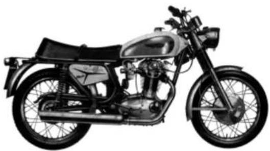
natural_image
Side profile illustration of a vintage motorcycle with black body, chrome engine, and front wheel (no text or symbols)MOTORCYCLE DUCATI 450 MARK 3 DESMO
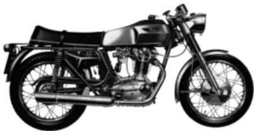
natural_image
Side profile of a vintage motorcycle with visible engine, wheels, and exhaust pipes (no text or symbols)STANDARD MODEL
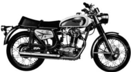
natural_image
Side profile illustration of a vintage motorcycle with visible engine and front wheel (no text or symbols)U.S.A. MODEL
| CAUSE | REMEDY |
| The spark gap between the electrodes of the sparking plug is too wide. | Adjust the gap to the proper width of about 0.8 mm. (0.0315"). |
| The sparking plug electrodes are dirty. | Clean the electrodes with a wire brush. |
| The contact breaker opening is excessive. | Readjust the exact opening of the contact which is 0.3 ÷ 0.4 mm. = 0.0118'' ÷ 0.0157'' (at a Ducati Servicing Garage). |
| The secondary winding of the coil is short-circuited or broken. | Change the coil (at a Ducati Servicing Garage). |
| The silencer is almost completely clogged-up. | Clean the silencer, to ensure the free discharge of the spent gases. |
INEFFICIENT ENGINE
| CAUSE | REMEDY |
| Irregular feed of petrol to the carburetor. | Clean the carburetor filter, the petrol cock filter and the petrol pipe. |
| Main jet partly clogged. | Clean the main jet by means of an air blast. |
| Carburetor butterfly valve does not open completely. | Readjust the valve travel by means of the adjustment screw of the carburetor Bowden cable (at a Ducati Service Garage). |
| The float needle does not close properly. | Clean out the carburetor and especially the needle seat (at a Ducati Servicing Garage). |
| Petrol of bad quality. | Empty the petrol tank and refill at a reliable garage. |
| The spark plug is not of the right type. | If the sparking plug overheats, you will have preignition, knocking and misses, especially at high revs. If the sparking plug remains too cold, you will have no ignition, because the electrodes will short-circuit. Use the right type of sparking plug; we advise the use of a plug having a thermal figure of 260 of the Bosch international scale. |
| The plug is loose in its adaptor. | Tighten the plug down well. A washer should always be placed between the sparking plug and its seating in the cylinder head. |
| The sparking plug cable sparks externally. | Change the cable or repair the insulation (at a Ducati Servicing Garage). |
MOTORCYCLE DUCATI 450 SCRAMBLER
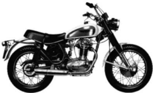
natural_image
Side view of a vintage motorcycle with chrome engine and front wheel (no visible text or symbols)STANDARD MODEL
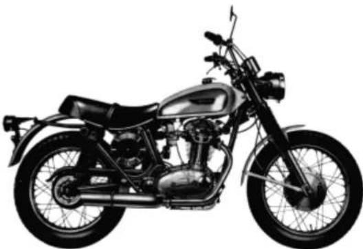
natural_image
Side profile of a vintage motorcycle with chrome engine and front wheel (no visible text or symbols)U.S.A. MODEL
A FOREWORD
The main goal of the present instruction booklet is to enable the owner of an over head cam-shaft DUCATI Motorcycle to use his vehicle in the best possible way.
The following notices are therefore only simple recommendations, suggestions, advices, and terms of reference, sufficient to enable anyone, having no experience or ignoring any special technical knowledge, to use his vehicle and to maintain it for a long time in perfect working condition.

CAUSE
The battery quickly discharges for a fault or an interruption in the recharging circuit.
REMEDY
Disjoin the wire from the terminal block of the battery.
Insert an amperometer in continuous current between the terminal clamp and the wire (possibly with central ).
— Insert the ignition key and let the engine turn, till attaining 6000 r.p.m.
The amperometer should show:
a) maximum current about 10 A, with completely discharged battery.
b1 minimum current about 1 A, with completely charged battery.
According to the battery load condition, you will obtain intermediate figures.
These tests must be carried out with switched out head-light.
Checking the Electrical System.
Make sure that all the bulbs are efficient.
1) With the lights switched out (during the day), the amperometer should read 0 at 1.100 r.p.m. approx.
2) With town lights switched on (during the night), the amperemeter should read 0 at 1.400 r.p.m. approx.
3) With the antidazzle lights switched on (during the night) the amperemeter should read 0 at 2,300 r.p.m. approx.
| CAUSE | REMEDY |
| The contact breaker points do not open. | Check the position of the fixed contact point (at a Ducati Servicing Garage). |
| The contact breaker arm is seized on its pivot. | Check movement between rocker arm and pivot and if necessary lubricate the pivot. |
| The contact breaker points are dirty. | Clean the contact breaker points with a rag damped in petrol. |
| The capacitor has broken down or is short circuited. | Change the capacitor (at a Ducati Servicing Garage). |
| Compression lacking. | Check if the sparking plug has been tightly screwed in, check the valves for gas-tightness and the tightness of the piston rings (at a Ducati Servicing Garage). |
| A valve spring is broken. | Change the broken sping (at a Ducati Servicing Garage). |
| Valve sticking. | Dismantle the valve, clean the valve stem and the bore of the valve guide, and make sure that the clearance between stem and bore does not exceed 0.08 mm. = (0.0032") (at a Ducati Servicing Garage). |
| The rocker adjuster is worn out. | Check again the clearance by fitting the adequate rocker shim on the valve stem end. |
| The battery is discharged. | Recharge the battery according with the instructions of page 49 (at a Ducati Servicing Station). |
DUCATI SERVICING GARAGE
It is advisable when taking the machine to a garage for repairs to ensure that the garage is a Ducati agent as the staff will have been specially trained and the garage will have been equipped with the necessary tools to carry out any repair required. They will also carry a full stock of genuine Ducati spares.
SPARE PARTS
It is absolutely necessary that each order for spare parts clearly states the following data:
1) The catalogue code of the spare part obtained from the Spare Parts Catalogue.
2) Serial number of the engine (when ordering spare parts of the engine).
3) Serial number of the frame (when ordering spare parts of the frame).
IDENTIFICATION NUMBERS
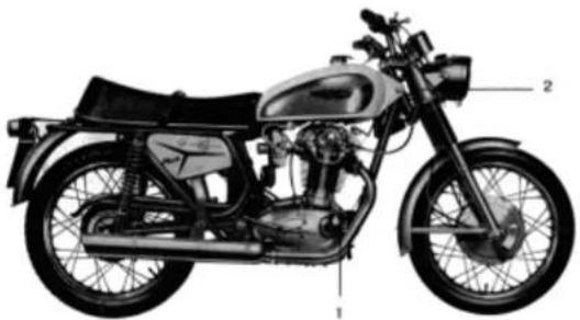
Every DUCATI over head cam-shaft motorcycle can be identified by its frame and engine serial number.
For the frame, the number is printed in the steering tube.
The engine serial number is stamped on the crankcase near the front connection between the engine and the frame.
natural_image
Side view of a vintage motorcycle with labeled parts (no text or symbols beyond labels)1 - Engine series
2 - Frame serial number
LOCATING AND REMEDYING FAULTS
The following list contains several of the most frequent faults which may arise and advice on remedying them.
ENGINE DOES NOT START EASILY
First of all, ascertain that there is enough petrol and that the cock is turned on (A=open; R=reserve). If these are in order, the fault may be one or more of the following:
| CAUSE | REMEDY |
| Petrol pipe is clogged. | Blow through it until the obstacle is removed. |
| Petrol filter dirty. | Dismantle the filter and clean the gauze by air blast. |
| Petrol cock filter is dirty. | Dismantle the filter and clean it by a blast of air through the gauze. |
| Carburetor float stuck. | Remove the float and clean out the float chamber (this should be done by a DU-CATI Servicing Garage). |
| Carburetor float leaking. | Change the float (at a DUCA-TI Servicing Garage). |
| Jet is clogged. | Remove the obstacle by a strong blast of air. |
| The cable of the ignition coil is broken or sparking externally. | Inspect the cable insulation for faults and if necessary change the cable at a DU-CATI Servicing Garage. |
| Defective sparking plug. | Change or clean the plug, making sure that the insulating core is not damaged, that there are no carbon deposits on the electrodes and that the spark gap does not exceed 0.8 mm. (0.0315"). |
natural_image
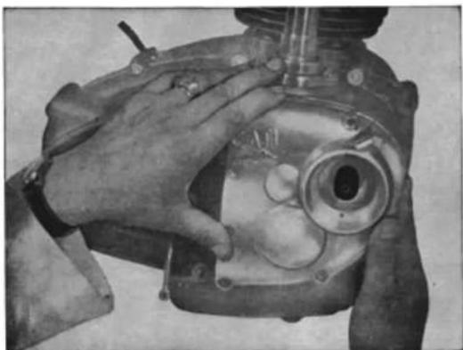
Close-up of a hand operating a mechanical device with a circular dial and internal components (no visible text or symbols)20 - Bush for fitting advance cover
PRECAUTIONS
to be followed during the initial running-in period
The modern engine construction calls for very close tolerances between moving parts. It is essential that care is exercised during the running-in period, a process which has already been started by the factory. The engine should never be over-revved or allowed to « slog » during this time and recommended maximum speeds in gears should be strictly observed.
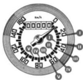
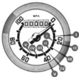
| DISTANCE TRAVELLED | MAXIMUM SPEED IN MILES AND KMS. PER HOUR | ||||
| In bottom speed | in 2nd speed | in 3rd speed | in 4th speed | in top speed | |
| Up to 300 miles | 16 | 22 | 29 | 36 | 40 |
| Up to 500 Km. | 25 | 36 | 48 | 56 | 64 |
| From 300 to 600 miles | 21 | 31 | 40 | 49 | 58 |
| From 500 to 1000 Km. | 34 | 50 | 64 | 79 | 90 |
It is advisable to change the oil first at 300 miles and then at 600 miles (with the engine warm). Re-adjust the tappets, fitting the rocker appropriate shim; tighten cylinder head and holding nuts, crankcase nuts and screws. Do not overtighten as damage may result in thread stripping or bolts breaking. Readjust contact breaker.
In order to ensure careful running-in the carburetor has been fitted with a distance piece which restricts the full use of the accelerator. After 600 miles this should be removed by your Ducati dealer.
Failure to comply with the above recommendations absolves the manufacturer from all liability of guarantee and any damage that may result.
natural_image
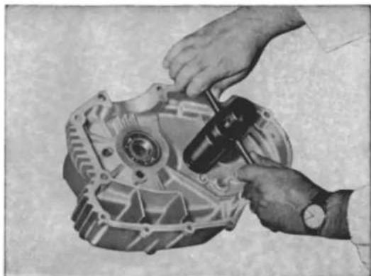
Close-up of hands assembling a mechanical component (no visible text or symbols)24 - Ball bearing puller
natural_image
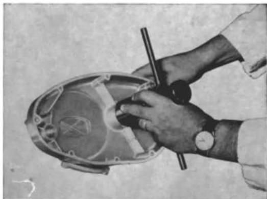
Close-up of hands using a tool to clean or inspect a mechanical component (no visible text or symbols)24 - Ball bearing puller
natural_image
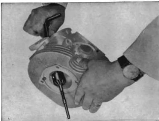
Close-up of hands assembling a mechanical component with a tool (no visible text or symbols)22 - Grinder for valve seats (one for inlet and one for exhaust)
natural_image
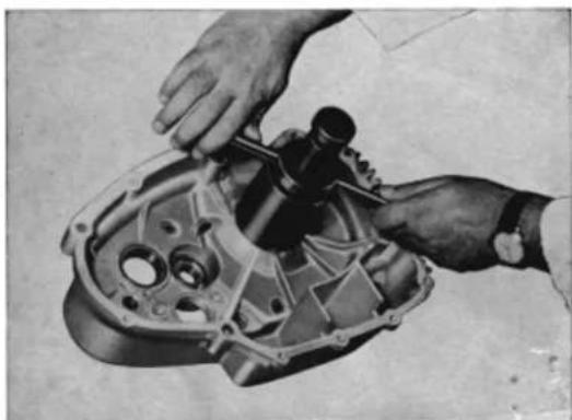
Close-up of hands assembling a mechanical component (no visible text or symbols)24 - Ball bearing puller
MAIN SPECIFICATIONS
natural_image
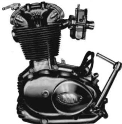
Technical illustration of a motorcycle engine with visible caliper, crankshaft, and internal components (no text or symbols)Note: The figure represents the engine of the 350 MARK 3
ENGINE
— Single cylinder, four strokes, with cylinder inclined forward 10^ from the vertical. The engine is supported by a cradle formed frame.
— bore: 74 mm. (2.9134") for the 250 cc. and 76 mm. (2.9921") for the 350 cc.;
— stroke: 57.8 mm. (2.2756") for the 250 cc. and 75 mm. (2.9527") for the 350 cc.;
— cylinder capacity: 248.6 cc. (15.1698 cu. in) for the 250 cc. and 340.2 (20.7544 cu. in) for the 350 cc.;
— compression ratio: 9:1 for the 250 SCR, 9.7:1 for the 250 MARK 3 and DESMO and 9.5:1 for the 350 cc.
— combustion chamber with hemispherical ceiling;
— cylinder barrel in light alloy, deeply finned and with inserted special cast-iron liner;
— connecting rod in special steel with big-end assembled on a cage roller bearing (crank pin) and little-end bushed to take the gudgeon pin;
— piston in light alloy, conical truncated, press-forged with skirt in one piece, with 3 piston rings, 1 of which is slotted oil scraper;
— cylinder head cast in light alloy and closely finned with inserted valve seats.
TIMING
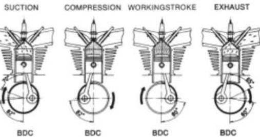
The timing system is provided with overhead valves, inclined at 80° timed by an overhead camshaft. The valves are made in special steel.
250 SCR
SUCTION
COMPRESSION
WORKINGSTROKE
EXHAUST
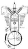
BDC
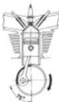
BDC
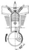
BDC
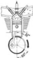
BDC
DATA
The timing data, with a clearance of 0.05 ÷ 0.10 mm. ( 0.0020'' ÷ 0.0039'' ) between the valves and the rockers are as follows:
| Valve | Opening ± 5° | Closing ± 5° |
| Suction | 27° before TDC | 75° after BDC* |
| Exhaust | 60° before BDC | 32° after TDC** |
* BDC - Bottom dead center.
** TDC - Top dead center.
natural_image
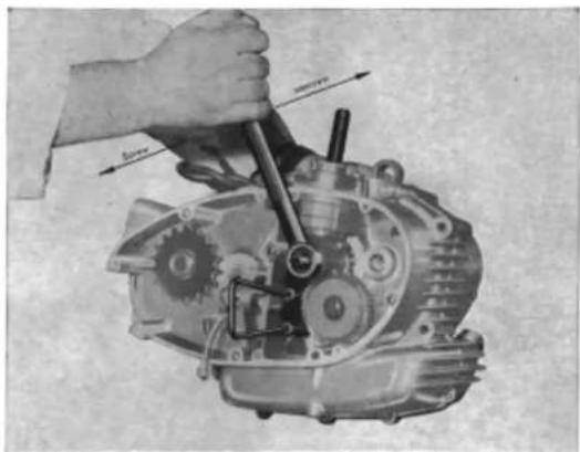
Mechanical assembly diagram showing a hand operating a gear mechanism with tool (no text or labels visible)18 - Tools to lock the main shaft tapered Z = 21 gear
natural_image
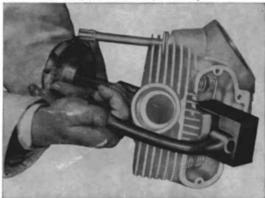
Close-up of a hand using a mechanical component to adjust internal components (no visible text or symbols)21 - Device for assembling and dismantling valves
natural_image
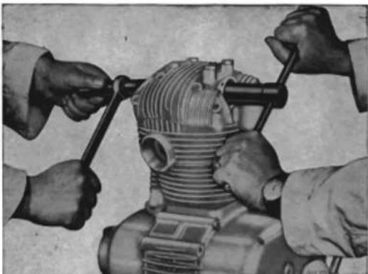
Close-up of hands operating a mechanical component with threaded pins (no visible text or symbols)15) Spanner to hold timing shaft
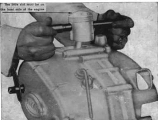
16-17 - Pins to fit and re-fit gudgeon pin
450 MARK 3 DESMO
Timing, with a clearance of 0.10 ÷ 0.15 mm. ( 0.0039'' ÷ 0.0059'' ) between the valves and the rockers are as follows:
| Valve | Opening ± 5^ | Closing ± 5^ |
| Suction | 70^ before TDC | 82^ after BDC * |
| Exhaust | 80^ before BDC | 65^ after TDC ** |
* BDC - Bottom dead center.
** TDC - Top dead center.
Adjustment
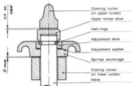
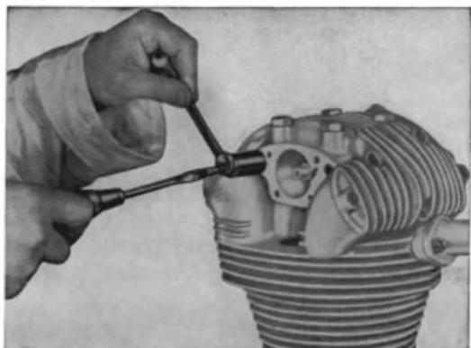
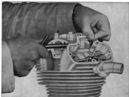
The tappets are adjusted by means of the appropriate rocker shim on the end of the valve stem.
Clearance
The working clearance between valves and rockers, when the engine is cold, is of 0.05÷ 0.10 mm. (0.0020"÷ 0.0039") for 450 Mark 3 and 450 Scrambler; for 450 Mark 3 Desmo clearance is of 0.10÷ 0.15 mm. (0.0039"÷ 0.0059") (upper rockers) while, and of 0 mm. (lower rockers) while.
natural_image
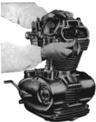
Close-up of hands assembling a mechanical engine component (no visible text or symbols)The clearance has to be adjusted and checked with a feeler gauge, after the said timing data have been controlled.
natural_image
Close-up of hands using a tool to adjust internal components of an engine cylinder (no text or symbols visible)11 - Extractor for rocker pin
natural_image
Close-up of hands assembling a mechanical engine cylinder (no visible text or symbols)14 - Pin for orienting washers and bushes when fitting rocker pins
natural_image
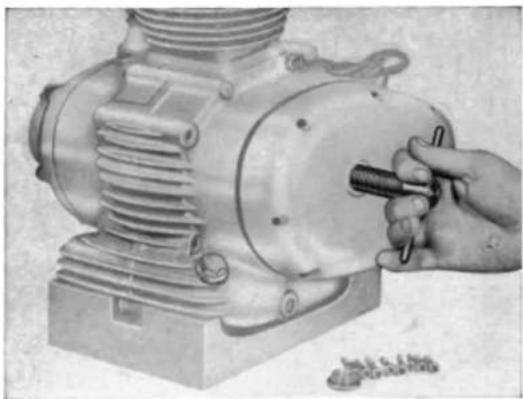
Illustration of a hand using a tool to adjust or install a mechanical component (no visible text or symbols)9 - Cover extractor on clutch side
natural_image
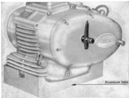
Illustration of an industrial electric motor with visible cooling fins and a labeled base (no text or symbols on the device itself)10 - Piston position indicator
Engine timing
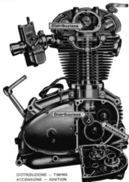
The timing gears in the crankshaft and on the camshaft, are provided with reference marks engraved on the toothed periphery. A point (.) for all the gears except that of the ignition coil which bears a line (|).
ATTENTION - The gear of the ignition coil has also a carved point (.), that in the 450 cc. Motorcycles has not to be taken into consideration.
The engine is timed when the above mentioned marks are disposed as indicated by the arrows in the following illustration.
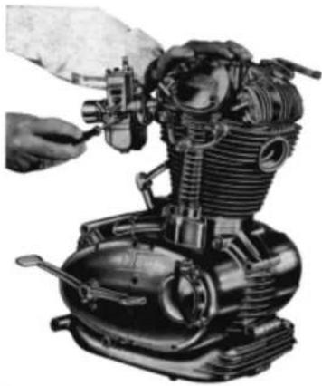
Adjustment of minimum air intake
natural_image
Black-and-white photo of a mechanical engine with visible gears and shafts, being adjusted by hand (no text or symbols)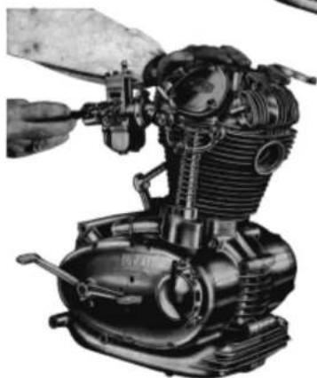
natural_image
Mechanical engine assembly with hand operating a valve (no visible text or symbols)Adjustment of the throttle
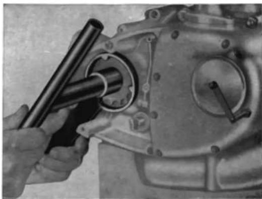
natural_image
Close-up of hands using a tool to adjust or install a mechanical component, no visible text or symbols6 - Wrench to hold the counter shaft sprockets
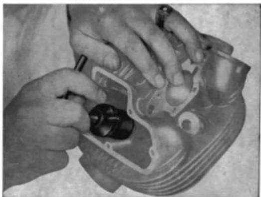
natural_image
Close-up of hands assembling a mechanical component (no visible text or symbols)8 - Clamp for lapping the valve seats
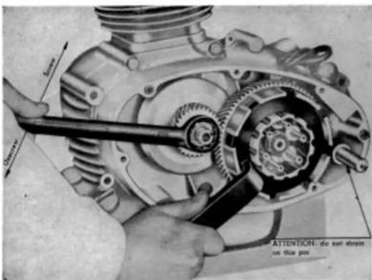
4) Spanner to secure the clutch housing
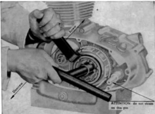
5) Spanner to secure the clutch drum
PETROL FEED
The petrol is fed to the carburetor by gravity. The carburetor is Dell'Orto with filter and cloth filter for 450 MARK 3, SCR, with horn for 450 DESMO.
| Models | Carburetor | Atomizer | Diffuser | Jet Max | Jet Min |
| 450 MARK 3 | VHB 29 AD | 265 T | 29 | 135 | 50 |
| 450 MARK 3 D | VHB 29 AD | 265 T | 29 | 145 | 50 |
| 450 SCR | VHB 29 AD | 265 T | 29 | 135 | 50 |
My 450 Mk3 Slide - 7454-60 Neddle - V7 Choke - 70
| Models | Petrol tank capacity it. | Taps number | Reserve it. |
| MARK 3 | 11 (imp.gal. 2.4197= USA gal.2.9059) | 2 | 1.6 (imp.gal. 0.35199= USA gal.0.4227) |
| SCRAMBLER | |||
| MARK 3 D | 13 (imp.gal. 2.8597= USA gal.3.4342) |
LUBRICATION
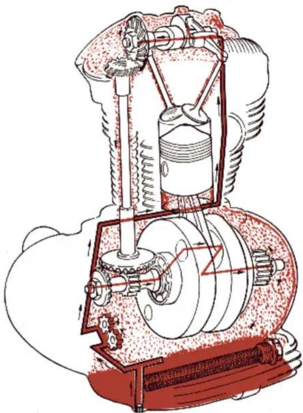
The engine is pressure lubricated, by means of a gear pump driven by the shaft; this pump takes the oil through a filter, from the lowest point of the crank-case which acts as an oil sump, and forces it through proper oil-ways, to all parts of the engine which have to be lubricated. The oil returns by gravity.
The sump capacity is of about 2.2 Kg. (4.850 lb) = lt. 2.5 (0.5499 imp. gal. = 0.6604 USA gal.).
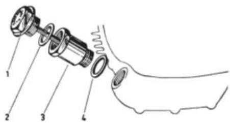
An Oil-filler with stick consisting of:
1) Stick-provided filler plug;
2) Sealing gasket;
3) Filler;
4) Sealing gasket;
allows the oil level measurement.
natural_image
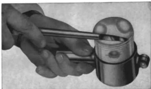
Close-up of a hand using a tool to press a mechanical component (no visible text or symbols)2 - Tool to grasp piston
natural_image
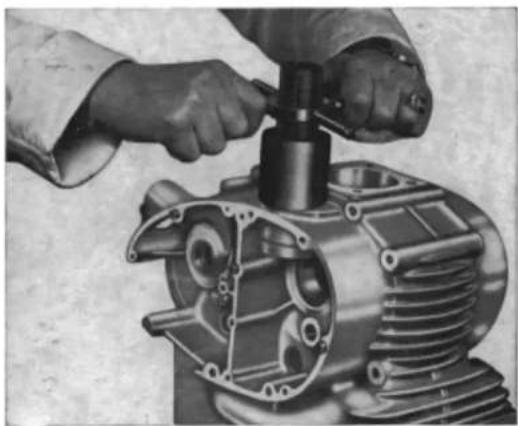
Close-up of hands assembling a mechanical engine component (no visible text or symbols)3 - Extractor for timing bearing holder bush
SERVICE STATION
TOOL EQUIPMENT DIRECTIONS FOR USE
natural_image
Illustration of a mechanical device with gears and components (no visible text or symbols)1 - Flywheel magneto extractor
natural_image
Cross-sectional diagram of an internal combustion engine showing piston, crankshaft, and housing components (no text or labels)The filler plug stick is marked by two notches in the spots where the oil level is respectively at its lowest and at its highest point.
The oil level is measured by just resting the plug on the filler.
— The lubricating system of the DUCATI motorcycles with over head cam-shaft engine is of the simplest and requires no special maintenance except the renewal of the oil level ( F.1 SUPERMOTOROIL 20W/40 or F.1 RACING SAE 40) each 500 Km. about 310 miles) and the total change of the oil, including the cleaning of the filter every about 2000 Km. (about 1240 miles).
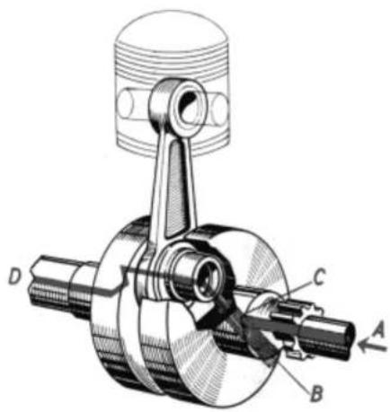
CENTRIFUGAL OIL FILTER INSERTED IN THE MAIN SHAFT
TOOL EQUIPMENT
LEGEND
1) Flywheel magneto extractor
2) Tool to grasp piston
3) Extractor for timing bearing holder bush
4) Spanner to secure the clutch housing
5) Spanner to secure the clutch drum
6) Wrench to hold the counter - shaft aprocket
7) Spanner for nuts with hollow hexagon ch. 5 (0.1968") or ch. 6 (0.2362")
B) Clamp for lapping the valve seats
9) Cover extractor on clutch side
10) Platon position indicator
11) Extractor for rocker pin
(4) Pin for orienting washers and bushes when fitting rocker pins
15) Spanner to hold timing shaft
17) Pins to fit and re-fit gudgeon pin
(8) To lock the main shaft tapered Z = 21 gear
a) with assembled cylinder head of dis
12) Spanner for devel gear Z = 28 (see 15) 30) Plus assembly sensors for pluses with h
20) Plug assembly spanner for plugs with hollow hexagon oh. 12 (0.4724)
(1) Device for assembling and disulfacing valves with Next (2) Grinder for valve costs into for inert and one for extorally
(2) Grinder for valve seals (one for inlet & T) Key for threaded pipe of exhaust pipe.
(2) Key for threatened IT
(26) Push for fitting advance cover
TOOLS FOR SERVICE STATION
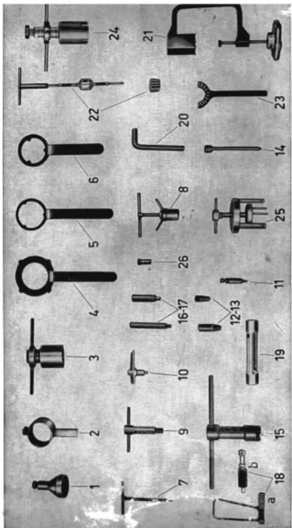
Note: The tools nrs. 12, 13 and 25 are deleted
How it works
The oil which is to be filtered, is brought to the filter through the pipe A; from here, the centrifugal force eliminates all the impurities (which are heavier than the oil), which accumulate all around the threaded plug B of the main shaft.
The filtered oil goes through the tube C to lubricate the big end, and through the duct D to lubricate the engine clutch housing gear.
COOLING
Cooling of the engine is achieved by close finning of both the cylinder and cylinder head.
IGNITION
The ignition is battery-coil.
The partial automatic advance ignition is:
| Advance with stopped engine | 0° |
| Amplitude of automatic advance | 28° |
| Total advance with engine running at 3.000 r.p.m. | 28° |
natural_image
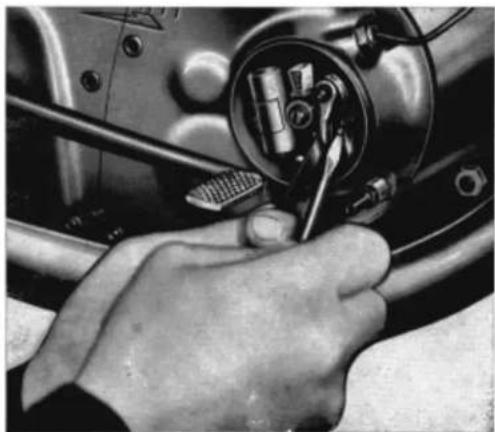
Close-up of a hand using a tool to adjust or install a mechanical component (no visible text or symbols)For setting up the ignition, see figure on page 14.
The clearance between the platinum plated contacts is of 0.3 to 0.4 mm. (0.0118" to 0.0157") and has to be checked by means of the feeler gauge (see figure on previous page).
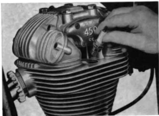
The ignition plug is a Marelli CW 260 N, or a similar model and is located on the left side of the top of the cylinder head.
When replacing the sparking plug make sure the angle of the plug, relative to the plughole, is correct otherwise there is a risk of stripping the thread in the cylinder head. Screw the plug lightly at first, then tighten it.
natural_image
Close-up of a hand adjusting a mechanical component with visible gears and shafts (no text or symbols)SERVICE STATION
HOW TO CHECK IGNITION SPARK ADVANCE
Check periodically the ignition spark advance (after the first 600 and, alter, every 1200 miles); be sure that the automatic device works properly, that it is well lubricated and that the springs are neither out of shape nor out of place.
(Fig. 1)
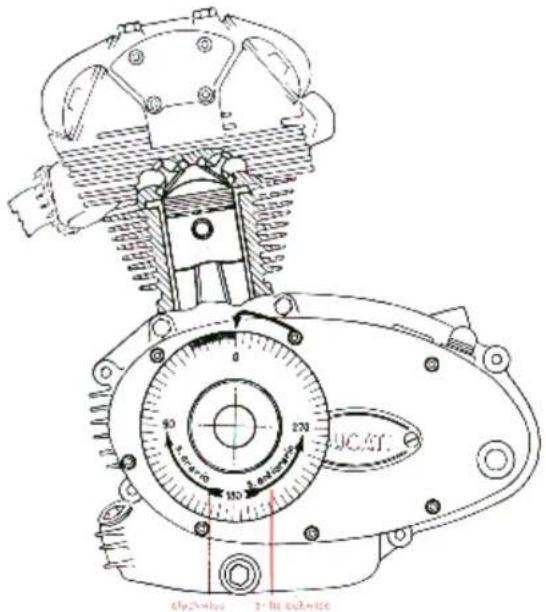
The rotary amplitude of the automatic advance must be 14° equal to 28° on the driving shaft. If you have any doubt, get it checked by a specialized workshop. To check the spark advance, proceed as follows:
In case the accumulators remain temporarily inactive, it is necessary to recharge the battery at least once each month, and each time the battery will be put in service.
INSTRUCTIONS FOR THE MAINTENANCE OF THE ELECTRICAL SYSTEM
In case of inspections or repairs, it is extremely important to know the working of the electrical system and to follow with care the scheme on page 34/1.
To avoid demagnetizing the regulator, be careful never to send electrical current (direct or alternate current) in the opposite direction.
Every inspection should be made with convenient Ohmmeters and Voltmeters.
To avoid ruining the efficiency of the electronic regulator, never run the engine without battery.
For no reason, the electronic regulator of current should be opened: if it does not work, send it to the CONCESSIONAIRES of DUCATI MECCANICA for replacement.
NOTICE! Battery shall be always mounted with the positive pole (+), red cable clamp, at the driver's right-hand side, and with, the negative pole (—), blue cable clamp, at the driver's left-hand side.
1/10 of the normal 10 hours capacity, for a maximum period of at least 10 consecutive hours.
Take care that during the charge the temperature of the electrolyte does not overpass 50°C (122°F).
The charge has to be interrupted:
a) when the above mentioned effective number of hours has elapsed, reckoning of course also the eventual interruptions;
b) in case of an intense ebullition in all the elements;
c) in case that for at least 3 consecutive readings at intervals of one hour each, the density of the electrolyte and the voltage of each element remain the same.
At the end of the charge, the electrolyte should have recovered the initial density, and the voltage of each element should arrive at a minimum of 2.7 Volts under charge, that is 8.1 Volts for a battery of 3 elements and of 16.2 Volts for a battery of 6 elements.
At this point the battery is ready to be put in service.
SUCCESSIVE CHARGES
The successive charges have to be made preferably with a current having an intensity in Amp. equal but not greater than 1/10 of the normal 10 hours capacity.
If during the charge the temperature, checked with a suitable thermometer immersed into the electrolyte would reach 50°C, (122°F), it will be necessary to reduce or to interrupt the charge until the temperature falls at least below 40°C (104°F).
The charge must continue until the density of the electrolyte results to be constant during 3 consecutive readings made at intervals of one hour each, and until the voltage reaches the value of 2.7 Volts for each element.
Never and for no reason refill the battery with sulphuric acid of whatever density. The refilling has to be made only with distilled water, chemically pure, taking care that the vessel used on this behalf be absolutely clean, to avoid the spoiling of the electrolyte by noxious substances and so compromise the efficiency of the battery.
1st. Remove the threaded plug which is at the driving shaft level, and fit a suitable timing chart (Fig. 1).
2nd. - Fit an indicator on one of the screws that secure the cover (Fig. 1).
3rd. - Bring engine to TDC of compression stage and set the indicator at « O » of the timing chart (Fig. 1).
4th. - Rotate the driving shaft clockwise for about a quarter of a turn.
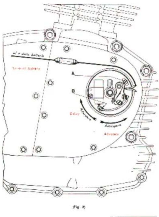
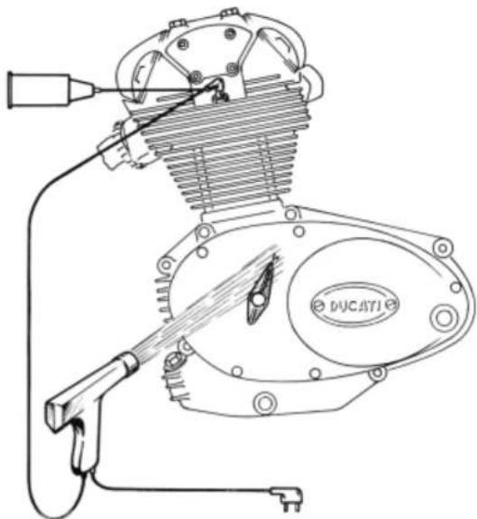
5th. - To the spring of the mobile part of the contact breaker connect a 6V.-3W. lamp in series with the + of the battery (Fig. 2). The lamp should light up.
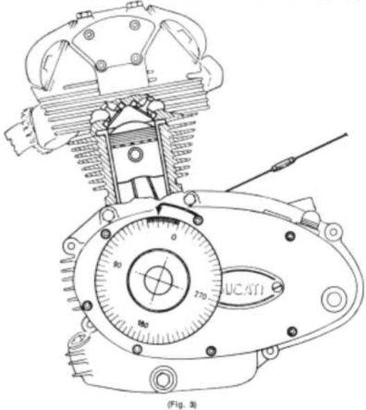
6th. - Rotate the driving shaft slowly, anticlockwise, till the light goes out or its intensity is lowered. At that very moment, the indicator should give on the goniometer the advance of 28°.
7th. - To be on the safe side, it is advisable to repeat the test.
8th. - If the reading should not tally with the requested numbers, then loosen the two screws (A and B) which secure the plate, and rotate it, advancing or delaying ignition until the right number of 28".
9th. - Bear in mind that if you let go dry the felt which lubricates the cam, the fibrous slipping block (that operates the opening of the moving part of the contact breaker arm), will tend to wear out, lowering thus the value of the gap.
IGNITION ADVANCE CONTROLLED BY STROBO LIGHT
1 - Let mount the advance control indicator 88713.0441 on the driving shaft flywheel side, after the plug 0400.49.090 has been removed.
2 - Insert the strobo light cable in the sparking plug.
3 - Let the engine run till 2,500 to 3,000 r.p.m. and send the strobo light on the reference (|) marked on the cover, clutch side.
4 - Check with the strobo light
The timing indicator must be lined up with the reference (1) (full advance); if it is not lined up, adjust the distributor, rotating anti-clockwise for the retarded timing, rotating clockwise for the advanced timing.
Parts needed for the check
— 1 advance control indicator 88713.0441 complete with screw and oil protection.
— The strobo bulb is not supplied.
Warning
The battery must always be preserved in a fresh but dry place. It is important to check frequently the level and the density of the electrolyte.
Never let the accumulators completely without charge. Keep always the plugs well closed and screwed down.
Clean always well the oxyde from the terminals and connections, and protect them with a thin layer of pure vaseline. Never use grease. The battery must always be preserved well cleaned and dry, especially the top part.
Electrolyte
The electrolyte consists of sulphuric acid of regular purity, diluted with distilled water, so that the density, referred to a temperature of 15^ C ( 59^ F.), corresponds to the following values:
| PLACE CONDITIONS | DENSITY OF THE ELECTROLYTE | Max. temperat. of the electrolyte during charge | |
| dry battery | charged battery | ||
| Temperate climate | 1.28+1.29 | 1.27+1.78 | 50°C (122°F) |
| Tropical climate | 1.21+1.22 | 1.20+1.21 | 60°C (140°F) |
The level of the electrolyte within the element must be at the same level of the antisplash gauze.
When all elements have been filled with the electrolyte, let the battery at rest for about 2 hours to allow the cooling of the plates.
A certain part of the electrolyte will be absorbed by the separators and by the plates, so that it will be necessary to add more electrolyte to establish the right level.
To check the electrolyte level use only glass sticks or ebonite.
First charge
Take down the breathers and connect the battery with a source of direct current, having an intensity equal to
— wash down the painted parts of the frame with water, using a sponge for washing and a shammy leather for drying;
— never use solvents, petrol, spirit or parafin, otherwise the paint will look flat;
— grease the chromium plated parts with vaseline and polish with shammy leather.
PROLONGED REST OF THE MOTORCYCLE
If the motorcycle has to be put at rest for several months, it is advisable to proceed as follows:
— clean the motorcycle thoroughly;
— empty the petrol tank;
— take out the battery and keep it efficient, as per instructions at page 49;
— squirt through the hole of the sparking plug several drops of oil into the cylinder and turn the engine by hand for several revolutions, distributing a thin oil film on the walls;
— put the motor upon a piece of wood, lifting the machine from the ground and empty the air out of the inner tubes;
— cover the machine with a canvas, or water-proof cover.
INSTRUCTIONS FOR THE FIRST CHARGE AND FOR THE MAINTENANCE OF THE BATTERY
Battery SAFA 3L3, with free acid, dry charge.
Type
— tension . . . . . . . . . 6 V
— Capacity at 20 hours . . . . 13.5 Ah
— Capacity at 10 hours . . . . 12 Ah
— Normal charging current . . 1.2 Amp.
— Max. recharging current . . . 2 Amp.
— External dimensions . . . . 120 x 90 x 165 mm. = 4.7244"x3.5433"x6.3960"
natural_image
Technical line drawing of a motorcycle engine assembly with visible components and tool path (no text or symbols)STARTING
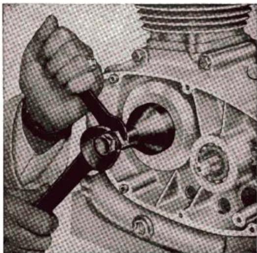
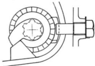
The kick-starter is located on the left hand side of the engine. In the case the started unit is refit, it is indispensable to carry it out as shown in the figure aside.
natural_image
Technical line drawing of a mechanical assembly with no visible text or symbolsTRANSMISSION
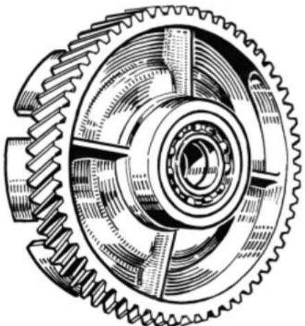
The transmission components comprise a clutch and a gear box. The clutch is of the multiple plate type with steel and phenol resin disks. It turns in an oil bath and is mounted on the primary shaft on the gear box.
The clutch housing, made of special wear resisting steel iron, turns on two inner bearings which are set at an adequate distance. It is lubricated together with the engine sprocket as already explained in the paragraph of the centrifugal filter.
This system ensures smooth movement, solidity and long wearing; it has been fitted and tested.
The clutch is operated by a handlever placed on the left hand side of the handlebar.
The transmission between the engine and the primary
natural_image
Technical line drawing of a mechanical gear assembly (no text or symbols)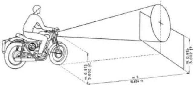
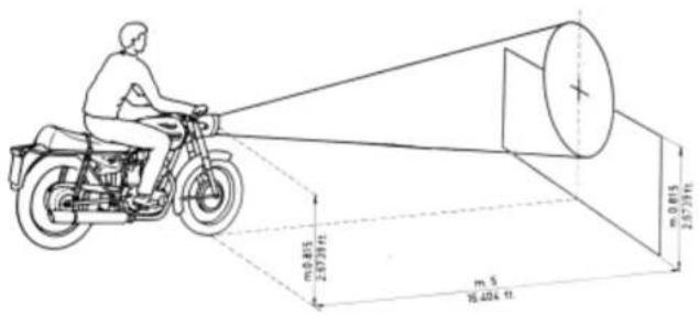
— trace a cross in the intersections between the optic axis and the wall, that it is at a height of 0.915 meter (ft. 3.002) from the ground, for SCR and 0.815 meter (ft. 2.6739) for MARK 3 and DESMO.
— when the depthlight is lighted up, the cross must be in the center of the circular light-beam hitting the wall;
— to rectify the alignment of the headlamp, operate by means of the two fixing screws of the headlamp on the front fork.
OVERALL CLEANING
The motorcycle should be washed and cleaned periodically, according to the length of time it has been used and the state of the road.
— Clean the engine with parafin and wipe it dry with a clean rag;
HEADLAMP ALIGNMENT
It is advisable to check periodically the alignment of the headlight as follows:
— place the motorcycle at a distance of 5 meters (ft. 16.404) from a bright wall;
— make sure that the ground be even and that the optic axis of the headlamp be perpendicular to the wall;
— the motorcycle with its rider must rest on the wheels, not on the central stand;
shaft of the gearbox is obtained by means of gears and the reduction ratio is:
2.111 to 1.
The gearbox is mounted in the crankcase; the gears for the 5 speed gearbox are constantly meshed and are operated by a foot pedal.
The transmission ratios of the gears are the following:
— in bottom gear 1 to 2.46
— in second gear 1 to 1.73
— in third gear 1 to 1.35
— in fourth gear 1 to 1.10
— in top gear 1 to 0.97
The transmission between the gearbox and the rear wheel is made by means of a chain and the speed ratio is:
2.666 to 1 for 450 MARK 3 and DESMO, 2.917 to 1 for 450 SCR.
FRAME
The frame of the DUCATI 450 is of a very smart and modern design, is manufactured with high tensile steel and is of the central girder type.
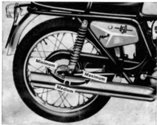
SUSPENSION
The front suspension is composed by the telescopic-hydraulic long-stroke fork, with steering stop.
DUCATI model for 450 MARK 3 and DESMO: each fork leg contains 100÷110 cu. cm. (cu. inch. 6.1025 to 6.7127) of F.1 oil. SHOCK ABSORBER
MARZOCCHI model for 450 SCR:
Each fork leg contains 180÷185 cu. cm. (cu. inch 10.98 to 11.29) F.1 ROTRA ATF oil., for hydraulic controls viscosity 3-4 Engler at 50°C.
The rear suspension consists of a robust hinged for with double action hydraulic differentiated load dampers (shock-absorbers), which can be adjusted for three different loads: Minimum - Medium - Maximum.
In these machines the fork fulcrum-spindle is fixed to the frame while the fork with bronze bush rotates on it. This gives the machine greater solidity and stability.
WHEELS
The wheels are of the spoke type with rims as follows:
| Model | Wheel Rim | Wheel rim size | ||
| Material | Profile | Front | Rear | |
| 450 MARK 3 | Steel | Normal | 18 × 212 | 18 × 212 |
| 450 MARK 3 D | Steel | Normal | 18 × 212 | 18 × 212 |
| 450 SCRAMBLER | Steel | Normal | 19 × 212 | 18 × 3 |
The front wheel has a detachable spindle.
The rear wheel has a special cushion drive.
Tyres and pressures are as follows:
| MODEL 490 | Front wheel | Rear wheel | ||
| Tyre | Pressure | Tyre | Pressure | |
| MARK 3 and DESMO | 2.75-18 ribbed supersport | 2.25 Kg/cm ^2 (32,01 lb/sq. inc.) | 3.00-18 grooved supersport | 2.25 Kg/cm ^2 (32,01 lb/sq. inc.) |
| SCRAMBLER | 3.50-19 grooved | 2.25 Kg/cm ^2 (32,01 lb/sq. inc.) | 4.00-18 grooved | 2.25 Kg/cm ^2 (32,01 lb/sq. inc.) |
EVERY 1500 Km (about 930 miles)
— Lubricate the speedometer drive with F.1 GREASE 30.
EVERY 2000 Km (about 1240 miles)
— Change the oil in the crankcase draining it while the engine is hot, make sure that the oil drains off completely.
— Remove the carburetor oil filter and wash it by blast of compressed air, in order to remove all impurities from the cloth.
— Clean out the carburetor float chamber, the main jet and the idle jet.
— Readjust the clutch because the wear on its linings might otherwise cause slip.
— Lubricate the hinge of the rear fork.
— Dampen with 2 drops (not more) of thin mineral oil the lubricating wick of the contact breaker cam.
— Tighten uniformly the nipples of the spokes and check whether the screws and the nuts of the wheels have been firmly tightened.
EVERY 10000 Km (about 6200 miles)
— Unscrew plug B of the crankshaft (see pages 22-23) and clean the hollow part.
— Tighten again the plug in its seat, smearing some paint to avoid the plug be unscrewed during operation. To clean, it is sufficient to remove the engine cylinder.
EVERY 20000 Km (about 12400 miles)
— Dismantle the exhaust pipe and the cylinder, in order to remove the carbon deposits on the cylinder head and on the piston (this should be done by a Ducati Servicing Garage).
MAINTENANCE
On good maintenance depends the good condition of the motorcycle.
By following these fundamental rules you can avoid serious trouble and obtain an excellent performance from your motorcycle.
The operations to be carried out are subdivided in accordance with the order on which depends the mileage run by the motorcycle. The recommendations which follow are, of course, merely indicative, because lubricating, checking and adjustments depend also on the nature of the road, the seasonal temperature, the length of the intervening period.
EVERY 500 Km (about 310 miles)
— Restore the oil-level in the crankcase;
— Check the tyre pressure with a pressure-gauge;
— Tighten the cylinder head holding down bolts;
— Readiust the brakes;
— Check the clearance between valves and rockers placing the appropriate rocker shim on the valve stem end, letting the clearance at the values reported at page 16.
EVERY 1000 Km (about 620 miles)
— Check and adjust the distance between the sparking plug electrodes to about 0.8 mm (0.0315") and clean them with a small wire brush and some petrol;
— Clean the contact breaker platinum plates with a rag damped in petrol and check the distance between the platinum plates, whose opening should be 0.3 to 0.4 mm (0.0118" to 0.0157");
— Check the clearance between valves and rockers as mentioned in the above paragraph.
BRAKES
The brakes are of the expanding type with two brake-shoes, — hand operated the front and pedal operated the rear — with finned brake drums of large diameter width, and with non fade brake linings.
The diameter of the front brake drum is 180 mm (7.0866"), the diameter of the rear drum is 160 mm (6.2992").
ELECTRICAL SYSTEM
The lighting is provided by a storage battery which is re-charged by the DUCATI flywheel alternator and electronic current regulator.
The head-lamp APRILIA of large diameter carries 3 lights. A Km-speedometer CEV with dial of 180 for MARK 3 and DESMO and 160 for SCR or a milespeedometer with dial 150, for MARK 3 and DESMO and 120 for SCR all with luminous dial is incorporated in a case fixed to front fork. Another case contains the revolution indicator for 450 MARK 3 and DESMO and on request for 450 SCR. The 3-way switch for the light control is situated on the head lamp. A removable key placed on the headlamp provides the contact for the ignition. By removing the key the engine is stopped.
Alongside the lefthand grip of the handlebar is the switch for the diplight, the antidazzle light, and the button for the horn.
In the normal position on the rear mudguad are placed the number-plate carrier, the rear light, the reflector, the numberplate lighting the stop-light and side lights (these on request).
When the engine is stopped, the electrical current for the position lights (town light and tail light) is provided by a free acid cell storage battery SAFA, mod. 3L3, of 6V-13.5 Ah; the charge is maintained by means of the flywheel alternator and electronic regulator.
IMPORTANT:
It is not at all possible to run the engine without battery as there would be no excitation to the rectifier. Actually the engine can be started only if the battery voltage exceeds 4 volts: if the voltage is below 4 volts (Battery fully down) the engine does not run.
When the engine is running, the battery cables must absolutely not be detached, as the electronic rectifier would inevitably be damaged.
ADVANTAGES OF THE ELECTRICAL SYSTEM
The electrical system with electronic regulator of current offers real advantages in comparison with the system employed till now.
The advantages can be summarised as follows:
1) Regulation of the automatic charge.
2) There are no electrical contacts with the regulator and therefore there is a greater surety in the working.
3) Simplified commutator system which is limited to the sole lights section.
4) Protection of the electrical system on 3 fuses and then, possibility to briefly locate the eventual breakdown and to allow the remaining part of the equipment to be operative: the fuse (17) protects the equipment of the front and rear parking lights; the fuse (19) protects the equipment of the head light (dazzling and antidazzling); the fuse (18), the horn and the stop indicator (see the electrical scheme).
5) Greater simplicity of operation and wiring.
WIRING SYSTEM OPERATION
1) Key inserted:
the machine can be run.
The white ignition light lights up till the engine stops.
The battery is conveniently recharged.
A good motorcyclist will make use of the controls intelligently and at the right time. When riding uphill and the engine tends to slow down, change to a lower gear at once; do not "hang on" to a higher gear when the effort required from the engine advises to use a lower gear.
When the engine turns at a low number of revolutions, do not accelerate its turning at once: thus you avoid any oversupply of fuel and too harsh drive to the transmission.
The clutch should not be held long disengaged with a gear engaged, because the clutch plates will become overheated, causing rapid wear by friction.
Except in case of emergency, never use the brakes brutally when you are already near behind the obstacle, but throttle down the engine in right time and then make use of the brakes.
Bear in mind that insufficiently inflated tyres are detrimental to the roadholding qualities of the motorcycle, cause a greater tyre wear and lower efficiency.
STOPPING THE MOTORCYCLE
To stop the engine, close the throttle completely (the engine will then act as a gentle brake) disengage the clutch and put the gear pedal in neutral. A slight use of the brakes will then stop the motorcycle.
To stop the engine pull out the contact key of the switch placed on the headlamp.
one-eighth of its travel, pull the valve-lift lever in models MARK 3 and SCR and thrust the kickstarter energically downward leaving the valve-lift lever before completing the travel in models MARK 3 and SCR after inserting wrench into the commutator placed on head lamp and rotating it clockwise.
If the engine does not start repeat this operation, varying at the same time more or less the opening of the throttle by means of the handlebar grip. Once the engine is started, bring air control lever to its former position (anticlockwise rotation), do not race it immediately, especially when the engine is cold, but before accelerating the engine let the lubricating oil warm up to facilitate its circulation throughout the engine, so as to reach all moving parts.
RIDING AWAY AND RUNNING OF THE MOTORCYCLE
With the engine running, disengage the clutch and, using your heel, push down the rear arm of the gearchange level. When this lever is left to itself it returns to its original position. With this move the bottom gear is now engaged. Now turn the rightand grip little by little and release gradually your hold on the clutch lever; the motorcycle begins slowly to go under way. With the clutch lever completely released let the motorcycle increase its speed until about 15/20 Km/h (9-12 m.p.h.). To pass now from bottom gear into second gear, turn back right-hand grip fully and quickly; and after having disengaged the clutch follow up at once by pressing down the front arm of the gearchange lever, with the toe of your shoe. Now turn forward the righthand grip again, releasing at the same time the clutch lever. Similar operations are carried out in order to change from second gear into third gear, from third gear into fourth gear and from the fourth to the top gear.
To change down from a high gear to a lower one, operate as follows: close the throttle, disengage the clutch, accelerate the engine momentarily, thus synchronizing the gear about to be engaged, engage the lower gear and then let go off the clutch control.
commutator:
position 0 - lights switched out
position 1 - switched on the rear and front parking lights as well as the green warning light.
position 2 - projector light does not light commutable in dazzling and anti-dazzling lights.
the battery charge is well-balanced in all conditions.
(in the high beam, the red warning light lights)
the horn is operating
the stop indicator is operating
2) Key not-inserted:
the machine cannot be run
the white warning light does not light
commutator:
position 0 - lights switched out
position 1 - switched on the rear and front parking lights as well as the green warning light.
the battery cannot be charged.
position 2 - switched on projector light
The connection between the electronic regulator of current and battery is cut-out.
The horn does not operate.
The stop light indicator does not operate.
CONTROLS
As mentioned in the foregoing paragraph, alongside the left hand fixed handlebar grip will be found the two switches for the dip light and the antidazzle light, the button for the horn, the hand operated clutch lever, the valve-lift lever.
The righthand handlebar grip rotates for accelerating and decelerating the engine. In front of the grip is placed the operating lever for the front brake which operates the front stoplight and above grip is located the little air-regulating control lever.
Near the left hand footrest is placed the rear wheel brake lever which also operates the back stoplight and the kick-start. Alongside the right hand footrest is the double lever for the gear change.
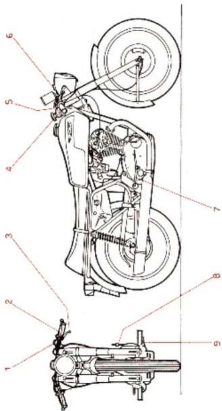
LEGEND
- Air regulating control lever
- Front brake control lever
- Charge double lever
- Kickstarter
- Rear brake control over
1 - 2 way switches for tip light and antidazole light, and button for horn
2 - Clutch control level
3 - Value lift control level
4 - Rotating throttle control grip
HOW TO USE THE 450 MOTORCYCLES
FILLING UP AND STARTING THE ENGINE
Before starting the engine make sure that there is sufficient petrol in the tank, for the distance you wish to travel. See that the petrol tap is on and that the engine lubricating oil is at the right level.
For the lubrication it is advisable to use 📄F.1 SUPERMOTOROIL 20 W/40 or 📄F.1 RACING SAE 40.
Having refuelled and checked the oil, see that gear lever is in neutral position and press down the carburetor tickler to ensure the correct level of petrol in the float chamber. Pull forward (clockwise rotation) air control lever. Now, after having inserted the contact-key into its place on the headlamp and turned it clockwise, turn the righthand handlebar grip (accelerator) for about
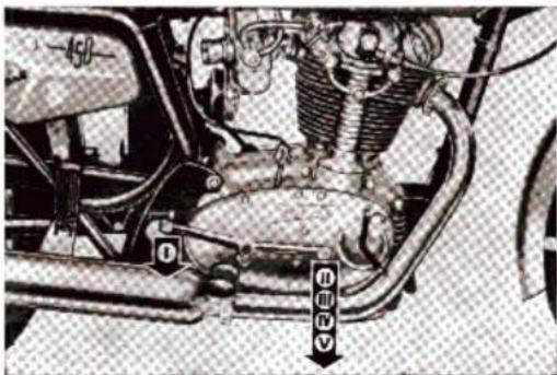
On the right side of the 450 MARK 3, is the air cleaner for the carburetor for the quiet air inlet. A proper box serves for the same purpose in 450 scr.
In the inlet duct of the carburetor, is the engine breather which sends oil vapours to the valves for their lubrication.
The battery is located between the two boxes in the models MARK 3 and DESMO.
MAX POWER AND CONSUMPTION AND DISTANCE
Max power
IMPORTANT: Do not exceed, in every gear, the maximum revolutions of the motor as shown here below for each model.
The non-observance of what above mentioned releases DUCATI MECCANICA from any responsibility, should eventual inconveniences occur in the motor.
| MODEL | r.p.m. max. |
| 450 MARK 3 | 6000 + 6500 |
| 450 MARK 3D | 6500 + 7000 |
| 450 SCR | 6200 + 6500 |
Fuel Consumption petrol SUPERCORTEMAGGIORE
| MODEL 450 | At an economical speed of | For 100 Km. It. | M/imp. gal. | M/U.S. gal. | |
| Km/h | M/h | ||||
| MARK 3 | 85÷90 | 63÷56 | 5.2 | 54 | 45 |
| MARK 3 D | 85÷90 | 53÷56 | 5.7 | 49 | 41 |
| SCR | 65÷70 | 40÷44 | 5 | 56 | 47 |
Maximum distance of cruising with one tankful:
| MODEL 450 | Km. | Miles |
| MARK 3 | 211 | 131 |
| MARK 3D | 228 | 142 |
| SCR | 220 | 137 |
SADDLE
The motorcycle is provided with a wide and comfortable saddle.
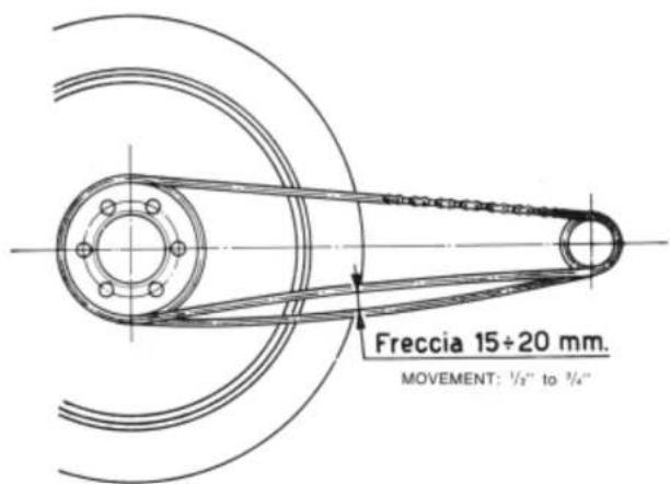
ADJUSTING OF THE CHAIN TENSION
For the correct chain adjustment up and down movement should be no more than 12 " to 34 ".
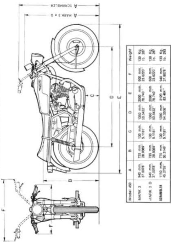
OVERALL DIMENSIONS AND WEIGHT
TOOL BOX
A large tool box of ample capacity is placed under the saddle at the left side of the rider and contains the spanners' and the tools supplied with the motorcycle for the normal inspections of the engine, which can be executed by the rider himself, only for the MARK 3 and DESMO models.
For the Scrambler model the cloth toolbag is supplied separately.
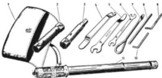
1 - Tool bag
2 - Double box spanner 19-22 (0.7480"—0.8661")
3 - Double box spanner 21 for hexagon 14 (0.8268" — 0.5512")
4 - Tyre lever
5 - Hexagon spanner 14 with tyre puller (0.5512")
6 - Double hexagon spanner 10-11 (0.3937"—0.4331")
7 - Screw driver
8 - Tommy-bar for box spanner 21-22 (0.8268"—0.8661")
9 - Spanner for hollow hexagon 6 (0.2362")
10 - Spanner for hollow hexagon 5 (0.1968")
11 - Tyre inflator
- DUCATI
- GUARANTEE CARD
- Dear Sir,
- A FOREWORD
- CAUSE
- REMEDY
- Checking the Electrical System.
- DUCATI SERVICING GARAGE
- SPARE PARTS
- IDENTIFICATION NUMBERS
- LOCATING AND REMEDYING FAULTS
- ENGINE DOES NOT START EASILY
- PRECAUTIONS
- ENGINE
- TIMING
- SCR
- DATA
- Adjustment
- Clearance
- Engine timing
- PETROL FEED
- LUBRICATION
- TOOL EQUIPMENT
- LEGEND
- How it works
- COOLING
- IGNITION
- HOW TO CHECK IGNITION SPARK ADVANCE
- INSTRUCTIONS FOR THE MAINTENANCE OF THE ELECTRICAL SYSTEM
- SUCCESSIVE CHARGES
- IGNITION ADVANCE CONTROLLED BY STROBO LIGHT
- Parts needed for the check
- Warning
- Electrolyte
- First charge
- PROLONGED REST OF THE MOTORCYCLE
- INSTRUCTIONS FOR THE FIRST CHARGE AND FOR THE MAINTENANCE OF THE BATTERY
- Type
- STARTING
- TRANSMISSION
- OVERALL CLEANING
- HEADLAMP ALIGNMENT
- FRAME
- SUSPENSION
- WHEELS
- EVERY 1500 Km (about 930 miles)
- EVERY 2000 Km (about 1240 miles)
- EVERY 10000 Km (about 6200 miles)
- EVERY 20000 Km (about 12400 miles)
- MAINTENANCE
- EVERY 500 Km (about 310 miles)
- EVERY 1000 Km (about 620 miles)
- BRAKES
- ELECTRICAL SYSTEM
- IMPORTANT:
- ADVANTAGES OF THE ELECTRICAL SYSTEM
- WIRING SYSTEM OPERATION
- STOPPING THE MOTORCYCLE
- RIDING AWAY AND RUNNING OF THE MOTORCYCLE
- commutator:
- 2) Key not-inserted:
- CONTROLS
- HOW TO USE THE 450 MOTORCYCLES
- FILLING UP AND STARTING THE ENGINE
- MAX POWER AND CONSUMPTION AND DISTANCE
- SADDLE
- ADJUSTING OF THE CHAIN TENSION
- TOOL BOX
Marque : DUCATI
Modèle : 450 Mark 3 (1970)
Catégorie : Moto