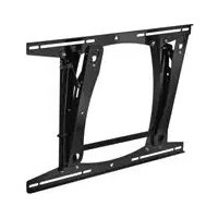
PLP2000B - Support écran plat Chief - Notice d'utilisation et mode d'emploi gratuit
Retrouvez gratuitement la notice de l'appareil PLP2000B Chief au format PDF.


| Type de produit | Support écran plat |
| Marque | Chief |
| Modèle | PLP2000B |
| Catégorie | Support mural pour écran plat |
| Compatibilité VESA | 200x200 mm à 400x400 mm |
| Charge maximale | 45 kg |
| Inclinaison | -5° à +15° |
| Rotation | ±90° (mode portrait) |
| Matériau | Acier à haute résistance |
| Couleur | Noir |
| Dimensions du panneau mural | 600 x 400 x 50 mm |
| Dimensions de la plaque écran | 500 x 300 x 20 mm |
| Poids du produit | 5 kg |
| Alimentation | Aucune (support mécanique) |
| Garantie | 2 ans |
| Contenu de l'emballage | Support mural, plaques écran, kit de vis, notice |
| Entretien et nettoyage | Essuyer avec un chiffon doux et sec |
| Sécurité | Ne pas dépasser la charge maximale ; vérifier l'ancrage au mur |
| Pièces détachées et réparabilité | Vis de rechange disponibles ; structure monobloc non réparable |
| Informations générales | Support professionnel pour écrans plats de taille moyenne à grande |
FOIRE AUX QUESTIONS - PLP2000B Chief
Questions des utilisateurs sur PLP2000B Chief
0 question sur cet appareil. Repondez a celles que vous connaissez ou posez la votre.
Poser une nouvelle question sur cet appareil
Téléchargez la notice de votre Support écran plat au format PDF gratuitement ! Retrouvez votre notice PLP2000B - Chief et reprennez votre appareil électronique en main. Sur cette page sont publiés tous les documents nécessaires à l'utilisation de votre appareil PLP2000B de la marque Chief.
MODE D'EMPLOI PLP2000B Chief
INSTALLATION INSTRUCTIONS
PLP Series Wall Mount
The PLP Series wall mount accommodates large flat screens weighing up to 200 lbs (90.72kg). The teardrop holes in the mount allow for quick connect/disconnect of the screen, thus simplifying installation and maintenance processes.
The top and bottom mounting brackets are adaptable to supporting framework with wood studs that are 16" on center or 24" on center.
The mount has integrated lateral shift, allowing for four different mounting options. For dual wood studs 16" on center, the lateral shift is ± 4.5 inches. For dual wood studs 24" on center, the lateral shift is ± 0.5 inches.
The display can be pulled and tilted by hand into any position in the zero-to-15 degree tilt range and remain stationary.
The bottom of the mount pulls forward 4" from the wall and locks into place for installation of cable connections.
The mount also uses Chief's exclusive Q-Latch™ mounting system, which offers quick connect/disconnect display mounting. The display is secured to the mount with a latching flag. For additional security, you can lock the latching flag in place by adding a padlock.
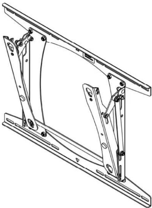
PLP Series
!IMPORTANT: If the installation of this product requires OSHPD seismic approval, refer to OSHPD pre-approval documents and drawings before beginning installation. OSHPD documents and drawings are available at www-chiefmfg.com, and located on the product information page for the mount.
BEFORE YOU BEGIN
- CAUTION: To prevent damage to your monitor and PLP, which could affect or void the Factory warranty, thoroughly study all instructions and illustrations before you begin to install the mount. Pay particular attention to the Warnings and Cautions in this document.
- The mount is designed to be installed using wall studs or supporting framework. The fasteners used to anchor the mount must be capable of supporting five times the total weight of the equipment.
• The maximum weight to be installed on the PLP Series wall mount is 200 lbs (90.72kg). - If you have any questions about this installation, contact Chief Manufacturing at 1-800-582-6480 or 952-582-6480.

IMPORTANT WARNINGS and CAUTIONS!
| WARNING | A WARNING alerts you to the possibility of serious injury or death if you do not follow the instructions. |
| CAUTION | A CAUTION alerts you to the possibility of damage or destruction of equipment if you do not follow the corresponding instructions. |
| • WARNING | Improper installation can result in serious personal injury! Make sure that the structural members can support a redundant weight factor five times the total weight of the equipment. If not, reinforce the structure before installing the mount. |
| • WARNING | Be aware of the potential for personal injury or damage to the equipment if it is not installed correctly. Consider the weight of the mount without the display. |
| • WARNING | The installer is responsible for verifying that the display to which the wall mount is fastened will safely support the combined load of all attached components or other |
DIMENSIONAL DRAWING


NOTE: CUSTOM INTERFACE BRACKET NOT SHOWN. THE CUSTOM INTERFACE BRACKET NEEDED FOR YOUR DISPLAY WILL ADD BETWEEN 1/2" AND 2" IN DEPTH AND MAY AFFECT LOCATION OF DISPLAY ON THE MOUNT.
SEE PSB-XXXX DRAWING ALSO.
CONTENTS
DIMENSIONAL DRAWING 3
TOOLS REQUIRED FOR INSTALLATION....4
PARTS LIST 4
PLP INSTALLATION 5
Select Mounting Location 5
Mount the PLP 6
ATTACH PSB TO THE DISPLAY....7
INSTALL THE DISPLAY....7
REMOVE THE DISPLAY....7
TILT ADJUSTMENT 8
CABLE CONNECTION 8
PARTS LIST
Prior to assembly, unpack the carton completely. Verify contents listed in Table 1 and Figure 1.
Read installation instructions completely. If you are missing any of the listed parts, contact Customer Service at: 1-800/582-6480.
Table 1. Parts List
| REF | DESCRIPTION | QTY |
| 10 | PLP Series Wall Mount | 1 |
| 20 | BOLT, Lag, 5/16" x 2-1⁄2" | 4 |
| 30 | WASHER, 5/16" | 4 |
TOOLS REQUIRED FOR INSTALLATION
- Drill and drill bit set
- Socket wrench set
NOTE: Other tools may be required depending on your method of installation.


PLP INSTALLATION
Perform the following procedures to mount the PLP.
Select Mounting Location
To select the mounting location, do the following:
WARNING: It is the responsibility of the installer to verify that the wall to which the mount is anchored will safely support the combined load of all attached components and equipment.
- Determine the exact mounting location to install the wall mount prior to installation, keeping in mind the screen size.
NOTE: Mount the PLP on dual wall studs or some other equivalent supporting framework that is vertical or horizontal.
- Using a stud sensor, locate the two wood studs where you will mount the PLP as follows:
- Refer to Figure 3 for wood studs that are 16" apart on center.
OR
- Refer to Figure 4 for wood studs that are 24 apart on center.
-
Using a nail as a temporary hook, hang the mount on the wall using the triangular hole located in the center of the mount (see Figure 2).
-
Use a pencil to mark the mounting holes where the four pilot holes will be drilled into the center of the wood stud. Make sure the mounting holes are square

Figure 2. Use Triangular Hole to Hang the Mount
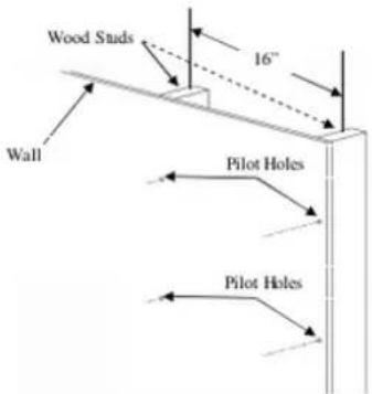
Figure 3. Wood Studs 16"Apart on Center

PLP INSTALLATION (Cont'd)
Mount the PLP
To mount the PL.P. do the following:
- Holding the PLP against the wall, select the pair of mounting holes that best suits your situation (see Figures 5, 6, and 7).
NOTE: The mounting holes are slotted to allow for a small degree of lateral movement. The mount can be centered, or shifted to the left of center, or right of center depending on stud location.
- Depending on your situation, install the lag bolts and washers into the pilot holes previously drilled, as described below.
- Option A. Install four 5/16" x 2-½" lag bolts (20) and four 5/16" washers (30) (two top and two bottom) into the mounting holes, centering the PLP on dual wood studs 16" apart on center as shown in Figure 5.
OR
- Option B. Install four 5/16" x 2- 1/2 " lag bolts (20) and four 5/16" washers (30) (two top and two bottom) into the mounting holes that are right of center on dual wood studs 16" apart as shown in Figure 6.
OR
- Option C. Install four 5/16" x 2- 1/2 " lag bolts (20) and four 5/16" washers (30) (two top and two bottom) into the mounting holes that are left of center on dual wood studs 16" apart dual

Figure 5. Mounting Holes – 16" Apart on Center (Option A)
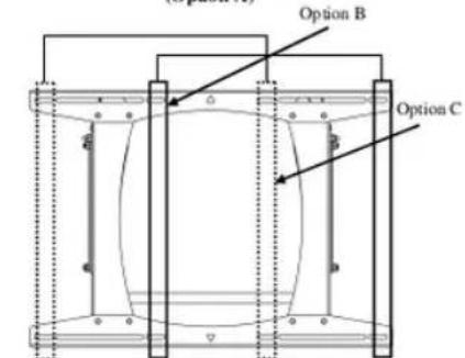
Figure 6. Mounting Holes - 16" Apart on Center (Options B and C)
ATTACH PSB TO THE DISPLAY
To attach the PSB to the display, do the following:
- To help your identify the correct PSB that matches the model number of your display, refer to the cross-reference chart at www-chiefmfg.com.
• To download the corresponding PSB installation instructions, refer to www-chiefmfg.com.
OR
- Contact Customer Service at 952-582-6480 if you have any questions about how to select the PSB that matches the model number of your display.
INSTALL THE DISPLAY
To install the display, do the following:
NOTE: Verify that all power/audio/video cables are disconnected from the display and the latching flag is lowered in the down position before attempting to mount the display.
- With the aid of another person, lift the display up to the mount on the wall, aligning mounting buttons with the teardrop slots on the mount, and lower the display firmly into place (Figure 8).
- Raise the latching flag to secure the display (see Figure 9). If the flag does not fully engage, check to ensure the mounting buttons are fully seated in the slots.
NOTE: A padlock may be installed through the hole in the latching flag for additional security.

Figure 8. Install the Display

TILT ADJUSTMENT
To tilt the display 0° to 15° down, do the following:
- Manually tilt the display 0° to 15° down into the desired position.
- If desired, tighten the nut (see Figure 10) to increase the amount of tension needed to hold the mount in the position set in Step 1.
NOTE: Tighten the nuts only to adjust the amount of tension needed to manually tilt and hold the mount in place. Do not over-tighten the nuts. Over-tightening the nuts may cause excessive wear and may damage your mount.
- Repeat Steps 1 and 2 until the desired tension is obtained.
CABLE CONNECTION
To install or remove cables, do the following:
- Manually tilt display down slightly (see Figure 10), and then pull bottom of display out (see Figure 11).
- Lower center support bar to keep the display tilted up (see Figure 12).
- Perform service. For example: Connect or disconnect the power/audio/video cables.
NOTE: The service position is not recommended as a final display position.
- Raise the center support bar and reposition the display to desired position (if necessary, refer to "TILT ADJUSTMENT" procedure) after service is completed.
WARNING: Watch for pinch points. Do not put your fingers between moveable parts.
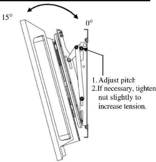
Figure 10. Tilt Display Down
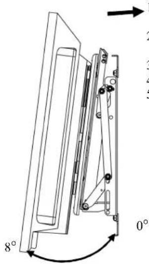
- Tilt display down (see Fig. 10)
- Pull bottom out (See Fig. 11)
- Lower support bar.
- Perform service.
- Return display to desired position.
Figure 11. Tilt Display Up (for service only)

Figure 12. Cable Connection
Marque : Chief
Modèle : PLP2000B
Catégorie : Support écran plat