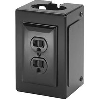
FCA540 - Support écran plat Chief - Notice d'utilisation et mode d'emploi gratuit
Retrouvez gratuitement la notice de l'appareil FCA540 Chief au format PDF.


| Type de produit | Support mural pour écran plat |
| Marque | Chief |
| Modèle | FCA540 |
| Compatibilité écran | Écrans plats de 32" à 65" |
| Capacité de charge maximale | 56,7 kg (125 lb) |
| Norme VESA compatible | 200x200, 200x400, 300x300, 400x200, 400x400, 600x400 mm |
| Inclinaison | +5° / -15° |
| Pivot | ±90° |
| Rotation (mise à niveau) | ±3° |
| Matériau | Acier à haute résistance |
| Couleur | Noir |
| Dimensions du support (L x H x P) | 89 cm x 43 cm x 5 cm |
| Poids du support | 8,6 kg |
| Fixation murale | Pour murs en béton, bois et montants métalliques |
| Contenu du kit | Support mural, vis de montage, chevilles, niveau à bulle |
| Garantie | 10 ans |
| Utilisation | Intérieur uniquement |
| Entretien | Nettoyer avec un chiffon doux et sec |
| Sécurité | Ne pas dépasser la charge maximale ; vérifier la solidité du mur avant installation |
FOIRE AUX QUESTIONS - FCA540 Chief
Questions des utilisateurs sur FCA540 Chief
0 question sur cet appareil. Repondez a celles que vous connaissez ou posez la votre.
Poser une nouvelle question sur cet appareil
Téléchargez la notice de votre Support écran plat au format PDF gratuitement ! Retrouvez votre notice FCA540 - Chief et reprennez votre appareil électronique en main. Sur cette page sont publiés tous les documents nécessaires à l'utilisation de votre appareil FCA540 de la marque Chief.
MODE D'EMPLOI FCA540 Chief
INSTALLATION INSTRUCTIONS
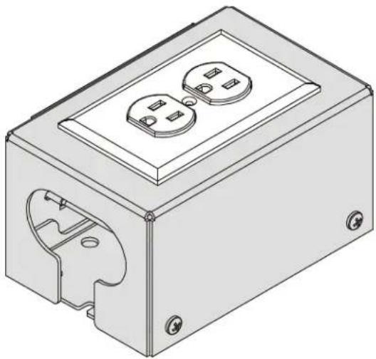
Outlet Box Accessory
DISCLAIMER
Milestone AV Technologies and its affiliated corporations and subsidiaries (collectively "Milestone"), intend to make this manual accurate and complete. However, Milestone makes no claim that the information contained herein covers all details, conditions or variations, nor does it provide for every possible contingency in connection with the installation or use of this product. The information contained in this document is subject to change without notice or obligation of any kind. Milestone makes no representation of warranty, expressed or implied, regarding the information contained herein. Milestone assumes no responsibility for accuracy, completeness or sufficiency of the information contained in this document.
Chief® is a registered trademark of Milestone AV Technologies. All rights reserved.

IMPORTANT SAFETY INSTRUCTIONS

WARNING: A WARNING alerts you to the possibility of serious injury or death if you do not follow the instructions.

CAUTION: A CAUTION alerts you to the possibility of damage or destruction of equipment if you do not follow the corresponding instructions.

WARNING: Failure to read, thoroughly understand, and follow all instructions can result in serious personal injury, damage to equipment, or voiding of factory warranty! It is the installer's responsibility to make sure all components are properly assembled and installed using the instructions provided.

WARNING: Use this mounting system only for its intended use as described in these instructions. Do not use attachments not recommended by the manufacturer.

WARNING: Never operate this mounting system if it is damaged. Return the mounting system to a service center for examination and repair.

WARNING: Do not use this product outdoors.
IMPORTANT ! : The FCA540 accessory is designed to be mounted to a Chief ceiling mount or array, and is compatible with Raco 420 single gang box or similar style outlet boxes.
--SAVE THESE INSTRUCTIONS--
DIMENSIONS



![6.25 [158.8] 3.25 [82.6] 2.03 [51.5] R0.25 [6.4] 2.13 [54.0] 3.75 [95.3]](/content/2026/06/1257464/images/9876d2178870362e2f4483e327d7fcd40f2588d70e34eeb8a0144c5869b039a7.jpg)
![3.38 [85.7] 1.40 [35.6] 1.25 [31.8] R0.75 [19.1] 4.06 [103.0] 1.00 [25.4]](/content/2026/06/1257464/images/2af420225d8bf272efa255c6588ffa610e86fe258d7d67c90dc9032063b95b47.jpg)
![5.50 [139.7] 5.00 [127.0] 2.50 [63.5] Ø 0.34 [8.6] Ø 2.50 [63.5] 3.00 [76.2] 0.20 [5.1] 0.25 [6.4] 0.34 [8.6]](/content/2026/06/1257464/images/7b419695a7cc5acad68f6ba94183f48865acdf9dc84ab062f31d132591049749.jpg)
![1.50 [38.1]](/content/2026/06/1257464/images/e2ec5c79a695f377e9aad4378c06f04bea456ec4f06240ab748e2f4974a70a5f.jpg)
COMPATIBLE WITH RACO 420 SINGLE GANG BOX OR SIMILAR STYLE OUTLET BOXES
DIMENSIONS: INCHES
[MILLIMETERS]
LEGEND
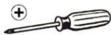
 | Tighten Fastener |  | Phillips Screwdriver |
| Apretar elemento de fijación | Destornillador Phillips | ||
| Befestigungsteil festziehen | Kreuzschlitzschraubendreher | ||
| Apertar fixador | Chave de fendas Phillips | ||
| Serrare il fissaggio | Cacciavite a stella | ||
| Bevestiging vastdraaien | Kruiskopschroevendraaier | ||
| Serrez les fixations | Tournevis à pointe cruciforme | ||
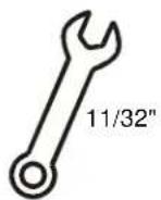
 | Loosen Fastener |  | Open-Ended Wrench |
| Aflojar elemento de fijación | Llave de boca | ||
| Befestigungsteil lösen | Gabelschlüssel | ||
| Desapertar fixador | Chave de bocas | ||
| Allentare il fissaggio | Chiave a punte aperte | ||
| Bevestiging losdraaien | Steeksleutel | ||
| Desserrez les fixations | Clé à fourche |
TOOLS REQUIRED FOR INSTALLATION
2
PARTS


D (2)
10-24 x 1/2"

E (4)
10-24 x 3/8"
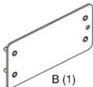
[Outlet box cover]
![Technical drawing of a mechanical bracket with mounting holes and a circular cutout, labeled C (1) [Outlet box bottom] (no other text or symbols)](/content/2026/06/1257464/images/cd3c6c362c18633d419081ee4b429f434ec3fa7daf2ceef20c02c4a759f2f3c5.jpg)

08-32 x 1/2"

G (8)
08-32

H (4)
1/4-20 × 1/2"

J (4)
1/4"

K (4)
1/4-20
INSTALLATION
NOTE: The FCA540 is compatible with the Chief ceiling mounts and arrays, and may be installed in a vertical or horizontal orientation. Proceed to Attaching to Ceiling Mount or Attaching to Arrays section.
Attaching to Ceiling Mount
- Attach outlet box bottom (C) to back of ceiling mount using two 10-24 x 1/2" Phillips tapping screws (D). (See Figure 1)
- Proceed to Completing Installation section.

Figure 1
Attaching to Arrays
- Insert four 1/4-20 weldnuts (K) into slot in mount rail. (See Figure 2)

Figure 2
- Attach outlet box bottom (C) to weld nuts (K) using four 1/4-20 x 1/2" Phillips pan head screw (H) and four 1/4" flat washers (J) into installed weldnuts (K). (See Figure 3)

Figure 3
- Proceed to Completing Installation section.
Completing Installation
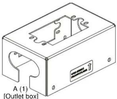
- Add outlet box cover (B) to side of outlet box (A) where outlet won't be located using four 08-32 nuts (G). (See Figure 4)

Figure 4
- Add electrical box (not included) to outlet box (A) using four 08-32 x 1/2" Phillips cap head screws (F) and four 08-32 nuts (G). (See Figure 5)
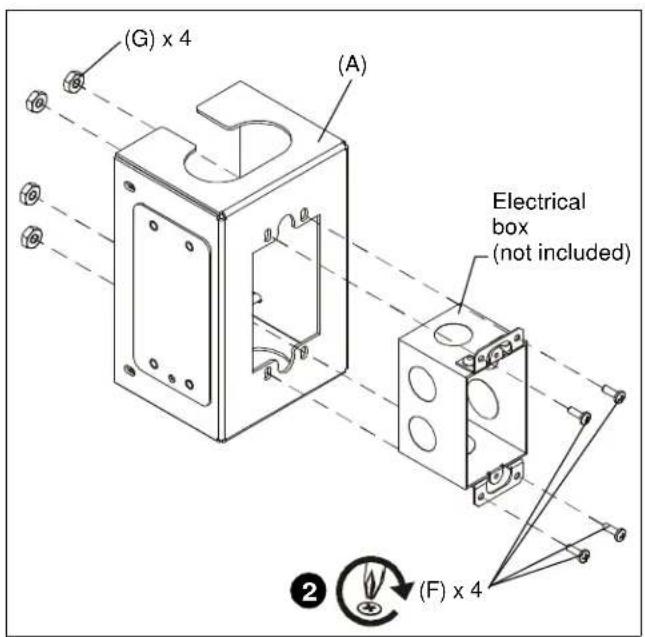
Figure 5
- Add outlet (not included) to assembly using hardware included with outlet. (See Figure 6)
- Add outlet cover (not included) using hardware included with outlet. (See Figure 6)

Figure 6
- Attach outlet box assembly to the previously installed outlet box bottom using four 10-24 x 3/8" Phillips head cap screws (E). (See Figure 7)
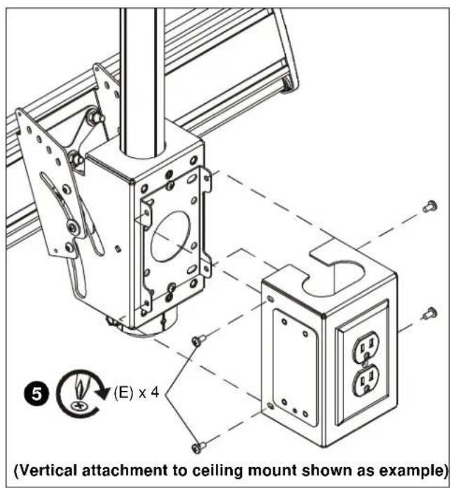
Installation Instructions
Marque : Chief
Modèle : FCA540
Catégorie : Support écran plat