
ERT 30 - Thermostat Salus - Notice d'utilisation et mode d'emploi gratuit
Retrouvez gratuitement la notice de l'appareil ERT 30 Salus au format PDF.


| Type de produit | Thermostat d'ambiance |
| Marque | Salus |
| Modèle | ERT 30 |
| Dimensions (L x H x P) | 86 x 86 x 28 mm |
| Poids | 130 g (sans piles) |
| Alimentation | 2 piles alcalines AA 1,5 V |
| Type d'écran | LCD rétroéclairé |
| Plage de température | 5 °C à 35 °C |
| Précision | ±0,5 °C |
| Programmation | 7 jours, 4 périodes par jour |
| Modes de fonctionnement | Confort, Éco, Hors gel, Manuel |
| Type de contact | Relais NO/COM, 230 V AC, 16 A max |
| Compatibilité | Chaudières gaz, électriques, pompes à chaleur |
| Indice de protection | IP30 |
| Installation | Murale, encastrée (boîte d'encastrement) |
| Entretien et nettoyage | Nettoyer avec un chiffon doux et sec. Ne pas utiliser de produits abrasifs. |
| Sécurité | Verrouillage enfant, protection antigel |
| Pièces détachées et réparabilité | Piles, support mural, bornier. Réparation par un professionnel. |
| Garantie | 2 ans |
FOIRE AUX QUESTIONS - ERT 30 Salus
Questions des utilisateurs sur ERT 30 Salus
0 question sur cet appareil. Repondez a celles que vous connaissez ou posez la votre.
Poser une nouvelle question sur cet appareil
Téléchargez la notice de votre Thermostat au format PDF gratuitement ! Retrouvez votre notice ERT 30 - Salus et reprennez votre appareil électronique en main. Sur cette page sont publiés tous les documents nécessaires à l'utilisation de votre appareil ERT 30 de la marque Salus.
MODE D'EMPLOI ERT 30 Salus
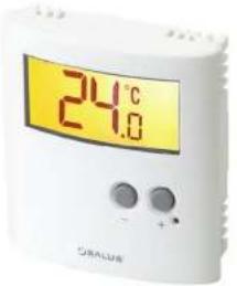
SALUS Model No: ERT30
ERT30 Digital Room Thermostat for Underfloor Heating Applications
Product Compliance
This product complies with the essential requirements of the following EC Directives:
• Electro Magnetic Compatibility Directive 2004/108/EC • Low Voltage Directive 7006/95/EC
- LOW Voltage Directive 2008/536 - EC Marking Directive 93/58/EEC
SAFETY INFORMATION
These instructions are applicable to the Salus Controls model stated on the front cover of this manual only, and must not be used with any other make or model.
These instructions are intended to apply in the United Kingdom only, and should be followed along with any other statutory obligations.
This accessory must be fitted by a Competent person, and installation must comply with the guidance provided in the current editions of BS7671 (IEE Wiring Regulations) and Part 'P' of the Building Regulations. Failure to comply with the requirements of these publications could lead to prosecution.
Always isolate the AC Mains supply before opening or removing the unit from the wall or wall box.
Please leave these instructions with the end user where they should be kept in a safe place for future reference.
INTRODUCTION
A thermostat is a device that is used to switch the heating system in your home on and off as needed. It works by sensing the air temperature and switching on the heating when the air temperature falls below the thermostat setting, and switching it off once the set temperature has been reached.
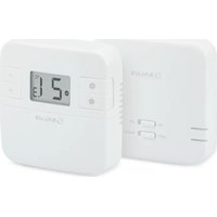
The ERT30 from Salus Controls is a stylish and accurate digital room thermostat that is fitted with a large easy to read Liquid Crystal Display (LCD). The ERT30 benefits from simple one-touch operation, and this thermostat has been specifically designed to be used with underfloor heating systems.
A back light and frost function add to the features of the ERT30.
FEATURES
• Valve Protection Function (VPF)
• Large, easy to read LCD with orange display
• Stylish casing
- user memory - Frost protection
- Reset button
Installation
Please read the important safety information at the start of this manual before you begin to install the device.
The ideal position to locate the ERT30 digital room thermostat is about 1.5m above floor level. It should be mounted in a location where the thermostat is easily accessible, reasonably lit and free from extremes of temperature.
The electrical connections to the ERT30 are made to the internal terminal strip. Connection details are shown below - no Earth connection is required for the correct and safe operation of the thermostat as the device is double insulated.
Terminal Connections
| Terminal Description Terminal Block | ||
| ← | Switched Output | |
| L Main Use | ||
| N Main: Neutral | ||
| ∅ | Temperature setback (230V AC input) | |
24V Switching
| Terminal Description Terminal Block | ||
| ← | Switched Output | |
| L1 Mamm Line | ||
| L2 Mamm Neutral | ||
| ∅ | Temperature setback (2kV AC input) | |
After installing the ERT30 in a suitable location, wiring connections can be made as shown above. The following criteria apply to the installation:
- The incoming AC mains supply should be 230V AC and fused at 2 amps. - Cavity cable size for installation is 1.5 mm², wiring colour.
- Optimum basic sector for Toubrocin is 1.5 mm/oz, adding controls should be in accordance with the current requirements of the
EE Wiring Regulations
- All wiring connections should be securely made, and be firmly
Do not restore the mains supply to the system until all associated items are fully installed.
NOTE: All electrical installation work should be carried out by a suitably qualified Electrician or other competent person. If you are not sure how to install this programmable thermostat consult either with a qualified electrician, heating engineer or your boiler/heating system supplier for advice on how to continue. Do not remove or refit the ERT30 wiring without the mains supply to the system being isolated.
Switch and Jumper Settings
Changes to the switch or jumper settings should only be made by the Engineer carrying out the installation or other qualified person.
The installer should select the switch or jumper positions required if changes need to be made to the factory default settings.
| Switch Position Function | ||
| System HEAT - Heating system (default) | COCL - Cooling system | |
| Heat Cool | ||
| Jumper Position Function | ||
| D - Setback ON- Enable (default)Function OFF - Disable | ||
| D - OutputControl Type | On Off | CK - PWM output (default)OFF - On/Off output |
| On Off | ||
| B - ValueProtection (M) | On Off | ON - Enable (default)OFF - Disable |
N.B: If the System switch is set to 'Cool', PWM mode is automatically disabled. In this case the ERT30 will only operate in On-Off mode, even if the Output Control DIP switch is set for PWM mode.
After Installation
After completing installation and powering up the ERT30 for the first time the thermostat will behave in the following way:
All the indicators on the display and the backlight will be turned up for two records. After two records, the EPT20 will then
| 22.0 |
if the Reset Button is pressed, the ERT30 will behave in the same way as described above, except that any previously saved user settings will be deleted and overwritten with the default settings.
| Function | Default Value |
| Operation Mode | Normal |
| Room Temperature | 22°C, updated within a few seconds |
| All Set Point Temperatures | 20°C |
| °C Indicator | On |
| Setback Indicator | Off |
| Heat Indicator | Off |
| Output Relay | Off |
N.B: Please be aware that after a Reset, the ERT30 output relay may turn ON if the room temperature is lower than the Set Point temperature.
USER INTERFACE AND CONTROLS
The status and operation of the ERT30 can be clearly seen on the large orange backlit Liquid Crystal Display (LCD) - this display allows the user to see at a glance the current status of the heating system.

There are few user controls for the ERT30, making the controller very easy to operate. These controls are shown below, along with a description of each of their functions.
User Control Function Summary
| Key / Operation | Symbol | Functions |
| MINUS (-) key | Decreases the selected setting | |
| PLUS (+) key | Increases the selected setting | |
| RESET button | Resets the controller to default (original factory) settings |
Operation
As previously described, the ERT30 is configured and adjusted by the use of an intuitive user interface with a minimal number of user controls, and the backlit LCD gives a highly visible, easily readable indication of the thermostat status
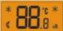
LCD Indicator Function Summary
| Indicator | Symbol | Function |
| FROST (left hand side on display) | Indicates frost protection mode is active | |
| ORISCENT | Indicates setback temperature mode is active | |
| TEMPERATURE | 88°C | Indicates either current room temperature or set point temperature |
| Right sand side on display | Indicates cooling mode is active. | |
| HEATING | Indicates heat control mode is active |
Checking the Set Temperature

Pressing either the PLUS or MINUS key once will display the current Set Point temperature:
s, the ERT30 will return to current room temperature.
After three seconds without a key press, the ERT30 will return to NORMAL mode and will display the current room temperature.
Adjusting the Set Point Temperature
Adjusting the Set Point temperature is done with the ERT30 in NORMAL mode. Press either the PLUS or MINUS key twice to enter setting mode. After doing this, the displayed Set Point temperature will flash:

Press the PLUS or MINUS key to increase or decrease the Set Point temperature within the range of 10 °C to 35 °C, in 0.5 °C steps. The Set Point temperature will stop flashing while being adjusted, but will flash again once the key is released. Pressing and holding the PLUS or MINUS key for two seconds will increase or decrease the setting quickly.
The thermostat will return to NORMAL mode after 5 seconds if no key is pressed.
Frost Protection Mode
The ERT30 has a Frost Protection mode, but this is only active when the thermostat is operating in HEATING mode. The Frost Protection mode

temperature is preset at 5 °C, this temperature is factory set and cannot be adjusted.
To enable Frost Protection press the PLUS and MINUS keys together for 3 seconds, then release them. The display will then display the Frost Protection Set Point and Frost icon;
To disable Frost Protection and return the thermostat to NORMAL mode, press the PLUS and MINUS keys together for 3 seconds.
Temperature Offset
To adjust the temperature offset press both the + and - buttons in together until SET appears in the display window you can then make your required changes with the + or - buttons in steps of 0.5°C ranging from -3.5°C to +3.5°C. Changes will then be saved. When all changes are complete the ERT30 will revert back to the current room temperature if no further buttons are pressed for 5 seconds.
OTHER FUNCTIONS AND CONTROLS
Backlight
The backlight of the ERT30 is switched on automatically whenever any of the keys are pressed. The backlight will remain illuminated for approximately 5 seconds after the last key press. If the room temperature is higher than 35 °C, the backlight will blink on and off.
The backlight will not illuminate if there is no mains supply to the controller.
Control Status
The ERT30 indicates on the LCD the control status by using a selection of display icons.
The display will show animated flame icon when in HEATING mode.

The display will show an animated snowflake icon when in COOLING mode.

Reset Button
The Reset Button is provided as a way to restore the heating controller to its default factory settings. Pressing this button will delete any previously entered settings.
Setback Temperature
The ERT30 has a provision to set a setback temperature, this is automatically fixed at 4 °C below the current set point temperature for Heating, and 4 °C above the current set point temperature for Cooling.
The Setback feature will only operate if a connection is made to the Setback terminal. The terminal is sampled every second, and if the terminal state is HIGH (above 175V AC), the Crescent indicator will be shown on the display, and the Setback temperature will be applied.
Temperatures outside the Operating Range
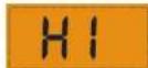
Temperatures below 10 °C are displayed without the leading '0'. Temperatures exceeding the measurable range will be indicated by 'HI' for temperatures above the upper limit, and 'LO' for temperatures below the lower limit, as shown in the images below.

Valve Protection Function
The Valve Protection (VP) function is provided as a way to avoid the control valve from sticking or seizing when not being used for long periods (e.g. during the summer).
This function is enabled by setting the Valve Protection jumper to the enable position. When enabled, the VP function will turn on the thermostat output to operate the control valve for a period of 5 minutes every week: the VP function will still operate even if the room temperature is higher than 35^ .
Pulse width modulation
Radiant panel heating systems tend to have a problem with overshooting, i.e. rooms continue to be heated even after the desired temperature has been reached and the valve has been closed. The ER730 solves this problem electronically and especially effectively using what is known as pulse width modulation, by continuously comparing set temperature with actual temperature, the lengths of opening times for the valves actuations are regulated in such a way the temperature is almost completely prevented from exceeding or falling below the set temperature. In this way, the required temperature setting is regulated in a precise and convenient way.
Note: When the ERT30 is used with radiator or convector heating systems, pulse width modulation can be switched off if necessary (see basic settings section)
ENERGY TIP
One way to set and use your room thermostat is to find the lowest temperature setting that you are comfortable with, and then leave it set at this temperature. You can do this by setting the room thermostat to a low temperature, (for example 17°C) and then increasing the setting by one degree each day until you are comfortable with the room temperature - you won't have to adjust the thermostat further, as adjustment above this setting will waste energy: a 1°C increase in temperature is equal to 3% of your heating costs.
Maintenance
The CRT30 digital room thermostat requires no special maintenance. Periodically, the outer casing can be wiped clean using a dry cloth (please DO NOT use solvents, polishes, detergents or abrasive cleaners, as these can damage the thermostat).
There are no user serviceable parts within the unit; any servicing or repairs should only be carried out by Salus Controls or their appointed agents.
Should the ERT30 room thermostat fail to function correctly, check;
- Mains supply to the ERT30 is switched on.
- Heating system is switched on.
- If the ERT30 is still not functioning correctly,
press the Reset Button.
WARRANTY
Salus Controls warrants that this product will be free from any defect in materials or workmanship, and shall perform in accordance with its specification, for a period of two years from the date of purchase. Salus Controls sole liability for breach of this warranty will be (at its option) to repair or replace the defective product.
Product Specification
Model: ERT30
Type: Non-programmable digital room thermostat designed for underfloor heating applications
Operation
Control method: 1. RIFM control
- Poid control (deault)
- On - Off control
Temperature Measurement
Temperature display range: 5.0°C - 45.0°C Temperature display resolution: 0.5°C
Temperature setting range: 10.0 °C - 35.0 °C
Temperature setting resolution
Frost protection setting: 5.0°C
Memory Backup
Type: Internal memory (EEPROM)
Switching
Switching Voltage: 230V AC / 50Hz
Switching Current: Switching current 0.2A resistive IP30 Class 2
Environment
Operating Temperature: 0°C to +40°C Storage Temperature: -20°C to +60°C
Salus Controls plc, Salus House, Dodworth Business Park South, Whinby Road, Dodworth, Barnsley S75 3SP
Sales Email: sales@salus-tech.com
Tel: +44 (0) 1226 323961 Fax: +44 (0) 1226 240588
Technical Email: tech@salus-tech.com Tel: 01226 323961
SALUS
CE

- ERT30 Digital Room Thermostat for Underfloor Heating Applications
- Product Compliance
- SAFETY INFORMATION
- Always isolate the AC Mains supply before opening or removing the unit from the wall or wall box.
- INTRODUCTION
- FEATURES
- Installation
- Switch and Jumper Settings
- After Installation
- USER INTERFACE AND CONTROLS
- Operation
- Adjusting the Set Point Temperature
- Frost Protection Mode
- Temperature Offset
- OTHER FUNCTIONS AND CONTROLS
- Backlight
- Control Status
- Reset Button
- Setback Temperature
- Temperatures outside the Operating Range
- Valve Protection Function
- Pulse width modulation
- ENERGY TIP
- Maintenance
- WARRANTY
- Product Specification
- Temperature Measurement
- Memory Backup
- Switching
- Environment
- Sales Email: sales@salus-tech.com
Marque : Salus
Modèle : ERT 30
Catégorie : Thermostat