
940 (1997) - Voiture VOLVO - Notice d'utilisation et mode d'emploi gratuit
Retrouvez gratuitement la notice de l'appareil 940 (1997) VOLVO au format PDF.


| Type de produit | Voiture |
| Marque | Volvo |
| Modèle | 940 |
| Année | 1997 |
| Carburant | Essence sans plomb (95 RON) |
| Capacité du réservoir | 75 litres |
| Boîte de vitesses | Manuelle 5 rapports ou automatique |
| Direction assistée | Oui |
| Climatisation | Manuelle ou automatique selon version |
| Toit ouvrant électrique | En option |
| Vitres électriques | Avant et arrière |
| Rétroviseurs électriques | En option |
| Airbags | Conducteur et passager (SRS), latéraux (SIPS) |
| Ceintures de sécurité | 3 points à inertie avant et arrière, prétensionneurs |
| Système audio | Autoradio cassette RDS, ampli 4x20W, possibilité changeur CD |
| Alarme antivol | En option avec télécommande |
| Freins | Disques avant et arrière, ABS en option |
| Pneus | Pression à vérifier régulièrement |
| Entretien | Vidange moteur, filtre à huile, liquide de refroidissement, plaquettes de frein |
| Capacité du coffre | Environ 530 litres (berline), variable (break) |
| Poids à vide | Environ 1450 kg (estimation) |
FOIRE AUX QUESTIONS - 940 (1997) VOLVO
Questions des utilisateurs sur 940 (1997) VOLVO
0 question sur cet appareil. Repondez a celles que vous connaissez ou posez la votre.
Poser une nouvelle question sur cet appareil
Téléchargez la notice de votre Voiture au format PDF gratuitement ! Retrouvez votre notice 940 (1997) - VOLVO et reprennez votre appareil électronique en main. Sur cette page sont publiés tous les documents nécessaires à l'utilisation de votre appareil 940 (1997) de la marque VOLVO.
MODE D'EMPLOI 940 (1997) VOLVO
Instruments, switches and controls

Instruments
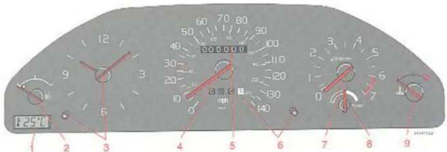
1 Outside temperature gauge (option)
Shows the temperature immediately above the road surface while driving. An orange warning light comes on when the outside temperature is between +2° and -5°C.
NOTE: When car is moving slowly or is stationary, engine heat may cause the gauge to show an artificially high temperature.
2 Fuel gauge
The fuel tank holds about 75 litres – 16 Imp. galls. Once the lamp in the instrument lights up, about 6 litres – 1.3 Imp. galls usable fuel remains in the tank.
3 Quartz clock
The clock is electric, and runs off the car battery. To set the time, push button in and turn.
1:2
4 Speedometer
5 Odometer
6 Tripmeter Resetting of trip meter
Used for measuring shorter distances (last figure represents 1/10 mile/km). Push in knob to reset meter.
If the last figure on the tripmeter is red on a white background the speedometer and the tripmeter have been replaced.
The mileage and date of replacement have been noted in your Service booklet.
7 Tachometer
Indicates engine speed in revolutions per minute. The red lined section should only be used occasionally e.g. when accelerating or overtaking. Engine should not be operated in red section.
Max permissible engine speed is 6000 rpm.
8 Boost pressure gauge
The boost pressure gauge is divided into two sections – one black and one white. With the needle in the black section the engine acts as a naturally aspirated engine – without the turbo-charger. To make driving more economical, keep the needle in this section as much as possible. With the needle in the white section the turbocharger is engaged.
9 Temperature gauge
Shows temperature of cooling system. If the pointer repeatedly approaches the red section check coolant level and fan belt tension immediately.
Indicator and warning lamps

1 Direction indicator, left
2 Direction indicator, right
3 Fault in exhaust emission
4 Direction indicator, caravan
5 Not connected
6 Low washer fluid level
If lamp glows continuously there is only about 0.5 to 1 litre fluid remaining in washer reservoir.
7 Rear fog lamp
8 Bulb failure
9 Battery charge failure
10 Low engine oil pressure
11 Headlamp main beams
12 Brake circuit failure
13 Parking brake
14 ABS (anti-lock braking system) malfunction (optional equipment)
15 Not connected
16 Not connected
17 4th speed disengaged (automatic transmission)
18 Fasten seat belts
19 SRS (optional equipment)
20 Not connected
21 Not connected
Warning lamps
When the ignition is switched on, i.e. before the engine is started, all warning lights should come on to test the bulbs. If any warning light
stays on after the engine has started, the cause must be investigated immediately.
Brake circuit failure

If the light comes on while driving or during braking, the brake fluid level is too low. Stop immediately and check the level of fluid in the brake fluid reservoir (see the back cover for location).
If the level is under MIN in any part of the reservoir: do not drive any further but have the car towed to a workshop to be checked and repaired.
Low oil pressure

If this lamp comes on when the engine is running, the oil pressure is too low. Switch off the engine immediately and check the oil level, see 7:6.
After hard driving, the lamp will come on occasionally when the engine is idling. This is normal provided it goes off when the engine speed is increased.
Bulb failure

The light will come on if any of the following bulbs are defective:
Dipped beams
Tail lights
Brake lights (if the lamp glows when the brake pedal is depressed)
Check the fuse and bulb.
Fault in exhaust emission control system

If this lamp stays on after the engine has started, a fault has been detected in the fuel/ignition systems, indicating that the engine does not fulfil emission control requirements. The vehicle should be checked by an authorised Volvo dealer.
Battery charge failure

A warning lamp will glow if the alternator is not charging the battery. If this happens while the engine is running, check the tension of the alternator drive belt without delay.
Parking brake

Warning lamps
Anti-lock Braking System (ABS)

ABS prevents wheel locking during severe braking conditions. If the warning lamp lights up there is a malfunction of the ABS system (the standard braking system will however function) and the vehicle should be driven to a Volvo dealer for an inspection.
See 3:13 for more information about ABS.
Airbag (SRS)

(certain models)
If the lights comes on (or stays on once the vehicle has been started) the SRS diagnostic system has detected a fault. Drive immediately to a Volvo dealer for an inspection of the system. See chapter 2 for more details.
Direction indicators, main/dipped beams and headlamp flasher

Direction indicators, main/dipped beams and headlamp flasher
1 Lane changing, overtaking Light pressure upwards or downwards. The lever will return to the neutral position when released.
2 Normal turns
3 Headlamp flasher (headlamps off) Pull the lever towards the steering wheel. The main beams remain on until the lever is released.
3 Main beam/dipped beam switching (headlamps on) Pull the lever towards the steering wheel, past the headlamp flash position, and release it.
A blown direction indicator bulb will cause the indicator light to flash more rapidly than usual.
Hazard warning lamps
All exterior direction indicators flash when the switch is actuated. Use this to inform other road users of an obstruction or hazard caused by your vehicle. Regulations governing the use of the hazard warning lamps vary from country to country.
Windscreen wash/wipe, Headlamps, Ignition switch/steering wheel lock


Windscreen wash/wipe, headlamp wash/wipe
1 Intermittent wiping
Useful when driving in misty weather conditions or light rain. The wipers will make a single sweep every six seconds.
2 Single sweep
Slightly depress the lever. The wipers return to the park position when the lever is released. Especially useful in light rain.
3 Normal speed
4 High speed
5 Windscreen wash/wipe and headlamp wash/wipe
The washers are operated in this position and the windscreen wipers make 2 or 3 sweeps after the lever is released. The headlamp washers operate at the same time as the windscreen washers.
0 Lock position
The steering wheel is locked when the ignition key is withdrawn from the lock. If the ignition key is difficult to turn, this is due to tension in the steering column lock. Turn the steering slightly left and right to loosen. In order to reduce car theft, make sure the steering wheel lock is engaged before leaving the car.
I Intermediate position "Radio"
Certain electrical components can now be operated. The ignition system is switched off.
II Drive
Key position during driving. Tail lights, numberplate lights and instrument illumination are all on.
III Start position
The starter motor is engaged. Release the key as soon as the engine starts. It automatically springs back to the engine-running position.
WARNING! The ignition key should never be removed from the lock while driving or while the car is being tow

Headlamps and parking lights
0 All lights off
Ignition at "0" all lights off.
Ignition at I, II or III Dimdip, parking lights, numberplate lights and instrument illumination switched on.
Dipped headlights (markets outside UK) are automatically switched on when the ignition key is in position II and cannot be turned off.
Parking lights and Dim dip on.
Do not use the parking lights when driving.

Headlamps and parking lights
Ignition at "0" all lights off.
Ignition at I, II or III headlamps, parking lights, numberplate lights and instrument illumination switched on.
Note! You have to turn the headlight control to 📋 in order to switch on the main beam.
Electric sun roof, Heated rear window

Sun roof
The sun roof can be operated either as a sliding roof or to provide different ventilation positions (by raising or lowering the rear section.) The ignition key must be turned to position II before the sun roof can be operated. Press switch at appropriate point to open or close the sun roof. Read more about the sun roof on page 1:20. In the event of malfunction, see pages 1:20 and 5:3.
Heated rear window
Heated door mirrors (certain models) Use the heated rear window and heated door mirrors for demisting and defrosting. Heating switches off automatically after 6 minutes for mirrors and 12 minutes for rear window, or when ignition is turned off. The two small orange lights go out when the heating stops. To turn off the heating when the lights are on press the switch. Press the switch again to restart the cycle.
Instrument illumination regulator
Move the regulator up - increase illumination. Move the regulator down - decrease illumination.
Front and rear foglamps, Tailgate wash/wipe, estate
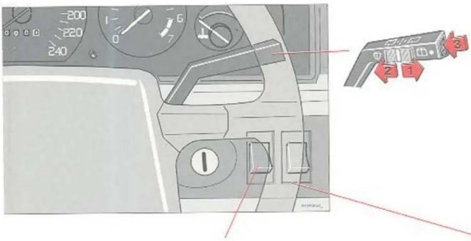
Front foglight
The front foglight is switched on and off using the switch. When the LED on the switch is on, the front foglight operates in combination with the parking light and the main/dipped beam.
Tailgate wash/wipe, estate
The tailgate window wiper/washer is operated by a switch at the end of the wiper lever.
1 The wiper operates continuously.
2 Intermittent position: the wiper sweeps approximately every 10 seconds.
3 Tailgate washer: The wiper starts operating when the washer button is depressed and continues for 2–3 strokes after the button is released.
Rear foglight
The rear foglight is switched on using the switch (this function is automatically disconnected when the engine is switched off). When the indicator lamp on the combined instrument panel is on, the rear foglight operates in combination with the main/dipped beam.
Note: Foglamp regulations vary from country to country.
Heated front seats

natural_image
Interior view of a car seat with passenger seatbelt and passenger seat tray, showing red arrows indicating airflow or movement (no text or symbols)Heated front seats
The seat heating function can be switched on and off with the switches.
On certain models, the heating is completely automatic. When the correct temperature is reached, the heating cuts out automatically.
Switch off the passenger seat heating if no-one is sitting there.
Parking brake, Cigar lighter, Ashtrays
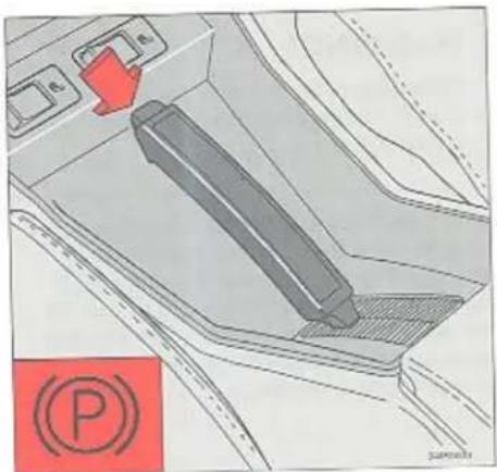
Parking brake lever
Parking brake
The parking brake (lever between the front seats) operates on the rear wheels. A dashboard warning lamp comes on when the brake is applied. Press button to release the brake, lift lever slightly and ease down.
Note: The parking brake must always be used when the vehicle is parked.
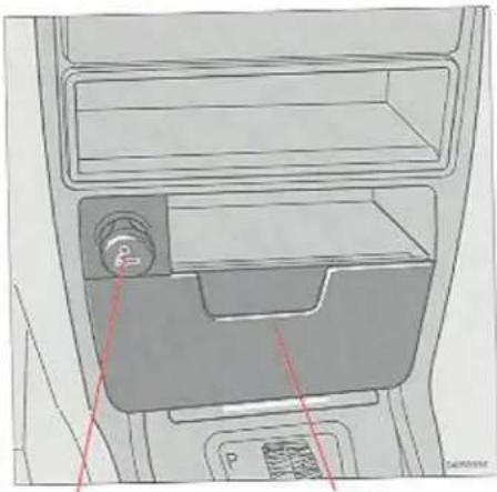
natural_image
Interior view of a vehicle air conditioner unit with labeled ports and airflow indicators (no text or symbols)Cigar lighter
Ashtray
Cigar lighter and ashtrays
6–8 seconds after being pushed in, the lighter will spring back ready for use. Empty ashtrays by pulling out to the limit and pressing down the tongue.
Electrically operated window winders Right front Right rear
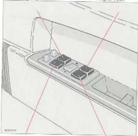
natural_image
Technical line drawing of a mechanical component with no visible text or symbolsLeft front
Left rear
The window winder switches, located in the armrests of the doors, will only function when the ignition is turned on (at position "II"). To lower press rear part; to raise press front part. The electrically operated window on the driver's side has an extra "AUTO" function. Press the switch quickly and the window opens fully. The opening can be interrupted by pressing the switch quickly once again. Note! "AUTO" is only located on the driver's side.

natural_image
Technical line drawing of a mechanical component with no visible text or symbolsCut-out switch for rear windows
In vehicles with electrically operated rear windows, use the cut-out switch in the middle to disconnect the rear window winding function.
Note: Always remove the ignition key if children are left unattended in the car.
The rear door windows can be raised or lowered with the door switch as well as the switch on the driver's door.
○ Only the driver can operate the rear windows.
WARNING!

With children in the car, check that nobody can get trapped when you are raising a window.
Note! The electrically operated window winders have an overload protector which engages if an object blocks the windows. If this happens, remove the object and wait 20 seconds. The overload protector should then have cooled down and the window winders should function normally.
Heating and ventilation – climate units
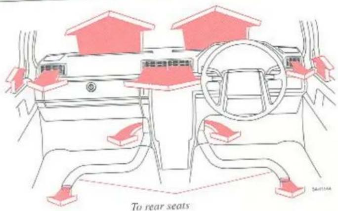
Heating and ventilation – climate units
Various types of ventilation units are available as options:
- Standard, without air conditioning (see 1:14)
-Air conditioning unit (sec 1:16)
– Fully automatic air conditioning unit (see 1:18)
Air conditioning cools the passenger compartment even if ambient temperatures are high.
Note: Sun roof and all windows need to be closed when the air conditioning unit is in use. Make sure you do not block the drainage channels on the parcel shelf and in the wheel well in the luggage compartment on the 5-door model.
Protecting the environment
The air-conditioning system now uses the new coolant R134a. This is chlorine-free and does not affect the ozone layer. In addition, R134a only contributes slightly to the so-called greenhouse effect.
When topping up or changing coolant, use R134a only. This should be done by an approved Volvo workshop.

Heating and ventilation
A Open
B Closed
C Lateral adjustment
D Vertical adjustment
Heating and ventilation system without air conditioning
Mode selector
Heating and ventilation
To obtain the maximum heat:
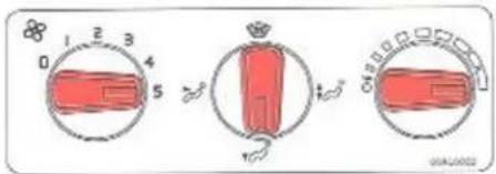
Bear in mind that a certain amount of air always enters through the air vents in the instrument panel if the vents are open, irrespective of the position of the mode selector. If you wish to obtain maximum air flow to the floor or windows, shut the air vents. If the side windows mist up, open the two air vents at the sides.
This is the coolest setting:

The air vents are open.
Setting for removing mist from the windows:

Shut the two middle air vents! If it has snowed, brush away the snow from the heating system's air inlet, i.e. the grille in front of the windscreen!
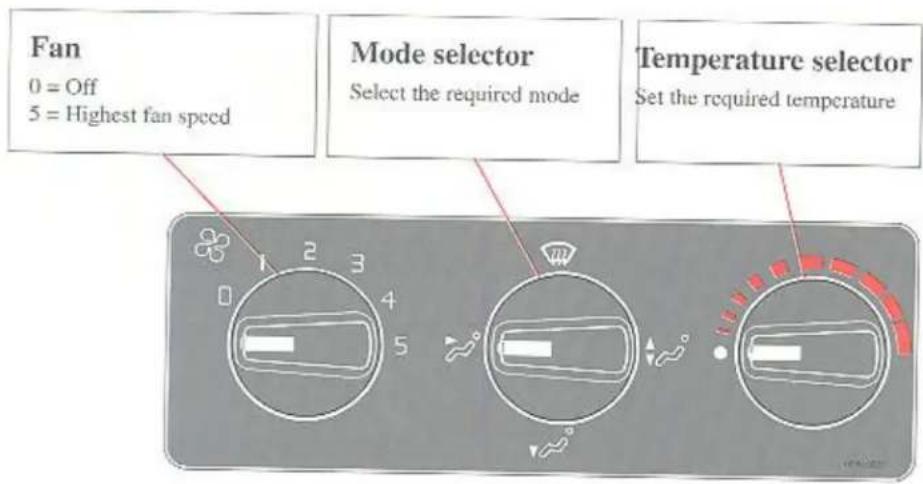
Heating and ventilation system with manual air conditioning
Fan
0 = Off
5 = Highest fan speed
Mode selector
Select the required mode
Temperature selector
Set the required temperature


When the button is depressed, air inside the car is recirculated with hardly any fresh air being taken in from outside. The lamp shows orange when Re-circulation is selected and the headlights are on. Recirculation and Defrosting cannot be selected at the same time. When the mode selector is set at defrost, recirculation is always disengaged regardless of the position of the button.

The air conditioning system is activated when the button is depressed. The lamp shows blue when the air conditioning is activated and the headlights are on. The air conditioning system is always engaged when the mode selector is set at defrost, regardless of the position of the button.
Mode selector

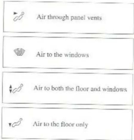
Air through the air vents

Air to the windows. The air does not recirculate in this position. The air conditioning system is always engaged.

Air to both the floor and windows

Air to the floor only

Air to the floor and air vents
Heating and ventilation
To obtain the maximum heat:

Shut the centre ventilation nozzles. When the cabin has become sufficiently warm, move the fan control to speed 2 and regulate the temperature.
This is the coolest setting:

Open the air vents.
Should be depressed. Regulate the temperature with the temperature control.
Setting for removing mist from the windows:

Move the mode selector to position √ In this position the air conditioning is always engaged!
If it has snowed, brush away the snow from the heating system's air inlet, i.e. the grille in front of the windscreen.
A few supplementary hints:
- In order to permit activation of the air conditioning system, the fan control has to be moved to at least speed 1.
- The air conditioning does not work when it is colder than +6°C.
- Use this setting to obtain rapid heating/cooling, or if you wish to exclude unpleasant exhaust fumes from the cars around you for a few minutes. This setting admits only a very small amount of air from outside. However, do not drive with this function activated for more than 10 or 15 minutes, otherwise you will risk an accumulation of stale air and mist inside the car. Regulate the temperature with the temperature control.
Bear in mind that a certain amount of air always enters through the air vents in the instrument panel if the vents are open, irrespective of the position of the mode selector.
If you wish to obtain maximum air flow to the floor or windows, shut the air vents. If the windows mist up, open the two air vents at the sides.
If there is water vapour inside the car, you can get rid of it quickly by using the air-conditioning system, even when it is relatively cold outside. Air is dehumidified before it enters the car.
Make a point of using your air conditioning system regularly to ensure that it functions properly.
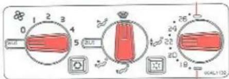
Heating and ventilation with automatic air conditioning
Fan
0 = Off
5 = Max speed
aut = Fan speed automatically regulated
Mode selector
Select mode as required aut = normal
Temperature
Set temperature desired. The dial is graduated in Centigrade or Fahrenheit.
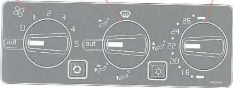


When the button is depressed, air inside the car is "recirculated" with no air being taken in from outside. The frame around the symbol lights up when this function is engaged. When the mode selector is set at defrost, recirculation is always disengaged regardless of the position of the button.
The air conditioning is engaged when the button is depressed. The frame around the symbol lights up when the air conditioning is engaged, and the symbol flashes if there is a fault in the climate unit.
The air conditioning system is always engaged when the mode selector is set at defrost, regardless of the position of the button.
Mode selector
aut
= air distribution automatically regulated

Air through panel vents

Air to the windows. The air does not recirculate in this position. The air conditioning system is always engaged.

Air through floor, windscreen and side windows.

Air through floor vents.

Bi-level. Air through floor and panel vents. Air supplied from ts is slightly colder than air at foot level.
Heating and ventilation
Automatic setting:
Maximum heating
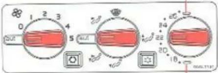
Maximum cooling
Set the mode selector at aut and select the desired temperature.
If you set the temperature at maximum cooling or heating the fan operates at the fastest speed.
Optimum demist:
Set the mode selector in position

In this mode, the air conditioning system is always engaged irrespective of position of this button. Recirculation is disengaged at the same time.
A few supplementary hints:
- Use this setting for a few minutes if you wish to exclude unpleasant exhaust fumes from the cars around you, since this setting admits only a very small amount of air from outside. However, do not drive with this function activated for more than 10 or 15 minutes, otherwise you will risk an accumulation of stale air and mist inside the car.
- The air conditioning system does not work when it is colder than +6°C.
Make a point of using your air conditioning system regularly to ensure that it functions properly.
Note: Do not place anything over the solar sensor which is located in the speaker grille on the right side, or else the climate unit will receive faulty climate information.
If there is any leakage of water under the car, this may be caused by the climate unit which emits moisture in the form of condensed water in hot weather.
Indication of fault in the climate unit
The button has a lamp which indicates that there is a fault in the unit. If the lamp begins to blink when the ignition is turned on then there is a simple fault in the unit. If the lamp continues to blink for more than 20 seconds there is a more serious fault. Contact your Volvo workshop.
Bear in mind that a certain amount of air always enters through the air vents in the instrument panel if the vents are open, irrespective of the position of the mode selector.
If you wish to obtain maximum air flow to the floor or windows, shut the air vents. If the windows mist up, open the two air vents at the sides.
If there is water vapour inside the car, you can get rid of it quickly by using the air-conditioning system, even when it is relatively cold outside. Air is dehumidified before it enters the car.
Difficult weather conditions
When driving in very humid conditions, heavy rain, sleet, etc., it may be better to use the manual rather than the automatic setting to defrost the windows. Set the mode selector to "Defrost" or "Defrost/floor" and the fan speed to 3 or higher. Also shut the central air vents.
Sun roof
natural_image
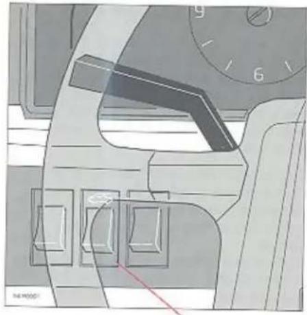
Interior view of a car dashboard with steering wheel, dashboard, and steering wheel (no visible text or symbols)Electrically operated sun roof
The sun roof functions in two ways: firstly as a conventional sun roof and secondly as a ventilation hatch whereby the rear edge can be raised to admit fresh air.
The ignition key must be in the "drive" position to permit operation of the sun roof. To slide open the sun roof: press on the lower edge of the switch.
To shut the sun roof: press on the upper edge of the switch.
To open the rear of the sun roof (ventilation position): press on the upper edge of the switch. Press on the lower edge to lower the hatch to the shut position.

natural_image
Diagram of a car interior showing a smartphone mounted on the roof with a red arrow pointing to it (no text or symbols present)Ventilation position

natural_image
Diagram of a vehicle roof with a red arrow indicating direction (no text or symbols)Sun roof
Overload protector
Note: The electrically operated sun roof has an overload protector which engages if an object blocks the hatch.
If this happens, remove the object and wait 20 seconds. The overload protector should then have cooled down and the sun roof should function normally.
WARNING!
Care should be taken when operating the electric windows or sunroof of a car as fingers or hands can become trapped. This is particularly important with young children in the car.

natural_image
Interior view of a vehicle showing the window with a red arrow pointing to the door (no text or symbols present)Sun visor
Sun visor
The sun roof also features a manually operated sliding sun visor on the inside of the hatch.
The sun visor automatically slides back somewhat when the ventilation position is selected.
Note: Do not shut the sun visor when the sun roof is in the ventilation position, otherwise you risk damaging the mechanism.
Body and interior
Doors and locks 2:2
Alarm 2:6
Front seats 2:8
Rear view mirrors 2:10
Courtesy lighting 2:11
Storage compartments 2:12
Bonnet 2:13
Cargo space 4-door models 2:14
Cargo space, estate 2:16
Seat belts 2:20
Child safety 2:22
Airbag (SRS) 2:26
Cargo space - loading 2:32
Child restraint anchorages (Australia) 2:35
Keys

natural_image
Top-down diagram of a car with red sensors and a key, no text or symbols presentOwner's key
This key operates all locks in the vehicle

natural_image
Top-down line drawing of a car with a key and handle, no text or symbols presentService key
Front doors
Starting (ignition)/steering wheel lock
Electronic start inhibitor (Immobilizer)
Each of the car's keys contains a coded transmitter and receiver (transponder). The code in each key is transmitted via an aerial in the ignition lock and compared to the corresponding code entered in the start inhibitor control module. The car can only be started if the right key with the correct code is used. If you loose one of your car keys, you should take all the remaining keys to an authorised Volvo workshop, as all the keys have to be recoded.
Number tag
The numbers of the keys (master keys and secondary keys) are stamped on a separate number tag. Keep the number tag separate from your bunch of keys so that nobody else can copy down the number. Keep it in a safe place.
Locking and unlocking doors with central locking
All doors and the boot are locked and unlocked automatically from the lock on the driver's door.
Turn the key 1/4 turn clockwise to unlock all doors and the boot. Turn it 1/4 turn anticlockwise to lock all doors and the boot. The front passenger door can also be locked and unlocked using the key. This does not affect the locking of the other doors or the boot. You can lock all doors from the inside by pressing down the lock knob on the driver's side. Doors can be opened from the inside even if the lock knobs are down.
The key must be used to lock the driver's door from the outside.
WARNING!

Keep doors unlocked – lock knobs up – when the car is being driven! In an accident the emergency services will be able to get into the car. Remember that the child safety lock on the rear doors can only be opened from the outside if the lock knob is up. The rear door lock knobs can be pushed up from the inside with the inner door handle. The rear doors may then be opened from the outside.
Keys

Large key operates boot lock
Boot lock
Vehicles with central locking: you can either lock or unlock the boot by means of the driver's door lock. You can also operate the boot lock directly with the owner's key even if the vehicle is centrally locked.

Unlocking

Locking
Withdraw key in vertical position. The boot lock can also be disconnected from the central locking system by turning the key anti-clockwise as shown below:
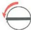
Withdraw key in horizontal position.
The boot is now always locked. This option can be used for instance if you lend your car to somebody. If you hand over the service key to the driver it will not be possible to open the boot.
To reconnect the lock to the central locking system:
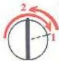
Withdraw key in vertical position.
Move to right to engage
Child safety lock
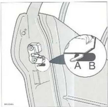
The child safety lock can only be adjusted with the rear door open.
A The door lock functions normally
B The door cannot be opened from the inside. Normal operation from outside.
Remember, in the event of an accident, the rear seat passengers cannot open the doors from the inside with the lever in position B. See warning on 2:2.
Remote-controlled central locking without alarm (certain markets)
natural_image
Illustration of a hand holding a handheld device with a car in the background (no text or symbols)
natural_image
Illustration of a car key with two compartments and a handle, no text or symbols presentRemote control
Remote-controlled central locking (extra equipment)
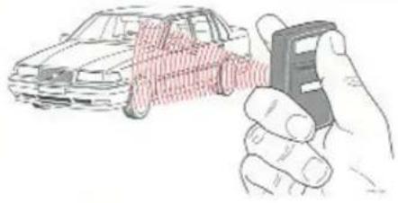
Your car can be fitted with a remote-controlled central locking system as an optional extra. The system makes it possible to operate the door and boot locks without a key. Two coded remote controls are supplied with the car. The remote control can be used to lock/unlock all doors and the boot at a distance of 3-5 metres from the car.
Unlocking
Press the large button on the remote control. You will hear a short beep. Wait for two short light signals from the car's indicators. The courtesy light comes on at the same time. All the doors and lids are now unlocked.
Locked position (Locking)
Close all doors and lids. Press the large button on the remote control. You will hear a short beep. Wait for a long light signal from the car's indicators. All doors, lids and the bonnet are now locked.
Volvo recommends that the remote control should not be used to lock the doors from the inside. For safety reasons, it is not possible to lock the doors when the ignition key is in position I or II. However, it is possible to unlock them. To prevent theft, the remote control should be left on the key ring. If you have to lend your car to someone you do not fully trust, lend your service key to this person without the remote control. Contact your Volvo dealer immediately if you lose either of the remote controls. More information about the keys to the car can be found on page 2:2.
Points to remember
If you unlock your car with the remote control, but do not actually open any of the doors or the boot within two minutes, the doors and the boot are locked automatically.
Locking and unlocking with the key
If you only use the car's key, the indicators will not produce an acknowledge signal.
The small button
Only to be used in combination with the alarm.
Remote-controlled central locking without alarm (certain markets)
Cars with electronic start inhibitor
On certain markets, cars with an electronic start inhibitor are fitted with an LED on the dashboard. A flashing LED indicates that the electronic start inhibitor has been activated.
Programming new remote controls
All remote controls must be programmed at the same time (a maximum of 4 remote controls).
Programming your new remote controls:
- Close all the doors, the bonnet and the boot.
- Switch the ignition on and off 5 times within ten seconds and leave the ignition on the fifth time.
- Press one of the two buttons on each remote controls.
- Note! The first remote control has to be programmed within 15 seconds. The rest must be programmed a maximum ten seconds apart from each other.
- Switch off the ignition and test the remote controls.
- If you are unsure how to programme your remote controls, please contact your Volvo dealer.
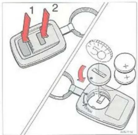
NOTE! The battery terminal is sensitive!
WARNING!

Do not lock the doors with the remote control from inside the car. In the event of an accident, locked doors would prevent emergency services from gaining access to the car quickly. Volvo recommends that doors should not be locked from the inside with the remote control.
If your remote control beeps three times every time you press one of the buttons, replace the batteries either at the next service or within a few weeks. As a preventative measure, Volvo recommends that you replace the battery at least once a year.
- Remove the cover on the back of the remote control using a coin.
- Replace the batteries (3 volt batteries, type CR1220).
- Replace the cover and check it fits tightly so that water cannot get in.
- Let your Volvo dealer help you to dispose of your batteries in an environmentally-friendly way.
- Avoid touching the batteries and their contact surfaces with your fingers.
Remote-controlled central locking with alarm (certain markets)
Activating your alarm
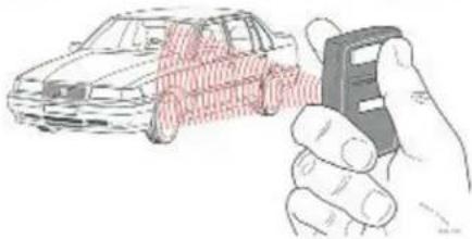
Close all doors and the boot. Press button 1 on the remote control. You will hear a short beep. Wait for a long light signal from the car's indicators. All doors, lids and the bonnet are now locked, and the alarm is activated. The LED on the dashboard blinks when the alarm is activated.
Deactivating your alarm
Press button 1 on the remote control. Wait for two short light signals from the car's indicators. The courtesy light will come on, and all the doors and lids will be unlocked.
NOTE!
If, for some reason, your remote control does not work, if you have lost it or if it has been damaged and you still want to start the car, proceed as follows: Open the driver's door with the key. The alarm is triggered and the horn sounds. Wait until the horn has sounded for about 30 seconds. Start the car within 5 seconds of the horn stopping. The alarm system is now disconnected. The alarm can then only be reconnected with a working remote control.
If any of the sensors has been triggered or an attempt has been made to break into the car without a key, the above starting method cannot be used. If this is the case, the car can only be started if you have a working remote control.
natural_image
Illustration of a hand holding a car with a sensor or sensor device, next to a car (no text or symbols visible)Remote control
Points to remember
- The alarm is deactivated when the ignition is switched on.
- If the LED glows for 5 seconds, this indicates a fault in one of the alarm loops (e.g. a door that has not been properly closed).
- If you deactivate the alarm but do not actually open any of the doors or lids within two minutes, the alarm will be reactivated (and the doors relocked). If you are still in the car and the alarm is activated for some reason, the alarm will be triggered when you try to start the car. If this happens, you must deactivate the entire alarm system using your remote control. See next page!
- If the alarm is triggered, the additional horn in the engine compartment will sound for
30 seconds. The car's indicators also flash for five minutes.
5. If the LED glows when the alarm has been deactivated, this indicates that an attempt has been made to break into the car.
6. If for any reason you want to attract immediate attention while you are inside or outside the car and the alarm is deactivated and the ignition switched off, you should set off the panic alarm in the following way: press the small button (2) on the remote control for 3 seconds. The signal horn will sound and the indicators flash for 30 seconds. You can stop the panic alarm by pressing either of the buttons on the remote control.
7. You can lock the car even if one of the doors is open. It is therefore important to make sure that your key is not in the car before the last door is shut.
Remote-controlled central locking with alarm (certain markets)
Disconnecting the entire alarm system
You can use this function when the car is being serviced or if you are lending your car to someone. You should not hand over your remote control to any unauthorised person. This avoids unnecessary programming of other remote controls not in your possession. Disconnecting the alarm: Deactivate the alarm and switch on the ignition. Press button 1 for 3 seconds. Wait for two short light signals from the car's indicators. The dashboard's LED will confirm this with a short flash every three seconds.
The alarm is reconnected when you activate it. When replacing the car's battery (alarm with additional siren)
Deactivate the alarm. Switch the ignition on and off. Disconnect one of the battery terminals in the engine compartment within 15 seconds. The alarm's siren is reconnected when the battery voltage is reconnected.
Programming new remote controls
All remote controls must be programmed at the same time (a maximum of 4 remote controls). Programming your new remote controls:
- Close all the doors, the bonnet and the boot.
- Switch the ignition on and off 5 times within ten seconds and leave the ignition on the fifth time.
- Press one of the two buttons on each remote control.
- Note! The first remote control has to be programmed within 15 seconds. The rest must be programmed a maximum ten seconds apart from each other. When the alarm system has accepted the code from each remote control, the LED on the dashboard glows briefly and then flashes rapidly.
- Switch off the ignition and test the remote controls.
- If you are unsure how to programme your remote controls, please contact your Volvo dealer.
Disconnecting the sensors
Your car may also be fitted with additional sensors which increase the security of your car.
Tilt sensor: reacts if the car is tilted and will be activated if someone tries to steal your wheel, etc.. It is advisable to disconnect the tilt sensor during ferry journeys, etc..
Ultrasound sensor: reacts to movements inside the passenger compartment. Remember not to leave children or dogs in the car.
Glass breakage sensor: reacts to the sound of breaking glass.
Disconnecting the sensors: deactivate the alarm and switch on the ignition. Press the button 1 on the remote control for a short while. Wait for a short light signal from the car's indicators, then reactivate the alarm.
The sensors will be reconnected the next time you switch on the ignition or activate the alarm.
Note! When you disconnect one sensor, all the sensors are disconnected
Front seats

Height adjustment
The front part of the seats can be adjusted to three different levels and the rear part to four, using the control lever on the side of the seat.
Lever forward = front height adjustment Lever backward = rear height adjustment
Height adjustment passenger's seat
The passenger's seat is fixed to the floor. The front and rear sections of the seat can be adjusted to two different heights. Hand tools must be used when carrying out these adjustments.
Forward-backward adjustment
Pull up the bar to slide the seat backwards or forwards. Make sure that the seat latch has engaged after adjusting the seat.
WARNING!

Do not adjust the seat while driving.
Electrically operated front seats
Electrically controlled driver and passenger seats without memory function
If your Volvo is equipped with electrically operated front seats, you can use the two switches beside the seats to adjust the following: Height of the seat's front edge
Electrically operated seats with memory function Programming:
Three settings can be stored. After adjustment of the seat, press button MEM while at the same time pressing memory button 1. Memory buttons 2 and 3 can be used to store a further two seat adjustment settings.
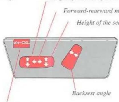
Stop button
(only for seats without memory) The STOP button is an emergency stop control. It disconnects all the other switches so that the seat setting cannot be altered by mistake.
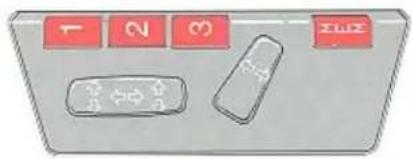
Setting:
Hold down one of the memory buttons (1, 2 or 3) until the seat stops.
If one of the setting buttons is released the seat will stop moving immediately for safety reasons.
Emergency stop (seat with memory function)
If the seat starts moving unintentionally, press one of the buttons and it will stop.
Ignition key
The ignition key does not need to be in the ignition switch to adjust the seats.
NB! Electrically operated seats have an overload protector which is activated if a seat is blocked by an obstacle. If this happens, switch off the ignition (ignition key turned to position 0) and wait for approximately 20 seconds before you use the seat adjustment facility again.
WARNING!

When adjusting the seats, ensure that there are no objects in front of or behind the seats. Make sure that none of the rear seat passengers can get trapped when you adjust the seat. To avoid the risk of children getting trapped ensure that they do not play with switches.
Rear view mirrors

B = Anti dazzle position
natural_image
Diagram showing a car side mirror with red directional arrows indicating movement or force (no text or symbols present)Adjustment of mirror

Switches, door mirrors
Rear view mirror
A Normal position
B Night position, reduces glare from following headlights
Some models are fitted with wide angle door mirrors to eliminate blind spots.
Remember that these mirrors distort angles and distances,
Manually adjustable door mirrors
Adjust mirror with control lever to desired position.
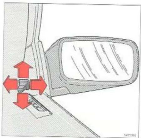
Electrically adjustable door mirrors (optional)
The control switches are located in the driver's door arm rest.
A Adjustment sideways
B Adjustment up/down
Never use ice scrapers made of metal as they can easily scratch the mirror surface.
WARNING!
The mirrors should always be adjusted before driving.

Courtesy lighting, Reading lights, Door switches

Courtesy light

natural_image
Illustration of a hand using a red tool to adjust a seatbelt between two doors (no text or symbols present)Press and turn to switch light off
Courtesy lighting, Reading lights
The courtesy lighting comprises a roof light and reading lights for the front seats.
1 Light always on
2 Light always off
3 Light is on when either the front or rear door is opened.
Cars with automatic air conditioning
The courtesy light has a built-in timer which switches off the light after approximately 7 seconds, thus giving you time to find the ignition switch at night.
Door switches
The interior light and the warning lights in the rear end of the doors come on when a door is opened.
To avoid battery drain when the doors are opened for prolonged periods, these lights can be switched off by pushing in and turning the door light switches slightly clockwise.
When the door is closed the switch will return to its normal position.
Storage compartments
natural_image
Illustration of a fabric or net with visible folds and texture, no text or symbols presentCAUTION!

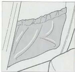
Do not place heavy objects on the rear window shelf as these can be thrown about when braking suddenly. Always secure large and heavy objects with the seat belts.

natural_image
Line drawing of a printer holder with ventilation slots and base tray (no text or symbols)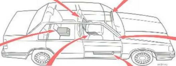
natural_image
Side view line drawing of a car with red arrows indicating airflow or movement, no text or symbols present
natural_image
Line drawing of a car interior showing the seat and dashboard (no text or symbols)
natural_image
Pure technical line drawing of a mechanical component without any text, numbers, or symbols
natural_image
Technical line drawing of a mechanical component with two views (top and side), no text or symbols present.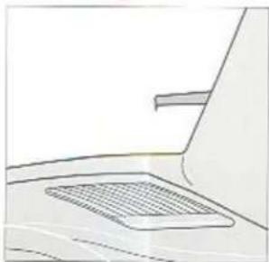
natural_image
Simple line drawing of a laptop with a mesh screen on the front panel (no text or symbols)To open the bonnet
natural_image
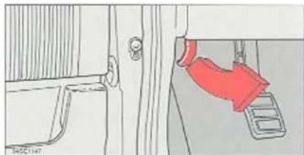
Diagram showing a door mechanism with a red hand pressing down on a pedal (no text or symbols present)Pull release handle...
natural_image
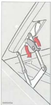
Technical diagram of a mechanical assembly with red directional arrows indicating motion (no text or symbols)
natural_image
Technical line drawing of a mechanical assembly with a compass tool (no text or symbols)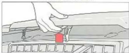
natural_image
Illustration of a hand pressing down on a vehicle's side panel with a red component (no text or symbols visible)...lift catch and open
Turn catch to open fully
To open the bonnet
Pull the release handle beneath the right hand end of the dashboard. The bonnet will spring out of its lock.
Lift the bonnet slightly and depress the safety catch. Open the bonnet.
Check that the bonnet locks properly when closing.
The normal opening position for the bonnet is approximately 55^ . By turning the catches on the hinges as illustrated, the bonnet can be opened to the vertical position. The catches return to their normal position on closing the bonnet.
Take care in low roof garages!
Boot 4-door models
Tool kit
Warning triangle
(certain markets, not UK)

natural_image
Technical line drawing of a car interior showing structural components and wiring (no text or symbols)Jack
Crank handle
The jack has to be completely folded in order
to fit in its holder.
Use the strap to fasten the jack securely in
place.
Switch positions
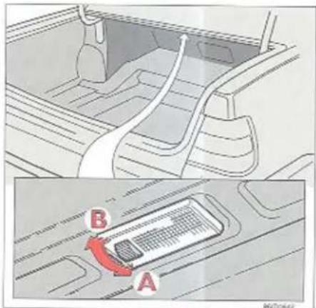
Boot light
A The light is always off.
B The light comes on when the boot is opened.
Boot hatch
natural_image
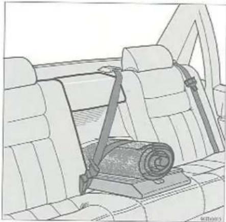
Line drawing of a car seatbelt with a roller being inserted, no text or symbols presentUse seat belt to secure luggage
WARNING!

If use is made of the boot hatch to carry luggage it is essential that the load is secured safely to prevent injury to occupants in the event of sudden braking.
Sharp edges on the load should be covered for protection.
Boot hatch
The panel behind the rear seat armrest can be removed if long objects such as skis are to be transported.
Protective bags should be used to avoid soiling the upholstery.
Please note that only light loads, such as skis, should be carried in this manner.
Max. length = 2 m (6.4 ft)
Max. weight = 15 kg (33 lbs)
WARNING!

Take care when loading/unloading the vehicle. Always turn off the engine and apply the parking brake. This will prevent the vehicle from moving if the gear lever is accidentally moved out of neutral.
Tailgate

natural_image
Illustration of a hand placing a red object into a vehicle rear bumper (no text or symbols)Opening the tailgate
natural_image
Diagram showing a red arrow pointing to a rectangular object inside a container, with no visible text or symbols.Opening from the inside

Location and setting of child safety lock
To unlock – turn the key clockwise and allow it to spring back.
To lock – turn the key anti-clockwise and allow it to spring back.
Central locking system: The tailgate is locked and unlocked at the same time as the driver's door. The tailgate is opened by pressing up the catch on the handle.
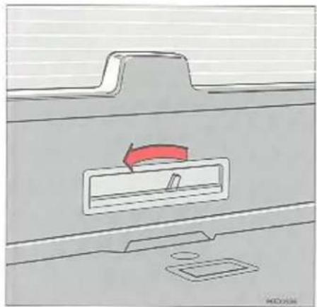
To open the tailgate from the inside of the vehicle, move lever to the left and push outwards.
Child safety lock
Engage the safety lock to prevent children from opening the tailgate from the inside.
A The tailgate can be opened.
B The child cannot open the tailgate from the inside.
Cargo space, Estate
natural_image
Interior view of a vehicle showing the rear compartment with a rectangular vent and internal compartments (no text or symbols visible)Tool box

natural_image
Interior view of a car showing the dashboard, steering wheel, and engine compartment (no text or symbols visible)Spare tyre
Jack

Switch positions
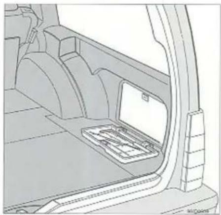
Tool box
The tool box can be released by turning the catch and folding the cover down.
Spare tyre and jack
The spare tyre and jack are located beneath the floor mat in the large storage area.
Always secure the tyre and jack to prevent them from rattling.
Cargo space light
There is an extra courtesy light at the rear of the cargo space.
A Light comes on when the tailgate is opened.
0 The light is always OFF.
B The light is always ON.
Cargo space, Estate

natural_image
Diagram of a car interior showing a seatbelt with a red arrow indicating a downward motion (no text or symbols present)Seat cushion release strap

natural_image
Interior view of a car showing a closed trunk and a briefcase with a red arrow pointing to the door (no text or symbols visible)Backrest release lever
natural_image
Interior view of a car showing a red highlighted seatbelt mechanism (no text or symbols)Latches fit into holes
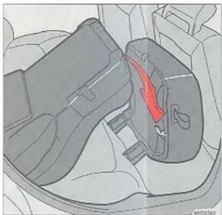
Folding rear seat down Extending luggage area
- Straighten front backrests if they are tilted too far to the rear.
- Pull the seat cushion release strap and swing the cushion up and towards the back of the front seats.
- The rear seat is split: each section can be folded down independently.
-
Move the backrest release lever upwards and fold the backrest forwards.
NOTE: Make sure that the latches on the underneath of the seat cushions engage the holes on the top edges of the backrest. -
The outer seat headrests retract automatically into the backrest, and do not need to be lowered manually. Lower the centre seat headrest if necessary.
- When you put the backrest and seat cushions up again, the headrests will return
to their original position (if they were high up, you will need to lift them the last little bit of the way yourself).
Check that the red locking marks are no longer visible. This means the backrest is properly locked in the upright position. Make sure too that the seat belts are not caught.

WARNING!

The red lock indicator on the backrest lock shows that the backrest is unlocked. When it is covered by the lock release button, the backrest is locked in position. Driving with the backrest un-locked increases the risk of damage when braking hard or in the event of a collision.
Cargo space, Estate

natural_image
Mechanical assembly diagram showing a belt switch mechanism inside a vehicle (no text or labels)Lift the seat cushion out of the hinges
natural_image
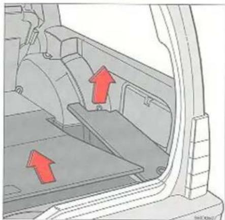
Diagram of a vehicle interior showing structural components with red arrows indicating movement or force (no text or symbols present)There are three concealed storage compartments under the floor.
The lid of the largest compartment is hinged.

natural_image
Technical diagram of a vehicle interior showing structural components and red directional arrows indicating movement or force (no text or labels)Always secure cargo
Removing seat cushions
The seat cushion can be easily removed to provide a slightly larger cargo storage area. To remove: Lift the seat cushion out of the hinges.
Storage compartments
Securing cargo
As a safety precaution, the cargo space is equipped with six eyelets to which straps can be attached to secure luggage. Suitable straps and a cargo net can be purchased from your Volvo dealer.
WARNING!

Do not place heavy objects against the front seats as the backrest which is folded down is then placed under severe strain. Do not load luggage higher than the seat backrests to avoid luggage being thrown forward and injuring passengers in the car. All items should be secured in place.
Seat belts
Seat belts should always be worn
Even abrupt stops can result in serious consequences if you or your passengers do not use the seat belts.
Ask all passengers to use the belts. Remember that if an accident happens, unbelted rear seat passengers will be thrown forward against the front seats which will then be placed under considerable strain, much more than they are intended to take. As a result all occupants may be seriously injured.
Adjusting shoulder belt

natural_image
Illustration of a sword being cut with red arrows indicating motion, no text or symbols presentLap belt low on hips
To fasten:
Pull the belt slowly from the holder and insert the belt tongue into the buckle until you hear a snap and feel the latch engage.
The belt allows greater freedom of movement but the reel locks the belt immediately:
- if the belt is pulled too quickly
- when braking and accelerating
• if the car is at a very sharp angle
• during hard cornering.
Do not recline the backrest too far to the rear. The seat belt is designed to offer protection at normal backrest angles.
To ensure maximum protection it is important that the belt is adjusted to a snug fit.
Remember:
• The belt must not be twisted.
- The lap belt must be positioned low on the hips (not pressing against the abdomen).
- Adjust the fit of the lap belt by pulling the shoulder portion of the belt as illustrated.
- Do not use fasteners or anything else that may hinder the belt from sitting snugly.
Each belt is intended for one person only.
To release:
Press in the red button and allow the belt to retract fully into the holder.
WARNING!

If the seat belt has been subjected to an extreme load – a collision for example – the entire seat belt including reel, anchorages, screws, catches and tensioner lock is to be replaced. Even if the seat belt appears undamaged, some of its protective properties may have been lost.
Replace the belt if it is worn or damaged. Never carry out any adjustments or repairs yourself; let a Volvo workshop do them!
Seat belts
Seat belt check
You can check the seat belt locking function by grasping hold of the belt and jerking it firmly.
The seat belt should not be able to be pulled out!
Check that the seat belt does not fray against sharp edges and make sure that the belt is generally in good condition.
Use water and a synthetic detergent to clean soiled seat belts.
Note! The use of seat belts is required by law in certain countries.

natural_image
Interior view of a car seat with a red upward arrow indicating motion, and a close-up inset showing a person's head (no text or symbols)Adjust the height of the head restraint
Head restraint, rear seat
The height of the head restraint should be adjusted to suit the height of the passenger. If an integrated child cushion is used, the head restraint should be adjusted to suit the position of the child's head against the seat back. See also page 2:25.
Child safety
Child safety
Children should also sit comfortably and safely in the car.
An adult with his seat belt fastened in a Volvo is assured of good protection in the event of an accident.
Your children can also be well-protected if you keep the following points in mind: Remember that all children, irrespective of age and size should be safely restrained in the car. Children should never sit on passengers' laps.
The size and build of the child determines the most effective type of protection.
The extra seat for use in the luggage compartment of the estate is designed for 2 children weighing up to 40 kilos each.
Note: Find out the regulations existing in your country regarding children in cars.
WARNING!

Never use the child safety seat in the front seat in cars fitted with SRS (Airbag) on the passenger side.

Placing in the front seat
natural_image
Diagram of car seat assembly with red directional arrows indicating movement (no text or labels)Placing in the rear seat's outer positions
Children aged up to about 3
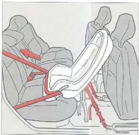
Even new-born babies can sit safely in Volvo's child safety seat. This seat is approved for use in the front seat facing rearwards, in combination with a special installation kit and the car's standard 3-point seat belt (for children weighing up to 18 kg) and in the rear seat's outer and centre positions (for children weighing between 9 and 18 kg).
A baby booster cushion fits easily into the child safety seat to keep small children securely in place.
On certain markets, two mounting eyelets are factory-fitted in the front seat. One of these cyclelets (the left one) is hidden under the carpet.
Find this eyclet and expose it by making a slit (see illustration) with a sharp knife.
When fitting the attachments and anchorage straps to the child seat, please take particular care to follow the instructions included with the child seat in order to obtain maximum safety.
The child seat's attachments are fitted to the car seat's slide rails. For installation in the rear bench, it is also necessary to fit a support to the child seat.
Child safety

natural_image
Interior view of a car seatbelt with red safety belt (no text or symbols)Rear seat centre position

natural_image
Illustration of a person seated in a car seat using a red safety belt, no text or symbols presentChild booster cushion and backrest

natural_image
Illustration of a person seated in a car seat, wearing a red seatbelt (no text or symbols present)Child booster cushion
Anchor the child seat by threading the securing strap through the cyclelets, lock it in the anchorage catch and pull tight. Fasten the lap strap to the child seat hooks. Tighten by pulling the shoulder strap.
NB! When installing the child seat, take particular care to always follow the installation instructions so as to ensure maximum safety.
Children aged 3 and older
When a child grows out of the child seat, this seat should be replaced by a booster cushion placed in either the rear or front seat, utilising the car's standard inertia reel seat belts, preferably in combination with a backrest. Volvo's own child booster cushion, backrest (approved for children weighing between 15 and 36kg ) and 3-point seat belt are all specially designed to offer an excellent degree of safety. When installing a child booster cushion and backrest, please take particular care to follow the instructions which accompany these items, so as to ensure the greatest possible degree of safety.
Place the booster cushion and backrest in either the rear or front seat. Place the child on the cushion, thread the lap belt under the cushion's corners so that the diagonal strap is correctly positioned across the shoulder. Insert the seat belt's tongue into the lock and pull the belt tight so that it fits snugly against the child's body.
Child safety

natural_image
Illustration of a person using a red cable buckle to tie with a white seatbelt, showing no text or symbols.Attachment of the booster cushion
Check that the belt is positioned correctly across the shoulder and that the lap belt is positioned low down so as to offer the best possible protection. The belt should not touch the child's neck, nor should it be positioned below the shoulder.
If a backrest is used, the diagonal strap should run freely in the backrest's corner section.
WARNING!

Never use the child safety seat in the front seat in cars fitted with SRS (Airbag) on the passenger side.
Important hints!
When using other makes of child safety equipment which are available on the market, it is important that you read the installation instructions which accompany these products and follow them closely. Here are a few points to bear in mind:
- The child safety seat must always be fitted in the manner described by the manufacturer.
- Never attach the child seat's anchorage straps to the car seat's longitudinal slide rail, springs or other rails or members under the seat if these have sharp edges.
- Ensure that the child seat's backrest is supported against the instrument panel.
- Do not let the upper edge of the child seat come into contact with the windscreen.
Note! If you have any difficulty in fitting child safety equipment, please contact the manufacturer of this equipment to obtain clear instructions.

natural_image
Illustration of a woman seated in a chair using a red belt, no text or symbols presentLap belt low on hips
Pregnant women
Pregnant women should always wear seat belts. Remember that the belt should always be positioned in such a way as to avoid any possible pressure on the abdomen. The lap portion of the belt should be located low, as shown in the above illustration.
Child safety

natural_image
Illustration of a child wearing a red seatbelt inside a car seat, with an inset showing the same seatbelt (no text or symbols present)Integrated child cushion for children weighing between 15 and 36 kg
Booster cushion
Volvo's own integrated child cushion for the middle seat is specially designed to offer the very highest degree of safety. In combination with the 3-point seat belt, it is approved for children weighing between 15 and 36kg .
When a child is strapped in, the lap section of the 3-point seat belt must run through seat belt guide B (if this type of child seat is fitted) and fit over the child's pelvis – not across the stomach. See illustration.
Remember also to adjust the height of the head restraint to support the child's head. For cleaning instructions see page 6:8.
Folding away the booster cushion
Fold away the seat until you hear a click.
WARNING!

If the integrated child cushion has been subjected to severe strain, for instance in connection with a collision, the entire child cushion including the seat belt and its anchoring screws must be replaced with new components. Even if the child cushion appears to be undamaged, its protective capability might be impaired. It is also necessary to replace the child cushion if it is very worn or damaged. Note, however, that replacement of the child cushion must be carried out professionally since proper installation is crucial to occupant safety. We therefore recommend that any replacement and repairs which may be necessary, be carried out by an authorised Volvo workshop. If the cushion needs to be cleaned, this should be done on the spot. If, however, the cushion cover is so dirty that it needs to be washed separately, the above instructions for cushion installation must be followed.
WARNING!

The ordinary rear centre armrest must not be used as a booster cushion for children. Only Volvo's integrated booster cushions should be used.
Airbag (SRS) SIPS bag

natural_image
Top-down view of a Volvo car steering wheel (no text or symbols on the diagram itself)The airbag is mounted in the hub of the steering wheel and marked 'SRS'

The airbag is mounted above the glove compartment and marked 'SRS'
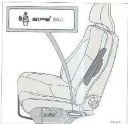
The side impact airbags are fitted in the driver and passenger seat backrests
SRS (airbag) and SIPS (side impact airbag)
For added safety and to supplement the ordinary three-point seat belt, your car is equipped with an airbag (SRS). 'SRS' is embossed on the hub of the steering wheel and on the dashboard in front of the passenger if the car is fitted with an airbag on that side. The inflatable airbag is folded in the centre of the steering wheel. On the passenger side, it is folded into a compartment above the glove compartment. The SIPS bags (side impact airbags) further increase interior safety. If the car is fitted with SIPS bags, 'SIPS' is marked on the side compartment of the front seat. The side impact airbags are fitted in the backrests of both the front seats. The airbags inflate in the event of a sufficiently violent collision. The angle of the collision, speed and nature of the other object also play a part in determining whether the airbag is deployed. The SIPS bags are only deployed in the event of side-on collisions (the same determining factors as above apply). Read more about this on page 2:27. 2:26
WARNING!

The airbag (SRS) is intended to supplement, not replace, seat belts.
The side impact airbags (SIPS bags) are intended as a supplement to the existing SIPS® system. For maximum protection, always wear your seat belt.
* Side Impact Protection System
Airbag (SRS) SIPS bag
The SRS System (airbags in the steering wheel and in the dashboard)
This system consists of a gas generator (1) surrounded by the inflatable airbag (2). In the event of a sufficiently violent collision, a sensor (3) activates the gas generator's detonator and the airbag inflates at the same time as it heats up. To cushion the impact, the airbag deflates when compressed. This also releases some smoke into the car. The entire sequence from inflation to deflation of the airbag takes a few tenths of a second.
Seat belts with seat belt tensioners
Cars with airbags (SRS) have special pyrotechnical seat belt tensioners (4). A small charge which is housed next to the seat belt reel is triggered together with the airbags at the moment of collision tensioning the seat belt to take up the slack caused by loose clothing, etc.. This allows the seat belt to restrain the driver and passenger more quickly.
SIPS bag system (side impact airbags)
This system consists of a gas generator (4), a mechanical sensor (3), pyrotechnical wiring (2) and an airbag (1). A sufficiently violent collision will activate the sensor which in turn triggers the gas generator and inflates the side impact airbag. The airbag inflates between the person and the door panel and absorbs the impact at the moment of collision at the same time as it starts to deflate. The SIPS bag for the front seats work independently of each other.
WARNING!

Never drive with the airbags deployed. They can impair the steering of your car. Other safety systems can also be damaged. The smoke and dust formed when the airbags are deployed can cause irritation or damage to your skin and eyes in the event of prolonged exposure. If this occurs, rinse with cold water and/or contact your doctor. Friction injuries may be caused by the rapid deployment of the airbags in combination with the material of the airbags.

- Gas generator
-
Airbag
-
Sensor/diagnostic unit
- Seat belt tensioner
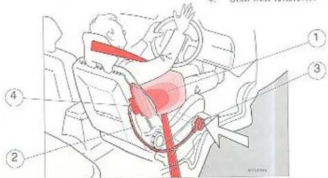
- Airbag
- Sensor
- Gas generators
- Pyrotechnical wiring
Airbag (SRS) SIPS bag

The warning lamp in the combined instrument
The SRS system is continually monitored by the sensor/diagnostic unit. In the combined instrument, there is a warning lamp marked 'SRS'. This lamp comes on with the other lamps when you start the engine and should go out when the motor is running. Even if you only switch on the ignition to position II, the lamp should still go out after about 10 seconds.

Label on seat belts with seat belt tensioners
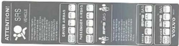
This decal is located on the door pillar
The year and the month shown on the decal on the door pillar(s) indicate when you should contact your Volvo workshop for a specific inspection and, if necessary, replacement of airbags and seat belt tensioners. Never attempt to make any adjustments to the SRS or SIPS bag systems yourself. Please contact your Volvo dealer if you have any queries regarding either of these systems.
WARNING!

If the warning lamp stays on or comes on when the car is being driven, it is an indication that the SRS system is not working properly. If this happens, contact your nearest Volvo workshop immediately.
WARNING!

Never attempt to repair any part of the SRS or SIPS bag system yourself. Any interference with the system may cause it to malfunction and result in serious injury. Work on the system may only be carried out by an authorised Volvo workshop.
Airbag (SRS) SIPS bag

natural_image
Line drawing of a person seated in a car, viewed from the side, with no visible text or symbols.Inflation of airbag on passenger side
Passenger's SRS (Airbag)
When the airbag on the passenger side is inflated, it has a volume of approximately 135 litres, while the airbag on the driver's side has a volume of only approximately 65 litres because of the position of the steering wheel. Both airbags provide the same degree of protection in the event of a collision.
WARNING!

Passenger's SRS (Airbag)
- Front seat passengers must never lean over the dashboard, sit on the edge of the seat or in an awkward position. Passengers should sit comfortably, upright and with their backs against the seat back. Seat belts should be properly fastened.
- Always keep your feet on the floor (not on the dashboard, on the seat, in the door pocket of the glove compartment or out of the window).
- Never allow children to stand or sit in front of the passenger seat.
- Never use the child seat or booster cushion in the front seat if your car is fitted with an SRS (Airbag) on the passenger side.
- No objects or accessories should be placed on or attached to the SRS panel (above the glove compartment) or near to it, or in the area filled by the inflated airbag.
- Do not leave loose articles on the floor, seat or dashboard.
- Do not interfere with SRS components in the hub of the steering wheel or on the panel above the glove compartment. SRS components may only be replaced by an authorised Volvo workshop.

WARNING!
Do not attach any labels or decals on the steering wheel or on the dashboard.
WARNING!

SIPS bag
- Only Volvo Genuine upholstery or upholstery approved by Volvo for the SIPS bag may be used on the front seats of cars equipped with SIPS bags.
- No objects or accessories may be placed in the area between the outer edge of the seat and the door panel as this area is affected by deployment of the SIPS bag.
- Never attempt to make any adjustments to the SIPS bag system in the front seats. Replacement of SIPS bag components may only be carried out by an authorised Volvo workshop.
Airbag (SRS) SIPS bag
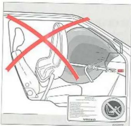
The airbag and child seat do not go together! SRS text at the edge of the dashboard
Child seat and child booster cushion
Serious injury may occur if the child seat or child booster cushion is placed in the front passenger seat in a car fitted with a passenger airbag.
The rear seat is the safest place for child seats/booster cushions in a car fitted with a passenger airbag and child safety seats.

SRS text on the dashboard
WARNING!

SIPS bag
Never place a child seat or child booster cushion in the front passenger seat if the car has an airbag (SRS) on the passenger side.

Inflation of SIPS bag
SIPS bag
The SIPS bag system is a mechanical system comprising two main parts: the side impact airbag and the sensor unit. The side impact airbag is fitted in the driver and passenger seat backrests, while the sensor unit is located at the outer edge of the seat nearest the door. The sensor is not monitored by the SRS system's sensor as the SIPS bag system is a mechanical system. When inflated, the side impact airbag has a volume of about 12 litres.
Airbag (SRS) SIPS bag
When are the airbags deployed
In a collision, the sensor in the SRS system reacts partly to the forces which are activated during a collision and partly to the deceleration caused by the collision. The sensor determines whether a collision is sufficiently violent to activate the airbags.
It should be noted that it is not the deformation of the bodywork which affects the car's sensor but the rate of deceleration at the moment of collision. The SRS sensor reacts when people travelling in the front of the car are at risk of being injured through contact with the dashboard or steering wheel.
The above also applies to the SIPS bag system and the side impact airbags, except that the side impact airbags only inflate in the event of side-on collisions, when the car collides with enough force with a fixed or heavy object in the area covered by the SIPS system.
NOTE! The SRS and SIPS bag systems can only be activated once in a collision.
If the airbags have been deployed, we recommend the following:
- Have the car towed to a Volvo workshop. Even if the car can be driven after an accident, we recommend that you do not drive once the air bags have been deployed.
- Have an authorised Volvo workshop change the SRS and SIPS bag system components.
- Only Volvo Genuine parts should be used to replace SRS and SIPS components (airbags, seat belts with seat belt tensioners, etc.).
The heart of Volvo's safety system
The three-point seat belt is the heart of Volvo's safety system! Seat belts should be worn at all times by everyone in the car. The SRS system is a supplement to the three-point seat belt. The SIPS bag system with side impact airbags is a supplement to the regular SIPS system in the bodywork.
WARNING!

The sensor for the SRS system is located on the floor under the driver's seat. If the floor of the passenger compartment becomes flooded, disconnect the battery leads in the engine compartment. Do not attempt to start the car, as this may activate the airbag. Have your car towed to your nearest authorised Volvo workshop.
Cargo space 5-door model. Loading

natural_image
Interior view of a car showing the rear compartment with a red arrow pointing to a box labeled '汽车' (car), no text or symbols present.Load the cargo against the backrest

natural_image
Line drawing of a car trunk with a cardboard box placed inside (no text or symbols)Load both halves of the backrest

natural_image
Diagram of a car interior showing a driver with two wheels and red guide rails (no text or symbols)Tie down the cargo
Loading in loading area
Seat belts and airbags give driver and passengers good protection, especially in head-on collisions. However, there is also a risk of injury from behind. When loading the car, remember that objects not properly loaded and secured may move forward in collisions or when braking suddenly, causing serious injury.
Remember that a 20 kg object weighs the equivalent of 1,000 kg in a head-on collision at 30 mph (50 km/h).
Remember the following when loading the car:
- Load the cargo against the backrest.
- Load heavy cargo as low down as possible.
- Load wide cargo on either side of the rear seat split.
- Secure the cargo with cargo straps through the eyelets in the cargo space.
- If nobody is sitting in the rear seat reinforce the backrest by fastening the rear seat belts.
- Never load cargo above the backrest without a cargo net.
Luggage compartment, 5-door model - Cargo net
natural_image
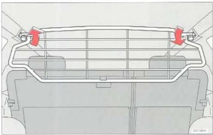
Top-down technical diagram of a vehicle front panel with red arrows indicating directional components (no text or symbols)Cargo net
Your car can be fitted with a cargo net as an optional extra. The cargo net prevents cargo and animals being thrown forward should you brake hard. The cargo net can be folded up into the roof when not in use.
Cargo net and extra rear-facing child seat
If your car is also equipped with an extra rear-facing child seat in the luggage compartment, you must, without exception, remove the cargo net before using the child seat. Otherwise, in the event of hard braking, the child could be seriously injured and the rescue services could be prevented from accessing the luggage compartment.
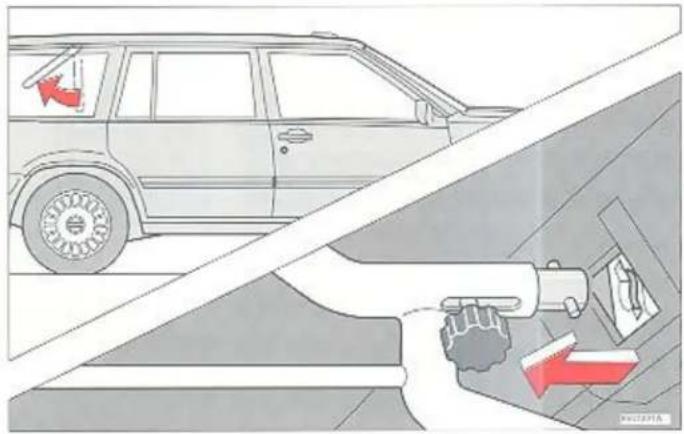
When removing the cargo net:
- Lean the cargo net back
- Disconnect the two knobs on the cargo net and push them towards the centre.
- Remove the cargo net.
- When installing the cargo net, reverse this procedure.
Luggage compartment, 5-door model - Luggage cover

natural_image
Interior view of a car showing the rear seat, rear seats, and dashboard (no text or symbols visible)
natural_image
Technical line drawing of a mechanical assembly with a red arrow indicating direction (no text or symbols)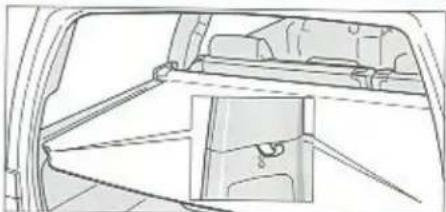
natural_image
Technical line drawing of a vehicle rearview structure showing structural components (no text or symbols)
natural_image
Illustration of a hand pressing down on a mechanical component with a red arrow indicating force or motion (no text or symbols present)Luggage cover
Your car can be fitted with a luggage cover as an optional extra. The pull-out luggage cover is like a blind behind the rear seat. Pull it out and attach it at the rear of the luggage compartment to conceal the cargo and keep it out of sight. (See picture.)
Removing luggage cover (see picture)
If, as a result of the size of the cargo, you want to remove the luggage cover temporarily:
- Push the end of the luggage cover towards the middle
• Pull the luggage cover backwards - When installing, reverse this procedure.
Child Restraint Anchorages (Australia)
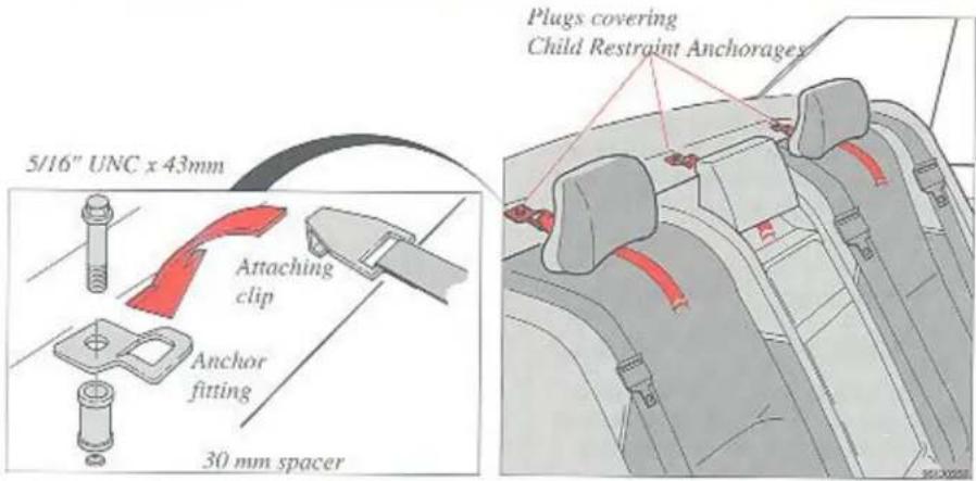
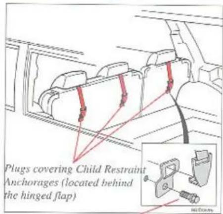
5/16" UNC x 30mm
To comply with Australian requirements all Volvo cars in the market are fitted with Child Restraint Upper Anchorages in the rear seat. The reason for this legislation is to provide upper anchorages for the attachment of Child Restraints and facilitate the transfer of Child Restraints from one car to another, since they would have similar upper restraint anchorages fitted as standard.
During the model year one anchor fitting will be factory-installed in the middle section of the parcel shelf on sedans and in the middle section of backrest on estate wagons.
Location of anchorages: Sedan – three anchorages under the parcel shelf. Estate – three anchorages on the rear of the backrest.
WARNING!

Child Restraint Anchorages are designed to withstand only those loads imposed by correctly fitted Child Restraints. Under no circumstances are they to be used for adult seat belts, harnesses or for attaching other items to the vehicle.
Remove the plug covering the anchorage point you want to use. This can be done with a suitable coin. The plug is removed anticlockwise. Refer to the child seat manufacturer's instruction for securing your child seat. The anchor fitting to be installed has to be of the same type as shown in the diagrams above. For correct installation: Note the correct fittings and dimension in the diagrams. It is important to use only the recommended bolt and spacer. For sedan unique bolts and spacers are found in the vehicle's glove box. Additional bolts and spacers may be obtained from your Volvo dealer.
Seat belts
To comply with Australian requirements the following additional information should be read in conjunction with the seat belt information.
WARNING!

Seat belts are designed to bear upon the bone structure of the body, and should be worn low across the front of the pelvis or across the pelvis, chest and shoulders, as applicable; wearing the lap section of the belt across the abdominal area must be avoided.
Seat belts should be adjusted as firmly as possible, consistent with comfort, to provide the protection for which they have been designed. A slack belt will greatly reduce the protection afforded to the wearer.
Care should be taken to avoid contamination of the webbing with polishes, oils and chemicals, and particularly battery acid. Cleaning may safely be carried out using mild soap and water. The belt should be replaced if webbing becomes frayed, contaminated or damaged,
It is essential to replace the entire assembly after it has been worn in a severe impact even if damage to the assembly is not obvious.
Belts should not be worn with straps twisted. Each belt assembly must only be used by one occupant; it is dangerous to put a belt around a child being carried on the occupant's lap.
WARNING!

No modifications or additions should be made by the user which will either prevent the seat belt adjusting devices from operating to remove slack, or prevent the seat belt assembly from being adjusted to remove slack.
Starting and driving
Starting and driving
Refuelling, running-in 3:2
Economical driving 3:3
Starting the engine 3:4
Manual gearbox 3:5
Automatic transmission 3:6
Road handling, overheating 3:19
Cruise control 3:10
Towing 3:11
Jump starting 3:12
Brakes 3:13
Winter driving 3:14
Towing a caravan 3:15
Long distance trips 3:17
Refuelling

natural_image
Technical line drawing of a mechanical component with no visible text or symbolsCars with catalytic converters are equipped with a restricted fuel tank opening
The fuel cap is located behind the cover on the left-hand wing. Place the cap in the bracket on the inside of the cover when refuelling.
Open the cap slowly during hot weather to release the fuel's vapour pressure. Do not overfill the tank with fuel. Do not allow the fuel pistol to shut off automatically more than three times. After refuelling screw on the cap until a click is heard.
Your Volvo dealer has locking caps to suit all Volvo models.
Your new car – slippery roads
Driving on slippery roads will feel different in a car with a manual gearbox from one with an automatic gearbox. Practise driving on slippery roads in controlled conditions to see how your new car reacts.
Running-in
During the running-in period the following speeds should not be exceeded.
| 600 miles(1000 km) | 600-1200 miles(1000-2000 km) | |
| 1st gear | 20 mph (30 km/h) | 25 mph (40 km/h) |
| 2nd gear | 30 mph (50 km/h) | 45 mph (70 km/h) |
| 3rd gear | 50 mph (80 km/h) | 60 mph (100 km/h) |
| 4th gear | 70 mph (110 km/h) | 80 mph (130 km/h) |
| 5th gear | 80 mph (130 km/h) | 80 mph (130 km/h) |
Do not drive at low speeds in top gear and avoid depressing the accelerator pedal fully to change down (kick-down) on cars with automatic transmission during the first 1200 miles (2000 km).
Use the correct petrol
A car equipped with a catalytic converter must always be run on unleaded petrol so as to avoid damage to the catalyst. Recommended petrol octane rating is 95 RON.
Some petroleum companies use cleaning additives in the petrol they supply. The purpose of these additives is to reduce the risk of the formation of deposits in the engine, which would reduce driveability and performance. If you are uncertain as to whether the petrol you use contains these additives, please ask the personnel at Volvo.
NB! Do not add any cleaning additives unless you have been expressly advised to do so by an authorised Volvo workshop.
If you intend driving to countries where it is difficult to obtain unleaded petrol or petrol with a satisfactory octane rating, please contact your Volvo workshop.
Economical driving
Better driving economy can be effected by thinking ahead, avoiding rapid starts and stops and adjusting the speed of your vehicle to immediate traffic conditions. Observe the following rules:
- Bring the engine to normal operating temperature as soon as possible by driving without hard acceleration. A cold engine uses more fuel and is subject to increased wear.
- When possible avoid using the car for driving short distances. This does not allow the engine to reach normal operating temperature.
- Drive carefully and avoid rapid acceleration and hard braking.
- Do not exceed speed limit.
- Avoid carrying unnecessary items (extra load) in the car.
- Check tyre pressure regularly – cold tyres.
- Remove snow tyres when threat of snow or ice has ended.
- Note that roof racks, ski racks, etc., increase air resistance and thereby fuel consumption.
Utilizing the gears correctly will also improve fuel economy.
- Change from 1st to 2nd at approx. 10 mph (20 km/h)
Change from 2nd to 3rd at approx. 20 mph (35 km/h)
Change from 3rd to 4th at approx. 30 mph (50 km/h)
Change from 4th to 5th at approx. 45 mph (70 km/h).
- Avoid using the automatic transmission kick-down unless necessary.
Vehicle condition
Keep the body and engine clean. Other factors which help to decrease fuel consumption are:
- clean spark plugs
• correct ignition setting - clean air filter
- correct valve clearances
- correct idle speed (constant idle speed, certain models)
- correct engine oil, oil change interval and filter
• correctly set fuel injection system
• correctly adjusted brakes
• correct front end alignment
• correct tyre pressures.
Do not forget that the most important factor affecting fuel economy is you, and the way in which you use the accelerator, brakes and gearbox.
Warning! Catalytic converter

The catalytic converter has a working temperature of several hundred degrees. Do not park your car over flammable materials (e.g. high grass) which could be ignited by contact with the converter.
Starting the engine
Starting the engine
Injection engine
1 Apply the parking brake (handbrake).
2 Manual gearbox: Move the gear lever into neutral.
Press the clutch pedal.
Automatic transmission: Move the gear selector lever to position P or N.
3 Do not touch the accelerator pedal.
4 Turn the ignition key to the starting position.
If the engine does not start within 5 to 10 seconds, release the key and try once more.
Never race the engine directly after a cold start.
If the engine does not start or misfires contact your Volvo dealer.
A car equipped with a catalytic converter should never be tow-started. The function of the catalytic converter may be impaired if this instruction is not observed.
Starting en engine with an electronic start inhibitor
The engine is started in the normal manner. If the wrong key is used, the engine stops after 2 seconds. If the key is held in the Drive position for more than 4 minutes, the key must be turned back and the engine started again.
Cold-starts at high altitude
Cold-starts at high altitude (above 5900 ft. / 1800 m) can be made easier by pressing the accelerator pedal half-way and keeping it there, before the ignition key is turned to the starting position (item 4 above).
When the engine starts and engine speed increases, gradually release the accelerator pedal.

CAUTION CARBON MONOXIDE!
If you park your car in the garage, always open the garage doors fully before starting the engine. Exhaust gases contain carbon monoxide which is odourless but potentially lethal.
Manual gearbox M-90
Reverse gear inhibitor M-90
There is an inhibitor to prevent reverse gear being unintentionally engaged when changing down from 5th to 4th gears. This inhibitor is always engaged when the gear shift is pushed forward towards 5th gear. The inhibitor is disengaged when the gear shift is moved to neutral (between 3rd and 4th).
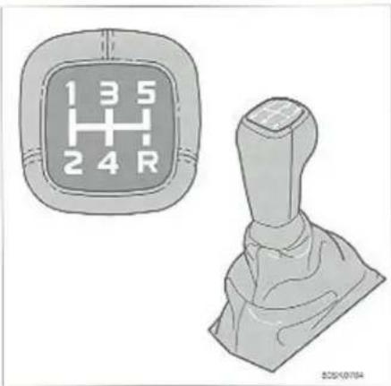
Gear positions

Reverse gear catch
Gear positions, manual gearbox
Depress the clutch pedal fully when changing gear.
Remove your foot from the clutch pedal while driving.
In order to obtain the best possible fuel economy, try to use 5th gear as often as possible in highway driving at more than approx. 45 mph (70 km/h).
In order to avoid unnecessary wear and tear on the gearbox, follow the gear pattern on the gear lever. For instance, do not change directly from second to fifth gear.
Reverse gear catch
The gear lever must first be moved to neutral in order to engage reverse gear. Reverse gear is fully synchronised and can be engaged even though the car is not at a complete standstill.
CAUTION!
Reverse gear should not be engaged if the vehicle is moving forward.

Automatic transmission

AW
gearbox
Selector lever
P Park
Select this position when you start the engine or park the car.
This position locks the rear wheels and the transmission whether or not the engine is running.
The car must be at a complete standstill before selecting P.
Use this position when parked but apply the parking brake as well when parked on an incline.
R Reverse
The car must be fully stopped before shifting into or out of R.
N Neutral
The N position is neutral, i.e. no gear is engaged. The engine can be started. Use the parking brake.
D Drive
The normal driving position is indicated by D. Changing up and down between the transmission gears takes place automatically depending on acceleration, load and road speed.
Lock-up function
Vehicles with automatic transmission have a locking clutch which disengages the torque converter when D is selected and road speed exceeds 45–65 mph (75–110 km/h). It reduces engine speed and improves fuel consumption. When accelerating quickly the lock-up effect is very like an additional gear change.
WARNING!

Never alight from the car when the engine is running. If by mistake the gear selector is moved from P the car may start moving.
2 Second
Changing up and changing down of first two gears occurs automatically. No upshift to 3rd gear occurs. Position 2 can be used for
- driving in hilly terrain
- increased engine braking.
1 First
If position 1 is selected when driving at high speeds, 2 is engaged first and 1 when the speed has dropped to approx. 30 mph (50 km/h).
Note: No upshift can occur once 1 is engaged.
Use position 1 to select low gear with no changing up. For instance, when starting down steep gradients.
Selector lever operation

Push-button and 4th speed indicator lamp
By pressing the button on the side of the gear selector you can switch between 3rd and 4th speeds.
An indicator lamp on the dashboard lights up when 4th speed is disengaged, as a reminder that the transmission is operating as a 3-speed unit.
To change back to a 4-speed unit, depress the button again – the light will go out.
It is advisable to disengage 4th speed when: - towing a caravan or trailer
- driving in hilly terrain.
But use 4th speed as much as possible in all other driving conditions as fuel economy is improved.
Kick-down
For automatic shift to a lower gear depress the throttle pedal briskly to its limit.
Changing up will occur as the top speed for a particular gear is approached or by releasing the throttle pedal slightly. Kick-down can be used for maximum acceleration or when overtaking.
Remember that the transmission only reverts to a 4-speed unit after the accelerator is released.

Selector knob positions
Selector lever operation (AW)
The gear selector can be moved freely between D and 2. The other positions are separated by a lockout which is operated by depressing the selector knob.
Depressing the selector knob slightly allows selection of positions N, D, 2 and 1.
Depressing the selector knob fully allows selection of positions R and P.
- Never select P or R when the vehicle is in motion.
- When initially selecting positions D, 3, 2,1 or R the vehicle should be standing still with the engine idling.
- The selector lever must not be moved to position 2 or 1 at speeds in excess of 80 mph = 125 km/h
Automatic transmission
Starting
1 Move the selector lever to P.
2 Start the engine by turning the ignition key.
3 Depress brake pedal
4 Move the selector lever to the desired driving position. Wait – there is a slight delay before the gear is engaged, especially reverse gear.
5 Once the vehicle begins to "creep", release the brake and depress the accelerator.
Select position N to prevent the gearbox overheating during long periods of waiting with the engine running (e.g. traffic jams).
Towing a caravan or trailer Automatic transmission
- For steep hills and when driving for prolonged periods at low speeds, position 1 should be selected. However, avoid repeated changes since this can cause overheating of the gearbox oil. For driving on mountain roads with long uphill gradients, select position 2.
- When negotiating long, steep downhill slopes, position 1 should be selected and position 2 for less severe inclines, in order to obtain the best possible engine braking effect.
- Do not hold the car stationary on an incline by using the accelerator pedal, engage the hand brake instead. This prevents the gearbox oil from overheating.
Points to remember
Weight distribution affects handling
At the specified kerb weight your car has a tendency to understeer which means that the steering wheel has to be turned more than seems appropriate for the curvature of the bend. This ensures good stability and reduces the risk of rear wheel skid. Remember that these properties can alter with the load. The heavier the load in the boot, the smaller the tendency to understeer.
Handling, road holding and tyres
Tyres play an important part in the handling and road holding of a car. The type of tyre (radial), size and pressure are important for proper handling. When fitting new tyres, it is therefore very important to fit tyres of the same size and type (and preferably made by the same manufacturer) as those previously fitted, and follow the recommendations concerning tyre pressures on 4:3.
Do not drive with the boot open
If you drive with the boot open, exhaust gases (including carbon monoxide) may be drawn into the car. To prevent this risk:
- Close all windows
- Move the heater control to ↑ and switch the fan to full speed, 5.

Overheating
You increase the possibility of overheating the cooling system in hot weather if:
- you drive up long steep inclines at full throttle towing a trailer.
- the car is allowed to idle with the air conditioning switched on.
- you switch off the engine directly after driving at high speed.
- if you fit extra lamps in front of the grille.
To avoid overheating:
Reduce speed if you are towing a trailer up long steep inclines. Also switch off the air conditioning for a while.
- Do not let the engine idle unnecessarily.
- Do not turn off the engine immediately when you stop after high speed driving.
Automatic differential lock\*
The differential automatically locks at speeds between 3–25 mph (5–40 km/h) if either of the drive wheels begins to lose traction.
The differential lock improves power distribution to the drive wheels in slippery conditions, shifting power to the wheel with best traction. It also functions when the transmission is in reverse.
Engagement and disengagement of the differential lock takes place automatically.
* Certain markets
WARNING!

An extra mat on the driver's floor may cause the accelerator pedal to catch. Check that the accelerator pedal is not impeded.
Cruise Control

Engagement
The cruise control switches are located on the direction indicator stalk.
To set the desired speed:
1 Set switch (B) in the ON position.
2 Accelerate or decelerate to the desired speed
Note: The cruise control cannot be engaged at speeds below 35 km/h.
3 Press the SET SPEED button (A) to engage the desired speed.
Reducing speed
The cruise control is automatically disengaged if the brake or clutch pedal is depressed. The previously selected cruise speed is retained in the memory; by momentarily pushing switch (B) towards the RESUME setting, that speed will be re-engaged.
Acceleration
Momentary acceleration such as for overtaking does not interrupt cruise control operation. The previous set speed will be maintained without having to set the switch to RESUME. If the cruise control is already engaged, the cruising speed can be increased by holding down the SET SPEED button (A). One short press corresponds to an acceleration of 1.6 km/h. The current speed of the vehicle when the button is released will now be programmed.
WARNING!

The cruise control should not be used in heavy traffic or when driving on wet or slippery roads.
Note: When driving on hills the actual vehicle speed may vary slightly from the set cruise control speed.
If the speed decreases to 70% of the set speed the cruise control will automatically disengage. This also occurs if the wheels spin.
Disengagement
Set switch (B) to the OFF position or depress the brake or clutch pedal. If the ignition is switched off or the gear selector lever is in position N, the cruise control system will automatically disengage. If the speed decreases to 70% of the set speed, the cruise control will automatically disengage. This also occurs if the wheels spin or lock.
Towing

Front towing eyelet

Rear towing eyelet
Towing
The following precautions should be taken if the car has to be towed.
- Unlock the steering wheel.
- In most countries vehicles on tow are subject to regulations regarding towing speed.
- With the engine stopped the brake servo will be rendered ineffective so that approximately four times more pedal pressure will have to be applied when braking. In addition the steering will feel heavier than normal.
- Drive as smoothly as possible. Try to keep the tow-line stretched to avoid unnecessary jerking.
Especially for automatic transmissions
- The gear selector must be in position N, the gearbox correctly adjusted and the oil level correct.
- The highest permitted speed is 20 km/h. Farthest towing distance 20 miles (30 km).
- If unsure about the correct oil level or gearbox adjustment, the car should be towed with the driving wheels off the ground.
- The engine cannot be "bump started". For "jump starting" see next page!
Starting the engine by towing
Cars with automatic transmissions cannot be started by towing.
Cars with catalytic converters must not be started by towing.
(Refer to section on starting with a flat battery.)
Cars with manual gearboxes without catalytic converters.
The towing car is started and driven at a constant speed.
In the towed car:
- switch on the ignition.
- depress the clutch pedal and engage 3rd or 4th gear. Wait until the car picks up speed and release the clutch pedal gradually. As soon as the engine starts, depress the clutch pedal once more.
Towing
NOTE! Towing eyelets should only be used for towing the car on the road. They must not be used for towing cars out of ditches, when professional help should be called.
Jump starting

WARNING!

The battery contains sulphuric acid which can cause serious injury. If the acid comes in contact with the eyes, skin or clothes, flush with large amounts of water. If eyes are affected seek medical attention.
Jump starting
If the battery is flat, you may have to use a charged battery to start the engine. To avoid any risk of explosion, the following procedures are strongly recommended:
• Make sure that the ignition is off.
- Check the voltage of the other battery. It must be 12V.
- If you are using jump leads, make sure that the other car does not touch yours.
- First contact the positive terminal (red lead, P or +) of the other battery (1) to the positive terminal of the discharged battery (2), then connect the black lead to the negative terminal (blue, N or -) of the other car (3). Ensure that there is good contact at the clamps to prevent sparks occurring when attempting to start.
- Connect the other end of this lead to a suitable earth point away from the battery in your car e.g. one of the engine lift eyelets (4).
- Start the engine of the other car and allow it to run for a few minutes at higher than idling speed (around 1500 rpm).
- Start the engine.
Do not move the clamps during start attempts!
Do not lean over the batteries!
• After the car has started, remove the clamps in the reverse order.
Brakes
Should there be a malfunction in a brake circuit, a red warning light will come on
The brake pedal will sink in a little deeper and may feel softer than usual. Some extra pressure will also be required for normal braking.
If the warning lamp lights up while driving or during braking, the brake fluid level is too low. Stop immediately and check the level of fluid in the brake fluid reservoir (see the back cover for location).
If the level is under MIN in any part of the reservoir: do not drive any further but have the car towed to a workshop to be checked and repaired.
The brake servo functions only when the engine is running
If your car is being towed or is coasting to a halt with the engine switched off, then you must depress the brake pedal approximately four times harder than usual because the brake servo is inoperative.
The brake pedal feels hard and unresilient. Diesel engined vehicles are equipped with a separate vacuum pump to maintain sufficient vacuum in the brake servo cylinder. At idle speeds 5–10 seconds are required for a working vacuum to build up. If the brake pedal has been depressed repeatedly with the engine turned off wait a few seconds (without touching the brake pedal) before driving away.
Moisture on brake discs and brake pads may affect braking
Driving in heavy rain or passing through an automatic car wash can cause water to collect on the brake discs and pads. This will cause a delay in braking effect when the pedal is depressed. To avoid this eventuality depress the pedal occasionally when driving. This will remove the water from the brakes. Check that brake application feels normal. This should also be done after washing or starting in very damp and cold weather.
Severe strain on the brake system
The brakes will be subject to severe strain when driving in mountains or hilly areas. The speed is usually low which means that brake cooling is less efficient than when driving on level roads.
To reduce strain on the brakes excessive use should be avoided. Instead, change down into a lower gear and let the engine help with braking. A good rule is to use the same gear driving downhill as would be used driving uphill. For vehicles with automatic transmission use position 2 or in some cases 1. Do not forget that if you are towing a trailer, the brakes will be subjected to more load than is usual.
ABS brakes
The ABS brake system is designed to prevent wheel-locking under severe braking conditions. The system "senses" when the brakes are about to lock and reacts by redistributing brake pressure automatically, thereby preventing the wheels from locking. The ABS system undergoes an automatic self-diagnosis every time the engine is started and at speeds of approximately 6 km/h. At this stage it is possible to feel a slight pulsating throb in the brake pedal. This is entirely normal. A soft clicking noise can also be heard when you accelerate after idling. The ABS system is performing a self-diagnosis.
When the ABS system is activated during braking, you can feel the pulsating throb in the brake pedal and also hear the pulse tones quite clearly. These are perfectly normal ABS characteristics.
Do not release pedal pressure because you can hear and feel the ABS system in operation! Note that you must press on the brake pedal with full force to obtain optimal effect. Bear in mind also that the ABS system does not increase the car's overall braking performance. Instead, the ABS system is designed to let you steer the car under all conditions, giving you better control of your car and therefore a greater degree of safety.
Winter driving
For the onset of winter, take note of the following advice:
- Make sure that the engine coolant contains at least 50% anti-freeze, i.e. 5 litres Volvo glycol additive. This gives protection against freezing down to -35°C. See 7:10.
- Try to keep the fuel tank well filled – this prevents the formation of condensation in the tank. In addition it is worthwhile adding a fuel line de-icer before refuelling.
- Use correct engine oil. The viscosity of the engine oil is important. Oil with low viscosity (thinner oil) aids cold starting as well as decreasing fuel consumption while the engine if warming up. For winter use, 5W-30 oil, particularly the synthetic type, is recommended.
Be sure to use good quality oil but do not use this cold-weather oil for hard driving or in warm weather.
See pages 7:6–7:7 or ask your Volvo workshop for details.
- The battery is subjected to a greater load during winter since the heater, windscreen wipers, lighting, etc. are used more often. Moreover the capacity of the battery decreases as the temperature drops. In very cold weather, a poorly charged battery can freeze and become useless. It is therefore advisable to check the state of charge more frequently and spray an anti-rust oil on the battery poles.
- To prevent the washer reservoir from freezing, add washer solvents containing de-icer. This is most important since dirt is often splashed on the windscreen and headlamps during winter driving, thus requiring frequent use of the washers and wipers.
- Use Volvo lock lubricant or grease in the lock. These can be purchased from your Volvo dealer.
NOTE: Avoid the use of de-icing sprays as these can affect the locking function.
Towing a caravan or trailer
Towing a caravan
- Only approved towing brackets should be used. Information on which types are approved can be obtained from your Volvo dealer.
- Towing brackets which are designed to be attached to the bumper must not be used. The bumpers must on no account be used for fitting towing brackets. Their function is to absorb impacts.
- Certain 5-door models feature the ride-height regulation system, whereby the rear suspension always maintains the same height irrespective of the load currently being carried. The system is activated when the car moves off from standstill.
- Position the trailer's load such that the weight on the car's towbar is approx. 50 kg (for trailer weights under 1200 kg) or 75 kg (for trailer weights above 1200 kg).
Note that the weight on the towbar (50/75 kg) is included in the car's overall load-carrying capacity and that the load in the car's boot may have to be reduced to prevent the car's axle loads and/or overall load being exceeded when towing a trailer. - Increase tyre inflation pressure to values specified under full load and towing in table, see 4:3.
- Clean the towing bracket regularly and grease the towbar head® and all movable parts to avoid unnecessary wear. Grease the nipples on the retractable type towing bracket.
- Do not tow heavy trailers when the car is new. A new car must first be run in i.e. it must have covered at least 600 miles (1000 km).
- The brakes will be subject to more strain when driving in hilly areas. The risk of overheating can be minimized by selecting a lower gear and adjusting the speed of the vehicle to suit.
- If your vehicle is equipped with an automatic transmission refer to 3:8-9 for further information.
-
If driving in a hot climate, trailer weight must not exceed 1500 kg.
-
Since the engine is placed under more load than usual the oil must be changed more often.
Note that the cooling system is also placed under more load than usual when towing. See 3:9. - Highest permitted speed 50 mph (80 km/h).
- Highest permitted trailer weight for trailer without brakes 500 kg.
- Note: The maximum trailer weights and speed limits given are those recommended by the Volvo Car Corporation. Keep in mind that national legal requirements in force in your country could further limit these weights and speed limits.
Extra oil cooler
Note: Some models have automatic transmission systems which do not require an extra oil cooler. Other models have an extra oil cooler mounted as standard equipment. Let your Volvo dealer check if your car needs an extra oil cooler fitting. See next page!
WARNING!

If you fail to follow the stipulated weight and speed limits, the entire car/trailer outfit may be difficult to control in emergency avoidance manoeuvres and during braking, constituting a danger to yourself and other road users.
Towing a caravan or trailer
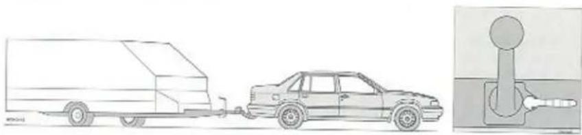
natural_image
Side profile of a car being towed onto a long truck, with a close-up of its right-hand valve (no text or symbols visible)WARNING!

If your car is fitted with a detachable towbar; Ensure that the towbar is locked before setting off. The green handle should be in the horizontal position! See picture!
| Highest permitted trailer weight for trailer with brakes | Weight on the towbar | Volvo's reinforcement kit is required. A vibration damper is recommended. | Cars with automatic transmission: | |
| An extra gearbox oil cooler is recommended | An extra gearbox oil cooler is required | |||
| 0-1200 kg | 50 kg | ● | ||
| 1201-1500 kg | 75 kg | ● | ||
| 1501-1600 kg | 75 kg | ● | ||
| 1601-1800 kg | 75 kg | ● | ● | |
| 1801-1900 kg Germany only See p. 8:3 | 75 kg | Genuine Volvo towbar with reinforcement kit and vibration damper required | ● | |
Long distance trips
It is always advisable to have your car checked by a Volvo dealer before driving long distances. Your dealer will also be able to supply special kits containing bulbs, fuses and wiper blades.
If you prefer to check the car yourself, note the following.
- Check that the engine runs smoothly and that fuel consumption is normal.
- Check the engine oil, coolant levels, and any possible fuel leakage.
- Check transmission oil level and rear axle for leakage.
- Check state of drive belts.
- Check that the battery is properly charged.
- Examine the tyres carefully, the spare tyre as well and replace those that are worn.
- The brakes, front wheel alignment and steering gear should be checked only by your Volvo dealer.
- Check all lights including high beams.
- Check the tool box.
- Warning triangles are legal requirements in some countries.
- Before travelling to countries with right hand traffic, the headlamps should be adjusted to avoid blinding oncoming traffic. For this purpose the triangular section on the headlamp lens should be covered with black tape.
- If you intend to travel to a country where it may be difficult to obtain correct octane petrol or unleaded petrol your engine can be adjusted. Contact your Volvo dealer.
Roof racks
- Use a sturdy roof rack which is designed for your Volvo and can be securely fitted to the car roof.
• Max. roof load 100 kg. - Spread the load evenly over the rack.
- Place the heaviest load nearest the car roof.
- Remember that the centre of gravity of the car alters with the weight of the load on the roof rack, thus changing the driving characteristics.
- Anchor the load securely and recheck during journey.
- Drive smoothly. Avoid rapid starts, hard cornering and abrupt stops.
- Remove the rack when it is no longer needed. This reduces wind resistance and improves fuel consumption.
Wheels and tyres
Wheels and tyres
The handling and riding comfort of the vehicle is dependent on the tyre pressure and the type of tyres fitted. Read the following pages carefully.
Tread wear indicators, special rims 4:2
Tyre pressures 4:3
General information 4:4
Wheels and tyres
Tread wear indicators
A tread wear indicator, i.e. a section of the tread with a shallower groove, is incorporated in each tyre. The tyre should be changed as soon as this section becomes clearly evident, thus showing that only 1.6 mm tread thickness is left. Tyre treads below 1.6 mm have very poor grip in rain or snow.

Wear indicator exposed.
Tyre is worn. Replace.
How to improve tyre economy
- Maintain correct inflation pressure.
- Drive smoothly, avoid fast starts, hard cornering and heavy braking.
- Remember that tyre wear increases with speed.
- Do not change round the wheels unless necessary.
- Correct front wheel alignment is very important.
• Do not scrape the tyres against the kerb when parking.
• Unbalanced wheels impair tyre economy and driving comfort.
Flat spots
All tyres become warm during use. On cooling, when the vehicle is parked, the tyres have a tendency to become slightly distorted and form flat spots which can cause vibrations similar to those caused by unbalanced wheels. However, such vibrations disappear as the tyre warms up. Remember in cold weather it takes longer for the tyre to warm up and consequently longer for the flat spot to disappear. The tendency to form flat spots depends on the type of cord used in the tyre.
Snow tyres, snow chains
Tyres for winter use
For winter use, we recommend 195/65 R15 winter tyres mounted on steel rims.
Inflation pressures should be increased by 30 kPa (4 psi) and the tyres must be fitted on all four wheels.
Studded tyres should be run-in 300–600 miles (500–1000 km) during which the car should be driven as smoothly as possible to give the studs the opportunity of bedding properly in the tyres. The car tyres should have the same rotational direction throughout their entire lifetime. In other words if you wish to change round the wheels make sure that the same wheels are always on the same side of the car.
Note: Regulations governing the use of studded tyres vary from country to country.
Tyre chains may only be fitted on the rear wheels if they are a factory-fitted wheel rim/tyre combination. The chains must be of the fine-mesh type and they are not to protrude so far from the tyre that they chafe against the brake calipers or other components. Your Volvo dealer can supply approved tyre chains.
Do not drive faster than 30 mph (50 km/h) if tyre chains are fitted.
Strap-on emergency chains must not be used since the space between the brake calliper and the wheel rim is inadequate.
Strap-on emergency chains must not be used since the space between the brake calliper and the wheel rim is inadequate.
WARNING!

Special rims
The only approved "special rims" for Volvo models are those which have been tested by Volvo and which are included in the "Volvo Original Parts" range.
Inflation pressures and wear
Tyre pressures
Check the tyre inflation pressures regularly. The correct tyre pressures are shown in the table on the right.
Incorrect tyre pressures adversely affect the handling and ride of the vehicle and cause rapid wear.
Note that the pressures shown in the table refer to cold tyres.
If the tyres are warm, correct only when the pressure is too low. The tyre temperature rises after driving only a few kilometres.
Inflation pressure can also be affected by the air temperature – it is thus best to check your tyres outdoors while they are cold.
Cold tyre pressures in kPa and (psi) \*
kPa: kilopascal, 100 kPa = 1 kp/cm = 14 psi
| Model | 1-3 occupants | Full load and towing | ||
| Front | Rear | Front | Rear | |
| Sedan | 190 (28) | 190 (28) | 210 (30) | 260 (38) |
| Estate | 190 (28) | 210 (30) | 210 (30) | 280 (41) |
| Temporary Spare | 420 (60) | 420 (60) | 420 (60) | 420 (60) |

natural_image
Technical line drawing of a car door panel with mounting holes and a handle (no text or symbols)* Australia: increase 1 psi
Sct tyre pressure to 30 kPa (4 psi) more than values shown above if you intend to drive for long periods at high speeds (at speeds in excess of 100 mph – 160 km/h). Does not apply to “Temporary Spare”.
A label showing the recommended tyre pressures can be found on the door post of the driver's door.
General information, Spare tyre
General information
The tyre designation is stamped on the side of the tyre. An example of the coding used by the manufacturer is shown below:
185 tyre width in millimetres
65 tyre profile. Section height to tyre width expressed in percent.
R radial tyres
15 rim diameter in inches
87 code number for maximum tyre load, in this case 545 kg.
T speed rating. Indicates the maximum speed for the tyre. For this vehicle 120 mph (190 km/h).
The tyres have good road holding characteristics and ensure very safe handling on dry and wet surfaces – even at high speeds. It should be noted however that the tyres have been developed for snow-free surfaces. For optimum road holding on icy or snow covered roads we recommend Volvo winter tyres.
When replacing tyres, be sure that the new tyres are the same size (designation), type (radial) and preferably from the same manufacturer, on all four wheels. Otherwise there is a risk of altering the road holding characteristics of the vehicle.
Changing wheels
Always make a note of the position of the wheels (i.e. front left...) before fitting winter tyres.
Also, to help prevent wheel imbalance the wheels must be aligned with the stud on the brake disc. The stud fits into a hole drilled between two of the wheel studs.
Always store tyres in an upright position.
Remember to write the wheel's position on the wheel itself before taking it off! Wheels should be stored lying or hanging, never standing.
Temporary Spare (certain markets only)
Experience shows that the spare tyre is seldom used nowadays. It may lie unused for 4 or 5 five years before it is brought out and used as a road tyre for another 4 or 5 years. It is not advisable to use such an old tyre since rubber ages. For this reason, Volvo has developed a new type of spare tyre which is only intended to be used for the short period during which the standard tyre is being repaired or replaced. The spare wheel supplied with your car is of the special type.
The special purpose spare wheel may be used only as a temporary replacement for a wheel with a flat tyre and must be replaced as soon as possible by a standard tyre.
Remember that the special spare used in combination with standard tyres, can have some effect on the handling of the car. We recommend a maximum speed of 80 km/h although the tyre itself is quite suitable for higher speeds.

New tyres
Remember that tyres are perishable. This tyre was manufactured in week 15, 1995! (155)
In case of emergency
In case of emergency
Even if you maintain your car in good running order there is always the possibility that something may go wrong such as a puncture, blown fuse or bulb.
Troubleshooting 5:2
Replacing fuses 5:3
Changing a wheel 5:6
Replacing bulbs 5:8
Troubleshooting
This section contains information which can be of help in the event of a breakdown.
Misfiring and erratic engine operation
Faulty ignition system
Check distributor cap for cracks and moisture and wipe clean on inside. Check that all leads in the ignition system are correctly connected and clean.
Ice in injection system
Park the vehicle in a warm garage and add a fuel line de-icer to the fuel system.
Blocked air filter/fuel filter
Change filter.
Car with electronic start inhibitor will not start
The engine starts but stops immediately
Check that the right key is being used. Try using one of the other keys. Check that several keys with electronic start inhibitors are not sitting next to each other, sending a number of signals to the control module at the same time.
The engine does not start at all
Follow instructions on page 3:4.
The engine does not start or is difficult to start
The instructions for starting the motor on 3:4 have not been followed
Follow the instructions.
The battery is poorly charged or flat
Start the vehicle using another battery. Refer to 3:12. Recharge the battery.
Find out why the battery is poorly charged.
Poor contact in the electrical system
Check all leads to spark plugs, coil, distributor, battery and starter motor.
No fuel reaching engine
Check that there is fuel in the tank.
Check that none of the hoses in the fuel system is loose.
Check that the fuses for the fuel pump are not faulty, fuses No. 1 and 11. Refer to 5:4.
Faulty ignition system
Check distributor cap for cracks and wipe clean on inside.
Check that all electric leads in the ignition system are clean and correctly connected.
The key turns in the lock
To make breaking in and theft more difficult, your car is equipped with "disengaging" locks. It is only possible to open the front and rear doors and the boot/tailgate with the right key. Make sure you are using the right keys for the car.
Troubleshooting, Fuse replacement
Tyre imbalance or vibration during driving
Wheel imbalance
Have the wheels re-balanced.
Level of oil in power-assisted steering pump too low
Check and fill oil.
Engine overheats
Radiator hose cracked or leaking
Check and replace if necessary.
Insufficient coolant
Check and fill coolant.
Fan belt frayed or belt tension incorrect
Replace or adjust tension.
Malfunction of the sun roof
No power to sun roof
The overload protector has been actuated. Wait 20 seconds. The overload protector should then have cooled down.
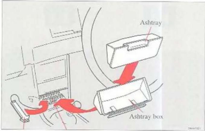
Fuse tool
Fuses
Fuse replacement
If an electrical component fails to function, it is likely that a fuse has blown due to an overloaded circuit. The fuses (and relays) are housed in the central electrical unit behind the dashboard ashtray.
To obtain access to the central electrical unit:
- Remove the ashtray. Pull out and depress the tongue.
- Press up the section marked "electrical fuses – press" and remove the ashtray box.
Behind the ashtray box are 26 fuses in two rows.
Fuse replacement

Numbering of fuses in the fuse box
The fuses must be removed to check if any have blown. Refer to the list of fuses for the fuse number.
Simply pull the fuse straight out. If the metal wire is broken, the fuse is defective. Fit a new fuse with the same ampcrage and colour as the defective one (see top of fuse). Spare fuses are carried at each side (R) of the fuse box: 1 x 15A (blue), 1 x 25A (light yellow), 1 x 30A (green). If fuses burn out repeatedly, have the electrical system tested at a Volvo workshop.
Number
Amperage
| 1 Fuel pump. Electronic engine controls | 25 |
| 2 Central locking. Hazard warning lights. Headlamp flasher | 25 |
| 3 Power front seats, Power supply for trailer | 30 |
| 4 Brake lights, Immobilizer | 15 |
| 5 Glove compartment light, Clock, Radio, Courtesy lighting, Boot light, Power aerial, Door open warning lights, Vanity mirror lighting | 15 |
| 6 Climate unit fan | 30 |
| 7 Foglights | 15 |
| 8 Fasten seat belt light, Direction indicators, Relay for heated front seats, Power window winder relay, Power supply to trailer relay | 15 |
| 9 Power window winders | 30 |
| 10 Heated rear window. Heated door mirrors, Power sunroof | 30 |
| 11 Tank pump, Heated Lambda sensor | 15 |
| 12 Tail lights, Fourth gear lamp (AW71 gearbox), Cruise control, Brake light warning | 15 |
| 13 Hot-start valve, Immobilizer | 15 |
| 14 Power door mirrors, Cigarette lighter, Radio, Tailgate wiper/washer. Outside temperature gauge, Power front seats | 15 |
| 15 Horn, Windscreen/headlamp wash/wipc | 25 |
| 16 Heater fan, climate unit | 30 |
| 17 Left main beam | 15 |
| 18 Right main beam, Foglight relay | 15 |
| 19 Left dipped beam, Beam control | 15 |
| 20 Right dipped beam, Beam control | 15 |
| 21 Left parking light front and rear. Number plate light, Instrument lighting | 15 |
| 22 Seat belt lock light. Right parking lights front and rear, Foglight relay, Instrument lighting | 15 |
| 23 Electrically heated front seats | 25 |
| 24 ABS | 15 |
Fuse replacement
Number
Amperage
25 Automatic dipped ligths (certain markets) for disconnection 25
26 Audio 15
R Spare fuses

The headlamp wipers are protected against overloading by a resistor which disengages the wipers if the blades are blocked by snow or ice. If this happens, turn off the ignition. Once the obstruction is removed, it takes approximately 1 minute until the wipers can be used again.
For more detailed information concerning the function and location of fuses, relays etc., refer to Volvo Service Manuals. These can be ordered from your Volvo dealer.
If you find it difficult to remove a fuse, unclip the fuse tool in the fuse box and use it as described below to remove the fuse.
1 Press the tool on to the fuse.
2 Pull the tool and fuse straight up.
3 Pull out the fuse from the tool and push in a new fuse in the same way.
4 Push in the fuse in the fusebox with the tool.
5 Slide the tool out.
Changing wheels

natural_image
Illustration of a car tire being adjusted for a wheel rim, with a hand adjusting the rim (no text or symbols present)Removing cover - alloy rim
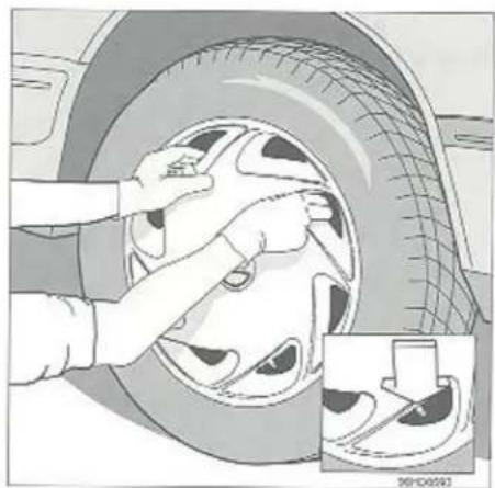
natural_image
Illustration of hands cleaning a car tire with a magnified inset showing the wheel rim detail (no text or symbols)Removing cover - steel rim
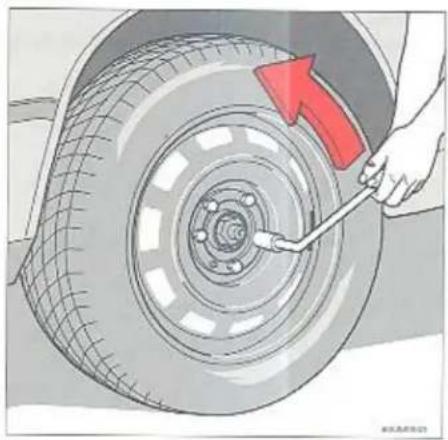
natural_image
Illustration of a car tire being adjusted for a wrench, with a red arrow indicating the direction (no text or symbols present)Unscrew wheel nuts
The spare wheel is located beneath the carpet in the boot.
Removal
- Apply the parking brake and engage first or reverse gear (position P-auto). Place chocks in front of the wheels.
- Cars with steel rims have a removable cover. Remove by placing both hands in the holes on the cover and pulling off. When replacing the cover be sure that the hole is aligned with the valve.
- Unscrew the wheel nuts 1/2–1 turn (anti-clockwise).
Changing wheels

natural_image
Illustration of a person kneeling beside a car with a red arrow indicating the wheel direction (no text or symbols present)Stand next to car
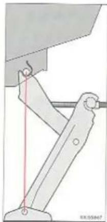
natural_image
Mechanical linkage diagram showing a lever system with a red vertical line and circular end points (no text or symbols)Make sure jack is firmly attached to body
- Place the jack in the jack attachment next to the wheel to be raised:
- Position the jack on the stud in the jack attachment as shown and crank down the foot of the jack until it rests on the ground.
- Check once more to see that the jack is in the attachment as in the diagram and that the foot is vertically underneath the attachment.
- Jack up the car so that the wheel is off the ground.
- Remove the wheel nuts and lift off the wheel. Take care not to damage the threads on the studs.
WARNING!

- Never venture under a vehicle when it is supported by a jack!
• The car and jack must be on a firm, horizontal surface. - Always use the car's original jack when changing wheels.
- Use a pillar or trolley jack and axle stands for all other work on the vehicle.
- Put on the parking brake and put cars with manual transmissions in first gear or reverse, and cars with automatic transmissions in position P.
- Put blocks in front and behind the wheels that remain on the ground.
• Use large wooden blocks or stones.
• The jack screw should always be well greased.
Fitting
- Clean the mating surfaces of the wheel and hub.
- Fit the wheel, noting the position of the small guide stud on the brake disc. Refit the nuts with the tapered ends facing the wheel, (see right hand illustration on previous page).
- Lower the car so that the wheels cannot rotate. Tighten the wheel bolts diagonally a little at a time. Tightening torque approximately 85 Nm (8.5 kpm). It is important to get the correct torque, so check using a torque wrench.
- Refit the hub cap. Some models are equipped with hub caps which cover the whole rim.
- Crank the jack until it folds completely before putting it in its holder in the boot.
Replacing bulbs
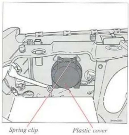

Changing headlamp bulbs
Access to the headlamp bulbs is trom the engine compartment.
Note! Never touch the glass part of the bulb because any contamination from the fingers will give off fumes when the bulb is heated, thus damaging the reflector.
Headlamps
- Switch off the lights and ignition key.
- Open bonnet.
- Release the spring clip retaining the plastic cover and remove the cover.
The spring clip may be difficult to release. - Withdraw the connector; it may be firmly seated.
-
Press and turn the spring-loaded retainer anti-clockwise and remove.
-
Lift out the bulb.
- Insert the new bulb as illustrated without touching the glass. There are three guide lugs on the bulb holder. The lugs are asymmetrically located to ensure proper fit.
• Refit in reverse order to removal
Fog lights
Main beam auxiliary light
- Press clip down and remove plastic cover.
- Release the spring clip outwards and remove bulb.
- Insert the new bulb.
• The bulb holder has two guide lugs to ensure proper fit.
• Refit in reverse order to removal.
Replacing bulbs
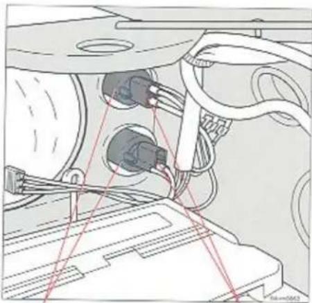
natural_image
Technical diagram of a mechanical assembly with wires and connectors (no visible text or labels)Bulb holder
Connector

Changing bulbs, front
Access to the bulbs is from the engine compartment.
- Switch off the lights and ignition.
- The washer filler tube can be lifted out, on one side, to reach the bulbs.
- Do not remove the connector from the bulb holder. Turn the bulb holder a few mm anti-clockwise and withdraw it.
- Remove the bulb from the holder by pressing and turning a few mm anti-clockwise.
- Insert a new bulb and fit the bulb holder. One of the lugs on the bulb holder is slightly wider than the other two.
Turn the bulb holder clockwise to secure it.
Check that the bulb lights.
Replacing bulbs

Bulb location, left side
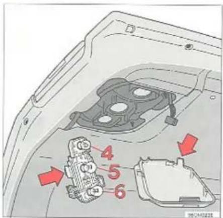
Bulb location, left side
Changing bulbs, tail
Access to the tail light bulbs is from the boot.
Replace one bulb at a time to avoid confusion.
- Switch off the lights and ignition.
• Outer edge: Unscrew screw A and turn down the cover panel. - Hatch: Lift the catch and fold down the cover panel.
- Remove the bulb holder.
- Remove bulb by pressing and turning a few mm anti-clockwise.
- Insert a new bulb and fit the bulb holder in the tail light cluster. One of the plugs on the bulb holder is slightly wider than the other two.
- Turn the bulb holder clockwise to secure it. Check that the bulb lights and refit the cover
Bulbs
| 1+4 Tail light | 5 W | BA 15 s |
| 2 Direction indicator | 21 W | BA 15 s |
| 3 Brake light | 21 W | BA 15 s |
| 5 Reversing light | 21 W | BA 15 s |
| 6 Rear fog lamp (only on right side) | 21 W | BA 15 s |
Replacing bulbs

All tail light bulbs are replaced from inside the vehicle
Replacing tail light bulbs (estate)
Replace one bulb at a time to avoid confusion.
• Turn off the lights.
- Remove the cover with a screw driver.
- Rotate the bulb holder about 1/2" (1 cm) anti-clockwise and remove the holder from the tail light cluster.
- Gently press the bulb into the holder, then rotate the bulb anti-clockwise in order to release it.
| Light | Wattage | Socket |
| 1 Fog light* | 21 W | BA 15 s |
| 2 Reversing lights | 21 W | BA 15 s |
| 3 Turn signals | 21 W | BA 15 s |
| 4 Brake light and tail light | 21/5 W | BAY 15 s |
* Only on right side
- Fit a new bulb in the holder and replace the bulb holder in the tail light cluster.
One of the guide lugs on the bulb holder is slightly wider than the other two and, thus, this lug fits into the widest recess only.
• Turn the bulb holder clockwise
- Check that the bulb lights
• Re-install cluster cover
The guide lugs on the twin-pole bulb are at different heights, and it is only possible to fit these bulbs in one way. Try at first to turn the bulb gently a few millimetres. Do not use force. If this does not work, take out the bulb and turn it half a turn and try again.
Replacing bulbs
Bulb holder

Lens

Insert screwdriver and twist carefully
Side marker lights
Turn off the lights. To remove the bulb, slide the lens forward and withdraw the rear edge. Turn the bulb holder a 1/4 turn and pull out, but do not disconnect the wiring. Withdraw the blown bulb.
Door open warning lamps
All doors are equipped with red warning lamps. To replace a bulb, insert a screw driver as shown in picture and gently turn it to remove the lens. Withdraw the bulb, replace it and re-insert the lens.
Replacing bulbs

Use a screwdriver
Use a screwdriver
Number plate lighting
Switch off the lights and turn the ignition key to position 0. Undo the screws with a screwdriver. Insert the screwdriver as illustrated and turn gently to loosen the glass. Pull the burnt-out bulb straight out. Insert a new bulb and replace the glass.
Number plate lighting
5-door model
Switch off the lights and turn the ignition key to position 0. Undo the screws with the screwdriver in the toolkit. The toolkit contains various driver heads in the screwdriver handle. Remove the glass lens. Remove the bulb and fit a new one. Screw back the glass lens. There is an extra hole in the glass lens which is suitable for a guide pin.
Replacing bulbs
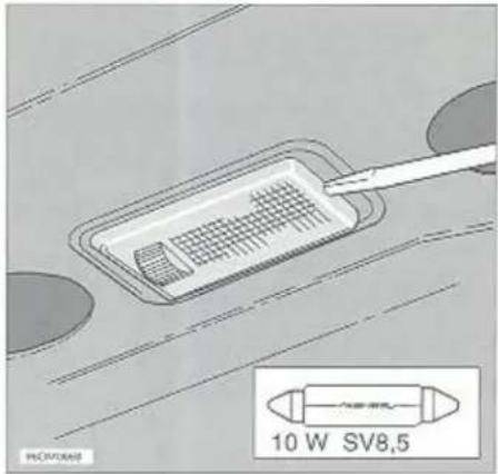
Depress catch with screwdriver

Depress catch with screwdriver
Boot light
To remove bulb depress the catch with a screwdriver, then twist and lift out the housing. Remove the bulb and install a new one.
Cargo space light (estate)
To remove bulb depress the catch with a screwdriver, then twist and lift out the housing. Remove the bulb and install a new one.
Replacing bulbs
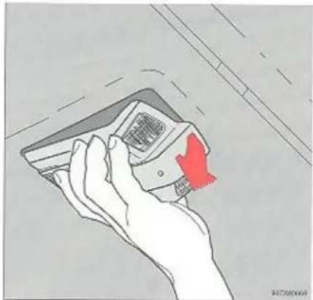
natural_image
Hand holding a small electronic device with a red arrow pointing to it, against a plain background (no text or symbols)Pull down to remove

Reading light
Courtesy light
Courtesy lighting, reading lamps (certain models)
Take hold of the front section of the light as shown and pull straight down.
Replace the blown bulb and check operation before refitting the bulb housing.
Bulb
Courtesy light
Reading lights
Rating
10 W
5 W
Socket
SV8.5
W2.1x9.5d
Replacing bulbs

natural_image
Illustration of a hammer striking a surface with a red arrow indicating force (no text or symbols)Depress catch with a screwdriver

natural_image
Illustration of two hands holding a small 3D object against a striped background (no text or symbols)Depress catches
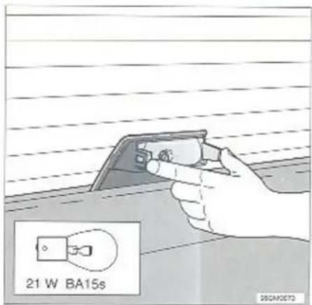
Pull off cover
High-level brake lights
To remove:
Turn off ignition.
Depress catch with a screwdriver (see above).
At the same time, pull the cover towards you.
Depress catches and fit new bulb.
To fit:
Fit the reflector and check that the light works. Press the cover into position, noting the position of the alignment pin at the top.
Estate
To remove:
Turn off ignition.
Take hold of the cover with both hands and pull it towards you.
Depress catches and fit new bulb.
To fit:
Fit the reflector and check that the light works. Align the catches and press the cover into position.
Car care
Car care
Proper car care involves more than just the appearance of your car. The exterior must be protected from the effects of air pollution, rain and mud. The rustproofing under the car should be regularly checked and any damaged areas treated. Damaged paintwork must also be treated immediately to prevent rust formation.
Corrosion protection 6:2
Paintwork damage 6:4
Washing the car 6:6
Cleaning the upholstery 6:8
Corrosion protection
Corrosion protection, inspection and touching-up
Your Volvo was carefully and thoroughly rustproofed at the factory. The underbody and wheel-arches were sprayed with a thick, durable rustproofing compound, and the beams, internal cavities and end sections were sprayed with a low viscous, penetrating rustproofing agent.
Maintain the car's corrosion protection:
- Keep the car clean! Use a high pressure hose to wash chassis components, underbody, wheel wells and the edges of wings – keep the high pressure hose at a distance of at least 30 cm from paintwork!
- The corrosion protection must be inspected by your Volvo dealer. Contact them for more information.
- Should the corrosion protection be damaged by accident or by environmental influence, let your Volvo dealer help you to recover the original corrosion protection to prevent moisture ingress.

natural_image
Line drawing of a car with tire and washer on wheels, no text or symbols presentCorrosion protection
The visible rustproofing
You should check the visible (external) rustproofing at regular intervals. If it is necessary to touch-up the rustproofing, this should be done immediately to prevent moisture ingress. Consult your Volvo dealer.
If you wish to do the work yourself, wash and dry the car and make sure that the surface to be repaired is thoroughly dry and free from all traces of dirt. Use spray-on or brush-on rustproofing compounds. There are two different types of rustproofing compounds:
a) Thin (transparent), for visible sections
b) Thick, for sections on the underbody and wheel-housings which suffer the most wear.
Parts of the car which may need to be touched-up with the recommended rust-proofing compound:
• visible welded seams and panel seams (type a)
• underbody and wheel-housings (type b)
• door hinges (type a)
• bonnet hinges and locks (type b).
After completion of all work on the vehicle, remove excess rustproofing compound with a cloth soaked in white spirit.
Bonnet hinges and locks

Underbody and wheel housings
Paintwork
Paintwork damage requires immediate attention to avoid the formation of rust. It is therefore a good idea to make a habit of regularly checking the paintwork and to touch-up where necessary:
• stone chips and scratches
- flaking e.g. wing edges and sills.
Surfaces should be clean and dry prior to repair. Temperature should be at least 15^ C.

natural_image
Illustration of a hand holding a small object with a label '1' (no text or symbols on the object itself)Remove loose paint flakes with masking tape
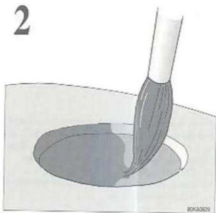
natural_image
Illustration of a brush applying paint to a circular basin (no text or symbols)Brush on primer
Colour code
When ordering touch-up paint from your Volvo dealer, use the colour code number shown on the type designation plate on the right hand wheel-arch in the engine compartment.

Colour code
Minor stone chips and scratches
Material:
- Primer
- Paint - tin or touch-up
- Brush
- Masking tape
- If the stone chip has not penetrated down to the metal and an undamaged layer of paint remains, the touch-up paint can be applied as soon as the spot has been cleaned.
If the stone chip has penetrated down to the metal, proceed as follows:
- Place a strip of masking tape over the damaged surface. Pull the tape off so that any loose flakes of paint adhere to it.
- Stir the primer well and apply to the damaged area with a fine brush or matchstick, fig. 2.
- When the primer has dried, apply a surface coat with a brush. Make sure that the paint has been well stirred and apply it thinly in several layers, allowing it to dry between each application.
Paintwork damage
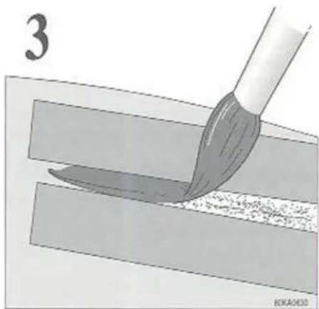
natural_image
Illustration of a paintbrush applying paint to a surface with a tool, no text or symbols presentMask surrounding area
- For scratches proceed as already described but it may be advisable to use masking tape to protect the undamaged paintwork, fig. 3.
- Wait a day or two before applying the finishing coat. Use a soft rag to apply the grinding paste and polish off any blemishes. Apply the paste sparingly.
Washing the car
The car should be washed as frequently as possible, particularly during the winter when road salt and moisture can easily start corrosion. The car can be washed as follows:
- Hose off the dirt underneath the body (wheel-arches, wing edges etc). During high pressure washing the spray mouthpiece must never be closer to the vehicle than 30 cm. Do not spray into locks.
- Hose down the entire car to soften up any dirt etc.
- If the car is exceptionally dirty, first wash it with a cold degreasing agent.
- Wash with a sponge (with or without detergent) using plenty of water. Use preferably tepid but not hot water.
- Hose down with cold water.
• Dry with a clean, soft chamois leather.
● Power radio aerial (optional) must be dried after washing. - Use a nail brush and lukewarm water containing washing-up liquid, to clean wiper blades.
Suitable detergents
Car wash detergent or a dessert spoon of ordinary washing-up liquid diluted with 10 litres of water.
Spots on trim mouldings around windows, wings and doors can be removed with a suitable polish (never use an abrasive cutting paste or steel wool).
Bird droppings
Remove from paintwork as soon as possible. Otherwise the finish will be irreparably damaged.
CAUTION!

When the car is driven away immediately after washing, always gently apply the brakes several times as the car is moving slowly in order to dry off the brakes.
WARNING!

Do not attempt to clean the engine when warm (risk of fire).
When washing the car, remember to remove dirt from all the drain holes.
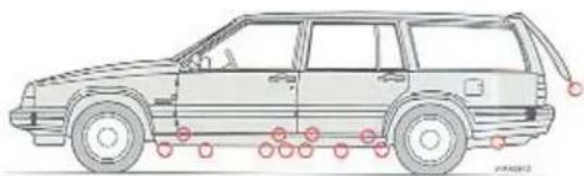
natural_image
Side profile illustration of a car with red circular markers along the side (no text or symbols)Drain holes
Washing
Automatic car washing
An automatic wash is a simple and quick way to clean your car, but it is worth remembering that it can never be as thorough as when you yourself go over the car with sponge and water. Keeping the underbody clean is most important, especially in the wintertime. Not all automatic car washes have facilities for washing the underbody.
Before driving into an automatic wash, make sure that outside rear mirrors, auxiliary lamps, etc., are secure, otherwise there is risk of the machine dislodging them. You should also remove or retract the aerial. Similarly lift the headlamp wiper blades over the lower stop to prevent the machine brushes from damaging the wiper mechanism. (Do not forget to return the wiper arms to their original position.)
Wash the car by hand during the first few months because the paint will not have hardened sufficiently.
An automatic wash can never do as good a job as a manual wash.
Polishing and waxing
The car should be polished and waxed when the surface finish begins to lose its lustre.
Normally it is not necessary to polish the car during the first year after delivery. However, waxing may be beneficial.
Wash and dry the car thoroughly before polishing and/or waxing.
Remove tar spots with white spirit or a tar remover. Larger spots may require a fine rubbing compound.
First polish with the polishing agent and then wax, either with a fluid or solid wax.
Several commercially available products contain both polish and wax. Read the instructions carefully.
A wide range of polymer-based car waxes can be purchased today. The waxes are easy to use and produce a long lasting high gloss finish which protects the bodywork against oxidation, road dirt and fading.
Bumper wraparound
Use normal car wash detergent. Never use petrol or thinners. Use denatured alcohol for difficult spots. To avoid scratches on painted wraparound do not wipe with paper.
Petrol or diesel spills should be cleaned off immediately.
Washing
Cleaning the upholstery
Removal of stains from cloth upholstery
Dirty cloth upholstery can be treated using special detergents which are available through your Volvo dealer. Other chemicals may impair the fire-resistant properties of the upholstery.
It is always best to remove stains immediately, before they have dried. Stains should be dissolved, not rubbed in or scrubbed away with a hard brush.
Removal of stains from vinyl
Never scrape or rub a stain. Never use strong stain removing agents. Wipe with a mild detergent and lukewarm water.
Removal of stains from leather upholstery
Dirty leather upholstery can be treated using special detergents which are available through your Volvo dealer.
We recommend the use of Volvo's leather-care kit once or twice a year to keep the leather supple and comfortable.
Never use strong detergents, petrol, alcohol, white spirit etc., as strong agents such as these may damage cloth, vinyl and leather upholstery.
Removing stains from fabrics and floor mats
Remove stains as soon as possible.
Scrape off the dirt with a blunt knife and remove the surplus with a vacuum cleaner.
Apply a suitable solvent with a clean white cloth. Remove the solvent and dirt with cotton wool.
Bear in mind
- Take extra care when removing stains such as ink, lipstick, since the colouring can spread.
- Use solvents sparingly. Too much solvent can damage the seat padding.
- Start from the outside of the stain and work towards the centre.
Cleaning the seat belts
Use lukewarm water and a mild detergent
Stain removers
Use Volvo fabric cleaning kit or:
Ammonia solution: 1 tsp ammonia (approx. 90%) plus 3 dl water.
Ammonia-soap solution; Mix the above ammonia solution with 1 dl soapy water.
Service – an investment!
An investment which will pay dividends in the form of reliability, durability and also when the time comes to change to a newer car.
Volvo Service 7:2
Engine compartment 7:4
Gearbox oil 7:5
Engine oil 7:6
Power-assisted steering and brake fluid 7:8
Lubrication, body 7:9
Coolant 7:10
Drive belts 7:11
Washer reservoir 7:12
Replacing wipers 7:13
Installation of accessories 7:14
Volvo Service
Pre-delivery service
Your Volvo underwent a thorough quality check and was carefully test run and adjusted before leaving the factory. Prior to being handed over to you, it was subjected to a comprehensive pre-delivery service by your Volvo dealer in order to ensure that it fully meets Volvo standards.
The Volvo Service Programme
In order to benefit continually from the high level of safety and reliability that your Volvo can provide, you should follow the Volvo Service Programme provided in the Service booklet. We strongly recommend that the work listed in these service schedules should be entrusted to your Volvo dealer who has the expertise, technical information and equipment to ensure that the work is done to the high level of quality that you, as a Volvo owner, will accept. You can also rest assured that your Volvo dealer will use only genuine Volvo replacement parts which are of the same high quality as the parts used during the original manufacture of your Volvo.
The Volvo service programme has been designed for Volvo cars being used under average conditions.
If you feel that the uses to which you put your Volvo are not average, consult your Volvo dealer; he will be happy to advise you of any special maintenance that may be required.
Remember
- regular service is necessary to keep your car in good order from both the reliability and the traffic safety aspects
- neglecting a service can result in your car emitting exhaust gases with an unacceptably high level of substances harmful to the environment
- servicing is best done by a Volvo workshop, since it has trained personnel familiar with the products and has specialised tools and reliable service literature from Volvo
- your Service booklet* should be stamped (U.K. only – and the invoices inserted) after each service. A "well-stamped" Service booklet* is an indication that the car has been well cared for and will influence its market value.
Important
If our warranty is to apply we insist on the following conditions:
- that the above-mentioned warranty inspection is carried out at approximately the correct mileage
- that the car maintenance is carried out in accordance with the instructions in this manual
• and that both service inspections and repairs are done by an authorised Volvo workshop.
For more details refer to your Service booklet*.
Service manuals
If you are technically interested and require more detailed information than is available in this booklet we refer you to our Service manuals which are available from your Volvo dealer.
The manuals contain precise information about repairs and adjustments as well as the design and function of the components in your car. They are in fact the same manuals that are used by Volvo personnel.
* U.K. – Service Record book
WARNING!

The car's ignition system operates at very high voltages! The entire ignition system is subject to lethal voltage levels! Do not touch the spark plugs, ignition leads or ignition coils when the engine is running or when the ignition is switched on.
Always turn off the ignition for the following:
- Connection of engine testing equipment.
- Replacement of ignition components such as spark plugs, ignition coils, distributor, ignition leads, etc.
Disconnect the battery for the following:
• Work on the SRS system.
The SRS airbag system's earth connection under the driver's seat should not be disconnected. Do not earth other electrical components under the driver's seat. The SRS airbag system's function may be impaired if it is improperly grounded.
Jacking up the car Workshop jack
When using the workshop jack the four jacking points (two on each side) should be used. These are specially strengthened for lifting. A workshop jack can also be used beneath the final drive casing or between the front wheels beneath the front axle member. Make sure that the jack is securely positioned so that the car cannot slide off. Use chocks or something similar.
The jack supplied with the car should only be used for changing wheels. If a twin post hoist is used to raise the vehicle the front lifting arms should be positioned beneath the control arm strut brackets as illustrated – and not beneath the jacking points. If these instructions are not followed the vehicle may become nose-heavy to such an extent that the rear lifting arms may be unloaded when working on the rear axle or rear suspension. The rear lifting arms must be positioned beneath the rear jacking points.
Note the following before working on your car:
Battery
- Check that the battery leads are correctly connected and properly tightened.
- Never disconnect the battery with the engine running (to replace the battery for instance).
- Never use a booster charger to charge the battery. The battery leads should be disconnected when charging the battery.
- Switch off the radio before disconnecting the battery leads. If your radio has an anti-theft code and the battery is disconnected, the radio code has to be re-entered for the radio to function.
Environmental care
The battery contains acid which is corrosive and toxic. It is thus vital that the battery is disposed of in an environment-friendly manner. Ask your Volvo dealer for assistance.

Engine compartment
Engine Compartment
1 Windscreen washer reservoir
2 Air filter
3 Expansion tank, coolant system
4 Oil filler cap, engine
5 Dipstick, engine
6 Brake fluid reservoir
7 Dipstick, automatic transmission
8 Oil reservoir, power steering
9 Battery
10 Engine type designation
11 Data plate
12 Power steering and water pump belts
13 Alternator belt
14 Air conditioning belt
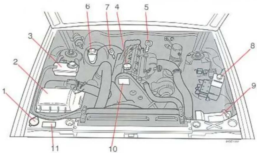

WARNING!
Thermo-electric cooling fan:
The fan can start working again after the engine has been switched off!

Automatic transmission

Dipstick handle is yellow
A cold gearbox oil – oil temperature 40°C. This is a normal temperature for the transmission after idling for about 10 minutes. At oil temperatures below 40°C, the level may be below the MIN mark. B warm gearbox oil – oil temperature 90°C. This temperature is reached when driving for about 30 minutes. At oil temperatures above 90°C, the level may be above the MAX mark.
The engine should be idling when checking the transmission oil level.
Check the oil level as follows:
Park the car on level surface with the engine idling.
Slowly move the selector lever through all the gear positions and then to position P.
Wait 2 minutes before checking the oil level. As the illustration shows, the dipstick has a "Cold" and a "Warm" side.
The oil level should be between the MIN and MAX marks.
Wipe the dipstick with a clean cloth.
CAUTION! The oil may be very hot
The transmission is topped up via the dipstick tube.
For location - see 7:4.
The space between the MIN and MAX marks on the dipstick corresponds to 0.5 litre. Do not fill the transmission with too much oil, since this can result in oil being ejected from the transmission.
Too little oil, on the other hand, can negatively affect transmission operation, particularly in very cold weather.
Oil-level check: Every service.
Quality: Dexron II D or Dexron II E at all temperatures.
Engine oil, checking, changing
Check engine oil regularly when filling up
It is particularly important to check the engine oil during the running-in period. Park the car on a level surface and wait at least 1 minute after the engine has been switched off so that the oil can run back into the sump. To obtain a reliable reading, check the oil level with the engine cold. Wipe the dipstick before checking.
The level should lie within the hatched section on the dipstick.
The difference between the MAX and MIN marks on the dipstick represents approximately 1 litre.
If the level is on MIN, top up as follows:
Engine cold - 1 litre
Engine warm - 0.5 litre

Draining the oil
Drain the oil while it is still hot.
WARNING!

The oil may be very hot.
Prolonged and repeated contact may cause serious skin disorders, including dermatitis and cancer. Avoid contact with skin as far as possible, wash thoroughly after any contact. Keep out of reach of children.
To add or change engine oil
Add oil of the same kind as already used.
After an oil change, the oil level will lie between the two marks on the dipstick i.e. the MAX and MIN. This is quite normal. Do not add too much oil otherwise excessive oil consumption will result.
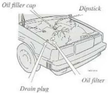
Changing oil filter
Follow the instructions on the cartridge.
It is illegal to pollute drains, water courses and soil. Use authorised waste collection facilities, including civic amenity sites and garages providing facilities for disposal of used oil and used oil filters. If in doubt, contact your local authority for advice on disposal.
WARNING!
Do not spill oil on hot exhaust pipe (risk of fire).

Oil quality:
CCMC G5
Synthetic or semisynthetic oils may be used if their specifications comply with the above.
Oil additives should not be used unless recommended by an authorised Volvo workshop.
Viscosity: (stable ambient temperatures)

bar
| Category | Value | |---|---| | -30 | 40 °C | | -22 | 104 °F | | -20 | 86 | | -10 | 30 | | 0 | 20 | | 10 | 10 | | 20 | 50 | | 30 | 32 | | 40 | 14 | | 5W/30 | 68 | | SAE 5W/40 | 86 | | SAE 10W/30 | 32 | | SAE 10W/40 | 32 | | SAE 15W/40 | 68 | | SAE 20W/40 | 32 | | SAE 30 | 14 | | SAE 40 | 14 |SAE 15W/40 or SAE 20W/40 oils are recommended for use in extreme driving conditions that involve excessive oil consumption and high oil temperatures, e.g. mountain driving with frequent decelerations or fast motorway driving. Note however the lower temperature limits.
Capacity:
3.85 litres (add 0.6 litres if oil cooler is drained).
Oil and filter change
| Driving conditions | Change interval oil + filter |
| Unfavourable | Every 7500 km or6 months, whichever occurs first. |
| Average | Every 15000 km or12 months, whichever occurs first. |
Unfavourable conditions
• long distance driving in dusty/sandy areas
• long distance towing
• long distance driving in hilly terrain
- stop-start driving
- low temperatures (below zero), driving short distances (less than 10 km)
• sustained high speed driving
Brake fluid, Power-assisted steering fluid

Brake fluid
Fluid level should be above the MIN mark.
Fluid type: Brake fluid DOT 4+
Fluid level check: Regularly
Fluid change: Every second year
Capacity: 0.4 litres
Brake fluid should be changed every year if the brakes are used frequently and severely e.g. driving in mountainous areas or in tropical regions with high humidity.
Brake fluid change is not included in any service but can be carried out in conjunction with a service at an authorised Volvo workshop.
For location - see 7:4
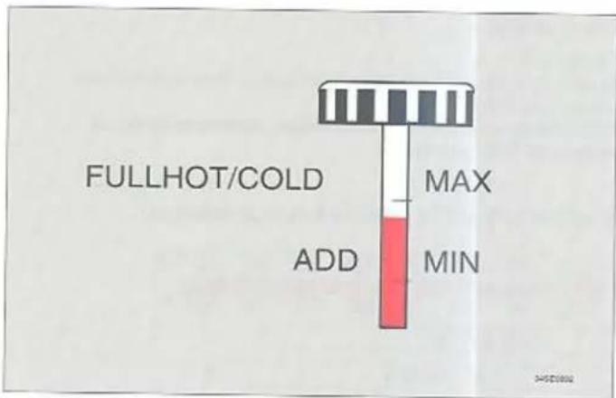
Power-assisted steering fluid
The dipstick is attached to the cap.
Fluid level should be above the MIN mark.
Fluid quality: ATF
Fluid capacity: 0.5 litres (0.9 pints)
Fluid level check: Every service
Fluid change: No change needed
For location - see 7:4
Lubricating points, bodywork


3 Door stop (located at lower hinge)
No. Lubricating point
1 Bonnet lock (3)
2 Bonnet hinge (2)
3 Door stop (4)
Door hinge (8)
4 Sun roof wind deflector (1)
5 Door lock catch plate (4)
6 Boot lock (1)
Lubricant
Oil
Oil
Oil
Oil
Low temperature grease Low temperature grease or Volvo lock lubricant
No. Lubricating point
7 Window winder (4)
Lock device (4)
(on inside of door)
8 Front seat slide rail (4) and latch (2)
9 Door locks
Lubricant
Oil, grease
Low temperature grease
Oil
Low temperature grease or Volvo lock lubricant
Cooling system
Coolant composition
Do not top up the cooling system with water only. Use a mixture of 50% Volvo anti-freeze and 50% water all year round.
NOTE! Some engine components are made of an aluminium alloy. It is therefore very important to use Volvo coolant as it contains a special anti-corrosion agent!
Different types of coolant should not be mixed together!
The car is delivered from the factory with the radiator filled with coolant that provides protection against frost down to -35^ C.
Cooling system capacity: 8.5 litres
Check the coolant regularly; it does not normally need to be replaced
The level should be between the MAX and MIN marks on the expansion tank.
The cooling system is under pressure when hot. If it is necessary to add coolant unscrew the cap slowly to release the pressure.
Note!
The cooling system must always be kept filled to the correct level. If it is not kept filled, there can be high local temperatures in the engine which could result in damage.
Environmental care
If you change the coolant yourself, you should ensure that the used coolant is disposed of in an environmentally safe manner. Your Volvo dealer can assist you in this matter.
Changing the coolant
If you live in a hot climate let your Volvo workshop clean the cooling system at the same time as the coolant is replaced.
To drain
1 Move the heater controls to MAX heat.
2 Remove the expansion tank cap (slowly if engine is hot).
3 Open the drain tap.
4 Disconnect the hose from the bottom of the radiator.
To fill
1 Close the drain tap.
Reconnect the hose and add coolant to the expansion tank until it is completely full i.e. above MAX.
2 Fill the expansion tank to MAX or slightly above.
3 Warm-up the engine for 5 minutes, topping-up with coolant as required. Check for leaks.
4 Screw on the expansion tank cap.


Battery
Driving conditions, the way you drive, the number of starts, climate conditions, etc., can have an effect on the life and function of the battery. You should bear in mind the following points to ensure that the battery works satisfactorily:
- Check on a regular basis (at least every six months or 15,000 km) that the fluid level in the battery is correct (see illustration).
- Check all the cells in the battery. Use a screw driver to remove the cover. A torch is useful when checking fluid levels. Each
cell has its own level indicator (see illustration).
- If necessary, top up the battery with water to the maximum level. Minimum level is 10 mm over the lead plates (see illustration).
- If you recharge your battery, you must check the fluid level after recharging and, if necessary, top up with water.
- Do not use ordinary tap water. Use distilled or dcionised water.
• Make sure that the plugs are properly tightened. - Batteries with grey plugs (vent filters) - the grey plug must not be replaced with a black airtight plug.
WARNING!

Remember that the battery contains oxyhydrogen which is extremely explosive. Naked flames or smoking in the vicinity of the battery can cause the battery to explode resulting in damage to you yourself and the car.
The battery also contains sulphuric acid which can cause serious corrosion. If the acid comes into contact with your eyes, skin or clothes, rinse with plenty of water. If the acid splashes in your eyes, first rinse and then seek medical attention immediately.
Battery, Fan belts and drive belts
Replacing fan belts
If you replace any belts it should be possible to depress the belt 1–3 mm. After replacement, belt tension should also be checked/adjusted by an authorised Volvo workshop.
Belt check
Check the belts regularly to make sure they are in good condition and are clean. Worn or dirty belts can cause poor cooling and alternator output as well as impair the operation of the power-assisted steering and the air conditioning unit.
Drive belts should be checked and adjusted by a Volvo dealer
Due to limited accessibility you may have difficulty adjusting/replacing the belts. They should therefore be serviced by a Volvo dealer.
Washer nozzles, Washer reservoir

natural_image
Diagram of a car's frontview with steering wheel and attached sensor device (no text or symbols)Use a screwdriver to adjust
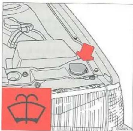
natural_image
Technical line drawing of a car engine compartment with a red component and a red emblem (no text or symbols)Washer reservoir
Adjusting the washer nozzles
The washer spray should strike the windscreen as illustrated.
Use a small screwdriver to adjust the nozzle.
Washer reservoir
The windscreen and headlamp washers (and tailgate washer on estate cars) are fed from the same fluid reservoir located in the engine compartment, holding approx. 4 litres (7 pints). In cold weather fill the container with a washer solvent containing de-icer.
Wiper blades

natural_image
Illustration of hands using a tool to cut or draw a metal object, with a red ribbon visible (no text or symbols)Replacing windscreen and tailgate wiper blades
Lift off the wiper arm from the windscreen and hold the blade at right angles to the arm. Then crimp the ends of the plastic clip at the back of the arm.

natural_image
Illustration of a hand using a tool to adjust or install a mechanical component (no text or symbols visible)Slide the wiper blade along the arm to release it from the hook.

natural_image
Illustration of hands using a tool to cut or adjust a mechanical component (no text or symbols visible)Fit new blade in reverse order to removing and make sure that it is properly attached to the wiper arm.
Use a nailbrush and luke warm water containing a few drops of washing-up liquid to clean wiper blades. If the blades still leave marks on the wind-screen, fit new ones.
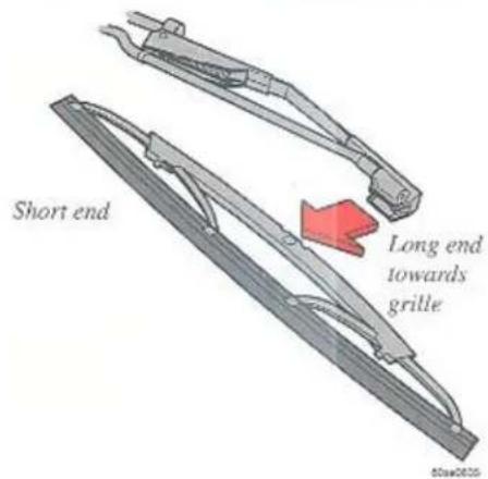
Replacing headlamp wiper blades \*
Pull out the wiper arm from its pivot point. Withdraw the wiper blade. The blade can now be clicked into place. The long end points towards the radiator grille.
* Certain markets
Installation of accessories
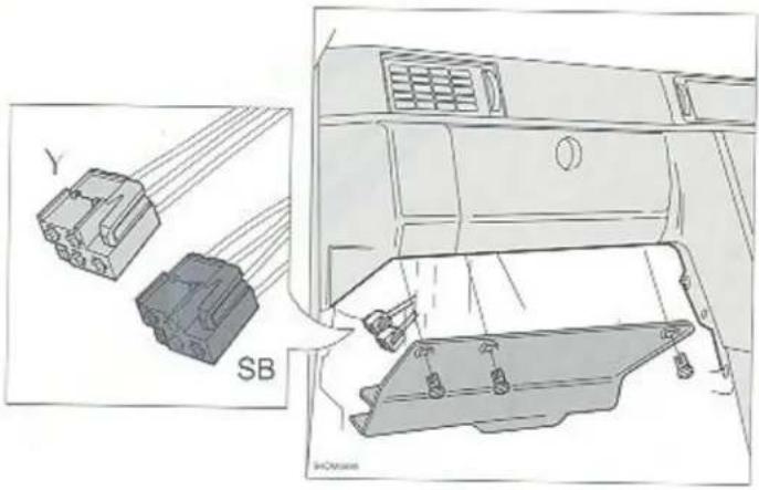
Installation of telephone and accessories
In order to avoid interference and damage to your car's electrical system, your car is supplied with two connectors for the installation of a telephone and other electrical accessories. The two connectors are located beneath the glove compartment behind the soundproofing panel. When installing the accessories or the telephone, contact an authorised Volvo workshop.
When installing Volvo genuine accessories/telephone, the enclosed installation instructions should be followed.
Black connector (for accessories)
| Position | Connection | Max. load |
| 1 | Earth (31) | 4 A |
| 2 | Parking lights (58) | 1 A |
| 3 | Rheostat (NR) | 1 A |
| 4 | Battery + (30) | 3 A |
Yellow connector (for telephone)
| Position | Connection | Max. load |
| 1 | Earth (31) | 4 A |
| 2 | Ignition positions I and II | 1 A |
| 3 | ||
| 4 | Battery + (30) | 3 A |
Specifications
Specifications
This chapter contains data which you may find useful.
Type designations 8:2
Dimensions and weights 8:3
Lubricants, Cooling system, Fuel 8:4
Power transmission 8:5
Front end 8:5
Electrical system 8:6
Engine 8:7
Specifications
Type designations
In all correspondence concerning your vehicle and when ordering parts, the type designation, chassis and engine numbers should always be quoted.
1 Type and model year designation, chassis number
Stamped on the right middle door pillar.
On certain markets also located on top left surface of dashboard.
2 Type designation, max permissible loads and code number for colour and upholstery
On a plate above right headlamp. Australia: Also includes date of manufacture.
3 Type designation, serial number and part number of engine. On left side of engine.
4 Type designation, serial number and part number of transmission. Manual gearbox: underneath the gearbox. Automatic transmission: on left side of transmission.
5 Final drive reduction ratio, part number and serial number
On a plate on left-hand side of rear axle.
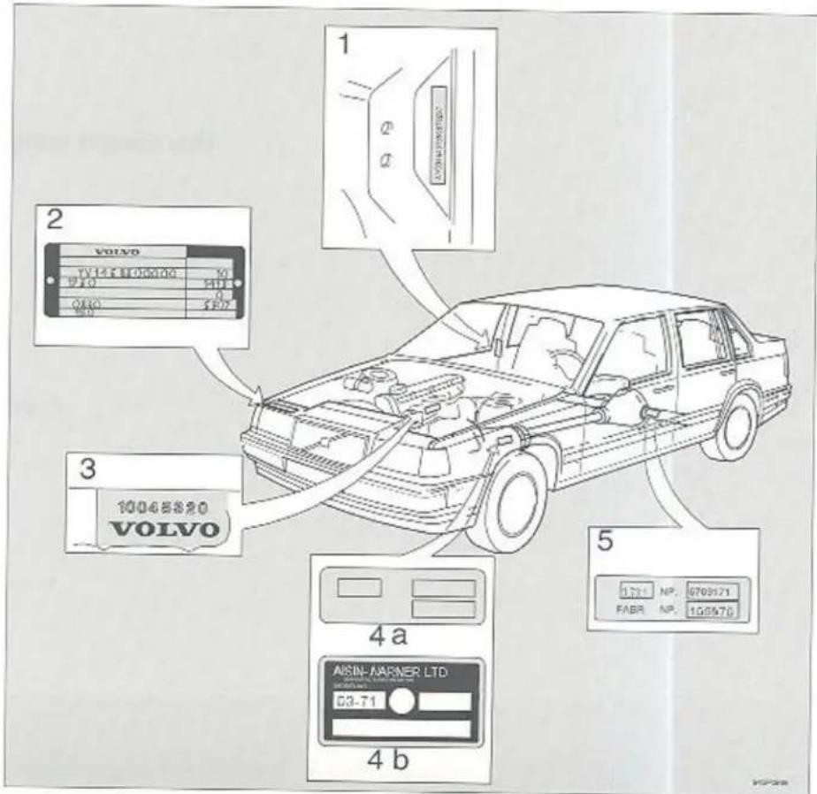
Specifications
Dimensions and weights
Length 487 cm
estate 484 cm
Width 175 cm
Height 141 cm
cstate 143 cm
Wheelbase 277 cm
Track. front 147 cm
rear 146 cm
Turning circle 9.9 m
Data plate with max. permissible loads. On a plate above right head-lamp.
Permitted gross vehicle weight
Max* axle load, front
Max* axle load, rear

* The load must be distributed so that the recommended maximum laden weight or axle load is not exceeded.
Kerb weight varies between 1300 and 1500 kg for different models and markets. Vehicles should be individually assessed
Permitted load = gross vehicle weight - kerb weight
Max. roof load 100 kg
Max. trailer (caravan) weight 1800 kg
Cargo space, Estate
Length, seat up 106 cm
seat down 194 cm
Tailgate opening, max. width 146 cm
max. height 77 cm
Capacities in litres
Fuel tank 75 litres
Cooling system 8.5 litres
Engine oil 3.85 litres
add extra 0.6 litre if oil cooler is drained
Gearbox oil
automatic 7.5 litres
M-90 1.75 litres
Rear axle oil 1.6–1.75 litres
Power steering 0.5 litre
Washer reservoir 4.0 litres
Brake system 0.4 litre
Air conditioning....950 grammes*
"See next page!
Oils
| Lubricants | ||
| Engine: | Cooling system: | |
| Oil quality: CCMC G5 | Type | Pressurized |
| Viscosity: See 7:7. | Capacity | c. 8.5 litres |
| Volume: 3.85 litres. | Thermostat starts opening | 87C° |
| Synthetic or semi-synthetic oils may be used if their specifications comply with the above. | Fuel (DERV): | BS 2869 Class A2 DIN 51 601 |
| Oil additives should not be used unless recommended by an authorised Volvo workshop. | Petrol: (min. octane) | All F engines (cars with catalysers): recommended 95 (4 Star) unleaded min 91 (2 Star) unleaded All G engines: min 91 (4 Star) leaded/unleaded |
| Gear Box - automatic: | ||
| Oil quiality: ATF-oil type Dexron II D or Dexron II E | ||
| Volume: 7.5 litres | ||
| Gearbox - M-90: | ||
| Oil quality: Volvo synthetic gearbox oil 97308 | ||
| Volume: 1.75 litres | Air Conditioning: | |
| Rear axle: | Refrigerant: | R 134a (frecon-free coolant) |
| Oil quality: Volvo rear axle oil, API-GI.-5 (MIL-L-2105 C or D). | Volume: | 950 grammes |
| Viscosity: SAE 80 or 80 W/90 | Oil type: | Sciko-Seiki SS-121DS5 P/N=1161426-0 |
| Capacity: 1.6 l-1.75 litre | ||
| Power steering: | ||
| Oil Quality: ATF | ||
| Capacity: 0.5 litre | ||
| Brake fluid: | ||
| Type: Brake fluid to DOT 4+ | ||
| Capacity: 0.6 litre | ||
Specifications
| Power transmission | Recommended min. and max. speeds mph (km/h) | ||||||
| Single, dry disc clutch, Manual, fully synchronized, 5-speed gearbox. Alternatively, fully automatic 4-speed gearbox comprising a hydraulic converter and planetary gear. Hypoid type final drive. | Engine | 1st | 2nd | 3rd | 4th | 5th | |
| 0-30(0-45) | 10-50(20-80) | 20-80(30-125) | 25<(40<) | 45<(70<) | |||
| Gearbox | |||||||
| Manual | Front end | ||||||
| Type designation | M 90 | McPherson type spring-strut suspension. Shock absorbers housed in strut casing. Rack and pinion steering. | |||||
| Reduction ratio | Safe-type steering column. | ||||||
| 1st gear | 3.91:1 | The alignment specifications apply to an unladen car but include fuel, coolant and spare wheel. | |||||
| 2nd gear | 2.20:1 | ||||||
| 3rd gear | 1.38:1 | ||||||
| 4th gear | 1.00:1 | Toe-in, measured on the rim measured tyrc sides | 2.3 ± 1.0 mm2.8 ± 1.3 mm | ||||
| 5th gear | 0.81:1 | ||||||
| Reverse | 3.00:1 | ||||||
| Automatic | |||||||
| Type designation | AW 70/71 | ||||||
| Reduction ratio | |||||||
| 1st speed | 2.45:1 | Rear axle ratio | |||||
| 2nd | 1.45:1 | Gearbox | AW | ||||
| 3rd | 1.00:1 | Ratio | 3.73:1 | ||||
| 4th | 0.69:1 | Gearbox | M 90 | ||||
| Reverse | 2.21:1 | Ratio | 3.31:1 (4 door - model)3:54:1 (5 door - model) | ||||
Specifications
Electrical system
12-volt system with voltage-regulated alternator. Single-pole system where chassis and engine frame are used as conductors.
Negative pole connected to chassis.
| Voltage | 12 volt |
| Battery,capacity | 420 A, 75 min |
| 520 A, 90 min | |
| specific gravity,electrolyte | 1.28 |
| recharge at | 1.23 |
| Alternator | 100 A |
| 80 A | |
| 65 A | |
| Starter motor | 1.4 kW |
Bulbs 12 V
| 1 | 2 | 3 | 4 | 5 |
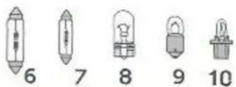
965790768
| Bulbs | Rating | Socket | Fig. no. |
| Headlamp | 60/55 W | H4 | 1 |
| Spotlamp or foglamp | 55 W | H3 | 2 |
| Parking/front | 5 W | BA 15s | 5 |
| Direction indicator, front | 21 W | BA 15 s | 4 |
| rear | 21 W | BA 15 s | 4 |
| side | 5 W | W 2.1x9.5 d | 8 |
| Tail light | 5 W | BA 15 s | 5 |
| High level brake lights | 21 W | BA 15 s | 4 |
| Brake light (scdan) | 21 W | BA 15 s | 4 |
| Tail/Brake light (estate) | 5/21 W | BAY 15d | 3 |
| Reversing light | 21 W | BA 15 s | 4 |
| Rear foglamp | 21 W | BA 15 s | 4 |
| Number plate light (sedan) | 5 W | W 2.1 x9.5 d | 8 |
| Number plate light (estate) | 4 W | BA 9 s | 4 |
| Door warning lamp | 3 W | W 2.1x9.5 d | 8 |
| Courtesy light | 10 W | 5 W | 6 |
| Vanity mirror light | 3 W | SV 7 | 7 |
| Reading light, front | 5 W | W 2.1 x9.5 d | 8 |
| Engine compartment light | 10 W | SV 8.5 | 6 |
| Boot light | 10 W | SV 8.5 | 6 |
| Glove compartment light | 2 W | BA 9 s | 9 |
| Instrument lighting | 3 W | W 2.1x9.5 d | 8 |
| Lighting, control panel | 1.2 W | W 2x4.6 d | 10 |
| selector panel (auto) | 1.2 W | W 2x4.6 d | 10 |
| Warning/Indicator lamps | 1.2 W | W 2x4.6 d | 10 |
Specifications
| Engine | B230FK | B230GK | B200FT | B200GT | B230FT |
| Output [kW/rps] | 99/82 | 99/82 | 114/93 | 114/93 | 121/80 |
| [hp/rpm] | 135/4900 | 135/4900 | 155/5600 | 155/5600 | 165/4800 |
| Torque [Nm/rps] | 230/38 | 230/38 | 230/60 | 230/60 | 264/57 |
| [kpm/rpm] | 23.4/2300 | 23.4/2300 | 23.4/3600 | 23.4/3600 | 27.0/3450 |
| No. of cylinders | 4 | 4 | 4 | 4 | 4 |
| Bore [mm] | 96 | 96 | 88.9 | 88.9 | 96 |
| Stroke [mm] | 80 | 80 | 80 | 80 | 80 |
| Cubic capacity [dm3 (l)] | 2.32 | 2.32 | 1.99 | 1.99 | 2.32 |
| Compression ratio | 8.7:1 | 8.7:1 | 8.5:1 | 8.5:1 | 8.7:1 |
| Valve clearance | |||||
| warm engine [mm] | 0.40-0.45 | 0.40-0.45 | 0.40-0.45 | 0.40-0.45 | 0.40-0.45 |
| cold engine [mm] | 0.35-0.40 | 0.35-0.40 | 0.35-0.40 | 0.35-0.40 | 0.35-0.40 |
| Firing sequence | 1-3-4-2 | 1-3-4-2 | 1-3-4-2 | 1-3-4-2 | 1-3-4-2 |
| Ignition setting [°btdc/rps] | 12/13 | 12/13 | 12/12-13 | 12/12-13 | 12/13 |
| Spark plugs | P/N 270746-1 | PNN 270746-1 | P/N270747-9 | P/N270747-9 | P/N 270746-1 |
| Bosch WR7DC* | Bosch WR7DC* | Bosch WR6DC* | Bosch WR6DC* | Bosch WR7DC* | |
| electrode gap [mm] | 0.7-0.8 | 0.7-0.8 | 0.7 | 0.7 | 0.7 |
| tightening torque [Nm] | 20-30 | 20-30 | 25 | 25 | 25 |
| Octane rating | |||||
| recommended | 95** | 95** | 95** | ||
| minimum | 91** | 91*** | 91** | 91*** | 91** |
* or equivalent
** unleaded
^* 班米尔 leaded/unleaded
Unleaded fuel
Cars equipped with a catalytic converter must always be run on unleaded fuel in order to avoid damage to the converter. Today all Volvo petrol engines can be run on unleaded fuel on the condition that the octane requirement is fulfilled.
Fuel consumption
Fuel consumption
| Model | Engine | Transmission | Urban (cold) | Extra Urban | Combined | CO2 g/km | |||
| mpg | L/100 | mpg | L/100 | mpg | L/100 | ||||
| 940 4d | B230FK | Automatic | 19.1 | 14.8 | 31.7 | 8.9 | 25.7 | 11.0 | 264 |
| 940 4d | B230FK | Manual | 20.6 | 13.7 | 34.0 | 8.3 | 25 | 10.3 | 244 |
| 940 5d | B230FK | Automatic | 19.1 | 14.8 | 31.7 | 8.9 | 25.7 | 11.0 | 264 |
| 940 5d | B230FK | Manual | 20.6 | 13.7 | 34.0 | 8.3 | 25 | 10.3 | 244 |
| 940 5d | B230FT | Automatic | 18.8 | 15.0 | 31.0 | 9.1 | 25 | 11.3 | 264 |
| 940 5d | B230FT | Manual | 20.0 | 14.1 | 33.6 | 8.4 | 26.9 | 10.5 | 248 |
The fuel consumption figures shown are obtained from cars tested against strict procedures in laboratory conditions. These test procedures allow consumers to make accurate comparisons between makes and models. However, since it is not possible to reproduce the test conditions during normal motoring, comparison between these results and every day driving is not valid. Should you have any cause for concern your Volvo Dealer has the expertise and equipment to ensure that your car is operating normally.
Exhaust emission control
Emission control
The Volvo Car Corporation has a long tradition of involvement in environmental considerations. As early as 1970, we began work on the development of cleaner engines and this effort resulted in the three-way catalytic converter which is regulated by a Lambda Sond oxygen sensor.
Volvo was the first manufacturer of passenger cars to engage in full scale supplies of cars with this system to the USA, way back in 1976. It is also important that you as a car owner understand which of the car's components can affect the contents of its exhaust gases, and which measures are necessary to limit the emission of harmful exhaust gases.
Please refer to the section entitled "Emission Regulation Service".
Environmental care
Volvo has a long tradition of environmental care and awareness. Brakes without asbestos, engines with catalytic converters and methanol power are examples of the Volvo Car Corporation's tireless efforts to minimise the impact of motoring on the environment.
Our specific services too have significance for the environment, for instance the use of Genuine Volvo parts and the maintenance of ignition and fuel systems and other measures which have a direct effect in terms of reduced exhaust emissions. We would also like to emphasise the environmentally safe way in which authorised Volvo workshops dispose of ecologically dangerous products such as used lubricants, used coolants etc.
Catalytic converter 9:2
Positive crankcase ventilation, Fuel evaporation system 9:3
Emission regulation service 9:4
Emission controls

Lambda-sond
Catalytic converter
This is a supplementary device in the exhaust system, designed to clean exhaust gases. It consists mainly of a container with a ceramic insert, designed to let the exhaust gases pass through channels in the insert. The channel walls are coated with a thin layer of platinum-rhodium. These metals act as catalysts - causing a chemical reaction without being consumed by it.
CAUTION!
Vehicles with a catalytic converter must use unleaded fuel only. Otherwise the catalytic converter will become ineffective. See "Fuel requirements".
Lambda-sond (oxygen sensor) system
This is an emission control system designed to reduce emissions and improve fuel economy. An oxygen sensor monitors the composition of the exhaust gases leaving the engine. The exhaust gas analysis is fed into an electronic unit which continually influences the injectors. This adjusts the air-fuel ratio to provide optimum conditions for combustion and efficient reduction of the three major pollutants (hydrocarbons, carbon monoxide and nitrous gases) by a 3-way catalytic converter.
Exhaust gas regulation

flowchart
graph TD
    A["入口"] --> B["出口"]
    B --> C["中端口"]
    C --> D["出口"]
    D --> E["中端口"]
    E --> F["出口"]
    F --> G["出口"]
    G --> H["出口"]
    H --> I["出口"]
    I --> J["出口"]
    J --> K["出口"]
    K --> L["出口"]
    L --> M["出口"]
    M --> N["出口"]
    N --> O["出口"]
    O --> P["出口"]
    P --> Q["出口"]
    Q --> R["出口"]
    R --> S["出口"]
    S --> T["出口"]
    T --> U["出口"]
    U --> V["出口"]
    V --> W["出口"]
    W --> X["出口"]
    X --> Y["出口"]
    Y --> Z["出口"]
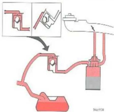
Positive crankcase ventilation
Crankcase ventilation prevents the emission of crankcase gas into the surrounding air. Instead, these gases are sucked in via the inlet manifold down into the cylinders where they aid in the combustion process.
Crankcase ventilation, inspection
The condition of the rubber hoses and their degree of blockage should be checked according to the Volvo Service Programme. The rubber hoses should be replaced if they are in poor condition. The calibrated nipple should be removed and cleaned. The flame barrier should be replaced.
Fuel evaporation system
Cars equipped with catalytic converters feature a fuel evaporation system which prevents the emission of fuel vapour into the surrounding air.
The system consists of an equalizing reservoir in the fuel tank, a "Roll-Over" valve on the cross-member ahead of the fuel tank and a carbon filter with integrated vacuum valve in the engine compartment beside the air filter.
The various components are interconnected by hoses which lead the gases from the fuel tank to the filter. These gases are stored there until the engine is started, when they are sucked into the engine's inlet manifold during acceleration (not at idle speed).
Emission regulation service
Low exhaust emission requires ...
... as regards service:
- That the car receives the service specified in the warranty as well as regular service according to Volvo's service programme. The implications of these concepts are dealt with in greater detail on page 7:2 and in the Warranty & Service Manual. We recommend that you schedule your car for service just prior to the annual road-worthiness test.
... as regards engine components:
• That the valves are properly adjusted,
- That the engine receives proper lubrication. Page 7:6 describes the replacement of engine oil and the oil filter.
- That the cooling system functions satisfactorily. The replacement of coolant, the coolant's anti-freeze properties etc. are described on page 7:10. Drive belts, checking of belt tension etc. are described on page 7:11.
- That the exhaust system is totally free from leakage and is sound.
... as regards the fuel system:
• That the pipes and connections are sound and free from leakage
• That the fuel and air filters are not blocked.
- That the fuel injection system is so adjusted that the carbon monoxide content of the exhaust gases lies within permitted levels.
• That the car is run on the appropriate fuel.
- That cars with catalytic converters are driven on unleaded petrol.
... as regards the ignition system:
- That the spark plugs are undamaged and have the appropriate electrode gap.
Audio
Audio
The following pages describe the use of the CR-906 cassette radio with CD control.
Anti-theft code 10:4
Radio 10:5
Cassette deck 10:12
CD 10:14
General information 10:17
Technical specifications 10:20
RDS functions
Radio Data System\*
The Volvo CR-906 is designed for the digital information system RDS (Radio Data System), developed by Swedish Telecom together with the European Broadcasting Union (EBU). RDS features automatic programming and instant traffic information and it widens the possibilities for programme choices. The transmitter broadcasts information about the programme. This information is represented by a data code, which identifies the programme, irrespective of on which frequency the information is transmitted.
This means that the driver does not have to change the frequency if he wants to continue listening to the same programme. Every station/programme has a specific identification which the radio searches for. The radio is then automatically retuned while driving.
The RDS radio can also receive traffic information. This is transmitted with a special signal which cuts through any normal radio transmission, tape or CD transmission and is always heard at normal volume.
Some countries transmit "PTY" (Programme Type) and "EON" (Enhanced Other Network) information, which are an extension of the RDS system.
EON is a function within the RDS system, whereby a number of stations (with or without traffic information) are linked together in a network. This means that if you are tuned to an EON-linked station without traffic information, you will nevertheless receive such information from another station in the EON-network, when transmitted.
There are a number of other features in the RDS-system, such as time control signals, alarms etc. This system is being constantly developed and covers most of Western Europe.
Your Car-Radio complies with the requirements of the EC Directive 89/336/EEC. The requirements regarding susceptibility according to EN55020 and regarding interference according to EN 55013 are observed in case of operation in residential areas, on business premises and in small scale enterprises, inside as well as outside of the buildings.
The following pages describe the function and operation of Volvo Cassette Radio CR-906

- ON/OFF
Volume
• Balance left-right (push)
- Fader front-rear (pull)
-
Anti-Theft indicator
-
Bass control
- Treble control
-
Waveband selector
-
Up and Down tuning
- CD
- Display
- Preset buttons
-
Autostore function
-
Programme type
- Traffic Programme
- Tape direction
- Cassette slot
- Cassette eject
Anti-theft code

Code Card

(01A)0667
Code cards
Each set is supplied with two cards marked with the correct code of the set. Do not keep these cards in the vehicle.
Anti-theft code
The radio features anti-theft circuitry. If the set is removed from the vehicle or if the battery power is disconnected, a special code must be entered to enable operation of the set. Your dealer will provide you with the correct code when delivering the car.
When the engine is switched off and the ignition key is removed the anti-theft indicator flashes.
Using the code
- Make sure the radio is properly connected.
- Turn on the set. "CODE" is displayed.
- Enter the four-digit code with the preset buttons 1 to 6.
- If an incorrect code has been entered, "CODE" is displayed again. Repeat point 3 again.
NOTE: The set allows three coding attempts. Then it locks and remains locked for 2 hours. The unit must be connected during this time. Enter the code again once this period has elapsed.
Radio

A - On/Off switch and volume control
Turn the knob clockwise to switch on and anti-clockwise to switch off. This knob also regulates volume.
B - Waveband selector
Press button WB for the waveband required. The set waveband is then displayed; U1, U2, MW or LW.
| U | = FM |
| MW | = AM |
| LW | = AM |
C - Manual tuning
Press the left-hand side of the tuning button to tune to the lower frequencies and the right-hand side of the button to tune to the higher frequencies. If the button is kept pressed for more than 0.9 seconds, the set enters "SEEK".
D - Seek tuning
The "SEEK" function can be used on both sides of the tuning button. If the button is pressed for more than 0.9 seconds, the radio automatically seeks the next audible station and stops there. If you want to continue seeking, press the tuning button once more for more than 0.9 seconds.
If the TP or PTY buttons have been activated, the "SEEK" function will, when used, only stop at stations transmitting this information.
Radio

A - Presetting
- Tune into the desired frequency.
- Press a preset button. The sound cuts out.
- Keep the button pressed until the sound comes on again (after approx. 2 seconds).
- The frequency is now stored and can be obtained by pressing the preset button. The chosen preset number is displayed.
B - Automatic programming (Autostore)
This feature works on all wavebands!
- Press the "AUT" button until "AUTO MEM A" is displayed. A maximum of the eight strongest stations on the chosen waveband are now automatically stored in the memory. If there are no audible stations, "NO STN" is displayed.
- Press the "AUT" button once again for less than 0.9 seconds if you wish to listen to another autostored station. A new station will be received each time "AUT" is pressed.
Radio

A - Balance control
Press the knob and turn clockwise/anticlockwise to adjust right/left speaker balance.
B - Fader control
Pull out the knob and turn clockwise/anti-clockwise to adjust front/rear speaker balance. After adjustment push the knob back to its previous position.
C-Bass control
Press the knob. The knob is springloaded. Turn clockwise/anti-clockwise to adjust the bass. After adjustment, push the knob back again into its previous position.
D - Treble control
Press the knob. The knob is springloaded. Turn clockwise/anti-clockwise to adjust the treble. After adjustment, push the knob back again into its previous position.
AF Search function (automatic re-tuning)\*

00410561
AF - search function (automatic re-tuning)
If you tune in a station with an RDS code, the frequency is first displayed and then the station name in letters. This AF-search function ensures that the unit automatically tunes into the most powerful transmitter for the selected programme.
If you want to continue listening to a weak RDS station do as follows: Press the WB button for more than 0.9 seconds, "AF OFF" will be displayed for one second. If you want to turn the AF-search function on again, repeat the operation. "AF ON" will be displayed for one second.
"AF ON" – Automatic station tracking is active.
"AF OFF" - Automatic station tracking is inactive.
"AF"-Alternative frequency
* Not applicable in Australia
Traffic Programme\*

Traffic Programme (TP)
If the button "TP" is pressed for less than 0.9 seconds, RDS-stations transmitting traffic information can be heard, "TP" is displayed when this function is engaged. When the set is in tape or CD mode, the radio automatically tunes to a strong FM station transmitting traffic information in the background. If a cassette tape or the CD player is on, when a traffic announcement is transmitted, the tape deck or the CD is interrupted and the announcement is received at normal volume.
Even if the volume is completely turned down, the traffic announcement will be heard at normal volume. Once the announcement has ended, the previous volume is resumed. The tape or the CD start to play again.
- Traffic information breaks through only when both TP and TP are displayed at the same time.
-
If only TP is displayed no traffic information is transmitted by the current transmitter.
-
If you want to give priority to search for stations transmitting traffic information, press the TP button for more than 0.9 seconds. "TP S ON" will be displayed.
- If you want to continue listening to a weak station not transmitting traffic information, press the TP button for more than 0.9 seconds, "TP S OFF" will be displayed.
- If you want to disregard a traffic information message, press the TP button for less than 0.9 seconds.
Programme Types \*

00510563
Definition of the terms used to denote Programme Type
| Display | Display | Display | |||
| 1. News | NEWS | 6. Drama | DRAMA | 11. Rock | ROCK M |
| 2. Current Affairs | AFFAIRS | 7. Culture | CULTURE | 12. M.O.R.M. | M.O.R.M. |
| 3. Information | INFO | 8. Science | SCIENCE | 13. Light Classics | LIGHT M |
| 4. Sport | SPORT | 9. Varied | VARIED | 14. Serious Classics | CLASSIC |
| 5. Education | EDUCATE | 10. Pop | POP M | 15. Other music | OTHER M |
* Not applicable in Australia
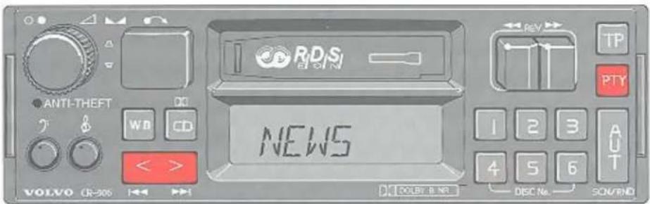
007L0569
Programme Type
The "PTY" function enables you to choose different types of programme. If you want to search for a desired programme type, do as follows:
- Push the "PTY" button for less than 0.9 seconds. The tuned programme type will be displayed.
- By pressing the tuning button for less than 0.9 seconds at a time, it is possible to scroll the different programme types.
- When you have found a programme type you want to select, press the tuning button or the PTY button for more than 0.9 seconds to start searching for the selected programme type. An asterisk in the display will confirm your choice. While searching "WAIT" is displayed. If the desired programme type is found, its name is displayed for 5 seconds.
-
If no station with the desired programme type is found "NO PTY" will be displayed for 5 seconds and the radio returns to the previous station.
-
When you scroll the different programme types, you can also choose between "SPEECH" and "MUSIC". "SPEECH" contains programme types 1–9. "MUSIC" contains programme types 10–15.
-
If you always rapidly want to have access to a certain kind of programme type, do as follows: press the "PTY" button for less than 0.9 seconds. Select the desired programme type. You may then store this programme type by pressing one of the preset-buttons for more than 0.9 seconds. When you want access to your prestored programme type, press the "PTY" button for less than 0.9 seconds and then the chosen preset-button. The programme type will be displayed. Press once more the "PTY" button for less than 0.9 seconds. An asterisk in the display will confirm your choice.
Programme Type Priority \*

00/12/2014
Programme Type – Priority
- If you press the "PTY" button for more than 0.9 seconds Priority Mode will be selected. The small "PTY PRI" text is displayed.
- "PTY-PRIO" is displayed for 2 seconds and then the current programme type is displayed for 2 seconds. After this the previously chosen programme type is shown for 3 seconds.
- Then press the tuning button for less than 0.9 seconds to search for and select the programme type you desire.
- When you have found a programme type you want to give priority to, press the tuning button for more than 0.9 seconds. An asterisk in the display will confirm your choice. You can give priority to more than one programme type.
* Not applicable in Australia
- During storing "PTY SET" is displayed for 2 seconds and then the selected programme types are displayed for 1 second each.
- The radio now returns to the previous mode and searches for the selected programme type by means of EON information. If the selected programme type is not found immediately, the search is continued and as soon as the selected programme type is found, the radio switches to that station. A small "P" is displayed in the channel indicator.
- If you always rapidly want to have access to a certain kind of programme type, do as follows: press the "PTY" button for less than 0.9 seconds. Select the desired programme type. You may then store this programme type by pressing one of the preset-buttons for more than 0.9 seconds. When you want access to your prestored programme type, press the "PTY" button for more than 0.9 seconds and then the chosen preset-button. The programme type will be displayed. Press once more the "PTY" button for less than 0.9 seconds. An asterisk in the display will confirm your choice.
Programme Type Priority \*

06AL0104
Programme Type – Priority
- If you want to erase all previously chosen priorities, select "ALL-CLEAR" and press the tuning button for more than 0.9 seconds.
-
If you want to erase one of the previously chosen priorities, press the PTY button when the programme type is shown in the display. The asterisk will also disappear.
-
When you scroll the different programme types, you can also choose between "SPEECH" and "MUSIC". "SPEECH" contains programme types 1–9. "MUSIC" contains programme types 10–15.
- Priority Mode will, as TP Mode, break through tape or CD mode. If for instance you have given priority to News, the tape deck or the CD will be interrupted and the News will be received.
- If you want to disregard a chosen programme type when it breaks through, press the "PTY" button for less than 0.9 seconds.
Cassette deck

ODAI LOGIS
A - Cassette slot
The cassette is inserted with the open side to the right (side 1 or A of the cassette upwards). When the cassette is inserted, the radio is disengaged and the cassette will start to play automatically. "TAPE → "or" ← TAPE' is displayed to indicate which side of the tape is being played. When one side of the tape has been played the unit will automatically play the other side (auto-reverse). The cassette can be inserted or ejected even when the unit is switched off.
B - Reversing the tape
Press both "REV" buttons to reverse the direction of the tape (to play the other side of the tape). The tape direction is displayed.
C - Fast winding
Press either button to wind the tape. If the button you press is fully pressed, fast winding will go on to the end of the tape. The other side of the tape will then be played.
Cassette deck

A - Cassette eject
Press the button to stop the tape and to eject the cassette. The radio will then automatically re-engage, and the latest station listened to will be received.
B - Dolby B NR - noise reduction system
This set has DOLBY B NR Noise Reduction system for tape playback. The Dolby Noise Reduction function is engaged when the Dolby double-D symbol is shown in the display. Press the CD button for more than 0.9 seconds when you want to engage/disengage the Dolby Noise Reduction function.

A - CD mode selector
Press CD to activate CD mode. The disc/track last listened to will start to play again. If the CD-changer cartridge ^8 is empty “--” will be displayed. If a selected disc position is empty, the disc number and “--” will be displayed and the next disc will be automatically selected.
B - Disc number selector
Press one of the preset buttons to select the desired disc number. The selected disc number and track number will be displayed.
C - Track number selector
Press the tuning button for less than 0.9 seconds to select the track number desired. The chosen track number will be displayed.
* The functions pertaining to the CD changer are only applicable if the unit has been connected to the Volvo CD-changer which is sold separately as an accessory. IF no CD-changer is connected to the unit "CD E-EE" will be displayed if you happen to choose CD mode.
D - Music Search
Press the tuning button for more than 0.9 seconds to search within the track. During searching you can hear the music being played at faster speed. The played time is displayed at the same time.

A - Scan choice
Press AUT button for less than 0.9 seconds. Music will be played from each track of each disc for 10 seconds. "SCN" will be displayed.
B - Random choice
Press AUT for more than 0.9 seconds to activate random mode. From a disc chosen at random, 4 tracks will be played (also chosen at random). A new disc will then be played in the same way. "RND" will be displayed when this function is engaged.
C - To re-enter previous mode
If you press the CD button, you will reenter the mode used most recently (tape or radio).
CD changer

natural_image
Technical line drawing of a mechanical assembly with labeled components (no text or symbols)CD changer
The CD changer, which is available separately, is loaded with a cartridge containing 6 discs. Extra cartridges are available from your Volvo dealer.
Insert the disc into the cartridge with the label up. Insert the cartridge and close the cover. Eject the cartridge by pressing the eject button. Remove the discs by pressing the lock tabs.
The cartridge can be inserted or ejected even when the unit is switched off.
Operating tips
- Before using a new disc for the first time, remove any burrs at the centre/outer edge by running the stem of a pen or similar object around the hole/edge of the disc.
• Use high quality discs only. - Keep the discs clean. Wipe them with a soft, clean, lint-free cloth, working from the centre outwards. If necessary, moisten the cloth with a neutral soap solution. Dry thoroughly before using.
- Never use cleaning spray or anti-static liquid. Use only cleaner specifically made for CD discs.
- Use discs of the correct size only (3.5" discs should never be used).
• Do not put tape or labels on the disc itself. - Condensation may occur on discs/optical components in the changer in cold winter weather. The disc can be dried with a clean, lint-free cloth. Optical components in the CD-changer may, however, take up to one hour to dry off.
- Never attempt to play a disc which is damaged in any way.
- When not in use, discs should be stored in their covers. Avoid storing discs in excessive heat, direct sunlight or dusty locations.
General information
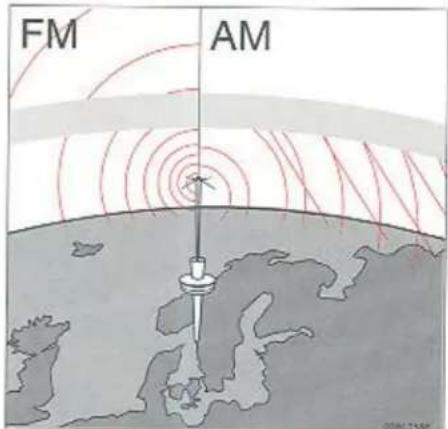

natural_image
Diagram showing a car on a road with concentric red wave patterns and a red object near the road (no text or symbols)
natural_image
Illustration of a car driving on a road with a building and radar system in the background (no text or symbols)Sending signals
The U(FM) waves do not follow the earth's surface, nor do they bounce off the atmosphere. For this reason their range is limited.
The M, L (AM) waves follow the earth's surface and reflect against the atmosphere. This gives them a wide range.
Weak reception (fading)
Because of the limited range of the U(FM) senders and the fact that these waves are very reflective this problem usually occurs with U(FM) reception. If the sender is blocked by buildings or mountains distortion can result.
Distortion
The reason why U(FM) but not M/L(AM) is audible in covered parking areas, under bridges etc., is that U(FM) signals reflect against solid objects such as buildings. Because these waves are very reflective multipath distortion can result. This distortion is the result of the reflected signal and the direct signal reaching your antenna at slightly different times causing a cancellation of all signals. This problems occurs largely in built-up areas.
Cross modulation, U-(FM) – reasons for distortion M/L(AM) – reasons for distortion

natural_image
Illustration of a car driving on a curved road with a red triangular light source, no text or symbols present
natural_image
Illustration of a person riding a car on a road with red exhaust plumes (no text or symbols)
natural_image
Cartoon illustration of a car with red lightning bolts emitting smoke or heat, against a cloudy sky (no text or symbols)Cross modulation
If you listen to a weak station in the vicinity of a stronger one both stations may be received simultaneously.
U(FM) - reasons for distortion
U(FM) is affected by the electrical systems of nearby vehicles, especially those without suppression. The distortion increases if the station is weak or poorly set. The U(FM) reception is not as sensitive to electrical disturbance as M/L(AM).
M/L(AM) - reasons for distortion
M/I.(AM) reception is sensitive to electrical disturbances such as power lines, lightning etc.
Radio
U(FM) stereo reception
Stereo reception places very high demands on the signal quality which means the types of distortions previously mentioned become even more obvious. The signal strength needs to be stronger for good stereo reception and this limits the effective range of the sender.
We hope that this information proves to be useful and provides you with a better understanding of the problems related to car radio reception.
Reception conditions are not always optimum and this is, of course, beyond our control.
However, we have endeavoured to make the Volvo Car Radio of a quality so that you can enjoy the best possible reception no matter what the reception conditions may be.
Radio antenna
NOTE: Always lower the antenna when using an automatic car wash or entering a garage. The antenna should be cleaned at least every 8,000 km or more frequently if needed. Use Volvo Cleaning Spray (1161030-0) for cleaning. Spray the antenna and wipe it clean and dry with a rag. Spray it again. Lower and raise the antenna. Wipe it clean and dry again. Lower and raise the antenna 4–6 times. Make sure it is dry and free from dirt/lubricating oil.
Radio aerial, 5-door model (certain markets)
The radio aerial is fitted to the left-hand side window of the boot area.
If your car has a factory-fitted audio system this aerial will also have an aerial booster. Note! The aerial will not work without an aerial booster.
Cassettes
Store cassettes in their cases or in Volvo's special cassette compartment, available as a genuine Volvo accessory.
Do not touch the tape surface with your fingers.
Tapes should not be exposed to direct sunlight, or extreme temperatures.
Keep tapes away from oil, grease and other contaminants.
For optimal tape deck performance Volvo does not recommend the use of C-120 tapes.
Take up slack using a pen or a pencil before inserting cassette in cassette slot.
Cleaning cassette
We recommend the use of Volvo Cleaning Cassette available as a genuine Volvo accessory. Regular use improves sound quality, cleans vital parts and prevent tape tangle.
Make sure that the aerial wires on the inside of the window cannot be damaged by objects placed near them. When cleaning the window be careful that the wires are not scratched by rings etc. If they are damaged, radio reception will be impaired.
Technical specifications
Technical Specifications - CR-906
Volvo's CR-906 Cassette Radio is a microprocessor radio with PLL (Phase Lock Loop), designed for the Radio Data System (RDS). The radio has an internal 4 x 20 W amplifier for the door speakers. The dashboard speakers are connected with an internal filter to the front door speaker amplifier.
Note: Use only Volvo Treble Speakers for the dashboard.
Radio
| Power output: | 4 x 20 W (10% dist.) |
| Output impedance: | 4 Ohms |
| System voltage: | 12 Volts, negative ground |
| Fuse: | 10 A |
| Frequency range: | U (FM) 87.5–108 MHzM (AM) 522–1611 kHzL (AM) 153–281 kHz |
| Sensitivity: | U (FM) 1.5 μVM (AM) 6.5 μVL (AM) 30.0 μV |
Cassette deck
| Tape speed: | 4.76 cm/sec. |
| Pinch-off | |
| Channel separation | 40 dB |
| Frequency range | 30–15,000 Hz |
| S/N (120μs) | 50 dB |
| Wow and flutter | < 0.08% |
Alarm
"Alarm!" - will be displayed when an alarm message is broadcast.
This function is used to alert drivers after a serious accident or catastrophe, i.e. nuclear power plant break-down or collapsed bridge, etc.
Dolby noise reduction manufactured under license from Dolby Laboratories Licensing Corporation. "Dolby" and the double D symbol □□ are the trademarks of Dolby Laboratories Licensing Corporation.
Alphabetical index
| ABS | 3:13 |
| Air vents | 1:13 |
| Airbag (SRS) | 2:26 |
| Air conditioning | 1:13 |
| Air pressure, tyres | 4:3 |
| Alarm | 2:6 |
| Alternator belt tension | 7:11 |
| Alternator | 8:6 |
| Anti-corrosion treatment | 6:2 |
| Anti-freeze fluid | 7:10 |
| Ashtrays | 1:11 |
| Automatic car washes | 6:7 |
| Automatic transmission | 3:6 |
| Backrest, adjustment | 2:8 |
| Battery | 7:3 |
| Battery electrolyte | 8:7 |
| Body and interior | 2:1 |
| Bodywork care | 7:9 |
| Bodywork lubricating points | 7:9 |
| Bonnet lock | 2:13 |
| Bonnet, opening | 2:13 |
| Boot | 2:3 |
| Boot illumination, use | 2:14 |
| Brake fluid | 7:8 |
| Brake warning lamps | 1:4 |
| Brake control lamps | 1:4 |
| Brake light, high-level, bulb replacement | 5:1 |
| Brake light, bulb replacement | 5:10 |
| Brakes | 3:1 |
| Bulbs, replacement | 5: |
| Car washes | 6:7 |
| Carpets, cleaning | 6:8 |
| Catalytic converter | 9:2 |
| Central locking | 2:2 |
| Changing wheels | 5:6 |
| Changing wiper blades | 7:13 |
| Chassis number | 8:2 |
| Checking the oil, automatic transmission | 7:5 |
| Checking the coolant | 7:10 |
| Child safety | 2:22 |
| Child safety lock | 2:3 |
| Children in cars | 2:22 |
| Cigar lighter | 1:11 |
| Cleaning | 6:6 |
| Climate unit | 1:13 |
| Clock | 1:2 |
| Clutch | 7:8 |
| Colour code | 6:4 |
| Combined instrument, Indicator lamps | 1:3 |
| Coolant | 7:10 |
| Cooling system | 7:10 |
| Courtesy lighting, use | 2:11 |
| bulb replacement | 5:15 |
| Crankcase ventilation | 9:3 |
| Defroster | 1:16 |
| Dimensions and weights | 8:3 |
| Dipstick, engine oil | 7:6 |
| Dipstick, automatic transmission | 7:5 |
| Direction indicators, use | 1:6 |
| Direction indicators, replacement of bulbs | 5:5 |
| Door open warning lamps | 2:1 |
| Bulb replacement | 5:1 |
| Doors | 2:1 |
| Drainage holes | 7:6 |
| Draining plug, engine oil | 6:6 |
| Draining water | 7:15 |
| Driver's seat | 2:8 |
| Driving with a trailer | 3:15 |
| Driving characteristics | 3:9 |
| Driving abroad | 3:17 |
| Driving instructions | 3:1 |
| Economical driving | 3.3 |
| Electrical system, specifications | 8:6 |
| Electrically heated rear window | 1:8 |
| Electrically operated window winders | 1:12 |
| Electronic start inhibitor | 2:2 |
| Emergency measures | 5:1 |
| Emission control | 9:1 |
| Engine | 7:6 |
| Engine, specifications | 8:7 |
| Engine serial number | 8:2 |
| Engine, oil check | 7:6 |
| Engine oil, inspection, change | 7:6 |
| Engine oil filter | 7:6 |
| Expansion tank, cooling system | 7:10 |
| Fan belts | 7:11 |
| Folding rear seat | 2:18 |
| Fore/aft adjustment, front seats | 2:8 |
| Fresh-air intake | 1:13 |
| Front seats | 2:8 |
| Fuel, filling of unleaded fuel | 3:1 |
| Fuel, filling | 3:1 |
| Fuel gauge | 1:1 |
| Fuel economy | 3:1 |
| Fuses | 5:1 |
from selector automatic transmission 3:6
Gear selector, automatic gearbox 3:5
manual gearbox 3:5
Gearbox, manual, positions
Gearbox, automatic transmission
Gearchanging, manual gearbox 3:5 manual gearbox 7:10
Glycol 1:11
Handbrake 1:6
Handobrake Handobrake warning flashers, use 5:9
Hazard warning
bulb replacement
Headlamp flasher, use
Headlamp washer/w/put,
Headlamps, switches
bulb replacement 1:1
Heated seats 1:15
Heating and ventilation 2:8
Height adjustment, from seats 8:2
Identification, type designations, type school lock
Ignition and steering wheel roof 2:2
Ignition key 8:
Agitation system 5:
Ignition system In case of emergency 1:
In case of the lighting
Instruments
Instrumental, intermittent wiping, windscreen wip
Jack, use 7:3
Jacking up the car 7-3
Jacking points 2:14
Jacking power 2.14 Lock storage 3.12
Jack storage 3:12 I am leads 3:12
Jump leads 3.12 down starting battery, leads 2.2
Jump-starting, balance
Keys 5:7
Kick-down 9:2
Lambda-sond 1:6
Lamin controls
Lamp Conna
Lifting the car
Loading space
Locks
Long trips, inspection
Long loads
Lubricants
Lubrication, bodywork
Luggage area
bulb replacement 2:14
- Management 2:8
Luggage support, front seats
Main beam indicator, hashing method 1:6
Main beam control level
2 Main/dipped service 8:
7 Maintenance, 2:1
Maximum load
Mirrors
Number plate light
Octane ruling 1:2
Odometer 7:6
Oil filter 7:6
Oil change, engine 1:4
Oil pressure 7:5
Oil 6:4
Paintwork, touching-up 1:11
Parking brake 5:11
bulb replacement 1:7
Parking lights, use 2:12
Parking ticket clip 3:2
Petrol filling 6:7
Polishing 7:8
Power steering 5:6
Power 8:
Punctures Ratio final drive 2:1
Ratio, ratio used standing lights, use 2:16
Reading Highway 1:9
Rear doors window wiper 1:9
Rear window wip 5:10
Rear fog lamp, and bulb replacement
in dry heater 2:10
Rear window mirrors 6:8
Rear-view (mitions) 5:18
Removal of stains 10:37 Bulbs 7:1
Replacement, but not of wiper blades
Replacement of wip 5:1
Reverse gear bulb, bulb replacement 3:17
Reversing Taftup: 3:2
Roof racks
Running-in


- Instruments
- Outside temperature gauge (option)
- Fuel gauge
- Quartz clock
- Speedometer
- Odometer
- Tripmeter Resetting of trip meter
- Tachometer
- Boost pressure gauge
- Temperature gauge
- Warning lamps
- Brake circuit failure
- Low oil pressure
- Bulb failure
- Fault in exhaust emission control system
- Battery charge failure
- Anti-lock Braking System (ABS)
- Airbag (SRS)
- Direction indicators, main/dipped beams and headlamp flasher
- Hazard warning lamps
- Windscreen wash/wipe, Headlamps, Ignition switch/steering wheel lock
- Windscreen wash/wipe, headlamp wash/wipe
- Lock position
- I Intermediate position "Radio"
- II Drive
- III Start position
- Headlamps and parking lights
- All lights off
- Parking lights and Dim dip on.
- Electric sun roof, Heated rear window
- Sun roof
- Heated rear window
- Instrument illumination regulator
- Front and rear foglamps, Tailgate wash/wipe, estate
- Front foglight
- Tailgate wash/wipe, estate
- Rear foglight
- Heated front seats
- Parking brake, Cigar lighter, Ashtrays
- Parking brake
- Cigar lighter and ashtrays
- Electrically operated window winders Right front Right rear
- WARNING!
- Heating and ventilation – climate units
- Protecting the environment
- Heating and ventilation
- Heating and ventilation system without air conditioning
- Mode selector
- Heating and ventilation system with manual air conditioning
- Fan
- Temperature selector
- A few supplementary hints:
- Heating and ventilation with automatic air conditioning
- Temperature
- Automatic setting:
- Optimum demist:
- Indication of fault in the climate unit
- Difficult weather conditions
- Electrically operated sun roof
- Overload protector
- Sun visor
- Body and interior
- Keys
- Electronic start inhibitor (Immobilizer)
- Number tag
- Locking and unlocking doors with central locking
- Boot lock
- Child safety lock
- Remote-controlled central locking without alarm (certain markets)
- Remote-controlled central locking (extra equipment)
- Unlocking
- Locked position (Locking)
- Points to remember
- Locking and unlocking with the key
- The small button
- Cars with electronic start inhibitor
- Programming new remote controls
- Remote-controlled central locking with alarm (certain markets)
- Activating your alarm
- Deactivating your alarm
- NOTE!
- Disconnecting the entire alarm system
- Disconnecting the sensors
- Front seats
- Height adjustment
- Height adjustment passenger's seat
- Forward-backward adjustment
- Electrically operated front seats
- Electrically controlled driver and passenger seats without memory function
- Electrically operated seats with memory function Programming:
- Stop button
- Setting:
- Emergency stop (seat with memory function)
- Ignition key
- Rear view mirrors
- Rear view mirror
- Manually adjustable door mirrors
- Electrically adjustable door mirrors (optional)
- Courtesy lighting, Reading lights, Door switches
- Courtesy lighting, Reading lights
- Cars with automatic air conditioning
- Door switches
- Storage compartments
- CAUTION!
- To open the bonnet
- Boot 4-door models
- Boot light
- Boot hatch
- Tailgate
- Cargo space, Estate
- Tool box
- Spare tyre and jack
- Cargo space light
- Folding rear seat down Extending luggage area
- Removing seat cushions
- Securing cargo
- Seat belts
- Seat belts should always be worn
- To fasten:
- To release:
- Seat belt check
- Head restraint, rear seat
- Child safety
- Children aged up to about 3
- Children aged 3 and older
- Important hints!
- Pregnant women
- Booster cushion
- Folding away the booster cushion
- Airbag (SRS) SIPS bag
- SRS (airbag) and SIPS (side impact airbag)
- The SRS System (airbags in the steering wheel and in the dashboard)
- Seat belts with seat belt tensioners
- SIPS bag system (side impact airbags)
- Passenger's SRS (Airbag)
- SIPS bag
- Child seat and child booster cushion
- When are the airbags deployed
- The heart of Volvo's safety system
- Cargo space 5-door model. Loading
- Loading in loading area
- Remember the following when loading the car:
- Luggage compartment, 5-door model - Cargo net
- Cargo net
- Cargo net and extra rear-facing child seat
- When removing the cargo net:
- Luggage compartment, 5-door model - Luggage cover
- Luggage cover
- Removing luggage cover (see picture)
- Child Restraint Anchorages (Australia)
- Starting and driving
- Refuelling
- Your new car – slippery roads
- Running-in
- Use the correct petrol
- Economical driving
- Vehicle condition
- Warning! Catalytic converter
- Starting the engine
- Injection engine
- Starting en engine with an electronic start inhibitor
- Cold-starts at high altitude
- CAUTION CARBON MONOXIDE!
- Manual gearbox M-90
- Reverse gear inhibitor M-90
- Gear positions, manual gearbox
- Reverse gear catch
- Automatic transmission
- P Park
- R Reverse
- N Neutral
- D Drive
- Lock-up function
- Second
- First
- Selector lever operation
- Kick-down
- Selector lever operation (AW)
- Starting
- Towing a caravan or trailer Automatic transmission
- Weight distribution affects handling
- Handling, road holding and tyres
- Do not drive with the boot open
- Overheating
- Automatic differential lock\*
- Cruise Control
- Engagement
- To set the desired speed:
- Reducing speed
- Acceleration
- Disengagement
- Towing
- Especially for automatic transmissions
- Starting the engine by towing
- Jump starting
- Brakes
- Should there be a malfunction in a brake circuit, a red warning light will come on
- The brake servo functions only when the engine is running
- Moisture on brake discs and brake pads may affect braking
- Severe strain on the brake system
- ABS brakes
- Winter driving
- Towing a caravan or trailer
- Towing a caravan
- Extra oil cooler
- Long distance trips
- Roof racks
- Wheels and tyres
- Tread wear indicators
- How to improve tyre economy
- Flat spots
- Snow tyres, snow chains
- Tyres for winter use
- Special rims
- Inflation pressures and wear
- Tyre pressures
- Cold tyre pressures in kPa and (psi) \*
- General information, Spare tyre
- General information
- Changing wheels
- Temporary Spare (certain markets only)
- New tyres
- In case of emergency
- Troubleshooting
- Misfiring and erratic engine operation
- Faulty ignition system
- Ice in injection system
- Blocked air filter/fuel filter
- Car with electronic start inhibitor will not start
- The engine starts but stops immediately
- The engine does not start at all
- The engine does not start or is difficult to start
- The instructions for starting the motor on 3:4 have not been followed
- The battery is poorly charged or flat
- Poor contact in the electrical system
- No fuel reaching engine
- The key turns in the lock
- Troubleshooting, Fuse replacement
- Tyre imbalance or vibration during driving
- Engine overheats
- Malfunction of the sun roof
- Fuse replacement
- Number
- Amperage
- Removal
- Fitting
- Replacing bulbs
- Changing headlamp bulbs
- Headlamps
- Fog lights
- Main beam auxiliary light
- Changing bulbs, front
- Changing bulbs, tail
- Replacing tail light bulbs (estate)
- Side marker lights
- Door open warning lamps
- Number plate lighting
- 5-door model
- Cargo space light (estate)
- Courtesy lighting, reading lamps (certain models)
- High-level brake lights
- To remove:
- To fit:
- Estate
- Car care
- Corrosion protection
- Corrosion protection, inspection and touching-up
- The visible rustproofing
- Paintwork
- Colour code
- Minor stone chips and scratches
- Paintwork damage
- Washing the car
- Suitable detergents
- Bird droppings
- Washing
- Automatic car washing
- Polishing and waxing
- Bumper wraparound
- Cleaning the upholstery
- Removal of stains from cloth upholstery
- Removal of stains from vinyl
- Removal of stains from leather upholstery
- Removing stains from fabrics and floor mats
- Bear in mind
- Cleaning the seat belts
- Stain removers
- Use Volvo fabric cleaning kit or:
- Service – an investment!
- Volvo Service
- Pre-delivery service
- The Volvo Service Programme
- Remember
- Important
- Service manuals
- Jacking up the car Workshop jack
- Note the following before working on your car:
- Battery
- Environmental care
- Engine compartment
- Engine oil, checking, changing
- Check engine oil regularly when filling up
- Draining the oil
- To add or change engine oil
- Changing oil filter
- Oil quality:
- CCMC G5
- Capacity:
- Unfavourable conditions
- Brake fluid, Power-assisted steering fluid
- Brake fluid
- Power-assisted steering fluid
- Door stop (located at lower hinge)
- No. Lubricating point
- Lubricant
- Cooling system
- Coolant composition
- Different types of coolant should not be mixed together!
- Check the coolant regularly; it does not normally need to be replaced
- Changing the coolant
- To drain
- To fill
- Battery, Fan belts and drive belts
- Replacing fan belts
- Belt check
- Drive belts should be checked and adjusted by a Volvo dealer
- Washer nozzles, Washer reservoir
- Adjusting the washer nozzles
- Washer reservoir
- Wiper blades
- Replacing windscreen and tailgate wiper blades
- Replacing headlamp wiper blades \*
- Installation of accessories
- Installation of telephone and accessories
- Specifications
- Type designations
- Dimensions and weights
- Capacities in litres
- Unleaded fuel
- Fuel consumption
- Exhaust emission control
- Emission control
- Emission controls
- Catalytic converter
- Lambda-sond (oxygen sensor) system
- Exhaust gas regulation
- Positive crankcase ventilation
- Crankcase ventilation, inspection
- Fuel evaporation system
- Emission regulation service
- ... as regards service:
- ... as regards engine components:
- ... as regards the fuel system:
- ... as regards the ignition system:
- Audio
- RDS functions
- Radio Data System\*
- The following pages describe the function and operation of Volvo Cassette Radio CR-906
- Anti-theft code
- Code cards
- Using the code
- A - On/Off switch and volume control
- B - Waveband selector
- C - Manual tuning
- D - Seek tuning
- Radio
- A - Presetting
- B - Automatic programming (Autostore)
- A - Balance control
- B - Fader control
- C-Bass control
- D - Treble control
- AF Search function (automatic re-tuning)\*
- AF - search function (automatic re-tuning)
- Traffic Programme\*
- Traffic Programme (TP)
- Programme Types \*
- Programme Type
- Programme Type Priority \*
- Programme Type – Priority
- Cassette deck
- A - Cassette slot
- B - Reversing the tape
- C - Fast winding
- A - Cassette eject
- B - Dolby B NR - noise reduction system
- A - CD mode selector
- B - Disc number selector
- C - Track number selector
- D - Music Search
- A - Scan choice
- B - Random choice
- C - To re-enter previous mode
- CD changer
- Operating tips
- Sending signals
- Weak reception (fading)
- Distortion
- Cross modulation, U-(FM) – reasons for distortion M/L(AM) – reasons for distortion
- Cross modulation
- U(FM) - reasons for distortion
- M/L(AM) - reasons for distortion
- U(FM) stereo reception
- Radio antenna
- Radio aerial, 5-door model (certain markets)
- Cassettes
- Cleaning cassette
- Technical specifications
- Technical Specifications - CR-906
- Alarm
Marque : VOLVO
Modèle : 940 (1997)
Catégorie : Voiture