300 CE (1988) - Voiture Mercedes-Benz - Notice d'utilisation et mode d'emploi gratuit
Retrouvez gratuitement la notice de l'appareil 300 CE (1988) Mercedes-Benz au format PDF.

Questions des utilisateurs sur 300 CE (1988) Mercedes-Benz
0 question sur cet appareil. Repondez a celles que vous connaissez ou posez la votre.
Poser une nouvelle question sur cet appareil
Téléchargez la notice de votre Voiture au format PDF gratuitement ! Retrouvez votre notice 300 CE (1988) - Mercedes-Benz et reprennez votre appareil électronique en main. Sur cette page sont publiés tous les documents nécessaires à l'utilisation de votre appareil 300 CE (1988) de la marque Mercedes-Benz.
MODE D'EMPLOI 300 CE (1988) Mercedes-Benz
Owner's Manual

200
200 E
230E
260E
300 E
230 CE
300 CE
260 E 4MATIC
300 E 4MATIC
natural_image
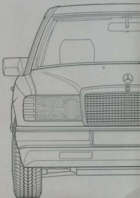
Line drawing of a classic Mercedes-Benz car front view showing grille and side brackets (no text or symbols)
natural_image
Blue icon of a fuel pump (no text or symbols)What You Need to Know at the Petrol Station
See last page
Drive Sensibly — Save Fuel
Fuel consumption depends largely on how the vehicle is driven and on the operating conditions.
In order to save fuel you should:
- ensure that tyre pressures are correct
not carry unnecessary loads - remove ski racks or roof-mounted luggage racks when not in use
not warm up your engine at idle and with the vehicle at standstill
● avoid frequent acceleration and deceleration - shift gears on time, do not exceed 23 of the individual gears' max. speeds
● have all the maintenance jobs specified by us carried out at regular intervals by a MERCEDES-BENZ service station.
For consumption data, refer to page 63
Owner's Manual

200
200 E
230 E
260 E
300 E
230 CE
300 CE
260 E 4MATIC
300 E 4MATIC
Type 124
natural_image
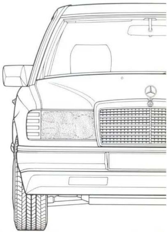
Line drawing of a Mercedes-Benz SUV front view showing grille, grille grilles, and tire tracks (no text or symbols)It is in your interest to observe the following:
We recommend using original MERCEDES-BENZ parts as well as converted parts and accessories explicitly approved for your vehicle model. These parts have been subjected to a special test in which their reliability, safety and their special suitability for MERCEDES-BENZ vehicles has been determined. Despite continuous observation of the market we cannot make this claim for other products and therefore refuse to be held liable for them, even if in individual cases an approval or an official authorization should be available.
MERCEDES-BENZ original parts and approved converted parts and accessories are available at your MERCEDES-BENZ service station where you will receive exhaustive advice – also on permissible technical modifications – and where workmanlike installation will be performed.
Printed in Germany
We reserve the right to modify the technical details of the vehicle as given in the data and illustrations of this Owner's Manual (s.e.e.o.). Reprinting, translation and copying, even of excerpts, is not permitted without our prior authorization in writing.
VKT/10.88.15/Ru
We at Daimler-Benz wish you much pleasure with your new car.
You have bought a MERCEDES car, and you have a right to expect it to run troublefree and for a very long time whilst being as easy as possible to operate.
Our service department staff have one request to make — for your own benefit:
Please do not put this Owner's Manual aside without reading it. It will offer you a great deal of important information which will assist you in the operation of your MERCEDES car and make driving even more enjoyable.
We wish you pleasant driving Daimler-Benz Aktiengesellschaft
This Owner's Manual also includes descriptions of optional equipment as far as instructions are required for its operation. Since the scope of the parts supplied depends on the order specifications, the equipment of your vehicle may deviate from some of the descriptions and illustrations.
Should your vehicle be provided with equipment which is not described or illustrated in this Owner's Manual, your MERCEDES-BENZ service station will instruct you on the correct operation of and the service measures for it.
Owner's Manual and Maintenance Booklet are important documents and should always be carried in the vehicle.
Instruments and Controls
Starting the Engine
Driving Instructions
Vehicle Maintenance
Operation
Driving
Practical Tips
Technical Data
Service Products
Key Word Index
Check the Following Items Regularly and Before Every Long Journey
See page 136
The First 1500 km
The more carefully you treat the engine at the beginning, the more satisfied you will be with its performance later on. Therefore, during the first 1500 km you should drive at varying speeds and engine revolutions.
Avoid placing heavy loads on the engine during this time (driving flat out) and high engine revolutions (max. 23 of permissible speed in any gear).
Change gear in good time!
On vehicles with automatic transmission, avoid kickdown and do n change down by hand for braking possible. Engage selector lever position "3" or "2" only when travelling slowly (on mountain passes).
As of 1500 km, slowly increase to full road speed and/or maximum engine speed.
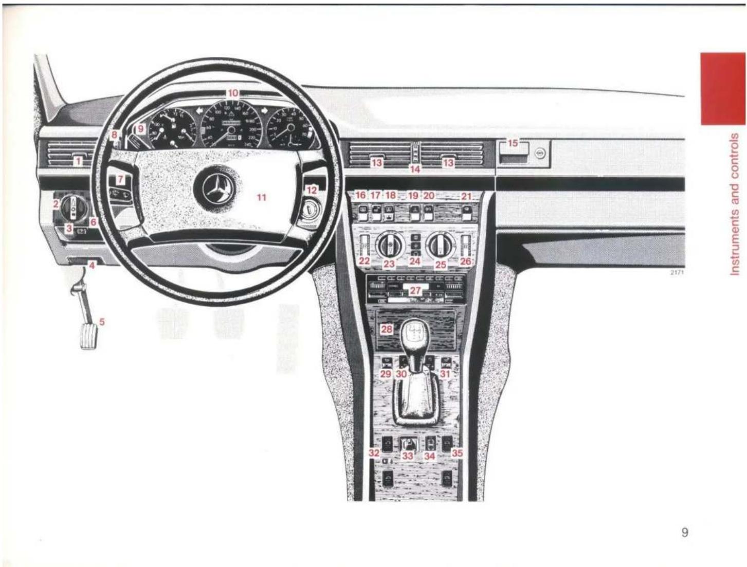
Instruments and Controls Starting the Engine Driving Instructions Vehicle Maintenance
Driving Instructions 15
Indicator Lamp Symbols 13
Instrument Cluster 12
Instruments and Controls Left-hand drive vehicle 8
Right-hand drive vehicle 10
MERCEDES-BENZ Maintenance System 17
Starting and Stopping the Engine 14
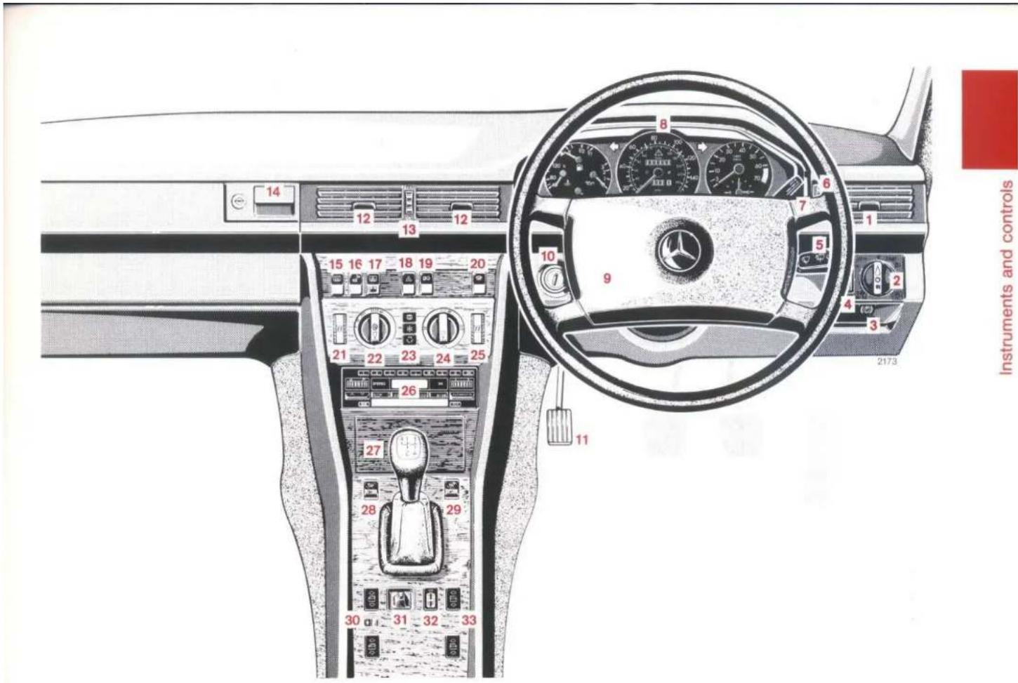
Instruments and Controls
Left-hand drive vehicle
For more detailed descriptions see quoted pages.
1 Swivelling air outlets for side ventilation (page 20)
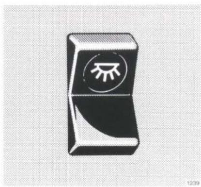
2 Lighting switch (page 49)
3 Parking brake release handle (page 58)
4 Bonnet lock release handle (page 76)
5 Parking brake pedal (page 58)
6 Headlamp beam control (page 50)
7 Combination switch (page 51)
8 Adjusting wheel for side ventilation (page 20)
9 Tempomat (page 62)
10 Instrument cluster (page 12)
11 Horn control
12 Steering lock with ignition/starter switch (page 48)
13 Swivelling air outlets for non-heated fresh air (page 20)
14 Adjusting wheel for non-heated fresh air (page 20)
15 Glove box (lighted only with the steering lock key in position 1 or 2) is eliminated on vehicles equipped with front passenger airbag.
16 Switch for heated rear window (page 54)
17 Switch for letting down safety headrests in rear passenger compartment (page 40)
18 Switch for rear window blind
19 Switch for hazard warning flasher system
20 Fanfare horn control
21 Switch for rear passenger compartment lamp (page 55)
22 Temperature selector for heating left vehicle side (page 20)
23 Air volume control knob (page 20)
24 Key board for air conditioning system (page 25)
25 Air distributor switch (page 20)
26 Temperature selector for heating right vehicle side (page 20)
27 Radio
28 Ashtray with cigar lighter (pages 53, 98)
29 Switch for left front seat heater (page 38)
30 Supplementary heater (page 23)
31 Switch for right front seat heater (page 38)
32 Switch group for window lifts, left side (page 56)
33 Adjusting lever for exterior mirror on front passenger side (page 52)
34 Speaker - fader control knob
35 Switch group for window lifts, right side (page 56)
text_image
10 8 9 11 12 13 14 15 16 17 18 19 20 21 22 23 24 25 26 27 28 29 30 31 32 33 34 35 Instruments and controls 9Instruments and Controls
Right-hand drive vehicle
For more detailed descriptions see quoted pages.
1 Swivelling air outlets for side ventilation (page 20)
2 Lighting switch (page 49)
3 Parking brake release handle (page 58)
4 Headlamp beam control (page 50)
5 Combination switch (page 51)
6 Adjusting wheel for side ventilation (page 20)
7 Tempomat (page 62)
8 Instrument cluster (page 12)
9 Horn control
10 Steering lock with ignition/starter switch (page 48)
11 Parking brake pedal (page 58)
12 Swivelling air outlets for non-heated fresh air (page 20)
13 Adjusting wheel for non-heated fresh air (page 20)
14 Glove box (lighted only with the steering lock key in position 1 or 2) is eliminated on vehicles equipped with front passenger airbag.
15 Switch for heated rear window (page 54)
16 Switch for letting down safety headrests in rear passenger compartment (page 40)
17 Switch for rear window blind
18 Switch for hazard warning flasher system
19 Fanfare horn control
20 Switch for rear passenger compartment lamp (page 55)
21 Temperature selector for heating left vehicle side (page 20)
22 Air volume control knob (page 20)
23 Key board for air conditioning system (page 25)
24 Air distributor switch (page 20)
25 Temperature selector for heating right vehicle side (page 20)
26 Radio
27 Ashtray with cigar lighter (pages 53, 98)
28 Switch for left front seat heater (page 38)
29 Switch for right front seat heater (page 38)
30 Switch group for window lifts, left side (page 56)
31 Adjusting lever for exterior mirror on front passenger side (page 52)
32 Speaker - fader control knob
33 Switch group for window lifts, right side (page 56)
text_image
14 12 13 15 16 17 18 19 20 21 22 23 24 25 26 27 28 29 30 31 32 33 8 6 7 1 5 9 4 3 2173 11 Instruments and controls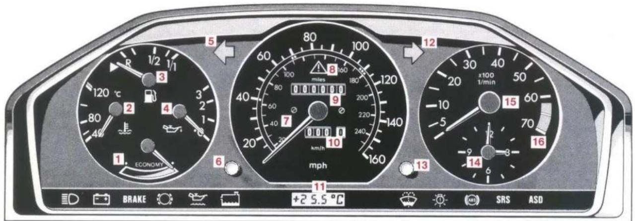
text_image
5 1/2 1/1 R 3 120 °C 2 4 80 40 ECONOMY 1 6 ECONOMY 80 100 100 100 180 200 220 240 260 280 300 320 340 360 380 400 420 440 460 480 500 520 540 560 580 600 620 640 660 680 700 720 740 760 780 800 820 840 860 880 900 920 940 960 980 1000 1020 1040 1060 1080 1100 1120 1140 1160 1180 1200 1220 1240 1260 1280 1300 1320 1340 1360 1380 1400 1420 1440 1460 1480 1500 x100 1/min 15 60 70 16 14 6 5 4 3 2 1 0 9 8 7 6 5 4 3 2 1 0 9 8 7 6 5 4 3 2 1 0 9 8 7 6 5 4 3 2 1 0 9 8 7 6 5 4 3 2 1 0 9 8 7 6 5 4 3 2 1 0 9Instrument Cluster
1 Gauge for economical driving. See page 65
2 Coolant temperature gauge. See page 67
3 Fuel gauge with reserve warning lamp, yellow. See page 68
4 Oil pressure gauge, bar gauge pressure. See page 66
5 Turn signal indicator lamp, left (green)
6 Knob for instrument lamps and trip odometer
Rotate knob: instrument lamps are infinitely variable
Depress knob: trip odometer is turned back
7 Speedometer
8 ASD operation indicator lamp, yellow. See page 70
Vehicles with 4MATIC: 4MATIC operation indicator lamp, yellow. See page 71
9 Total odometer
10 Trip odometer
11 Outside temperature gauge. See page 68
12 Turn signal indicator lamp, right (green)
13 Knob for clock pointers (press in for adjustments)
14 Electric clock
15 Tachometer
16 Engine overspeed range. See page 66
Indicator Lamp Symbols
Operation indicator lamp

Main beam on
Warning lamps
(must go out while the engine is running)

Battery is not being charged.
See page 66

Brake fluid level too low, parking brake tightened.
See pages 58, 69

Brake pads worn.
See page 68

Engine oil level too low.
See page 66

Coolant level too low. See page 67

Water level for windscreen washer and headlamp cleaning systems too low. See page 68

One of vehicle exterior light bulbs has failed. See page 67

ABS defective. See page 68

Airbag defective. See page 46

ASD defective. See page 70

4MATIC defective. See page 71

Starting and Stopping the Engine
Before starting the engine, be sure the parking brake is engaged.
Move gearshift lever to neutral (selector lever positions "P" or "N" on automatic transmissions).
Turn key in steering lock to position 2. The charge indicator lamp must come on.
Cold Engine
Briefly depress accelerator once (only on model 200). Turn key in steering lock clockwise to the stop and release only after the engine is firing regularly. Do not depress the accelerator during the starting process.
Engine at Operating Temperature
Turn key in steering lock clockwise to the stop. Do not depress the accelerator. If the engine fails to start after approximately 4 seconds, fully depress accelerator and continue to crank until the engine fires regularly. Release the key and ease off the accelerator.
At very high coolant temperatures the starting time can be reduced if the accelerator is depressed slowly from the very beginning of the starting process.
Switching Off
Turn the key in the steering lock to 0 and only remove the key when the vehicle is at a standstill.
If the coolant temperature is very high (e.g. after driving on a mountain pass), do not switch off the engine immediately but allow it to idle for approximately another minute at idle speed.
Notes:
Due to the installed starter non-repeat unit the key in the steering lock must be returned to the 0 position before a new starting attempt is made.
Observe the oil pressure gauge immediately after starting the engine. In a very cold engine the oil pressure will only rise slowly, some time after the engine has started. Do not rev up the engine before pressure is registered on the pressure gauge.
The charge indicator lamp must go out as soon as the engine has started.
Model 200: At high altitudes the engine must be revved up briefly (approximately 5 seconds at approximately 2000/min) after starting.
In areas where temperatures frequently drop below -25 °C, we recommend you to have a coolant preheater installed. Every MERCEDES-BENZ service station will readily advise you on this subject.
Driving Instructions
Servo Assistance
As long as the engine is not running there is no servo assistance for the service brake and the power steering. Keep in mind that in such an instance substantially greater power must be exerted for braking and more effort is required for steering.
Tyres
Do not allow your tyres to wear down too far. With less than 3 mm of tread the skid resistance on a wet road falls off sharply.
Depending upon the weather and/or road pavement the grip of the tyres varies widely.
The retention of the specified tyre pressure is essential. This applies particularly if the tyres are subjected to high loads (e.g. high speeds, heavy loads, high ambient temperatures).
Aquaplaning
Depending on the depth of the water layer on the road, aquaplan-ing may occur even with tyres still showing the full tread depth, and even at low speeds. Avoid track grooves in the road and apply brakes cautiously in the rain.
Tyre Grip
A given speed at which a vehicle driven on dry roads can still be fully controlled must be reduced when the same vehicle is to be driven safely on a wet or icy road.
You should pay particular attention to the condition of the road as soon as the prevailing temperatures fall close to the freezing point.
If ice has formed on the road (e.g. due to fog), a thin film of water is then quickly produced on the ice which substantially reduces the grip of the tyres. Under such weather conditions, drive, steer and brake particularly carefully.
We recommend M + S radial-ply tyres for the winter. On black ice or packed snow they can reduce your stopping distance as compared with summer tyres. Stopping distance, however, is still considerably greater than when the road is wet or dry.
Brakes
Relieve brakes when driving down long and steep gradients by engaging a lower speed (selector lever position "3" or "2" in the case of automatic transmissions). This prevents overheating of the brakes and reduces brake pad wear.
After sharp braking it is advisable not to switch off the engine right away, but to drive on for a short time to enable the air stream to cool down the brakes more quickly.
When driving in heavy rain for some time without applying the brakes, the first braking action may be somewhat retarded and increased pedal pressure may be necessary. For this reason, stay further away from vehicle in front.
In order to prevent corrosion on the brake discs, brake vehicle noticeably after a ride on a wet road (in particular when thawing salts are used) in order that the heated brake discs will dry before the vehicle is parked.
If only moderate use is made of the brake system as a result of the prevailing operating conditions, (e.g. city driving) you should check its efficiency by occasionally braking hard at high vehicle speeds. In doing this, endangering other road users. This will also improve the grip of the brake pads.
If the brake warning lamp in the instrument cluster comes on although the parking brake is released, this indicates a low fluid level in the brake fluid reservoir.
Brake pad wear or a leak in the system may be the reason for loss of brake fluid in the reservoir.
Have the brake system inspected at a MERCEDES-BENZ service station without delay.
Install only brake pads recommended by us. If other than recommended brake pads are installed the braking properties of the vehicle can be affected to an extent that the safety is substantially impaired.
Driving Instructions for Slippery Roads
The most important rule for icy roads is to drive sensibly and avoid abrupt acceleration, braking and steering action.
When the vehicle is in danger of skidding, declutch or – in case of an automatic transmission – move selector lever to position "N". Try to keep the vehicle under control by means of corrective steering action.
Road salts can adversely affect braking efficiency. Increased pedal force may become necessary to produce the normal brake effect. We therefore recommend depressing the brake pedal repeatedly when travelling on salt-strewn roads at length. This can bring road salt impaired braking efficiency back to normal. A prerequisite is, however, that this is possible without endangering other drivers on the road.
If the vehicle is parked after being driven on salt treated roads, the braking efficiency should be tested as soon as possible after driving is resumed while adhering to the safety requirements. Should the braking efficiency have deteriorated considerably it can be improved again by braking several times.
MERCEDES-BENZ
Maintenance System
You have been given a maintenance booklet with your vehicle in which all maintenance jobs are listed. In the saloon the maintenance booklet is in the vehicle document bag. In the coupé it is kept in the left door trim panel. The next service date is shown in the display.
The maintenance jobs must be carried out at the following intervals:
Routine Maintenance
Inspection at 1000 – 1500 km Service jobs every 10 000 km Maintenance jobs every 20 000 km Additional work every 60 000 km
In the vehicle covers only a short mileage, maintenance must be carried out after 2 years at the latest.
Engine Oil and Filter Change
Every 10 000 km, but at least once a year (autumn), if year-round oil is used. Otherwise at least twice a year (spring and autumn).
For recommended engine oil viscosities see page 125.
Rigorous Operating Conditions
In the case of rigorous operating conditions or heavy use it may be necessary to perform the maintenance jobs at shorter intervals, for example:
Engine oil and filter change every 5000 km
Automatic transmission: Fluid change without filter change every 30 000 km
Inspect tyres
Air cleaner – clean or renew element. For air cleaners with maintenance indicator, refer to "Practical Tips" on page 77.
Note:
Examples of rigorous operating conditions or heavy use are: mainly city or short distance traffic, frequent mountain driving, poor road conditions, dust and mud, trailer operation.
Special Maintenance Measures
Renew brake fluid once a year, preferably in spring.
Have coolant renewed every three years (see "Service Products").
Have vehicle underside checked once a year (preferably in summer) for damage caused by road salt and repair underside protection, if necessary, using an approved protective wax.
Body Cavity Preservation
The body cavities of your vehicle have been preserved permanently in the works. We do not recommend repeating this body preservation.
Certificates
Please have the work carried out confirmed in the maintenance booklet.

natural_image
Blank white image with no visible content, text, or symbolsOperation
| Air Conditioning | 25 | Inside Rear View Mirror | 52 |
| Armrest (Front Seats) | 39 | Interior Lamps | 55 |
| Armrest (Rear Seat) | 40 | Lighting Switch | 49 |
| Automatic Climate Control | 27 | Locking and Unlocking of Doors | 33 |
| Central Interlock System | 34 | Manual Front Seat Adjustment | 35 |
| Cigar Lighter | 53 | Oddments Box | 54 |
| Childproof Lock (Rear Doors) | 33 | Opening the Doors | 33 |
| Combination Switch | 51 | Orthopaedic Backrest | 37 |
| Electrical Front Seat Adjustment | 36 | Pop-up/Sliding Roof | 55 |
| Electric Steering Column | Rear Seat Headrests | 40 | |
| Adjustment System | 39 | Restraint System – Seat Belts,Seat Belt Tensioners, Airbag | 41 |
| Electric Window Lifts | 56 | ||
| Exterior Mirrors | 52 | Seat Heater | 38 |
| Headlamp Beam Control | 50 | Steering Lock | 48 |
| Heated Rear Window | 54 | Sun Visors | 53 |
| Heating and Ventilation | 20 | Supplementary Heater | 23 |
| Vehicle Keys | 32 |

text_image
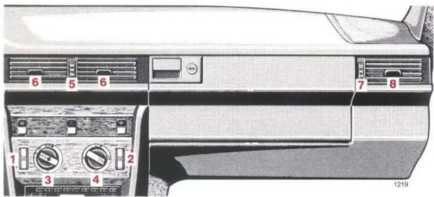
6 5 6 7 8 1 2 3 4 1219Heating and Ventilation
1 Temperature selector for heater, left vehicle side (°C)
2 Temperature selector for heater, right vehicle side (°C)
Using the temperature selectors, the heater can be set separately for each vehicle side and is continuously variable between the two final positions "MIN" and "MAX".
A basic setting of 22 °C is recommended for both temperature selectors.
Should the passenger compartment require to be heated, the set temperature will be attained very quickly and is then kept at this level. Should the set inside air temperature be exceeded due to solar radiation or high external temperatures, only non-heated fresh air will be supplied to the inside.
3 Air volume control knob Switch on by turning clockwise. The air volume is then increased gradually as the switch is turned towards the stop. The 4-speed blower cuts in as of scale mark "I".
To control the interior temperature properly, the air volume control knob should be turned to blower speed "II", or at least to blower speed "I".
In case of annoyance due to dust and fumes from outside, the air supply to the vehicle interior can be shut off (turn air volume switch anti-clockwise to the stop). When driving, select this setting only briefly.
4 Air distribution switch (12 notches)
Air to windscreen
Air to windscreen as well as to driver's and rear compartment footwells
Air to driver's and rear compartment footwells
Air is emitted from swivelling air outlets 6 and 8 only
5 Thumbwheel for nonheated fresh air, infinite adjustment Turn wheel up = open
6 Swivelling air outlets for non-heated fresh air
7 Thumbwheel for side ventilation, infinitely variable adjustment (left and right vehicle sides) Turn wheel upwards = open
8 Swivelling air outlet for side ventilation (LH and RH vehicle sides)
Fresh air enters the vehicle through the opening in front of the wind-screen (keep free of snow) and leaves the vehicle through the inside ventilation openings below the rear window if the windows are closed. Do not cover the ventilation openings with clothes etc..
Examples for Heating and Ventilation Settings
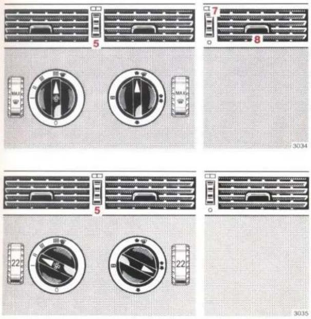
Maximum volume of air heated to maximum temperature channelled to the windscreen. To defrost the side windows, turn thumbwheels 7 of the side ventilation up and point swivelling air outlets 8 towards the side windows. Turn thumbwheel 5 all the way down.
A medium volume of heated air (controlled) is channelled to the windscreen and to the footwell. Turn thumbwheel 5 all the way down.
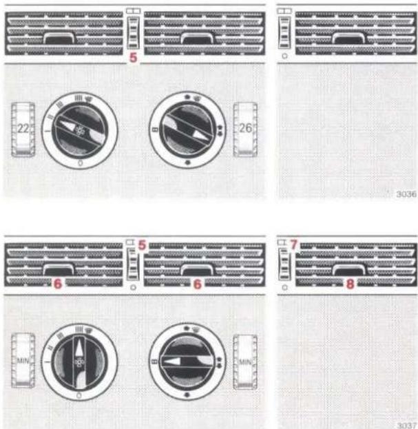
Medium volume of heated air (LH and RH sides separately controlled) channelled to windscreen and footwell. Turn thumbwheel 5 all the way down.
Maximum volume of nonheated air emitted from swivelling air outlets 6 and 8 only. For this purpose, turn thumbwheels 5 and 7 all the way up.
Supplementary Heater
Do not start the supplementary heater at petrol stations and in confined spaces (e.g. garages).
The supplementary heater can be operated together with the vehicle heater independently of the engine. It serves to heat the passenger compartment and to defrost the vehicle windows.
The supplementary heater will also preheat the engine coolant. This will facilitate the engine starting process at very low ambient temperatures.
The supplementary heater can also be switched on while driving if the vehicle heater is not yet generating enough heat.
In order to conserve battery power, only run the supplementary heater as long as necessary when the engine is stopped and do not keep switching the supplementary heater on and off.
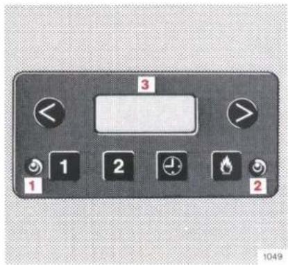
1 Indicator lamp (yellow) Preselector engaged
2 Indicator lamp (green) Supplementary heater in operation
3 Display window for time of day and cut-in time
text_image
3 1 2 2 1 2 2 10491 Programmed heating 1st preselected cut-in time
2 Programmed heating
2nd preselected cut-in time
Calling up time of day
Immediate heating
< Time of day and cut-in time adjustment (reverse)
Time of day and cut-in time adjustment (forward)
The supplementary heater can be switched on immediately (immediate heating) or can be programmed to switch itself on automatically (programmed heating) at the desired time.
Prior to switching on the supplementary heater, pay attention to the adjustment of heating and ventilation:
- Do not set air distribution switch to position ☐☐.
- Set air volume switch at least to blower speed "I". A higher blower speed will better heat the passenger compartment, but the load on the battery will also be higher.
- Set temperature selectors of the vehicle heater to the desired in-car temperature. The in-car temperature automatically adjusts to the set level, e.g. 22 °C.
- On vehicles with automatic climate control one of the buttons of the automatic climate control system must be pressed (except for button 0).

Calling and Adjusting Time of Day
Push and hold down button 📋. The time of day is displayed in window 3.
If the time of day is to be corrected, push button ⏻ and button ◀ or ▶ at the same time. Brief actuation will cause a 1 minute adjustment.
Setting of Cut-in Time for Programmed Heating
Two cut-in times can be programmed (one each on buttons 1 and 2).
Press button 1 or 2. Yellow indicator lamp 1 comes on. The number of the button pushed and the cut-in time programmed on this button will be displayed in window 3 for 20 seconds. As long as the cut-in time is displayed it can be adjusted. For this purpose, push button < or >.
Switching on Programmed Heating
Press button 1 or 2. Yellow indicator lamp 1 comes on. The time displayed in window 3 will indicate when the supplementary heater starts heating.
As soon as the supplementary heater is operating, yellow indicator lamp 1 goes out and indicator lamp 2 comes on.
Maximum operating time of the supplementary heater is 60 minutes.
Switching on Immediate Heating
Push button ⚙. Green indicator lamp 2 comes on. The supplementary heater will start after approx. 30 seconds.
Maximum operating time of the supplementary heater is 60 minutes.
Switching Off
Green indicator lamp 2 is on: push button 🔒. Green indicator lamp goes out.
Yellow indicator lamp 1 is on: push button 1 or 2 (number appears in display window). Yellow indicator lamp goes out.
After a maximum period of 60 minutes the supplementary heater will cut out automatically. The green indicator lamp goes out.
Notes:
If the supplementary heater is switched on and the key removed from the steering lock or turned to position 0 or 1, the blower will cut in only after a certain coolant temperature has been attained.
If the operating voltage has been interrupted, the time display in window 3 will flash. If this happens, first reset the time of day and then the cut-in time of the supplementary heater.
If green indicator lamp 2 goes out again after the supplementary heater has been switched on, this indicates a fault. Should this fault occur once more, consult a MERCEDES-BENZ service station.
In order to ensure the operational reliability of the supplementary heater at all times, it is necessary to operate it throughout the year, i.e. at least once a month for approx. 5 minutes.
text_image
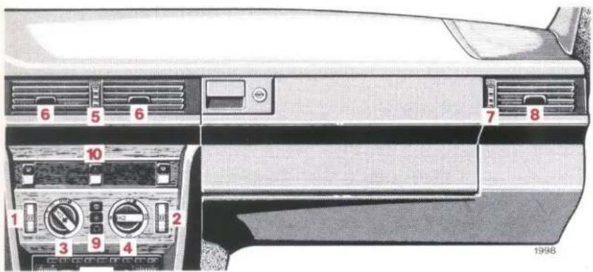
6 5 6 7 8 10 1 2 3 9 4 1998Air Conditioning
The air conditioning system operates only when the engine is running. High engine speeds produce a high refrigerant compressor speed and thus increased cooling.
To ensure proper functioning of the air conditioning system and the recirculating-air cooling mode, air volume switch 3 must be set at least to blower speed "I". A higher blower speed must be selected if an increased cooling effect is desired.
Even with the air conditioning system switched on the automatic vehicle heater controls the inside temperature in compliance with the setting of temperature selectors 1 and 2.
The air can be distributed individually by means of air distribution switch 4 and swivelling outlets 6 and 8. Use thumbwheels 5 and 7 to control the air volume. Nonheated air is emitted from swivelling outlets 6.
9 Buttons

Continuous operation

Normal setting

Recirculating air
Switching on: press button – the indicator lamp in the pushed button comes on.
Switching off: press the pushed button once again – the indicator light goes out.
Button

pressed:
Humidity is extracted from the air in order that misting on the inside of the windows is very quickly cleared.
Button

pressed:
Depending on the requirement, the system will heat or cool. The air conditioner will cut in only if the set interior temperature is exceeded. A basic setting of 22^ C is recommended for both temperature selectors.
Button pressed:
If the ambient temperature exceeds approx. 15 °C the system will change over from recirculating-air operation to fresh-air operation after 30 minutes automatically. If the ambient temperature is less than approx. 15 °C, it will change over after 5 minutes.
Continuous recirculating-air cooling is possible if the ambient temperature exceeds 20 °C. For this purpose, button ☑ or button ☑ must be pressed and both temperature selectors must be engaged in the "MIN" position.
Recirculating-air cooling may be switched on if unwanted odors or dust enter the vehicle from outside.
Switch off recirculating air mode if the windows mist up on the inside.
Rapid cooling:
- Do not set temperature selector wheels 1 and 2 to temperatures above 20^ .
- Press button 📄 or ✱
- Turn air volume switch 3 clockwise to the stop.
- Turn air distribution switch 4 to symbol ☐☐.
- Turn thumbwheels 5 and 7 all the way up.
- Close side windows and pop-up/sliding roof completely. Hot inside air may first be evacuated by driving for a short while with all the side windows down and the pop-up/sliding roof opened.
Mist on outside of windscreen:
In damp weather the outside of the windscreen can mist up. In this case, change position of air distribution switch 4 so as to have less cooled air channelled to the windscreen.
Note:
It is normal for water to drain through the vehicle underside. This is condensation from the air conditioning system.
text_image
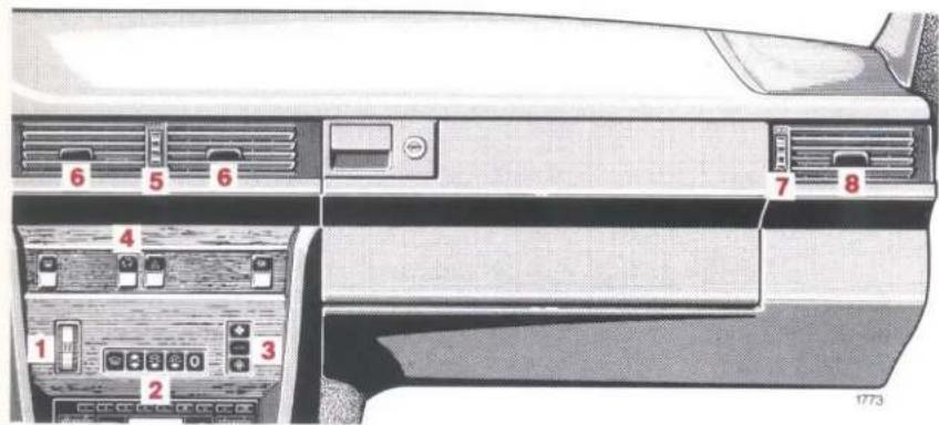
6 5 6 7 8 4 1 3 2 1773Automatic Climate Control
The automatic climate control is operational only when the engine is running.
1 Temperature selector
2 Function selector buttons

Defrosting

Air up or down

Normal setting

Economy position

Off (no air supplied)
3 Air volume setting buttons

Maximum air volume

Automatically controlled air volume

Minimum air volume
4 Recirculating air switch
5 Thumbwheel for air outlets 6
6 Swivelling air outlets
7 Thumbwheel for air outlet 8 (left and right vehicle sides)
8 Swivelling air outlets (left and right vehicle sides)
Heating, cooling and air distribution inside the vehicle (top, center, bottom) are controlled automatically.
Air outlets 6 and 8 can be swivelled as required. Air volume is controlled by means of thumbwheels 5 and 7.
Turn thumbwheel downwards = closed
When the vehicle exterior lamps are switched on (standing lamps excepted), the symbols in the buttons are lighted. The symbols of the pushed buttons shine more brightly.
Notes:
The automatic climate control will function properly only if windows and pop-up/sliding roof are closed.
Not all of the air outlets 6 and 8 must be closed.
It is normal for water to drain through the vehicle underside. This is condensation from the automatic climate control.


Temperature Selection (°C)
The desired temperature can be set with the temperature selector. This temperature is attained as quickly as possible and then maintained continuously. We recommend a basic setting of 22 °C.
Temperature selector engaged in final ion "MIN" = full cooling power, ion "MAX" = full heating power.
With final position "MIN" or "MAX" engaged and butpressed a large volume of air is supplied inuously.

Recirculating Air Cooling Mode
Press switch upper end = recirculating air mode selected. The indicator lamp in the switch comes on.
Recirculation-air cooling may be switched on if unwanted odors or dust enter the vehicle from out-
side.
At high outside temperatures the automatic climate control changes over from outside air to recirculating air automatically. Thus the air is cooled down faster.
If the ambient temperature exceeds approx. 7 °C the system will change over from recirculating-air operation to fresh-air operation after 30 minutes automatically. If the ambient temperature is less than approx. 7 °C, it will change over after 5 minutes.
Continuous recirculating-air cooling is possible if the ambient temperature exceeds 20 °C. For this purpose, button 🎨 or button ✉ must be pressed and both temperature selectors must be engaged in the
Switch off recirculating air mode if the windows mist up on the inside.
Note:
Recirculating air mode cannot be selected if button 📁 or 0 is pressed.
text_image
8 6 6 8 1222
Normal setting - cooling

Economy setting – ventilation
text_image
8 6 6 8 1223
Normal setting - heating

Economy setting – heating
Selection of Functions

Normal setting
Depending on the outside temperature and the set inside temperature the system cools or heats automatically.
In the cooling mode air is channelled to air outlets 6 and 8 only.
During the heating mode hot air is mainly channelled to the footwell.
In the heating mode air is periodically emitted from air outlets 6.
No more air is supplied to the windshield and the side windows than is required to prevent them from being misted up under normal weather conditions.
At low outside temperatures no air is supplied until the coolant has been slightly warmed up.

EC (ECONOMY) = economy setting
This function corresponds to the normal setting, but there is no cooling (thus saving fuel).
text_image
8 6 6 8 1224
Air up and down - cooling
text_image
8 6 6 8 1225
Air up and down - heating

Air is blown up and down
Select this function if the windshield mists or freezes up on the inside or if a lot of wet snow falls. Later on the system can be changed over to 🧑 or 🧑 again.
In the heating mode air is channelled to the wind-screen, to the footwells and to the side windows. Air is emitted periodically from air outlets 6.
In the cooling mode air is emitted from all air outlets.
text_image
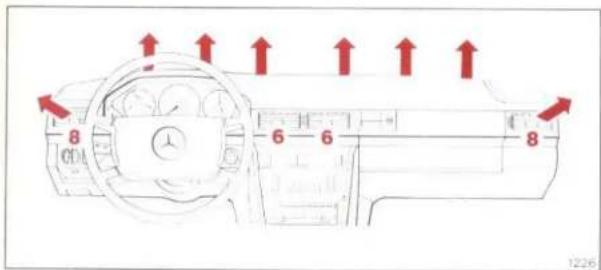
8 6 6 8 1226
Defrosting

Defrosting
Independent of the position of the temperature selector and the air volume setting, a large volume of air heated to maximum temperature is always channelled to the windscreen and air outlets 8.

Off
Air supply and heating are switched off. Select this function only for brief periods while driving.

text_image
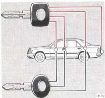
Diagram showing car ownership or repair process with keys and a car, labeled with number 1139Vehicle Keys
Together with the vehicle you are handed over two main keys, one secondary key and one flat key.
Main Key – square headed – fits all locks on the vehicle.
Secondary key – rounded head – fits only the locks of driver's and front passenger's doors, steering lock and filler flap. The secondary key does not fit the locks of boot, glove box or oddments box.
Flat Key
The flat key fits all vehicle locks. We recommend that you carry the flat key with you and keep it in a safe place so that it is always handy, if needed (e.g. in your wallet). Never leave the flat key in the vehicle.
Obtaining Replacement Keys
Your vehicle is provided with a special lock system. Replacement keys can therefore only be obtained via MERCEDES-BENZ service stations. If the keys are lost, assistance is rather time-consuming.
text_image
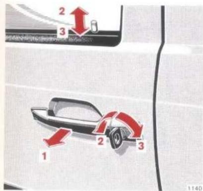
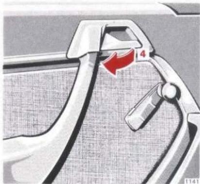
1 2 3 1140Opening the Doors
From outside: swing handle (1) outwards.
From inside: pull handle (4) in door panel inwards.
Locking and Unlocking of Doors
From outside: turn key.
From inside: to lock, push down safety plunger; to unlock, pull handle in door trim panel.
2 Unlocking
3 Locking
natural_image
Close-up of a car's seatbelt with a red arrow pointing to the handle (no text or symbols visible)One cannot lock:
- The driver's door if it is open.
● Each door if the door lock has not engaged fully. In this case open the door and shut it again.
text_image
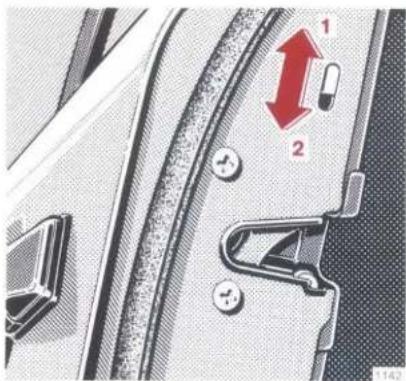
Diagram of car seatbelt mechanism with numbered parts and directional arrows indicating movement or changeChildproof Lock (Rear Doors)
Actuate safety catch (e. g. with the vehicle key):
1 Unlocked
2 Locked. When closed, the doors can no longer be opened from inside. The unlocked doors can be opened from outside (plunger up).

Central Interlock System
The central interlock system of a vehicle can be locked or unlocked at the driver's door, at the front passenger door or at the boot lid (boot lid with main key only). The central interlock system includes all doors, the boot lid and the filler flap.
Doors
When locking the system the lock plungers of all doors must sink in completely. If this is not the case the lock of the respective door has not engaged fully. Open the door once more, press down the lock plunger and close the door correctly.
The childproof locks of the rear doors are not affected by the central interlock system.
The central interlock system can be locked from inside by pressing in the lock plunger of the driver's door or front passenger door. To lock, the driver's door must however be closed. The central interlock system can be locked at the front passenger door only when the steering lock key is withdrawn or if the key is slipped in again after withdrawal but is not turned (key in steering lock position 0).
Is a vehicle locked with the central interlock system the rear doors can also be unlocked individually from inside. To lock the door, press in the lock plunger again.
Boot lid
To unlock the central interlock system, turn main key anti-clockwise to the stop and then reverse to its initial position. Press in boot lock push button and open lid.
To lock the central interlock system, turn main key clockwise to the stop and reverse to its initial position.
The boot lid can also be locked separately (e.g. when the vehicle is left in a workshop with the secondary key only). For this purpose, turn main key clockwise to the stop and withdraw. In this case the boot lid can only be unlocked with the main key which must be inserted and turned to the left.
Important!
If the boot lid is unlocked in a vehicle equipped with a central interlock system the doors and the filler flap will also be unlocked. After closing the boot lid, the vehicle must be locked again with the central interlock system.
Note:
If the filler flap cannot be opened, refer to "Emergency Release of Fuel Filler Flap" (page 100).
text_image
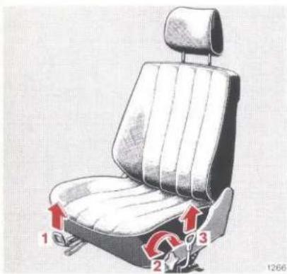
1 2 3 1266Manual Front Seat Adjustment
Longitudinal direction: Pull up handle (1); slide seat forward or rearward and allow handle to engage.
Inclination of seat cushion: Turn handwheel (2) forward or rearward.
Height of seat: Pull up handle (3); push seat forward to raise it, push seat rearward to lower it, allow handle to engage.
Inclination of seat back: Turn handwheel (4) forward or rearward (up to resting position).
natural_image
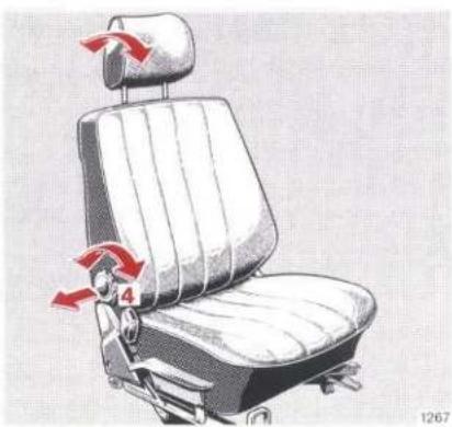
Illustration of a car seat with red arrows indicating force or motion, no text or symbols presentHeight of safety headrest: Pull handwheel (4) out and turn forward or rearward. Following adjustment push handwheel in again.
Inclination of safety headrest: The inclination can be manually adjusted.
Notes:
Adjust the headrest to support the back of the head at approximately ear level. In doing so, the headrest must not be pulled beyond the uppermost possible stop achievable with the handwheel (4).
To remove headrest refer to "Practical Tips", page 97.
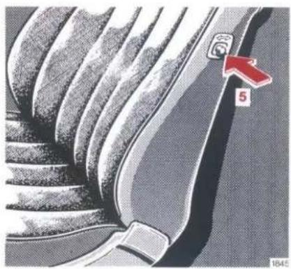
natural_image
Close-up of a car's seatbelt with a red arrow pointing to the number 5 (no text or symbols on the suit itself)Coupé: When the doors are closed and the engine is running the seat backs are locked in position. Press release button (5) to release the lock when the doors are closed. If one door is open, the backrests are not locked.

text_image
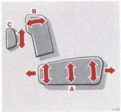
C B A 1039Electrical Front Seat Adjustment
The switches are located in the front doors.
Turn key in steering lock to position 1 or 2 (if one of the front doors is opened, adjustments are possible even with the key withdrawn or in position 0).
Adjusting seat and safety headrest:
A Adjustment of seat cushion.
B Adjustment of seat back.
C Adjustment of headrest.
Adjust headrest to support the back of the head approximately at ear level. The headrest can also be tilted forward by hand.
Note:
Do not pull the headrest beyond the locking position by hand.
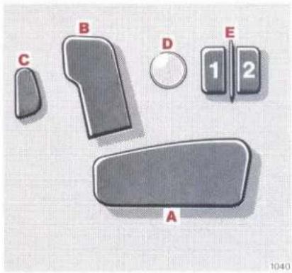
Storing positions of seats and safety headrests:
D Memory button.
E Position buttons "1" and "2".
Two positions can be stored. First adjust seat and headrest, then push memory button D, release and push position "1" button within 3 seconds. Another seat and head-rest position can be stored with position "2" button.
text_image
B C D E 1 2 A 1040Calling stored seat and safety headrest positions:
If a stored position is desired, push corresponding position button ("1" or "2") until seat and headrest adjustment is completed. As soon as the position button is released, the adjusting process is interrupted immediately for safety reasons.
For the detachment of headrests, refer to "Practical Tips", page 97.
natural_image
Top-down architectural sketch of a vehicle interior with numbered components, surrounded by textured ground and road (no text or symbols)Orthopaedic Backrest
There are two air cushions in the backrest for supporting the spine. The degree of backrest curvature and the position of the bulges can be adjusted in steering lock position 1 or 2.
By means of pressure selector (1), the pressure in the air cushions can be infinitely varied between positions "0" = pressureless and "4" = full pressure.
Using height selector (2), the height of the backrest curvature can be set in five positions between position "A" = lowest support and "E" = highest support.
After a journey has been interrupted, the backrest curvature which was last selected is automatically reset.

text_image
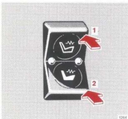
Diagram of a switch with labeled parts and directional arrows indicating movement or changeSeat Heater
Turn key in steering lock to position 1 or 2.
Switching on:
Press symbol 1 = normal heating. The indicator lamp in the switch comes on.
Press symbol 2 = rapid heating. Both indicator lamps in the switch come on.
After approx. 5 minutes the seat heater automatically switches to normal heating operation and only one indicator lamp in the switch remains on.
Switching off:
If one indicator lamp in the switch comes on, push symbol 1.
If both indicator lamps in the switch come on, push symbol 2.
The seat heater is cut out automatically after approx. 30 minutes.
Notes:
The seat heater has a high power consumption. For this reason, do not leave the seat heater switched on longer than needed.
If many power consuming units are switched on or if the battery is insufficiently charged, the seat heater may cut out. In this case the indicator lamp in the switch starts flashing (during the fast heating mode both indicator lamps flash). As soon as sufficient voltage is available again the seat heater cuts in automatically.
If the flashing indicator lamps are disturbing the seat heater can be switched off by means of the switch.
natural_image
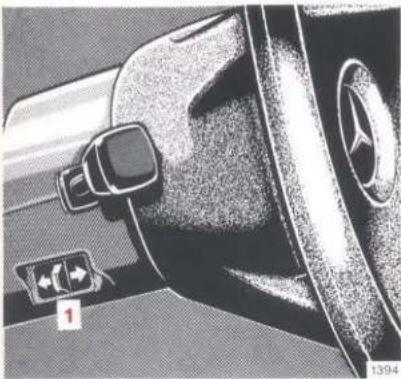
Close-up of a car's front wheel and side door, showing dashboard and rearview components (no visible text or symbols)Electric Steering Column Adjustment System
Turn key in steering lock to position 1 or 2 (if one of the front doors is opened, key may also be withdrawn or in position 0).
To adjust the steering column, actuate switch (1).
Note:
If the vehicle is equipped with an electric driver's seat adjustment system and memory, the steering column position is also stored in the memory together with seat and headrest positions.
text_image
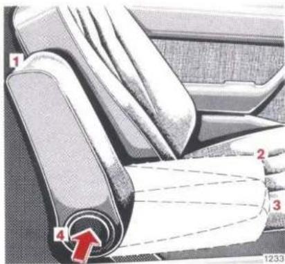
1 2 3 4 1233Armrest (Front Seats)
Position 1 = armrest folded up.
Position 2 = for normally inclined seat back.
Position 3 = for extremely inclined seat back.
To fold down armrest, press locking button (4).
Note:
The armrest does not suffice as a child restraint system. In the case of a frontal collision a child can be catapulted forward over the locked armrest. It is only suitable as protection against objects which might slip forward when the vehicle is braked.

natural_image
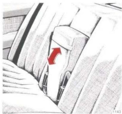
Illustration of a car seatbelt with a red arrow indicating clockwise motion (no text or symbols)Armrest (Rear Seat)
Pull armrest down using the loop.
Saloon: At the same time the belt buckles of the outer seats swing out.
Coupé: The cushion between the rear seats can be removed from the oddments tray.
For removal of rear seat cushion refer to "Practical Tips", page 98.
natural_image
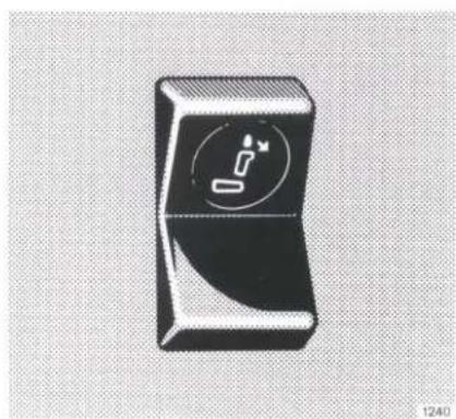
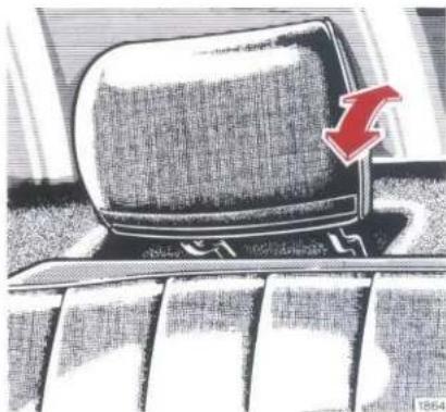
Black rectangular device with a circular icon containing a white plug symbol, placed on a textured background (no text or labels visible)Rear Seat Headrests
Fold down headrests (with engine idling):
Depress top of switch (symbol) = the upright headrests fold down.
Erecting headrests:
Using the handle strip, raise head-rest until it engages.
natural_image
Illustration of a computer monitor on a keyboard with a red arrow pointing to it, no text or symbols present.Inclination of the headrests:
The inclination can be adjusted by hand.
Note:
If the rear seats are occupied we recommend setting up the head-rests for safety reasons.
Restraint System — Seat Belts, Seat Belt Tensioners, Airbag
Legislation in many countries specifies the use of seat belts. Required or not, all passengers on front and rear seats should always fasten their seat belts.
Of course, this also applies to vehicles equipped with airbag as this system can perform its intended function only if the passengers have fastened their seat belts.
Notes:
Each individual seat belt is intended to be used by a single person only. The seat belts are not intended to be used by persons shorter than approx. 140 cm (in particular children). They must ride only in suitable restraint systems on the rear seats.
Child restraint systems recommended by us can be attached to the seat belts installed. Any MERCEDES-BENZ service station will gladly advise you accordingly.
For cleaning and care of belt webbing, see page 96.
For safety regulations for seat belts, seat belt tensioners and airbag, refer to page 47.
natural_image
Interior view of a car showing a vehicle's rearview and side profile with directional arrows (no text or symbols)Seat Belt Warning Lamp
The seat belt warning lamp is to remind the passengers that the seat belts should be fastened before driving off. After flashing for a short while it will go out automatically.
text_image
Diagram of car seatbelt mechanism with numbered parts and directional arrows indicating movement or forceSeat Belts
Each seat of the vehicle is equipped with a seat belt, and the front seats are in addition provided with seat belt tensioners attached to the seat belt inertia reels.
text_image
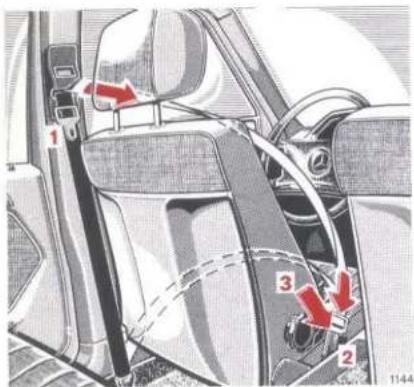
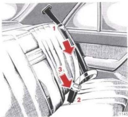
1 2 3 1145Fastening Seat Belts
Saloon:
Pull belt by tongue (1) over shoulder and lap so that the lap belt is in front of the hips. The belt must not be twisted. Sitting positions which could adversely affect the correct fit of the seat belt must be avoided for safety reasons.
Press tongue (1) into buckle (2) and allow to engage audibly.

text_image
4 1146Adjust front seat belts so that the upper belt passes over the center of the shoulder. For this purpose, push button (4) and raise or lower the belt outlet (3 positions).
The seat belt must be tight. Check if it is tight immediately after having fastened it and regularly while driving. If necessary, tighten lap belt by pulling the upper belt section upwards.
natural_image
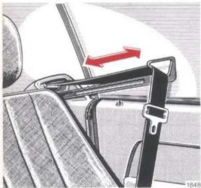
Close-up of a car seatbelt buckle with red directional arrow indicating compression (no text or symbols)Coupé:
The belt hand-over arm carries the belt forward when the respective door is closed and the key in the steering lock is turned to position 2.
The belt hand-over arm returns to its initial position as soon as the safety belt tongue engages with the lock.
If the seat belt is not fastened within approx. 30 seconds, the belt hand-over arm returns to its initial position.
This also happens if the door is opened or the key in the steering lock is returned to 1 or 0 position.
Pull belt by tongue (1) over shoulder and lap so that the lap belt is in front of the hips. The belt must not be twisted. Sitting positions which could adversely affect the correct fit of the seat belt must be avoided for safety reasons.
Press tongue (1) into buckle (2) and allow to engage audibly.
The seat belt must be tight. Check if it is tight immediately after having fastened it and regularly while driving. If necessary, tighten lap belt by pulling the upper belt section upwards.
When fastening the seat belt the swivelling bracket at the lower belt anchoring point must point forward.
When the belt feeder is in the initial position, the swivelling bracket points rearward.
text_image
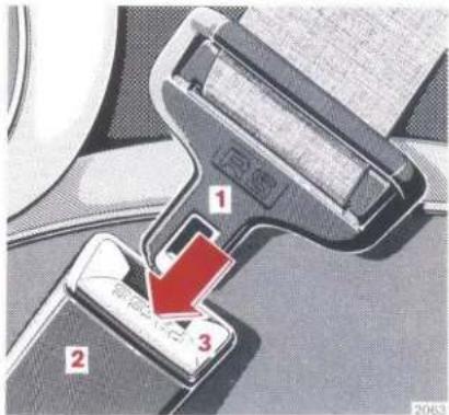
1 2 3 2063Unfastening the Seat Belts
Push button (3) in buckle.
Return tongue (1) to initial position.
Operation
The inertia reel of the seat belt stops the belt unwinding further in case of vehicle deceleration in any direction and if the belt is pulled out quickly.
The locking function of the inertia reel can be checked by pulling the belt out quickly.

text_image
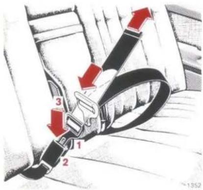
Diagram of a car seatbelt buckle with numbered parts and red directional arrows indicating movement or force.Lap Belt in Rear Compartment
Pull belt by tongue (1) over the lap so that it lies in front of the hips. Press tongue (1) into buckle (2) until it clicks into place. The belt must not be twisted, but it must fit snugly. Sitting positions which could adversely affect the correct fit of the seat belt must be avoided for safety reasons.
To shorten the belt, pull belt end with the tongue engaged. To lengthen the belt, turn the tongue so that it is at a little more than 90° to the belt and pull before fastening the belt.
To unfasten the belt, press button (3) in buckle.
If the center seat is not occupied, the belt buckle and the wound up belt can be pushed into the recesses below the rear seat back-rest (to the left and right of the armrest).
natural_image
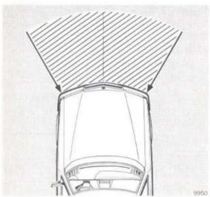
Top-down line drawing of a car's front wheel and roof structure (no text or symbols)Seat Belt Tensioners
The seat belt tensioners are attached to the inertia reels of the seat belts and are operational when the steering lock key is in position 1 or 2.
The seat belt tensioners are so designed as to be activated only in case of severe head-on collisions. They then tighten the belts around the body so that it can move forward as little as possible.
The seat belt tensioners will not be activated in minor frontal impacts, in case of rollovers, side and rear end collisions as well as in accidents during which no substantial frontal forces are exerted. Like the other passengers, driver and front passenger will then be protected by the fastened seat belts in the usual manner.

text_image
Diagram of car interior showing seat, steering wheel, and driver's seat with numbered components and directional arrows indicating motion or movement.3006
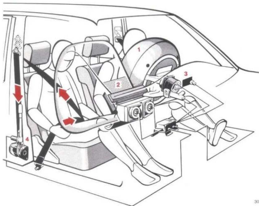
Airbag
The driver's airbag (1) is accommodated under the padded boss of the steering wheel. It can be identified by the lettering "SRS-AIRBAG" on the padded boss.
The front passenger's airbag (2) is accommodated in the dash panel in place of the glove box. It can be identified by the lettering "SRS-AIRBAG" on the airbag covering.
Combined with the fastened seat belts and the integrated seat belt tensioners (4) driver's and front passenger's airbags provide improved protection for the driver and the front passenger.
The operational readiness of the restraint system (airbag) is indicated by the "SRS" indicator lamp (3) in the instrument cluster. If the key in the steering lock is turned to position 1 or 2, the indicator lamp comes on for approx. 4 seconds. If it fails to come on or go out or if it flickers or comes on while driving there is a fault in the system. The restraint system ("SRS"), however, is not activated by this fault. We nevertheless recommend you in such a case to consult a MERCEDES-BENZ service station without delay and have the "SRS" inspected. Otherwise there arises the danger of the "SRS" not being activated during an accident.
The airbag is so designed as to be activated only in severe head-on collisions (see illustration on page 45). Its protective function becomes effective only in such accidents.
Driver and front passenger must have fastened their belts as otherwise the airbags cannot provide the intended protection.
In vehicles provided with an airbag for the front passenger all persons shorter than 140 cm may ride in the vehicle only in suitable restraint systems on the rear seats.
The airbags will not be activated in minor head-on collisions, in rollovers or side and rear end collisions or in accidents during which no substantial frontal forces arise. The passengers will then be protected by the fastened seat belts in the usual manner.
During the activation of the "SRS" a small amount of smoke will briefly be released. This smoke, however, is neither injurious to health nor does it indicate a fire in the vehicle.
The service life of present design airbags extends to the date quoted on the sticker in the frame of the driver's door.
In order to ensure continued reliability of the system after that date, consult a MERCEDES-BENZ service station.
Safety Instructions for Restraint System – Seat Belts, Seat Belt Tensioners, Airbag
Seat belts which have suffered damage or which have been subjected to high tensile stress during an accident must be replaced. In addition to this the belt anchors must be inspected. Only use safety belts recommended by us.
The belt webbing must not be routed via sharp edges.
No modifications to the belt are authorized which affect its efficiency.
Replace airbags and seat belt tensioners which have been activated during an accident.
No modifications must be made to the component parts or the wiring of the "SRS".
This applies particularly to the fitting of additional coverings on the steering wheel padded boss and the cover of the front passenger airbag or to the attachment of badges thereon.
If untrained personnel is working on the "SRS" or the unit is installed/removed incorrectly, this may cause an uncontrolled activation of the airbag and seat belt tensioners and consequential injury. Furthermore, incorrect work may render the "SRS" inoperative. For this reason the "SRS" may only be worked on at MERCEDES-BENZ service stations.
When scrapping the airbag and the seat belt tensioners, be sure to follow the safety instructions we have drawn up for this purpose. These instructions are available at every MERCEDES-BENZ service station.
When a vehicle is sold, the seller is obliged to notify the buyer on this subject. This is done by handing over the Owner's Manual.
text_image
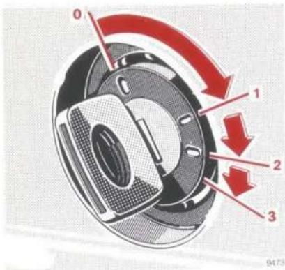
0 1 2 3 9473Steering Lock
0 Steering is locked when the key is withdrawn and the steering lock is engaged. The key can be withdrawn only in zero position.
1 Steering is unlocked.
(If necessary, move steering wheel slightly to turn the key clockwise to position 1.)
2 Driving position.
3 Starting position.
Starting and stopping the engine, refer to page 14.
Notes:
Do not remove the key while the vehicle is still rolling as the car can then no longer be steered.
After removing the key, turn steering wheel slightly if required so that the steering lock can engage.
The following consuming units can be operated with the key in steering lock position 1:
Wiper,
windscreen washer, headlamp cleaning system (only with lighting switch positions ≡0.0= and ≡D),
headlamp flasher, cigar lighter, glove box lamp, radio,
pop-up/sliding roof, heated rear window, window lifts,
front seat adjustment, seat heater,
orthopaedic backrest, steering column adjustment system.
Power generation is limited at idle speed.
For slow bumper-to-bumper driving we therefore recommend shutting off as many as possible of the power consuming units. This measure prevents excessive current from being drawn from the battery.
It is very effective to switch off the following consuming units, e.g.: Seat heater, heated rear window. Moreover, the air volume switch should be moved to blower speed "I".
text_image
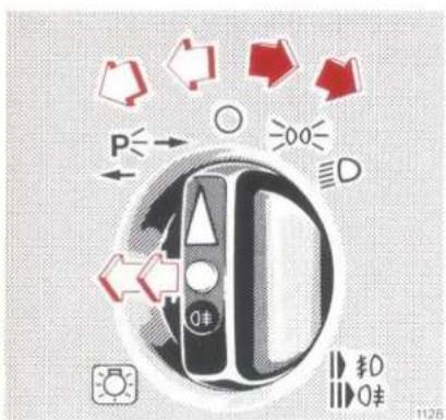
P←→ 000 D 1分 0 0分 1126Lighting Switch ^1


Off

Parking lamps (includes number plate and instrument lamps)

Dipped beam Main beam (combination switch pressed forward)
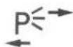
Standing lamps, right (turn left to 1st notch) Standing lamps, left (turn left to 2nd notch)

Fog lamps (pull to 1st notch) In addition to parking lamps, dipped or main beam

Rear fog lamp (pull to 2nd notch) In addition to fog lamps. The indicator lamp in the lighting switch comes on.
Note:
With the steering lock key withdrawn and one of the front doors opened a signal will sound if the vehicle exterior lighting (except for standing light) is left on.
^1 Deviations may occur in individual countries because of the legal requirements.

natural_image
Close-up of a metallic connector with ribbed internal structure and a small indicator symbol above (no text or labels)Headlamp Beam Control
Vehicles without Level Control
Setting examples:
"0" Driver's seat or driver's and front passenger's seats occupied
"1" Driver's seat, front passenger's seat and rear seat bench occupied
"2" Driver's seat occupied and maximum load in the boot
"3" Driver's seat, front passenger's seat and rear seat bench occupied and a load in the boot (observe permissible rear axle load)
Possibly required for trailer operation
Vehicle Equipped with Level Control
Setting examples:
"0" Driver's seat or driver's and front passenger's seats occupied
Driver's seat, front passenger's seat and rear seat bench occupied
Driver's seat, front passenger's seat, and rear seat bench occupied plus a load in the boot (observe permissible rear axle load)
"1" Driver's seat occupied and maximum load in the boot
Possibly required for trailer operation
Positions "2" and "3" not required.
text_image
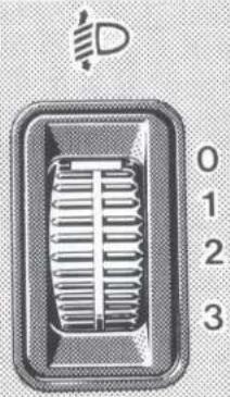
4 4 1 2 3 5 5 9677Combination Switch ^1
1 Dipped beam (lighting switch position ≡D)
2 Main beam (lighting switch position ≡D)
3 Headlamp flasher (main beam available independent of lighting switch position)
4 Turn signals, right
5 Turn signals, left
To operate the turn signals, engage combination switch. The switch is automatically reset when the steering wheel is turned through a fairly large distance.

text_image
6 7 9684To signal minor changes in the vehicle's direction, press combination switch to the point of resistance only and hold it there.
6 Control for
● windscreen washer system
- headlamp cleaning system (will work only with lighting switch in position 20 or D) When in operation, the wiper is also activated.
The windshield washer reservoir, the hoses and the nozzles of the windshield washer system are heated automatically.
7 Windscreen wiper control
0 Windscreen wiper switched off
I Intermittent wiping
II Normal wiping
III Fast wiping
Notes:
If a turn signal fails on the vehicle or on the trailer, the turn signal indicator flashes and ticks more frequently than usual. In addition, the bulb failure indicator lamp lights up.
When the windscreen wiper is in operation streaks may be formed on the windscreen. In this case, actuate windscreen washer, even when it is raining. Adhering to the correct mixing ratio, always add the appropriate MB windscreen washing detergent S for summer or W for winter to the water in the windscreen washer reservoir.
natural_image
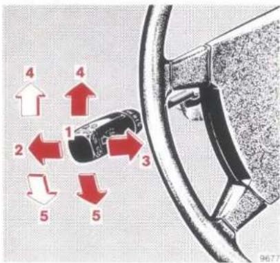
Interior view of a car showing the front and side panels with numbered labels (1, 2), no readable text or symbols beyond labels.Exterior Mirrors
At low ambient temperatures the exterior mirrors are heated automatically.
Driver's side:
Exterior mirror (2) can be adjusted from inside the vehicle by means of adjusting lever (1).
natural_image
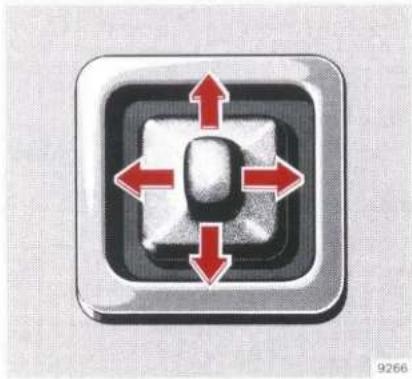
Close-up of a black square button with four red arrows pointing outward from the center, no text or symbols present.Front passenger's side:
Move key in steering lock to position 2. The exterior mirror can be adjusted by means of the lever.
Note:
If the mirror has been forcibly removed from its safety catch (e.g. in a car wash), it must be repositioned by applying firm pressure.
natural_image
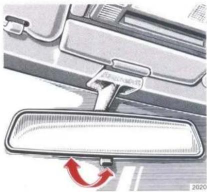
Interior view of a car dashboard with a red curved arrow indicating rotation (no text or symbols)Inside Rear View Mirror
The mirror can be tilted to the anti-dazzle position by means of the lever at its lower edge.
natural_image
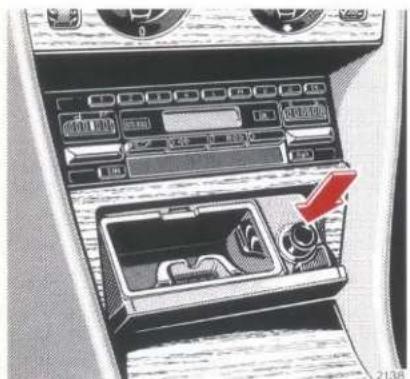
Interior view of a car infotainment system showing dashboard, air intake manifold, and control panel (no readable text or symbols)Cigar Lighter
Key in steering lock position 1 or 2.
Tap cover plate. The ashtray is opened automatically.
Press in cigar lighter; it will pop out automatically when hot.
natural_image
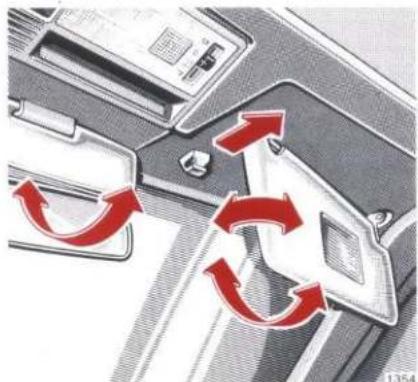
Diagram showing red curved arrows indicating rotational or directional motion around a device component (no text or symbols)Sun Visors
Swivel sun visors downward as a protection against glare.
If glare is caused by the side window, disengage outer sun visor from bearing at inside and swivel sideways. In this position the sun visor with illuminated mirror can also be adjusted lengthwise.
natural_image
Close-up of a car interior panel with a red arrow indicating clockwise motion (no text or symbols)Sun visors with illuminated mirror:
When the cover is opened, the illumination is switched on. In such a case, the sun visor must be engaged in inner bearing.

natural_image
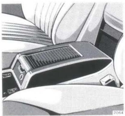
Illustration of a car interior with a solar panel and control panel (no text or symbols)Oddments Box
Vehicles equipped with front passenger airbag
A lockable oddments box is mounted on the center console in place of the glove box in the dash.
natural_image
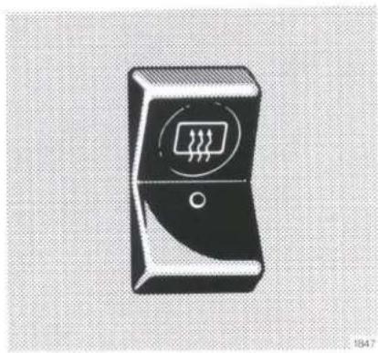
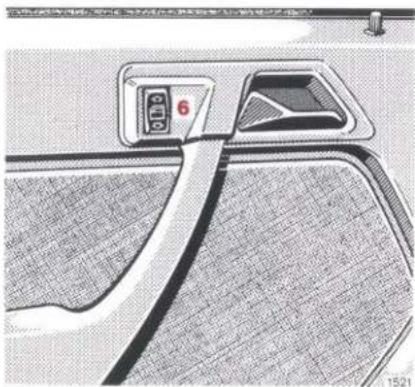
Black-and-white illustration of a rectangular electronic device with a circular sensor or circuit symbol on its side (no text or labels)Heated Rear Window
Turn key in steering lock to position 1 or 2.
When the rear window heater is on, the white indicator lamp in the switch lights up.
Notes:
The heated rear window has a high power consumption. For this reason, switch off rear window heater as soon as the pane is demisted. The rear window heater is switched off automatically after 20 minutes at the latest. First, however, clear ice or snow from outside.
The rear window heater may cut out if many power consuming units are switched on or if the battery is not charged sufficiently. In this case the indicator lamp in the switch starts flashing. As soon as sufficient power is available again the rear window heater will cut in automatically.
text_image
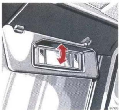
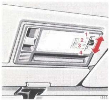
1 2 3 4 1353Interior Lamps
4 positions are provided for the switch of the forward lamp (combined interior/reading lamp).
Position 1: Interior/reading lamp switched on continuously.
Position 2: Interior/reading lamp switched off continuously.
Position 3: Reading lamp switched on continuously.
Position 4: The interior lamp is switched on by the front door contact switches and switched off with delay action.
natural_image
Black and white illustration of a stylized open book with a circular emblem on the cover (no text or symbols)The rear passenger compartment lamp is switched on and off by the rear door contact switches or by the rocker switch on the instrument panel.
text_image
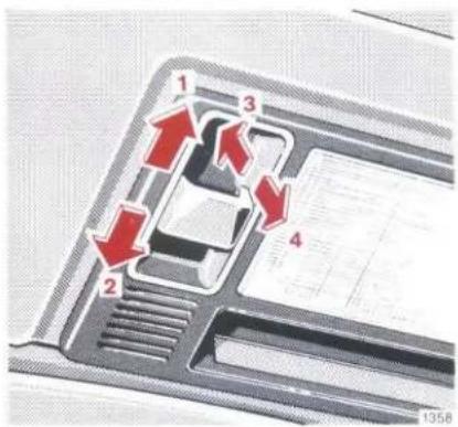
1 2 3 4 1358Pop-up/Sliding Roof
Turn key to steering lock position 1 or 2.
Actuating the switch,
1 open
2 close
3 raise
4 lower
the pop-up/sliding roof.
The switch is illuminated when the vehicle exterior lights (except for the standing lights) are switched on.
If the electric drive fails, the pop-up/sliding roof can also be moved manually (see page 100).

text_image
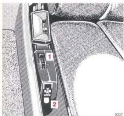
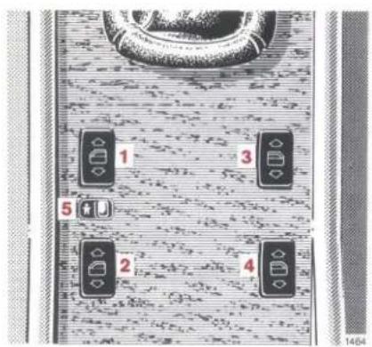
1 3 5 2 4 1464Electric Window Lifts
Switch group for window lifts:
1 Front, left
2 Rear, left
3 Front, right
4 Rear, right
5 Safety switch
Key in steering lock in position 1 or 2. The side windows can be operated as follows:
natural_image
Interior view of a car showing the front side panel and dashboard (no text or symbols visible)- By a switch group on the forward end of the tray, with one switch for each window (1-4).
- By means of single switch (6) below each rear window. If the operation of the rear windows is to be prevented (e.g. by children), push safety switch (5) to the right (symbol visible).
To eliminate a possible source of danger to children left alone in the vehicle, the key should always be removed, however short the time.
With the key withdrawn or in steering lock position 0 the window panes can be raised or lowered only if one of the front doors is opened.
Note:
The battery is likely to run down if the vehicle is parked for an extended period with one of the front doors opened.
Driving
| Automatic Locking Differential (ASD) | 70 |
| Automatic Transmission | 59 |
| Automatically Engaging Four-wheel Drive (4MATIC) | 71 |
| Brake Pad Wear Indicator | 68 |
| Brake System with ABS (Anti-lock Braking System) | 69 |
| Brake Warning Lamp | 69 |
| Bulb Failure Indicator Lamp | 67 |
| Charge Indicator Lamp | 66 |
| Coolant Level Indicator Lamp | 67 |
| Coolant Temperature Gauge | 67 |
| Engine Oil Consumption | 63 |
| Engine Oil Level Indicator Lamp | 66 |
| Fuel Consumption | 63 |
| Fuel Cut-off on the Overrun | 66 |
| Fuel Reserve Warning Lamp | 68 |
| Gauge for Economical Driving (ECONOMY) | 65 |
| Manual Transmission | 58 |
| Oil Pressure Gauge | 66 |
| Outside Temperature Gauge | 68 |
| Parking Brake | 58 |
| Snow Chains | 72 |
| Starting and Gear Changing | 58 |
| Tachometer | 66 |
| Tempomat | 62 |
| Trailer Operation | 73 |
| Travelling Abroad | 74 |
| Water Level Indicator Lamp for Windscreen Washer System and Headlamp Cleaning System | 68 |
| Winter Driving | 72 |

natural_image
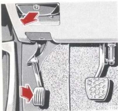
Mechanical lever mechanism diagram showing two stator buttons and a pedal mechanism (no text or symbols)Parking Brake
Depress parking brake pedal. With the key in steering lock position 2, the brake warning lamp in the instrument cluster comes on (function test of brake warning lamp).
To release the parking brake, pull handle on instrument panel. The parking brake is released instantaneously. The brake warning lamp in the instrument cluster must go out.
Starting and Gear Changing
Test the service brake after having pulled away.
Warm up the engine smoothly. Do not place full load on the engine until the operating temperature has been reached.
In order to prevent damage to the rear axle, never allow a single drive wheel to spin for an extended period when setting off on slippery ground.
text_image
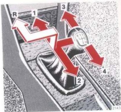
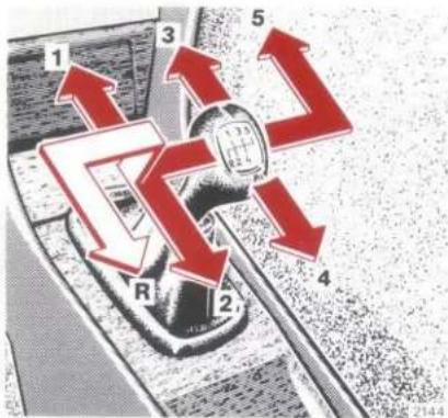
R 1 3 2 4Manual Transmission
See illustration for gearshift lever positions of the individual gears.
Shifting the reverse gear with the vehicle at standstill; to do this, lift up gearshift lever.
text_image
1 3 5 R 2 4 2144Do not exceed the maximum speed in the individual gears. See the markings on the speedometer.
Note:
To park the vehicle, engage 1st or reverse gear and depress parking brake pedal.
Automatic Transmission
The individual gears are changed automatically depending on
- selector lever position
● program selector switch position - driving speed
- accelerator position
Note:
When parking the vehicle or when working on the vehicle with the engine running, depress parking brake pedal and move selector lever to position "P".
Starting:
Move the selector lever into the desired position only when idling. The service brake should be actuated at the same time. The brakes should only be disengaged when the vehicle has started to move. With the selector lever in driving position the vehicle might otherwise start moving prematurely (creeping).
Accelerator position
Light throttle = early changing up = moderate acceleration
Full throttle = late changing up = rapid acceleration
Maximum acceleration is achieved by changing down into the next lower gear by means of the "kick-down", operated by depressing the accelerator pedal beyond the full throttle position. Once the desired speed is reached, reducing pressure on the accelerator will allow the transmission to change into a higher gear.

natural_image
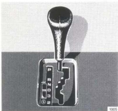
Mechanical gear shift lever with labeled ports (P, R, N, O, 3, 2) and a numeric scale (1005), no readable text or symbols beyond component labels.Selector lever positions
With the selector lever it is possible to adapt the gear changing sequence to suit any traffic conditions.
"P" Parking lock. An additional safety measure when parking the vehicle, it must only be engaged when the vehicle is stationary.
“R” Reverse gear. This should only be engaged with the vehicle at rest.
"N" Neutral. No power is transmitted from the engine to the rear axle. When the brakes are off, the vehicle can be moved freely (pushed, towed or tow-started). Do not engage "N" when driving except when the vehicle is in danger of skidding (e.g. on icy roads). See page 16.
"D" Drive. All gears are available. Position "D" affords optimum driving characteristics under all normal operating conditions.
“3” Shifting up to 3rd gear only. Suitable for moderate uphill and downhill gradients. As the transmission changes up to 3rd gear only, this position permits the utilization of the engine braking effect.
"2" Changes to 2nd gear only. Suitable for driving on steep mountain passes, for trailer operation in mountainous regions, for driving under severe operating conditions and as a braking position on extremely steep downhill gradients.
text_image
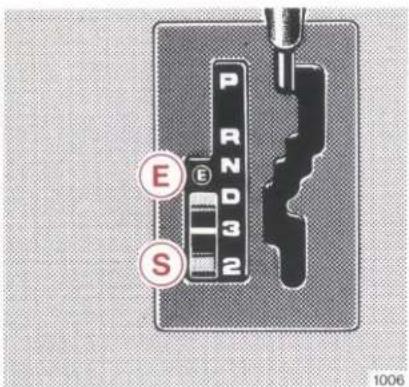
PRN D3 2 E S 1006Program selector switch
"S" Standard.
(Push switch forward – "S" becomes visible.)
In selector lever positions "D" and "3" the vehicle will start off in 2nd gear when accelerating gently. The vehicle will set off in 1st gear when accelerating briskly.
"E" Economy.
(Push switch to the rear – "E" becomes visible.)
In selector lever positions "D" and "3" the vehicle will start off in 2nd gear even with full
throttle. And even with high throttle, changes up and down will take place at driving speeds and engine speeds lower than in position "S".
Notes:
The "E" program affords an even smoother, more comfortable and fuel-saving way of driving and facilitates driving on slippery roads during the cold season.
As long as kickdown is applied the "E" program is cancelled automatically.
Important!
Do not exceed top speed in the individual selector lever positions. See line markings on the speedometer.
Change down (brake shift) to a lower selector lever position only if the vehicle speed will not exceed the maximum permissible engine speed in the desired selector lever position. Overrevving may otherwise cause damage to the engine.
On slippery roads, avoid brake shifts if possible.
Trailer operation
On uphill gradients, do not allow the engine speed to drop off excessively. Switch program selector switch to position "S" and change down to selector lever position "3" or "2" in good time (depending on gradient).
Stopping
When stopped for a short time, e.g. at traffic lights, leave the selector lever in the drive position and hold the vehicle with the service brake. When stopped for a longer time with the engine running, put the selector lever in the "N" position. Use brakes, not accelerator, to hold the vehicle on slopes. Thus unnecessary heating of the transmission can be avoided.
Manoeuvring
When manoeuvring in very restricted spaces, e.g. into parking spaces, control the driving speed by light application of the service brake. Depress accelerator only slightly, do not pump it.
To rock the vehicle out of soft ground (mud or snow), use moderate throttle and alternate between forward and reverse gears.

text_image
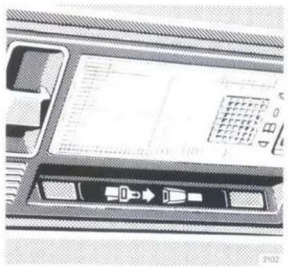
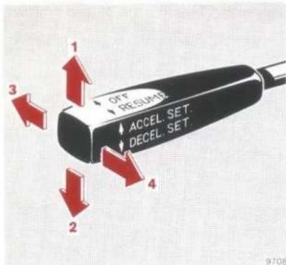
OFF RESUME ACCEL. SET. DECEL. SET 3 2 4 9708Tempomat
Any given speed above approximately 40 km/h can be maintained with the Tempomat by operating the switch.
1 Setting (touch switch)
Accelerating (hold switch)
2 Setting (touch switch)
Decelerating (hold switch)
Normally the vehicle is accelerated to the desired speed with the accelerator. Speed is set by briefly pushing the switch to position 1 or 2, and the accelerator can be released.
The speed can be increased (e.g. for passing) by using the accelerator. As soon as the accelerator is released, the previously set speed will be resumed automatically.
If a set speed is to be increased or decreased slightly, e.g. to adapt to the traffic flow, retain switch in position 1 or 2 until the desired speed is reached. When the switch is released, the newly set speed remains.
The speed is increased or lowered by 1 km/h respectively by briefly touching the switch in position 1 or 2.
3 Cancelling
To cancel the Tempomat,
briefly push lever to position 3.
The Tempomat will be cancelled
when the brake pedal is
depressed or the vehicle speed
drops below approximately
40 km/h, e.g. on an uphill grad-
ient.
4 Resume
If the lever is briefly pushed to position 4 when driving at a speed exceeding approximately
40 km/h that speed is resumed which was set prior to the cancellation of the Tempomat. The most recently stored speed is cancelled when the key in the steering lock is reversed to position 1 or 0.
Note:
When travelling downhill and the engine braking effect is insufficient the set speed will be exceeded and the brake may have to be applied. If the brake pedal was not depressed the vehicle will settle on the set speed again as soon as the downhill gradient flattens off.
Important!
Only use the Tempomat if the traffic conditions make it advisable to travel at a steady speed.
Position "Resume" should be applied only if the driver is fully aware of this speed and wishes to resume this particular speed.
When driving with the Tempomat, the selector lever must not be shifted to position "N" as otherwise the engine will rev up.
Engine Oil Consumption
Engine oil consumption can only be determined after a considerable distance has been travelled. Initially, oil consumption may be higher than specified. Frequently driving the engine at high speeds will also result in higher oil consumption.
Oil consumption depends on the way of driving: max. 1.5 l/1000 km.
Fuel Consumption
Driving at extremely low ambient temperatures, in cities, in hilly terrain and over short distances as well as trailer operation will increase fuel consumption.
The installation of optional units (air conditioning) increases the consumption slightly.
The consumption curves represent the fuel consumption at a steady speed. Fuel consumption according to 80/1268/EWG.
line
| y (km/h) | 200 Autom | 200.4-Gang | 200.5-Gang | | -------- | --------- | ---------- | ---------- | | 40 | 5.5 | 5.8 | 6.0 | | 80 | 7.5 | 8.0 | 8.5 | | 120 | 10.0 | 11.0 | 11.5 | | 160 | 13.0 | 14.5 | 15.0 | | 200 | 16.0 | 17.5 | 18.0 |200
Manual four-speed transmission
| Urban: | 11.2 l/100 km |
| At 90 km/h: | 6.7 l/100 km |
| At 120 km/h: | 8.5 l/100 km |
Manual five-speed transmission
| Urban: | 11.2 l/100 km |
| At 90 km/h: | 6.1 l/100 km |
| At 120 km/h: | 7.7 l/100 km |
Automatic transmission
| Urban: | 11.0 l/100 km |
| At 90 km/h: | 7.2 l/100 km |
| At 120 km/h: | 9.0 l/100 km |
200 E
Manual four-speed transmission
| Urban: | 11.0 l/100 km |
| At 90 km/h: | 6.8 l/100 km |
| At 120 km/h: | 8.7 l/100 km |
Manual five-speed transmission
| Urban: | 11.0 l/100 km |
| At 90 km/h: | 6.3 l/100 km |
| At 120 km/h: | 8.0 l/100 km |
Automatic transmission
| Urban: | 10.9 l/100 km |
| At 90 km/h: | 7.2 l/100 km |
| At 120 km/h: | 8.9 l/100 km |

line
| V (km/h) | 230 E/CE Autom | 230 E | 230 E/CE 5-Gang | | -------- | -------------- | ----- | --------------- | | 40 | 5 | 5 | 5 | | 80 | 7 | 7 | 7 | | 120 | 10 | 10 | 10 | | 160 | 15 | 15 | 15 | | 200 | 20 | 20 | 20 | | 240 | 25 | 25 | 25 |230 E, 230 CE
Manual four-speed transmission
| Urban: | 11.1 l/100 km |
| At 90 km/h: | 6.8 l/100 km |
| At 120 km/h: | 8.5 l/100 km |
Manual five-speed transmission
| Urban: | 11.1 l/100 km |
| At 90 km/h: | 6.2 l/100 km |
| At 120 km/h: | 7.7 l/100 km |
Automatic transmission
| Urban: | 10.9 l/100 km |
| At 90 km/h: | 7.1 l/100 km |
| At 120 km/h: | 8.7 l/100 km |
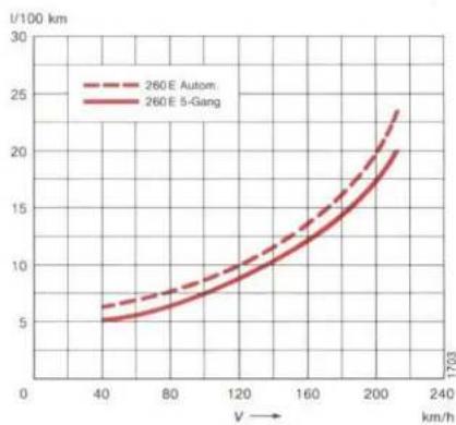
line
| V (km/h) | 260E Autom (I/100 km) | 260E 5-Gang (I/100 km) | |---|---|---| | 40 | 6.0 | 5.5 | | 80 | 8.0 | 7.0 | | 120 | 10.5 | 9.5 | | 160 | 13.5 | 12.5 | | 200 | 18.0 | 16.5 | | 240 | 23.5 | 20.5 |260 E
Manual five-speed transmission
| Urban: | 12.4 l/100 km |
| At 90 km/h: | 6.9 l/100 km |
| At 120 km/h: | 8.8 l/100 km |
Automatic transmission
| Urban: | 12.4 l/100 km |
| At 90 km/h: | 8.2 l/100 km |
| At 120 km/h: | 9.9 l/100 km |
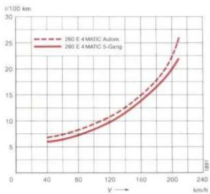
line
| V (km/h) | 260 E 4 MATIC Autom. (l/100 km) | 260 E 4 MATIC 5-Gang (l/100 km) | | -------- | ------------------------------ | ------------------------------- | | 40 | 7.0 | 6.0 | | 80 | 9.0 | 8.0 | | 120 | 12.0 | 11.0 | | 160 | 16.0 | 15.0 | | 200 | 22.0 | 21.0 | | 240 | 26.0 | 23.0 |260 E 4MATIC
Manual five-speed transmission
| Urban: | 13.4 l/100 km |
| At 90 km/h: | 7.7 l/100 km |
| At 120 km/h: | 9.7 l/100 km |
Automatic transmission
| Urban: | 12.9 l/100 km |
| At 90 km/h: | 8.7 l/100 km |
| At 120 km/h: | 10.6 l/100 km |
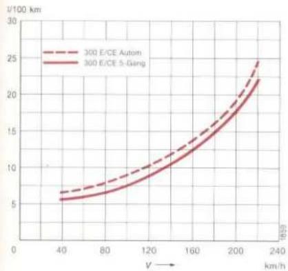
line
| V (km/h) | 300 E/CE Autom | 300 E/CE 5-Gang | | -------- | -------------- | --------------- | | 40 | 6 | 5 | | 80 | 8 | 7 | | 120 | 10 | 9 | | 160 | 13 | 12 | | 200 | 18 | 17 | | 240 | 25 | 22 |300 E, 300 CE
Manual five-speed transmission
| Urban: | |
| 300 E | 12.7 l/100 km |
| 300 CE | 13.0 l/100 km |
| At 90 km/h: | 6.8 l/100 km |
| At 120 km/h: | 8.7 l/100 km |
Automatic transmission
| Urban: | 12.8 l/100 km |
| At 90 km/h: | 8.3 l/100 km |
| At 120 km/h: | 10.0 l/100 km |
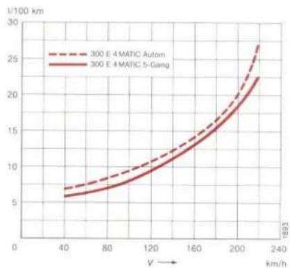
line
| V (km/h) | 300 E 4 MATIC Autom | 300 E 4 MATIC 5-Gang | | -------- | ------------------- | -------------------- | | 40 | 6.5 | 6.0 | | 80 | 9.0 | 8.0 | | 120 | 12.0 | 11.0 | | 160 | 16.0 | 15.0 | | 200 | 22.0 | 21.0 | | 240 | 27.0 | 25.0 |300 E 4MATIC
Manual five-speed transmission
| Urban: | 13.9 l/100 km |
| At 90 km/h: | 7.5 l/100 km |
| At 120 km/h: | 9.5 l/100 km |
Automatic transmission
| Urban: | 13.5 l/100 km |
| At 90 km/h: | 8.9 l/100 km |
| At 120 km/h: | 10.7 l/100 km |
Gauge for Economical Driving (ECONOMY)
The gauge for economical driving points out the fuel consumption tendency in the various driving modes.
If the pointer is in the red field on the RH side, this means a higher fuel consumption; if it is in the black field on the LH side, this indicates more economical driving. This applies to the respective gear engaged.
The gauge is not designed for consumption comparisons in the individual gears. Here applies the following rule: When driving at a given speed, consumption will be lower in the higher gear, although the pointer generally will be in the red field.

Tachometer
Red marking on the tachometer: engine overspeed range. This range should always be avoided. To protect the engine the fuel supply is interrupted as soon as the marking is reached.
Fuel Cut-off on the Overrun
In the overrun the fuel supply is cut off only if the foot is eased off the accelerator completely.
Oil Pressure Gauge
At operating temperature, the operational reliability of the engine is not jeopardized if the oil pressure at idling drops to 0.3 bar gauge pressure.
However, the oil pressure must increase immediately upon acceleration.
Engine Oil Level Indicator Lamp
The indicator lamp comes on when the key in the steering lock is in position 2. It must go out when the engine is running.
If this lamp comes on while the engine is running at operating temperature, the oil level has dropped close to the lower mark on the dipstick. The warning lamp will light up only briefly at first, but it will stay on if the oil level continues to drop. If there is no leak (loss of oil) and the oil pressure is not dropping, you can drive on to the next petrol station. We recommend that you add 1 liter of engine oil there.
There is also a dipstick in the engine for checking the oil level after refuelling or before setting off on a long journey, for instance (see page 78).
Charge Indicator Lamp
Should the charge indicator lamp fail to come on prior to starting when the ignition key is in position 2 or should it fail to go out after starting or during the ride, this indicates a fault which must be repaired at a MERCEDES-BENZ service station as soon as possible.
If the charge indicator lamp comes on while the engine is running, the poly V-belt may have snapped. In this case the poly V-belt must be replaced before the trip is continued. Otherwise the resulting water pump failure could cause overheating and thus possibly engine damage.
Coolant Temperature Gauge
Correctly blended anticorrosion/antifreeze coolant in the overpressure cooling system will boil only at approx. 130 °C.
The coolant temperature may rise to the red marking in the case of high ambient temperatures and when travelling in mountainous terrain.
Coolant Level Indicator Lamp
The indicator lamp comes on when the key is in steering lock position 2 and must go out when the engine is running.
If it comes on while the engine is running the coolant level has dropped below the specified level. Refill with coolant (see page 77) and determine the cause of the coolant loss.
Bulb Failure Indicator Lamp
At key position 2 in steering lock the indicator lamp weakly lights up and should go out with the engine running.
Flashing of indicator lamp at key position 2 in steering lock or with the engine running indicates the failure of a lamp bulb.
If a bulb of the vehicle exterior lighting is burnt out, the indicator lamp only lights up as long as the exterior vehicle lighting is switched on.
If a bulb of the stop lamps or the turn signal lamps is burnt out, the indicator lamp lights up when braking or actuating the turn signal and goes out only after the engine is shut off.
Note:
The indicator lamp also lights up when a wrong type of bulb is installed.
If additional illumination equipment is installed at a later date, it must be connected with the fuse (upstream of the bulb monitor).
If this is not observed, the bulb failure indicator lamp may be affected or the monitoring unit damaged.

Water Level Indicator Lamp for Windscreen Washer System and Headlamp Cleaning System
The warning lamp comes on when the key is in steering lock position 2 and must go out when the engine is running.
If the lamp comes on while the engine is running the water level has dropped to approx. one quarter of the reservoir volume. Top up with water plus MB windscreen washing detergent S for summer or W for winter at the next opportunity. The reservoir for the windscreen washing system and the headlamp cleaning system is in the engine compartment (see page 136).
Fuel Reserve Warning Lamp
The warning lamp comes on when the key is in steering lock position 2 and must go out when the engine is running.
Should the warning lamp fail to go out after the engine has started or should it come on while driving, the fuel reserve level has been reached.
Fuel reserve and capacity, refer to page 128 and last page.
Outside Temperature Gauge
To measure the ambient air temperature a temperature sensor is mounted in the region of the front bumper.
Note:
If the gauge indicates temperatures above the freezing point, this does not necessarily mean there will be no ice on the road. This is particularly applicable to roads which cut through woods or to bridges.
Brake Pad Wear Indicator
The brake pad wear indicator in the instrument cluster comes on when the steering lock key is turned to driving position 2 and must go out when the engine is idling. If the indicator lights up during braking, this indicates that the front wheel brake pads are worn.
The brake system should be checked at a MERCEDES-BENZ service station as soon as possible.
Brake Warning Lamp
The brake warning lamp in the instrument cluster comes on if the brake fluid level in the reservoir is too low (key in steering lock position 2 and parking brake disengaged).
As soon as the brake fluid level has dropped to the minimum mark on the reservoir, have brake system inspected (for brake pad thickness and leaks).
To test the brake warning lamp, depress parking brake pedal. With the key in steering lock position 2, the brake warning lamp must come on. It must go out again as soon as the parking brake is released.
Brake System with ABS (Anti-lock Braking System)
ABS prevents locking of wheels above a speed of approx. 3 km/h independent of road condition. A prerequisite is, however, that the speed amounts to at least 8 km/h when the brakes are applied.
Should a wheel threaten to lock when braking, the brake pressure controlling action of the ABS causes the vehicle to vibrate and the brake pedal to pulsate slightly. The driver is thus aware that the ABS is working correctly. On a slippery road, e.g. on ice and snow, this may occur when even slight pedal pressure is applied. Pulsation of the brake pedal may then be considered a hint to adapt one's driving style to the prevailing difficult road conditions.
The ABS indicator lamp in the instrument cluster comes on when the key is in steering lock position 2 and must go out when the engine is operating.
If the voltage drops below approx. 10 volts, the indicator lamp will also come on and the ABS is switched off. As soon as the voltage rises above this level again, the indicator lamp goes out and the ABS is operational again.
Should the ABS indicator lamp fail to go out, this indicates that the ABS is switched off because of a fault. In this case the brake system performs its regular function but without the anti-locking capability. Have the ABS checked at a MERCEDES-BENZ service station as soon as possible.
Note:
The ABS cannot offset the effects of excessive cornering speeds or of failing to maintain a safe distance behind another vehicle.
Automatic Locking Differential (ASD)
The automatic locking differential cuts in if a speed difference (skid) occurs between front and rear wheels in excess of 2 km/h and the vehicle speed is less than 25 km/h. It cuts out again as of 50 km/h.
The yellow operation indicator lamp in the speedometer will always come on if the speed difference between front and rear wheels exceeds 2 km/h (slippery road warning).
Note:
The automatic locking differential will not cut in any more at speeds above 25 km/h. However, a torque dependent locking effect of up to a maximum of 35% will always be produced.
With the key in steering lock position 2 the function indicator lamp and the yellow ASD indicator lamp in the instrument cluster come on and must go out when the engine is running.
There is a fault in the system if the ASD indicator lamp comes on while the engine is running. Have the automatic locking differential checked at a MERCEDES-BENZ service station as soon as possible.
Notes:
When the parking brake is tested on a brake test bench, the engine must be stopped to prevent engagement of automatic locking differential.
During winter operation maximum efficiency of the automatic locking differential can be attained with M + S radial-ply tires only.
Automatically Engaging Four-wheel Drive (4MATIC)
When the key is in steering lock position 2 the yellow operation indicator lamp in the speedometer and the yellow 4MATIC indicator lamp come on and must go out when the engine is running.
The operation indicator lamp comes on while driving when the front wheel drive or the front wheel drive and the differential lock(s) are engaged.
Front wheel drive and differential locks engage automatically as soon as one or more wheels start slipping (difference between speeds of front and rear wheels) because of road conditions or driving style.
When the operation indicator lamp comes on the driver is informed that the tires have reached their adhesion limit.
The driving style must always be adapted to the road conditions, even if the vehicle is equipped with 4MATIC.
Notes:
If the 4MATIC indicator lamp comes on (possibly at the same time as the operation indicator lamp) while the engine is running, this indicates a fault. In this case, turn service switch on the right-hand side of the engine compartment to the stop in position 2. The vehicle will then be driven by the rear axle only.
On vehicles equipped with level control this system is deactivated if the service switch is in position 2.
A faulty 4MATIC system should be checked at a MERCEDES-BENZ service as soon as possible.
Before the vehicle is driven on chassis dynamometers the service switch must be turned to position 2. The 4MATIC indicator lamp comes on and only goes out again when the service switch is turned to position 1. A maximum testing time of 15 minutes on the dynamometer must not be exceeded.
If the service switch is in position 2, the level control is deactivated.
When towing the vehicle, comply with instructions on page 93.
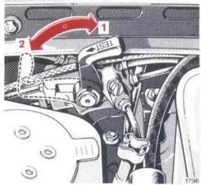
text_image
1 2 1371 1796Service switch
1 Operating position
2 Test position

Winter Driving
Have your car winterized at a MERCEDES-BENZ service station before the onset of winter.
- Engine oil change: If no year-round oil is used, pour in an engine oil which is approved for winter operation. For viscosity (SAE grade) and capacity, see "Service Products" and last page.
● Have percentage of anticorrosion/antifreeze agent checked. -
Additive in the windscreen and headlamp cleaning system: Add MB windscreen washing detergent (W) for winter operation to the water.
-
Battery check: Battery capacity drops with decreasing ambient temperature. Certain starting even at low ambient temperatures can only be assured by a well charged battery.
- Tyres: We recommend M + S radial tyres on all wheels for the winter season. Observe permissible maximum speed for M + S radial tyres and the legal speed limit.
Note:
During winter operation maximum efficiency of the automatic locking differential can be attained with M + S radial-ply tires only.
Snow Chains
Only use snow chains tested and recommended by us. Any MERCEDES-BENZ service station will readily advise you.
Snow chains can be used on rear wheels only. Comply with manufacturer's fitting instructions. Remove the wheel embellishers when fitting the snow chains.
Retention the newly fitted snow chains after driving for a short while.
The permissible maximum speed (50 km/h) must only be driven on snow covered roads. On roads clear of snow, remove snow chains as soon as possible.
For driving instructions in case of slippery roads, refer to page 16.
Trailer Operation
Comply strictly with the mounting/removal instructions for the trailer coupling with detachable ball neck.
When operating the trailer it must be taken into consideration that the driving characteristics of the car/trailer combination differ from the driving characteristics of the vehicle without trailer. The combination is heavier, its ability to accelerate and its gradeability are limited and long braking distances are required. It is more susceptible to gusts of side wind and demands more responsive steering.
By nature the fuel consumption is higher in trailer operation.
When loading a trailer, ensure that neither the GVW of the trailer nor the permissible trailer loads of the vehicle or the trailer coupling are exceeded. Permissible values are shown in the vehicle documents and on the identification plates of the trailer coupling and the trailer. The lowest value will apply.
The permissible drawbar load on the ball head of the trailer coupling must not be exceeded either. Maximum drawbar load is 75 kg (see sticker on the loading edge of the boot), but it must not exceed the value given on the identification plates of the trailer coupling and of the trailer. We recommend you to exploit the maximum permissible drawbar load, but definitely to adhere to a minimum of 40 kg.
Keep in mind that the vehicle payload will have to be reduced on account of the drawbar load. The permissible rear axle load must not be exceeded either.
We recommend you not to exceed the top speed of 80 km/h not even in countries which permit higher speeds.
If possible do not brake abruptly, but only slightly touch the brake pedal so the trailer will push. Only then brake firmly.
Should the trailer start swaying, decelerate, do not counter-steer, brake if necessary. Never attempt to straighten the combination by accelerating.
The data on hill-starting ability recorded under "Technical Data" refer to sea level. When driving in the mountains it must therefore be taken into consideration that engine power and hill-starting ability decrease as altitude increases.
Note:
Do not uncouple trailer equipped with overrunning brake in overrun condition. The rebound action of the overrunning brake system might otherwise inflict damage on the bumper.
Constant current for caravan
Vehicles with 13-pole socket have been fitted with a permanent current cable which is not connected to the auxiliary fuse box. Have the permanent current cable connected by a MERCEDES-BENZ workshop.
Trailers with 7-pole plugs
With the enclosed adapter cable vehicles with a 13-pole socket and trailers with a 7-pole plug can be connected.

Travelling Abroad
Abroad, too, you have a widely-spread MERCEDES-BENZ service network at your disposal. Additional indexes are available from your MERCEDES-BENZ service station, if you travel into areas which are not listed in your service station index.
Your vehicle is equipped with asymmetrical headlights, therefore, should you be driving in a country in which the traffic travels on the opposite side of the road to that in your home country, it is possible to correct the prismatic effect by attaching an opaque corrective adhesive tape to the lenses.
In some countries it may be possible to obtain only fuel with an insufficient octane number. In this instance a MERCEDES-BENZ service station can adjust the timing to the octane number of the fuel within certain limits (does not apply to countries having exhaust emission legislation). This timing adjustment is authorized as a temporary emergency measure only and full load must then not be imposed on the engine. This measure will furthermore result in an engine power drop and increased fuel consumption.
Practical Tips
| Air Cleaner Maintenance Indicator | 77 | Hazard Warning Triangle Headlamp Setting | 80 |
| Ashtrays | 98 | Jack | 81 |
| Battery | 90 | Jump Starting | 91 |
| Bonnet | 76 | Operation Diagramm of Poly-V-belt | 102 |
| Boot Lamp | 80 | ||
| Changing Wheels | 83 | Rear Seat Cushion | 98 |
| Changing Wiper Blades | 99 | Replacing Bulbs | 88 |
| Cleaning and Care of the Vehicle | 93 | Roof Rack | 101 |
| Coolant Inspection | 77 | Safety Headrests on the Front Seats | 97 |
| Emergency Operation of Pop-up/Sliding Roof | 100 | Spare Parts Service | 103 |
| Emergency Release of Fuel Filler Flap | 100 | Spare Wheel | 81 |
| Engine Oil Level Check | 78 | Spark Plugs | 91 |
| Fire Extinguisher | 98 | Stowage Area Beneath Boot Floor | 81 |
| First Aid Kit | 80 | Tool Kit | 81 |
| Fluid Level in Automatic Transmission | 79 | Tow-starting and Towing the Vehicle | 92 |
| Fuses | 86 | Tyre Pressure | 85 |
| Wheels, Tyres | 82 |

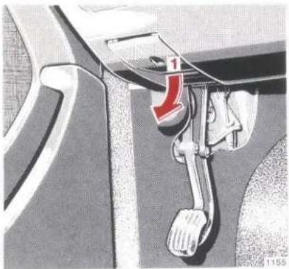
natural_image
Mechanical component diagram showing a lever mechanism with a red arrow indicating direction (no text or symbols present)Bonnet
Opening:
Pull handle (1) for unlocking bonnet at the left under instrument panel. Handle (2) will simultaneously jump out of radiator grille (slightly lift bonnet if required).
natural_image
Front view of a Mercedes-Benz car grille with logo and red arrow (no text or symbols)Pull handle (2) out of the radiator grille up to the stop and open bonnet (do not lift by the handle!). When doing this the windscreen wiper arm must not be folded forward.
Closing:
Close by slamming bonnet energetically down.
Notes:
A risk of injury prevails when the bonnet is opened with the engine running.
The engine is fitted with a transistorized ignition system. Because of the high ignition voltage it is very dangerous to touch the components of the ignition system (ignition coil, ignition distributor, ignition cables, spark plug connectors, test socket) if
● the engine is running
● the engine is being started
● the key in the steering lock is in position 2 and the engine is cranked by hand.
Air Cleaner Maintenance Indicator
On vehicles with air cleaner maintenance indicator, service or renew filter element if the red field appears in the window of the maintenance indicator. After cleaning, reset red field by depressing the catch.
Coolant Inspection
The coolant reservoir with the filler neck is arranged separately from the radiator. For checking the coolant level the vehicle should be placed on a level surface.
Open coolant reservoir only if the coolant temperature is below 90 °C.
Turn cap to the preliminary notch to relieve excess pressure. Only then continue turning the cap and detach.
If the coolant reservoir is opened immediately the excess pressure will eject hot coolant and vapour.
The coolant level must reach:
● to marking on the reservoir if the coolant is cold,
● about 1.5 cm in higher if the coolant is hot.
natural_image
Close-up of a car engine compartment with a red arrow pointing to a component (no visible text or symbols)1 Coolant filler neck
2 Coolant level marking
The drain plugs are on the RH side of the engine and on the radiator bottom.
For anticorrosion/antifreeze agents, refer to "Service Products", page 130.

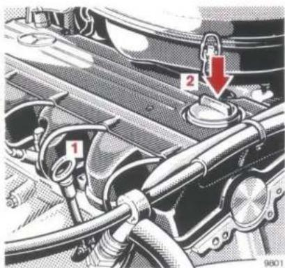
text_image
Technical diagram of a car engine bay with labeled components and a red arrow indicating a switch or lock mechanism.200, 200 E, 230 E, 230 CE
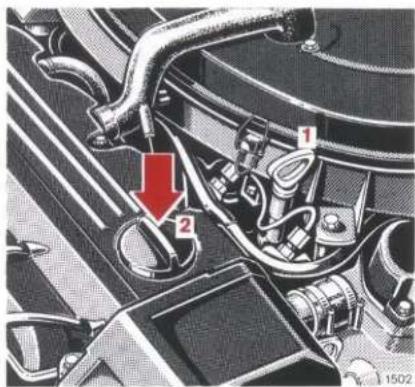
text_image
Technical diagram of an engine component with numbered parts and a red arrow indicating a specific part.260 E, 300 E, 300 CE, 260 E 4MATIC, 300 E 4MATIC
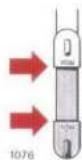
If the engine must be topped up, fill up to the upper (max) marking but do not exceed the upper marking.
For viscosity and capacity, refer to "Service Products" on the last page.
For engine oil level indicator lamp, refer to page 66.
Engine Oil Level Check
1 Dipstick 2 Oil filler hole
Check engine oil level with the engine at operating temperature. The operating temperature should have been reached quite some time ago.
Check oil level with the vehicle standing on a level surface and the engine turned off – e.g. after refueling.
Wipe dipstick prior to every measurement.
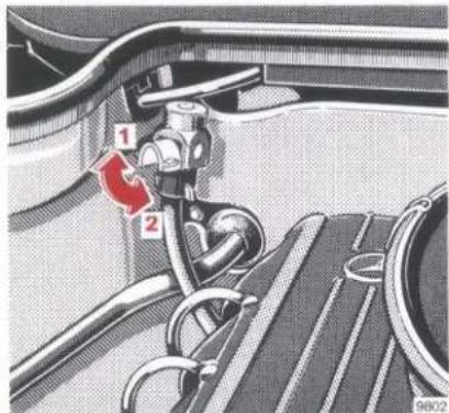
text_image
Technical diagram of a car intake system with labeled parts 1 and 2, showing mechanical components and wiring.Fluid Level in Automatic Transmission
Check fluid level in automatic transmission regularly and prior to each long trip.
Check transmission fluid level with the engine idling, parking brake engaged and selector lever in position "P". The vehicle must be parked on level ground. Before the check, allow engine to idle for approx. 1 to 2 minutes.
Measure fluid level with the dipstick completely inserted and the locking lever released (1).
Painstaking cleanliness must be observed. To wipe the dipstick, use a clean, lint-free cloth (or better still leather). To fill the transmission with fluid, only pour it through a fine-mesh filter into the dipstick opening. Even the slightest impurity may cause operational troubles.
The fluid level in the transmission changes with the temperature. The markings on the dipstick (max. and min.) refer to a fluid temperature of 80 °C – normal temperature with the transmission warm.
At a fluid temperatur of 20 – 30 °C, however, the maximum fluid level is about 10 mm (200, 200 E, 230 E/CE, 260 E: 12 mm) below the dipstick minimum marking. This information serves as a guide for fluid change which is generally carried out at this temperature.
The fluid level should not exceed the upper mark and any surplus fluid should be drained or syphoned off.
Then push dipstick all the way in and swing locking lever downwards (2).

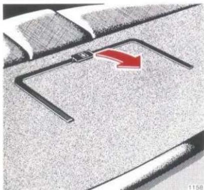
natural_image
Close-up of a car's side profile with a red arrow pointing to the front wheel (no text or symbols visible)First Aid Kit
The first aid kid is stowed in a covered recess in the hat shelf at the rear.
Check contents of first aid kit regularly for completeness and serviceability.
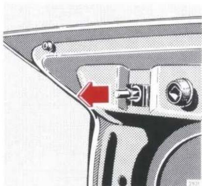
natural_image
Mechanical component diagram showing a lever mechanism with a red arrow indicating direction (no text or symbols present)Boot Lamp
If the boot lid is to remain open for an extended period of time, the boot lamp can be switched off by pulling out the contact pin (arrow).
The boot lamp is switched on again as soon as the boot lid is closed and re-opened.
Note:
The contact pin cannot be pulled out on vehicles equipped with burglar-alarm system.
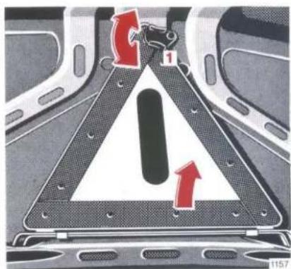
text_image
Diagram showing a warning sign with red arrows and number 1, indicating traffic flow or safety instructions.Hazard Warning Triangle
The hazard warning triangle is attached to the inner side of the trunk lid.
Release hazard warning triangle (1) and remove it upwards.
natural_image
Mechanical gear mechanism diagram with a red arrow indicating rotational direction (no text or symbols)Stowage Area Beneath Boot Floor
Fold back mat in the boot, grasp into opening in the cover and lift it up.
Tool Kit
The tool kit is in the stowage area beneath boot floor.
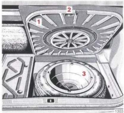
text_image
Technical diagram of a mechanical device with numbered components, likely an optical or mechanical assembly.Spare Wheel
Fold back the mat, lift boot floor (1) and engage clamp (2) in the boot edge.
To remove the spare wheel, turn the bowl (3) to the left and remove.
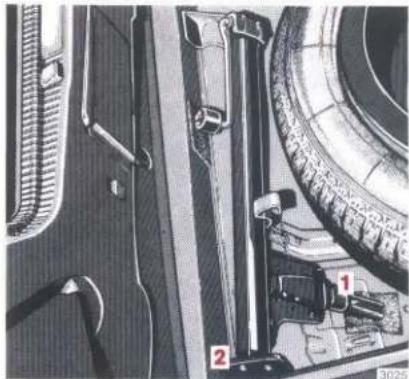
natural_image
Close-up of mechanical components with numbered labels (1, 2) and part numbers (3025), no readable text or symbols beyond labels.Jack
For stowage position, refer to illustration.
Jacking pin (1) must be turned in almost down to base (2) of the jack and should rest on the felt in the spare wheel trough.
Note:
The jack is exclusively intended for jacking up the vehicle. When working under the vehicle, jack stands must be used.
Wheels, Tyres
Only use wheels and tyres of identical brand, design and version.
Your MERCEDES-BENZ service station has all the information on tested and recommended summer and winter tyres. Please allow them to advise you on all questions concerning wheels and tyres.
Mount single newly acquired tyres on the front wheels. If any tyres are replaced and the spare tyre is new and of the same make and version, mount the spare wheel on the vehicle as road wheel. We recommend that you run in new tyres for approx. 100 km at moderate speed.
On new disk wheels the wheel bolts must be retightened after 100 - 500 km. Tightening torque is 110 Nm.
To prevent damage to the valves, vehicles equipped with steel disk wheels must only be driven with the wheel embellishers installed.
For tyre sizes see "Technical Data".
Note:
When using retreaded tyres proceed with care. Retreaded tyres are not tested and approved by us. Different carcasses and a generally unknown history of such tyres may lead to deteriorations with regard to driving performance and driving safety.
Interchanging wheels: The wheels can be rotated according to the degree of tyre wear while retaining the same sense of rotation. Rotating, however, should be carried out before the characteristic tyre wear pattern (shoulder wear on front wheels and tread center wear on rear wheels) becomes visible at a mileage of 5000 - 10 000 km as otherwise the driving properties deteriorate.
Tyre damage like pealing tread or breakage of cleats etc. can be caused by slowly leaking air (e.g. due to a nail in the tyre). Regular tyre pressure checks (including spare tyre) at intervals of no more than 14 days are therefore essential.
For the tyre pressure checks, keep in mind that warm tyres show higher pressure than cold tyres. See tyre pressure chart. Should the tyre pressure decrease constantly, definitely check whether foreign bodies have penetrated the tyre or if disk wheel or valve allow the air to leak.
Only use original MERCEDES-BENZ wheel securing bolts (marked with a Mercedes star)! Longer bolts are required for light alloy disc wheels than for steel disc wheels (see figure on page 83).
Thoroughly clean the inner side of the wheels any time you interchange the wheels or wash the underside of the vehicle.
Dented, bent or corroded rims cause tyre pressure loss and damage to the tyre beads. For this reason, check rims for damage at regular intervals. Derust sheet steel disk wheels and spot paint, if required.
Check rim flanges of light alloy disk wheels for wear before a tyre is mounted. Remove burrs, if required.
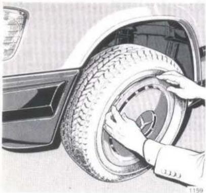
natural_image
Close-up of hands cleaning a car tire with a handle (no text or symbols visible)Changing Wheels
- Engage parking brake.
- With manual transmission, put the gear lever in first or reverse gear position, with automatic transmission, select the park position "P".
- Prevent the vehicle from rolling away by placing wheel chocks on the downhill side of the two opposite wheels when the vehicle is on a slope and in front of and behind the opposite front wheel on level roads.
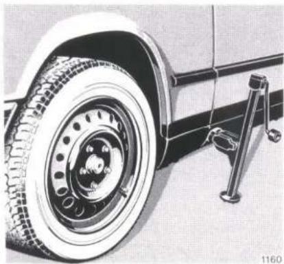
natural_image
Close-up of a vintage car tire mounted on a vehicle, showing wheel rim and suspension bracket (no text or symbols visible)- Remove wheel embellishers with both hands. If the wheel embellishers are stuck, insert a screw-driver between wheel and embellisher and press screw-driver handle against the tyre.
- Loosen the wheel bolts with the combination wrench but do not remove them as yet.
Observe wheel securing bolts.
1 For light alloy disk wheel only
2 For steel disk wheel only
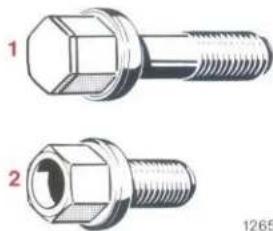
natural_image
Technical illustration of two hexagonal bolt components (no text or symbols)-
Saloon: Pull protective cap out of the jack application tube.
Coupé: Remove cover of jack application tube. For this purpose, insert a screwdriver in the recess and pry out cover. Jack application tubes are behind the front wheel houses and in front of the rear wheel houses. -
Insert the jack arm into the hole all the way to the stop. Position the jack so that, seen from the side of the vehicle, it is always vertical – even on slopes. Jack up the vehicle until the wheel is clear of the ground.
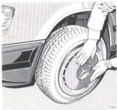
natural_image
Illustration of a car tire being cleaned with a hand, showing tire damage and wheel (no text or symbols)- Now remove the wheel bolts completely. Protect the threads from dirt and sand etc. when you put them down.
Light alloy disk wheel: It must be ensured that light alloy disk wheels do not tip over after the last wheel bolt has been turned out as otherwise the paintwork of the wheel may suffer damage.
-
Remove the wheel.
-
Light alloy disk wheel: Screw centering bolt (tool kit) into upper tapped hole.
- Set jack in such a manner that the wheel can be slipped on without requiring a lift.
- Slip on wheel and press on (with valve down). Screw in and slightly tighten the wheel bolts. Only use wheel bolts which are suitable for disk wheels.
Light alloy disk wheel: When screwing in the first wheel bolt, be sure the wheel cannot tip over as its paint-work could suffer damage. Remove centering bolt and install last wheel bolt. -
Lower vehicle and detach jack.
-
Saloon: Push protective cap into the jack application tube.
Coupé: Engage the hooks of the protective cap for the jack application tube at the upper end and firmly press on lower end. - Tighten the five wheel bolts by tightening every second bolt in turn. On new disk wheels the wheel bolts must be retightened to 110 Nm after 100 to 500 km.
- Fitting the wheel embellisher: First, position the tyre valve in the opening provided and press this section of the embellisher against the rim flange. Then press on the embellisher section (do not strike) opposite to the valve until it engages. When pressing on the wheel embellisher, be sure to correctly insert the clips into the disk wheel.
- Check and adjust tyre pressure.
Tyre Pressure
A table (see fuel filler flap or last page) lists the tyre inflation pressures specified for summer and winter tyres as well as for the varying operating conditions.
Caution:
The tyre inflation pressure changes by approx. 0.1 bar whenever the ambient air temperature changes by 10 °C. This must be kept in mind when checking the inflation pressure in a room of different ambient temperature, particularly during the cold season.
Example:
Room temperature = approx. + 20 °C Outside temperature = approx. 0 °C Inflation pressure to be set = specified tyre pressure + 0.2 bar.
Tyre pressures listed for light loads are minimum values offering high driving comfort. Increased inflation pressures for heavy loads produce favourable handling characteristics with lighter loads and are perfectly permissible. The ride of the vehicle, however, will become somewhat harder.
Tyre temperatures and pressures tend to increase in direct relation to speed and load. Thus, in normal circumstances, the tyre pressure should only be corrected when the tyres are cold. The pressure of warm tyres should only be corrected when, even after consideration of the prevailing operating conditions, the value is less than that shown in the table.

natural_image
Close-up of a car engine bay with hoses and a control panel (no visible text or symbols)Fuses
The fuse box is located in engine compartment.
To replace a fuse, loosen clamp (1), lift cover and remove.
A survey of the fused consumers is in cover of fuse box. The digits under the fuses are the same as those in the survey.
Before changing a burnt-out fuse, determine the cause of the short circuit.
Spare fuses are stored in the fuse box. Observe amperage and colour code.
Fuses must not be repaired or bridged.
After replacing fuse, engage cover of fuse box at the rear and secure with clamp (1).
Fuse designation
Direction of travel
text_image
A 1 2 3 4 E B 5 6 7 8 F C 9 10 11 12 G D 13 14 15 16 H1 Fuse 16 A (red)
Cigarette lighter,
switch, heated rear window,
glove box lamp,
radio
2 Fuse 16 A (red)
Wiper and washer system,
headlamp flasher,
relay, headlamp cleaning system,
terminal 86,
relay, comfort circuitry,
terminal 86
3 Fuse 8 A (white) Parking and tail lamps, right, headlamp warning buzzer; Illumination: number plate, instrument cluster, controls, headlamp cleaning system
4 Fuse 8 A (white) Fog lamp and rear fog lamp
5 Fuse 8 A (white) Stop lamp, instrument cluster, dome lamp, front, bulb monitoring unit, tempomat (cruise control), tachometer, trailer control unit
6 Fuse 8 A (white) Turn signal lamp, horn, ambient air temperature gauge, trip computer
7 Fuse 8 A (white) Back-up lamp, heater water valves, coolant pump, engine fan, washer heating system, control unit – Heizmatik climate control,
relay, auxil. fan terminal 86, electr. system of autom. transmission, change-over valve, ignition change-over blower, inside temperature sensor, (refrigerant compressor – fuse 16 A, red)
8 Fuse 8 A (white)
Parking and tail lamps, left,
9 Fuse 8 A (white)
Diagnostic terminal 6,
hazard warning system,
clock,
dome lamp, front
electronic radio,
vanity mirror illumination,
relay, comfort circuitry term. 86
10 Fuse 25 A (blue)
Heated rear window
11 Fuse 8 A (white)
Carburetor electrical system
12 Fuse 25 A (blue)
Blower motor
(vehicles without automatic climate control)
13 Fuse 8 A (white)
Dimmed beam, left
14 Fuse 8 A (white)
Dimmed beam, right
15 Fuse 8 A (white) Main beam, left
16 Fuse 8 A (white) Main beam, right, main beam indicator
A Fuse 16 A (red)
Orthopaedic seat back,
pop-up/sliding roof,
seat heater, front,
safety headrests on the rear
seat bench
B Fuse 16 A (red)
Safety belt handover arm,
adjustable heated outside
mirror,
roller sun visor
C Fuse 16 A (red)
Dome lamp, rear,
boot lamp,
safety belt handover arm,
seat back arrester,
central interlock system,
courtesy lamps,
rear compartment reading lamps,
automatic antenna,
control unit of seat adjustment
D Fuse 16 A (red)
Auxiliary fan
E Fuse 25 A (blue)
Adjustment of driver's seat and front passenger seat,
steering wheel adjustment – memory
F Fuse 25 A (blue)
Adjustment of driver's seat and front passenger seat,
steering wheel adjustment
G Fuse 25 A (blue)
Window lifts front left and rear right
H Fuse 25 A (blue)
Window lifts front right and rear
left
Auxiliary fuse box
(in fuse compartment)
Auxiliary heater
Fuse 8 A (white)
Fuse 16 A (red)
Additional fuse boxes
(next to the main fuse box)
Blower motor (vehicles with automatic climate control)
30 A fuse
Permanent current for trailer 16 A fuse (red)
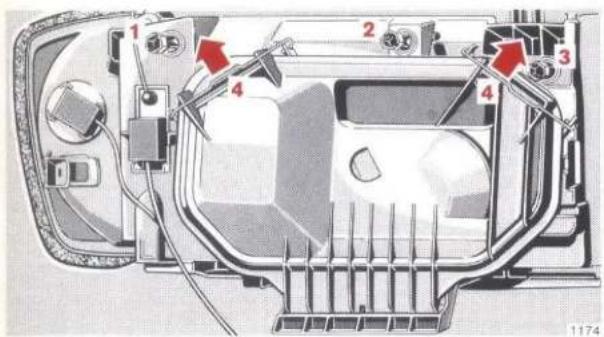
text_image
Technical diagram of a vehicle front panel with numbered components and red arrows indicating parts of the frame.Headlamp Setting
Check regularly. Have readjusted, if necessary.
Prior to adjustment, run engine and turn switch of headlamp beam control to "0" position.
Replacing Bulbs
Only handle new bulbs for head-lamps and taillamps with tissue paper or similar material.
Only install 12 V bulbs of the speci- fied wattage.
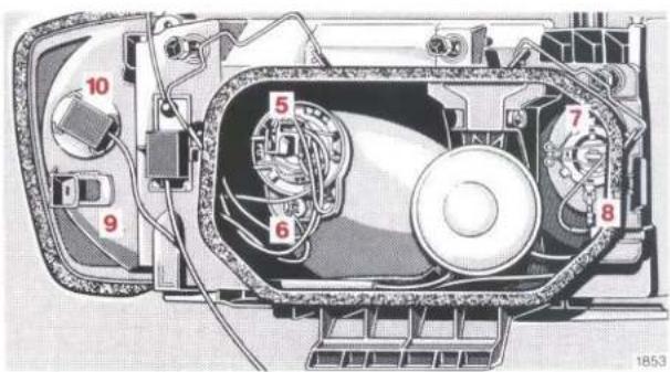
text_image
Technical diagram of an electronic device with numbered components, likely a motor or fan assembly.Headlamp Unit
1 Screw for headlamp horizontal aiming
2 Screw for headlamp vertical aiming
3 Screw for fog lamp aiming
4 Clamp for headlamp cap
5 Main and dipped beam bulb
6 Parking lamp and standing lamp bulb
7 Fog lamp bulb
8 Plug
9 Clamp for turn signal lamp housing
10 Bulb for turn signal lamp
Replacing Bulbs:
The bulb is changed from the engine compartment.
5 Bulb for main and dipped beam lamp H 4 (60/55 W): Disengage clamp 4. Press off cap and pull out of bracket.
Pull plug connection off the lamp base, disengage retaining spring and remove bulb. Install new bulb with the mounting flange guide lugs engaging the socket recesses.
6 Parking lamp and standing lamp bulb (4 W):
Disengage clamp 4. Press off cap and pull out of bracket.
Pull out lamp holder with bulb. Depress bulb, turn and remove
7 Fog lamp bulb H 3 (55 W): Disengage clamp 4. Press off cap and remove from bracket.
Pull out plug 8. Disengage retaining spring and remove bulb.
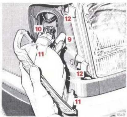
text_image
10 11 9 12 12 11 184910 Bulb for turn signal lamp (21 W): Compress clamp 9 and push out turn signal lamp housing forwards.
Turn left and detach lamp holder with bulb. Push bulb in, turn left and remove.
Slip lugs 11 of the turn signal lamp housing into guides 12 and push to the rear until the housing clips in place.
natural_image
Technical illustration of a vehicle or road segment with circular components and a cross symbol (no text or labels)Number Plate Lamps
(festoon bulb 5 W)
Loosen both the securing screws (1) and take out lamp.

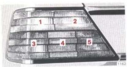
text_image
1 2 3 4 5
text_image
Technical diagram of a mechanical assembly with numbered components, likely a valve or connector assembly.Taillamp Units
1 Turn signal lamp (21 W)
2 Reversing lamp (21 W)
3 Stop lamp (21 W)
4 Taillamp/standing lamp (10 W)
5 Rear fog lamp (21 W) (on driver's side only)
Turn lock in boot counterclockwise up to stop and remove lamp holder. To change bulbs, push down, turn counterclockwise and remove.
Battery
Check fluid level in the cells approx. every 3 months. Check more often in summer and in hot zones.
Only replenish with distilled water. Do not use metal funnels and do not pierce the overfill protector.
The battery is filled to the maximum level when the water level in the filling chamber of the cell no longer drops.
If electrolyte is to be tapped from the battery for diagnostic purposes, pierce the overfill protector with the hydrometer or the end of the pipe connected to it.
Keep battery clean and dry.
The service life of a battery also depends on the state of charge. Only a battery which is charged sufficiently at all times will reach a maximum service life.
We therefore recommend having the battery charge checked frequently if the vehicle is used mainly in short-range traffic or if it is laid up for an extended period.
Only charge battery with a battery charger when it is disconnected from the vehicle electrical circuit.
Notes:
Battery electrolyte is corrosive and must not be allowed to get into contact with your eyes and skin or clothes.
If it does, flush affected areas with clear water immediately and thoroughly. Obtain medical assistance, if necessary.
Do not handle open flames in the vicinity of the battery, do not smoke and avoid the formation of sparks – danger of explosion.
While the engine is running the battery terminal clamps must not be loosened or detached as otherwise the alternator and other electronic units would be damaged.
Only tow vehicle with the battery connected.
Spark Plugs
Remove and install spark plugs (provided with sealing cone) only with combination wrench from the vehicle tools or with a recommended spark plug wrench. Tightening torque 10 - 20 Nm.
Approved spark plugs refer to "Technical Data".
Jump Starting
If the battery is flat the engine can be started with jumper cables (minimum lead cross section is 25 mm ^2 ) and the (12 V) battery of another vehicle. Proceed as follows:
● Turn key to steering lock position 0.
● Run engine of jumper vehicle at high idle.
- First connect jumper cables to the positive battery terminals and then to the negative terminals.
- Start engine as normal.
● After the engine has started, first remove jumper cables from the negative battery terminals and then from the positive terminals.
Notes:
A flat battery can freeze at approx. -10^ . In all cases it must be thawed out before jumper leads are used.
Never lean over batteries while jump starting, you might get burnt.
Only use jumper cables with insulated terminal clamps!
Do not handle open flames in the vicinity of the battery, do not smoke and avoid the formation of sparks – danger of explosion.

natural_image
Close-up of a vintage computer keyboard with a red downward arrow pointing to a window (no visible text or symbols)Tow-starting and Towing the Vehicle
The rear towing eye is at the right under the bumper, the front towing eye is at the right behind a flap.
Remove flap: Reach into recess of flap and pull off flap.
To insert flap, engage lower end and press on upper end firmly.
Note:
As long as the engine is not running there is no servo assistance for the service brake and the power steering. Keep in mind that in such an instance substantially greater power must be exerted for braking and more effort is required for steering.
Tow-starting
Only tow-start the vehicle with the battery connected and the key in steering lock position 2.
Vehicles with carburetor engine: Prior to tow-starting, briefly turn key to "starting position". If the engine is cold, completely depress the accelerator once.
Vehicles Equipped with Automatic Transmission
Move selector lever to position "N". Turn key in steering lock to position 2 and then have the vehicle tow-started.
After attaining a road speed of 30 km/h (with cold transmission) or 50 km/h (with warm transmission), move selector lever to position "2" to start the engine. Only touch the accelerator when the engine is running. As soon as the engine has started, quickly return selector lever to "N".
If the engine fails to start after a few seconds, return the selector lever from "2" to "N", otherwise the transmission may be damaged.
For another starting attempt, stop the vehicle. Then tow again for some time with the selector lever in position "N" and repeat starting procedure.
The same procedure may be used for starting the engine while rolling downhill.
Towing
It is better for all vehicles if they are taken away on a special recovery vehicle or trailer. If there is any doubt this method is to be preferred to towing.
Vehicles Equipped with Automatic Transmission
To tow a vehicle a distance of up to 120 km, move the selector lever to position "N" and do not exceed a towing speed of 50 km/h to avoid the risk of causing damage to the transmission.
A vehicle can be towed over long distances or when the transmission is damaged only if the rear axle is raised or the propeller shaft is unflanged (from the rear axle).
Vehicles Equipped with 4MATIC
If the vehicle is towed with the front or rear axle raised, do not exceed a speed of 50 km/h or a distance of 50 km. Move service switch to position 2, see page 71.
If the vehicle is to be towed over a long distance with the front axle raised, unflange the propeller shaft at the rear axle, if the rear axle is raised, unflange the propeller shaft at the front axle.
Cleaning and Care of the Vehicle
In operation your vehicle is subjected to many external effects which are harmful to body and underside. Besides the often rather inclement and alternating weather conditions this includes air pollution, road salts, tar, flying gravel and stones. In order to avoid damage to the paintwork, remove service products, brake fluid, bird droppings, wood resin and the like as fast as possible.
Special care may also be necessary in unfavourable conditions such as coastal regions, industrial areas (smoke, pollutants) and during winter operation.
Have vehicle checked regularly for damage inflicted by flying gravel or other causes. Damage should be repaired at the earliest possible opportunity.

We have selected car care products and listed recommendations which are specially suited to the care of our vehicles; these recommendations are constantly brought up to date. MERCEDES-BENZ car care products are available at any MERCEDES-BENZ service station.
Deep scratches, corrosive deposits, etched spots and damage due to negligent or incorrect care cannot always be removed with the car care products recommended here. In such cases it is best to turn to the experts at your MERCEDES-BENZ service station.
The following is a review of the most important car care jobs with information about recommended MB products and other important details.
Engine Wash
• MB Preservation Agent
Treat engine compartment with preservation agent every time the engine has been washed. All throttle linkage bearing points must be lubricated first beforehand. Do not get any wax on the belt drive.
Insect Removal
- MB Insect Remover
Use before washing the car.
Car Wash
● Put MB Autoshampoo into washing water
Do not wash in direct sunlight.
Spray the car with a diffused water jet. Only spray the entry portal of the ventilation system with a very light jet. Use plenty of water. Wash out sponge and chamois often. Rinse with clean water and polish well with a chamois.
If the vehicle has been run through an automatic car wash – in particular one of the older installations – rewipe the recessed sections provided in the tail lamps for improved prevention of soiling, if necessary. No solvents (fuels, thinners etc.) must be used.
In winter remove any traces of road salts immediately and thoroughly.
When washing the car underbody, do not fail to clean the inner side of the disk wheels.
Note:
Lock the boot lid before washing the vehicle in an automatic car wash as otherwise the washing brush might open the boot lid.
On vehicles equipped with central interlock system the lid can be locked from inside by pressing down the safety plunger of the driver's door.
Tar Stains
- MB Tar Remover
Quickly remove tar stains before they dry as old stains are more difficult to dissolve.
Window Cleaning, Wiper Blade
- MB Window Cleaner
Use if the panes are covered with a heavy and oily layer of dirt. Clean windscreen wiper blade with a clean cloth and washing solution, renew once or twice a year.
Headlamp Cleaning System
The condition of the wiper blades is decisive for permanent and satisfactory cleaning of the headlamp lenses. We therefore recommend you to inspect the blades at regular intervals.
Renew damaged wiper blades.
Plastic Parts, Headliner, Rubber Parts and MB-Tex Covers
- MB Autoshampoo as washing solution, MB Plastic Cleaner
Do not use any other detergents. Do not oil or wax parts.
Upholstery
The upholstery may become discoloured if it comes in touch with dyed lamb skin seat covers and clothes (e.g. velours leather) which are not colourfast. The discolouration is permanent. The upholstery can be protected from discolouration by means of a suitable cover.
MB Tex Upholstery
- MB Autoshampoo as washing solution, MB Plastic Cleaner
Do not use any other detergents. Do not oil or wax parts.
Fabric upholstery
- MB Autoshampoo, MB Stain Remover
Brush and vacuum-clean frequently. If heavily soiled, clean with dry shampoo.
Velours upholstery
- MB Autoshampoo, MB Stain Remover
Pressure marks resulting from dampness and heat may appear to be stains. Such stains can be removed by wiping with a moistened brush, ironing with a wet cloth or by treating with dry shampoo. Do not sit on damp upholstery. Quick drying is achieved by applying hot air – e.g. by using a hair drier.
If in doubt, please consult your MERCEDES-BENZ service station.
Leather upholstery
● MB Autoshampoo as washing solution
Wipe leather upholstery with a damp cloth and dry thoroughly.
Exercise particular care when cleaning perforated leather as its underside must not become wet.
- MB Leather Care
For care and anti-static protection.
Seat Belts
The webbing must not be treated with chemical cleansing agents but must be cleaned with clear lukewarm water and soap only.
Do not dry webbing at temperatures above 80 °C or in direct sun radiation.
Never bleach or re-dye webbing.
Steering Wheel, Gear Shift Lever and Instrument Cluster
- As washing solution use MB Autoshampoo, neutralized dish-washing detergent or soft detergent
Wipe with a lint-free cloth wetted in lukewarm solution. Do not use scouring agents.
Leather-covered steering wheel, leather-covered gear shift lever
- MB Autoshampoo as washing solution
Wipe with damp cloth and rewipe with a dry one.
Paintwork, Painted Attached Parts
● MB Gloss Preserver, MB Polish, MB Buffing Cloth, MB Paint Cleaner
Do not apply when the car is parked in the sun or when the bonnet is still warm.
MB Gloss Preserver protects the paintwork and retains the gloss of the paintwork.
If the car is heavily dirtied, use MB Polish which also preserves the paintwork.
Also use MB Polish to preserve the gloss and to eliminate minor scratches on wooden parts.
MB Paint Cleaner is designed to clean old and weathered paintwork.
- MB Touch-up Stick or MB Touch-up Paint Spray
For quick and provisional repair of minor paint damage.
- MB Polishing Compound
For polishing of heavily dirtied or weathered paintwork as well as for the removal of minor scratches.
Light Alloy Wheels, Wheel Embellishers
● MB Autoshampoo, MB Light Alloy Wheel Care, MB Light Alloy Wheel Cleaner
If possible, clean light alloy wheels and wheel embellishers once a week. For this purpose, use a soft sponge, plenty of lukewarm water and MB Autoshampoo.
If the cleaning effect is insufficient, use MB Light Alloy Wheel Care for normal soiling and MB Light Alloy Wheel Cleaner for stubborn grime.
Follow instructions given on the packing.
Garnish Moulding
- MB Chrome Care
For routine care.
- MB Chrome Protective Wax, MB Chrome Protective Lacquer For spray preservation in winter.
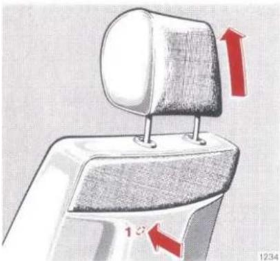
natural_image
Diagram of a mechanical component with red arrows indicating direction, no text or symbols presentSafety Headrests on the Front Seats
Detaching headrests:
Set headrest to uppermost position.
Depress arrester release button (1) to be felt under the seat back covering material and pull up headrest quickly, holding it by the LH headrest post (viewed in driving direction). Then pull out headrest completely with both hands.
The arrester release button (1) is located below the LH headrest post on both front seats.
Attaching headrests:
Attach the headrests in the same position as on removal. To do so, check if headrest is in the uppermost position (electrically adjustable headrest: depress top portion of switch for approximately 5 seconds; manually adjustable headrest: pull out handwheel and turn it to the rear to the stop).
Then install headrest, pressing it downward to the stop and then adjust.
Note:
For safety reasons we recommend you only to drive with the headrests installed.

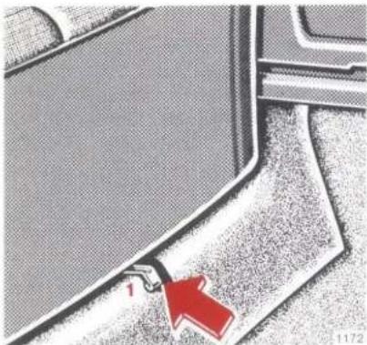
natural_image
Close-up of a mechanical component with a red arrow pointing to a small feature labeled '1' (no text or symbols beyond the label)Rear Seat Cushion
Removal: Depress release button 1 (left and right) and lift rear seat cushion by front end.
To install, push rear end of rear seat cushion under rear seat back as far as it will go, press down front section onto the support and allow to engage.
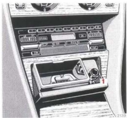
natural_image
Interior view of a car air conditioner unit with control panel and vent slots (no visible text or labels)Ashtrays
Removal, front
Tap on cover plate. The ashtray opens automatically. Push sliding knob 1 to the right. The tray will pop out a little.
Installation:
Position insert and press downwards until engaged.
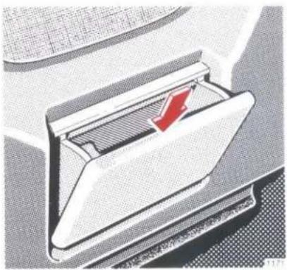
natural_image
Diagram of a computer mouse with a red arrow indicating the handle (no text or symbols present)Removal, rear:
Push the ashtray down while opening and remove.
Installation:
Set the ashtray in position accurately and push in.
Fire Extinguisher
The fire extinguisher is mounted in front of the driver's seat. It must be recharged after each use and inspected every 1 - 2 years.
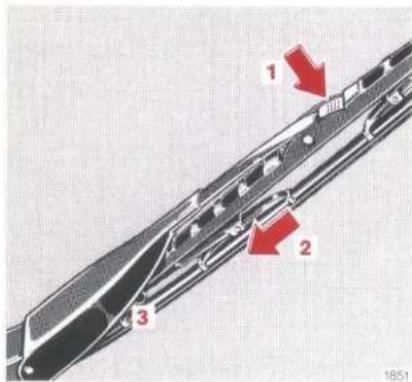
text_image
1 2 3 1851Changing Wiper Blades
Take key out of steering lock before changing wiper blade.
Windscreen Wiper Blade
Removal:
Pull wiper arm forwards. Press safety button (1), push blade down (2) and remove.
Fitting:
Press safety button on new wiper blade. Position wiper blade between lugs (3) on wiper arm and slip into wiper arm end. Push safety button up until it clips in place.
Note:
Do not open bonnet when wiper arm is pulled out.
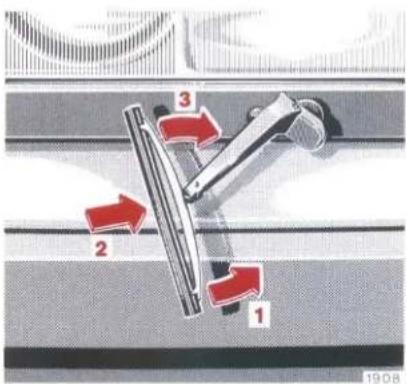
text_image
1 2 3 1908Wiper Blades for Headlamp Cleaning System
Removal:
Pull wiper arm outwards and swivel wiper blade (1) until it disengages from the wiper arm.
Fitting:
Position wiper blade at right angles to the wiper arm (2) and pivot (3) until it engages.

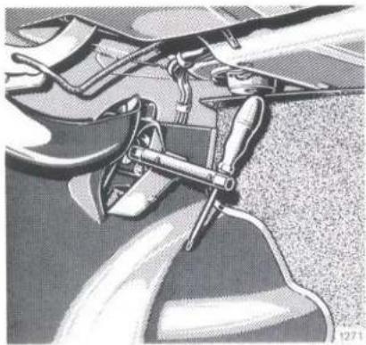
natural_image
Illustration of a mechanical device with attached components, no visible text or symbolsEmergency Operation of Pop-up/Sliding Roof
If the electrical drive fails, the pop-up/sliding roof can also be operated manually.
For this purpose, a hexagon is provided on the drive motor which is accommodated on the LH side in the boot behind the side panel covering. Open flap in the side panel covering, slip socket wrench (vehicle tools) onto hexagon and turn to move the pop-up/sliding roof in the desired direction.
Closing the pop-up/sliding roof: Sliding position: rotate clockwise. Pop-up position: rotate anti-clockwise.
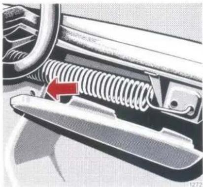
natural_image
Close-up of a car's side panel showing spring and handle mechanism (no text or symbols)Emergency Release of Fuel Filler Flap
Saloon:
Pull away panel on right of boot slightly. Pull emergency release knob and open the fuel filler flap at the same time.
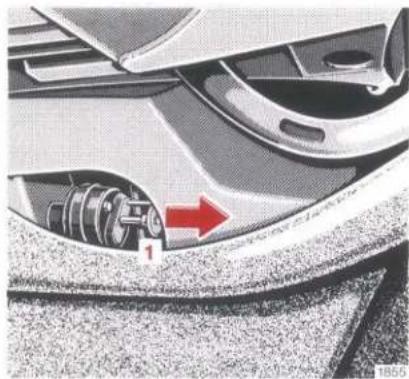
natural_image
Close-up of a car's front wheel and dashboard with a red arrow pointing to the wheel (no text or symbols visible)Coupé:
Pull out emergency release knob (1) behind the right hand panel in the boot and open the fuel filler flap at the same time.
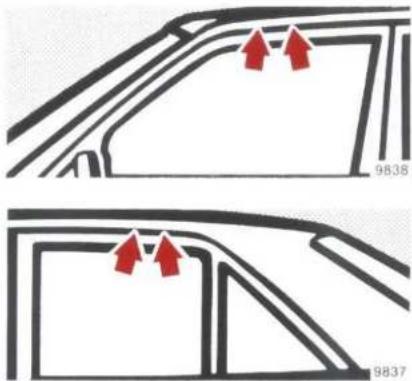
natural_image
Two identical car door diagrams with red arrows pointing to the front panel (no text or symbols)Roof Rack
In order to prevent damage to the vehicle, only use roof racks tested and recommended by us. Follow manufacturer's fitting instructions.
Saloon: Only fasten the rack between the two markings on the roof frame which are visible when the doors are opened.
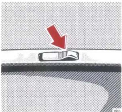
natural_image
Diagram showing a car on a road with a red arrow indicating downward motion (no text or symbols)Coupé:
Press open the four flaps in the water deflectors. Place rack in position and turn screws in the threaded bushes.
text_image
5 8 7 1 2 3 1506200, 200 E, 230 E, 230 CE
flowchart
graph TD
    A["1"] --> B["2"]
    B --> C["3"]
    C --> D["4"]
    D --> E["5"]
    E --> F["6"]
    F --> G["7"]
    G --> H["8"]
    H --> A
    style A fill:#f9f,stroke:#333
    style B fill:#f9f,stroke:#333
    style C fill:#f9f,stroke:#333
    style D fill:#f9f,stroke:#333
    style E fill:#f9f,stroke:#333
    style F fill:#f9f,stroke:#333
    style G fill:#f9f,stroke:#333
    style H fill:#f9f,stroke:#333
260 E, 300 E, 300 CE 260 E 4MATIC, 300 E 4MATIC
Operation Diagram of Poly-V-belt
1 Idler pulley with tensioning device
2 Crankshaft
3 Refrigerant compressor
4 Fan
5 Alternator
6 Guide pulley
7 Power steering pump
8 200, 200 E, 230 E, 230 CE: Fan, coolant pump
260 E, 300 E, 300 CE, 260 E 4MATIC, 300 E 4MATIC: Coolant pump
Install the poly-V-belt by starting at the idler pulley (1) and proceed with the other pulleys in numerical order.
For poly-V-belt dimensions refer to "Technical Data".
Spare Parts Service
All MERCEDES-BENZ service stations store the MERCEDES-BENZ original spare parts required for maintenance and repair work. Besides this bases are provided all over the globe intended to ensure the rapid supply of MERCEDES-BENZ original spare parts. More than 300 000 different spare parts, even for rather old vehicle models, are furthermore stocked in the central plant warehouses.
We guarantee maximum operational efficiency and reliability as well as optimum retention of the vehicle value when MERCEDES-BENZ original spare parts are installed, as they are subjected to most severe quality inspections. Each part has been specifically developed, manufactured or selected for and adapted to MERCEDES-BENZ vehicles.
For this reason, only MERCEDES-BENZ original spare parts should be installed.
In the Federal Republic of Germany as well as in numerous other countries certain parts are authorized to be installed or attached only if they comply with current legislation.
This prerequisite is definitely met by original MERCEDES-BENZ replacement parts. If other parts are used, the operating permit may expire.

| 2017 | 2016 | |||
| 金额 | 占总资产比例(%) | 金额 | 占总资产比例(%) | |
| 一、营业收入 | 3,584,968.00 | 69.99 | 3,584,968.00 | 69.99 |
| 二、营业成本 | 3,418,817.00 | 66.99 | 3,418,817.00 | 66.99 |
| 三、营业利润 | -1,425,325.00 | 15.22 | -1,425,325.00 | 15.22 |
| 四、净利润 | -1,425,325.00 | 15.22 | -1,425,325.00 | 15.22 |
Technical Data Service Products
Brake Fluid 129
Coolant 130
Engine Oils 129
Fuels 129
Identification Plates 106
Service Products - Capacities 125
Technical Data
200 107
200 E 109
230 E 111
230 CE 113
260 E 115
260 E 4MATIC 117
300 E 119
300 CE 121
300 E 4MATIC 123
Vehicle Data Cards 106

Identification Plates
When ordering spare parts, please quote vehicle identification and engine numbers.
1 Identification plate
2 Vehicle identification no.
3 Body No., Paint code No.
4 Engine No. (260 E/4MATIC, 300 E/CE/4MATIC front, RH side)
text_image
Technical diagram of a Mercedes-Benz sedan showing engine compartment with numbered parts for identificationVehicle Data Cards
The vehicle data cards bear all the important data relating to your vehicle.
Data card No. 1 – sent through the mail – containing information concerning the key number should not be left in the vehicle under any circumstances so as to permit you to request a replacement key from your MERCEDES-BENZ service station in case the key is lost.
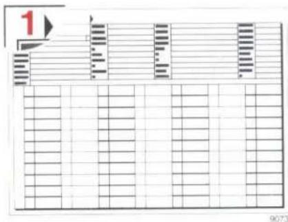
text_image
1 9073Data card no. 2 gives no key number and is kept in the maintenance booklet. Presenting this card to the service station will facilitate the processing of the order.
Technical Data 200
| Type | 200 (124 020)1 |
Engine
| Engine | 102 |
| Work cycle | 4-cycle carburetor |
| No. of cylinders | 4 |
| Bore | 89 mm |
| Stroke | 80.2 mm |
| Total piston displacement | 1996 cm^3 |
| Compression ratio | 9.1 |
| Nominal power rating2 according to 80/1269/EC | 80 kW at 5200/min |
| Nominal torque according to 80/1269/EC | 170 Nm at 2500/min |
| Max. engine speed | 6000/min |
| Firing order | 1 - 3 - 4 - 2 |
| Fuel consumption Engine oil consumption | see “Driving” |
| Poly-V-belt Vehicles equipped with air conditioner or automatic climate control | 1885 mm |
| 1980 mm |
Disk Wheels - Tyres
| Disk wheels | 6 J x 15 H 2 |
| Indentation depth | 49 mm |
| Summer tyres: | |
| Radial-ply tyres (tubeless) | 185/65 R 15 87 H |
| Winter tyres: | |
| Radial-ply tyres (tubeless) | 185/65 R 15 87 T M + S |
Electrical System
| Alternator | 14 V/55 A |
| Starter motor | 12 V/1.4 kW |
| Battery | 12 V/62 Ah |
| Spark plugs | Beru 14 K-7 DUBeru 14 K-7 DUOBosch H 7 DCBosch H 7 DCOChampion S 9 YCCampion S 9 YCC |
1 The technical data only apply to standard vehicles. Consult a MERCEDES-BENZ service station for the corresponding data for all special bodies and optional extras.
^2 The stated output is the power effectively available at the clutch, since all auxiliary requirements have already been deducted.
Technical Data 200
Main Dimensions
| Overall vehicle length | 4740 mm |
| Overall vehicle width | 1740 mm |
| Overall vehicle height | 1440 mm |
| Wheelbase | 2800 mm |
| Track, front | 1497 mm |
| Track, rear | 1488 mm |
Weights
| Vehicle weight ^3 | 1280 kg |
| Gross vehicle weight | 1800 kg |
| Permissible axle load, front | 845 kg |
| Permissible axle load, rear | 955 kg |
| Roof load max. | 100 kg |
| Boot load max. | 100 kg |
| Permissible trailer load: | |
| Trailer, unbraked | 675 kg |
| Trailer, braked | 1500 kg |
| Permissible drawbar load on the trailer coupling | 75 kg |
Speeds
Top speeds (km/h)
Manual and automatic transmission
| 4-speed | 5-speed | Automatic | |
| 1st gear | 54 | 54 | 46 |
| 2nd gear | 97 | 97 | 86 |
| 3rd gear | 152 | 152 | 138 |
| 4th gear approx. | 187 | 187 | 182 |
| 5th gear approx. | — | 180 | — |
Gradeability
Vehicle loaded with 2 persons
Manual and automatic transmission
| 4-speed | 5-speed | Automatic | |
| 1st gear^4 | 44% | 44% | 44% |
| 2nd gear | 26% | 26% | 35% |
| 3rd gear | 15% | 15% | 18% |
| 4th gear | 10% | 10% | 9% |
| 5th gear | — | 6% | — |
^3 Curb weight according to DIN 70020 for basic version vehicles. Optional extras increase this value and consequently decrease the payload.
^4 Achievable on roads offering good traction. (Gradeability from the standstill with 1500 kg trailer load and GVW: 13 % with manual transmission; at least 20 % with automatic transmission.)
Technical Data 200 E
| Type | 200 E (124 021) ^1 |
| Engine | |
| Engine | 102 |
| Work cycle | 4-cycle carburetor |
| No. of cylinders | 4 |
| Bore | 89 mm |
| Stroke | 80.2 mm |
| Total piston displacement | 1996 cm^3 |
| Compression ratio | 9.1 |
| Nominal power rating ^2 according to 80/1269/EC | 90 kW at 5200/min |
| Nominal torque accordingto 80/1269/EC | 178 Nm at 3500/min |
| Max. engine speed | 6000/min |
| Firing order | 1 - 3 - 4 - 2 |
| Fuel consumptionEngine oil consumption | see “Driving” |
| Poly-V-belt | 1885 mm |
| Vehicles equipped with airconditioner or automaticclimate control | 1980 mm |
Disk Wheels - Tyres
| Disk wheels | 6 J x 15 H 2 |
| Indentation depth | 49 mm |
| Summer tyres: | |
| Radial-ply tyres (tubeless) | 185/65 R 15 87 H |
| Winter tyres: | |
| Radial-ply tyres (tubeless) | 185/65 R 15 87 T M + S |
Electrical System
| Alternator | 14 V/55 A |
| Starter motor | 12 V/1.4 kW |
| Battery | 12 V/62 Ah |
| Spark plugs | Beru 14 K-7 DUBeru 14 K-7 DUOBosch H 7 DCBosch H 7 DCOChampion S 9 YCCampion S 9 YCC |
^1 The technical data only apply to standard vehicles. Consult a MERCEDES-BENZ service station for the corresponding data for all special bodies and optional extras.
^2 The stated output is the power effectively available at the clutch, since all auxiliary requirements have already been deducted.
Technical Data 200 E
Main Dimensions
| Overall vehicle length | 4740 mm |
| Overall vehicle width | 1740 mm |
| Overall vehicle height | 1440 mm |
| Wheelbase | 2800 mm |
| Track, front | 1497 mm |
| Track, rear | 1488 mm |
Weights
| Vehicle weight ^3 | 1290 kg |
| Gross vehicle weight | 1810 kg |
| Permissible axle load, front | 850 kg |
| Permissible axle load, rear | 960 kg |
| Roof load max. | 100 kg |
| Boot load max. | 100 kg |
| Permissible trailer load: | |
| Trailer, unbraked | 680 kg |
| Trailer, braked | 1500 kg |
| Permissible drawbar load on the trailer coupling | 75 kg |
Speeds
Top speeds (km/h)
Manual and automatic transmission
| 4-speed | 5-speed | Automatic | |
| 1st gear | 54 | 54 | 46 |
| 2nd gear | 97 | 97 | 86 |
| 3rd gear | 152 | 152 | 138 |
| 4th gear approx. | 195 | 195 | 190 |
| 5th gear approx. | — | 188 | — |
Gradeability
Vehicle loaded with 2 persons
Manual and automatic transmission
| 4-speed | 5-speed | Automatic | |
| 1st gear^4 | 44% | 44% | 44% |
| 2nd gear | 25% | 25% | 34% |
| 3rd gear | 14% | 14% | 17% |
| 4th gear | 9% | 9% | 8.5% |
| 5th gear | — | 6% | — |
3 Curb weight according to DIN 70020 for basic version vehicles. Optional extras increase this value and consequently decrease the payload.
^4 Achievable on roads offering good traction. (Gradeability from the standstill with 1500 kg trailer load and GVW: 13% with manual transmission; at least 20% with automatic transmission.)
Technical Data 230 E
| Type | 230 E (124 023) ^1 |
| Engine | |
| Engine | 102 |
| Work cycle | 4-cycle fuel injection |
| No. of cylinders | 4 |
| Bore | 95.50 mm |
| Stroke | 80.2 mm |
| Total piston displacement | 2298 cm^3 |
| Compression ratio | 9 |
| Nominal power rating ^2 according to 80/1269/EC | 100 kW at 5100/min |
| Nominal torque accordingto 80/1269/EC | 205 Nm at 3500/min |
| Max. engine speed | 6000/min |
| Firing order | 1-3-4-2 |
| Fuel consumptionEngine oil consumption | see “Driving” |
| Poly-V-belt | 1885 mm |
| Vehicles equipped with airconditioner or automaticclimate control | 1980 mm |
Disk Wheels - Tyres
| Disk wheels | 6 12 J x 15 H 2 |
| Indentation depth | 49 mm |
| Summer tyres: | |
| Radial-ply tyres (tubeless) | 195/65 R 15 91 H |
| Winter tyres: | |
| Radial-ply tyres (tubeless) | 195/65 R 15 91 T M + S |
Electrical System
| Alternator | 14 V/55 A |
| Starter motor | 12 V/1.4 kW |
| Battery | 12 V/62 Ah |
| Spark plugs | Beru 14 K-7 DUBeru 14 K-7 DUOBosch H 7 DCBosch H 7 DCOChampion S 9 YCCampion S 9 YCC |
1 The technical data only apply to standard vehicles. Consult a MERCEDES-BENZ service station for the corresponding data for all special bodies and optional extras.
2 The stated output is the power effectively available at the clutch, since all auxiliary requirements have already been deducted.
Technical Data 230 E
Main Dimensions
| Overall vehicle length | 4740 mm |
| Overall vehicle width | 1740 mm |
| Overall vehicle height | 1446 mm |
| Wheelbase | 2800 mm |
| Track, front | 1497 mm |
| Track, rear | 1488 mm |
Weights
| Vehicle weight ^3 | 1310 kg |
| Gross vehicle weight | 1830 kg |
| Permissible axle load, front | 855 kg |
| Permissible axle load, rear | 975 kg |
| Roof load max. | 100 kg |
| Boot load max. | 100 kg |
| Permissible trailer load: | |
| Trailer, unbraked | 690 kg |
| Trailer, braked | 1500 kg |
| Permissible drawbar load on the trailer coupling | 75 kg |
Speeds
Top speeds (km/h)
Manual and automatic transmission
| 4-speed | 5-speed | Automatic | |
| 1st gear | 57 | 57 | 48 |
| 2nd gear | 102 | 102 | 91 |
| 3rd gear | 162 | 162 | 147 |
| 4th gear approx. | 203 | 203 | 198 |
| 5th gear approx. | — | 198 | — |
Gradeability
Vehicle loaded with 2 persons
Manual and automatic transmission
| 4-speed | 5-speed | Automatic | |
| 1st gear^4 | 44% | 44% | 44% |
| 2nd gear | 28% | 28% | 42% |
| 3rd gear | 16% | 16% | 20% |
| 4th gear | 10.5% | 10.5% | 10% |
| 5th gear | — | 7% | — |
3 Curb weight according to DIN 70020 for basic version vehicles. Optional extras increase this value and consequently decrease the payload.
^4 Achievable on roads offering good traction. (Gradeability from the standstill with 1500 kg trailer load and GVW: 15 % with manual transmission; at least 20 % with automatic transmission.)
Technical Data 230 CE
| Type | 230 CE (124 043)1 |
Engine
| Engine | 102 |
| Work cycle | 4-cycle fuel injection |
| No. of cylinders | 4 |
| Bore | 95.50 mm |
| Stroke | 80.2 mm |
| Total piston displacement | 2298 cm^3 |
| Compression ratio | 9 |
| Nominal power rating ^2 according to 80/1269/EC | 100 kW at 5100/min |
| Nominal torque accordingto 80/1269/EC | 205 Nm at 3500/min |
| Max. engine speed | 6000/min |
| Firing order | 1-3-4-2 |
| Fuel consumptionEngine oil consumption | see “Driving” |
| Poly-V-belt | 1885 mm |
| Vehicles equipped with airconditioner or automaticclimate control | 1980 mm |
Disk Wheels - Tyres
| Disk wheels | 6 12 J x 15 H 2 |
| Indentation depth | 49 mm |
| Summer tyres: | |
| Radial-ply tyres (tubeless) | 195/65 R 15 91 H |
| Winter tyres: | |
| Radial-ply tyres (tubeless) | 195/65 R 15 91 T M + S |
Electrical System
| Alternator | 14 V/55 A |
| Starter motor | 12 V/1.4 kW |
| Battery | 12 V/62 Ah |
| Spark plugs | Beru 14 K-7 DUBeru 14 K-7 DUOBosch H 7 DCBosch H 7 DCOChampion S 9 YCCampion S 9 YCC |
1 The technical data only apply to standard vehicles. Consult a MERCEDES-BENZ service station for the corresponding data for all special bodies and optional extras.
^2 The stated output is the power effectively available at the clutch, since all auxiliary requirements have already been deducted.
Technical Data 230 CE
Main Dimensions
| Overall vehicle length | 4655 mm |
| Overall vehicle width | 1740 mm |
| Overall vehicle height | 1410 mm |
| Wheelbase | 2715 mm |
| Track, front | 1497 mm |
| Track, rear | 1488 mm |
Weights
| Vehicle weight ^3 | 1340 kg |
| Gross vehicle weight | 1790 kg |
| Permissible axle load, front | 855 kg |
| Permissible axle load, rear | 935 kg |
| Roof load max. | 100 kg |
| Boot load max. | 100 kg |
| Permissible trailer load: | |
| Trailer, unbraked | 705 kg |
| Trailer, braked | 1500 kg |
| Permissible drawbar load on the trailer coupling | 75 kg |
Speeds
Top speeds
| Manual transmission | Automatic transmission | |
| 1st gear | 57 km/h | 48 km/h |
| 2nd gear | 102 km/h | 91 km/h |
| 3rd gear | 162 km/h | 147 km/h |
| 4th gear approx. | 203 km/h | 198 km/h |
| 5th gear approx. | 198 km/h | — |
Gradeability
Vehicle loaded with 2 persons
| Manual transmission | Automatic transmission | |
| 1st gear^4 | 44 % | 44 % |
| 2nd gear | 27 % | 41 % |
| 3rd gear | 15 % | 19 % |
| 4th gear | 10 % | 9 % |
| 5th gear | 6.5 % | — |
3 Curb weight according to DIN 70020 for basic version vehicles. Optional extras increase this value and consequently decrease the payload.
4 Achievable on roads offering good traction. (Gradeability from the standstill with 1500 kg trailer load and GVW: 15% with manual transmission; at least 20% with automatic transmission.)
Technical Data 260 E
| Type | 260 E (124 026) ^1 |
| Engine | |
| Engine | 103 |
| Work cycle | 4-cycle fuel injection |
| No. of cylinders | 6 |
| Bore | 82.90 mm |
| Stroke | 80.2 mm |
| Total piston displacement | 2597 cm^3 |
| Compression ratio | 9.2 |
| Nominal power rating ^2 according to 80/1269/EC | 122 kW at 5800/min |
| Nominal torque accordingto 80/1269/EC | 228 Nm at 4600/min |
| Max. engine speed | 6200/min |
| Firing order | 1 - 5 - 3 - 6 - 2 - 4 |
| Fuel consumptionEngine oil consumption | see “Driving” |
| Poly-V-belt | 2170 mm |
| Vehicles equipped with airconditioner or automaticclimate control | 2255 mm |
Disk Wheels – Tyres
| Disk wheels | 6 12 J x 15 H 2 |
| Indentation depth | 49 mm |
| Summer tyres: | |
| Radial-ply tyres (tubeless) | 195/65 VR 15 |
| Winter tyres: | |
| Radial-ply tyres (tubeless) | 195/65 R 15 91 TM + S |
Electrical System
| Alternator | 14 V/70 A |
| Starter motor | 12 V/1.7 kW |
| Battery | 12 V/62 Ah |
| Spark plugs | Beru 14 K-8 DUBeru 14 K-8 DUOBosch H 8 DCBosch H 8 DCOChampion S 10 YCC |
1 The technical data only apply to standard vehicles. Consult a MERCEDES-BENZ service station for the corresponding data for all special bodies and optional extras.
^2 The stated output is the power effectively available at the clutch, since all auxiliary requirements have already been deducted.
Technical Data 260 E
Main Dimensions
| Overall vehicle length | 4740 mm |
| Overall vehicle width | 1740 mm |
| Overall vehicle height | 1446 mm |
| Wheelbase | 2800 mm |
| Track, front | 1497 mm |
| Track, rear | 1488 mm |
Weights
| Vehicle weight ^3 | 1370 kg |
| Gross vehicle weight | 1890 kg |
| Permissible axle load, front | 905 kg |
| Permissible axle load, rear | 985 kg |
| Roof load max. | 100 kg |
| Boot load max. | 100 kg |
| Permissible trailer load: | |
| Trailer, unbraked | 720 kg |
| Trailer, braked | 1500 kg |
| Permissible drawbar load on the trailer coupling | 75 kg |
Speeds
Top speeds
| Manual transmission | Automatic transmission | |
| 1st gear | 60 km/h | 54 km/h |
| 2nd gear | 105 km/h | 94 km/h |
| 3rd gear | 167 km/h | 153 km/h |
| 4th gear approx. | 218 km/h | 213 km/h |
| 5th gear approx. | 213 km/h | — |
Gradeability
Vehicle loaded with 2 persons
| Manual transmission | Automatic transmission | |
| 1st gear^4 | 43 % | 43 % |
| 2nd gear | 31 % | 42 % |
| 3rd gear | 17 % | 20 % |
| 4th gear | 11 % | 10 % |
| 5th gear | 8 % | — |
^3 Curb weight according to DIN 70020 for basic version vehicles. Optional extras increase this value and consequently decrease the payload.
^4 Achievable on roads offering good traction. (Gradeability from the standstill with 1500 kg trailer load and GVW: 15% with manual transmission; at least 20% with automatic transmission.)
Technical Data 260 E 4MATIC
| Type | 260 E 4MATIC (124 226)1 |
Engine
| Engine | 103 |
| Work cycle | 4-cycle fuel injection |
| No. of cylinders | 6 |
| Bore | 82.90 mm |
| Stroke | 80.2 mm |
| Total piston displacement | 2597 cm ^3 |
| Compression ratio | 9.2 |
| Nominal power rating ^2 according to 80/1269/EC | 122 kW at 5800/min |
| Nominal torque accordingto 80/1269/EC | 228 Nm at 4600/min |
| Max. engine speed | 6200/min |
| Firing order | 1-5-3-6-2-4 |
| Fuel consumptionEngine oil consumption | see “Driving” |
| Poly-V-belt | 2170 mm |
| Vehicles equipped with airconditioner or automaticclimate control | 2255 mm |
Disk Wheels - Tyres
| Disk wheels | 6 12 J x 15 H 2 |
| Indentation depth | 49 mm |
| Summer tyres: | |
| Radial-ply tyres (tubeless) | 195/65 VR 15 |
| Winter tyres: | |
| Radial-ply tyres (tubeless) | 195/65 R 15 91 TM + S |
Electrical System
| Alternator | 14 V/70 A |
| Starter motor | 12 V/1.7 kW |
| Battery | 12 V/62 Ah |
| Spark plugs | Beru 14 K-8 DUBeru 14 K-8 DUOBosch H 8 DCBosch H 8 DCOChampion S 10 YCC |
1 The technical data only apply to standard vehicles. Consult a MERCEDES-BENZ service station for the corresponding data for all special bodies and optional extras.
^2 The stated output is the power effectively available at the clutch, since all auxiliary requirements have already been deducted.
Technical Data 260 E 4MATIC
Main Dimensions
| Overall vehicle length | 4740 mm |
| Overall vehicle width | 1740 mm |
| Overall vehicle height | 1451 mm |
| Wheelbase | 2800 mm |
| Track, front | 1497 mm |
| Track, rear | 1485 mm |
Weights
| Vehicle weight ^3 | 1490 kg |
| Gross vehicle weight | 2010 kg |
| Permissible axle load, front | 995 kg |
| Permissible axle load, rear | 1015 kg |
| Roof load max. | 100 kg |
| Boot load max. | 100 kg |
| Permissible trailer load: | |
| Trailer, unbraked | 750 kg |
| Trailer, braked | 1500 kg |
| Permissible drawbar load on the trailer coupling | 75 kg |
Speeds
Top speeds
| Manual transmission | Automatic transmission | |
| 1st gear | 57 km/h | 59 km/h |
| 2nd gear | 100 km/h | 100 km/h |
| 3rd gear | 156 km/h | 155 km/h |
| 4th gear approx. | 210 km/h | 210 km/h |
| 5th gear approx. | 210 km/h | — |
Gradeability
Vehicle loaded with 2 persons
| Manual transmission | Automatic transmission | |
| 1st gear^4 | 61 % | 72 % |
| 2nd gear | 29 % | 31 % |
| 3rd gear | 16 % | 16 % |
| 4th gear | 10 % | 9 % |
| 5th gear | 7 % | — |
3 Curb weight according to DIN 70020 for basic version vehicles. Optional extras increase this value and consequently decrease the payload.
^4 Achievable on roads offering good traction. (Gradeability from the standstill with 1500 kg trailer load and GVW; 15 % with manual transmission; at least 20 % with automatic transmission.)
Technical Data 300 E
| Type | 300 E (124 030) ^1 |
| Engine | |
| Engine | 103 |
| Work cycle | 4-cycle fuel injection |
| No. of cylinders | 6 |
| Bore | 88.50 mm |
| Stroke | 80.2 mm |
| Total piston displacement | 2960 cm^3 |
| Compression ratio | 9.2 |
| Nominal power rating ^2 according to 80/1269/EC | 138 kW at 5700/min |
| Nominal torque accordingto 80/1269/EC | 260 Nm at 4400/min |
| Max. engine speed | 6200/min |
| Firing order | 1 - 5 - 3 - 6 - 2 - 4 |
| Fuel consumptionEngine oil consumption | see “Driving” |
| Poly-V-belt | 2170 mm |
| Vehicles equipped with airconditioner or automaticclimate control | 2255 mm |
Disk Wheels - Tyres
| Disk wheels | 6 12 J x 15 H 2 |
| Indentation depth | 49 mm |
| Summer tyres: | |
| Radial-ply tyres (tubeless) | 195/65 VR 15 |
| Winter tyres: | |
| Radial-ply tyres (tubeless) | 195/65 R 15 91 TM + S |
Electrical System
| Alternator | 14 V/70 A |
| Starter motor | 12 V/1.7 kW |
| Battery | 12 V/62 Ah |
| Spark plugs | Beru 14 K-8 DUBeru 14 K-8 DUOBosch H 8 DCBosch H 8 DCOChampion S 10 YCC |
1 The technical data only apply to standard vehicles. Consult a MERCEDES-BENZ service station for the corresponding data for all special bodies and optional extras.
2 The stated output is the power effectively available at the clutch, since all auxiliary requirements have already been deducted.
Technical Data 300 E
Main Dimensions
| Overall vehicle length | 4740 mm |
| Overall vehicle width | 1740 mm |
| Overall vehicle height | 1446 mm |
| Wheelbase | 2800 mm |
| Track, front | 1497 mm |
| Track, rear | 1488 mm |
Weights
| Vehicle weight ^3 | 1370 kg |
| Gross vehicle weight | 1890 kg |
| Permissible axle load, front | 905 kg |
| Permissible axle load, rear | 985 kg |
| Roof load max. | 100 kg |
| Boot load max. | 100 kg |
| Permissible trailer load: | |
| Trailer, unbraked | 720 kg |
| Trailer, braked | 1500 kg |
| Permissible drawbar load on the trailer coupling | 75 kg |
Speeds
Top speeds
| Manual transmission | Automatic transmission | |
| 1st gear | 64 km/h | 63 km/h |
| 2nd gear | 113 km/h | 107 km/h |
| 3rd gear | 177 km/h | 166 km/h |
| 4th gear approx. | 228 km/h | 223 km/h |
| 5th gear approx. | 223 km/h | — |
Gradeability
Vehicle loaded with 2 persons
| Manual transmission | Automatic transmission | |
| 1st gear^4 | 43 % | 43 % |
| 2nd gear | 33 % | 40 % |
| 3rd gear | 18 % | 20 % |
| 4th gear | 12 % | 11 % |
| 5th gear | 8.5 % | — |
^3 Curb weight according to DIN 70020 for basic version vehicles. Optional extras increase this value and consequently decrease the payload.
^4 Achievable on roads offering good traction. (Gradeability from the standstill with 1500 kg trailer load and GVW: 15% with manual transmission; at least 20% with automatic transmission.)
Technical Data 300 CE
| Type | 300 CE (124 050) ^1 |
| Engine | |
| Engine | 103 |
| Work cycle | 4-cycle fuel injection |
| No. of cylinders | 6 |
| Bore | 88.50 mm |
| Stroke | 80.2 mm |
| Total piston displacement | 2960 cm^3 |
| Compression ratio | 9.2 |
| Nominal power rating ^2 according to 80/1269/EC | 138 kW at 5700/min |
| Nominal torque accordingto 80/1269/EC | 260 Nm at 4400/min |
| Max. engine speed | 6200/min |
| Firing order | 1-5-3-6-2-4 |
| Fuel consumptionEngine oil consumption | see “Driving” |
| Poly-V-belt | 2170 mm |
| Vehicles equipped with airconditioner or automaticclimate control | 2255 mm |
Disk Wheels - Tyres
| Disk wheels | 6 12 J x 15 H 2 |
| Indentation depth | 49 mm |
| Summer tyres: | |
| Radial-ply tyres (tubeless) | 195/65 VR 15 |
| Winter tyres: | |
| Radial-ply tyres (tubeless) | 195/65 R 15 91 T M + S |
Electrical System
| Alternator | 14 V/70 A |
| Starter motor | 12 V/1.7 kW |
| Battery | 12 V/62 Ah |
| Spark plugs | Beru 14 K-8 DUBeru 14 K-8 DUOBosch H 8 DCBosch H 8 DCOChampion S 10 YCC |
1 The technical data only apply to standard vehicles. Consult a MERCEDES-BENZ service station for the corresponding data for all special bodies and optional extras.
^2 The stated output is the power effectively available at the clutch, since all auxiliary requirements have already been deducted.
Technical Data 300 CE
Main Dimensions
| Overall vehicle length | 4655 mm |
| Overall vehicle width | 1740 mm |
| Overall vehicle height | 1410 mm |
| Wheelbase | 2715 mm |
| Track, front | 1497 mm |
| Track, rear | 1488 mm |
Weights
| Vehicle weight ^3 | 1390 kg |
| Gross vehicle weight | 1840 kg |
| Permissible axle load, front | 900 kg |
| Permissible axle load, rear | 940 kg |
| Roof load max. | 100 kg |
| Boot load max. | 100 kg |
| Permissible trailer load: | |
| Trailer, unbraked | 730 kg |
| Trailer, braked | 1500 kg |
| Permissible drawbar load on the trailer coupling | 75 kg |
Speeds
Top speeds
| Manual transmission | Automatic transmission | |
| 1st gear | 64 km/h | 63 km/h |
| 2nd gear | 113 km/h | 107 km/h |
| 3rd gear | 177 km/h | 166 km/h |
| 4th gear approx. | 228 km/h | 223 km/h |
| 5th gear approx. | 223 km/h | — |
Gradeability
Vehicle loaded with 2 persons
| Manual transmission | Automatic transmission | |
| 1st gear^4 | 43 % | 43 % |
| 2nd gear | 32 % | 40 % |
| 3rd gear | 17 % | 20 % |
| 4th gear | 11 % | 11 % |
| 5th gear | 8 % | — |
3 Curb weight according to DIN 70020 for basic version vehicles. Optional extras increase this value and consequently decrease the payload.
^4 Achievable on roads offering good traction. (Gradeability from the standstill with 1500 kg trailer load and GVW: 17% with manual transmission; at least 20% with automatic transmission.)
Technical Data 300 E 4MATIC
| Type | 300 E 4MATIC (124 230)1 |
Engine
| Engine | 103 |
| Work cycle | 4-cycle fuel injection |
| No. of cylinders | 6 |
| Bore | 88.50 mm |
| Stroke | 80.2 mm |
| Total piston displacement | 2960 cm ^3 |
| Compression ratio | 9.2 |
| Nominal power rating ^2 according to 80/1269/EC | 138 kW at 5700/min |
| Nominal torque accordingto 80/1269/EC | 260 Nm at 4400/min |
| Max. engine speed | 6200/min |
| Firing order | 1-5-3-6-2-4 |
| Fuel consumption | see “Driving” |
| Engine oil consumption | |
| Poly-V-belt | 2170 mm |
| Vehicles equipped with airconditioner or automaticclimate control | 2255 mm |
Disk Wheels - Tyres
| Disk wheels | 6 12 J x 15 H 2 |
| Indentation depth | 49 mm |
| Summer tyres: | |
| Radial-ply tyres (tubeless) | 195/65 VR 15 |
| Winter tyres: | |
| Radial-ply tyres (tubeless) | 195/65 R 15 91 TM + S |
Electrical System
| Alternator | 14 V/70 A |
| Starter motor | 12 V/1.7 kW |
| Battery | 12 V/62 Ah |
| Spark plugs | Beru 14 K-8 DUBeru 14 K-8 DUOBosch H 8 DCBosch H 8 DCOChampion S 10 YCC |
1 The technical data only apply to standard vehicles. Consult a MERCEDES-BENZ service station for the corresponding data for all special bodies and optional extras.
^2 The stated output is the power effectively available at the clutch, since all auxiliary requirements have already been deducted.
Technical Data 300 E 4MATIC
Main Dimensions
| Overall vehicle length | 4740 mm |
| Overall vehicle width | 1740 mm |
| Overall vehicle height | 1451 mm |
| Wheelbase | 2800 mm |
| Track, front | 1497 mm |
| Track, rear | 1485 mm |
Weights
| Vehicle weight ^3 | 1490 kg |
| Gross vehicle weight | 2010 kg |
| Permissible axle load, front | 995 kg |
| Permissible axle load, rear | 1015 kg |
| Roof load max. | 100 kg |
| Boot load max. | 100 kg |
| Permissible trailer load: | |
| Trailer, unbraked | 750 kg |
| Trailer, braked | 1500 kg |
| Permissible drawbar load on the trailer coupling | 75 kg |
Speeds
Top speeds
| Manual transmission | Automatic transmission | |
| 1st gear | 60 km/h | 63 km/h |
| 2nd gear | 105 km/h | 107 km/h |
| 3rd gear | 167 km/h | 166 km/h |
| 4th gear approx. | 220 km/h | 220 km/h |
| 5th gear approx. | 220 km/h | — |
Gradeability
Vehicle loaded with 2 persons
| Manual transmission | Automatic transmission | |
| 1st gear^4 | 69 % | 78 % |
| 2nd gear | 32 % | 36 % |
| 3rd gear | 18 % | 19 % |
| 4th gear | 11 % | 10 % |
| 5th gear | 8 % | — |
3 Curb weight according to DIN 70020 for basic version vehicles. Optional extras increase this value and consequently decrease the payload.
^4 Achievable on roads offering good traction. (Gradeability from the standstill with 1500 kg trailer load and GVW: 17 % with manual transmission; at least 20 % with automatic transmission.)
Service Products - Capacities
Components and lubricants must match. Therefore, only tested and recommended brands must be used.
They are included in the MERCEDES-BENZ Specifications for Service Products. The corresponding sheet numbers are listed with the service products. All MERCEDES-BENZ service stations will advise you.
| Type | Capacity | Service product | ||
| Engine with oil filter | 200200 E230 E230 CE | 5 l | Recommended engine oil | |
| Ambient temp. | SAE grades | |||
| 260 E300 E300 CE | 6 l | 1 SAE 40 my be used if ambient temperatures constantly exceed +30 °C / 86 °F. | ||
| 260 E4MATIC300 E4MATIC | 6.5 l | |||
| Carburetor | 200 | approx. 30 cm ^3 | Automatic transmission fluid (ATF) Sheet no. 236.4 | |
| Manual four-speed transmission | 200 230 E200 E | 1.3 l | Automatic transmission fluid for manual transmission Sheet no. 236.2 | |
| Manual five-speed transmission | 200 260 E200 E 4MATIC230 E 300 E260 E 4MATIC300 E230 CE300 CE | 1.5 l | ||
| Automatic transmission | 200 200 E | Initial fill: 6.6 lFluid change: 5.5 l | Automatic transmission fluid for automatic transmission Sheet no. 236.4, 236.6 | |
| 230 E 230 CE260 E | Initial fill: 7.1 lFluid change: 6.0 l | |||
| 300 E 260 E300 CE 4MATIC300 E4MATIC | Initial fill: 7.3 lFluid change: 6.2 l | |||
| Transfer case | 260 E 300 E4MATIC 4MATIC | 0.7 l | ||
| Front axle | 1 l | Hypoid gear oil SAE 90, 85 W 90 Sheet no. 235 | ||
| Rear axle | 200 200 E | 0.7 l | ||
| 230 E 230 CE260 E 300 CE300 E | 1.1 l | |||
| 260 E 300 E4MATIC 4MATIC | 1.1 l | Hypoid gear oil SAE 90 for limited slip differential Sheet no. 235.3 | ||
| Rear axle with automatic locking differential (ASD) | 200 | 300 E | 1.1 l | Hypoid gear oil SAE 90 for limited slip differential Sheet no. 235.3 |
| 200 E | 230 CE | |||
| 230 E | 300 CE | |||
| 260 E | ||||
| Power steering | 200 | 300 CE | approx. 1 l | Automatic transmission fluid for power steering Sheet no. 236.3 |
| 200 E | 260 E | |||
| 230 E | 4MATIC | |||
| 260 E | 300 E | |||
| 300 E | 4MATIC | |||
| Level control ^1 | 230 CE | approx. 2 l | Hydraulic oil Sheet no. 343 | |
| Hydraulic system for automatic locking differential (ASD) ^2 | 200 | 300 E | ||
| 200 E | 230 CE | |||
| 230 E | 300 CE | |||
| 260 E | ||||
| Hydraulic system for 4MATIC ^2 | 260 E | 300 E | ||
| 4MATIC | 4MATIC | |||
| Front wheel bearings | 200 | 300 E | approx. 60 g each | High-temperature antifriction bearing grease Sheet no. 265.1 |
| 200 E | 230 CE | |||
| 230 E | 300 CE | |||
| 260 E | ||||
| Brake system and (with manual transmission) clutch | 200 | 300 CE | approx. 0.5 l | Brake fluid according Sheet no. 331.0 |
| 200 E | 260 E | |||
| 230 E | 4MATIC | |||
| 260 E | 300 E | |||
| 300 E | 4MATIC | |||
| 230 CE | ||||
^1 A single reservoir for level control and automatic locking differential (or 4MATIC).
^2 A single reservoir for automatic locking differential (or 4MATIC) and level control.
| Type | Capacity | Service product | ||
| Windscreen washer system | 200 | 260 E | approx. 5 l | Water plus MB windscreen washing detergent S for summer or W for winter |
| Windscreen washer system and headlamp cleaning system | 200 E | 4MATIC | ||
| 230 E | 300 E | Observe mixing ratio | ||
| 260 E | 4MATIC | Sheet no. 371 | ||
| Fuel tank including a reserve of | 300 E | approx. 70 l | Leaded premium fuels98 RON/88 MON minimum | |
| 230 CE | approx. 9 l | Unleaded premium fuels ^1) 95 RON/85 MON minimum | ||
| 300 CE | ||||
| Cooling system | 200 | approx. 8.5 l | CoolantSheet no. 310, 311, 325.1 | |
| 200 E | ||||
| 230 E | ||||
| 230 CE | ||||
| 260 E | 260 E | approx. 9 l | ||
| 300 E | 4MATIC | |||
| 300 CE | 300 E | |||
| 4MATIC | ||||
1) 230 E: For running the vehicle on unleaded premium fuel, have ignition timing adapted at a MERCEDES-BENZ service station.
Engine Oils
The suitability of the various engine oils is specially tested in our engines. For this reason, use only those engine oils which have been approved by our company. MERCEDES-BENZ service stations have all the information on approved brands.
Fuels
For knock-free operation the engines have to be run on fuels which have the following minimum octane ratings (measured according to research octane number = RON and motor octane number = MON):
Leaded premium fuels 98 RON/88 MON minimum
Unleaded premium fuels 95 RON/85 MON minimum
200 E, 230 E: For running the vehicle on unleaded premium fuel, have ignition timing adapted at a MERCEDES-BENZ service station.
Brake Fluid
As the vehicle is used the boiling point of the brake fluid is continuously reduced through the absorption of moisture from the atmosphere. Under extremely hard operating conditions (e.g. driving on mountain passes) vapour bubbles may thus be formed in the brake system. This will prevent it from working correctly.
Brake fluid must therefore be changed annually, preferably in spring.
Use only recommended brake fluids. Refer to your MERCEDES-BENZ service station for information.
Coolant
The coolant is a mixture composed of water and anticorrosion/anti-freeze agent. In the cooling system the anticorrosion/antifreeze agent provides
● protection against corrosion
● protection against freezing
● a rise of the boiling point.
The vehicles are filled ex works with a coolant which ensures antifreeze protection and corrosion inhibition.
For reasons of corrosion protection and to raise the boiling point the coolant must be left in the cooling system all year round, even in countries where high temperatures prevail. This charge must be renewed every 3 years.
For reasons of corrosion protection the proportion of the anticorrosion/antifreeze agent must not drop below 40% (this corresponds to an antifreeze protection down to -25 °C). If a proportion of 55% (antifreeze protection down to approx. -45 °C) is exceeded, heat dissipation deteriorates. For this reason, do not use a higher proportion of anticorrosion/antifreeze agent.
In case of coolant loss, replenish with water and an approved brand of anticorrosion/antifreeze agent (determine cause of loss).
Water used in the coolant must meet certain demands which in general are met by potable water. Should the quality of the water be insufficient, the water must be treated. All MERCEDES-BENZ service stations will advise you accordingly.
Anticorrosion/antifreeze agent
Have the concentration of the coolant checked before the onset of the cold season (once a year in countries where high temperatures prevail). This check is performed regularly during each MERCEDES-BENZ maintenance service.
In order to prevent damage to the cooling system, only use an approved brand of anticorrosion/antifreeze agent. All MERCEDES-BENZ service stations will advise you accordingly.
Capacity - Anticorrosion/antifreeze agent
| Type | Antifreeze protection | |
| -37^ | -45^ | |
| 200 | ||
| 200 E | 4.25 l | 4.75 l |
| 230 E | ||
| 230 CE | ||
| 260 E | ||
| 260 E | ||
| 4MATIC | ||
| 300 E | 4.5 l | 5.00 l |
| 300 CE | ||
| 300 E | ||
| 4MATIC | ||
Key Word Index

Airbag 46
Air cleaner maintenance indicator 77
Air conditioning 25
Anticorrosion/antifreeze agent 130
Armrest 39, 40
Ashtrays 98
Automatic climate control 27
Automatic locking differential (ASD) 70
Automatic transmission 59
Automatically engaging four-wheel drive (4MATIC) 71
Battery 90
Body No. 106
Bonnet 76
Boot lamp 80
Brake fluid 129
Brake pad wear indicator 68
Brake system with ABS (anti-lock braking system) 69
Brake warning lamp 69
Bulb failure indicator lamp 67
Capacities 125
Central interlock system 34
Changing wheels 83
Changing wiper blades 99
Charge indicator lamp 66
Childproof lock 33
Cigar lighter 53
Cleaning and care of the vehicle 93
Combination switch 51
Coolant 130
Coolant inspection 77
Coolant level indicator lamp 67
Coolant temperature gauge 67
Driving instructions 15
Electrical front seat adjustment 36
Electric steering column adjustment system 39
Electric window lifts 56
Emergency operation of pop-up/sliding roof 100
Emergency release of fuel filler flap 100
Engine No. 106
Engine oil consumption 63
Engine oil level check 78
Engine oil level indicator lamp 66
Engine oils 129
Exterior mirrors 52
Fire extinguisher 98
First aid kid 80
Fluid level in automatic transmission 79
Fuel consumption 63
Fuel cut-off on the overrun 66
Fuel reserve warning lamp 68
Fuels 129
Fuses 86
Gauge for economical driving (ECONOMY) 65
Hazard warning triangle 80
Headlamp beam control 50
Headlamp setting 88
Heated rear window 54
Heating and ventilation 20
Identification plates 106
Indicator lamp symbols 13
Inside rear view mirror 52
Instrument cluster 12
Instruments and controls 8, 10
Interior lamps 55
Jack 81
Jump starting 91
Lighting switch 49
Locking and unlocking of doors 33
Maintenance system 17
Manual front seat adjustment 35
Manual transmission 58
Oddments box 54
Oil pressure gauge 66
Opening the doors 33
Operation diagram of poly-V-belt 102
Orthopaedic backrest 37
Outside temperature gauge 68
Paint code No. 106
Parking brake 58
Pop-up/sliding roof 55
Printed matter 135
Rear seat cushion 98
Rear seat headrests 40
Replacing bulbs 88
Restraint system 41
Roof rack 101
Safety headrests on the front seats 97
Seat belts 41
Seat belt tensioners 41
Seat heater 38
Service products 125
Snow chains 72
Spare parts service 103
Spare wheel 81
Spark plugs 91
Starting and gear changing 58
Starting and stopping the engine 14
Steering lock 48
Stowage area beneath
boot floor 81
Sun visors 53
Supplementary heater 23
Tachometer 66
Technical data
200 107, 108
200 E 109, 110
230 E 111, 112
230 CE 113, 114
260 E 115, 116
260 E 4MATIC 117, 118
300 E 119, 120
300 CE 121, 122
300 E 4MATIC 123, 124
Tempomat 62
The first 1500 km 6
Tool kit 81
Tow-starting and towing
the vehicle 92
Trailer operation 73
Travelling abroad 74
Tyre pressure 85
Tyres 82
Vehicle data cards 106
Vehicle identification no. 106
Vehicle keys 32
Water level indicator lamp for windscreen washer system and headlamp cleaning system 68
Wheels 82
Winter driving 72
Printed Matter
The following publications are available from your MERCEDES-BENZ service station:
● MERCEDES-BENZ Service Station Index EUROPE AFRICA, AMERICA, ASIA, AUSTRALIA
● Maintenance Booklet – Replacement
Check the Following Items Regularly and Before Every Long Journey
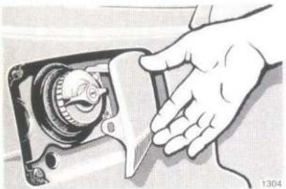
natural_image
Illustration of a hand operating a mechanical device with a dial (no text or symbols visible)
text_image
Diagram of a car electrical switch with labeled components and wiring, showing motor, gear, and battery connections.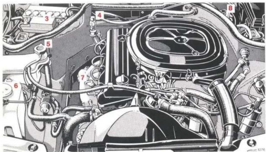
text_image
Technical diagram of an automotive engine with numbered components for identificationThe opposite figure shows the engine compartment of type 230 E
1 Fuel Reserve: Prior to refuelling, turn filler cap to the left and hold in position to allow excess pressure to be released, if required. Then remove filler cap.
2 Tyre Pressure: Check at least every 14 days. For more details, refer to page 85.
3 Battery: Only replenish with distilled water. See page 90.
4 Fluid Level in Automatic Transmission: See page 79.
5 Coolant Level: See page 77.
6 Windscreen Washer System, Headlamp Cleaning System: See page 128.
7 Oil Level in Engine: See page 78.
8 Brake Fluid: See pages 127 and 129.
Vehicle Lighting: Test function and check if clean. For renewal of bulbs, refer to pages 88, 89 and 90.
What You Need to Know at the Petrol Station
- Fuel: For recommended fuels, refer to page 129. Fuel tank capacity approx. 70 l. This includes a 9 l reserve.
Only fill fuel tank until the discharge nozzle unit cuts out – do not overfill.
- Engine Oil: Engine oil level check see page 78. Quantity differential between upper and lower dipstick marking level: 2 l.
Year-round multigrade oils 10 W-40, 10 W-50, 15 W-40, 15 W-50.
For further data see page 125.
● Automatic Transmission: Automatic transmission fluid for automatic transmission.
For level checks and replenishment, refer to page 79.
● Coolant: For normal replenishment, use water (potable water quality).
For further information (e.g. anticorrosion/anti-freeze agent), refer to page 130.
- Bulbs: Main and dipped beam H 4 (60/55 W), fog lamps H 3 (55 W), tail lamps 10 W, turn signal lamps 21 W, stop lamps 21 W, rear fog lamp 21 W, number plate lamps (festoon bulb) 5 W.
- Spark Plugs: Approved spark plugs refer to "Technical Data".
- Tyre Pressure:
(bar gauge pressure)
Cold tyres:
200 260 E
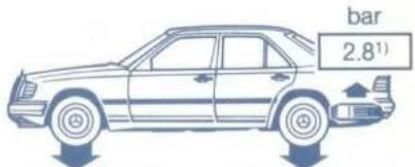
text_image
bar 2.8¹)200 E 230 E
230 CE


300 E


300 CE
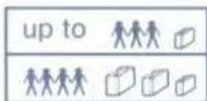


260 E 4MATIC
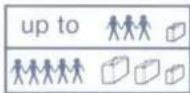


1) 230 E, 230 CE: 2.6 bar
260 E 4MATIC, 300 E 4MATIC: 2.7 bar
2) When driving at speeds up to 180 km/h: -0.2 bar
3) When driving at speeds up to 180 km/h: -0.3 bar
Warm tyres:
Pressure may rise by up to +0.3 bar. Never release any air!
DAIMLER-BENZ AG
Stuttgart-Untertuerkheim