SR7000 - Recepteur MARANTZ - Notice d'utilisation et mode d'emploi gratuit
Retrouvez gratuitement la notice de l'appareil SR7000 MARANTZ au format PDF.


| Type de produit | Récepteur AV Surround |
| Marque | Marantz |
| Modèle | SR7000 |
| Dimensions (L x H x P) | 440 x 159 x 460 mm |
| Poids | 14,5 kg |
| Alimentation | 120 V AC, 60 Hz, 360 W |
| Puissance de sortie (5 canaux) | 100 W par canal (8 ohms, 20 Hz - 20 kHz, 0,05 % THD) |
| Formats audio pris en charge | Dolby Digital, DTS, Dolby Pro Logic, PCM 96 kHz/24 bits |
| Entrées numériques | 3 coaxiales, 2 optiques |
| Sorties numériques | 1 optique, 1 coaxiale |
| Entrées vidéo | 5 composite, 5 S-Vidéo |
| Sorties vidéo | 2 composite, 2 S-Vidéo, 1 moniteur TV |
| Tuner FM/AM | FM 87,5-108 MHz, AM 520-1710 kHz, 50 présélections |
| Télécommande | RC7000SR programmable et auto-apprenante |
| Fonction multiroom | Oui, avec sortie audio et vidéo indépendante |
| Sorties pré-ampli | Avant, central, surround, caisson de basses (5.1) |
| Entrée 6 canaux | Pour décodeur externe |
| Entretien et nettoyage | Débrancher avant nettoyage, utiliser un chiffon doux et sec |
| Sécurité | Ne pas exposer à l'eau ou à l'humidité ; ne pas ouvrir le boîtier ; confier toute réparation à un personnel qualifié |
| Pièces détachées et réparabilité | Contacter un revendeur agréé Marantz ou le service après-vente |
FOIRE AUX QUESTIONS - SR7000 MARANTZ
Questions des utilisateurs sur SR7000 MARANTZ
0 question sur cet appareil. Repondez a celles que vous connaissez ou posez la votre.
Poser une nouvelle question sur cet appareil
Téléchargez la notice de votre Recepteur au format PDF gratuitement ! Retrouvez votre notice SR7000 - MARANTZ et reprennez votre appareil électronique en main. Sur cette page sont publiés tous les documents nécessaires à l'utilisation de votre appareil SR7000 de la marque MARANTZ.
MODE D'EMPLOI SR7000 MARANTZ
maramtiz®
Model SR7000 User Guide
AV Surround Receiver
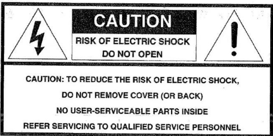
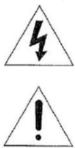
The lightning flash with arrowhead symbol, within an equilateral triangle, is intended to alert the user to the presence of uninsulated "dangerous voltage" within the product's enclosure that may be of sufficient magnitude to constitute a risk of electric shock to persons.
The exclamation point within an equilateral triangle is intended to alert the user to the presence of important operating and maintenance (servicing) instructions in the literature accompanying the appliance.
WARNING
TO REDUCE THE RISK OF FIRE OR ELECTRIC SHOCK, DO NOT EXPOSE THIS APPLIANCE TO RAIN OR MOISTURE.
CAUTION: TO PREVENT ELECTRIC SHOCK, MATCH WIDE BLADE OF PLUG TO WIDE SLOT, FULLY INSERT.
ATTENTION: POUR ÉVITER LES CHOCS ÉLECTRIQUES, INTRODUIRE LA LAME LA PLUS LARGE DE LA FICHE DANS LA BORNE CORRESPONDANTE DE LA PRISE ET POUSSER JUSQU'AU FOND.
NOTE TO CATV SYSTEM INSTALLER:
This reminder is provided to call the CATV (Cable-TV) system installer's attention to Article 820-40 of the NEC, that provides guidelines for proper grounding and, in particular, specified that the cable ground shall be connected to the grounding system of the building, as close to the point of cable entry as practical.
NOTE:
This equipment has been tested and found to comply with the limits for a Class B digital device, pursuant to Part 15 of the FCC Rules. These limits are designed to provide reasonable protection against harmful interference in a residential installation. This equipment generates, uses and can radiate radio frequency energy and, if not installed and used in accordance with the instructions, may cause harmful interference to radio communications. However, there is no guarantee that interference will not occur in a particular installation. If this equipment does cause harmful interference to radio or television reception, which can be determined by tuning the equipment off and on, the user is encouraged to try to correct the interference by one or more of the following measures:
- Reorient or relocate the receiving antenna.
- Increase the separation between the equipment and receiver.
- Connect the equipment into an outlet on a circuit different from that to which the receiver is connected.
- Consult the dealer or an experienced radio/TV technician for help.
NOTE:
Changes or modifications may cause this unit to fail to comply with Part 15 of the FCC Rules and may void the user's authority to operate the equipment.
TABLE OF CONTENTS
INTRODUCTION 3
DESCRIPTION....3
FEATURES
FRONT PANEL FEATURES ....
REAR PANEL CONNECTIONS....5
REMOTE CONTROL UNIT RC7000SR....
OPERATION OF REMOTE CONTROL UNIT .... 9
SET-UP 10
ON SCREEN DISPLAY MENU SYSTEM 10
OSD MAIN MENU 11
SYSTEM SETUP 12
SPEAKERS SETUP 12
SURROUND MODE 13
CHANNEL LEVEL CONTROL....
MULTI ROOM SETUP
BASIC OPERATION .... 14
LISTENING TO THE TUNER .... 14
PLAYBACK OPERATION ....
OTHER FUNCTIONS....15
SETTING THE SLEEP TIMER (ONLY REMOTE CONTROL UNIT)
TV AUTO ON/OFF FUNCTION ....
MULTI ROOM SELECTOR
ON SCREEN DISPLAY INFOMATION
REMOTE CONTROL UNIT RC7000....
MAIN FEATURES & FUNCTIONS....18
NAMES OF PARTS & FUNCTIONS....16
BASIC OPERATION .... 20
OTHER FUNCTIONS .... 20
BATTERY LIFE ....26
NUMBER OF LEARNABLE CODES ....
JOG DIAL COMMAND FUNCTIONS LISTING ....
SURROUND MODES 20
TROUBLESHOOTING .... 30
TECHNICAL SPECIFICATIONS .... 32
AUDIO SYSTEM CONNECTIONS FOR AUDIO COMPONENTS
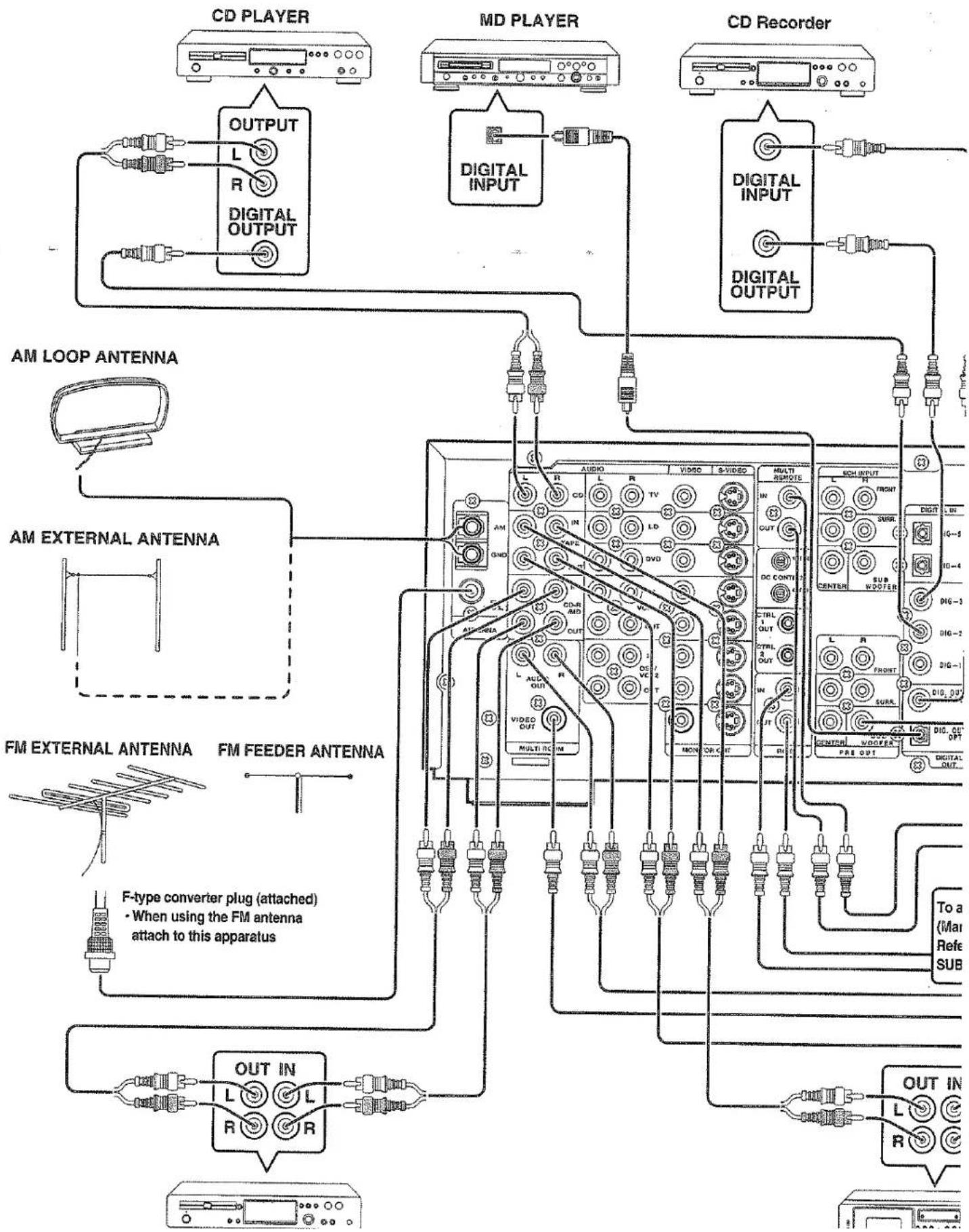
flowchart
graph TD
    subgraph Left_Side
        A["CD PLAYER"] --> B["OUTPUT"]
        B --> C["L"]
        B --> D["R"]
        B --> E["DIGITAL OUTPUT"]
        F["MD PLAYER"] --> G["OUTPUT"]
        G --> H["DIGITAL INPUT"]
        I["CD Recorder"] --> J["DIGITAL INPUT"]
        J --> K["DIGITAL OUTPUT"]
    end

    subgraph Right_Side
        L["AM LOOP ANTENNA"] --> M["AM EXTERNAL ANTENNA"]
        N["FM EXTERNAL ANTENNA"] --> O["FM FEEDER ANTENNA"]
        P["F-type converter plug (attached) - When using the FM antenna attach to this apparatus"]
    end

    subgraph Bottom_Side
        Q["OUT IN"] --> R["L"]
        Q --> S["L"]
        Q --> T["R"]
        U["To a (Max Refe SUB)"] --> V["L"]
        W["To a (Max Refe SUB)"] --> X["R"]
    end

    A --> G
    F --> J
    N --> O
    Q --> R
    U --> T
    V --> X
    W --> Y
    X --> Z
    Y --> AA
    AA --> AB
    AC["AM LOOP ANTENNA"] --> M
    AD["FM EXTERNAL ANTENNA"] --> O
    AE["FM FEEDER ANTENNA"] --> O
    AF["CD Recorder"] --> J
    AG["CD Player"] --> G
    AH["CD Player"] --> G
    AI["CD Player"] --> G
    AJ["CD Player"] --> G
    AK["CD Player"] --> G
    AL["CD Player"] --> G
    AM["CD Player"] --> G
    AN["CD Player"] --> G
    AO["CD Player"] --> G
    AP["CD Player"] --> G
    AQ["CD Player"] --> G
    AR["CD Player"] --> G
    AS["CD Player"] --> G
    AT["CD Player"] --> G
    AU["CD Player"] --> G
    AV["CD Player"] --> G
    AW["CD Player"] --> G
    AX["CD Player"] --> G
    AY["CD Player"] --> G
    AZ["CD Player"] --> G
    BA["CD Player"] --> G
    BB["CD Player"] --> G
    BC["CD Player"] --> G
    BD["CD Player"] --> G
    BE["CD Player"] --> G
    BF["CD Player"] --> G
    BG["CD Player"] --> G
    BH["CD Player"] --> G
    BI["CD Player"] --> G
    BJ["CD Player"] --> G
    BK["CD Player"] --> G
    BL["CD Player"] --> G
    BM["CD Player"] --> G
    BN["CD Player"] --> G
    BO["CD Player"] --> G
    BP["CD Player"] --> G
    BQ["CD Player"] --> G
    BR["CD Player"] --> G
    BS["CD Player"] --> G
    BT["CD Player"] --> G
    BU["CD Player"] --> G
    BV["CD Player"] --> G
    BW["CD Player"] --> G
    BX["CD Player"] --> G
    BY["CD Player"] --> G
    BZ["CD Player"] --> G
    CA["CD Player"] --> G
    CB["CD Player"] --> G
    CC["CD Player"] --> G
    DD["CD Player"] --> G
    DJ["CD Player"] --> G
    DK["CD Player"] --> G
    DL["CD Player"] --> G
    DV["CD Player"] --> G
    DW["CD Player"] --> G
    DX["CD Player"] --> G
    DXB["DC CONTIN OUT"] --> G
    DXC["DC CONTIN OUT"] --> G
    DXF["DC CONTIN OUT"] --> G
    DXG["DC CONTIN OUT"] --> G
    DXH["DC CONTIN OUT"] --> G
    DXI["DC CONTIN OUT"] --> G
    DXJ["DC CONTIN OUT"] --> G
    DXK["DC CONTIN OUT"] --> G
    DXL["DC CONTIN OUT"] --> G
    DXM["DC CONTIN OUT"] --> G
    DXN["DC CONTIN OUT"] --> G
    DXO["DC CONTIN OUT"] --> G
    DXP["DC CONTIN OUT"] --> G
    DXQ["DC CONTIN OUT"] --> G
    DXR["DC CONTIN OUT"] --> G
    DXS["DC CONTIN OUT"] --> G
    DXT["DC CONTIN OUT"] --> G
    DXU["DC CONTIN OUT"] --> G
    DXV["DC CONTIN OUT"] --> G
    DXW["DC CONTIN OUT"] --> G
    DXX["DC CONTIN OUT"] --> G
    DXY["DC CONTIN OUT"] --> G
    DXZ["DC CONTIN OUT"] --> G

    subgraph Top_Side
        B1["AUDIO"]
        B2["VUDIO"]
        B3["S+VIDEO"]
        B4["MULTI REMOTE"]
        B5["L"]
        B6["C"]
        B7["L"]
        B8["TV"]
        B9["L"]
        B10["L"]
        B11["L"]
        B12["L"]
        B13["L"]
        B14["L"]
        B15["L"]
        B16["L"]
        B17["L"]
        B18["L"]
        B19["L"]
        B20["L"]
        B21["L"]
        B22["L"]
        B23["L"]
        B24["L"]
        B25["L"]
        B26["L"]
        B27["L"]
        B28["L"]
        B29["L"]
        B30["L"]
        B31["L"]
        B32["L"]
        B33["L"]
        B34["L"]
        B35["L"]
        B36["L"]
        B37["L"]
        B38["L"]
        B39["L"]
        B40["L"]
        B41["L"]
        B42["L"]
        B43["L"]
        B44["L"]
        B45["L"]
        B46["L"]
        B47["L"]
        B48["L"]
        B49["L"]
        B50["L"]
        B51["L"]
        B52["L"]
        B53["L"]
        B54["L"]
        B55["L"]
        B56["L"]
        B57["L"]
        B58["L"]
        B59["L"]
        B60["L"]
        B61["L"]
        B62["L"]
        B63["L"]
        B64["L"]
        B65["L"]
        B66["L"]
        B67["L"]
        B68["L"]
        B69["L"]
        B70["L"]
        B71["L"]
        B72["L"]
        B73["L"]
        B74["L"]
        B75["L"]
        B76["L"]
        B77["L"]
        B78["L"]
        B79["L"]
        B80["L"]
        B81["L"]
        B82["L"]
        B83["L"]
        B84["L"]
        B85["L"]
        B86["L"]
        B87["L"]
        B88["L"]
        B89["L"]
        B90["L"]

    subgraph Top_Internal ANTenna
      A1["FM EXTERNAL ANTENNA"] -.-> A2["FM FEEDER ANTENNA"]
flowchart
graph TD
    A["NORMAL INPUT INVERT OUTPUT"] --> B["SUBWOOFER AMPLIFIER (MA500 or MA700)"]
    B --> C["SURROUND SPEAKER"]
    C --> D["AC OUTLETS 120W 1A"]
    D --> E["MULTI ROOM INPUT"]
    E --> F["IR RECEIVER"]
    F --> G["MULTI ROOM SPEAKER"]
    G --> H["MAIN AMP (For MULTI ROOM)"]
    H --> I["MONITOR TV for MULTI ROOM"]
    I --> J["VIDEO IN"]
    J --> K["LINE IN L R"]
    K --> L["AC OUTLETS 120W 1A"]
    style A fill:#f9f,stroke:#333
    style B fill:#ccf,stroke:#333
    style C fill:#cfc,stroke:#333
    style D fill:#fcc,stroke:#333
    style E fill:#cff,stroke:#333
    style F fill:#ffc,stroke:#333
    style G fill:#cfc,stroke:#333
    style H fill:#fcc,stroke:#333
    style I fill:#ffc,stroke:#333
    style J fill:#fcc,stroke:#333
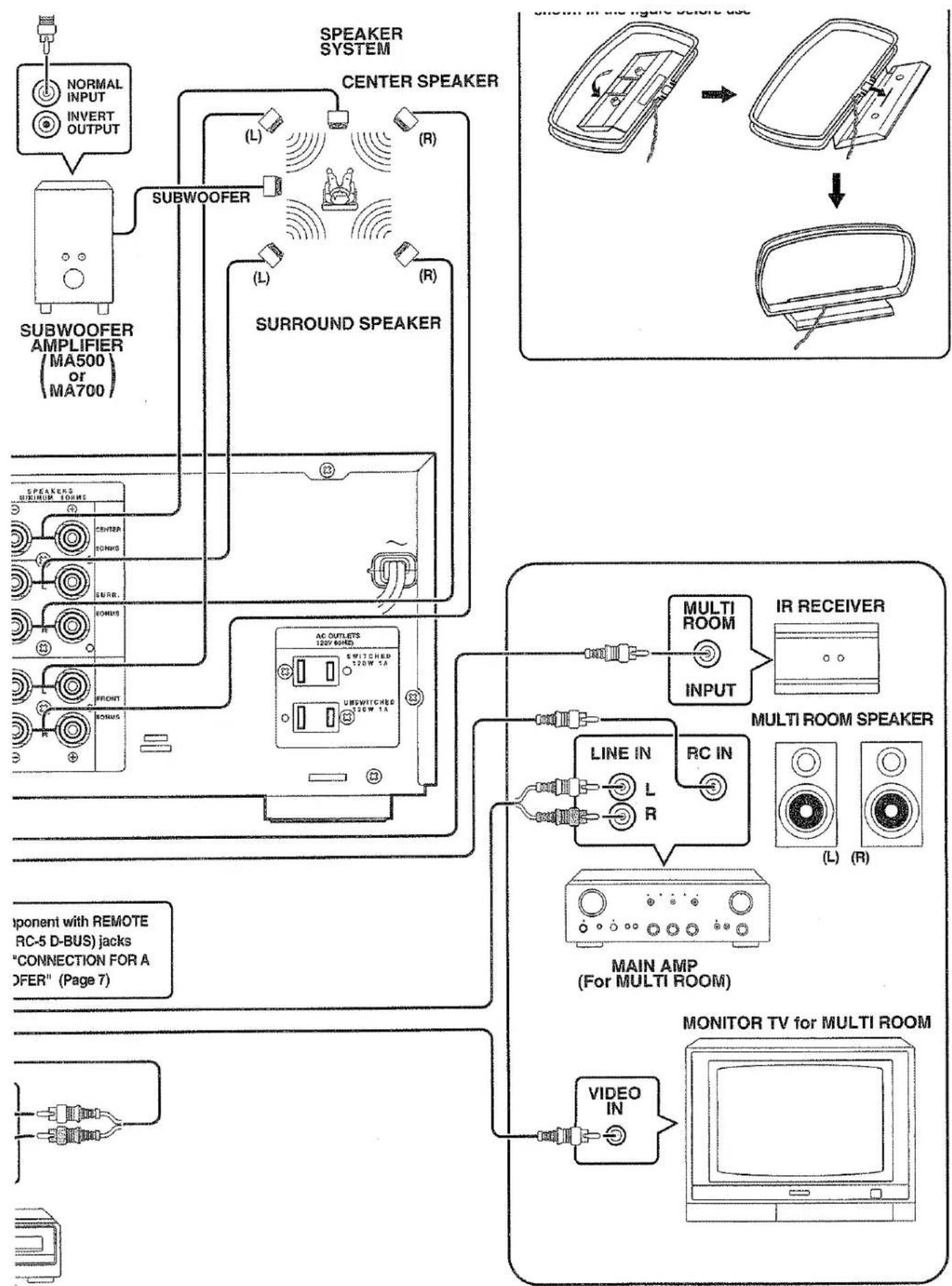
MULTI ROOM
As opening or removing covers may expose you to dangerous voltage or other hazards. Refer all servicing to qualified service personnel.
- Damage Requiring Service-Unplug this video product from the wall outlet and refer servicing to qualified service personnel under the following conditions:
a. When the power-supply cord or plug is damaged.
b. If liquid has been spilled, or objects have fallen into the video product.
c. If the video product has been exposed to rain or water.
d. If the video product does not operate normally by following the operating instructions. Adjust only those controls that are covered by the operating instructions as an improper adjustment of other controls may result in damage and will often require extensive work by a qualified technician to restore the video product to its normal operation.
e. If the video product has been dropped or the cabinet has been damaged.
f. When the video product exhibits a distinct change in performance-this indicates a need for service.
sure the service technician has used replacement parts specified by the manufacturer or have the same characteristics as the original part. Unauthorized substitutions may result in fire, electric shock or other hazards.
-
Safety Check-Upon completion of any service or repairs to this video product, ask the service technician to perform safety checks to determine that the video product is in proper operating condition.
-
Carts and Stands-The appliance should be used only with a cart or stand that is recommended by the manufacturer.
-
An appliance and cart combination should be moved with care. Quick stops, excessive force, and uneven surfaces may cause the appliance and cart combination to overturn.

FIGURE 1
EXAMPLE OF ANTENNA GROUNDING ACCORDING TO NATIONAL ELECTRICAL CODE INSTRUCTIONS
INED IN ARTICLE 810 - "RADIO AND TELEVISION EQUIP
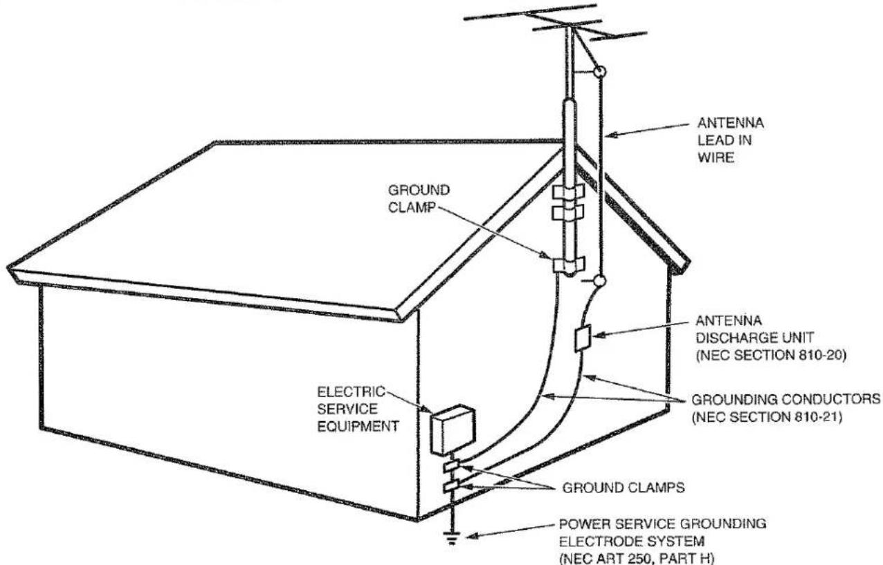
NEC - NATIONAL ELECTRICAL CODE
VIDEO SYSTEM CONNECTIONS FOR VIDEO COMPONENTS
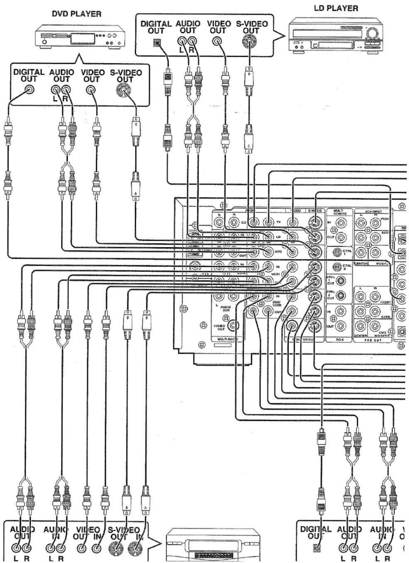
flowchart
graph TD
    subgraph_DVD_PLAYER["DVD PLAYER"]
        A1["DIGITAL OUT"] --> B1["AUDIO OUT"]
        A2["DIGITAL OUT"] --> B2["VIDEO OUT"]
        A3["DIGITAL OUT"] --> B3["S-VIDEO OUT"]
    end

    subgraph_LD_PLAYER["LD PLAYER"]
        C1["LD INPUT"] --> D1["Multi REMOTE"]
        C2["Multi REMOTE"] --> D2["SCN INPUT"]
        C3["SCN INPUT"] --> D3["OUT"]
        C4["OUT"] --> D4["CTRL"]
        C5["CTRL"] --> D5["CONTROL"]
        C6["CONTROL"] --> D6["CONTROL"]
        C7["CONTROL"] --> D7["CONTROL"]
        C8["CONTROL"] --> D8["CONTROL"]
        C9["CONTROL"] --> D9["CONTROL"]
        C10["CONTROL"] --> D10["CONTROL"]
        C11["CONTROL"] --> D11["CONTROL"]
        C12["CONTROL"] --> D12["CONTROL"]
        C13["CONTROL"] --> D13["CONTROL"]
        C14["CONTROL"] --> D14["CONTROL"]
        C15["CONTROL"] --> D15["CONTROL"]
        C16["CONTROL"] --> D16["CONTROL"]
        C17["CONTROL"] --> D17["CONTROL"]
        C18["CONTROL"] --> D18["CONTROL"]
        C19["CONTROL"] --> D19["CONTROL"]
        C20["CONTROL"] --> D20["CONTROL"]
        C21["CONTROL"] --> D21["CONTROL"]
        C22["CONTROL"] --> D22["CONTROL"]
        C23["CONTROL"] --> D23["CONTROL"]
        C24["CONTROL"] --> D24["CONTROL"]
        C25["CONTROL"] --> D25["CONTROL"]
        C26["CONTROL"] --> D26["CONTROL"]
        C27["CONTROL"] --> D27["CONTROL"]
        C28["CONTROL"] --> D28["CONTROL"]
        C29["CONTROL"] --> D29["CONTROL"]
        C30["CONTROL"] --> D30["CONTROL"]
        C31["CONTROL"] --> D31["CONTROL"]
        C32["CONTROL"] --> D32["CONTROL"]
        C33["CONTROL"] --> D33["CONTROL"]
        C34["CONTROL"] --> D34["CONTROL"]
        C35["CONTROL"] --> D35["CONTROL"]
        C36["CONTROL"] --> D36["CONTROL"]
        C37["CONTROL"] --> D37["CONTROL"]
        C38["CONTROL"] --> D38["CONTROL"]
        C39["CONTROL"] --> D39["CONTROL"]
        C40["CONTROL"] --> D40["CONTROL"]
        C41["CONTROL"] --> D41["CONTROL"]
        C42["CONTROL"] --> D42["CONTROL"]
        C43["CONTROL"] --> D43["CONTROL"]
        C44["CONTROL"] --> D44["CONTROL"]
        C45["CONTROL"] --> D45["CONTROL"]
        C46["CONTROL"] --> D46["CONTROL"]
        C47["CONTROL"] --> D47["CONTROL"]
        C48["CONTROL"] --> D48["CONTROL"]
        C49["CONTROL"] --> D49["CONTROL"]
        C50["Control"] --> D50
    end

    subgraph DVD tighter
        A1 & A2 & A3 & A4 & A5 & A6 & A7 & A8 & A9 & A10 & A11 & A12 & A13 & A14 & A15 & A16 & A17 & A18 & A19 & A20 & A21 & A22 & A23 & A24 & A25 & A26 & A27 & A28 & A29 & A30 & A31 & A32 & A33 & A34 & A35 & A36 & A37 & A38 & A39 & A40 & A41 & A42 & A43 & A44 & A45 & A46 & A47 & A48 & A49 & A50 & A51 & A52 & A53 & A54 & A55 & A56 & A57 & A58 & A59 & A60 & A61 & A62 & A63 & A64 & A65 & A66 & A67 & A68 & A69 & A70 & A71 & A72 & A73 & A74 & A75 & A76 & A77 & A78 & A79 & A80
    end

    B1 --> B2
    B2 --> B3
    B3 --> B4
    B4 --> B5
    B5 --> B6
    B6 --> B7
    B7 --> B8
    B8 --> B9
    B9 --> B10
    B10 --> B11
    B11 --> B12
    B12 --> B13
    B13 --> B14
    B14 --> B15
    B15 --> B16
    B16 --> B17
    B17 --> B18
    B18 --> B19
    B19 --> B20
    B20 --> B21
    B21 --> B22
    B22 --> B23
    B23 --> B24
    B24 --> B25
    B25 --> B26
    B26 --> B27
    B27 --> B28
    B28 --> B29
    B29 --> B30
    B30 --> B31
    B31 --> B32
    B32 --> B33
    B33 --> B34
    B34 --> B35
    B35 --> B36
    B36 --> B37
    B37 --> B38
    B38 --> B39
    B39 --> B40
    B40 --> B41
    B41 --> B42
    B42 --> B43
    B43 --> B44
    B44 --> B45
    B45 --> B46
    B46 --> B47
    B47 --> B48
    B48 --> B49
    B49 --> B50
    B50 --> B51
    B51 --> B52
    B52 --> B53
    B53 --> B54
    B54 --> B55
    B55 --> B56
    B56 --> B57
    B57 --> B58
    B58 --> B59
    B59 --> B60
    B60 --> B61
    B61 --> B62
    B62 --> B63
    B63 --> B64
    B64 --> B65
    B65 --> B66
    B66 --> B67
    B67 --> B68
    B68 --> B69
    B69 --> B70
    B70 --> B71
    B71 --> B72
    B72 --> B73
    B73 --> B74
    B74 --> B75
    B75 --> B76
    B76 --> B77
    B77 --> B78
    B78 --> B79
    B79 --> B80
    B80 --> B81
    B81 --> B82
    B82 --> B83
    B83 --> B84
    B84 --> B85
    B85 --> B86
    B86 --> B87
    B87 --> B88
    B88 --> B89
    B89 --> B90
    style DVD tighter fill:#f9f,stroke:#333,stroke-width:2px
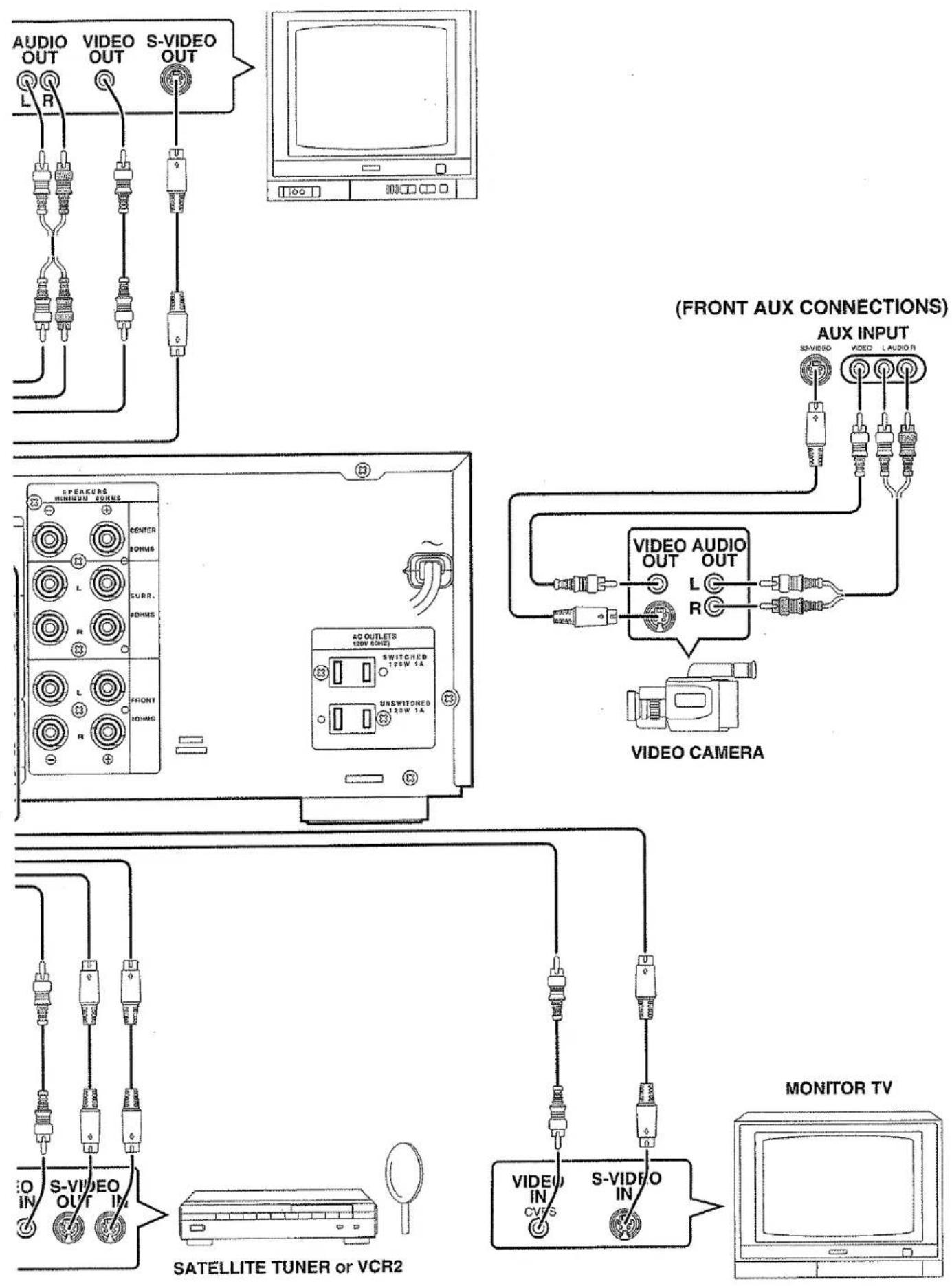
IMPORTANT SAFETY INSTRUCTIONS
READ BEFORE OPERATING EQUIPMENT
This product was designed and manufactured to meet strict quality and safety standards. There are, however, some installation and operation precautions which you should be particularly aware of.
- Read Instructions - All the safety and operating instructions should be read before the appliance is operated.
- Retain Instructions-The safety and operating instructions should be retained for future reference.
- Heed Warnings-All warnings on the appliance and in the operating instructions should be adhered to.
- Follow Instructions-All operating and use instructions should be followed.
- Cleaning-Unplug this video product from the wall outlet before cleaning. Do not use liquid cleaners or aerosol cleaners. Use a damp cloth for cleaning.
-
Attachments-Do not use attachments not recommended by the video product manufacturer as they may cause hazards.
-
Water and Moisture-Do not use this video product near water-for example, near a bath tub, wash bowl, kitchen sink, or laundry tub, in a wet basement, or near a swimming pool, and the like.
-
Accessories-Do not place this video product on an unstable cart, stand, tripod, bracket, or table. The video product may fall, causing serious injury to a child or adult, and serious damage to the appliance. Use only with a cart, stand, tripod, bracket, or table recommended by the manufacturer, or sold with the video product. Any mounting of the appliance should follow the manufacturer's instructions, and should use a mounting accessory recommended by the manufacturer.
-
Ventilation-Slots and openings in the cabinet are provided for ventilation and to ensure reliable operation of the video product and to protect it from overheating, and these openings must not be blocked or covered. The openings should never be blocked by placing the video product on a bed, sofa, rug, or other similar surface. This video product should never be placed near or over a radiator or heat register. This video product should not be placed in a built-in installation such as a bookcase or rack unless proper ventilation is provided or the manufacturer's instructions have been adhered to.
-
Power Sources-This video product should be operated only from the type of power source indicated on the marking label. If you are not sure of the type of power supply to your home, consult your appliance dealer or local power company. For video products intended to operate from battery power, or other sources, refer to the operating instructions.
-
Grounding or Polarization-This video product is equipped with a polarized alternating-current line plug (a plug having one blade wider than the other). This plug will fit into the power outlet only one way. This is a safety feature. If you are unable to insert the plug fully into the outlet, try reversing the plug. If the plug should still fail to fit, contact your electrician to replace your obsolete outlet. Do not defeat the safety purpose of the polarized plug.
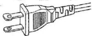
AC POLARIZED PLUG
- Power-Cord Protection-Power-supply cords should be routed so that they are not likely to be walked on or pinched by items placed upon or against them, paying particular attention to cords at plugs, convenience receptacles, and the point where they exit from the appliance.
- Protective Attachment Plug - The appliance is equipped with an attachment plug having overload protection. This is a safety feature. See Instruction Manual for replacement or resetting of protective device. If replacement of the plug is required, be sure the service technician has used a replacement plug specified by the manufacturer that has the same overload protection as the original plug.
- Outdoor Antenna Grounding-If an outside antenna or cable system is connected to the video product, be sure the antenna or cable system is grounded so as to provide some protection against voltage surges and built up static charges. Section 810 of the National Electrical Code, ANSI/NFPA No. 70-1984, provides information with respect to proper grounding of the mast and supporting structure, grounding of the lead-in wire to an antenna discharge unit, size of grounding conductors, location of antenna-discharge unit, connection to grounding electrodes, and requirements for the grounding electrode. See Figure 1.
- Lightning-For added protection for this video product receiver during a lightning storm, or when it is left un-attended and unused for long periods of time, unplug it from the wall outlet and disconnect the antenna or cable system. This will prevent damage to the video product due to lightning and power-line surges.
- Power Lines-An outside antenna system should not be located in the vicinity of overhead power lines or other electric light or power circuits, or where it can fall into such power lines or circuits. When installing an outside antenna system, extreme care should be taken to keep from touching such power lines or circuits as contact with them might be fatal.
- Overloading-Do not overload wall outlets and extension cords as this can result in a risk of fire or electric shock.
- Object and Liquid Entry-Never push objects of any kind into this video product through openings as they may touch dangerous voltage points or short-out parts that could result in a fire or electric shock. Never spill liquid of any kind on the video product.
INTRODUCTION
Thank you for purchasing the Marantz SR7000 DTS/Dolby Digital Surround receiver.
This remarkable component has been engineered to provide you with many years of home theater enjoyment.
Please take a few minutes to read this manual thoroughly before you connect and operate the SR7000.
As there are a number of connection and configurations options, you are encouraged to discuss your own particular home theater setup with your Marantz A/V specialist dealer.
DESCRIPTION
DIGITAL
SURROUND
DTS was introduced in 1994 to provide 5.1 channels of discrete digital audio into home theater systems.
DTS brings you premium quality, discrete multi-channel digital sound to both movies and music.
DTS is a multi-channel sound system designed to create full range digital sound reproduction.
The no compromise DTS digital process sets the standard of quality for cinema sound by delivering an exact copy of the studio master recordings to neighborhood and home theaters.
Now, every moviegoer can hear the sound exactly as the moviemaker intended.
DTS can be enjoyed in the home for either movies or music on DVD's, LD's, and CD's.
DIGITAL
Dolby Digital lets you enjoy Digital TV, Digital Satellite as well as DVD and LD software in digital surround, which is the next step above Dolby Pro Logic.
In comparison with Dolby Pro Logic, Dolby Digital can provide separate left and right surround channels, for more precise localization of sounds and a more convincing, realistic ambience. And, with Dolby Digital, all five main channels can be full range and a subwoofer can be added to each channel, if desired. By providing up to 5.1 channels of digital audio independently, Dolby Digital lets you enjoy better sound quality and more powerful presence than conventional Dolby Surround.
"Dolby", "AC-3", "Pro Logic" and the double-D symbol are trademarks of Dolby Laboratories.
"DTS" and "DTS Digital Surround" are trademarks of Digital Theater Systems, Inc.
FEATURES
- Dolby Digital and DTS surround sound decoding, plus Dolby Pro Logic decoding and a variety of additional surround modes.
- 96 kHz/ 24 bit decoding for highest possible fidelity and bandwidth, and high-resolution playback of 96 kHz/ 24 bit PCM audio sources.
- 100 watts to each of the five main channels; the power amp section features advanced, premium high-storage power supply capacitors, and fully discrete output stages housed in cast aluminum heat sinks.
- 5.1 channel pre-amp outputs for connection to external components such as a subwoofer and external power amplifiers.
- Six-channel direct inputs accommodate future surround sound formats or an external digital decoder.
- 5 Digital inputs, for connection to other sources, such as DVD, DSS, CD or LD.
• 2 Digital outputs for connection to CD-R or MD.
• High-quality AM/FM tuner with 50 station presets. - Source Direct switch bypasses, tone controls and bass management for purest audio quality.
• S-video and composite video switching - On-Screen-Display with both Composite and "S" video.
- Front panel A/V inputs, with S-video.
- Easy to use, on-screen menu.
- Multi-room capability offers independent control of a second room audio and video system.
• Supplied with RC7000SR Programmable Learning Remote Control.
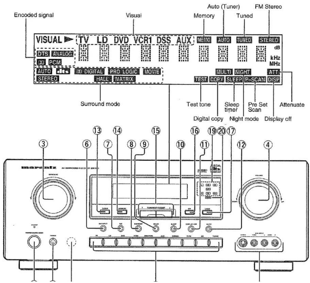
FRONT PANEL FEATURES (SEE PAGE 1.)
① POWER switch and STANDBY indicator
When this switch is pressed once, the unit turns ON and display appears on the display panel. When pressed again, the unit turns OFF and the STANDBY indicator lights.
When the STANDBY indicator lights, the unit is NOT disconnected from the AC power.
② PHONES jack for stereo headphones
Conventional dynamic headphones can be plugged in here.
Notes:
When using headphones, the surround mode is switched automatically to STEREO and the sound from the speakers is muted. The surround mode returns to the previous setting as soon as the plug is removed from the jack.
③ SURROUND MODE Selector knob
When this knob is turned, the surround mode is switched in the following sequence.

flowchart
graph TD
    A["AUTO"] --> B["DTS-cinema"]
    B --> C["DTS-music"]
    C --> D["DOLBY"]
    E["STEREO"] --> F["5 STEREO"]
    F --> G["MATRIX"]
    G --> H["HALL"]
    H --> I["MOVE"]
    style A fill:#f9f,stroke:#333
    style B fill:#f9f,stroke:#333
    style C fill:#f9f,stroke:#333
    style D fill:#f9f,stroke:#333
    style E fill:#f9f,stroke:#333
    style F fill:#f9f,stroke:#333
    style G fill:#f9f,stroke:#333
    style H fill:#f9f,stroke:#333
    style I fill:#f9f,stroke:#333
Not all modes will be present if an analog input is selected.
④ VOLUME control knob
Adjusts the overall sound level. Turning the control clockwise increases the sound level.
⑤ FUNCTION SELECTOR buttons (AUDIO/VIDEO)
These buttons are used to select the sources.
The video function selector, such as TV, LD, DVD, VCR1, DSS/VCR2, and AUX, selects video and audio simultaneously.
Audio function sources such as CD, TAPE, CDR/MD, and TUNER may be selected in conjunction with a Video source.
This feature (Sound injection) combines a sound from one source with a picture from another.
Choose the video source first, and then choose a different audio source to activate this function.
⑥ 6CH INPUT button
Press this button to select the output of an external multi channel decoder.
⑦ A/D (Analog/Digital) SELECTOR button
This is used to select between the analog and digital inputs.
Note:
This button is not used for an input source that is not connected to a digital input.
⑧ S. (Source) DIRECT button
When this button is pressed, the tone control circuitry is bypassed as well as Bass Management.
Notes:
The surround mode is automatically switched to AUTO when the source direct function is turned on.
Additionally, Speaker Configurations are fixed automatically as follow.
Front SPKR = Large
Center SPKR = Large
Surround SPKR = Large
Sub woofer = On
⑨ MULTI (Multi Room) button
Press this button to switch the unit to multi room mode. "MULTI ROOM" appears in the display.
⑩ SLEEP button
Set the sleep timer function with this button.
⑪ DISPLAY OFF button
When this button is pressed, the display is turned off and the display off indicator lights up (DISP).
Press this button again to turn the display ON again.
⑫ MUTE button
Press this button to mute the output to the speakers. Press it again to return to the previous volume level.
⑬ CLEAR button
Press this button to cancel the station memory setting mode or preset scan tuning.
⑭ MEMORY button
Press this button to enter the tuner preset memory numbers and station names.
⑮ TUNING / PRESET UP and DOWN buttons
During reception of AM or FM, you can scan the other frequencies or select another preset station pressing these buttons.
⑯ FREQUENCY / PRESET buttons
During reception of AM or FM, you can change the function of the UP/DOWN buttons for scanning frequencies or selecting preset stations by pressing these buttons.
⑰ FM MODE button
Press this button to select the auto stereo mode or mono mode when the FM band is selected. The AUTO indicator lights in the auto stereo mode.
⑱ INFRARED SENSOR window
This window receives infrared signals from the remote control unit.
⑲ ENCODED CHANNEL STATUS indicators
These indicators display the channels that are encoded with a digital input signal.
If the selected digital input signal is Dolby Digital 5.1ch or DTS 5.1ch, "L", "C", "R", "LS", "RS" and "LFE" will light up.
If the digital input signal is 2 channel PCM-audio, "L" and "R" will be displayed.
Note:
These indicators are only active with a digital input.
⑳ PEAK indicator
This indicator is a monitor for an analog audio input signal.
if the selected analog audio input signal is greater than the capable level of internal processing, will light.
If this happens, you should press the ATT button.
②1 AUX input jacks
These auxiliary video/audio input jacks accept the connection of a camcorder, portable VCR, etc.
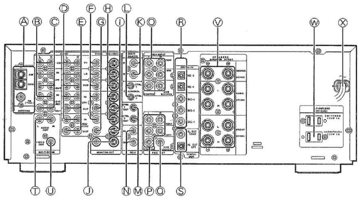
REAR PANEL CONNECTIONS (SEE PAGE 1.)
All connections to the rear panel should be made with the entire system powered off.
To avoid errors, it is advisable to connect one cable at a time between the various components.
Ⓐ FM antenna terminal (75 ohms)
Connect an external FM antenna with a coaxial cable, or a cable network FM source.
AM antenna and ground terminals
Connect the supplied AM loop antenna. Use the terminals marked "AM" and "GND".
The supplied AM loop antenna will provide good AM reception in most areas.
Position the loop antenna until you hear the best reception.
⑧ Three analog audio inputs
CD, TAPE, and CD-R/MD
Connect the audio outputs of your source components to the input jacks on the receiver.
© Two analog audio outputs for audio source equipment
TAPE and CD-R/MD
Connect each output to the audio inputs (REC in) of your recording equipment.
① Five analog audio inputs for video source equipment
TV, LD, DVD, VCR1, and DSS/VCR2
Connect each input to the audio outputs of your video source equipment.
Two analog audio outputs for video source equipment
VCR1, and DSS/VCR2
Connect each output to the audio inputs (REC in) of your video recording equipment.
Five video inputs
Ex: TV.LD.DVD, VCR1, and DSS/VCR2
Connect each input to the video outputs of your video source equipment.
© Two video outputs
VCR1, and DSS/VCR2
Connect each output to the video input (REC in) of your video recording equipment.
H Five S-video inputs
Ex: TV, LD, DVD, VCR1, and DSS/VCR2
Connect each input to the S-video outputs of your video source equipment.
① Two S-video outputs
VCR1, and DSS/VCR2
Connect each output terminals to S-video input (REC in) of your video recording equipment.
TV MUNI. (VIDEO/S-VIDEO) output jacks
Connect the TV MONI jack to your TV's video input (VIDEO IN) jack. You can connect your video equipment with S-VIDEO jacks if possible, or the composite VIDEO jacks.
You must use the same type of connection from your video player into the receiver, and out of the receiver into your TV.
Both must be composite video or both must be S-Video. You cannot convert a signal from one type to the other.
K MULTI ROOM REMOTE I/O terminals
IN: Connect to multi-room remote control device, available from your Marantz dealer.
OUT: Connect to the Marantz component equipped with remote control (RC-5) terminals in another room (Second zone).
DC LEVEL control 1 & 2
This determines the output voltage (5-13 VDC) of the DC trigger jacks.
⑧ DC control output 1 & 2
Connect a device that needs to be triggered by DC under certain conditions (screen, power strip, etc...) Use the system setup menu (3/3) to determine the conditions by which these jacks will be active.
Note:
This output voltage is for (status) control only. It is not sufficient for drive capability.
⑨ REMOTE CONT. IN/OUT terminals
Connect to a Marantz component equipped with remote control (RC-5) terminals.
◎ 6 CH INPUT jacks
Connect to the outputs of an external multichannel decoder.
© PRE OUT jacks
Jacks for Front - L/R, Center and Surround.
Use these jacks for connection to an external power amplifier.
SUB WOOFER output jack
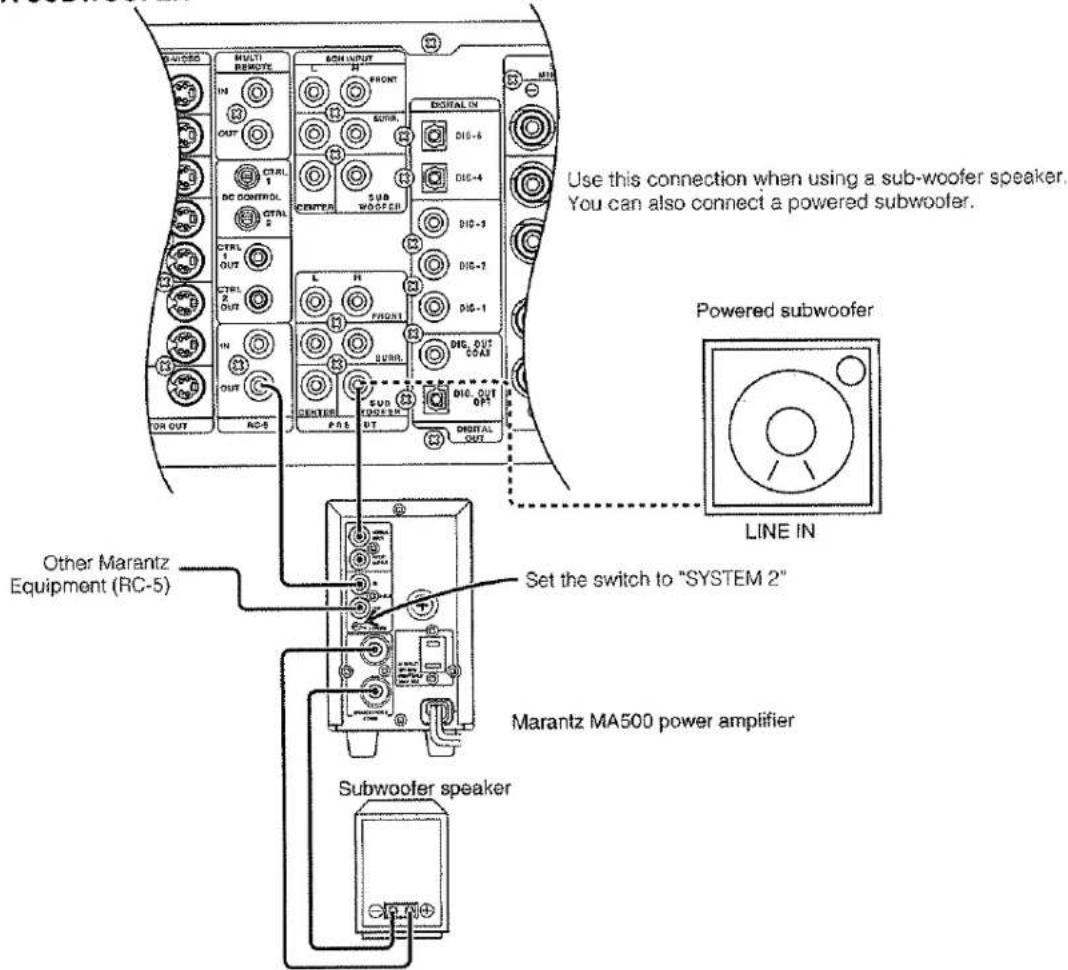
Connect to the input jack(s) of the power amplifier for subwoofer channel or powered subwoofer.
® Five DIGITAL inputs
Dig.1,2,3 (coaxial) and Dig.4,5 (Optical)
Connect each input to the digital output of your source equipment. Use the system setup menu to assign digital input to appropriate source. (see page. 11)
Note :
The coaxial connections are not for AC-3 RF from an LD, If you want to decode this type of signal, an external demodulator must be used.
⑤ Two DIGITAL outputs
Optical and Coaxial
Connect digital input of your digital recording equipment.
① MULTI OUT jacks (Audio)
Connect to the input jacks of the amplifier used to drive the speakers in another room (Second zone).
① MULTI OUT jack (Video)
Connect to the input jack of the TV monitor in another room (Second zone).

SPEAKER terminals
FRONT Left & Right speakers output terminals
Connect to the front left & right speakers.
CENTER speaker output terminals
Connect to the center speaker.
SURROUND Left & Right speakers output terminals
Connect to the surround (rear) left & right speakers.

AC OUTLETS
Connect the power cables of components such as a DVD and CD player to these outlets. Both SWITCHED and UNSWITCHED outlets are provided.
The one marked SWITCHED provides power only when the SR7000 is turned on and is useful for components which you use every time you play your system.
The one marked UNSWITCHED is always live as long as the SR7000 is plugged into a live outlet.
A component connected here may be left on permanently, or may be switched off with its own power switch.
Caution:
In order to avoid potential turn-off thumps, anything plugged in here should be powered up BEFORE the SR7000 is turned on.

POWER cable
Plug into a household AC power outlet.
REMOTE CONTROL DOS CONNECTIONS
This unit is equipped with a remote control function.
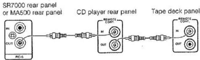
By connecting this unit's remote control jacks to a Marantz CD player or tape deck equipped with remote control (RC-5) jacks, it allows system remote control to operate.
Connect RC-5 OUT jack of SR7000 to REMOTE CONT. IN of other Marantz equipment, i.e. CD player or Cassette deck, by using an RCA pin cable.
Note:
If a component equipped with remote control (RC-5) jacks has an INT/EXT switch on the rear panel, set the switch to EXT when using the system control function.
(Connection example)
flowchart
graph LR
    A["SR7000 rear panel or MA500 rear panel"] --> B["CD player rear panel"]
    B --> C["Tape deck panel"]
    subgraph A
        D["IN"]
        E["OUT"]
        F["RC-5"]
    end
    subgraph B
        G["REMOITE CONT."]
        H["IN"]
        I["OUT"]
    end
    subgraph C
        J["REMOITE CONT."]
        K["IN"]
        L["OUT"]
    end
controlling the power effort of a power amplifier connected to the SR7000 through Marantz remote control
- If you connect the MA500 power amplifier to the SR7000, set the Bus System Selector switch of the MA500 to "System 2". Now the MA500 can be turned ON/OFF in synchronism with the power ON/OFF of the SR7000.
Notes:
- Be sure to connect the remote control bus before the procedure above.
CONNECTION FOR A SUBWOOFER
REMOTE CONTROL UNIT RC7000SR
This chapter describes the functions which need to control the SR7000. See page 18 and following pages to refer other function of the RC7000SR.
4 POWER ON and OFF buttons
These two buttons are use for turning on or off SR7000.
6 Jog Dial
Rotate this dial to select commands displayed on the LCD for each function.
Refer to follow.
7 ENT buttons
Press this button to enter the selected command by the Jog Dial.
| Function | Jog Dial command | Note |
| AMP | 1 MODE2 A/D3 ATT4 NIGHT5 MULTI6 6-DIR7 TRB+8 TRB-9 BAS+0 BAS- | selects surround modeswitches analog/digital inputswitches attenuator for analog inputselects NIGHT mode for Dolby Digitalactivates multi-room modeactivates 6-channel inputincreases trebledecreases trebleincreases bassdecreases bass |
| TUNER | 1 FM2 AM3 LW4 T-MOD5 SCAN⊗6 STM⊗7 AF⊗8 PTY⊗9 DISP⊗0 DWR | FM bandAM/MW bandLong Wave bandmono/stereo/muting mode selectorprogrammed preset channel scanselects station modeselects AF functionselects PTY functionselects display functionselects DSR wave range |
The marked "⊗" commands are not used for SR7000.
8 Function buttons
Press one of these buttons twice within 2 seconds to select the input function of SR7000.
Press one of these buttons once to change the state of remote commander.
9 VOLUME ▲ up / ▼ down buttons
These buttons are used to raise and lower the SR7000's volume level.
10 CURSOR buttons
The cursor buttons can be used to navigate within on-screen menus of SR7000.
13 MUTE button
This button can be used to mute the sound temporarily.
15 CLEAR button
This button is used to cancel certain memory or programming operations.
16 MEMO button
This button is used to enter the tuner preset memory numbers and station names.
17 TEN KEYPAD
They are useful for tuning a pre-set radio station and setting a station name.
OPERATION OF REMOTE CONTROL UNIT
1. Remote control
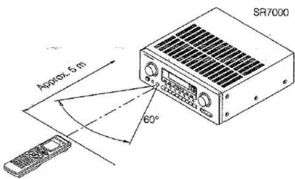
The distance between the transmitter of the remote control unit and the IR SENSOR of the SR7000 should be less than about 5 meters. If the transmitter is pointed to a direction other than the IR SENSOR or if there is an obstacle between them, remote control may not be possible.
Remote-controllable range
Remote control unit (RC7000SR)
2. Loading batteries
The life of the batteries used with the remote control unit is about 6 months with normal use. Also be sure to replace batteries earlier when you notice that they are getting weak.
(1) Remove the back cover.
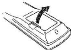
(2) Insert the new batteries (AA type) with correct (+) and (-) polarity.
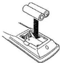
natural_image
Diagram of a mechanical lever mechanism with a cylindrical roller and base (no text or symbols)(3) Close until it clicks.
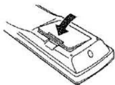
natural_image
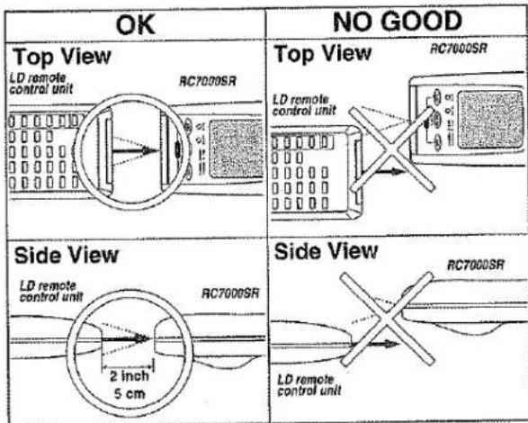
Line drawing of a mechanical component with a knob and handle (no text or symbols)The RC7000SR can learn most of the remote control codes from various equipment, it learns the full word length of the code it is receiving.
Due to the sensitivity of the receiving LED the RC7000SR may also "learn" noise from fluorescent lights, etc. which can quickly fill up the memory of the RC7000SR.
In order to maximize the memory capacity of the RC7000SR please pay close attention to the following:
(1) Aim the transmitting remote control at a direct line of sight to the RC7000SR remote receiver eye.
(2) Keep 2 inches between transmitting remote and the RC7000SR receiving eye.
SET-UP
After all components are connected, initial setup must be performed.
ON SCREEN DISPLAY MENU SYSTEM
The SR7000 incorporates an on-screen menu system, which makes various operations
possible by using the cursor (<, >, ^, v) and OK buttons on the remote handset.
The settings made with these buttons are also shown in the on-screen display.
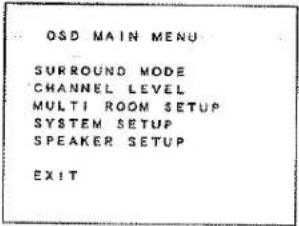
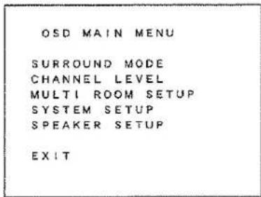
OSD MAIN MENU
SURROUND MODE
SYSTEM SETUP 1/3
SPEAKER SETUP 1/3 SPKR SIZE
CHANNEL LEVEL CONTROL
SYSTEM SETUP 2/3
SPEAKER SETUP 2/3 SPKR DISTANCE
MULTI ROOM SETUP
SYSTEM SETUP 3/3
SPEAKER SETUP 3/3 SPKR LEVEL
USD MAIN MENU
-
Press the AMP button.
-
Press any one of the cursor buttons (<, >, ^, v and OK buttons) to display the "MAIN MENU" of the on-screen display menu.
Choose a desired item in the contents with ^ or v button, and press the OK button to select.
Display will change to menu for each item.
SYSTEM SETUP
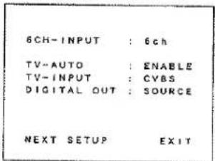
SYSTEM SETUP 1/3
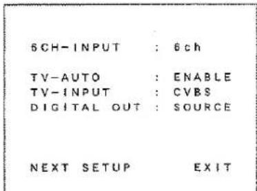
6CH. INPUT: The 6 channel input of the SR7000 can be selected to use a 6channel input or front 2channel input. Select 6channel use or 2channel use by < or > button.
TV AUTO: This product is equipped with a TV-auto ON/OFF system, which automatically turns on or off the power 1 second to 5 minutes after the TV video input signal has been sent or has been stopped.
Switch the TV AUTO ON/OFF function to enable or disable with < or > button.
To use this function, connect the TV video input to TV tuner's video output.
TV INPUT: This allows you to choose between the composite or the S-Video input for use with the TV auto function.
DIGITAL OUT: This lets you chose which digital input will be output for digital recording.

To determine each source, display the desired source and press the < or > button.
NEXT SETUP/EXIT: If you desire to continue the next setup, press the OK button on NEXT-SETUP, if you desire to exit from OSD menu system, press the OK button on EXIT.
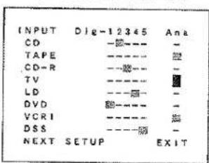
SYSTEM VINTU NV (VCLKVNTIV) (IE PINITIAL INPUT)
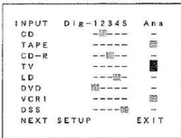
Five digital inputs can be assigned for the desired source.
Use this menu to determine which source is connected to which input.
Example;
When the digital output of a DVD player is connected to Digital 4 (Input jack) of the SR7000;
-
Move the cursor on the line of the DVD with cursor buttons ^ or v.
-
Move the cursor on "Dig 4" with cursor buttons < or >.
-
Press the OK button to chose.
-
If you desire to continue the next setup, press the OK button on NEXT-SETUP.
If you desire to exit from OSD menu system, press the OK button on EXIT.
Notes:
The TUNER and AUX are assigned to the analog input, and are prevented from selecting any digital input.
While the DTS-LD or DTS-CD is playing, this setup is not available, this is to avoid noise being generated from the analog input. Stop the LD or CD playback to setup.
The SR7000 does not switch from digital input to analog input or vice versa automatically.
In the event that both digital and analog inputs are connected to SR7000, if you desire to switch to an analog input temporarily, you can switch by pressing the A/D button ⑦.
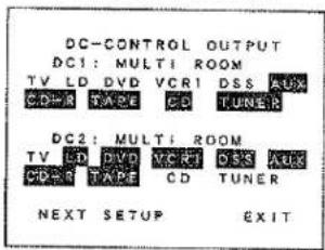
SYSTEM SETUP 3/3 (DC CONTROL OUTPUT)
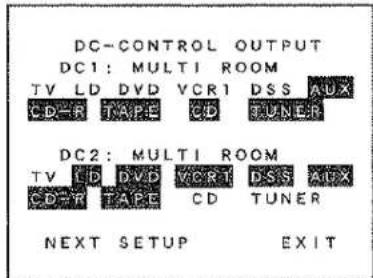
SR7000 has two DC control jacks, each one is selectable to link with input functions for the main room or multi room.
You can select MAIN ROOM, MULTI ROOM or OFF for DC1 & DC2 independently by < or > button.
And then move the cursor to select the linked input function you desired by < or > button and press OK button to chose.
SPEAKERS SETUP
The home theater system you already have installed should function provided that there are left, center and right front speakers, left and right rear/surround speakers and a subwoofer. For best results we recommend that all front speakers be of the same type, with identical or similar driver units. This will deliver smooth pans across the front sound stage as the action moves from side to side.
Your center channel speaker is very important as over 80 % of the dialog from a typical motion picture emanates from the center channel. It should possess similar sonic characteristics to the main speakers.
Rear channel speakers need not be identical to the front channel speakers, but they should be of high quality.
One of the benefits of both Dolby Digital (AC-3) and DTS is that surround channels are discrete full range, while they were frequency limited in earlier "Pro Logic" type systems.
Bass effects are an important part of home theater. For optimal enjoyment a subwoofer should be used as it is optimized for low frequency reproduction. If you have full range front speakers, however, they may be used in place of a subwoofer with proper setting of the switches in the menu system.
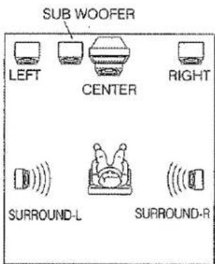
If possible, mount the surround speakers on the walls to the sides of the viewing area, 2-3 feet above seated viewers, firing straight across at each other.
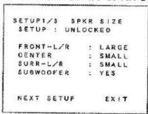
SPKR SETUP 1/3 (SPKR SIZE)
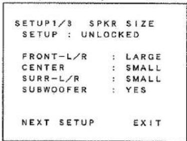
SETUP: Select "LOCKED" with < or > button in order to lock the contents of the SPKR SET UP MENU.
Then, when you want to change the contents of this setup, select "UNLOCKED".
SPKR SIZE
This menu enters the information about which type of speakers will be used for each channel.
In turn, these settings will determine which speakers receive low frequency information.
For the purpose of establishing proper bass reproduction, use the LARGE settings if the speaker being used at any position is a traditional full-range loudspeaker that is capable of reproducing sound below 100 Hz and you are not using a subwoofer.
Use the SMALL setting for smaller, frequency-limited speakers that are not able to reproduce sounds below 100Hz and you are using a subwoofer. Low frequencies will be diverted from the speaker to the subwoofer.
Note that when "small" speakers are used it is advisable to install a separate subwoofer, especially if you wish to appreciate the full impact of a good home theater soundtrack.
If the Surround speakers or Center speaker will not be used, set NONE for each speaker. The NONE will be used in
FRONT -L/R : Select the type of front speakers with < or > button.
CENTER : Select the type of center speaker with < or > button.
SURR-L/R: Select the type of surround speakers with < or > button.
SUBWOOFER: Select the subwoofer speaker yes or none with < or > button.
Notes:
The SUBWOOFER cannot be set to None when the front speakers are set to SMALL.
This speaker size setup is not effective when the SOURCE-DIRECT or 6CH. Input is selected.
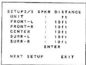
SPKR SETUP 2/3 (SPKR DISTANCE)
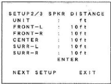
Use this parameter to specify the distance of the speaker's position from the listener.
The delay time is automatically set according to these distances.
UNITS: You can select Meters or Feet.
If you select "ft", the setting parameter will change in 1 foot steps.
If you select "m", it will change in 0.3 meter steps.
Select speaker with ^ or v button, and input each speaker's distance with < or > button.
When the input for each speaker's distance has been finished, move the cursor to ENTER and press the OK button.
NOTES :
If your are out of range, the OSD text will blink.
Placement beyond that distance is beyond the range of the automatic time delay feature.
The delay feature does not function in the SOURCE-DIRECT, 6 CH-Input modes and decoding of 96 kHz sources.
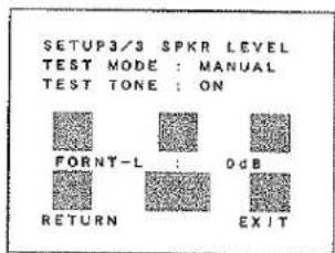
SPKR SETUP 3/3 (SPKR LEVEL)
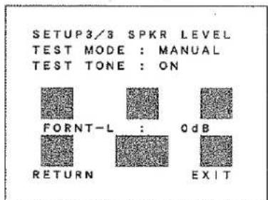
SPKR LEVEL
TEST MODE: Selects the mode for generating the test tone.
If you select AUTO, the test tone will be cycled through in a circular pattern which is Left → Center → Right → Surround Right → Surround Left → Subwoofer → Left → ... 3 seconds for each channel. If you select MANUAL, press the OK button to select the test tone channels after the "TEST TONE ON".
TEST TONE: Press the OK button, ON is indicated and the test tone starts from the front L-CH speaker.
Press the OK button again on this item. OFF is indicated and the output of the test tone will stop.
Channel: Adjust the level of test tone for each channel with the < or
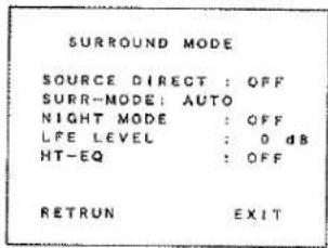
SURROUND MODE
SURROUND MODE
| SOURCE DIRECT : OFF | |
| SURR-MODE: AUTO | |
| NIGHT MODE : OFF | |
| LFE LEVEL : 0 dB | |
| HT-EQ : OFF |
| RETRUN | EXIT |
SOURCE DIRECT : Switch the source direct ON or OFF with < or > button. This bypasses the surround processing and crossover for the main speakers (front left and right will be full range and the subwoofer will be ON) Note: Surround mode cannot be changed in Source Direct mode.
SURR-MODE : Select the surround mode with < or > button.
NIGHT MODE : Switch the NIGHT MODE ON or OFF with < or > button.
Selecting the Night Mode ON is effective in Dolby Digital only, and it compresses the dynamic range.
This softens loud passages such as sudden explosions, to help prevent disturbing others late at night.
LFE LEVEL : Select the output level of the LFE signal included in the Dolby Digital signal or the DTS signal. Select 0dB, -10 dB or OFF with < or > button.
The level is ordinarily set to 0 dB except DTS-Music mode. In the DTS-Music mode, default level is set to -10 dB.
HT-EQ: Switch the HT (Home Theater) - EQ on or off with < or > button.
This mode compensates for the audio portion of a movie sounding "bright".
This equalizer is effective in AUTO, DOLBY, DTS-cinema, DTS-music and STEREO mode.
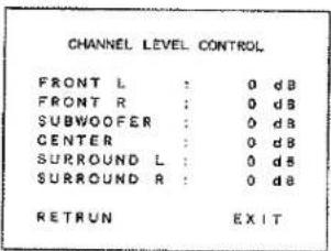
CHANNEL LEVEL CONTROL
CHANNEL LEVEL CONTROL
| FRONT L | : | 0 dB |
| FRONT R | : | 0 dB |
| SUBWOOFER | : | 0 dB |
| CENTER | : | 0 dB |
| SURROUND L | : | 0 dB |
| SURROUND R | : | 0 dB |
| RETRUN | EXIT |
Desired channels can be selected by pressing < or > button. Each channel level will be adjusted by pressing < or > button. Only the usable channels which are determined depending on the SURROUND mode, and SPEAKER SETTING are displayed.
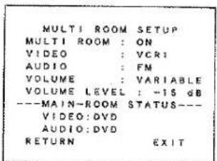
MULTI ROOM SETUP
| MULTI ROOM SETUP | |
| MULTI ROOM : ON | |
| VIDEO : VCR1 | |
| AUDIO : FM | |
| VOLUME : VARIABLE | |
| VOLUME LEVEL : -15 dB | |
| ---MAIN-ROOM STATUS--- | |
| VIDEO: DVD | |
| AUDIO: DVD | |
| RETURN | EXIT |
MULTI ROOM : To switch on the Multi-room output.
VIDEO : Select the video source of the Multi-room output.
AUDIO : Select the audio source of the Multi-room output.
VOLUME : Select whether the Multi-room output level is variable or fixed.
VOLUME LEVEL: Adjust the Multi-room output level.
MAIN ROOM STATUS : Selected input source in the main room will be displayed.
Notes:
If "VOLUME" is set to "FIXED", the multi-room output level cannot be adjusted.
You cannot transmit a digital signal using the multi-room function. Any source component that is desired to be operated in the second zone needs to have the analog outputs connected to receiver.
BASIC OPERATION
LISTENING TO THE TUNER
MANUAL TUNING
- To select the tuner as the source, press the TUNER button ⑤ on the front panel or press the TUNER button ⑧ on the remote.
- Press the TUNER button ⑤ on the front panel or press the TUNER button ⑧ on the remote to select the desired frequency band if required.
- Press the F/P button ⑯ on the front panel to display the frequency.
- Press the TUNING/PRESET ▲ or ▼ button ⑮ on the front panel or press the ^, v button ⑰ on the remote.
- If FM is selected, press the MODE button ⑦ on the front panel or select T-MOD in the tuner mode and press the ENT ⑦ button on the remote control to select the desired audio mode.
(FM) MODE BUTTON OPERATION
When "AUTO" indicator is on in the display, FM stations that broadcast in stereo will be received in stereo and the "STEREO" indicator lights.
When "AUTO" indicator is off, all the FM stations will be received in mono regardless of whether or not they are broadcasting in stereo.
AUTO TUNING (USING THE SR7000)
- Press the F/P button ⑯ on the front panel to display the frequency.
- Press the TUNING/PRESET ▲ or ▼ button ⑮ on the front panel for more than 1 second to start the Auto tuning function.
AUTO TUNING (USING THE REMOTE CONTROL UNIT)
Press ^, v button 10 for more than 1 second to start the Auto tuning function.
PRESET TUNING
With this unit you can preset up to 50 FM/AM stations in any order. For each station, you can memorize the frequency and reception mode if desired.
1-a. Manual Presetting (Using the SR7000)
- Refer to the "MANUAL TUNING" or "AUTO TUNING" section above to tune in a desired station.
- Press the MEMORY button ⑭. "MEMO" indicator starts blinking on the display.
While "MEMO" is still blinking (approx. 5 seconds), select the preset number by pressing the TUNING/PRESET ▲ or ▼ button then press the MEMORY button 14 again. - When a number has been properly input, "MEMO" indicator stops blinking and goes out.
The station is now stored in the specified preset memory location.
1-b. Manual Presetting (Using the remote unit)
-
Tune in a desired station.
-
Press the MEMO button 16
-
Enter the desired preset number with ten keypad 17
* When entering a single digit number (2, for example), either input "02" or just input "2" and wait for a few seconds.
* If a number other than 1-50 is entered by mistake, that number flashes in the display to indicate that it is invalid and the display returns to the original frequency display.
2. Auto Presetting
This function automatically scans the AM and FM band and enters all stations with sufficient signal strength into the memory.
This function is available only for SR7000.
- Select the FM band with the BAND button on the remote.
- Tune in the lowest receivable frequency.
- While pressing the MEMORY button ⑭, press the TUNING/PRESET ▲ button ⑮. Auto memory starts at this point.
-
"MEMO" will blink on the display.
-
Each time the tuner finds a station, the scanning will pause and the station will be played for five seconds. During this time, the following operations are possible:
1) The band can be changed using the BAND button on the remote.
2) The mode can be changed using the (FM) MODE button ⑰. -
If no button is pressed during this period, the current frequency is preset in location CH-2. If you wish to skip the current station, press the TUNING/PRESET ▲ or ▼ button ⑬ during this period, the current frequency is skipped and auto presetting continues.
-
Operation stops automatically when all 50 preset memory positions are filled or when auto scanning attains the highest end of all bands.
To stop the auto preset function at anytime, press the CLEAR button ⑬.
3. Recalling a Preset Station
- Press the F/P button ⑯ to change the display to preset.
- Select the desired preset station by pressing TUNING/PRESET ▲ or ▼ button ⑮ on the front panel or press CH▲ or CH▼ button ⑫ on the remote.
Note:
To directly access the preset stations using the numeric keypad, select the desired preset station by entering one or two digits using the numeric keypad 15.
To return to the Manual Tuning mode, press the F/P button ⑯.
4. Preset Scan Tuning (Using the remote control unit)
- Select the SCAN (preset scan: command page 5 in TUNER mode) by Jog Dial 6 and press the ENT button 7 on the remote control. "P-SCAN" indicator blinks in the display. (The preset station with the smallest preset number is recalled first. If no stations have been preset, CH "00" blinks in the display and the unit returns to the previous mode.)
- Preset stations are recalled in sequence (CH-1 → CH-2, etc.) for 5 seconds each. Preset numbers that do not contain stations are skipped.
- You can fast forward the preset stations by pressing the CHA button continuously.
When the desired preset station is received, cancel the preset scan operation by pressing the CH▼ button or the CLEAR button ⑬.
5. Clearing Preset Stations
You can remove preset stations from memory using the following procedure.
-
Recall the preset number to be cleared with the method described in "Recalling" a preset station.
-
Press the MEMORY button 14 on the front panel or MEMO button 16 on the remote unit, "MEMO" blinks in the display for 5 seconds. While "MEMO" is still blinking, press the CLEAR button 13 on the front panel or CLEAR button 15 on the remote unit.
-
Recall the preset number to be cleared with the method described in "Recalling" a preset station.
- Press the MEMORY button ⑭ on the front panel or MEMO button ⑯ on the remote unit, "MEMO" blinks in the display for 5 seconds. While "MEMO" is still blinking, press the CLEAR button ⑬ on the front panel or CLEAR button ⑮ on the remote unit.
"CLEAR" appears on the display to indicate that the specified preset number has been cleared.
STATION NAME LEVEL
The station name preset function allows the name of each preset channel to be entered using alphanumeric characters. The Station Name button is valid only in the tuner mode. Before station name preset operation, store stations with the preset memory operation.
- Press the MEMORY button ⑭ on the front panel or MEMO button ⑯ on the remote for more than 3 seconds.
- The left most column of the station name indicator flashes, indicating the character entry ready status.
[Operation (Using the SR7000)]
- When you press the TUNING/PRESET ▲ or ▼buttons ⑮ is turned, alphabetic and numeric characters will be displayed in the following order:

- After selecting the first character to be entered, press the MEMORY button 14. The entry in this column is fixed and the next column starts to flash. Fill the next column and press the MEMORY button 14 for more than 1 second to confirm the entry.
[Operation (Using the remote unit)]
First, press the TUNER button on the remote control unit.
(This operation is not necessary if the remote control unit has already been operated in the TUNER mode.)
- Enter the character using the ten keypad 17. For example, to enter "A":
1) Press the "1" button. "A" appears on the display column.
2) Every time the 1 button is pressed, the displayed character changes in the order: A → B → C → 1 → A...
Pressing buttons other than the "1" button cause different characters to be displayed in a similar way, so that other alphanumeric characters can be entered. To enter a blank or space, press the "9" button.
- When the desired character is displayed, press the MEMO button 16 to confirm the entry in this column and move to the next column. After having filled all of the 8 columns, press the MEMO button 16, for more than 1 second to confirm the entry.
PLAYBACK OPERATION
NORMAL PLAYBACK
- Press the POWER ON button on the remote.
- Press the FUNCTION SELECTOR button ⑤ on the front panel or press the FUNCTION button ⑧ on the remote unit to select an input source.
- Turn the SURROUND MODE SELECTOR knob ③ on the front panel or Surround mode buttons 17 in the AMP MODE on the remote unit to select the desired surround mode.
- Adjust the volume level using the VOLUME knob ④ on the front panel or press the VOL ▲ / ▼ button ⑨ on the remote. If necessary, adjust the tone, select the TRB+, TRB- and BAS+, BAS- by the Jog Dial ⑥ and press ENT button ⑦ in the AMP MODE on the remote unit.
Note:
In case of remote control operation, press one of the function buttons twice within 2 seconds to select the function.
LISTENING TO A DIFFERENT AUDIO SOURCE WHILE WATCHING A VIDEO SOURCE (Using the remote control unit)
- Select one of the following video sources TV, LD, DVD, VCR1, DSS/VCR2 or AUX.
- Next, select one of the following audio sources FM, AM, CD, TAPE, or CDR/MD.
OTHER FUNCTIONS
SETTING THE SLEEP TIMER
Set the sleep timer while the power is turned on.
- Turn the power ON and press the SLEEP button ⑩ "SLEEP" blinks on the display.
- Press the SLEEP button ⑩ the number of times to set the desired sleep time in minutes.
Each press of the SLEEP button ⑩ or changes the display in the following order:

flowchart
graph TD
    A["10"] --> B["20"]
    B --> C["30"]
    C --> D["40"]
    D --> E["50"]
    E --> F["60"]
    F --> G["70"]
    G --> H["80"]
    H --> I["90"]
    I --> J["OFF"]
    J --> A
"SLEEP" stops blinking and lights steadily. The unit will shut off in the number of minutes indicated.
* While the sleep timer is activated, the remaining time can be displayed for approximately 2 seconds by pressing the SLEEP button.
* To cancel the sleep timer, press the SLEEP button ⑩ and then press the CLEAR button ⑱.
TV AUTO ON/OFF FUNCTION
This function allows the component connected to the TV IN jack to control the power (ON/OFF) to the SR7000.
AUTO POWER ON
- Be sure TV auto mode is enable. (Refer page 11: System Setup 1/3)
- Connect your TV TUNER (etc) to the TV IN terminal. Be sure to connect the of video input.
- Turn OFF the power to the TV TUNER and the SR7000.
- Turn ON the TV TUNER and tune in a receivable station.
- When the station is received, the SR7000 turns ON and TV is selected automatically.
AUTO POWER OFF
- In the above situation, turn the TV TUNER OFF or select a channel that does not contain any broadcast.
- The SR7000 switches to STANDBY after approximately 5 minutes.
Note:
AUTO POWER OFF is canceled if the FUNCTION SELECTOR button ② is set to a source other than TV. The function reactivates when TV is selected again.
Caution:
Some TV broadcasts may cause the TV AUTO FUNCTION to be turned enable. To set this function to ENABLE/DISABLE, refer to the SETUP MENU.
MULTI ROOM SELECTOR
The Multi Room Selector is a function which allows you to listen to the same or a different source in a room other than the room in which the SR7000 is located. To use this function, a multi room remote unit and remote control signal receiver available from your Marantz dealer are necessary. The operations possible with the multi room function are explained briefly below. For details, refer to the instruction manual supplied with the multi room remote control unit and receiver.
MULTI ROOM SELECTOR OPERATION
-
Press the MULTI button ⑨. The unit enters multi room mode and the display indicates "SEL SOURCE" and flashes the "MULTI" indicator for approx. 10 seconds. In this time, you can select the input source by pressing the FUNCTION SELECTOR button ⑤ and you can set sleep timer for multi room by pressing by the SLEEP button ⑩.
-
Then, the display indicates "MULTI VOL" "VOLUME xx dB" for approx. 5 seconds. At this time, you can set the volume level of the multi room by turning the volume control knob.
MULTI ROOM SELECTOR OPERATION (USING THE MULTI ROOM REMOTE CONTROL UNIT)
-
Press the MULTI button, the POWER ON button, or select the desired source on multi room remote control unit from the MULTI ROOM. Any of these operations will put the SR7000 into multi room mode and "MULTI" will light in the display and OSD system for the TV in the multi room will be shown.
-
Press the VOL.UP or VOL.DOWN button on the multi room remote control unit to set the desired sound volume.
-
In multi room mode, the multi room remote control unit can be used in the multi room to operate the following functions. You can select a tuner preset channel and tuning up or down, and direct selection. And you can control the CD player LD player, DVD player and tape deck connected to the SR7000.
Caution:
If the main room and the secondary room are listening to the same source, the main room will have priority over controlling that source. For example, you cannot change the frequency or preset of the Tuner from a remote location if the main room is also listening to that source.
ON SCREEN DISPLAY INFOMATION
The on-screen display, which can be activated by the Main unit or remote, appears on the TV screen to show the current setting status of the SR7000.
1. GENERAL INFORMATION
When the OSD button 17 is pressed, the current setting are displayed on the TV monitor.
This display disappears automatically in about 10 seconds after the button is pressed.
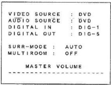
① VIDEO SOURCE:
Displays the current video source being selected with the function selector TV, LD, DVD, VCR1, DSS or AUX.
② AUDIO SOURCE:
Displays the current audio source being selected with the function selector FM, AM, CD, TAPE, CD-R, TV, LD, DVD, VCR1, DSS or AUX.
③ DIGITAL INPUT:
Displays the digital input that you are using
DIG-1, DIG-2, DIG-3, DIG-4 or DIG-5.
④ DIGITAL OUTPUT:
Displays the digital output that is being used for recording
SOURCE, DIG-1, DIG-2, DIG-3, DIG-4, DIG-5 or OFF.
⑤ SURROUND MODE:
Displays the current surround mode
AUTO, DOLBY, DTS-CINEMA, DTS-MUSIC, HALL, MATRIX, MOVIE, 5-STEREO, STEREO, S-DIRECT or 6CH INPUT.
⑥ MULTI ROOM
Displays the current status of the Multi Room function, ON or OFF.
⑦ MASTER VOLUME
Displays the current volume level.
The volume level is higher at the right of the display, and the pointer changes to "☐" at 0 dB.
Note:
The On-Screen Display signals for the main room can be output from the TV MONI composite video (RCA) output and the TV MONI, S-Video output jacks.
With some video equipment or software, the On-Screen Display characters may be distorted due to noise or tracking adjustment error.
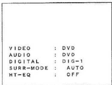
When a function selector button or surround mode button is pressed
VIDEO: Displays the current video source. When DSS/TV, LD, DVD, VCR or AUX is selected with the function selector, both AUDIO and VIDEO shows the same name.
AUDIO: Displays the current analog audio input source.
DIGITAL: Displays the current digital input source.
SURR-MODE: Displays the current Surround mode as follows; AUTO, DOLBY, DTS CINEMA, DTS MUSIC, HALL MATRIX, MOVIE, 5-STEREO, STEREO, S=DIRECT, or 6CH-INPUT.
HT-EQ : Displays the current status of the Home Theater-EQ function as ON or OFF.
3. MASTER VOLUME CONTROL
Displayed when the MASTER volume is varied or a button of the remote handset is pressed.
The box display indicates the 0 dB level with a solid box "☐".
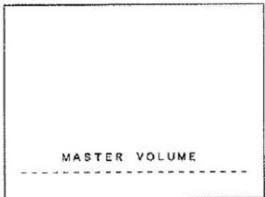
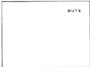
4. MUTE
When the MUTE button ⑫ is pressed on the remote control, "MUTE" will be shown on screen.
Pressing MUTE button ⑫ again will clear the display, or adjust the volume.
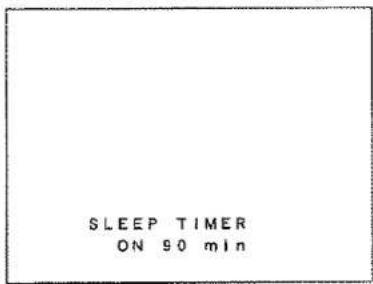
When the SLEEP button ⑩ is pressed, the setting on or off and the remaining time of the sleeptimer function are displayed.
You can change the mode between on, off and the amount of time to elapse before the unit will shut itself off by cycling the SLEEP button ⑩.
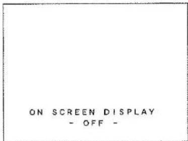
6. OSD OFF
When OSD button 17 is pressed, OSD system will be bypassed after 3 seconds.
Then there is no indication on the TV display.
Press the OSD button 17 again to activate the OSD.
REMOTE CONTROL UNIT RC7000SR
MAIN FEATURES & FUNCTIONS
• PROGRAMMABLE LEARNING FUNCTION
Can easily be programmed to learn the codes for almost any other infrared-based remote, allowing the remote control functions for many different components to be consolidated conveniently in a single unit.
- PRESET CODES
Function buttons already contain preset codes (using the RC-5/RC-6 remote control language) for other remote-controllable Marantz audio-visual component.
• LUMINOUS BUTTONS
The remote controller uses luminous buttons which store light allowing it to be used even in the dark.
• LARGE, EASY-TO-READ DISPLAY
Large LCD (liquid crystal display) displays all operating messages and other information at a glance.
• JOG DIAL
The function selected by Jog Dial (displayed on the LCD) can be operated directly by the enter button.
• MACRO CAPABILITY
Macro function allows the remote controller to be programmed to execute complex strings of multiple commands using a single keystroke.
• NAME ASSIGNMENT
Allows one to change the (displayed via the LCD) name for a command.
NAMES OF PARTS & FUNCTIONS
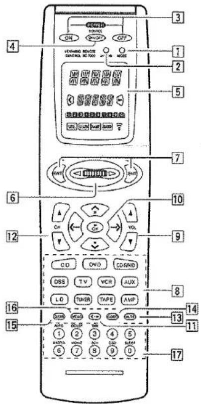
Names of Buttons & Functions
① MODE button
Used to change the operation mode of the remote controller. Pressing this button cycles the remote controller through USE → LEARN → NAME → USE, with the currently selected mode displayed on the LCD.
2 MACRO button
Used to switch the remote controller in and out of the MACRO mode, which is used to program complex operational sequences (macros), with the currently selected mode displayed on the LCD.
3 Power ON and OFF buttons
Used to turn the main system component (usually a preamplifier or receiver) ON and OFF.
4 Source ON/OFF button
Used to turn specific sources (such as DVD players, etc.) ON and OFF independently from the rest of the system.
5 LCD
Used to display information about currently selected modes and functions.
6 Jog Dial
Used to select the operation content for each source. Ten types of direct operation are possible for each of the 11 functions including LD, TV, AMP, etc. After selecting the desired function, press either of the ENT buttons [7] to transmit the signal.
ENT DULLONS
Used to execute a function selected with the Jog Dial 6
There are 2 ENT buttons, one on each side, so that the remote controller can be used just as easily with either hand.
The characters on the display can also be programmed.
8 Function buttons
Used to switch the remote controller to the command sets for specific sources (amplifier, receiver, etc.), thereby allowing a single remote controller to control up to 11 different components. To use these buttons to switch the amplifier's source, press the desired button twice within 2 seconds. The AMP button 8 is used only to switch the command set of the remote controller itself and therefore does not transmit any signal. Further, the function buttons may also be programmed to execute macros. (A macro allows a complex string of operations to be performed in series simply by pressing a single button.) One button can be programmed to learn sequences containing up to 10 commands. The following is an example of a macro sequence:
Turn the receiver ON → Switch the function to DVD → Set the Surround Mode to Dolby Digital → Switch the TV to video input → Set the DVD player to Play.
9 VOLUME ▲ up / ▼ down buttons
Used to adjust the volume on receivers and other components equipped with volume control.
10 CURSOR/TRANSPORT CONTROL buttons
Used to operate on-screen and other displays used by receivers and other components, as well as to operate the PLAY, STOP, PAUSE, NEXT, and PREVIOUS functions of each source.
11 <•▶ (CURSOR/TRANSPORT CONTROL switching) button
Used to switch the function of the CURSOR/TRANSPORT CONTROL buttons 10 between CURSOR and TRANSPORT CONTROL, with the currently selected function displayed on the LCD when the DVD, LD, or VCR functions are selected. When functions other than DVD, LD, or VCR are selected, the <•▶ button remains inactive.
12 CHANNEL ▲ up / ▼ down buttons
Used to controls the up/down function of tuner, or to cycle through the tuner presets.
13 MUTE button
Used to temporarily mute the sound of preamplifiers, receivers, etc.
14 GUIDE button
Used to call up the on-screen menus used to control DVD players, digital satellite systems (DSS), and other menu-equipped systems.
15 CLEAR button
Used to clear the contents of memory or programmed functions.
16 MEMO button
Used to program your CD player's track memory, or to enter a VCR recording program. Also can be used to provide the MEMO function included with other components in your system.
17 Ten-Key pad/Surround Mode buttons
Used to enter numeric digits, useful for finding a specific track on a CD or for tuning to a preset radio station, etc. When the function is set to AMP, it is possible to choose Surround Mode, etc.
10 Illtraled Transitmitter/Receiver Window
Used to transmit remote control signals based on beams of infrared light to system components. To ensure that these signals are properly received, make sure that this window is pointing in the general direction of the infrared receiver on the amplifier or other components. This window should also be pointed toward the source remote controller when using Programmable Learning function.
Note:
The MODE ①, MACRO ②, and <•> (CURSOR/TRANSPORT CONTROL switching) ⑪ cannot be programmed.
LCD (Liquid Crystal Display)
Information about currently selected functions and modes is displayed on the LCD. Pressing any button will call up a full display of information on the status of that function or mode. This display will disappear after approximately 1 minute, except for the Function Name indicator @, which is always displayed.
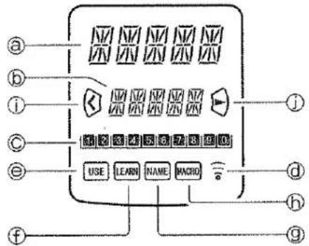
① Function Name indicator
Displays the name of the currently selected function (LD, TV, etc.) using up to 5 characters.
⑥ Command Name indicator
Displays up to 10 types of commands for each function using up to 5 characters.
© Command Page indicator
Allows confirmation of current command page. Also, when setting or transmitting macros, displays information such as the number of macro steps and the time interval between command transmissions.
© Transmission indicator
Indicates when the remote controller is transmitting a signal.
© USE indicator
For normal operation the USE Indicator is displayed.
f LEARN indicator
Indicates when the remote controller is in the LEARN mode.
⑨ NAME indicator
Indicates when the remote controller is in the NAME mode and a command name is being changed.
⑥ MACRO indicator
Indicates when the remote controller is in the MACRO mode.
① CURSOR indicator
Indicates when the CURSOR/TRANSPORT CONTROL button is in the cursor mode.
J CONTROL indicator
Indicates when the <•▶ (CURSOR/TRANSPORT CONTROL switching) 11 is in a transport control mode such as PLAY, STOP, etc.
- If the LCD flickers when a button is pressed in order to transmit a command or when in the LEARN mode, the transmission or learning is not possible. In such a case, please replace the batteries.
- This remote controller uses non-volatile memory, so that learned codes and macros will be preserved even if the batteries are removed.
BASIC OPERATION
USE MODE
The remote controller will normally be used in the USE mode. It comes preset with codes commonly used to control 11 types of components manufactured by Marantz and Philips, including DSS, DVD, TV, LD, VCR, AUX, TUNER, CD, TAPE, CD-R/MD, and AMP, as well as many others that utilize the RC-5 remote control language.
- Press one of the Function buttons ⑧ once to change to another component's commands, for example the LD button.
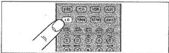
-
LD will be displayed on the LCD and the function codes will be set to operate the laser disc player, and if you double clicked the LD function button, the preamplifier or receiver's input will be changed as well.
-
Now you can operate the laser disc player. When a button is pressed, the symbol indicates that a remote code is being transmitted. is not displayed if a button for which no code has been set is pressed.
-
The Jog Dial 6 is used to select any one of up to 10 direct operations that can be performed for each of the 11 functions (LD, TV, AMP, etc.). Rotate the Jog Dial 6 to select one of these commands. The number of the current page is indicated by D-10.
Page numbers cycle up or down, for example 8 → 9 → 10 → 11 → etc. or 12 → 13 → 14 → 15 → etc. depending on which way the Jog Dial is rotated.
The last page position for any given command function is retained in the memory even if the remote controller is switched to the command function for another component. (Last Memory) If it is left for approximately 1 minute without pressing any buttons, all items on the LCD will go off except the function indicator.
Even if the display goes off, the remote controller will hold the page position and other data. The display may be activated again by pressing any button.
LEARN MODE
The remote controller is capable of learning and memorizing the remote control codes used by almost any other remote controller you may already own.
- If no commands have been programmed for a particular function button, the remote controller will transmit whatever codes have been factory preset.
- The following example shows how to program your remote controller and how to use the codes for a laser disc player (LD).
- The remote controller infrared receiver is located at the top of the remote controller.
- Use a ballpoint pen or other sharp point to press the MODE button ① until the LEARN indicator is displayed. Each time you press this button, the mode will cycle through LEARN → NAME → USE.
Stop when the LEARN indicator starts to blink.
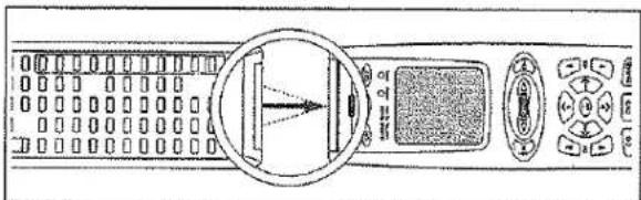
natural_image
Diagram of a computer control panel with an arrow pointing to a screen and buttons (no text or symbols visible)-
Place the laser disc's remote controller so that its infrared signal transmitter is facing the infrared signal receiver on the Marantz
-
1000 mm LD Function button
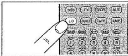
- Press the PLAY button 10 (▶ OK). The LEARN indicator changes from blinking to continuously lit.
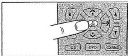
- Press and hold the PLAY button on the laser disc player's remote controller. The remote controller has finished learning the command when OK appears on the LCD @.
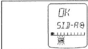
- If AGAIN appears on the LCD, some error has prevented the command from being learned. If this happens, simply repeat the procedure from step 4. - In the rare event that NG appears on the LCD, it means that the remote controller you are attempting to learn from uses special signals that cannot be learned by the Marantz remote controller.
-
Follow the same procedure to make the remote controller learn the ten-key ⑰ operation used by the laser disc player's remote controller.
-
Repeat the procedure from step 3 to have the remote controller learn the signal codes for the other components such as TV, VCR, etc.
- If no buttons are pressed for approximately 1 minute while in the LEARN mode, the remote controller automatically returns to the USE mode. - When programming the function buttons, first switch to the desired function, then press the button again.
- When you have finished programming the remote controller, use a ballpoint pen or other sharp point to once again press the MODE button ① to return it to the USE mode. The LCD displays the USE indicator, and the newly programmed codes now can be used.
If FULL is displayed on the LCD
If FULL is displayed on the LCD ① when programming in the LEARN mode, it means that the memory has become too full to hold any further codes.
If FULL is displayed no matter how many times you attempt to enter new codes, it means that the remote controller cannot accept any new codes until some of the previously learned codes are deleted to make space in the memory. Select unneeded codes for each of the Jog Dial control [6] and Function buttons [8], that show FULL and delete them from the memory.
Note:
The power ON and OFF buttons [3] can only be programmed to learn one type of code, regardless of the function button that has been selected.
HYONAMINING THE VOM BING
Let's use the example of setting 2 as the SIDE-B code for the laser disc player.
-
Use a ballpoint pen or other sharp point to press the MODE button ① until the LEARN indicator is displayed and starts to blink.
-
Place the laser disc's remote controller so that its infrared transmitter window is facing the infrared signal receiver window on the Marantz remote controller at a distance of about 5 centimeters (2 inches).
-
Press the LD Function button 8.
-
Rotate the Jog Dial ⑥ left or right until ② is displayed, then press the ENT button ⑦.
• The LEARN and NAME indicators will both be displayed.
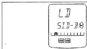
- Press the SIDE-B button on the laser disc's remote controller continuously until OK is displayed on the Marantz remote controller's LCD, indicating that the programming has been completed.
- If AGAIN appears on the LCD, some error has prevented the command from being learned. If this happens, simply repeat the procedure from step 4. When the programming has been completed, the remote controller automatically switches to the NAME mode. The left hand position on the LCD Ⓢ blinks, indicating the character in the name to be rewritten.
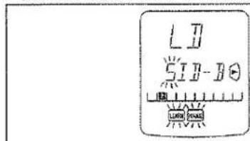
- If you do not wish to rewrite the name, simply press the OK Cursor button 10.
- if you wish to rewrite the name, input the desired characters using the ten-key pad 17. The part of the display that is being rewritten may be selected using the < and > Cursor buttons 10. When you are finished rewriting, press the OK Cursor button 10.
To simply erase already existing characters, press the 0 button to replace them with a blank space.
(Refer to next section on rewriting names)
-
Use the same procedure to program the codes for other 1-6 with the Jog Dial [6].
-
When finished programming the codes for each of the buttons, use a ballpoint pen or other sharp point to press the MODE button ① to return the remote controller to the USE mode. Once USE is displayed on the LCD, the newly memorized codes are available for use.
REWRITING NAMES
This remote controller allows the names accessible by Jog Dial control ⑥ to be rewritten with new ones of your choosing.
- Rewriting of names is performed for each individual function.
- Let's use a laser disc player as an example to show how to change the 's "SIDE-A" to "LD-A".
-
Use a ballpoint pen or other sharp point to press the MODE button ① to switch the remote controller to the NAME mode. The NAME indicator blinks,
-
Press the LD Function button 8.
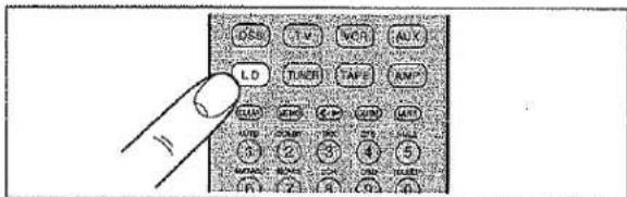
-
Use the Jog Dial 6 to select the page for which you wish to enter a new name.
-
The character on the left-hand side of the Command Name indicator on LCD Ⓞ will flash, indicating that it is the character ready to be rewritten. New characters entered will be written over the top of the current character so that the current character is erased.
Use the < and > Cursor buttons 10 to select the characters to be rewritten.
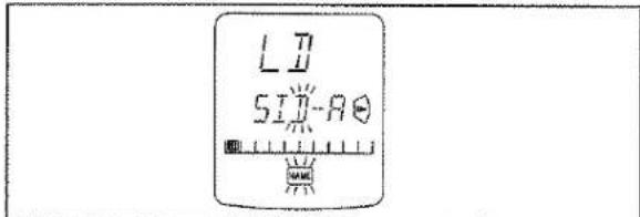
- Use the ten-key pad 17 to select the desired alphanumeric characters.
Pressing the number buttons on the ten-key pad will cycle through the alphanumeric characters as follows:
| Ten-keypad | Press, press again, press again, etc. |
| 1 | A → B → C → 1 → A |
| 2 | D → E → F → 2 → D |
| 3 | G → H → I → 3 → G |
| 4 | J → K → L → 4 → J |
| 5 | M → N → O → 5 → M |
| 6 | P → Q → R → 6 → P |
| 7 | S → T → U → 7 → S |
| 8 | V → W → X → 8 → V |
| 9 | Y → Z → / → 9 → Y |
| 0 | SPACE → + → — → , → ' → 0 → SPACE (圖) |
- For example, to enter the letter "L", press the 4-key on the ten-key pad [17] 3 times in a row to cycle from J to K to L.
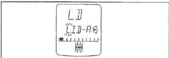
Once the desired character "L" appears, press either of the < and > Cursor buttons 10 and the L will be permanently written over the former character. Press the 0-key in order to replace unneeded extra characters with blank spaces.
- Follow the same procedure to enter "D-A". When finished, press the OK Cursor button 10. Pressing OK permanently enters the newly written characters.
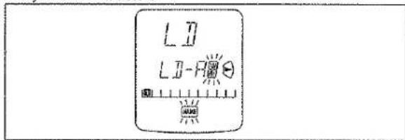
- Up to 5 alphanumeric characters may be entered in the Command Name indicator of the LCD. - To rewrite the names of the other items in the Command Name Indicator, use the Jog Dial [6] to select the desired command and repeat from step 5.
- When you are finished rewriting, use a ballpoint pen or other sharp point to press the MODE button ① to return the remote controller to the USE mode. The USE indicator is displayed on the LCD, and the newly programmed codes now can be used.
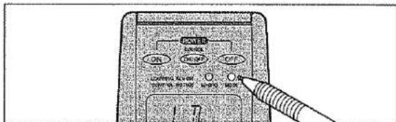
ERASING PROGRAMMED CODES
(Returning to Factory Presets)
Codes that have been programmed into the memory can be erased in 4 ways: by button(s), by function(s), by Jog Dial command, and by erasing all memory contents at once.
- Use a ballpoint pen or other sharp point to press the MODE button [1] to switch the remote controller to the LEARN mode, so that the LEARN indicator is blinking on the LCD.
Note:
Erasing of programmed codes is only possible in the LEARN mode.
2. Erasing by Button(s)
To erase the codes and names programmed for any button, press and hold the CLEAR button 15, then press the button to be erased twice. This will return the button to its factory presets or leave it empty if no factory presets are available.
Jog Dial codes may be erased in the same way, by pressing and holding the CLEAR button 15 while using the Jog Dial 6 to call up the command to be erased, then pressing one of the ENT buttons 7 on either side of the Jog Dial 6 twice. This will return the button to its factory presets or leave it empty if no factory presets are available.
To erase codes programmed for the CLEAR button 15, simply press the CLEAR button 15 continuously for 3 seconds.
As an example, let's clear the PLAY command from the laser disc player command set.
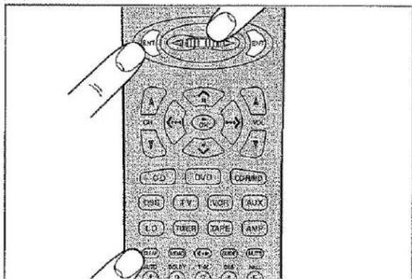
- 一、二、三、四、五、六、七、八、九、十、十一、十二、十三、十四、十五、十六、十七、十八、十九、二十、
To clear all codes and names previously set for each of the functions (LD, TV, etc.).
1) Press the function you want to erase.
2) Hold down the CLEAR button 15 and press both ENT buttons 7 at the same time. LCD 6 will display CLR?
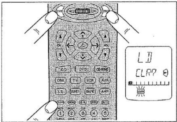
3) If you wish to continue the clearing operation, press the OK Cursor button 10. This will return all 10 commands in the Jog Dial to their factory presets, or leave them empty if no factory-presets are available. Accordingly, the LCD ⑤ will return to the factory-preset displays, or will simply be empty.
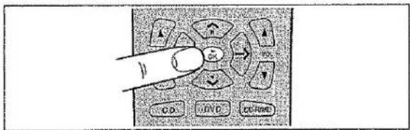
- Use a similar operation to erase the Jog Dial codes for each function.
- To cancel the memory clearing operation, do not press OK Cursor button 10 and simply touch any other button.
4. Erasing Codes by Function
To clear all codes and names previously set for each of the functions (LD, TV, etc.), press and hold the CLEAR button 15, then press the button for the function to be cleared twice. CLR? will appear on LCD ⑤. If you wish to continue the clearing operation, press the OK Cursor button 10.
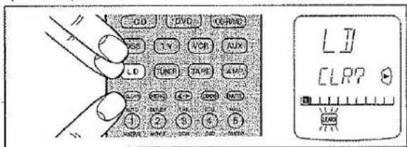
This will return the button to its factory-presets or leave it empty if no factory presets are available. Accordingly, the LCD Ⓞ will return to the factory preset displays, or will simply be empty.
• To cancel the memory clearing operation, do not press the OK Cursor button 10 and simply touch any other button.
- The codes for the <•▶ button 11 cannot be cleared.
- (1) 2017年(1月1日) 综合
To clear all the memory contents and reset all codes and names to their factory presets, press and hold the CLEAR button ⑮, and press both the power ON and OFF buttons ③ simultaneously. ACLR? will appear on LCD ⑥.
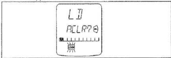
If you wish to continue the clearing operation, press the OK Cursor button 10.
This will return the entire memory to its factory-presets, or leave it empty for items for which no factory presets are available. Accordingly, the LCD will return to the factory-preset display or will simply be empty.
- To cancel the memory clearing operation, do not press the OK Cursor button 10 and simply touch any other button. After the OK Cursor button 10 is pressed, clearing the entire memory will take approximately 5 seconds.
PROGRAMMING MACROS
Macros make it possible to use a single function button to perform more complex series of operations that would normally require pressing several buttons. A single button can be programmed to perform up to 10 steps in sequence. A typical example of such a series might be as follows:
- Turn the main amplifier power ON → Switch the function to LD → Set the Surround Mode to Pro Logic → Switch the TV to video input → Set the laser disc player to PLAY.
- No signals may be transmitted during macro programming.
- The various steps that make up a macro are set initially to be sent one after another at 1 second intervals, however these intervals may be shortened to as little as 0.5 seconds or lengthened to as long as 5 seconds using the Setup mode.
-
In the macro mode, the number of steps the macro contains is displayed on LCD ©. Macros may be programmed for each of the 11 function buttons, from LD to AMP.
-
Use a ballpoint pen or other sharp point to press the MACRO button 2 until the MACRO and LEARN indicators are displayed blinking on the LCD.
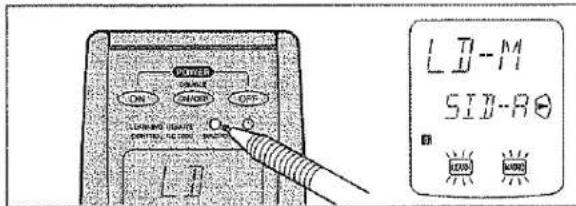
- Press the Function button 8 for which you wish to program a series of operations. In this case, let's use the example of the laser disc player.
Press the LD Function button [8]. The LCD @ will display LD-M. Characters displayed on LCD @ include the following, depending on the function button for which the macro is being programmed:
LD-M, DVD-M, TV-M, DSS-M, VCR-M, AUX-M, TUN-M, CD-M, TP-M, AMP-M, CDR-M (or MD-M for remote controller set for MD).
- If a macro has already been set for the selected function button, the LCD Ⓞ will blink. Also, the number of steps in the macro is displayed on LCD Ⓗ.
- Press the buttons for the operations you wish to program as a macro in the sequence you want the macro to program them. The name of the button pressed appears on LCD @. The number of steps in the macro is displayed on LCD © and this number increases by 1 with each button pressed.
For example, press LD, PLAY.
Each function button can be programmed to perform up to 10 steps in sequence.
- If, while programming, no buttons are pressed for approximately 1 minute, the remote controller will automatically return to normal mode, and no macro will be programmed in the memory.
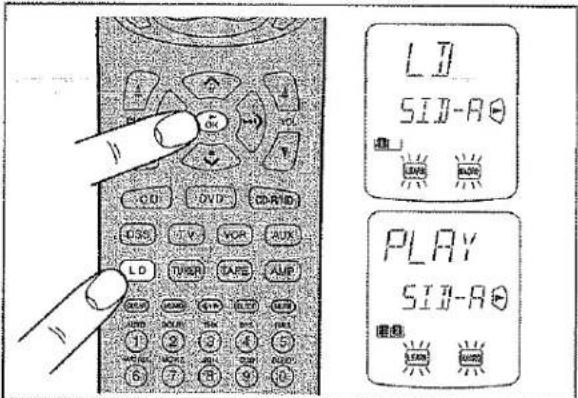
- When you are finished programming macros, use a ballpoint pen or other sharp point to press the MACRO button [7]. LCD @ will display END, and the display will return to normal.
- Macros cannot be programmed for the MODE 1, MACRO 2, <•▶ 11, VOL ▲/▼ 9, MEMO 16 or CLEAR 15 buttons.
In the macro mode it is possible to program the memory to perform macros containing up to 10 steps.
Each of the function operations (11 including CD, DVD, etc.) can be used in a macro more than once, however for all except AMP, only the first function operation will be transmitted as a signal from the remote controller. Accordingly, within a single macro, it is not possible to switch between multiple function operations. (This is to prevent the switching of the receiver function operation.) Within a macro, the second time a function operation is used, it will only be used on the remote controller itself and no signal will be transmitted to the component.
EDITING MACROS
Macros may be edited using following procedure.
- Use a ballpoint pen or other sharp point to press the MACRO button ② until the MACRO and LEARN indicators are displayed blinking on the LCD.
- Press the Function button 8 to be changed. Let's use the example of the laser disc player, by pressing the LD Function button 8.
• LD-M is displayed blinking on LCD ⓐ.
- The number of steps in the completed macro is highlighted on LCD ©. In this example there are 3 macro programs in memory.
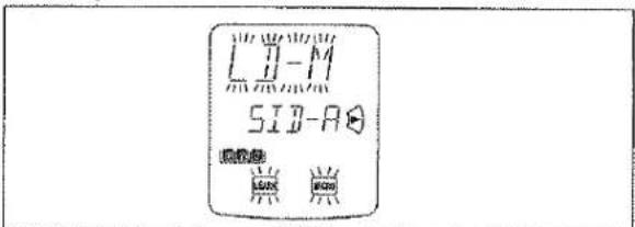
The is highlighted if no macros have been programmed, and the remote controller is ready for macro programming.
- While pressing the VOL ▲ button 9, use the ^ and v Cursor buttons 10 to call up the portion of the macro to be changed. Pressing the ^ button advances through the macro steps and pressing the v button regresses through the macro steps.
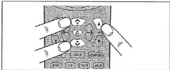
- To rewrite an existing macro step, simply press the button for the new step. The old step will be erased and rewritten with the new step.
- To insert a new step in between existing steps in a macro, after step 3 press the MEMO button 10, then press the button for the new step. The numbers of the other steps will be adjusted accordingly to accommodate the new step. Since only 10 steps may be stored in any macro, the tenth step will be erased if a step is inserted when the total number of steps is already 10.
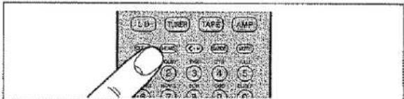
- To erase a step in a macro, after step 3 call up the number of the step to be erased and press the CLEAR button [15].
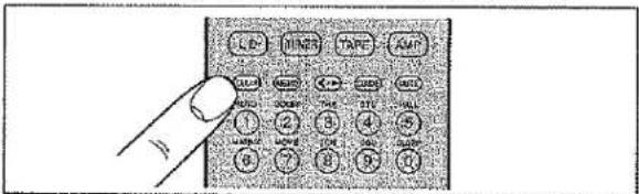
- If while editing macros no buttons are pressed for approximately 1 minute, the remote controller will automatically return to normal mode, and no macro changes will be programmed in the memory.
- When you are finished editing macros, use a ballpoint pen or other sharp point to press the MACRO button ②. END will be displayed on LCD @ and the display will return to normal.
USING MACROS
The following procedure will show how to use the function buttons for which you have programmed macros.
- Press the Function button ⑧ for the desired macro for 3 seconds. MACRO is displayed on LCD ⑨ for approximately 1 second, after which the number of steps in the macro is displayed on LCD ⑩.
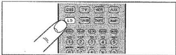
- The remote controller will do nothing if no macros are programmed. The macro steps are executed in order and the names of their buttons are displayed on the LCD. Also, the step numbers displayed on LCD © disappear as each step is executed.
- After all macro commands have been transmitted, the remote controller returns to normal mode.
- To cancel the transmission of a programmed macro, use the Cursor buttons 10 to press ■.
Example 1
Change the input source for the amplifier to CD and play the 3rd track on a CD in the CD player.
- Use a ballpoint pen or other sharp point to press the MACRO button ②, then press the CD Function button ⑧. CD-M is displayed on the LCD.
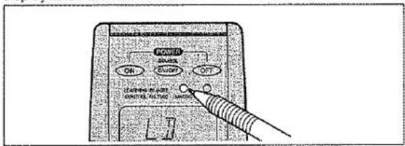
- Press CD 8, 3 17, and ▶ 10 buttons.
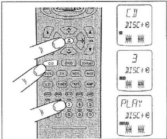
When you are finished programming the macro, use a ballpoint pen or other sharp point to press the MACRO button ②.
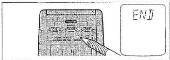
Now, execute the macro you just programmed.
- Press the CD Function button ⑧ for 3 seconds.
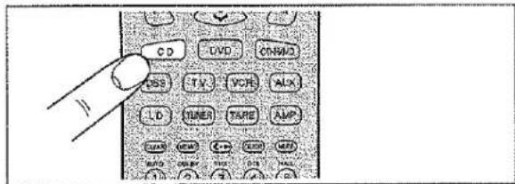
- The macro commands are transmitted to the components in order, and the names of the operations being performed are displayed on the LCD in order.
![[1] 3 PLAY](/content/2026/06/1242649/images/8eca934ebcba02ce24e25d5150b06fb9711e19ad58c5dcb2b8f66dc77320758e.jpg)
Turn the main amplifier ON → Change the amplifier's input source to LD → Set the Surround mode to DOLBY → Switch the TV to video input → Set the laser disc player to PLAY
- Use a ballpoint pen or other sharp point to press the MACRO button [2] .
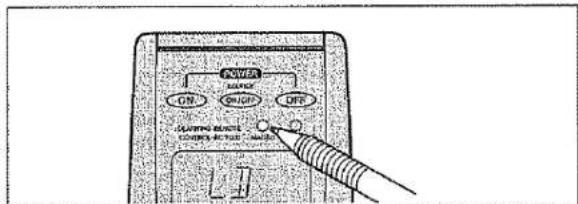
- Press the LD Function button [8].
- Here the LD Function button 8 is used as the macro button, but any function button can in fact be used.
-
To set the various steps of the macro, press the following buttons in order: POWER ON 3, LD 8, AMP* 8, 2 (DOLBY) 17, TV* 8, VIDEO (use Jog Dial 6 to select VIDEO and press ENT button 7), LD* 8, ▶ 10.
-
When you are finished programming the macro, use a ballpoint pen or other sharp point to press the MACRO button ②. The remote controller returns to normal mode.
Now, execute the macro you just programmed.
- Press the LD Function button 8 for 3 seconds.
The macro commands are transmitted in order, and the names of the operations being performed are displayed on LCD @ in order.
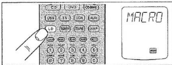
- When executing this macro, function operations AMP*, TV*, and LD* only switch the command set of the remote controller and no signal is transmitted to the component.
- To cancel the transmission of a programmed macro, use the Cursor buttons 10 to press.
CLEARING MACRO PROGRAMS
The following procedure is used to erase macros you have programmed into the remote controller's memory.
- Press and hold the CLEAR button 15, then the button for the function 8 to be cleared (in this case LD) for 3 seconds. LDCL? will appear on LCD @. If you wish to continue the clearing operation, press the OK Cursor button 10.
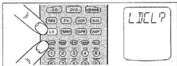
- To cancel the memory clearing operation, do not press OK Cursor button 10 and simply touch any other button.
OTHER FUNCTIONS
LUMINOUS BUTTONS
The buttons on this remote controller are designed to remain luminous in dim lighting conditions. If the buttons are no longer luminous when the remote controller is used in low light, recharge them by placing it near a fluorescent or other light source for a sufficient amount of time. This should return the buttons to their luminous condition.
SETUP
Switch the RC-5 destination or adjust the time interval between transmissions of macro operations as follows:
- While pressing the MEMO button [16] , press the OK Cursor button [10] . This will switch the remote controller to the Setup mode.
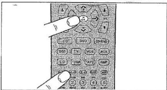
The Setup mode includes the following items, which may be accessed using the ^ and v Cursor buttons [10].
- Switch destination (version) (VER)
- Adjust time interval between transmissions of macro operations (MACRO)
VER: Switches the type of preset codes contained in the remote controller.
LCD @ displays VER, while LCD ⑥ displays either USA or REST. USA means that the CD-R/MD Function button ⑧ is set to CD-R. REST means that the CD-R/MD Function button ⑨ is set to MD.
Use the < and > Cursor buttons 10 to select the desired version, then press the OK Cursor button 10. This will finish the operation and return the LCD to its original state.
- To cancel the setting, press any button other than the Cursor buttons 10.
• To continue the setting, press the v Cursor button 10.
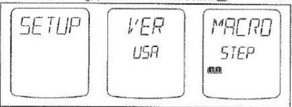
Note:
Codes that have been programmed will not be erased even if the VER setting is changed, however the NAME indicator displays associated with the Jog Dial command will be changed. Also, the Jog Dial commands for CD-R/MD functions that are contained within macros will also change.
MACRO: Adjusts the time interval between transmissions of macro operations
When the v Cursor button 10 is pressed, LCD @ displays MACRO, while LCD @ displays STEP.
One square (■) in LCD © is equivalent to an interval of 0.5 seconds, allowing intervals of up to 5 seconds to be set. The remote controller is set at the factory with an interval of 1 second, as indicated by ■□□□□□□□. Adjust the interval between transmission of operation codes using the ^ and v Cursor buttons 10, then press the OK Cursor button 10.
- To cancel the setting, press any button other than the Cursor button 10.
• To continue the setting, press the v Cursor button 10.
BATTERY LIFE
- New batteries will last about 6 months assuming an average of 30 uses per day.
Note:
The batteries shipped with the remote controller are for the purpose of checking function and may not last as long as new batteries.
NUMBER OF LEARNABLE CODES
The remote controller (RC7000SR) uses 128-Kbyte large-capacity non-volatile memory (EEPROM) and is therefore capable of learning a maximum of 330 remote control codes. This applies only to Philips RC-5 remote programming language codes, however, and depending on the type of other codes that are programmed, the remote controller can learn less than 330 codes.
JOG DIAL COMMAND FUNCTIONS LISTING
Each of the 10 Jog Dial commands on the LCD has 5 character labels attached for pre-programmed remote commands. These commands can be used with various Marantz A/V components, or other components using the Philips RC-5 remote control language.
You can easily replace the factory-supplied remote command codes with different codes from other brands of component. Most of the supplied functions apply to a wide variety of component from many companies. The following list shows the remote code assignments for the Jog Dial commands, for each of the 11 Function buttons, as supplied from the factory. You can add or replace Jog Dial commands, including re-naming them if you wish, in order to customize the remote controller for your own particular selection of A/V components.
| Function | Jog Dial command | Note |
| AMP | 1 MODE2 A/D3 ATT4 NIGHT5 MULTI6 6-DIR7 TRB+8 TRB-9 BAS+0 BAS- | selects surround modeswitches analog/digital inputswitches attenuator for analog inputselects NIGHT mode for Dolby Digitalactivates multi-room modeactivates 6-channel inputincreases trebledecreases trebleincreases bassdecreases bass |
| TUNER | 1 FM2 AM3 LW4 T-MOD5 SCAN⊗6 STM⊗7 AF⊗8 PTY⊗9 DISP⊗0 DWR | FM bandAM/MW bandLong Wave bandmono/stereo/muting mode selectorprogrammed preset channel scanselects station modeselects AF functionselects PTY functionselects display functionselects DSR wave range |
| TV | 1 A/CH2 100S3 VIDEO4 INFO5 S-PIC6 S-SUD7 S-CH8 ADV9 OSD0 MENU | alternate channel100'sselects videoinformationsmart picturesmart soundsmart channeladvanceactivates on-screen displaymenu |
| CD | 1 DISC+2 DISC-3 TEXT4 SHUFL5 REPT6 TRAY7 AMS8 TIME9 FF0 REW | CD changer next discCD changer previous discactivates text functionshuffle play functionrepeat functiontray open/closeautomatic music scantime display elapsed/remaining/totalfast forwardrewind |
| LD | 1 SID-A2 SID-B3 DISP4 AMS5 AUDIO6 RPT-A7 RPT-B8 CP/F9 EDIT0 D/CX | side Aside Bdisplay on/offautomatic music scanselects audio moderepeat A start pointrepeat B stop pointselects chapter or frameactivates edit functionselects digital audio/analog audio/CX NR |
| TAPE | 1 TP-A2 TP-B3 DIR4 TIME5 TRAY6 AMS7 REC8 PAUSE90 | selects tape deck Aselects tape deck Bauto reverse directiontime displaytray open/closeautomatic music scanrecordpause |
| Function | Jog Dial command | Note |
| VCR | 1 REC2 SLCT3 2XPLY4 SLOW5 STIL6 OTR7 AUDIO8 SKIP9 VIS+0 VIS- | recordselects TV or VCRtwice normal playback speedslower than normal playback speedstill frameone touch recordingaudio track selectorskip to next program markerVHS index search nextVHS index search previous |
| DSS/V2 | 1 DISP2 PREV3 SELECT4 AUDIO5 FAV6 ALT7 FTCH8 ANT9 REC0 OTR | brings up on-screen channel markergoes to previously selected channelselects TV or VCRaudio track selectorfavorite users and channel listsalternate audio channel, languagesbrings up on-screen channel logosselect broadcast or cable antennarecordone touch recording |
| AUX | 1 No2 No3 No4 No5 No6 No7 No8 No9 No0 No | pre code datapre code datapre code datapre code datapre code datapre code datapre code data |
| DVD | 1 OSD2 TITLE3 ZOOM4 MENU5 10+6 SETUP7 ANGLE8 SUB-T9 RESUM0 AUDIO | activates on-screen displayselects title menuzoom mode on/offselects main menudigit entry +10selects setup menuselects angleselects subtileresume functionselects audio |
For USA setups
| Function | Jog Dial command | Note |
| CDR | 1 INPUT2 INCR3 SYNC4 REC5 PROG6 TRAY7 DISP8 FINAL9 BLANK0 REPT | selects input source increments track number activates SYNCRO. recording records pause activates program mode tray open/close display mode finalizes (writes TOC) records blank activates repeat mode |
For REST setups
| Function | Jog Dial command | Note |
| MD | 1 REC2 REPT3 RANDM4 DISP5 EDIT6 EJCT7 LP8 DEL9 ENTER0 SYNC | records pauseselects repeat moderandom playselects display modeselects edit modeejectselects SP/LP modeselects deleteselects enterSYNCRO, recording |
The marked "⊗" commands are not used for SR7000.
SURROUND MODES
The SR7000 incorporates digital signal processors (DSP) which can reproduce various surround effects you experience in concert halls and movie theaters, etc. Nine Surround Modes, are provided to reproduce a variety of surround sound effects, according to the content of the source to be played.
| Surroud mode | FEATURES |
| 1. AUTO | When this mode is selected, the receiver determines whether the digital input signal is Dolby Digital, PCM-audio or DTS.Note:When a Dolby Digital or DTS signal is input, the number of channels for which the corresponding signal is encoded will be played.Inputing a Dolby Digital two channel signal with Dolby surround status automatically subjects that signal to Pro-Logic processing before play.96 Khz source material can be play back in this mode. |
| 2. STEREO | This mode bypasses all surround processingStereo program sources the left and right channels play normally when PCM-audio or analog stereo is input.With Dolby Digital and DTS sources, the 5.1 multi-channels are converted to two channel stereo. 96 Khz source material can be play back in stereo mode. |
| 3. DOLBY | This mode is used with source materials encoded in Dolby Digital and Dolby Surround.Dolby Pro Logic processing can be used on Dolby Surround encoded two channel source material (Dolby Digital two channels, PCM-audio and Analog stereo). This allows play of the four discrete channels (left, center, right and surround).Note:PCM-audio signals can be subjected to Pro Logic processing when the sampling frequency is 32 kHz, 44.1 kHz or 48 kHz.When a signal in another format is input, output will be muted. |
| 4. DTSCinemaMusic | This mode is for DTS encoded source materials such as LASER DISC, CD, and DVD.In the DTS Music mode, the LFE signal is reduced by 10 dB. With DTS music material, you should select the DTS Music mode.When playing DTS movie discs select DTS cinema mode for proper reproduction of the LFE channel. The DTS mode cannot be used when an Analog input has been selected. When the signal in another digital format is input, output will be muted. |
| 5. MOVIEHALLMATRIX | These modes provide surround effect processing from each input source material.They will produce theater, concert hall and stadium like atmospheres. Select as your taste desires.Note:PCM-audio signals can be processed in this mode when sampling frequency is 32 kHz, 44.1 kHz or 48 kHz.The 96 kHz sampling frequency mutes output. |
| 6. 5-STEREO | This mode is used to create a wider, deeper and more natural soundstage from two channel source material.This is done by feeding the left channel signal to both left front and left surround speaker and the right channel signal to both right front and right surround speaker. Additionally, the center channel reproduces a mix of the right and left channel. |
| 7. S-Direct ON | In the source direct mode, the tone control circuite and bass management configuration are bypassed for full range frequency response and the purist audio reproduction.96 Khz source material can be play back in this mode.Notes:Internal speaker size is setup to front L/R = Large, Center = Large, Surround L/R = Large and Subwoofer = yes automatically.Tone controls are also defeated. |
Caution for DTS signal:
This signal can be played when the connected DVD-player, laser-disc player or CD-player is capable of DTS-digital output. For details, refer to the player's operation manual.
Depending on the player used, DTS play may produce noise. If that happens, set the Surround mode to DTS.
Playing a DTS-CD or DTS laser disc causes the player's analog output terminal to output noise. Before playing DTS sources, be sure to connect the player's digital output to the SR7000's digital input. Be careful when connecting the output of these players to analog audio input.
Note that the SR7000 has the following restrictive functions built in to reduce noise emission as much as possible.
If DTS is selected while in the Surround mode, digital input cannot be switched to analog input. When the analog input function has been selected, Surround mode cannot be switched to DTS.
While signals from DTS-laser disc or CD are playing in another Surround mode, you cannot switch to digital input or from digital input to analog input.
Caution for 96kHz PCM-audio signal:
This signal can be played when a DVD-player or DAT-player connected to the SR7000 is capable of 96 kHz PCM output. For details, refer to the player's operation manual.
The signal can be played when STEREO or AUTO has been selected for the Surround mode.
Some DVD formatted discs featured copy protect. When use such disc, 96 kHz PCM signal is not output from the DVD player. For details, refer to the player's operation manual.
The relation between the selected surround mode and the input signal
The surround mode is selected with the surround mode buttons of the SR7000 or the remote control unit. However, the sound from the speakers depend upon the relationship between the selected surround mode and the input signal. They are as follows;
| Surround Mode | Input Signal | Output | Fluorescent indicator | LED Indicator | |||||
| LR | LS/RS | C | SW | Encoded | Mode | status (14seg) | Ch. Status | ||
| AUTO | Dolby Digital (5.1 ch) | ○ | ○ | ○ | ○ | □□ | □□ Digital, Auto | L, C, R, LS, RS, LFE | |
| Dolby Digital (2 ch) | ○ | - | - | ○ | □□ | □□ Digital, Auto | L, R | ||
| Dolby Digital (2 ch: Li/Rt) | ○ | ○ | ○ | ○ | □□ | □□ Digital, Auto, Pro Logic | L, R, S | ||
| 98kHz PCM | ○ | - | - | ○ | PCM | Stereo, Auto | 96 kHz | L, R | |
| PCM (audio) | ○ | - | - | ○ | PCM | Stereo, Auto | L, R | ||
| Analog | ○ | - | - | ○ | ANALOG | Stereo, Auto | - | ||
| DTS (5.1 ch) | ○ | ○ | ○ | ○ | DTS | dts, Auto | L, C, R, LS, RS, LFE | ||
| STEREO | Dolby Digital (5.1 ch) | ○ | - | - | ○ | □□ | STEREO | L, C, R, LS, RS, LFE | |
| Dolby Digital (2 ch) | ○ | - | - | ○ | □□ | STEREO | L, R | ||
| Dolby Digital (2 ch: Li/Rt) | ○ | - | - | ○ | □□ | STEREO | L, R, S | ||
| 96kHz PCM | ○ | - | - | - | PCM | STEREO | 96 kHz | L, R | |
| PCM (audio) | ○ | - | - | ○ | PCM | STEREO | L, R | ||
| Analog | ○ | - | - | ○ | ANALOG | STEREO | - | ||
| DTS (5.1 ch) | ○ | - | - | ○ | DTS | STEREO | L, C, R, LS, RS, LFE | ||
| DOLBY | Dolby Digital (5.1 ch) | ○ | ○ | ○ | ○ | □□ | □□ Digital | L, C, R, LS, RS, LFE | |
| Dolby Digital (2 ch) | ○ | ○ | ○ | ○ | □□ | □□ Digital, Pro Logic | L, R | ||
| Dolby Digital (2 ch: Li/Rt) | ○ | ○ | ○ | ○ | □□ | □□ Digital, Pro Logic | L, R, S | ||
| 96kHz PCM | - | - | - | - | (PCM) | □□ Digital | 96 kHz | - | |
| PCM (audio) | ○ | ○ | ○ | ○ | PCM | Pro Logic | L, R | ||
| Analog | ○ | ○ | ○ | ○ | ANALOG | Pro Logic | - | ||
| DTS (5.1 ch) | - | - | - | - | DTS | □□ Digital | - | ||
| DTS Cinema | Dolby Digital (5.1 ch) | - | - | - | - | (□□) | dts | No data | - |
| Dolby Digital (2 ch) | - | - | - | - | (□□) | dts | No data | - | |
| Dolby Digital (2 ch: Li/Rt) | - | - | - | - | (□□) | dts | No data | - | |
| 96kHz PCM | - | - | - | - | (PCM) | dts | 96 kHz | - | |
| PCM (audio) | - | - | - | - | (PCM) | dts | No data | - | |
| Analog | - | - | - | - | - | dts | No data | - | |
| DTS (5.1 ch) | ○ | ○ | ○ | ○ | DTS | dts | - | L, C, R, LS, RS, LFE | |
| DTS Music | Dolby Digital (5.1 ch) | - | - | - | - | ( ) | dts | No data | - |
| Dolby Digital (2 ch) | - | - | - | - | (□□) | dts | No data | - | |
| Dolby Digital (2 ch: Li/Rt) | - | - | - | - | (□□) | dts | No data | - | |
| 96kHz PCM | - | - | - | - | (PCM) | dis | 96 kHz | - | |
| PCM (audio) | - | - | - | - | (PCM) | dts | No data | - | |
| Analog | - | - | - | - | - | dts | No data | - | |
| DTS (5.1 ch) | ○ | ○ | ○ | ○ | DTS | dts | - | L, C, R, LS, RS, LFE. | |
| HALL MATRIX MOVIE | Dolby Digital (5.1 ch) | ○ | ○ | ○ | ○ | □□ | Movie, Hall or Matrix | - | L, C, R, LS, RS, LFE |
| Dolby Digital (2 ch) | ○ | ○ | ○ | ○ | □□ | Movie, Hall or Matrix | - | L, R | |
| Dolby Digital (2 ch: Li/Rt) | ○ | ○ | ○ | ○ | □□ | Movie, Hall or Matrix | - | L, R, S | |
| 96kHz PCM | - | - | - | - | (PCM) | Movie, Hall or Matrix | 96 kHz | - | |
| PCM (audio) | ○ | ○ | ○ | ○ | PCM | Movie, Hall or Matrix | - | L, R | |
| Analog | ○ | ○ | ○ | ○ | ANALOG | Movie, Hall or Matrix | - | - | |
| DTS (5.1 ch) | ○ | ○ | ○ | ○ | DTS | Movie, Hall or Matrix | - | L, C, R, LS, RS, LFE | |
| 6-STEREO | Dolby Digital (5.1 ch) | ○ | ○ | ○ | ○ | □□ | 5 CH | L, C, R, LS, RS, LFE | |
| Dolby Digital (2 ch) | ○ | ○ | ○ | ○ | □□ | 5 CH | L, R | ||
| Dolby Digital (2 ch: Li/Rt) | ○ | ○ | ○ | ○ | □□ | 5 CH | L, R, S | ||
| 96kHz PCM | - | - | - | - | (PCM) | 96 kHz | - | ||
| PCM (audio) | ○ | ○ | ○ | ○ | PCM | 5 CH | L, R | ||
| Analog | ○ | ○ | ○ | ○ | ANALOG | 5 CH | - | ||
| DTS (5.1 ch) | ○ | ○ | ○ | ○ | DTS | 5 CH | L, C, R, LS, RS, LFE | ||
| S-Direct | Dolby Digital (5.1 ch) | ○ | ○ | ○ | ○ | □□ | □□ Digital, Auto | S-DIRECT | L, C, R, LS, RS, LFE |
| Dolby Digital (2 ch) | ○ | - | - | - | □□ | □□ Digital, Auto | S-DIRECT | L, R | |
| Dolby Digital (2 ch: Li/Rt) | ○ | ○ | ○ | - | □□ | □□ Digital, Auto, Pro Logic | S-DIRECT | L, R, S | |
| 96kHz PCM | ○ | - | - | - | PCM | Stereo, Auto | S-DIRECT | L, R | |
| PCM (audio) | ○ | - | - | - | PCM | Stereo, Auto | S-DIRECT | L, R | |
| Analog | ○ | - | - | - | ANALOG | Stereo, Auto | S-DIRECT | - | |
| DTS (5.1 ch) | ○ | ○ | ○ | ○ | DTS | dts, Auto | S-DIRECT | L, C, R, LS, RS, LFE | |
| 6ch Input | - | ○ | ○ | ○ | ○ | - | 8CH-INPUT | ||
Note:
Dolby Digital (2 ch: Lt/Rt): signal with Dolby Surround flag Speajers are full set.
L/R : Front speaker
( ): The indicator blinks
LS/RS : Surround speaker
C : Center speaker
SW : Sub woofer speaker
TROUBLESHOOTING
In case of trouble, check the following before calling for service:
- Are the connections made properly?
- Are you operating the unit properly following user's guide?
- Are the power amplifiers and speaker working properly?
If the unit does not operate properly, check items shown in the following table.
If your trouble cannot be recovered with the remedy actions listed in the following table, malfunction of the internal circuitry is suspected; immediately unplug the power cable and contact your dealer, nearest
Marantz distributor or the Marantz Service Center in your country.
| SYMPTOM | CAUSE | REMEDY |
| SR7000 cannot be turned up. | The power plug is not connected. | Connect the power plug to the outlet. |
| No sound and picture are output even when power is on. | Mute is on.The input cable is not connected correctly.The master volume control is turned all the way down.The function selector position is wrong. | Cancel mute using the remote control unit.See the connection diagram and connect the cables correctly.Adjust the master volume.Select correct position. |
| Speaker does not outputting any sound. | The headphones are connected to the headphone jack. | Disconnect the headphones.(Speakers will not output sound when headphones are connected.) |
| Sound and pictures from other than equipment selected with the function selector. | Input cable connected incorrectly. | Connect the cable correctly by referring to the connection diagram. |
| Sound from the wrong channel is output from the speaker. | Speaker cable connected incorrectly. | Connect the cable correctly by referring to the connection diagram. |
| No sound is output from the center speaker. | The center speaker cable connection is incomplete.STEREO has been selected for Surround mode.Center = NONE has been selected in SETUP mode. | Connect the cable correctly.When STEREO is selected for Surround mode, no sound will be output from the center speaker. Set another Surround mode.Make the correct setting. |
| No sound is output from the surround speakers. | The surround speaker cable connection is incomplete.STEREO has been selected for Surround mode.Surround = NONE has been selected in SETUP mode. | Connect the cable correctly.When STEREO has been selected for Surround mode, no sound will be output from the surround speaker. Set another Surround mode.Make the correct setting. |
| No output to Sub Woofer Out. | Sub-woofer = NO has been selected in SETUP mode. | Select Sub-woofer = YES. |
| Surround mode cannot be changed. | The headphones are connected to the jack. | Disconnect the headphones.(When headphones are connected, Surround mode will be fixed to STEREO.) |
| Noise is produced during DTS-encoded CD or laser disc play. | Analog has been selected for input. | Be sure to perform digital connection, select digital input, then play. |
| DTS sources cannot be played. | Surround mode is set to DOLBY.The DVD or LD player is not DTS digital out capable. | Select other mode.Use a player which responds to DTS-digital out. |
| Player skips during play of a DTS source and produces noise. | Data error occurred during player skip. | Set Surround mode to DTS-cinema or DTS-music.. |
| A 96kHz PCM signal cannot be played. | The disc player is not 96kHz PCM digital out capable.Surround mode is set to other than STEREO and AUTO. | Use a player that responds to 96kHz PCM digital out.Set Surround mode to STEREO or AUTO. |
| A normal PCM signal (CD or laser disc) cannot be played. | Surround mode is set to DTS-cinema or DTS-music. | Select other mode. |
| A Dolby Digital signal cannot be played. | Surround mode is set to DTS-cinema or DTS-music. | Select other mode. |
| A specific channel does not produce output. | Nothing recorded on source. | Check the encoded channel on the source side. |
| FM or AM reception fails. | Antenna connection is incomplete. | Correctly connect the indoor FM and AM antennas to FM and AM antenna outlets. |
| Noise is heard during AM reception. | Reception is affected by other electrical fields. | Try changing location where the AM Indoor antenna is set up. |
| Noise is heard during FM reception. | The radio waves from the broadcasting station are weak. | Install an FM outdoor antenna. |
| Cannot get programmed station when the PRESET button is pressed. | Preset data has been erased. | Disconnecting power plug for long periods of time will erase preset data. If that happens, input the preset data again. |
| Nothing appears on the remote commander display. | Batteries are consumed. | Replace all the batteries with new ones. |
| Control with the remote control unit fails. | Batteries are consumed..Remote controller's function-key setting is wrong.The distance between this SR7000 and the remote commander is too far.Something is blocking SR7000 and the remote commander. | Replace all the batteries with new ones..Select different position from which equipment will be controlled.Move closer to this SR7000.Remove offending object. |
If the equipment malfunctions, this may be because an electrostatic discharge or AC line interference has corrupted the information in the equipment memory circuits. Therefore:
- disconnect the plug from the AC line supply
- after waiting at least three minutes, reconnect the plug to the AC line supply
- re-attempt to operate the equipment
ERROR MESSAGES
When the display indicates some error messages (e.g. ERROR **), unplug the power cable immediately. Contact your dealer, nearest Marantz distributor or the Marantz service center in your area.
Memory backup
- In case a power outage occurs or the power cord is accidentally unplugged, the SR7000 is equipped with a backup function to prevent memory data such as the preset memory from being erased.
The memory functions are backed up for up to about one week.
NOTE:
First of all keep SR7000 Standby or Powered-on more than 6 hours, to sufficient time for memory back up.
Should the operation or display seem to be abnormal, reset the unit with the following procedure.
The SR7000 is turned on, press and hold the CLEAR ⑬ and DISPLAY OFF buttons ⑪ simultaneously for 3 seconds or more.
Remember that the procedure will reset the settings of the function selector, Surround mode, delay time, TUNER PRESET etc., to their initial settings.
TECHNICAL SPECIFICATIONS
FM TUNER SECTION
| Frequency Range | 87.5 - 108.0 MHz |
| Usable Sensitivity | IHF 1.8 μV/16.4 dBf |
| Signal to Noise Ratio | Mono/Stereo 76/72 dB |
| Distortion | Mono/Stereo 0.2/0.3 % |
| Stereo Separation | 1 kHz 45 dB |
| Alternate Channel Selectivity | ± 400 kHz 60 dB |
| Image Rejection | 98 MHz 70 dB |
| Tuner Output Level | 1 kHz, ± 75 kHz Dev 800 mV |
AM TUNER SECTION
| Frequency Range | 520 - 1710 kHz |
| Signal to Noise Ratio | 50 dB |
| Usable Sensitivity | Loop 400 μV |
| Distortion | 1 kHz, 30 % Mod. 0.5 % |
| Selectivity | ± 20 kHz 70 dB |
AUDIO SECTION
| Continuous Power Output | |
| FRONT (20 Hz - 20 kHz) | 8 ohms 100W / Ch |
| Center (20 Hz - 20 kHz) | 8 ohms 100W / Ch |
| Surround (20 Hz - 20 kHz) | 8 ohms 100W / Ch |
| THD Front (20 Hz - 20 kHz) | 8 ohms 0.05 % |
| Input Sensitivity/Impedance | |
| Linear | 316 mV/ 47 Kohms |
| Signal to Noise Ratio | |
| Linear | 105 dB |
VIDEO
| Television Format | NTSC |
| Input Level/Impedance | 1 Vp-p/ 75 ohms |
| Output Level/Impedance | 1 Vp-p/ 75 ohms |
| Video Frequency Response | 5 Hz to 8 MHz (-1 dB) |
| S/N | 60 dB |
GENERAL
| Power Requirement | AC 120 V 60 Hz |
| Power Consumption (STEREO MODE RATED POWER) | 360 W |
| Dimension (MAX) | |
| Width | 17-1/4 inches (440 mm) |
| Height | 6-1/4 inches (159 mm) |
| Depth | 18-1/8 inches (460 mm) |
| Weight | 32.0 lbs (14.5 Kg) |
ACCESSORIES
| Remote Control Unit RC7000SR | 1 |
| AA-size batteries | 2 |
| FM Feeder Antenna | 1 |
| FM Antenna Converter | 1 |
| AM Loop Antenna | 1 |
Specifications subject to change without prior notice.
- maramtiz®
- WARNING
- NOTE TO CATV SYSTEM INSTALLER:
- NOTE:
- TABLE OF CONTENTS
- IMPORTANT SAFETY INSTRUCTIONS
- INTRODUCTION
- DESCRIPTION
- FEATURES
- FRONT PANEL FEATURES (SEE PAGE 1.)
- ① POWER switch and STANDBY indicator
- ② PHONES jack for stereo headphones
- Notes:
- ③ SURROUND MODE Selector knob
- ④ VOLUME control knob
- ⑤ FUNCTION SELECTOR buttons (AUDIO/VIDEO)
- ⑥ 6CH INPUT button
- ⑦ A/D (Analog/Digital) SELECTOR button
- ⑧ S. (Source) DIRECT button
- ⑨ MULTI (Multi Room) button
- ⑩ SLEEP button
- ⑪ DISPLAY OFF button
- ⑫ MUTE button
- ⑬ CLEAR button
- ⑭ MEMORY button
- ⑮ TUNING / PRESET UP and DOWN buttons
- ⑯ FREQUENCY / PRESET buttons
- ⑰ FM MODE button
- ⑱ INFRARED SENSOR window
- ⑲ ENCODED CHANNEL STATUS indicators
- ⑳ PEAK indicator
- ②1 AUX input jacks
- REAR PANEL CONNECTIONS (SEE PAGE 1.)
- Ⓐ FM antenna terminal (75 ohms)
- AM antenna and ground terminals
- ⑧ Three analog audio inputs
- CD, TAPE, and CD-R/MD
- © Two analog audio outputs for audio source equipment
- TAPE and CD-R/MD
- ① Five analog audio inputs for video source equipment
- Two analog audio outputs for video source equipment
- Five video inputs
- © Two video outputs
- H Five S-video inputs
- ① Two S-video outputs
- TV MUNI. (VIDEO/S-VIDEO) output jacks
- K MULTI ROOM REMOTE I/O terminals
- DC LEVEL control 1 & 2
- ⑧ DC control output 1 & 2
- ⑨ REMOTE CONT. IN/OUT terminals
- ◎ 6 CH INPUT jacks
- © PRE OUT jacks
- SUB WOOFER output jack
- ® Five DIGITAL inputs
- Note :
- ⑤ Two DIGITAL outputs
- ① MULTI OUT jacks (Audio)
- ① MULTI OUT jack (Video)
- SPEAKER terminals
- AC OUTLETS
- Caution:
- POWER cable
- REMOTE CONTROL DOS CONNECTIONS
- controlling the power effort of a power amplifier connected to the SR7000 through Marantz remote control
- REMOTE CONTROL UNIT RC7000SR
- POWER ON and OFF buttons
- Jog Dial
- ENT buttons
- Function buttons
- VOLUME ▲ up / ▼ down buttons
- CURSOR buttons
- MUTE button
- CLEAR button
- MEMO button
- TEN KEYPAD
- OPERATION OF REMOTE CONTROL UNIT
- Remote control
- Loading batteries
- SET-UP
- ON SCREEN DISPLAY MENU SYSTEM
- USD MAIN MENU
- SYSTEM SETUP
- SYSTEM SETUP 1/3
- Example;
- SYSTEM SETUP 3/3 (DC CONTROL OUTPUT)
- SPEAKERS SETUP
- SPKR SETUP 1/3 (SPKR SIZE)
- SPKR SIZE
- SPKR SETUP 2/3 (SPKR DISTANCE)
- NOTES :
- SPKR SETUP 3/3 (SPKR LEVEL)
- SPKR LEVEL
- SURROUND MODE
- CHANNEL LEVEL CONTROL
- MULTI ROOM SETUP
- BASIC OPERATION
- LISTENING TO THE TUNER
- MANUAL TUNING
- (FM) MODE BUTTON OPERATION
- AUTO TUNING (USING THE SR7000)
- AUTO TUNING (USING THE REMOTE CONTROL UNIT)
- PRESET TUNING
- 1-a. Manual Presetting (Using the SR7000)
- 1-b. Manual Presetting (Using the remote unit)
- Auto Presetting
- Recalling a Preset Station
- Preset Scan Tuning (Using the remote control unit)
- Clearing Preset Stations
- STATION NAME LEVEL
- [Operation (Using the SR7000)]
- [Operation (Using the remote unit)]
- PLAYBACK OPERATION
- NORMAL PLAYBACK
- LISTENING TO A DIFFERENT AUDIO SOURCE WHILE WATCHING A VIDEO SOURCE (Using the remote control unit)
- OTHER FUNCTIONS
- SETTING THE SLEEP TIMER
- TV AUTO ON/OFF FUNCTION
- AUTO POWER ON
- AUTO POWER OFF
- MULTI ROOM SELECTOR
- MULTI ROOM SELECTOR OPERATION
- MULTI ROOM SELECTOR OPERATION (USING THE MULTI ROOM REMOTE CONTROL UNIT)
- ON SCREEN DISPLAY INFOMATION
- GENERAL INFORMATION
- MASTER VOLUME CONTROL
- MUTE
- OSD OFF
- MAIN FEATURES & FUNCTIONS
- • PROGRAMMABLE LEARNING FUNCTION
- - PRESET CODES
- • LUMINOUS BUTTONS
- • LARGE, EASY-TO-READ DISPLAY
- • JOG DIAL
- • MACRO CAPABILITY
- • NAME ASSIGNMENT
- NAMES OF PARTS & FUNCTIONS
- Names of Buttons & Functions
- ① MODE button
- MACRO button
- Power ON and OFF buttons
- Source ON/OFF button
- LCD
- ENT DULLONS
- CURSOR/TRANSPORT CONTROL buttons
- 11
- CHANNEL ▲ up / ▼ down buttons
- GUIDE button
- Ten-Key pad/Surround Mode buttons
- Illtraled Transitmitter/Receiver Window
- LCD (Liquid Crystal Display)
- ① Function Name indicator
- ⑥ Command Name indicator
- © Command Page indicator
- © Transmission indicator
- © USE indicator
- f LEARN indicator
- ⑨ NAME indicator
- ⑥ MACRO indicator
- ① CURSOR indicator
- J CONTROL indicator
- USE MODE
- LEARN MODE
- If FULL is displayed on the LCD
- REWRITING NAMES
- ERASING PROGRAMMED CODES
- (Returning to Factory Presets)
- Erasing by Button(s)
- Erasing Codes by Function
- PROGRAMMING MACROS
- EDITING MACROS
- USING MACROS
- Example 1
- Now, execute the macro you just programmed.
- CLEARING MACRO PROGRAMS
- LUMINOUS BUTTONS
- SETUP
- MACRO: Adjusts the time interval between transmissions of macro operations
- BATTERY LIFE
- NUMBER OF LEARNABLE CODES
- JOG DIAL COMMAND FUNCTIONS LISTING
- SURROUND MODES
- Caution for DTS signal:
- Caution for 96kHz PCM-audio signal:
- TROUBLESHOOTING
- In case of trouble, check the following before calling for service:
- ERROR MESSAGES
- Memory backup
- TECHNICAL SPECIFICATIONS
- FM TUNER SECTION
- AM TUNER SECTION
- AUDIO SECTION
- VIDEO
- GENERAL
- ACCESSORIES
Marque : MARANTZ
Modèle : SR7000
Catégorie : Recepteur