HK560 - Recepteur HARMAN KARDON - Notice d'utilisation et mode d'emploi gratuit
Retrouvez gratuitement la notice de l'appareil HK560 HARMAN KARDON au format PDF.

Questions des utilisateurs sur HK560 HARMAN KARDON
0 question sur cet appareil. Repondez a celles que vous connaissez ou posez la votre.
Poser une nouvelle question sur cet appareil
Téléchargez la notice de votre Recepteur au format PDF gratuitement ! Retrouvez votre notice HK560 - HARMAN KARDON et reprennez votre appareil électronique en main. Sur cette page sont publiés tous les documents nécessaires à l'utilisation de votre appareil HK560 de la marque HARMAN KARDON.
MODE D'EMPLOI HK560 HARMAN KARDON
OWNER'S MANUAL
MANUEL D'UTILISATION
BEDIENUNGSANLEITUNG
ISTRUZIONI
HANDLEIDING
BRUKSANVISNING
BRUGSANVISNING
OWNER'S MANUAL
MANUEL D'UTILISATION
BEDIENUNGSANLEITUNG
ISTRUZIONI
HANDLEIDING
BRUKSANVISNING
BRUGSANVISNING
text_image
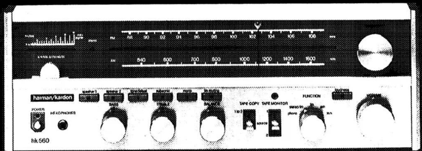
hk 560 POWER HEADPHONES hark 560 PUM 840 600 700 600 1000 1200 1400 1600 FUNCTION 9800 to pheno 3x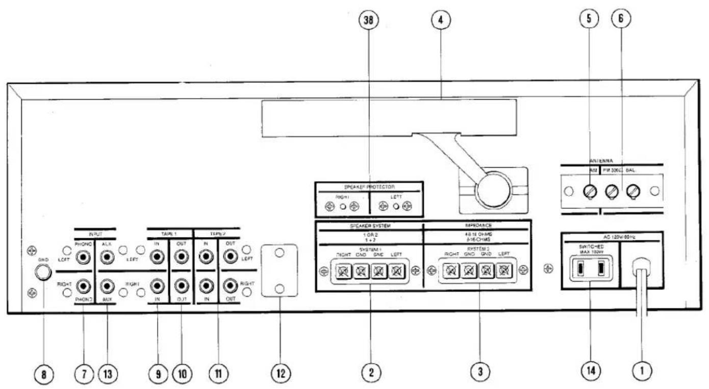
text_image
38 4 5 6 SPEEK/PRPPTECTOR RIGHT1 LEFT RMI RMI 300Ω BAL ANIONA SPEAKER SYSTEM 1 OR 2 1 + 2 48-18 OR/MS 5-16-CMS SYSTEM 1 RIGHT GND GND LEFT SYSTEM 2 RIGHT GND GND LEFT AC 120V 60Hz SHTC-HSD MAX 120V 8 7 13 9 10 11 12 2 3 14 1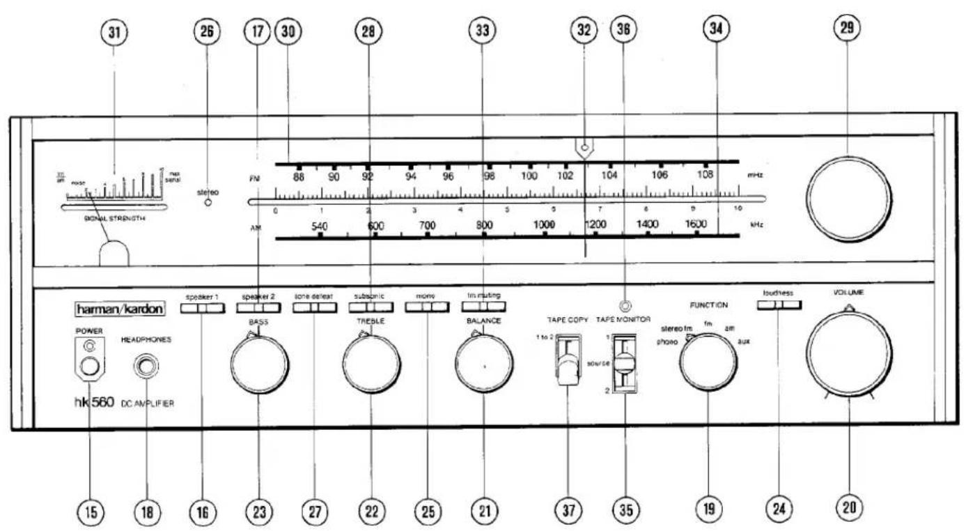
text_image
31 26 17 30 28 33 32 36 34 29 3m air noise signal s stereo FM 88 90 92 94 96 98 100 102 104 106 108 mHz 0 1 2 3 4 5 6 7 8 9 10 AM 540 600 700 800 1000 1200 1400 1600 mHz harman/kardon speaker 1 speaker 2 tone defeat subspic mon insuting TAPE COPY TAPE MONITOR FUNCTION loudness VOLUME POWER HEADPHONES SOURCE IM am hkl560 DC AMPLIFIER phone photo aux 15 18 16 23 27 22 25 21 37 35 19 24 20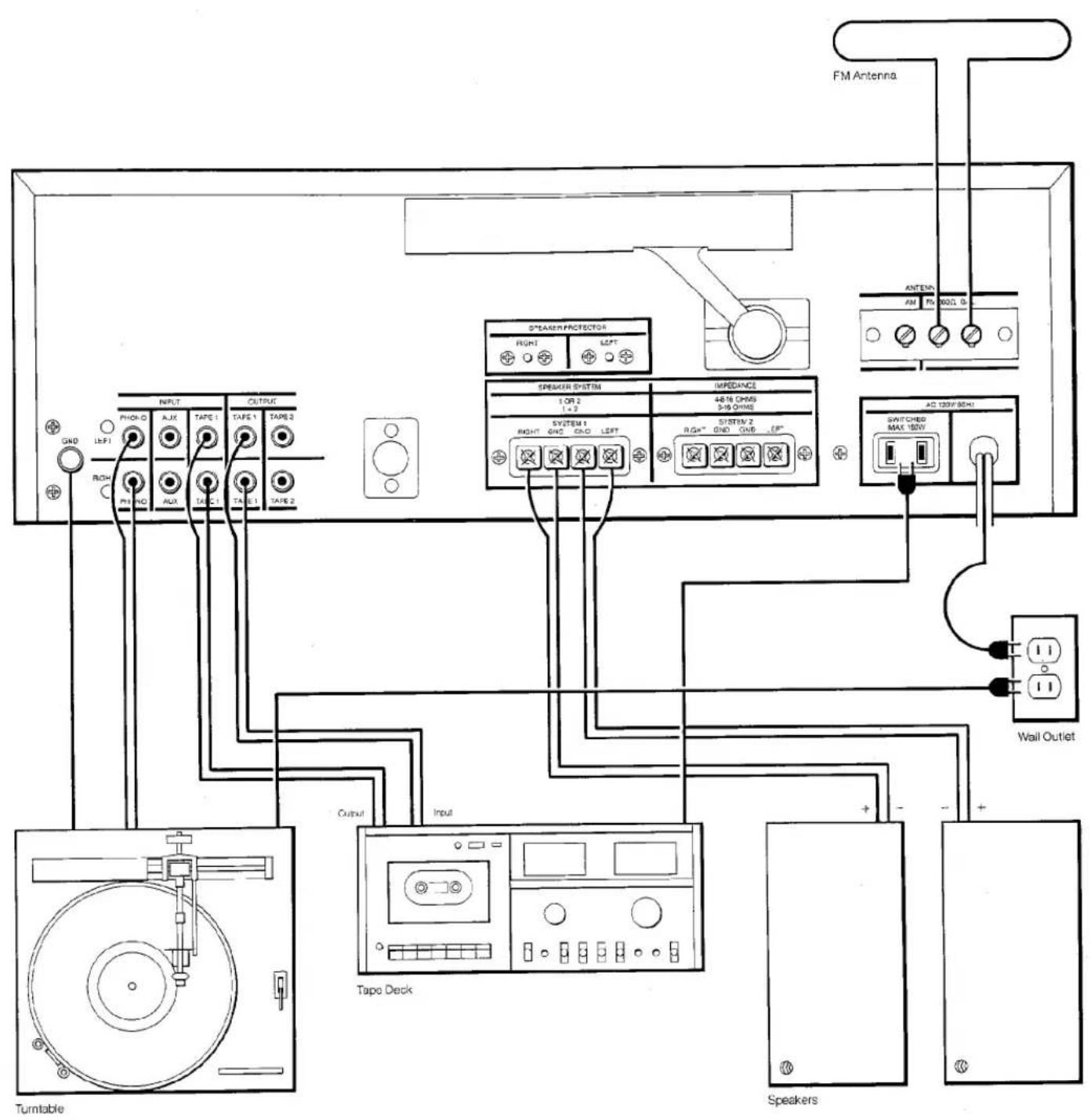
text_image
FM Antenna S*STRAWPROFECTOR RIGHT LEFT ANTEN AM RV NO. 0 SPEAKER SYSTEM 1 ON 2 1-2 44/16 CHMS 3-18 CHMS SYSTEM 1 RIGHT GND GND LEFT SYSTEM 2 RGA" GND GND -EP" AC 120V/50Hz SWITCHED MAX 120V Wall Outlet Tape Deck Turntable Input Output SpeakersOwner's manual hk560
To ensure continuing high performance, read this manual carefully before you connect and operate your hk560 receiver.
Warning: Do not mistake the ferrite loopstick AM antenna for a handle. Its bracket cannot support the unit.
CONNECTIONS
For the moment, leave the power cord (1) of the hk560 unconnected. Put the unit on the shelf or table where it will be installed. Leave enough working space so you can make connections easily.
All receivers require adequate ventilation. The hk560 should not be installed on a cushion or rug, and a minimum of two inches' clearance should be provided above and behind.
Connecting speakers
Use two-conductor stranded wire to connect your speakers to the receiver. Eighteen gauge lamp cord (zip cord) is satisfactory, but a heavier gauge (16 or 14 gauge) is preferable, especially for distances over 25 feet.
Cut two segments of wire long enough to reach each speaker. Separate the conductors at each end of the wire segments for a length of two or three inches. Then carefully remove about one-quarter inch of insulation from each free end. Twist the strands of each conductor so they are smooth and tight with no loose strands.
Lamp cord usually provides a "code" that differentiates the two conductors. A conductor may be coded by a rib, sharp corner, or indentations molded along the length of the insulation. In some cases, a thin colored thread is molded inside the insulation of one conductor. In others, one conductor is darker than the other, or the insulation of each conductor is of a different color.
Connect the bare ends of one segment of lamp cord to your right speaker as follows: Connect the coded conductor to the speaker's positive (" + ") terminal, and the uncoded conductor to negative (" - " ). (The "+" and "-" markings are in general use, although some speakers use other labeling systems, such as "1" and "2", "A" and "B" and so on.) Find the appropriate row of speaker connectors on the receiver marked SPEAKER 8-16 OHMS, SYSTEM 1 (2). Push in on the red plastic head of the connector marked RIGHT to reveal an opening beneath. Insert the bare end of the coded conductor into the opening. Release the connector. The conductor should now be locked firmly into place. Insert the uncoded conductor into the adjacent black connector marked GND.
Repeat the procedure for the left speaker, taking care to observe the coding of the conductors as described for the right speaker. If the code is followed as described, your speakers will be connected "in phase", which is important for solid bass and precise lateral location of the sound source. To connect a second pair of speakers, repeat the procedure for the right and left speakers of the second pair, using the receiver terminals marked SYSTEM 2 (3).
Connecting AM antennas
The ferrite loopstick AM antenna (4) on the rear of the hk560 can be rotated to improve the reception of distant stations. AM reception over extremely long distances can be obtained with an external "long wire" antenna, which can be connected to the AM ANTENNA terminal (5).
Connecting FM antennas
A T-shaped (dipole) FM antenna is supplied with the receiver. However, reception will be greatly improved if the receiver is connected to an outdoor FM antenna system. If you live in a fringe reception area, or if your house is situated among obstructions (such as mountains or tall buildings), you may need a powerful, directional FM antenna.
If no outdoor antenna is available, connect the lugs of the dipole (supplied with the unit) to the FM 300 Ω BAL terminals (6). The dipole can then be tacked or taped to a wall or the back of a shelf.
Connecting your turntable
The PHONO inputs (7) have been designed to operate with a high-quality magnetic phono cartridge. Do not use a ceramic phono cartridge. Turntables are supplied with their own signal cables. Consult the turntable owner's manual and determine which cable is for the left channel and which for the right. Insert the plugs of the signal cables into the jacks on the receiver marked PHONO, LEFT and RIGHT. If the turntable has a separate ground wire, connect it to the knurled lug on the receiver marked GND (8).
Tape deck connections
To connect a tape deck, first connect the line outputs of the tape deck to the left and right TAPE 1 IN jacks (9) of the receiver. Then connect the left and right TAPE 1 OUT jacks (10) of the hk560 to the line inputs of the tape. To connect a second tape deck, repeat the procedure using the TAPE 2 IN and TAPE 2 OUT jacks (11) of the hk560. A standard DIN socket (12) is provided for tape decks equipped with a DIN connector.
Time delay and signal processing
In addition to providing connections for tape decks, the TAPE IN and OUT jacks of the hk560 can be used to connect signal processors such as equalizers, noise reduction units, and dynamic range enhancers. In particular, the TAPE 2 OUT jacks can be used to connect a time delay system. In this configuration, the TAPE 2 OUT jacks provide the input for a time delay unit, which is then connected to separate amplifiers and speakers.
Auxiliary input connections
The AUX inputs (13) provide for an auxiliary source and – if desired – playback with an additional cassette, cartridge, or open-reel tape deck. A special tuner for long wave, marine, aircraft, citizen's band, or the audio output of a television set are among the components that can be connected to the AUX inputs.
AC convenience outlets\*
The AC outlet (14) on the rear panel provides connection for a turntable, tape deck, or other equipment drawing as much as 180 watts of current. The outlet is marked SWITCHED and is "live" only when the receiver is switched on.
Power connect
If you have completed all the connections you wish to make, you are now ready to place the receiver in its permanent position and plug its power line cord (1) into an AC outlet.
OPERATION
Power
The POWER switch (15) is located on the left side of the front panel, and is "on" in the depressed position.
Speaker selection and headphones
The SPEAKER 1 (16) and SPEAKER 2 (17) switches select the pair of speakers to be played. When either switch is depressed, the corresponding pair of speakers is activated. The front panel HEADPHONES jack (18) accepts headphones for personal listening. Headphones may be used simultaneously with speakers if desired.
Selecting function
Use the FUNCTION control (19) to select the desired program source.
To play records
Set the FUNCTION control (19) to PHONO. Activate your turntable, and advance the VOLUME control (20) clockwise to a comfortable level.
If you hear hum at average listening levels, turn the POWER switch (15) off and check to see that PHONO (7) and GND (8) connections are secure.
Tone controls
To increase the loudness, turn the VOLUME control (20) clockwise. The BALANCE control (21) shifts the sound to one speaker or the other.
The BASS and TREBLE controls affect the frequency balance of the program material. Their neutral positions are at 12 o'clock. Turning the TREBLE control (22) clockwise increases the high frequencies. The BASS control (23) has the same effect on the low frequencies.
When the LOUDNESS switch (24) is depressed, very high and very low frequencies are boosted at low settings of the VOLUME control. This compensates for the ear's relative insensitivity to extreme frequencies at low volume levels. The switch has little effect at VOLUME settings beyond 12 o'clock.
When the MONO switch (25) is depressed, the audio signals from left and right channels are combined, and this monophonic signal is supplied to both speakers. This switch has no effect on the FM tuner section, and the STEREO LED (26) may stay on when the switch is depressed.
Depressing the TONE DEFEAT switch (27) eliminates the action of the BASS and TREBLE controls to allow for critical evaluation of their effect.
Depressing the SUBSONIC switch (28) engages a filter to protect your speakers from in-audible low-frequency signals caused by severe record warp, acoustic feedback, or tonearm resonance effects.
FM tuning
Turn the FUNCTION control (19) of the hk560 to STEREO FM. Rotate the tuning knob (29) to tune in a station on the FM dial scale (30), calibrated from 88 to 108 megahertz. The red LED (26) labeled STEREO will glow when you are receiving a broadcast in stereo.
The tuning meter (31) indicates the relative strength of the incoming broadcast signal, the highest reading usually indicating the best reception.
A green in-tune LED (32) above the dial pointer will glow when you are tuned to the center of the broadcast channel. The illumination of the in-tune LED will usually coincide with the best reading of the tuning meter. When the two indications do not coincide, tune according to the meter.
Occasionally, an FM stereo multiplex circuit will introduce a high-frequency noise or hiss when processing a weak FM stereo broadcast. Setting the FUNCTION control (19) to FM will disengage the multiplex circuit and reduce the noise. The broadcast will be received monophonically and the red STEREO LED (26) will be off.
The hk560 incorporates an FM muting circuit to eliminate the hissing atmospheric noise you normally hear when tuning between FM stations. To engage this circuit, depress the FM MUTING switch (33).
AM tuning
Set the FUNCTION control (19) to AM and tune according to the AM dial scale (34), calibrated from 540 to 1600 kilohertz. The tuning meter (31) indicates the best reception.
Auxiliary source
You can listen to the auxiliary source that you have connected by setting the FUNCTION control (19) to AUX.
To play back tapes
The TAPE MONITOR switch (35) admits programs from any line-level source (usually a tape deck) connected to the TAPE IN jacks. When you wish to play back a tape, set the TAPE MONITOR switch to TAPE 1 or TAPE 2. When the switch is set to TAPE 1 or TAPE 2 the red LED (36) above the switch will glow. Note that as long as the switch is set to TAPE 1 or TAPE 2, no sound will be heard from any other program source, regardless of the position of the FUNCTION control.
To record tapes
The TAPE OUT jacks allow you to record program material from any source selected by the FUNCTION control. The VOLUME and BALANCE controls, and the various tone controls do not affect the signal at the TAPE OUT jacks. Hence you can change the settings of these controls without altering a tape recording in progress.
If your tape deck has a separate monitor head, you can use the TAPE MONITOR feature of the hk560 to compare the original source with the recording. Set the TAPE MONITOR switch (35) to the appropriate position (TAPE 1 or TAPE 2), and you will hear the recording a fraction of a second after it has been made. Return the TAPE MONITOR switch to SOURCE, and you will hear the original source.
The hk560 also provides the ability to record directly from one tape deck to another, while you listen to a separate source (such as records or FM) as the tape is being copied. With the TAPE COPY switch (37) set to 1 TO 2 you can copy a tape from deck 1 onto deck 2. At any time, you may listen to deck 1 by setting the TAPE MONITOR switch (35) to TAPE 1.
Speaker protection
Circuit breakers on the hk560 protect your speakers from short circuits and other conditions of excessive current. If one of your speakers stops producing sound, turn the receiver off and check the speaker connections. Make sure that no wire strands touch the wrong terminal. Locate the SPEAKER PROTECTOR pushbutton (38) for that channel. Press the button in firmly and release immediately.
Maintaining appearance
Clean the metal panel with mild, diluted detergent applied with a soft cloth or cotton swab. Never use a strong abrasive cleaner.
Remove dust or smudges from the acrylic front window with diluted glass cleaner applied with a soft cloth. Do not use a strong solvent-type cleaner or ammonia.
The hk560 is a high-quality precision instrument. If the instructions in this manual are followed thoughtfully, the receiver should provide many years of musical pleasure.
* In some countries, owing to Safety Agency Electrical requirements, these AC receptacles are covered.