StyleView Sit-Stand Combo System - Support écran plat Ergotron - Notice d'utilisation et mode d'emploi gratuit
Retrouvez gratuitement la notice de l'appareil StyleView Sit-Stand Combo System Ergotron au format PDF.

Questions des utilisateurs sur StyleView Sit-Stand Combo System Ergotron
0 question sur cet appareil. Repondez a celles que vous connaissez ou posez la votre.
Poser une nouvelle question sur cet appareil
Téléchargez la notice de votre Support écran plat au format PDF gratuitement ! Retrouvez votre notice StyleView Sit-Stand Combo System - Ergotron et reprennez votre appareil électronique en main. Sur cette page sont publiés tous les documents nécessaires à l'utilisation de votre appareil StyleView Sit-Stand Combo System de la marque Ergotron.
MODE D'EMPLOI StyleView Sit-Stand Combo System Ergotron
StyleView Sit Stand Combo System
with Small CPU Holder
For the latest User Installation Guide please visit: www.ergotron.com
English, Español, Français, Deutsch, Nederlands, Italiano, Svenska, 日本語, 汉语
Important! You will need to adjust this product after installation is complete. Make sure all your equipment is properly installed on the product before attempting adjustments. This product should move smoothly and easily through the full range of motion and stay where you set it. If movements are too easy or difficult or if product does not stay in desired positions, follow the adjustment instructions to create smooth and easy movements. Depending on your product and the adjustment, it may take many turns to notice a difference. Any time equipment is added or removed from this product, resulting in a change in the weight of the mounted load, you should repeat these adjustment steps to ensure safe and optimum operation.
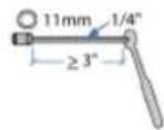
Tools Needed
Components

| A | B | C | D | E | |
| 1 | 1x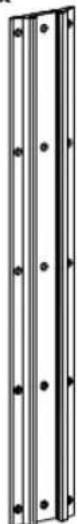 | 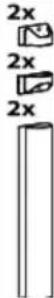 | 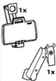 | 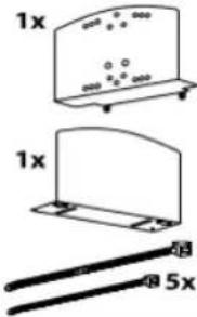 7x 7x | 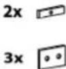 [Y7T2] [Y7T2] |
| 2 | 2x | ||||
| 3 | 1x1x | 1xM8 x 16mm1x1x1x1x1x1x1x1x1x1x1x1x1x1x1x1x1x1x1x1x1x1x1x1x1x1x1x1x1x1x1x1x1x1x1x1x1x1x1x1x1x1x1x1x1x1x1x1x1x1x1 | 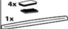 | 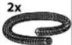 | |
| 4 | 1x 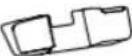 | 1x |  | ||
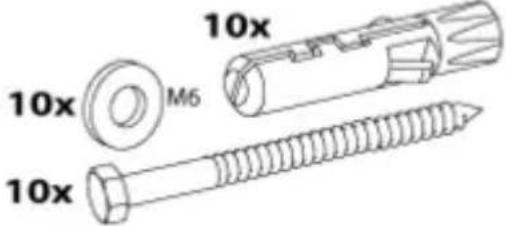
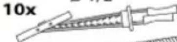
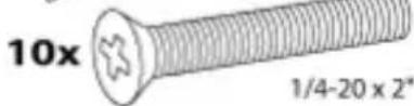
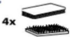
| 5 | 4x | 10x | 4x  | 4x | |
2
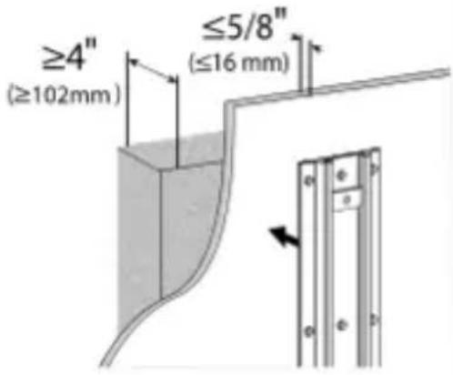
Concrete Wall Mounting
text_image
≥4" (≥102mm) ≤5/8" (≤16 mm)
Studs ≥ 25
gauge steel
text_image
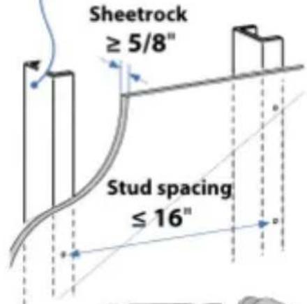
Sheetrock ≥ 5/8" Stud spacing ≤ 16"
∅ 3/8" (10 mm)
text_image
10x M6 10x 10x
∅ 1/2"

WARNING: Because surfaces vary widely and the ultimate mounting method is out of Ergotron's control, it is imperative that you consult with appropriate engineering, architectural or construction professional to ensure that your Ergotron mounting solution is mounted properly to handle applied loads.
2
Concrete Wall Mounting
text_image
≥4" (≥102mm) ≤5/8" (≤16 mm)
WARNING:
Mounting holes must be at least 3-1/8" (80mm) deep and must be located within solid concrete, not mortar or covering material. If you drill into an area of concrete that is not solid, reposition mounting holes until both anchors can be fully inserted into solid concrete!
a
text_image
x 10C
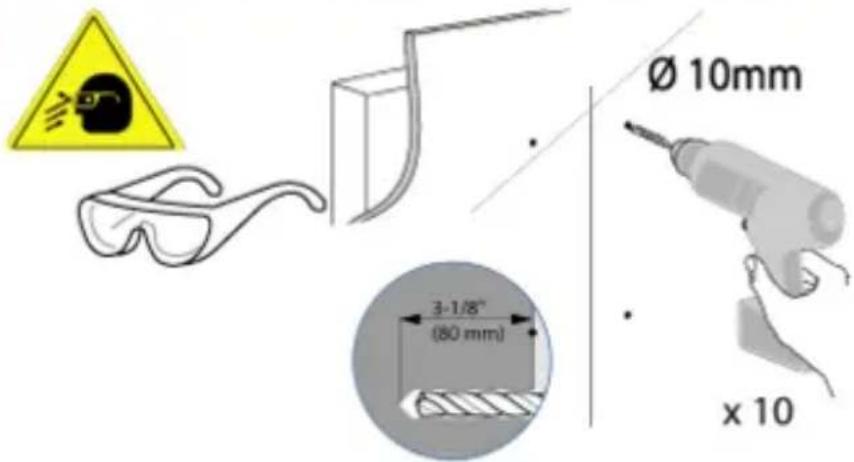
text_image
Ø 10mm 3-1/8" (80 mm) x 10
WARNING:
Anchors that are not fully set in solid concrete will not support the applied load resulting in an unstable, unsafe condition which could lead to personal injury and/or property damage. Consult a construction professional if you have any doubt about what this means in regard to your particular situation.
b
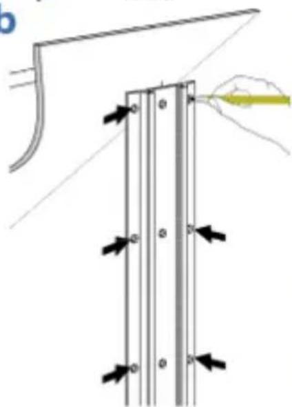
natural_image
Diagram showing a mechanical assembly with arrows indicating force or movement, no text or symbols present2
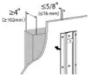
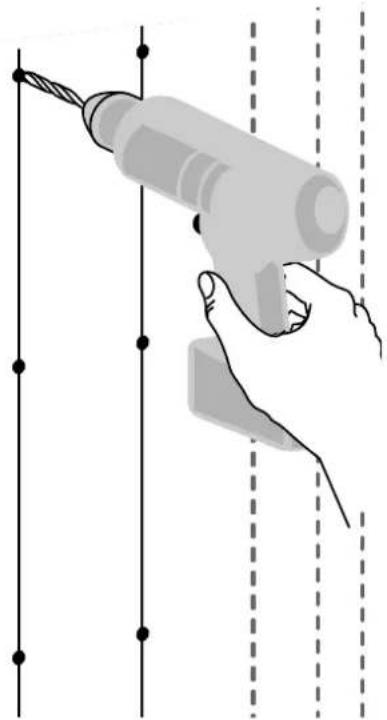
HOLLOW WALL
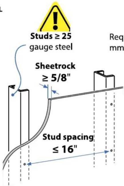
text_image
Studs ≥ 25 gauge steel Sheetrock ≥ 5/8" Stud spacing ≤ 16" Req mmRequires minimum material thickness of 5/8" (16 mm).
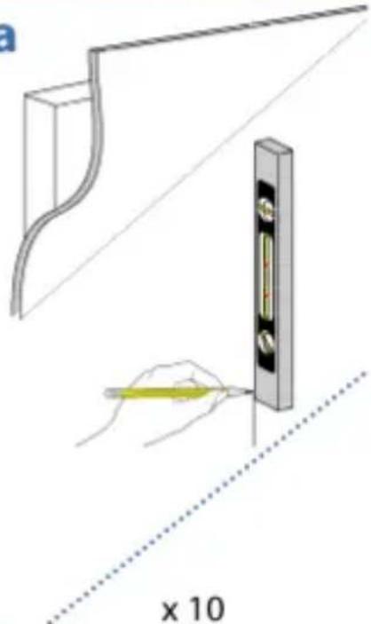
a
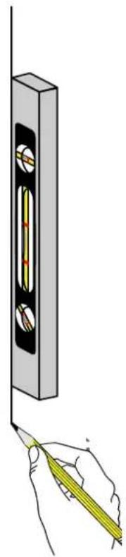
natural_image
Illustration of a hand using a tool to measure a vertical measurement on a wall, with no visible text or symbols.b

natural_image
Diagram of a vertical panel with arrows indicating force or movement, and a hand holding a pencil above it (no text or symbols present)C
10x
natural_image
Illustration of a hand using a power tool to install wires (no text or symbols present)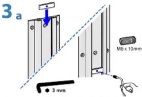
text_image
3 a M6 x 10mm 3 mm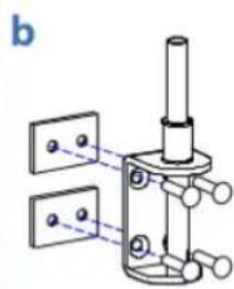
natural_image
Mechanical assembly diagram showing a piston mounted on a base with two plates nearby (no text or symbols)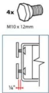
text_image
4x M10 x 12mm ¼"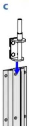
natural_image
Mechanical assembly diagram showing a bracket mounted on a metal frame with a pull arrow indicating force (no text or symbols)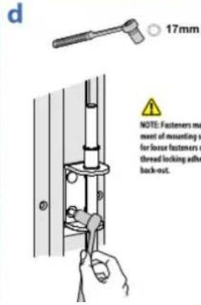
text_image
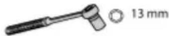
d 17mm NOTE: Fasteners must ment of mounting v for loose fasteners o thread locking adh back-out.NOTE: Fasteners may unwind due to vibration caused by movement of mounting solution over time. Inspect mounting solution for loose fasteners on a routine basis. If desired, apply a light duty thread locking adhesive to fasteners before installation to prevent back-out.
6mm
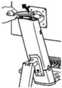
7 a
natural_image
Illustration of a hand using a tool to press or install a mechanical device (no text or symbols visible)b
natural_image
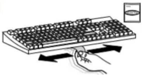
Illustration of a hand pressing down on a computer keyboard with directional arrows indicating motion (no text or symbols)C
natural_image
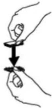
Illustration of two hands holding a small object with a downward arrow indicating motion (no text or symbols)d
e
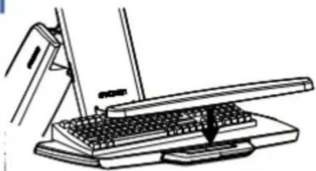
natural_image
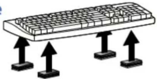
Illustration of a computer keyboard with three upward arrows pointing to its base (no text or symbols)f
natural_image
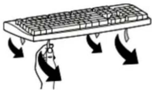
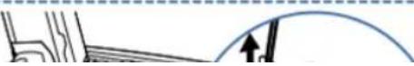
Illustration of a hand pressing down on a computer keyboard with directional arrows indicating motion (no text or symbols)g
natural_image
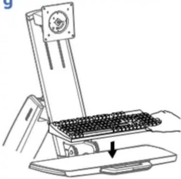
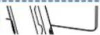
Line drawing of a mechanical device with a keyboard and base, showing a hand pressing down on a platform (no text or symbols)h
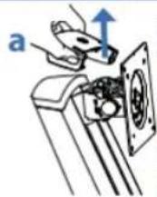
natural_image
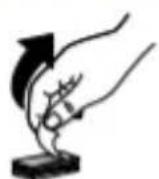
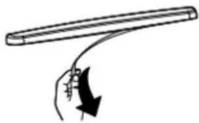
Simple line drawing of a hand holding a curved object with an arrow indicating motion (no text or symbols)i
natural_image
Line drawing of a desktop computer with a keyboard and mouse, no text or symbols presentOptional Weight Capacity Modification
Optional Weight Capacity Modification for Displays 18 - 25 lbs (8.2 - 11.3 kg) Only
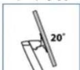
IMPORTANT: with this option display lift and tilt motion are no longer possible. To accommodate extra weight, the display is fixed at one of three heights (spaced 2.5" (64 mm) apart), and display tilt is fixed at 20°. If mounting a display 18 lbs (8.2 kg) or less, skip to next page.
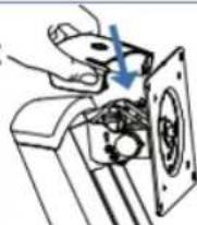
i
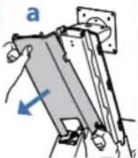
natural_image
Diagram of a mechanical assembly with labeled component 'a' and directional arrow (no text or symbols beyond label)b
1x M4 x 8mm
text_image
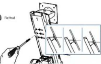
Flat Headii
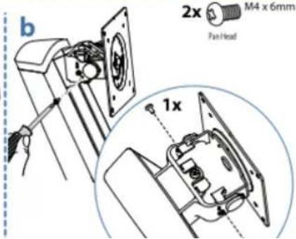
text_image
b 2x M4 x 6mm Fan Head 1x
M4 x 6mm
C
8
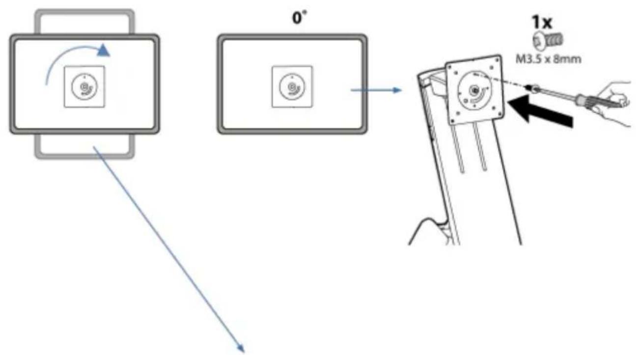
text_image
0° 1x M3.5 x 8mm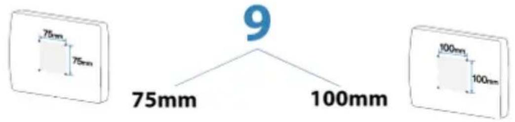
text_image
75mm 75mm 9 75mm 100mm 100mm 100mm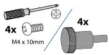
text_image
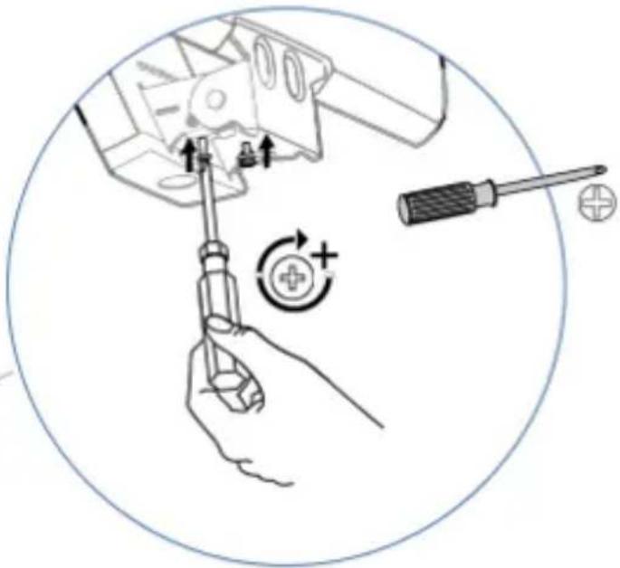
4x M4 x 10mm 4x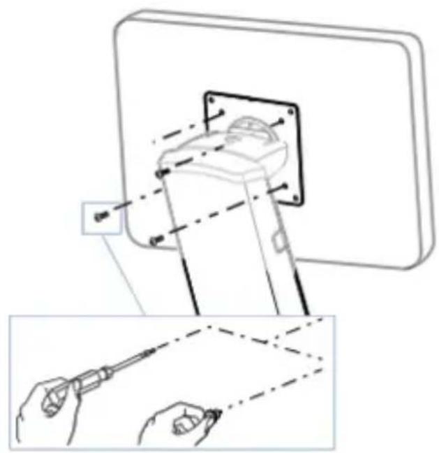
natural_image
Technical illustration of a screwdriver inserted into a component, showing tool path and alignment (no text or symbols)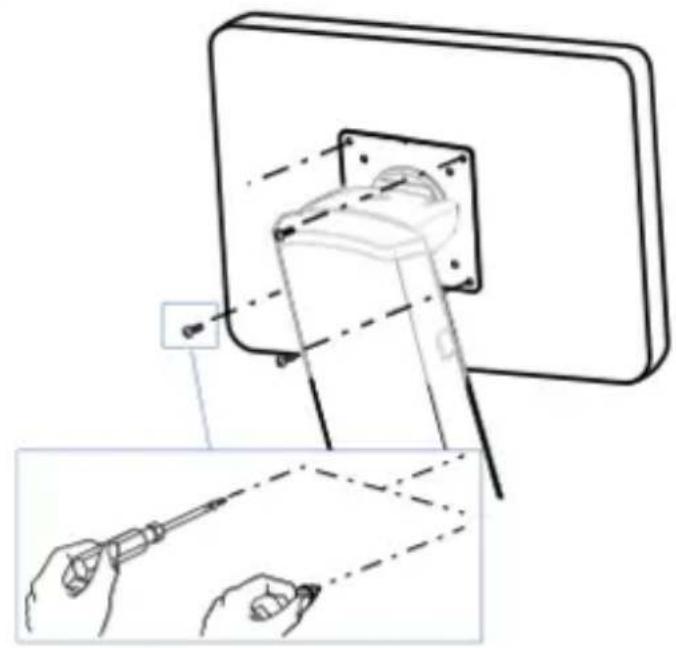
natural_image
Technical line drawing showing a mechanical assembly with tool application, including a close-up of a tool inserted into a component (no text or symbols present)10

NOTE: Leave enough slack in cable to allow full range of motion.

Caution:
To avoid the potential to pinch cables it is important to follow the cable routing instructions in this manual. Failure to follow these instructions may result in equipment damage or personal injury.
a
natural_image
Mechanical assembly diagram showing a lever mechanism with no visible text or symbolsb
natural_image
Mechanical assembly diagram showing a clamping mechanism with no visible text or symbolsC
natural_image
Illustration of a hand using a tool to adjust or install a mechanical component (no text or symbols visible)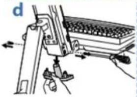
natural_image
Mechanical assembly diagram showing a lever mechanism with weights and arrows indicating motion (no text or symbols)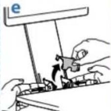
natural_image
Illustration of hands assembling a mechanical component with a hanging scale and a small object (no text or symbols)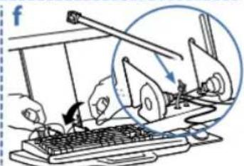
text_image
fg
h
text_image
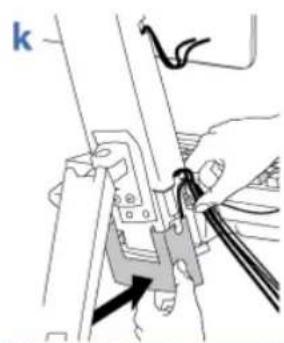
k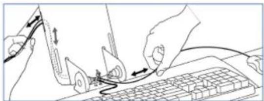
natural_image
Line drawing of hands connecting a keyboard to a mouse on a keyboard, with no text or symbols present.NOTE: Make sure cables can slide in and out through covers and cable channels.
natural_image
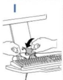
Illustration of hands using a computer to interact with a keyboard (no text or symbols visible)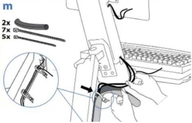
text_image
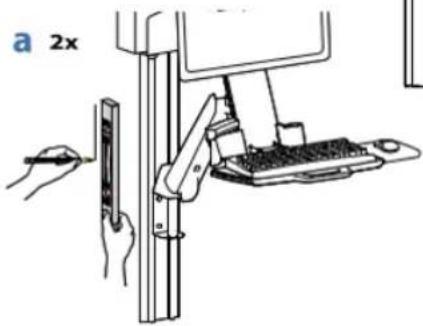
m 2x 7x 5x13
4x

4x

2x


2x
Ø 7/32" (xx mm) .21875
!
CAUTION: Make sure there is enough clearance between back of mounted component and cable channel. Failure to allow clearance space may result in personal injury and equipment damage.
text_image
a 2xb
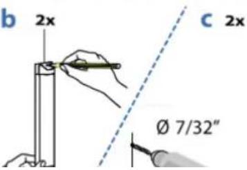
text_image
b 2x c 2x Ø 7/32"C 2x
d 2x


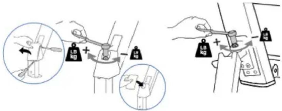
Adjustment Step
Important! You will need to adjust this product after installation is complete. Make sure all your equipment is properly installed on the product before attempting adjustments. This product should move smoothly and easily through the full range of motion and stay where you set it. If movements are too easy or difficult or if product does not stay in desired positions, follow the adjustment instructions to create smooth and easy movements. Depending on your product and the adjustment, it may take many turns to notice a difference. Any time equipment is added or removed from this product, resulting in a change in the weight of the mounted load, you should repeat these adjustment steps to ensure safe and optimum operation.
Increase Lift Strength
If the mounted weight is too heavy or this product does not stay up when raised, then you'll need to increase Lift Strength:
Decrease Lift Strength
If the mounted weight is too light or this product does not stay down when lowered, then you'll need to decrease Lift Strength:

Lift - Up and down
natural_image
Simple line drawing of a mechanical assembly with an upward arrow indicating motion (no text or symbols)

Increase Lift Strength
If the mounted weight is too heavy or this product does not stay up when raised, then you'll need to increase Lift Strength:


Decrease Lift Strength
If the mounted weight is too light or this product does not stay down when lowered, then you'll need to decrease Lift Strength:
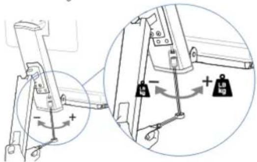
text_image
Diagram showing mechanical assembly with labeled components and directional arrows indicating motion or force directions


Increase Friction

Arm Swing - Side-to-side
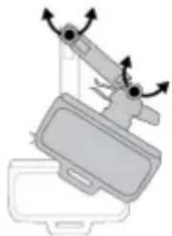
natural_image
Diagram of a mechanical device with rotating arms and a base plate (no text or symbols)
Increase Friction
If this product moves too easily, then you'll need to increase friction:
Decrease Friction
If this product is too difficult to move, then you'll need to decrease friction:
text_image
Diagram illustrating how a tool adjusts the weight of a device, showing two states: one with a lever and another with a handle.
text_image
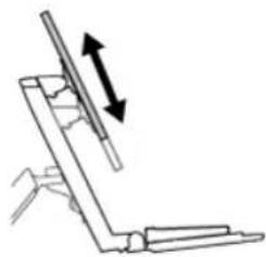
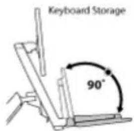
Keyboard Storage 90°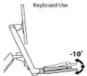
text_image
Keyboard Use -10°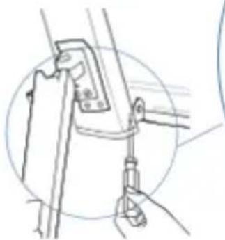
natural_image
Line drawing of a mechanical clamp or bracket assembly (no text or symbols)Set Keyboard Angle to -10 degrees
natural_image
Illustration of a hand using a screwdriver to adjust electrical components, with no visible text or symbols.© 2014 Ergotron, Inc. All rights reserved.