
LUX T10-1143SA - Thermostat AEG-ELECTROLUX - Notice d'utilisation et mode d'emploi gratuit
Retrouvez gratuitement la notice de l'appareil LUX T10-1143SA AEG-ELECTROLUX au format PDF.
| Type de produit | Thermostat |
| Marque | AEG-ELECTROLUX |
| Modèle | LUX T10-1143SA |
| Alimentation | 24 Vca (max 30 Vca) |
| Action du contact | Contact ouvert |
| Anticipateur (chauffage/refroidissement) | Fixe 24 Vca |
| Plage de température | 10 °C à 32 °C (50 °F à 90 °F) |
| Fonctions principales | Chauffage, refroidissement, ventilation continue ou automatique |
| Réglage anticipateur | Curseur long (réglage usine 0,6 A ; 1,2 A pour millivolt) |
| Installation | Sur mur intérieur, à 1,5 m du sol, à l'abri des sources de chaleur et courants d'air |
| Outils requis | Tournevis, perceuse, foret 5 mm, niveau, crayon |
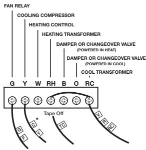
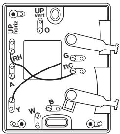
| Raccordement | Jusqu'à 6 fils : G, Y, W, RH, B, O, RC ; schémas inclus |
| Nombre de fils possibles | 2 à 6 fils |
| Compatibilité | Systèmes 24 Vca chauffage, refroidissement, pompe à chaleur |
| Garantie | 3 ans (pièces et main-d'œuvre) |
| Recyclage | Sans mercure ; suivre les consignes locales pour l'élimination |
| Entretien | Nettoyer avec un chiffon sec ; ne pas utiliser de produits liquides |
| Sécurité | Ne pas utiliser avec des compresseurs sans temporisation ; couper l'alimentation avant installation |
| Dimensions (approx.) | Environ 80 x 80 x 30 mm (sans la plaque murale) |
| Poids (approx.) | Environ 150 g |
FOIRE AUX QUESTIONS - LUX T10-1143SA AEG-ELECTROLUX
Questions des utilisateurs sur LUX T10-1143SA AEG-ELECTROLUX
0 question sur cet appareil. Repondez a celles que vous connaissez ou posez la votre.
Poser une nouvelle question sur cet appareil
Téléchargez la notice de votre Thermostat au format PDF gratuitement ! Retrouvez votre notice LUX T10-1143SA - AEG-ELECTROLUX et reprennez votre appareil électronique en main. Sur cette page sont publiés tous les documents nécessaires à l'utilisation de votre appareil LUX T10-1143SA de la marque AEG-ELECTROLUX.
MODE D'EMPLOI LUX T10-1143SA AEG-ELECTROLUX
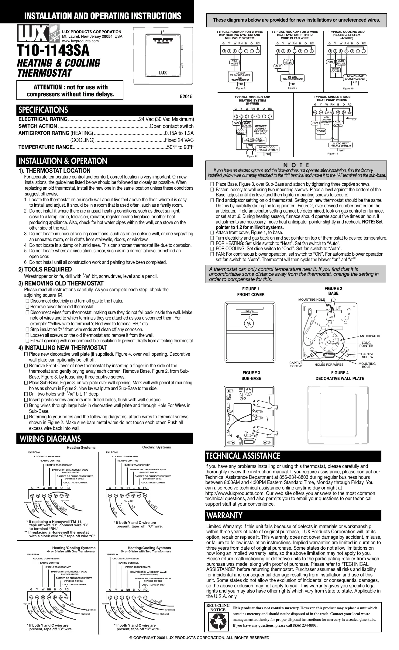
ATTENTION : not for use with compressors without time delays.
52015
SPECIFICATIONS
ELECTRICAL RATING
.24 Vac (30 Vac Maximum)
SWITCH ACTION
.Open contact switch
ANTICIPATOR RATING (HEATING)
(COOLING)
.Fixed 24 VAC
TEMPERATURE RANGE
.50°F to 90°F
INSTALLATION & OPERATION
1). THERMOSTAT LOCATION
For accurate temperature control and comfort, correct location is very important. On new installations, the guidelines listed below should be followed as closely as possible. When replacing an old thermostat, install the new one in the same location unless these conditions suggest otherwise.
1. Locate the thermostat on an inside wall about five feet above the floor, where it is easy to install and adjust. It should be in a room that is used often, such as a family room.
2. Do not install it where there are unusual heating conditions, such as direct sunlight, close to a lamp, radio, television, radiator, register, near a fireplace, or other heat producing appliance. Also, check for hot water pipes within the wall, or a stove on the other side of the wall.
3. Do not locate in unusual cooling conditions, such as on an outside wall, or one separating an unheated room, or in drafts from stairwells, doors, or windows.
4. Do not locate in a damp or humid area. This can shorten thermostat life due to corrosion.
5. Do not locate where air circulation is poor, such as in a corner, alcove, or behind an open door.
6. Do not install until all construction work and painting have been completed.
2) TOOLS REQUIRED
Wirestripper or knife, drill with 316 " bit, screwdriver, level and a pencil.
3) REMOVING OLD THERMOSTAT
Please read all instructions carefully. As you complete each step, check the adjoining square ☑.
☐ Disconnect electricity and turn off gas to the heater.
□ Remove cover from old thermostat.
☐ Disconnect wires from thermostat, making sure they do not fall back inside the wall. Make note of wires and to which terminals they are attached as you disconnect them. For example: "Yellow wire to terminal Y, Red wire to terminal RH," etc.
☐ Strip insulation 38 " from wire ends and clean off any corrosion.
□ Loosen all screws on the old thermostat and remove it from the wall.
☐ Fill wall opening with non-combustible insulation to prevent drafts from affecting thermostat.
4) INSTALLING NEW THERMOSTAT
☐ Place new decorative wall plate (if supplied), Figure 4, over wall opening. Decorative wall plate can optionally be left off.
☐ Remove Front Cover of new thermostat by inserting a finger in the side of the thermostat and gently prying away each corner. Remove Base, Figure 2, from Sub-Base, Figure 3, by loosening three captive screws.
☐ Place Sub-Base, Figure 3, on wallplate over wall opening. Mark wall with pencil at mounting holes as shown in Figure 2. Now lay wallplate and Sub-Base to the side.
□ Drill two holes with 316 " bit, 1" deep.
☐ Insert plastic screw anchors into drilled holes, flush with wall surface.
☐ Bring wires through large hole in decorative wall plate and through Hole For Wires in Sub-Base.
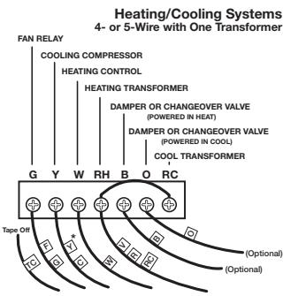
☐ Referring to your notes and the following diagrams, attach wires to terminal screws shown in Figure 2. Make sure bare metal wires do not touch each other. Push all excess wire back into wall.
WIRING DIAGRAMS
Heating Systems
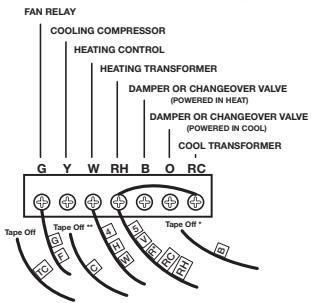
* If replacing a Honeywell TM-11, tape off wire "R"; connect wire "B" to terminal "RH."
** If replacing a Honeywell thermostat with a clock wire "C," tape off wire "C"
* If both Y and C wire are present, tape off "C" wire.
Cooling Systems
* If both Y and C wire are present, tape off "C" wire.
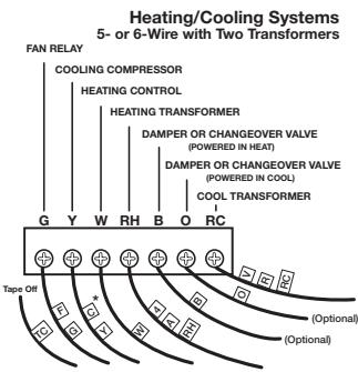
* If both Y and C wire are present, tape off "C" wire.
flowchart
graph TD
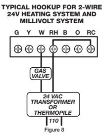
A["Typical Hookup for 2-Wire 24V HEATING SYSTEM AND MILLIVOLT SYSTEM"] --> B["G Y W RH B O RC"]
B --> C["Gas Valve"]
C --> D["24 VAC TRANSFORMER OR THERMOPILE"]
D --> E["Figure 8"]
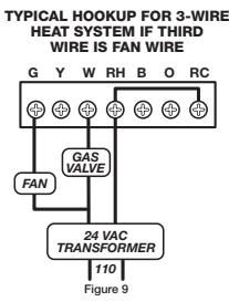
flowchart
graph TD
    A["110"] --> B["24 VAC TRANSFORMER"]
    B --> C["FAN"]
    C --> D["GAS VALVE"]
    D --> E["G"]
    E --> F["Y"]
    F --> G["W"]
    G --> H["RH"]
    H --> I["B"]
    I --> J["O"]
    J --> K["RC"]
    style A fill:#f9f,stroke:#333
    style B fill:#ccf,stroke:#333
    style C fill:#cfc,stroke:#333
    style D fill:#fcc,stroke:#333
    style E fill:#cff,stroke:#333
    style F fill:#ffc,stroke:#333
    style G fill:#cfc,stroke:#333
    style H fill:#fcc,stroke:#333
    style I fill:#ffc,stroke:#333
    style J fill:#cfc,stroke:#333
    style K fill:#fcc,stroke:#333
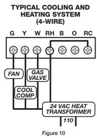
flowchart
graph TD
    A["FAN"] --> B["COOL COMP"]
    C["GAS VALVE"] --> B
    D["24 VAC HEAT TRANSFORMER"] --> B
    B --> E["RC"]
    style A fill:#f9f,stroke:#333
    style C fill:#f9f,stroke:#333
    style D fill:#f9f,stroke:#333
    style E fill:#ccf,stroke:#333
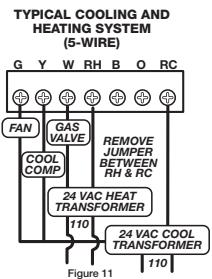
flowchart
graph TD
    A["COOL COMP"] --> B["FAN"]
    C["24 VAC HEAT TRANSFORMER"] --> D["GAS VALVE"]
    E["24 VAC COOL TRANSFORMER"] --> F["RESERVE JUMPER BETWEEN RH & RC"]
    B --> G["Figure 11"]
    D --> G
    F --> G
    style A fill:#f9f,stroke:#333
    style C fill:#f9f,stroke:#333
    style E fill:#f9f,stroke:#333
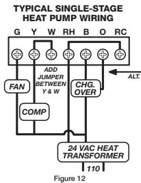
flowchart
graph TD
    A["FAN"] --> B["COMP"]
    C["CHG. OVER"] --> D["24 VAC HEAT TRANSFORMER"]
    E["ADD JUMPER BETWEEN Y & W"] --> B
    F["ALT."] --> D
    G["G"] --> A
    H["Y"] --> C
    I["W"] --> D
    J["RH"] --> C
    K["B"] --> D
    L["O"] --> D
    M["RC"] --> D
    N["110"] --> O["Figure 12"]
NOTE
If you have an electric system and the blower does not operate after installation, find the factory installed yellow wire currently attached to the "Y" terminal and move it to the "A" terminal on the sub-base.
☐ Place Base, Figure 3, over Sub-Base and attach by tightening three captive screws.
☐ Fasten loosely to wall using two mounting screws. Place a level against the bottom of the Base, adjust until it is level and then tighten mounting screws to secure.
☐ Find anticipator setting on old thermostat. Setting on new thermostat should be the same. Do this by carefully sliding the long pointer, Figure 2, over desired number printed on the anticipator. If old anticipator setting cannot be determined, look on gas control on furnace, or set at at .6. During heating season, furnace should operate about five times an hour. If adjustments are necessary, move heat anticipator pointer slightly and recheck. NOTE: Set pointer to 1.2 for millivolt systems.
□ Attach front cover, Figure 1, to base.
☐ Turn electricity and gas back on and set pointer on top of thermostat to desired temperature.
☐ FOR HEATING: Set slide switch to "Heat". Set fan switch to "Auto".
☐ FOR COOLING: Set slide switch to "Cool". Set fan switch to "Auto".
☐ FAN: For continuous blower operation, set switch to "ON". For automatic blower operation set fan switch to "Auto". Thermostat will then cycle the blower "on" and "off".
A thermostat can only control temperature near it. If you find that it is uncomfortable some distance away from the thermostat, change the setting in order to compensate for this.
FIGURE 3 SUB-BASE
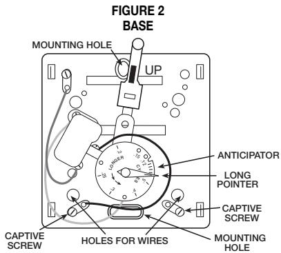
FIGURE 4 DECORATIVE WALL PLATE
natural_image
Simple geometric diagram with a square and rounded corners, no text or symbols present.TECHNICAL ASSISTANCE
If you have any problems installing or using this thermostat, please carefully and thoroughly review the instruction manual. If you require assistance, please contact our Technical Assistance Department at 856-234-8803 during regular business hours between 8:00AM and 4:30PM Eastern Standard Time, Monday through Friday. You can also receive technical assistance online anytime day or night at http://www.luxproducts.com. Our web site offers you answers to the most common technical questions, and also permits you to email your questions to our technical support staff at your convenience.
WARRANTY
Limited Warranty: If this unit fails because of defects in materials or workmanship within three years of date of original purchase, LUX Products Corporation will, at its option, repair or replace it. This warranty does not cover damage by accident, misuse, or failure to follow installation instructions. Implied warranties are limited in duration to three years from date of original purchase. Some states do not allow limitations on how long an implied warranty lasts, so the above limitation may not apply to you. Please return malfunctioning or defective units to the participating retailer from which purchase was made, along with proof of purchase. Please refer to "TECHNICAL ASSISTANCE" before returning thermostat. Purchaser assumes all risks and liability for incidental and consequential damage resulting from installation and use of this unit. Some states do not allow the exclusion of incidental or consequential damages, so the above exclusion may not apply to you. This warranty gives you specific legal rights and you may also have other rights which vary from state to state. Applicable in the U.S.A. only.
RECYCLING

This product does not contain mercury. However, this product may replace a unit which contains mercury and should not be disposed of in the trash. Contact your local waste management authority for proper disposal instructions for mercury in a sealed glass tube. If you have any questions, please call (856) 234-8803.
Marque : AEG-ELECTROLUX
Modèle : LUX T10-1143SA
Catégorie : Thermostat