HCL90X - Aspirateur BRANDT - Notice d'utilisation et mode d'emploi gratuit
Retrouvez gratuitement la notice de l'appareil HCL90X BRANDT au format PDF.

| Type de produit | Hotte aspirante |
| Marque | BRANDT |
| Modèle | HCL90X |
| Dimensions (L x P x H) | 90 cm x 50 cm x 15 cm |
| Poids | Environ 12 kg |
| Alimentation électrique | 220-240 V, 50 Hz |
| Classe d'isolation | Classe II (double isolation, sans mise à la terre) |
| Puissance moteur | 200 W |
| Nombre de vitesses | 3 |
| Éclairage | Ampoules (type standard) |
| Modes de fonctionnement | Évacuation (extraction) et recyclage (filtration) |
| Filtre à graisse | Métallique lavable (lave-vaisselle possible) |
| Filtre à charbon | Actif, à remplacer tous les 6 mois environ |
| Distance minimale entre la table de cuisson et la hotte | 65 cm |
| Installation | Murale ou sous meuble |
| Diamètre de sortie d'air | 150 mm |
| Niveau sonore | Environ 55 dB (à vitesse minimale) |
| Entretien | Nettoyage avec eau tiède et détergent neutre |
| Spécificités de sécurité | Déconnexion omnipolaire obligatoire sur l'installation fixe |
| Pièces détachées disponibles | Filtres à graisse, filtres à charbon, ampoules |
FOIRE AUX QUESTIONS - HCL90X BRANDT
Questions des utilisateurs sur HCL90X BRANDT
0 question sur cet appareil. Repondez a celles que vous connaissez ou posez la votre.
Poser une nouvelle question sur cet appareil
Téléchargez la notice de votre Aspirateur au format PDF gratuitement ! Retrouvez votre notice HCL90X - BRANDT et reprennez votre appareil électronique en main. Sur cette page sont publiés tous les documents nécessaires à l'utilisation de votre appareil HCL90X de la marque BRANDT.
MODE D'EMPLOI HCL90X BRANDT
English
WARNING
The distance between the hob and the lower part of the hood must be at least 65 cm.
The air collected must not be conveyed into a duct used to blow off smokes from appliances fed with an energy other than electricity (central heating systems, thermosphons, water-heaters, etc.).
Comply with the official instructions provided by the competent authorities in merit when installing the disposal duct. In addition, exhaust air should not be discharged into a wall cavity, unless the cavity is designed for that purpose.
The room must be well aerated in case a hood and some other heat equipment fed with an energy other than electricity (gas, oil, coal heaters, etc) operate at the same time. In fact the intake hood, disposing of air, could create a vacuum in the room. The vacuum should not exceed 0,04mbar. This prevents the gas exhausted by the heat source from being intaken again. It is therefore advisable to ensure the room contains air taps able to ensure a steady flow of fresh air.
This appliance has such technical particulars that it belongs to class II insulation, therefore it must not be earthed.
The following warning is valid in the United Kingdom only:
As the colours of the wires in the mains lead of this appliance may not correspond with the coloured markings identifying the terminals in your plug, proceed as follows: - the wire which is coloured blue must be connected to the terminal which is marked with the letter N or coloured black; - the wire which is coloured brown must be connected to the terminal which is marked with the letter L or coloured red; - neither wire is to be connected to the earth terminal of a three-pin plug.
When making the electrical connections, check that the voltage values correspond to those indicated on the data plate inside the
appliance itself.
In case your appliance is not furnished with a non separating flexible cable and has no plug, or has not got any other device ensuring omnipolar disconnection from the electricity main, with a contact opening distance of at least 3mm such separating device ensuring disconnection from the main must be included in the fixed installation.
Always switch off the electricity supply before carrying out any cleaning or servicing operations on the appliance.
USE
Avoid using materials which could cause spurts of flame (flambées) near the appliance.
When frying, take particular care to prevent oil and grease from catching fire. Already used oil is especially dangerous in this respect. Do not use uncovered electric grates.
To avoid possible risks of fire always comply with the indicated instructions when cleaning anti-grease filters and when removing grease deposits from the appliance.
MAINTENANCE
Thorough servicing guarantees correct and long-lasting operation.
Use lukewarm water and neutral detergent to clean painted appliances. Never use products containing abrasives. Take great care to prevent the use of corrosive or abrasive products when cleaning steel, copper or brass appliances. It is advisable to use specialized products according to the manufacturer's instructions.
DESCRIPTION
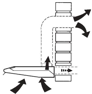
The appliance can be used both in Ducting version and Filtering version.
In the Ducting version (Fig. 1), cooking vapours and/or odours are conveyed straight outside (ceiling and/or wall) by a disposal duct, using the holes that are predisposed on the top and/or at the back of the apparatus.
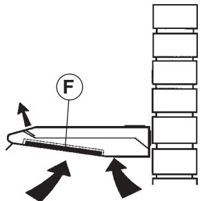
In the Filtering version (Fig. 2) cooking vapours and/or odours are depurated by a special activated
vegetal charcoal fiber panel and recirculated around the room by the front fissures. ATTENTION: For the filtering version it is absolutely necessary to use the special active vegetal charcoal fiber panel whereas for the ducting version it is not.
INSTALLATION
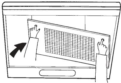
Before assembling the appliance it is necessary to take off the anti-grease grille. To take off the grill it is necessary to push this one towards the rear of the apparatus, by means of the proper knobs, so that it gets released, and to pull it downwards; to take it off completely, make it rotate on one side keeping the other one steady (Fig. 3).
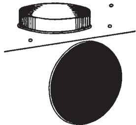
For the ducting installation of the appliance, connect one of the two discharge outlet to the external ducting and seal the other opening with the supplied cap (Fig. 4). For the filtering installation you must close both the discharge outlets of the apparatus using the supplied caps.
The following operations are essential for assembly: Install a proper wiring system.
If your apparatus is to be assembled as a Ducting appliance, you must first make the air venting hole and get a proper pipe to connect the hole to the flange of the hood.
Wall fitting
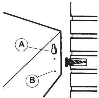
Making use of the appropriate drilling jig, apply the supplied blocks into the wall. Insert two of the supplied screws so that the apparatus can be hooked onto these ones by means of the holes provided on the appliance (Fig. 5A). Once the apparatus is hooked, fix it definitively to the wall using the two other screws and the holes made at its bottom (Fig. 5B). To avoid damage make exclusive use of the holes already prepared on the hood. Make the electrical connections.
Wall cupboard fitting
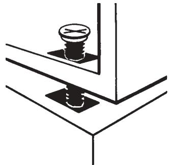
Using the appropriate drilling jig make the four fixing holes into the bottom of the wall cupboard and cut the air venting hole if the hood is a ducting version one (for the filtering version this hole is not necessary). Holding the hood against the bottom of the cupboard fix it to it by means of the supplied four screws (Fig. 6). Make the electrical connections.
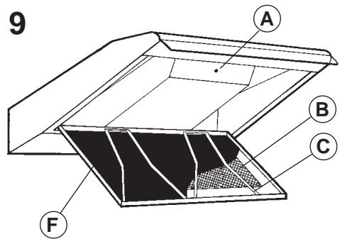
IMPORTANT:
Check the position of screw A (Fig. 9). For the ducting version screw A must be completely screwed; for the filtering version the screw must be completely unscrewed to let the sucked air to get out through the top fissures.
OPERATION
The hoods are provided with the following type of controls:
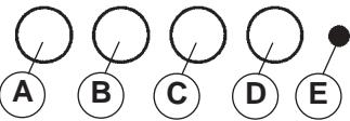
Controls of Fig. 7:
A = light switch.
B = first speed motor ON/OFF switch.
C = second speed switch.
D = third speed switch.
E = warning light: indicates motor operation.
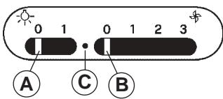
Controls of Fig. 8:
A = light switch.
Position 0: light off. Position 1: light on
B = motor switch.
Position 0: motor off. Position 1-2-3: motor first, second and thrid speed motor on.
C = warning light: indicates motor operation.
Filtering/ducting conversion:
The conversion can be done in the inside of the appliance. Access is possible by opening the grille as described beforehand. Verify that screw A (Fig.9) is completely unscrewed, so that the inside valve let the air to be conveyed again into the room through the slots. Insert the activated charcoal fiber panel (Fig.2F and 9F): lift the two stops made of metallic wire (Fig.9C); insert the fiber panel and set back the two stops.
In case the hood is a filtering version one, it is necessary to change the activated charcoal fiber panel (Fig.2F and 9F) according to utilization about every six month. To remove the fiber panel:
take off the anti-grease grill: by means of the proper knobs make the grill move towards the rear of the apparatus and drop the front part of it; now, keeping the right (or left) side of the grill steady, make the opposite side rotate so that it gets off the hood (Fig.3).
- lift the two metallic stops (Fig. 9C).
remove the fiber panel.
The anti-grease filtering panel is easily removed from the grille by opening it as described above and lifting the two stops made of metallic wire (Fig.9C). In the filtering version, to get access to the anti-grease panel the activated charcoal fiber panel must be removed too. Change the anti-grease panel according to use. If the panel is a metallic one it can be washed with some neutral detergent by hand or in a dish-washer.
To gain access to the light bulb(s), remove the anti-grease grill as described above and remove the bulb(s). Replace with lamps of the same type.
1
2
3
4
5
6
7
9
8

INSTRUCTIONS FOR USE HCL90