Excite IW5 - Høyttaler Crestron - Gratis bruksanvisning og manual
Finn enhetens veiledning gratis Excite IW5 Crestron i PDF-format.

Brukerspørsmål om Excite IW5 Crestron
0 spørsmål om dette apparatet. Svar på dem du kjenner, eller still ditt eget.
Still et nytt spørsmål om dette apparatet
Last ned instruksjonene for din Høyttaler i PDF-format gratis! Finn veiledningen din Excite IW5 - Crestron og ta den elektroniske enheten tilbake i hendene. På denne siden er alle dokumenter som er nødvendige for bruken av enheten din publisert. Excite IW5 av merket Crestron.
BRUKSANVISNING Excite IW5 Crestron
IW5, IW6, IW8
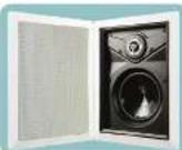
Excite™ In-Wall Speakers
Ideal components of every Sonnex™, Prodigy®, or Adagio® multiroom audio system, Excite™ speakers by Crestron® offer excellent sound quality and flexible installation in a range of popular sizes and configurations.
The IW5, IW6, and IW8 rectangular in-wall speakers, sold in pairs, include paint plugs installed on the front of the speakers, perforated metal grilles, and a mounting cut out template. The matte white ABS plastic frame and white metal grille can be painted to suit any room decor.

Installation
Determine Placement In Room
For applications such as classrooms, conference rooms, and multi-room audio distribution installation, the Excite in-wall speakers are available in three different sizes providing a great deal of flexibility to suit almost any application.
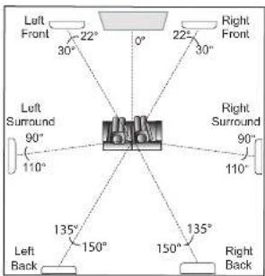
For home theater applications, the Excite in-wall speaker line is an excellent choice for the front, surround, and back channels.
As indicated in the figure below, suggested placement is at the angles from the 0^ primary viewing/ listening angle. For best results, place speakers anywhere from the listener's ear level to 2 to 3 feet (-0.6 to 0.9 meters) above.
Prepare Mounting Holes
Before finalizing the speaker locations, check to make sure there are no fixtures, pipes, air ducts, power cables or other wiring, or other possible obstructions. Use a good quality stud finder to locate wall framing.
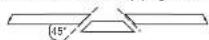
If you are not certain that there are no obstructions in the proposed speaker locations, carefully drill a small hole just through the wall near the middle of the location(s) and use one of the commercially available inspection devices designed for this purpose, or do one of the following:
- Use a piece of stiff wire, bent into an "L" shape, with one end long enough to explore an area equal to the size of the speaker with the toggle clamps extended. Insert the wire into the hole, make sure it moves freely through the proposed speaker area and that there is sufficient depth, or
- Use a drywall saw to cut a small hole at a 45° angle toward the inside of the hole. An angle cut simplifies repair since the removed piece can be reinserted to help plug the hole.
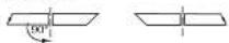
If there are no obstructions, use the supplied template to trace outlines of the mounting holes on the wall. Cut the final mounting holes at a 90° angle to the wall.
Paint the Speakers/Grilles
Speaker rim and/or grille painting should be done prior to mounting.
-
Leave the painting plug installed in the front of the speaker.
-
Carefully remove the material on the underside of the grille and set it aside for reinstallation. It may be necessary to use a knife or other sharp instrument to free an edge of the material so it can be peeled away. Use care to avoid cutting the material.
-
Dry brush or lightly spray the surface to be painted. Use care to avoid clogging the holes in the grille.
Install Cables
Run the cables from the audio source to each speaker location following all appropriate local codes. Strip the ends of the speaker cable wires 1/4" to 1/2" (6 mm to 12 mm) and twist the exposed strands.
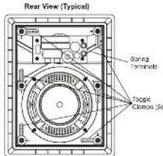
Mount/Remove Speakers
The in-wall speakers include six toggle clamps that simplify the mounting process. If grilles are mounted on the speakers, remove them before proceeding. (Refer to "Install" Remove Grilles", below.)
- Connect the speaker cable wires to the spring terminals by pressing the top of the terminals down and inserting the exposed strands into the hole. Make sure that left and right channels are connected to the left and right speakers, respectively, and that the + wires go to the + (red coded) terminals, and the - wires go to the - (black coded) terminals.
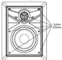
- With the toggle clamps turned inward, insert the speaker into the opening. As you tighten the six screws on the front of the speaker, the toggle clamps will first rotate into clamping position and then begin holding the speaker to the wall. Tighten the screws until the speaker is secure; do not overtighten.
- Speaker removal is accomplished by reversing the procedures given in steps 1 and 2 above.
a. Loosen the front screws to unclamp the speaker. Continue to loosen the screws until the toggle clamps rotate inward.
b. When the speaker is loose, carefully pull the speaker out from the opening.
c. Disconnect the wires from the terminals.
Install/Remove Grilles
To install the grille, place it in position and carefully press until the surface of the grille is flush with the surface of the outer flange.
To remove the grille, insert a slim, flat-blade screwdriver between the grille and the outer flange, and carefully pry the grille up and out.
It may be necessary to press one or more of the mounting screws and toggle clamps toward the front to push the grille free of the flange.
Front View (Typical)

For Regulatory Compliance information, refer to the latest version of Doc. 7148.
QUICKSTART DOC. 7128B (2029451) 05.11
www.crestron.com
888.273.7876201.767.3400
Spreads and concerns around the change without recall.

CRESTRON.
IW5, IW6, IW8
Excite™ In-Wall Speakers

Adjustments
Frequency Settings
Adjusting the high and low frequency range switch settings (refer to illustration below) is largely a matter of personal preference.
The settings produce the following results.
- Reduces the selected range 0. Lowiness remains neutral
+: Increases the selected range loudness
The recommended setting for the low frequency range (LF) switch is - to reduce bass when the speaker is in a corner, + to increase bass when the speaker is not near a wall or ceiling corner, and 0 (neutral) when the speaker is near one wall or ceiling corner
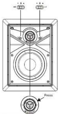
Aiming the Tweeter
The tweeter can be aimed toward the primary listening position by gently pressing on the plastic ring around the tweeter dome. (Refer to the illustration above.)

Specifications
IW5, IW6, IW8 Specifications
| SPECIFICATION | IW5 IW6 IW8 | |||
| WoolerSizeMaterial | 15.25 in (134 mm)Polypropylene | 16.50 in (185 mm)Polypropylene | 18.00 in (203 mm)Polypropylene | |
| TwixtorSizeMaterial | 10.79 in (20 mm)Treated cloth | 10.79 in (20 mm)Treated cloth | 10.98 in (25 mm)Treated cloth | |
| Surround Material | Rubber | Rubber | Rubber | |
| Minimum PerformanceFrequency Response (-3dB)Power Handling (Program)Sensitivity (1W @ 1m) | 60 Hz - 20 kHz60 W67 dB | 55 Hz - 20 kHz75 W69 dB | 60 Hz - 20 kHz125 W69 dB | |
| ElectricalBass SwitchTweater SwitchImpedance VoltageGrossover TypeTerminations | YesYesYes8 Ohm2nd Order L-RSpring Terminals | YesYesYes8 Ohm2nd Order L-RSpring Terminals | YesYes8 Ohm2nd Order L-RSpring Terminals | |
| MechanicalBaffle MaterialMounting SystemGrill MaterialSalvel TweeterPaint MaskSteel MaterialMaximum DepthAvalative Colors | ABSTaggle ClampsAluminumYesYes X2Steel3.93 in (100 mm)White | ABSTaggle ClampsAluminumYesYes X2Steel4.19 in (106 mm)White | ABSTaggle ClampsAluminumYesYes X2Steel4.42 in (112 mm)White | |
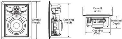
| DimensionsOverall HeightOverall WidthOpening HeightOpening WidthInstalled Depth | 10.98 in (279 mm)8.47 in (215 mm)9.60 in (246 mm)7.17 in (182 mm)3.62 in (92 mm) | 12.43 in (316 mm)9.54 in (242 mm)11.13 in (282 mm)8.24 in (242 mm)3.88 in (99 mm) | 14.47 in (268 mm)11.02 in (280 mm)13.17 in (335 mm)11.02 in (280 mm)4.11 in (105 mm) | |
| Weight | 3.4 lbs (1.5 kg) | 4.1 lbs (1.8 kg) 5.0 lb (2.3 kg) | ||
| EnvironmentalTemperatureHumidity | 41° to 104°F (5° to 40°C)10 to 90% RH (non-condensing, indoor use only) | |||
Front, Side, and Bottom Views (Typical)

Problem Solving
Troubleshooting
The following table provides corrective action for possible trouble situations. If further assistance is required, please contact a Crestron customer service representative.
| TROUBLE | POSSIBLE CAUSE(S) | CORRECTIVE ACTION |
| No sound or intermittent sound from speakers. | Cable connection error. | Verify cable connections between amplifier and speakers. |
| Amplifier not receiving input signal or amplifier malfunction. | Verify amplifier is functioning correctly, that it is receiving an input signal and that correct input source is selected. | |
| Constant noise such as buzz, hum. or hiss. | Faulty device in system. | Verify all devices in system are functioning properly. |
| System grounding fault. | Verify system grounding. | |
| Poor low frequency output. | Incorrect polarity connection at speaker. | Verify speaker connection polarity (i.e. + on speaker to - on amplifier). |
Further Inquiries
If you cannot locate specific information or have questions after reviewing this guide, please take advantage of Crestron's award winning customer service team by calling Crestron at 1-888-CRESTRON [1-888-273-7876]. For assistance in your region, please refer to the Crestron Web site (www.crestron.com) for a listing of Crestron worldwide offices.
You can also log onto the online help section of the Crestron Web site (www.crestron.com/onlinehelp) to ask questions about Crestron products. First-time users will need to establish a user account to fully benefit from all available features.
Future Updates
Check the Crestron website periodically for manual update availability and its relevance. Updates are identified as an "Addendum" in the Download column.
Crestron, the Crestron logo, Aragon, Escol, Pradigy and Sarnos new trademarks or registered trademarks of Crestron Electronics, Inc. in the United States and other countries. Other trademarks, registered trademarks, and trade names may be used in this document to refer to either the profiles drawing the marks and names at their products. Crestron's disclaimer proprietary interest in the marks and names of others.
©2011 Crestron Electronics, Inc.
For Regulatory Compliance information, refer to the latest
version of Doc. 7148.
QUICKSTART DOC. 7128B (2029451) 05.11
www.crestron.com
888.273.7876201.767.3400
Open and close around to change without return.

CRESTRON.