RB1290X6D - Batteri CyberPower - Gratis bruksanvisning og manual
Finn enhetens veiledning gratis RB1290X6D CyberPower i PDF-format.

Brukerspørsmål om RB1290X6D CyberPower
0 spørsmål om dette apparatet. Svar på dem du kjenner, eller still ditt eget.
Still et nytt spørsmål om dette apparatet
Last ned instruksjonene for din Batteri i PDF-format gratis! Finn veiledningen din RB1290X6D - CyberPower og ta den elektroniske enheten tilbake i hendene. På denne siden er alle dokumenter som er nødvendige for bruken av enheten din publisert. RB1290X6D av merket CyberPower.
BRUKSANVISNING RB1290X6D CyberPower
CyberPower®
Battery Replacement Instructions
All CyberPower Systems replacement battery cartridges listed in this manual use Non-Spillable Sealed Lead Acid Batteries. CyberPower Systems encourages environmentally sound methods for disposal and recycling of its battery cartridges. Please dispose of and/or recycle your batteries in accordance to the local regulations of your state.
K01-0003459-03
Replacement Battery Pack Table
| Model Name Battery QTY UPS or EEM Model | |
| SPINHOSK-100VDC | 3 |
| SPINHOSK-100VDC | 4 |
| SPINHOSK-100VDC | 5 |
| SPINHOSK-100VDC | 6 |
| SPINHOSK-100VDC | 7 |
| SPINHOSK-100VDC | 8 |
| SPINHOSK-100VDC | 9 |
| SPINHOSK-100VDC | 10 |
| SPINHOSK-100VDC | 11 |
| SPINHOSK-100VDC | 12 |
| SPINHOSK-100VDC | 13 |
| SPINHOSK-100VDC | 14 |
| SPINHOSK-100VDC | 15 |
| SPINHOSK-100VDC | 16 |
| SPINHOSK-100VDC | 17 |
| SPINHOSK-100VDC | 18 |
| SPINHOSK-100VDC | 19 |
| SPINHOSK-100VDC | 20 |
| SPINHOSK-100VDC | 21 |
| SPINHOSK-100VDC | 22 |
| SPINHOSK-100VDC | 23 |
| SPINHOSK-100VDC | 24 |
| SPINHOSK-100VDC | 25 |
| SPINHOSK-100VDC | 26 |
| SPINHOSK-100VDC | 27 |
| SPINHOSK-100VDC | 28 |
| SPINHOSK-100VDC | 29 |
| SPINHOSK-100VDC | 30 |
| SPINHOSK-100VDC | 31 |
| SPINHOSK-100VDC | 32 |
| SPINHOSK-100VDC | 33 |
| SPINHOSK-100VDC | 34 |
| SPINHOSK-100VDC | 35 |
| SPINHOSK-100VDC | 36 |
| SPINHOSK-100VDC | 37 |
| SPINHOSK-100VDC | 38 |
| SPINHOSK-100VDC | 39 |
| SPINHOSK-100VDC | 40 |
| SPINHOSK-100VDC | 41 |
| SPINHOSK-100VDC | 42 |
| SPINHOSK-100VDC | 43 |
| SPINHOSK-100VDC | 44 |
| SPINHOSK-100VDC | 45 |
| SPINHOSK-100VDC | 46 |
| SPINHOSK-100VDC | 47 |
| SPINHOSK-100VDC | 48 |
| SPINHOSK-100VDC | 49 |
| SPINHOSK-100VDC | 50 |
| SPINHOSK-100VDC | 51 |
| SPINHOSK-100VDC | 52 |
| SPINHOSK-100VDC | 53 |
| SPINHOSK-100VDC | 54 |
| SPINHOSK-100VDC | 55 |
| SPINHOSK-100VDC | 56 |
| SPINHOSK-100VDC | 57 |
| SPINHOSK-100VDC | 58 |
| SPINHOSK-100VDC | 59 |
| SPINHOSK-100VDC | 60 |
| SPINHOSK-100VDC | 61 |
| SPINHOSK-100VDC | 62 |
| SPINHOSK-100VDC | 63 |
| SPINHOSK-100VDC | 64 |
| SPINHOSK-100VDC | 65 |
| SPINHOSK-100VDC | 66 |
| SPINHOSK-100VDC | 67 |
| SPINHOSK-100VDC | 68 |
| SPINHOSK-100VDC | 69 |
| SPINHOSK-100VDC | 70 |
| SPINHOSK-100VDC | 71 |
| SPINHOSK-100VDC | 72 |
| SPINHOSK-100VDC | 73 |
| SPINHOSK-100VDC | 74 |
| SPINHOSK-100VDC | 75 |
| SPINHOSK-100VDC | 76 |
| SPINHOSK-100VDC | 77 |
| SPINHOSK-100VDC | 78 |
| SPINHOSK-100VDC | 79 |
| SPINHOSK-100VDC | 80 |
| SPINHOSK-100VDC | 81 |
| SPINHOSK-100VDC | 82 |
| SPINHOSK-100VDC | 83 |
| SPINHOSK-100VDC | 84 |
| SPINHOSK-100VDC | 85 |
| SPINHOSK-100VDC | 86 |
| SPINHOSK-100VDC | 87 |
| SPINHOSK-100VDC | 88 |
| SPINHOSK-100VDC | 89 |
| SPINHOSK-100VDC | 90 |
| SPINHOSK-100VDC | 91 |
| SPINHOSK-100VDC | 92 |
| SPINHOSK-100VDC | 93 |
| SPINHOSK-100VDC | 94 |
| SPINHOSK-100VDC | 95 |
| SPINHOSK-100VDC | 96 |
| SPINHOSK-100VDC | 97 |
| SPINHOSK-100VDC | 98 |
| SPINHOSK-100VDC | 99 |
| SPINHOSK-100VDC | 100 |
CyberPower
CyberPower Systems, Inc. www.cyberpower.com
Please visit our website for local contact information.
Please visit our website for local contact information.
MODEL: OL1000RTXL2U, OL1500RTXL2U, OL2200RTXL2U.
OL3000RTXL2U, OL3000RTXL2UHV, OL1000ERTXL2U, OL1500ERTXL2U, OL2000ERTXL2U, OL3000ERTXL2U, OL1000RT JP, OL1500RT JP, OL2200RT JP, OL3000RT JP
-
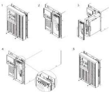
Remove the front panel.
-
Remove the screws securing the battery retention panel
-
Pull the battery pack out together with the retention panel slowly
and then put the new battery pack back into the UPS.
- Reconnect the battery pack connectors to the UPS. Then lighten
the screws of the battery retention panel
- Reinstall the front panel.
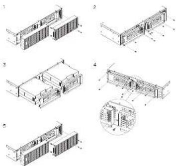
Smart App Online EBM for RT 1-1.5KVA SeriesSmart
MODEL: BP36V60ART2U, BPE36V60ART2U, BPE36V60ART2US
-
Remove the front panel.
-
Remove the screws securing the battery retention panels.
-
Pull the battery packs out together with the retention panels
slowly and then put the new battery packs back into the EBM.
- Reconnect the battery pack connectors to the EBM enclosure.
Then tighten the screws of the battery retention panel.
S. Reinstall the front panel
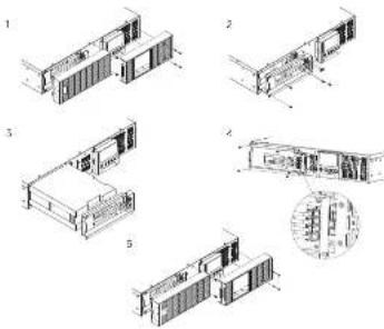
Smart App Online RT 6-10KVA SeriesSmart App
MODEL: BP72V60ART2U, BPE72V60ART2U, BPE72V60ART2US
-
Remove the front panel.
-
Remove the screws securing the battery retention panels. Unscrew the battery connector retention hardware. Disconnect the battery power cables and then remove the panel itself.
-
Pull the battery packs out slowly and then put the new battery packs back into the compartment.
-
Reconnect the battery pack to the ESM enclosure and screw on the battery connector retention hardware. Tighten the screws of the battery retaining cover.
WARNING - It is very important to reconnect battery connections with the correct polarity. Connectors are color coded red and black for positive and negative polarity respectively. Permanent damage may be caused to the equipment if polarity is reversed.
- Rainfall the front panel.
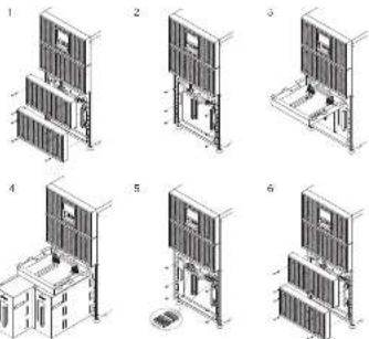
MODEL: BP240VL3U01, BP240VL3U02, BP240V3OART3U, BP240V5OART3U, BPE240V3OART3U, BPE240V5OART3U, BPE240V3OART3US, BPE240V5OART3US
-
Remove the front panel.
-
Remove the screws securing the battery retention panel.
-
Raise the battery retention panel above the battery compartment opening to allow the battery trays to be pulled out. Then put the new battery trays into the compartment.
-
Align and reconnect the battery connectors and tighten the screws of the battery retention panel.
-
Reinstall the front panel.
e EBM for 3KVA Online Tower 1-3KVA Series
MODEL: OL1000XL, OL1500XL, OL2200XL, OL3000XL, OL1000EXL, OL1500EXL, OL2000EXL, OL3000EXL, OL1000XL JP, OL1500XL JP, OL2200XL JP, OL3000XL JP
-
Remove the front panel.
-
Remove the screws securing the battery retention panel
-
Pull the battery pack out together with the retention panel slowly and then put the new battery pack back into the UPS.
-
Reconnect the battery pack connectors to the UPS. Then tighten the screws of the battery retention panel.
-
Reinstall the front panel.
Smart App Online Tower 6-10KVA Series
MODEL: OL6000, OL8000, OL10000, OL8000E, OL8000E, OL10000E
-
Remove the front panel.
-
Remove the screws securing the battery retention panel.
-
Raise the battery retention panel above the battery compartment opening to allow the battery trays to be pulled out.
-
Put the battery trays out slowly and then put the new battery trays back into the compartment.
-
Reconnect the battery connectors and tighten the screws of battery retention panel.
-
Reinstall the front panel
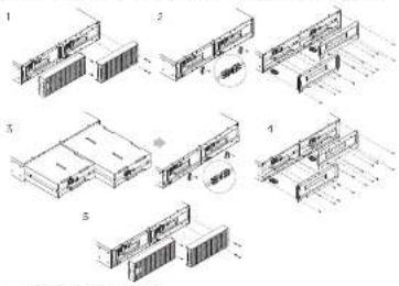
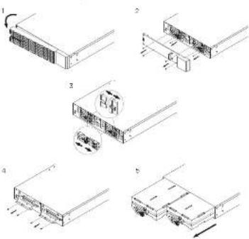
Smart App Online RT 5-6KHD Series
MODEL: OLSKRTHD, OLSKRTHD, OLSKERTHD, OLSKERTHD
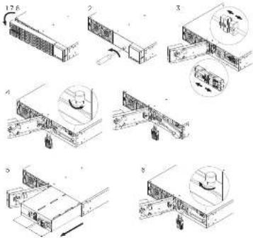
- Remove the front panel.
- Unscrew and open the battery access door. This screw is designed to be fixed on the door, do not remove it from the metal cover.
- Disconnect the internal battery connector and battery management module connector.
- Unscrew the thumbscrew on the battery retention bracket and then remove it.
- Assemble the battery retention
bracket and tighten the thumbscrew - Connect the internal battery connector and battery management module connector. Ensure that they are seated properly (connector will click into place).
- Tighten the screw on the battery access door and install the front panel.
- Execute a battery test via the LCD control panel. To do this go to the Main Menu and select the Diagnostics Icon, then select Battery Test and Activate. After the Battery Test, go back to the Main Menu and select the Set UP icon, then select Battery Install Date to set the battery installation date. This operation can also be done via PowerPanel® Business Edition Agent or the RMCARD web Interface. Please see their respective User Manuals for detailed instructions.
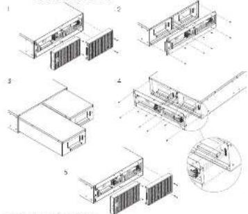
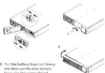
Smart App Online EBM for RT 5-6KHD Series
MODEL: BP144VL2U01, BPE144VL2U01
- Remove the front panel.
- Unscrew and open the battery access door. Loosen the two screws on the battery connectors.
- Disconnect the battery and battery management module connector.
- Unscrew the battery retention bracket and then open it.
- Full the battery trays out slowly and then put the new battery trays into the compartment
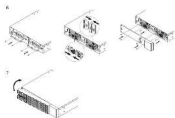
natural_image
Technical line drawings of server racks and equipment components (no text or symbols)- Assemble battery retention cover and the battery connectors Tighten the battery access door.
- Install the front panels. Execute a battery test via the LCD control panel. To do this go to the Main Menu and select the Diagnostics Icon, then select Battery Test and Activate. After the Battery Test, go back to the Main Menu and select the Set UP icon, then select Battery Install Date to set the battery installation date. This operation can also be done via PowerPanel® Business Edition Agent or the RMCARD web interface. Please see their respective User Manuals for detailed instructions.