CCH50H4C - Airconditioner Maxicool - Gratis gebruiksaanwijzing en handleiding
Vind de handleiding van het apparaat gratis CCH50H4C Maxicool in PDF-formaat.


| Type product | Mobiele airconditioner |
| Merk | Maxicool |
| Model | CCH50H4C |
| Koelcapaciteit | 12.000 BTU/h (3,5 kW) |
| Afmetingen (BxHxD) | 45 x 70 x 30 cm |
| Gewicht | 35 kg |
| Voeding | 220-240 V ~ 50 Hz |
| Vermogen | 1500 W |
| Energielabel | A+ |
| Functies | Koelen, ontvochtigen, ventileren, turbo, slaapmodus |
| Ontvochtiging | 1,5 l/u |
| Geluidsniveau | 65 dB (A) |
| Luchtdebiet | 350 m³/u |
| Vulmiddel | R32 |
| Afvoerslangen | Luchtslang (150 cm) en waterslang (100 cm) |
| Filters | Wasbare stoffilter |
| Onderhoud en reiniging | Filter elke 2 weken reinigen; condensor jaarlijks schoonmaken |
| Veiligheid | Oververhittingsbeveiliging, automatische uitschakeling, kinderslot |
| Verbruik | 1,2 kWh/uur (gemiddeld) |
| Reserveonderdelen | Afstandsbediening, filter, afvoerslangen |
| Reparatie-index | 8,2/10 (onderhoudsvriendelijk) |
Veelgestelde vragen - CCH50H4C Maxicool
Gebruikersvragen over CCH50H4C Maxicool
0 vraag over dit apparaat. Beantwoord die u kent of stel uw eigen vraag.
Stel een nieuwe vraag over dit apparaat
Download de handleiding voor uw Airconditioner in PDF-formaat gratis! Vind uw handleiding CCH50H4C - Maxicool en neem uw elektronisch apparaat weer in handen. Op deze pagina staan alle documenten die nodig zijn voor het gebruik van uw apparaat. CCH50H4C van het merk Maxicool.
GEBRUIKSAANWIJZING CCH50H4C Maxicool
Thank you for choosing MaxiCool products!
Air conditioning facilities are valuable products. In order to protect your legitimate rights and interests, please make sure that the installations are made by professional technicians. This Manual is a general purpose version for the ceiling-mounted air conditioning systems manufactured by MaxiCool. The one that you have chosen might be a little different in appearance from the ones described in this Manual. But these differences will not have any impacts upon your operation and use of the system.
Please read the Manual carefully before you operate the system and check to see if the model is identical to the one you have purchased. Keep this Manual properly in case you might refer to it in the future.
CONTENTS
| Instructions to End-Users | 1 |
| Nomenclature and Functions | 2 |
| Use of Remote Controller | 3 |
| How to Get the Achieve Optimized Performances | 6 |
| Method of Maintenance and servicing | 7 |
| Phenomena Diagnosis and Treatment | 9 |
| Selection of Installation Position | 10 |
| Installation of Indoor Unit | 13 |
| Installation of Outdoor Unit | 16 |
| Installation of Refrigerant Pipe and Drainage Tube | 17 |
| Installation of Electric Components | 21 |
| Installation of Decoration Panel | 24 |
| Test Running | 29 |
INSTRUCTIONS TO END-USERS
Prior to the use of the air conditioning system, please read the Instructions to Users carefully so as to ensure normal performance of the units.
Do not open the air-return grids of the indoor unit during the operation. | Do not place objects at the air inlet or outlet; do not insert sticks or other hard objects into the opening of the units. | Do not place insecticides, paints or other inflammable spray agents near the air outlet; do not spray such things against the air conditioner. |
Operate the machine only under the nominated voltage and frequency and with corresponding protective devices. Never use copper wires to substitute the fuses, which might lead to operational faults or fire hazards. Never use copper wires to substitute the fuses, which might lead to operational faults or fire hazards. | The grounding terminal of the units must be well connected to the grounding of the power source.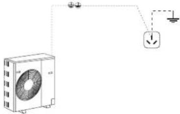 | When doing the cleaning of the machine, do not splash water to the units.It might result in faulty operations or electric shocks and other hazards.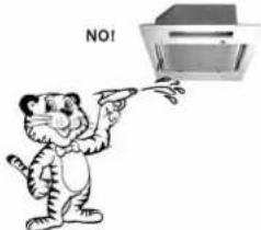 |
Do not block the air inlet and outlet of the indoor or outdoor units so as to avoid possible negative impacts upon the machine performances or hazards.Indoor unitAir delivery blocked Outdoor unitAiobl Outdoor unitAiobl | Do not exposes your body to the cooled air from the unit, which might cause discomfort or harm your health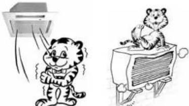 Do not sit on the outdoor unit or place objects on top of it. If the machine falls down or the objects fall down from the machine, it might cause human injuries or other hazards. Do not sit on the outdoor unit or place objects on top of it. If the machine falls down or the objects fall down from the machine, it might cause human injuries or other hazards. | Non-operation for long timeIf the machine is not in use for long time, the power source should be disconnected for the sake of safety and energy-saving.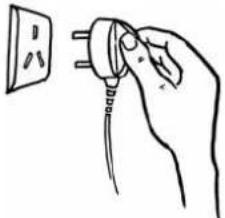 |
In the case that the breaker is frequently disconnected, you should stop the operation of the machine and contact the dealer or our company authorized maintenance shop. | When you restart the operation after a long period of non-operation, you should carefully check if the air conditioner and electric wire connections are in proper state.  |
NAMES OF PARTS AND THEIR FUNCTION
Indoor unit

Outdoor unit
A Air outlet B Air inlet


natural_image
Technical line drawing of a mechanical device with fan and labeled components (A, B), no readable text or symbols beyond labels
Operation control panel on the front pane

flowchart
graph TD
    A["Receiver of remote control signal"] --> B["Power lamp indicator"]
    B --> C["Run lamp indicator"]
    C --> D["POWER"]
    C --> E["RUN"]
    C --> F["TIMER"]
    C --> G["PROTECT"]
    H["Emergency operation key"] --> I["This button can be used as emergency operation, when remote controller is not available."]
    J["Timer lamp indicator"] --> K["The lamp lights when the unit fails."]
USE OF REMOTE CONTROLLER
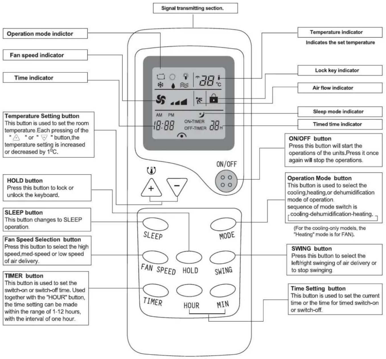
NOTE:
- Above figure shows all indications for the purpose or explanation, but practically only the pretinent.
Operating Machine In selected modes
- Point the remote controller at the unit, press the "MODE" button, select the needed mode cooling, heating (ventilating for cooling-only models) and dry.
- Press the temperature setting button to increase or decrease the readings until the needed temperature is displayed;
- In cooling/heating operations, the temperature difference of 5^ between the selected temperature and the ambient temperature is most suitable for your health.
- Press the air volume selection button to choose the air volume you want;
- Press the air direction button or swinging air selection button to choose the left/right air direction you want.
PRESENT TIME SETTING PROCEDURE
When cells are inserted, the present is automatically set to AM 12:00. Ex: set to AM 10:30.
-
Unload the back cover push the lock button with the tip of a ball pen, etc. The time indicator is flickering and can set the present time.
-
Press the Hour button. (Set to AM 10:)
-
Press the MIN button. (set to 30)
-
Press the CLK button again, then reattach the back cover.
NOTE: The timer is set on the basis of the present time. So set the present time correctly.

SLEEP OPERATION PROCEDURE
Use this mode to reduce operation sound when sleeping, etc.
Press the SLEEP button, the air flow sound from the indoor unit is decreased.
Press the SLEEP button again can release the mode.
and the air conditioner will be stopped automatically in 8 hours.
NOTE:
- Use the sleep mode when you are going to bed. If this mode is used in the day, the capacity is reduced since the ambient temperature is too high. (COOL MODE).
- During the operation of cooling, the room temperature will be raised by 1^ higher than the setting after the machine begins to operate in the sleeping mode.
- During the operation of heating mode, the room temperature will be dropped 2^ lower than the setting after the machine begins to operate in the sleeping mode.
TIMER OPERATION PROEDURE
Timed switch-off
- During the operation of the air conditioner, press the TIMER button and the air conditioner will enter the timed switch-off mode.
- Press the HOUR button to set the needed time. Every the button is pressed, indication change is the following sequence.
- After the setting, the digits shown on the display screen will go down by 1 for every elapsed hour.
$$ 1 \rightarrow 2 \rightarrow \dots \dots \rightarrow 1 2 \rightarrow 1 $$
USE OF REMOTE CONTROLLER
Timed switch-on
- When the air conditioner is in the standby mode, press the TIMER button and the air conditioner will enter the timed switch-on mode.
- Press the HOUR button to set the needed time, The timer can make the setting in the range from 1-12 hours.
- After the setting.the digits shown on the display screen will go down by 1 for evey elapsed hour.
Releasing procedure
Press the TIMER button again to release the mode.
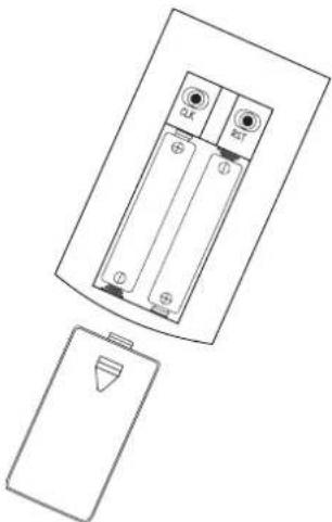
REPLACEMENT OF BATTERIES
- When the signal from the remote controller become weak and the indoor unit can not receive it properly; or the indications on the display screen becomes blurred, please replace with two new batteries.
● The positive and negative poles must match the installation positions.
● The positive and negative poles must match the installation positions.
● New batteries of the same type have to be used for replacement. - If the remote controller is not to be used for long time, take out the batteries so as to prevent the leakage of the electrolyte from damaging the controller.
natural_image
Technical line drawing of a battery pack with two terminals and a separate battery casing (no text or symbols)NOTE:
- Do not use an old battery with together with a new one.
- The life of cell made in conformity to JIS or IEC is 6 to 12 moths in normal use, If it is used longer or an unspecified cell is used, a liquid leaks from the cell, causing the remote controller imperative.
- Guideline of the life time is printed on the battery. The battery life may be shorter than of air conditioner depending on the date of manufacture, However, the battery may be alive ever after the nominal life time expired.
HOW TO GET THE OPTIMIZED PERFORMANCES
Clean the air filter screen from time to time
Blocking of the air filter screen will reduce the airflow volume and affect the cooling or heating effects. If the air filter screen is too dirty, it might lead to faulty operation of the air conditioner. Please clean the air filter screen at least once every two weeks.
If the air conditioner has not been in use for a long time, please clean the air filter screen before you put it into operation.
Cleaning steps:
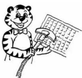
- Remove the air filter screen;
- Use a vacuum cleaner to clean it or use clean water to flush it.
- After the screen is flushed clean with water, place it in a cool and dry place until it is dried. Do not heat it dry with fire.
natural_image
Cartoon illustration of a tiger holding a computer with a grid screen (no text or symbols)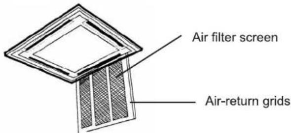
Set the room temperature at a comfortable setting.
During cooling operation, the temperature difference of 5^ C between the room temperature and the outdoor ambient temperature is most comfortable. Excessively low setting of room temperature might do harm to your health and consume lots of power energy. During the cooling operation, raising the room temperature by 1^ C will save about 10 % of power consumption for you.

Try to avoid the heat sources as much as you can.
When the units are in the cooling mode, you should pull the window curtains to shed off the direct exposure of sunlight. The doors and windows of the room must be closed, and frequent opening of the door should be avoided.

Keep the room air exchanged from time to time.
Open the windows of the room periodically to let the fresh air in, which makes the room air more comfortable and healthy.

natural_image
Simple line drawing of a hand holding a curved object with a diamond-shaped inset (no text or symbols)When cleaning or maintenance to the machine, the power must be turned off. Only a qualified service person is allowed to perform maintenance and service.
- Clean the indoor units
Method 1: Use a piece of clean, soft and dry cloth to wipe the exterior of the unit;
Method 2: Use neutral household detergent solution (such as the one for laundry purpose) to clean the grease, oily filth or fingerprint stains.

natural_image
Cartoon tiger watering a window with a bucket (no text or symbols)The procedure of opening the suction grille and removing the air filter
- Open the suction grille: Pull it downward slowly while pressing the buttons provided on two spots, (Do the same procedure for closing.) shown as fig.1
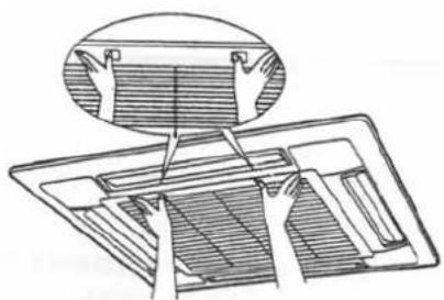
natural_image
Technical line drawing of a mechanical component with an inset showing a cross-section (no text or symbols)fig 1
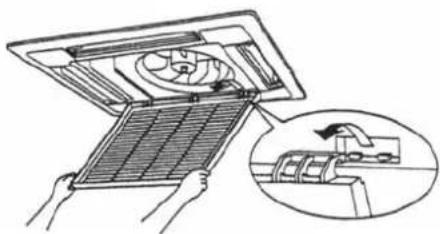
- Remove the air filter, Pull the hook of the air filter out diagonally downward, and remove the filter, shown as fig .2

natural_image
Diagram of a device with a fan inside a rack, showing hand movement and a magnified inset (no text or symbols)fig 2
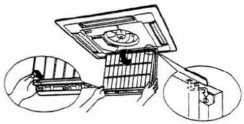
- Take out the suction grille: Open the suction grille 45 degrees and lift it upward, shown as fig .3
natural_image
Illustration of a mechanical device with a fan inside, showing hands holding a grid and an inset view of a pipe assembly (no text or symbols)fig 3
METHOD OF MAINTENANCE AND SERVICING
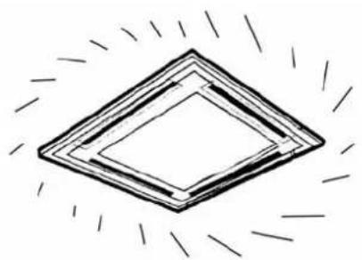
- After cleaning, install the air filter and suction grille, shown as fig.4
natural_image
Illustration of a hand assembling a mechanical device with a magnified inset showing the process (no text or symbols present)fig 4
When the operational season is over and the air conditioner is not to be used for a long period of time.
● Turn on the machine and set the air ventilation mode to run the machine for 3-4 hours so that the interiors of the units are completely dried.
● Turn off the machine and disconnect the power source.
● Thoroughly clean the air filter screen and the outdoor unit.
Take out the batteries of the remote controller and put the remote controller in a proper place.
● Cover the outdoor unit with a protective cover to prevent dust from entering the unit.
natural_image
Simple line drawing of a diamond shape with radiating lines around it (no text or symbols)Inspections during operational seasons
- Check to see if the outdoor unit is properly installed, the grounding wire is properly connected, and the appearance of the power cable is in proper state;
- Check to see if the air inlet and outlet for the indoor unit and outdoor unit is blocked;
- Check to see if the air filter screen is properly installed.

natural_image
Line drawing of a mechanical or electrical enclosure with a fan-like grille and a rectangular housing (no text or symbols)PHENOMENA ANALYSIS AND TREATMENT
Analysis on faulty performances
Please read the following contents before contacting the maintenance people when the air conditioner is not working properly and you suspect some machine faults:
| TROUBLE | PHENOMENA | CAUSES | TREATMENT |
| Air conditioner does not work. | Press the On/Off button but the indoor unit does not utter a "bee.." sound and the indication light is not on. | Power failure | Press the On/Off button again after the power is resumed; |
| Power not connected; | Connect the power source; | ||
| Fuse blown; | Replace the fuse; | ||
| Breaker disconnected; | Connect the breaker; | ||
| Remote controller is operated beyond the range of reception; | Bring the remote controller into the range of reception by the indoor unit; | ||
| Batteries in the remote controller exhausted (screen display dimmer) | Replace with new batteries. | ||
| Air conditioner not to be activated; | Remote controller indicates that the machine is working. | The air conditioner is activating its restart protective circuit. 3 minutes are needed before the restart of the machine; | Please wait for 3 minutes as the restart protective circuit is working; |
| Air inlet or outlet of the indoor or outdoor unit blocked; | Remove the blocking stuff; | ||
| Air conditioner activated but soon stopped | Air filter screen blocked by dust or mud. | Clean the air filter screen. | |
| There is air delivery at the outlet, but it is not cooling or heating | Control panel indications normal | Room temperature not properly adjusted | Reduce or increase the room temperature setting. |
| Dust blocking the air filter screen | Clean the air filter screen. | ||
| Blocking objects at the inlet or outlet of the indoor or outdoor units | Remove the objects. | ||
| Door or windows open | Close the door or windows. |
Once the machine stops operation due to power failure, it will not be reactivated even when the power is resumed. You have to start the operation by pressing the On/Off button on the remote controller once again.
Self diagnosis function
Our company provides the end-users with thoughtful services by installing various diagnostic systems to indicate the following irregular performances.
The following phenomena are not faulty operational performances:
● Sometimes the air sent out from the air conditioner may smell some odd odors. This is due to the cigarette smoke, the cosmetic smell, the odors of walls or furniture pieces in the room that are stained on the air conditioner.
| Flashing of red lights | Performance faults |
| 1 time/1 seconds | Faulty coils |
| 1 time/3 seconds | Cold air protection(normal function) |
| 2 times/4 seconds | Room temperature sensor faults |
| 3 times/5 seconds | Faulty coils |
| 4 times/6 second | Outdoor unit (overflow, electric network voltage faults) |
| 5 times/7 seconds | Frost resistance protection(normal function) |
| 7 times/9 seconds | Abormity of out feed back |
| 8 times/10 seconds | Overheating protection |
| 9 times/11 seconds | Water pump faults |
- During the operation or when the machine is stopped, some "ZZZ..." sound may be heard. This is because the refrigerant inside the air conditioner is still flowing.
- When the cooling or heating operation is started or stopped, some "patting" sound may be heard. This is because some parts of the surface boards are expanded due to changes of temperature, which results in the friction of these parts. This is not a performance fault.
SELECTION OF INSTALLATION POSITION
WARNING: Please request your dealer to carry out removal and reinstallation if necessary, important installation could cause water leakage, electric shocks or fire.
Selection of installation for the indoor unit
● To install the indoor unit on the rooftop or frame that can support the load of the unit;
● To be installed at the position where the air delivered from the unit can reach every corner of the room;
● To avoid being affected by the outdoor air;
● To avoid blockage to the air inlet or outlet of the unit;
● To avoid possible generation of steam, oil smoke or flammable gases;
● To avoid high-frequency facilities (such as high frequency arc welders, etc.);
- Not to install a fire alarming device near the air outlet of the unit (during operation, the fire alarm device might be erroneously triggered by the warm air from the unit);
● To avoid the places where acid solutions or sulfate substances or other special spraying agents are frequently used;
● To leave sufficient spaces for maintenance.
Selection of installation position for outdoor unit (consult the end-user)
● To avoid direct exposure to the sunlight;
● To avoid strong wind;
● To avoid inflammable gases
● To facilitate connections of supplementary pipes for the power source and connection to the indoor unit;
● To avoid causing disturbance or trouble to your neighbors;
● To avoid installing on the supporting frame with possible louder noise and vibration;
● To fix the supporting feet firmly if the unit is to be installed at a position high above the ground;
● During operation, some condensing water may be exhausted from the base plate of the unit;
● To match the following requirements for the height differences between the indoor and outdoor unit, the length of the refrigerant pipe and the numbers of pipe bending:

flowchart
graph TD
    A["Indoor Unit"] -->|A| B["Outdoor Unit"]
    B -->|B| A
    B -->|C| A
| Model | Pipe length of A (one way) | Height difference B (one way) | Numbers of pipe bending C |
| 2500W.3500W | 10m max. | 5m max. | 10 max. |
| 5100W.7000W | 15m max. | 6m max. | 10 max. |
| 7500W.8800W | 20m max. | 10m max. | 10 max. |
| 11000W | 20m max. | 10m max. | 10 max. |
Note: Either the indoor unit or the outdoor unit can be higher, but the height difference must comply the above-stated requirements.
Installation and maintenance spaces for the outdoor unit
When a single unit is installed:
(unit: mm)
(1) When there are blocking objects above
In the case that the spaces are left as shown in the figure, it does not matter much whether there are blocking objects in the rear.
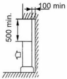
(2) When the front (air outlet) is open
In the case that the spaces are left as shown in the figure, it does not matter much whether there are blocking objects on three sides of the unit (with the top left open).

(3) When there are blocking objects only in front
In this case, the rear and the two flanks as well as the top should be left open.

(4) When there are blocking objects in the front and rear
Do not use the following space specifications. Please refer to Item (5)
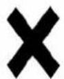

Make sure of the maintenance space in the front as shown below.

(5) When there are blocking objects only in the front and rear
In the places where there are blocking objects and air flow is poor, the height and width of the blocking object must be within the following specification in order to prevent from the risk of short circuits for the outdoor unit air inlet and outlet (If the front and rear can meet this condition, there will be no particular limitations for the two flank sides).
Width of blocking objects: No larger than 1.5 times of the width of the outdoor unit
Height of blocking objects: No larger than 1 time of the height of the outdoor unit

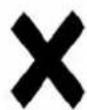
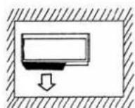
(6) When there are blocking objects all round the unit
Although the top is left open, the installation still cannot be done in this case.
When more than one unit is to be installed: (unit: mm)
(1) When the units are installed in parallel (please remove the screws on the side of the supplementary piping cover)

Note: The topside must be open for such kind of installation.


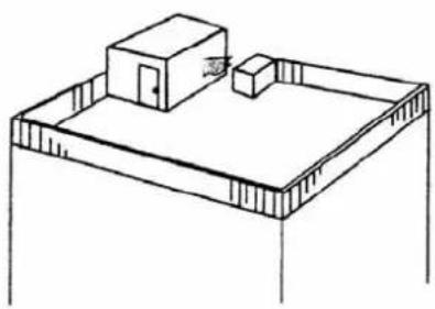
When the installation is made on the rooftop or other places subject to strong wind:
When the outdoor unit is to be installed on the rooftop or at the places where there are no other buildings around, it is required to avoid the strong wind from blowing directly into the air outlet of the outdoor unit so as to prevent the negative impacts on cooling or heating performances due to insufficient airflow of the outdoor unit heat exchanger and to prevent from faulty performances.
When there are walls in the vicinity, the air outlet should face the wall and keep a space of 500mm from the wall.
When the air outlet is affected by the strong wind, the installation position should be changed so as to make the air outlet at a straight angle from the wind direction.
natural_image
Isometric line drawing of a two-story building with a small structure on top, no text or symbols present
BEFORE INSTALLATION
- Do not throw away the attached parts needed for installation until the work is finished.
- Decide the route to carry the unit to installation site.
- Do not unpack until the unit is carried to the installation site.
SELECTING INSTALLATION SITE
- When the ceiling temperature is above 30^ and humidity more than RH80% , please attach the insulated materials to the unit. Please use the thickness of glass wool polyethylene foam more than 10mm . (when the thickness is more than 10mm , please put it at the opening).
Caution: keep indoor and outdoor unit power supply wiring and transmission wiring at least 1 meter away from televisions radios, This is to prevent image interference and nosie in those electric appliance. (Nosie may be granted depending on the conditions under which the electric wave is generated ever if 1 meter is kept.
Height of ceiling
- This production can be installed at the height from 2.5m to 3.5m. But when the height of ceiling is higher than 2.7m, it is essential to field set by the remote controller.
- Use suspension bolts for installation, Check whether the ceiling is strong enough to support the weigh of the unit or not. If there is a risk, reinforce the ceiling before installing the unit. (Installation pitch is marked on the paper pattern for installation. Refer to it to check for requiring reinforcing.)
Space required for installation

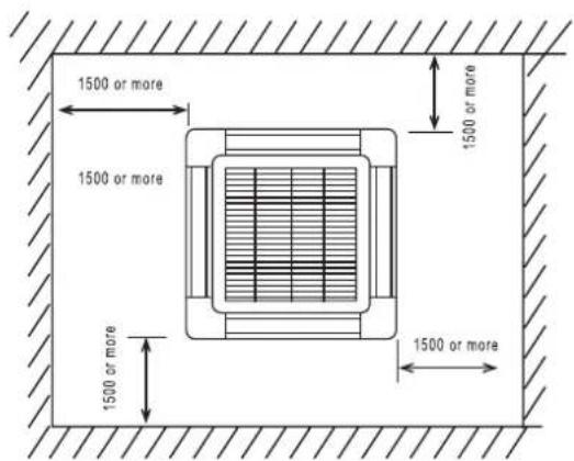
| MODEL | H |
| 2500W.3500W.5100W | 240 |
| 7000W.7500W.8800W.11000W | 298 |
INSTALLATION OF INDOOR UNIT
Relation of ceiling opening to unit and suspension bolt position
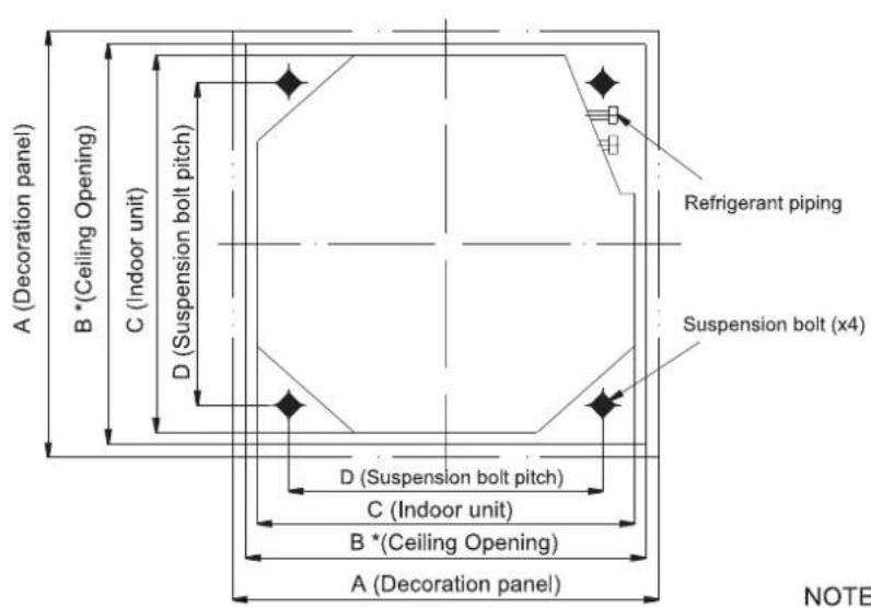
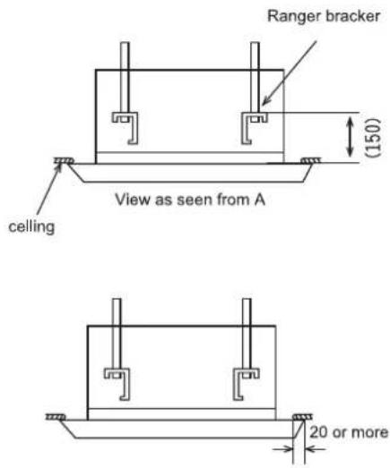
NOTE: The ceiling opening dimension with mark* is accotable up to 910mm.however,a ceiling-panel overlapping should be kept 20mm or more.
unit:mm
| model | Qimmension | ||||
| A | B | C | D | E | |
| 2000W.3500W.5000W.5100W | 650 | 610 | 580 | 400 | 600 |
| 7000W.7500W.8800W.11000W | 950 | 890* | 840 | 680 | 780 |
Make the ceiling opening needed for installation where applicable,(For existing ceilings)
● Refer to the paper pattern for ceiling opening dimensions.
- Complete all the pipings (refrigerant drain) and the wirings (connection between indoor and outdoor unit) which are to be connected to the indoor unit before the installation so that they can be immediately connected to the unit after the installation.
● After making an opening in the ceiling, it may be necessary to reinforce ceiling beams to keep the ceiling level and to prevent it from vibrating. Consult the builder for details.
Install the suspension bolts.(use either a W3/8 or M10 size bolt)
- Use a hole-in anchor for existing ceilings, and a sunken insert, sunken anchor or other field supplied parts for new ceilings to bear the weight of the unit.
Adjust clearance from the ceiling before proceeding further.
(Installation example)

NOTE: All the above parts are field supplied.
INSTALLATION OF INDOOR UNIT
For new ceilings
(1) Install the indoor unit temporarily.
- Attach the hanger bracket to the suspension bolt. Be sure to fix it securely by using a nut and washer from the upper and lower sides of the hanger bracket.
The washer fixing plate ⑦ will prevent the washer from falling.
(2) Refer to the caper pattern for installation ⑤ for ceiling opening dimension. Consult the builder or carpenter for details.
The center of the ceiling opening is indicated on the paper pattern for installation.
The center of the unit is indicated on the label attached to the unit and on the paper pattern for installation.
Fix the paperpattern for installation ⑤ to the unit with screws ⑥(x3) and the screw fixing the drain pan corner where the pipes go out.
After ceiling work
(3) Adjust the unit to the right positions for installation.
(4) Check if the unit is level
The indoor unit is equipped with a built-in drain pump and float switch, At each of the unit's 4 corners, verify that it is level by using a water level or a water filled vingtube, (if the unit is tilted against condensate flow, the float switch may function and cause water to drip.)
(5) Remove the washer fixing piare ⑦ used for preventing the washer from falling and tighten the upper nut.
(6) Remove the paper pattern for installation⑤.
For existing ceilings
(1) Install the indoor unit temporarily.
- Attach the hanger bracket to the suspension bolt. Be sure to fix it securely by using a nut and washer from the upper and lower sides of the hanger bracket. If you use the washer fixing plate ⑦ it will prevent the falling of the washer.
(2) Adjust the height and position of the unit
(3) Perform steps (4),(5).

Securing the hanger bracket
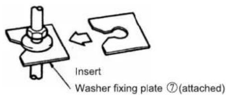
Securing the washer


INSTALLATION OF OUTDOOR UNIT
Notes:
● Try to ship the product to the installation location in its original package;
As the gravity center of the unit is not at the installation center, special caution should be taken when using hoisting cables to lift up the unit;
● During shipping, the outdoor unit must not be slanted to over 45 degrees (Do not store the unit in a horizontal way).
- When the outdoor unit is installed, bolts should be used to fix the feet of the unit (The bolts are to be prepared locally).
- Do the installation firmly so as to prevent earthquake of strong wind from causing the unit to fall.
Refer to the indications in the following figures for specifications of the concrete base.
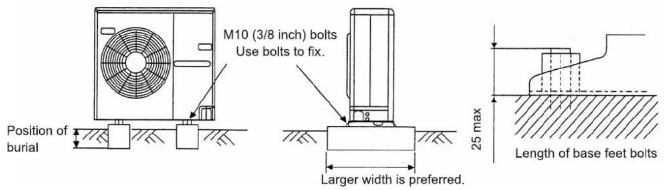
N.B: Measured from the installation base surface on the bottom side to keep the length of the longest foot bolt being 25mm.
Screw hole spaces for parallel installation of the units

INSTALLATION OF REFRIGERANT PIPE AND DRAINAGE TUBE
- Our company accessories for piping lines are recommended in general.
- In some special cases, it is needed to buy thermal insulation materials with a thickness of 9mm minimum and the thermal sheath with good property so as to prevent from dew-dropping.
- When installing the drainage tube (with accessories), power cable casing with inner diameter of 16 should be purchased to connect the drainage tube and use thermal insulation sheath of 9mm minimum thickness to wrap the tube to prevent from dew-dropping.
Dimensions of refrigerant pipe and drainage tube:
| MODEL | Refrigerant liquid pipe | Refrigerant gas pipe | Water drainage tube |
| 2500W | Outer diameter 6.35(1/4") | Outer diameter 9.52(3/8") | Outer diameter 16 |
| 3500W.5100W | Outer diameter 6.35(1/4") | Outer diameter 12.7(1/2") | Outer diameter 16 |
| 7000W.7500W | Outer diameter 9.52(3/8") | Outer diameter 15.88(5/8") | Outer diameter 16 |
| 8800W.11000W | Outer diameter 9.52(3/8") | Outer diameter 19.05(4/5") | Outer diameter 16 |
Piping line construction for refrigerant pipe
1) Indoor units
Sequence of connections of supplementary pipes
-
Keep the gas and liquid valves of the outdoor unit in its original closed state (the ex-factory state); remove the screw nuts of the indoor pipe and outdoor pipe, dust-proof cap and stoppers of the supplementary pipes; make the connections of the bell-mouths quickly (to avoid dust or moisture or other objects from entering the pipes, which might result in faulty operations of the units).
-
When the connection of pipes is made, please use two wrenches. The related torque forces are shown.
- Do the bell-mouth connections one by one until all the refrigerant pipes are well connected.
- Use a small amount of the refrigerant in the main unit to do the evacuation of the pipes.
● After the pipes are connected, you must do the leakage checks by soap water or a special detective device to see if there is any leakage.
CAUSTION: the discharged way should be done according to the refrigerant character. The refrigerant is shown on the nameplate.
R22: When the pipe length is within 5 meters, use the refrigerant inside the unit to discharge the air in the pipes, When the pipe length is above 5 meters, use pump vacuum or refrigerant bottle.
R407C/R410A: Use pump vacuum(special for R407C/R410A) or refrigerant bottle to discharge.
Please have the professional technicians to do the installation for you.
- After the above operations are completed, use a S4 inner hexagonal wrench to turn open the gas and liquid valves of the outdoor unit, which makes the refrigeration loops of the indoor and outdoor unit fully connected.
- The bending of the supplementary pipes should not exceed 90 degrees, and the bending is not allowed to occur more than three times.
Specifications for torque forces
| Outer diameter of copper pipe (mm) | Tightening torque force (N.M) |
| ∅ 6.35 | 145 ~ 175 |
| ∅ 9.52 | 350 ~ 420 |
| ∅ 12.7 | 550 ~ 600 |
| ∅ 15.88 | 750 ~ 800 |
| ∅ 19.05 | 1000 ~ 1400 |

natural_image
Line drawing of a hand holding a tool with a ruler, no text or symbols presentSchematic diagram for the installation of the outdoor unit refrigerant piping system.
- For the thermal installation of the bell-mouth connection in the room, please use the thermal sheat for the refrigerant pipes.
- When the pipes are brazed, the approach of non-oxygen brazing must be adopted.
(1)


(2)
1. Direction of pipe take-out (to be taken out from the 4 side)

- Remove the maintenance plate and guard cover (remove the two screws for each)

- When doing the connections, please do not bend or press the copper pipes. Two wrenches should be used to do the firm fixing (bending curve with radius of 100-150mm/4-6inch)

4. Adjustment of refrigerant volume
When the pipe length is within 5 meters(193 inch), there is no need to add more refrigerant to the unit. When the length is above 5 meters(193 inch), please add more refrigerant according to the allowances indicated in the following table:
| Model | Maximum allowance for length | Additional volume of refrigerant (kg) |
| 2500W.3500W series | <10m(394 inch) | 0.02 kg/m(0.79 kg/inch) |
| 7000W.5100W series | <15m(591 inch) | 0.03 kg/m(1.2 kg/inch) |
| 7500W.8800W.11000W series | <24m(846 inch) | 0.06 kg/m(2.4 kg/inch) |
※When additional refrigerant is filled in, please use the needle valve on the low-pressure valve of the outdoor unit dwring cooling operation.
DRAIN PIPING WORK
Please assure that the drain is unobstructed when installing the drain pipe.
- The diameter of the drain pipe should be greater than or equal to the diameter of the connecting pipe(vinyl tube;pipe size:25 mm;outer dimension:32mm)
- Keep the drain pipe short and sloping sownwards at a gradient of at least 1/100 to prevent air pockets from forming.
- If the drain hose cannot be sufficiently set on a sliope, execute the drain raising piping.
● To keep the drain hose from sagging. keep the distance of 1 to 1.5m between the hangers.

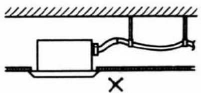
natural_image
Pure technical diagram of a mechanical or electrical component with no text, numbers, or symbols● Use the attached drainage 1 and clamp 2.
Insert the drain hose into the drain socket, up to the white tape
● Water will leak when condenses, so do insulate these two following spaces
● The drain pipe across the house inside
● The socket of the drain pipe
Refer to the following illustration, insulate the clamp and drain hose with the attached large sealing pad 10.


PRECAUTIONS FOR DRAIN RAISING PIPING
● Install the drain raising pipes at a height of less than (A-200) mm
● Install the drain raising pipes at a right angle and no more than 330mm from the unit.

A=400mm(2500W.3500W.5100W)
A=750mm(7000W.7500W.8800W.11000W)
CAUTION
- Don't let the attached drain hose 1 stand additional force or distort or screw.(that will cause water leakage.)
- If converging multiple drain pipes.install according to the procedure shown below

Select converging drain pipes whose gauge is suitable for the operating capacity of the unit.
After piping work is finished, check if drainage flows smoothly.
- From the air discharge outlet or the inspection opening, add approximately 2000cc of water slow check drainage flow.
WHEN ELECTRIC WIRING WORK IS FINISHED
- Check drainage flow during COOL operation, explained under "TEST RUNNING".
Method of adding water

Adding water through air discharge outlet
INSTALLATION OF ELECTRIC COMPONENTS
Points of attention
● Special purpose power source should be utilized along with proper breaker installation;
● Make sure of the applicable voltage and cables or wires for the specific model to be used, before doing the connections;
- Read the prompts at the terminal board for wiring. Make sure the wiring is done correctly.
- Do not connect the signal terminal of the indoor and outdoor units to the 220V power, which might result in faulty performances.
● Pay attention to the poles of the signal terminal and connect the terminals to match the identification numbers.
- When the wiring connections are wrong, the compressor will not work.
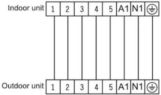
Schematic diagram for electric wire connections (Refer to the following diagrams for different models of machine and different conditions of the end-users). Example I: (for single-phase model)
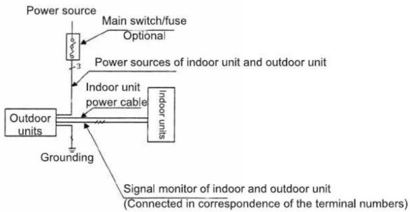
Example II: (for single and three-phase models)

The two figures only for reference.
INSTALLATION OF ELECTRIC COMPONENTS
Cable connections for indoor unit
- Remove the cover of the electric box of the indoor unit;
- Connect the power cable and signal wire to the corresponding terminals;
- Open the wire clamp on the fixing plate and press the power cable and the signal wire firmly onto the plate;
- install the cover of the electric box back to place.
Connection of control wires of the outdoor unit(for reference)
2500W.3500W.5100W

7000W.7500W.8800W(1 phase)

flowchart
graph LR
    A["Power Source"] --> B["Switch"]
    B --> C["L"]
    B --> D["N"]
    B --> E["⊕"]
    C --> F["Breaker"]
    D --> F
    E --> F
7000W.7500W.8800W.11000W(3 phase)


flowchart
graph LR
    A["Power Source"] --> B["L1"]
    A --> C["L2"]
    A --> D["L3"]
    A --> E["N"]
    A --> F["Switch"]
    A --> G["Breaker"]
    G --> H["Output"]
    style A fill:#f9f,stroke:#333
    style G fill:#ccf,stroke:#333
Note:
- The environment conditions must be taken into consideration when the connections of power cable are made (such as the ambient temperature, direct exposure to heat/direct exposure to sunlight);
- The specifications for the power cable refer to the minimum values of the metal core wires. Taking into consideration the voltage losses, the core wire of power cable must be one size larger than the specifications;
● The grounding wire must be connected to the indoor units and outdoor units; - The laying of power cables must be done by qualified electricians and comply with the regulations of the local power supply authorities and with the standards of the electric appliances;
- If the power cable is damaged, please contact our company dealer or the authorized maintenance shop for replacement by special wires.
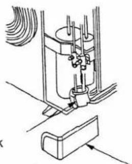
Power cable connections for the outdoor unit
Remove the maintenance plate (2 screws).
The power cable can be led out either from the rear hole for supplementary pipes or from the hole at the top.

When the power cable is led out from the rear side, please use the outdoor piping line support.

natural_image
Technical line drawing of a mechanical assembly with no visible text or symbolsOutdoor piping line support (When the power cable is led out from other places, do not use the outdoor piping line support).
After the installation of the supplementary pipes and cables is completed, seal with a sponge block as shown.
Sponge block
natural_image
Technical line drawing of a mechanical assembly with no visible text or symbolsSupplementary pipe cover
PREPARATION OF DECORATION PANEL
(for model 7000W\~11000W)
HANDLING OF DECORATION PANELS
Never place the panel facing down nor lean it against a wall nor leave it on a projecting object. Never touch or put pressure on the swing flap.(The swing flap may malfunction)
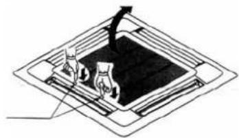
(1) Remove the suction grille from the decoration panel. Push the suction grille lever inward and lift up the lever side. (Refer to Fig.1)
natural_image
Diagram of a mechanical assembly with two components and a central component (no text or symbols)Fig.1
(2) Detach the suction grille from the decoration panel by lifting the grille up approximately 45 degrees. (Refer to Fig.2)

natural_image
Diagram of a geometric structure with a tilted top frame and an arrow indicating direction (no text or symbols)Fig.2
(3) Remove the service cover on the corner. Slide the service cover outward to remove.(Refer to Fig.3)

natural_image
Simple line drawing of a stack of papers or documents with no visible text, numbers, or symbols.Fig.3
INSTALLATION OF THE DECORATION PANEL TO THE INDOOR UNIT BODY
Refer to the installation manual attached to the indoor unit for the installation of the indoor unit.
(1) Set the decoration panel to the indoor unit body by matching the position of the swing flap motor of the decoration panel to the piping position of the indoor unit as shown in Fig.4.
(2) Install the decoration panel
- Temporarily install the decoration panel to the indoor unit by hanging the latch on the opposite side of the swing flap motor of the decoration panel to the hook of the indoor unit body.(2 positions)
- Temporarily hang the remaining 2 latches to the hooks on the sides of the indoor unit.(Be careful not to let the swing motor lead wire get caught in the sealing material.)
● Screw all 4 hexagon head screws located right beneath the latches in approximately 5 mm.(Panel will rise) - Adjust the decoration panel by turning it to the arrowed direction in Fig.4 so that the ceiling opening is completely covered.
● Tighten the screws until the thickness of the sealing material between the decoration panel and the indoor unit body reduces to 5-8 mm.

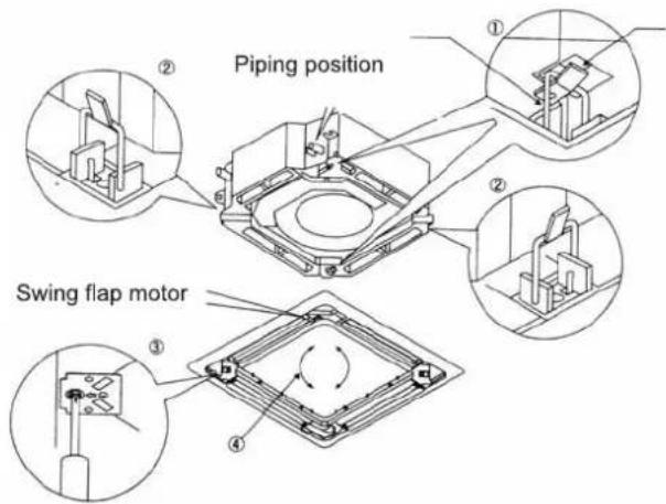
Fig.4
PRECAUTIONS
Improper screwing of the screws may cause the troubles shown in Fig.5. Screw properly.
If gap is still left between the ceiling and the decoration panel after screwing the screws, readjust the indoor unit body height, (Refer to Fig.6)
Adjustment of the indoor unit body height from the holes in the corner of the decoration panel is possible if the indoor unit is kept leveled and the drain piping, etc. is unaffected.
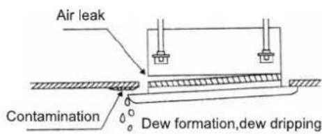
Fig.5


Fig.6

natural_image
Illustration of a hand holding a pen and writing on paper with a small object inside, no text or symbols present.INSTALLATION OF DECORATION PANEL
About the suspend height of indoor unit
Please adjust the suspend height of indoor unit, make sure the distance from downside of indoor unit to downside of ceiling as shown in fig.

In addition
Clearance between indoor unit and panel cause bad results as shown below.
(1) Because of air induction from ceiling or cold air leakage to ceiling the outside of indoor unit (upside of ceiling part) and inside of indoor unit have dew condensation.
(2) Turbulent flow of discharged air cause dew condensation on horizontal blades, dew drop splash and dew condensation inside of indoor unit.
(3) Wiring of the decoration panel (Refer to Fig. 7)
Connect the connectors for swing flap motor lead wire installed on the decoration panel.
If connectors are not connected, the swing flap will not operate. Connect the connectors properly.
Make sure that the swing flap motor lead wire is not caught between the indoor unit and the decoration panel.
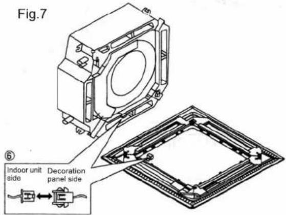
Wiring Instruction Diagram
(It differs from the actual state)
INSTALLATION OF SUCTION GRILLE AND SERVICE COVER
(1) Install the suction grille
Install by reversing the procedure shown in "PREPARATION OF DECORATION PANEL".
It is possible to install the suction grille in 4 directions by turing the suction grille.
Change the direction when adjusting the direction of the suction grille of multiple units or in meeting customers' demands.
NOTE:
Be careful not to get swing flap motor lead wire get caught when installing the suction grille.
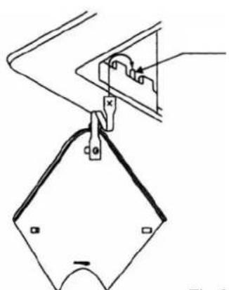
Install the service cover on the corner. Attach the string of the service cover to the pin of the decortion panel as in Fig.8.
natural_image
Technical line drawing of a mechanical clamp or bracket assembly (no text or symbols)Fig.8
Install the service cover the decoration panel.(Refer to Fig.9)

Fig.9
Installation for model 2500W\~5100W
1. Remove air-intake grid
- Simultaneously slide the 2 grid switches to the middle position, and then raise it up (see Figure 10).
- Raise up the air-intake grid to about 45^ , and remove the air-intake grid (see Figure 11).

Figure 10

natural_image
Diagram of a device with a 45-degree angle标注, showing layered structure without any text or symbols.Figure 11
2. Remove the installation cover plate at four corners
Screw out the screws, loosen the rope of installation cover plate, and take out the installation cover plate outward (see Figure 12)
Figure 12

natural_image
Line drawing of a mechanical assembly with no visible text or symbols3. Front panel installation
- Align the rocking motor on front panel with the joint of the piping on main body (see Figure 13);
- During installation, firstly hang the front panel hooks close to the side of rocking motor and the opposite side onto the corresponding hooks of the water pan (as shown in Figure 13 ①), and then hang the other two front panel hooks onto the corresponding suspension brackets of main body (as shown in Figure 13 ②);
Causing: the wire of rocking motor into retaining rings of front panel;
- Clamp the wire of rocking motor into retaining rings of front panel;
- Adjust the 4 screws of front panel hook to ensure that the front panel is level and evenly raised close to ceiling board (as shown in Figure 13 ③);
- Slightly adjust the front panel as per the direction indicated by the arrow in (Figure 13 ④) in order that the center of front panel coincides with the center of opening in ceiling board; confirm that the hooks at four corners have already been hung properly;
Causing: Never immix the wire of rocking motor into sealing sponge;

Figure 13

Figure 14
- Continue to evenly screw down the screws below front panel hook till the thickness of foam air outlet between main body and front panel is reduced to about 4\~6mm, and that the edges of front panel contact the surface of ceiling board properly (see Figure 14);
○ Inappropriate screw-down of screws may lead to the faults shown in Figure 15;

Figure 15
INSTALLATION OF DECORATION PANEL
○ If there exists gap between ceiling board and front panel after screws are retained, the height of indoor unit must be re-adjusted (see left side in Figure 16);
○ If indoor unit's adjustment for levelness and drain pipe are not affected, the height of indoor unit can be adjusted through the openings at 4 corners of the front panel (see right side in Figure 16);

Figure 16
- Firstly hang the air-intake grid onto the front panel, and according to connect the pigtail splices of rocking motor and control box on front panel to corresponding joints of main body;
- Reassemble the air-intake grid in reverse procedures for removing the air-intake grid;
- Reassemble the installation cover plate;
- To tight up the rope of installation cover plate onto the pin of installation cover plate with screws (see left side in Figure 17);
- Slightly press the installation cover plate into front panel (see Figure 17);
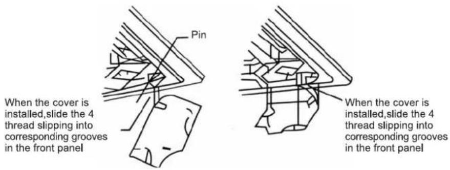
Figure 17
TEST RUNNING
1) Confirmation prior to the test running
When the installations of the indoor unit and outdoor unit as well as the connections of pipes and wires are completed, check once again to see if there is any leakage of refrigerant, or if the connections or fixtures of the power cable and signal wire are loose, or if the poles of power source are correctly matched.
N.B: When the wires are connected incorrectly, the compressor will not work.
2) Test running
● Connect the main power supply of the units;
- Press the emergency operation button (cooling or heating) and the machine will be activated and the operation indication light will be on. Check to see if the machine units are working regularly. Press the emergency operation button once again and the machine will stop operating.
- Press the ON/OFF button on the remote controller to make sure that the indoor unit utters the "bee.." acknowledging sound. If so, the remote controller is functioning. The emergency operation mode is deleted. Then operate the machine by using various control buttons on the remote controller. Watch closely if the operational modes correspond to the control signals.
- Press the "MODE" button to select (ventilation) mode, and check if there is air delivered from the air conditioner;
- Press the "MODE" button to select (cooling) mode, and check if there is cool air delivered from the air conditioner;
- Press the "MODE" button to select (heating) mode, and check if there is warm air delivered from the air conditioner (The cooling-only models do not have this mode).
- Press the "FAN SPEED" button to select (high speed) mode, and check if there is strong air delivered from the air conditioner;
● Press the "SWING" button and check if the air grids swing properly.
- Press the "ON/OFF" button once again and the test running is stopped.
3) Testing the water drainage devices
- When the installation of the machine is completed, the water drainage device must be tested.
● During the test running, the water should be properly drained and make sure that there is no water dropping from the joints.
After the test running is completed, make a briefing to the end-user about the operation methods and points of attention in accordance with the Operation Manual.
- Thank you for choosing MaxiCool products!
- CONTENTS
- INSTRUCTIONS TO END-USERS
- NAMES OF PARTS AND THEIR FUNCTION
- USE OF REMOTE CONTROLLER
- Operating Machine In selected modes
- PRESENT TIME SETTING PROCEDURE
- SLEEP OPERATION PROCEDURE
- NOTE:
- TIMER OPERATION PROEDURE
- Timed switch-off
- Timed switch-on
- Releasing procedure
- REPLACEMENT OF BATTERIES
- HOW TO GET THE OPTIMIZED PERFORMANCES
- Clean the air filter screen from time to time
- Cleaning steps:
- Set the room temperature at a comfortable setting.
- Try to avoid the heat sources as much as you can.
- Keep the room air exchanged from time to time.
- - Clean the indoor units
- The procedure of opening the suction grille and removing the air filter
- METHOD OF MAINTENANCE AND SERVICING
- Inspections during operational seasons
- PHENOMENA ANALYSIS AND TREATMENT
- Analysis on faulty performances
- Self diagnosis function
- The following phenomena are not faulty operational performances:
- SELECTION OF INSTALLATION POSITION
- Selection of installation for the indoor unit
- Selection of installation position for outdoor unit (consult the end-user)
- Installation and maintenance spaces for the outdoor unit
- When a single unit is installed:
- When there are blocking objects above
- When the front (air outlet) is open
- When there are blocking objects only in front
- When there are blocking objects in the front and rear
- When there are blocking objects only in the front and rear
- When there are blocking objects all round the unit
- BEFORE INSTALLATION
- SELECTING INSTALLATION SITE
- Height of ceiling
- INSTALLATION OF INDOOR UNIT
- Relation of ceiling opening to unit and suspension bolt position
- For new ceilings
- For existing ceilings
- INSTALLATION OF OUTDOOR UNIT
- Notes:
- INSTALLATION OF REFRIGERANT PIPE AND DRAINAGE TUBE
- Piping line construction for refrigerant pipe
- 1) Indoor units
- Adjustment of refrigerant volume
- DRAIN PIPING WORK
- PRECAUTIONS FOR DRAIN RAISING PIPING
- CAUTION
- WHEN ELECTRIC WIRING WORK IS FINISHED
- Method of adding water
- INSTALLATION OF ELECTRIC COMPONENTS
- Points of attention
- Cable connections for indoor unit
- Connection of control wires of the outdoor unit(for reference)
- Power cable connections for the outdoor unit
- PREPARATION OF DECORATION PANEL
- (for model 7000W\~11000W)
- HANDLING OF DECORATION PANELS
- INSTALLATION OF THE DECORATION PANEL TO THE INDOOR UNIT BODY
- PRECAUTIONS
- INSTALLATION OF DECORATION PANEL
- About the suspend height of indoor unit
- In addition
- INSTALLATION OF SUCTION GRILLE AND SERVICE COVER
- Installation for model 2500W\~5100W
- Remove air-intake grid
- Remove the installation cover plate at four corners
- Front panel installation
- Causing: the wire of rocking motor into retaining rings of front panel;
- Causing: Never immix the wire of rocking motor into sealing sponge;
- TEST RUNNING
- 1) Confirmation prior to the test running
- 2) Test running
- 3) Testing the water drainage devices
Merk : Maxicool
Model : CCH50H4C
Categorie : Airconditioner