
KX-2501A - 177 SONY - Panduan pengguna gratis
Temukan panduan perangkat secara gratis KX-2501A SONY dalam format PDF.


Pertanyaan pengguna tentang KX-2501A SONY
0 pertanyaan tentang perangkat ini. Jawab yang Anda tahu atau ajukan milik Anda sendiri.
Ajukan pertanyaan baru tentang perangkat ini
Unduh instruksi untuk 177 dalam format PDF gratis! Temukan panduan Anda KX-2501A - SONY dan ambil kembali perangkat elektronik Anda. Di halaman ini diterbitkan semua dokumen yang diperlukan untuk penggunaan perangkat Anda. KX-2501A merek SONY.
PANDUAN PENGGUNA KX-2501A SONY
SERVICE MANUAL

US Model
Chassis No. SCC-383B

natural_image
Black rectangular object with white border and faint texture, no visible text or symbolsMay, 1983
HF CHASSIS
The adjustment procedures are not contained in this manual. When performing the adjustments, refer to the separate-volume "ADJUSTMENT MANUAL".
SPECIFICATIONS
Color system
Picture tube
NTSC
Trinitron tube
25-Inch picture measured
diagonally, 114-degree
deflection
Inputs
VIDEO INPUT (phono jack)
1 V p-p, NTSC, 75 ohms,
unbalanced, sync negative
AUDIO INPUT (2 phono jacks)
726mVrms (100% modulation), 47 kilohms
CONTROL INPUT (minijack)
5V p-p
MULTI INPUT (8-pin DIN)
Same as the above VIDEO/AUDIO/
CONTROL INPUTS
Output
SPEAKER
Accepts speakers of 8–16 ohms
120V ac, 60 Hz
180 W (max.) 132 W (average)
1.8 (in standby condition)
Switched, max. 200 W
Approx. 660 × 560 × 487 mm (w/h/d)
(26 × 22 ^1/8 × 19 ^1/4 inches)
Approx. 55 kg (121 lb 4 oz)
Accessories supplied Video Cable VMC-1S
(phono plug to phono plug, 1.2 m)
Connecting Cord RK-105A
(miniplug to 2 phono plugs, 1.5 m)
34-pin socket 1 set
Design and specifications subject to change without notice.
- Continued on next page -
TRINITRON®
COMPONENT TV
SONY.


SECTION 1
GENERAL
1-1. FEATURES

The KX-2501A also features:
● A Velocity Modulation scanning system for increased sharpness and resolution.
- Pulse techniques in the power supply section that provide an efficient and stable power supply.
1-2. LOCATION AND FUNCTION OF PARTS AND CONTROLS
behind panel

rear view
RGB MULTI INPUT connector
15 AUDIO INPUT jacks
16 VIDEO INPUT jack
⑰ INPUT LEVEL control
16 CONTROL INPUT jack
⑬ MULTI INPUT connector
20 SPEAKER terminals
② AC OUTLET
⑰ AC power cord
② POWER LOCK switch
② BASS BOOST switch
Speaker attachment holes
(Also located on the opposite side.)


14 RGB MULTI INPUT connector (34-pin plug)
This connector allows a character generator, microcomputer, or a special adaptor for future videotex/teletext having digital/analog RGB outputs to be connected.
The connector cover has been attached to this connector at the factory. When this connector is not in use, keep the cover attached.
When such equipment having digital/analog RGB outputs is connected to this connector, disconnect the connector cover and proceed as follows by using the supplied 34-pin socket.
34-pin socket parts

Cover B


Cord clamper
Socket contacts
(17×2)

| Position number | Signal to be connected |
| 1,2 | +5V power supply |
| 3 | Audio (R) input ground |
| 4 | Ground |
| 5 | Remote control ground |
| 6 | Composite video output ground |
| 7 | Audio (L) input ground |
| 8*,9*,10* | Ground |
| 11 | Ground |
| 12*,13* | Ground |
| 14 | Not in use |
| 15* | Ground |
| 16 | Ground |
| 17 | Not in use |
| 18 | EXT/INT mode sync switch |
| 19 | Not in use |
| 20 | Audio (R) input |
| 21 | Analog/digital mode select |
| 22 | Remote control output |
| 23 | Composite video output |
| 24 | Audio (L) input |
| 25* | Red input |
| 26* | Green input |
| 27* | Blue input |
| 28 | Not in use |
| 29* | Blanking input |
| 30* | H. sync or composite sync |
| 31* | V. sync |
| 32 | Half blanking input |
| 33 | RGB/NORMAL mode select |
| 34 | Audio select |
*For No. 8 and 25, 9 and 26, 10 and 27, 12 and 29, 13 and 30, or 15 and 31 connections, use a twisted-pair lead when the signal level is TTL, or a 75-ohm coaxial cable when the signal level is 1 V p-p.
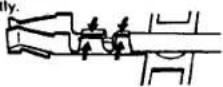
(1) Solder each lead to a socket contact.
- Place the lead on the contact as illustrated.

-
Fix the lead.
-
Tighten the tabs
slightly
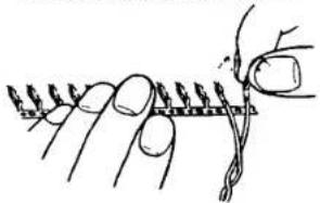
- Solder the conductor.
Take care not to solder past the point indicated by the dotted line.

- After soldering, separate the contact by moving it upwards and downwards.
natural_image
Line drawing of a finger pressing down on a textured surface (no text or symbols)(2) Connect the socket contacts to the correct positions. Refer to the chart.
Align the contact and read for easier insertion.

(3) Assemble the socket.
- Attach the socket to the cover B.
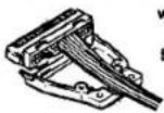
with the positions 1–17 upwards
Engage the projections with the holes.
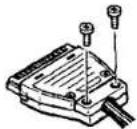
- Attach the cover A to the socket with the 2 shorter screws.

Engage the projections with the holes.
- Attach the cord clamper with the 2 longer screws.
(4) Connect the socket to the RGB MULTI INPUT connector.
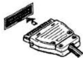
Engage the projection with this slot.
For the signal specifications, see page 2.
Example 1

flowchart
graph TD
    A["Microcomputer (TTL)"] --> B["R"]
    A --> C["G"]
    A --> D["B"]
    A --> E["H sync"]
    A --> F["V sync"]
    B --> G["Red (25)"]
    B --> H["Green (26)"]
    B --> I["Blue (27)"]
    C --> J["Ground (8)"]
    C --> K["Ground (9)"]
    C --> L["Ground (10)"]
    D --> M["Ground (13)"]
    D --> N["V sync (31)"]
    D --> O["Ground (15)"]
    E --> P["H sync (30)"]
    E --> Q["Ground (13)"]
    E --> R["Ground (10)"]
    F --> S["Ground (4)"]
    F --> T["Analog/digital mode select (21)"]
Example 2

flowchart
graph TD
    A["Microcomputer (analog)"] --> B["Open"]
    B --> C["Component TV 34-pin connector"]
    subgraph Component TV
        D["Analog/digital mode"] --> E["select (21)"]
        F["Ground (4)"] --> G["Red (25)"]
        H["Green (26)"] --> I["Blue (27)"]
        J["H. sync (30)"] --> K["Ground (13)"]
    end
    subgraph Component TV
        L["Composite sync"] --> M["Ground (13)"]
    end
15 AUDIO INPUT jacks (phono jacks, L-white, R-red)
Connect to the audio outputs of a Sony Betamax or U-matic video cassette recorder, Sony Component TV tuner, etc. Connect the L and R channels properly. If the recorder is monaural, connect the audio output of the recorder to these two jacks with the RK-105A Connecting Cord (supplied) and the PC-5A Plug Adaptor (phono plug to minijack, optional), if required.
16 VIDEO INPUT jack (phono jack, yellow)
17 INPUT LEVEL control
Connect to the video output of a Sony Betamax or U-matic video cassette recorder, Sony Component TV tuner, video camera, etc. with the VMC-1S Video Cable (supplied).
The input level of the video signal from this jack can be adjusted with the INPUT LEVEL control.
Normally set the control to the center detent position.
If the picture contrast is too weak or too strong, adjust the level (min. 0.5V p-p, max. 2V p-p) by turning the control clockwise or counterclockwise with a screwdriver.
13 CONTROL INPUT jack (minijack)
When the set is used with a Sony Component TV tuner equipped with a control output connector, connect as illustrated with the RK-69A Connecting Cord (optional).
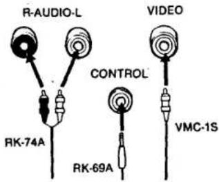
The volume and picture can be adjusted and the power can be turned on or off using the controls on the TV tuner or the Remote Commander (supplied with the tuner).
⑲ MULTI INPUT connector (8-pin DIN)
Connect to the MULTI OUTPUT (8-pin DIN) connector on a Sony Component TV tuner with the VK-2D Video Cable (supplied with the tuner, 2 m). The audio, video and control signals can be connected simultaneously with this cable.
The volume and picture can be adjusted and the power can be turned on or off using the controls on the TV tuner or the Remote Commander (supplied with the tuner).
Engage this projection with this slot.
To disconnect, push this button.

The VK-5DX Video Cable is available optionally for extending the VK-2D.
Caution: Use either the VIDEO/AUDIO/CONTROL ⑬ ⑮ jacks or the MULTI INPUT connector, but not both simultaneously.

SPEAKER terminals
Connect to an 8-16 ohms speaker system.
Speaker cord connections

Caution
● Make sure that none of the strands are separated from the wire and shorts across the speaker terminals.
- Correct connection of both speakers insures proper in-phase operation. If the speaker system is out-of-phase, the bass tones seem to be missing and the position of the instruments becomes obscure.
● The set should be placed some distance away from the speakers so that it will not be affected by the speaker magnets.
If a temporary proximity to magnets should cause portions of the picture to have poor color, turn the POWER button off, and after about 10 minutes, turn it on.
The Sony SS-X1A and SS-X10A Speaker System (optional) may be placed near the set because these are a low magnetic flux leakage type.
- Never connect a speaker system to an amplifier and this Component TV simultaneously, as this may damage the TV.


AC OUTLET (SWITCHED)
Provides ac power of 200 W max. (KX-2501A) or 250 W max. (KX-1901A) to other connected equipment. Power can be switched on or off with the POWER button on the Component TV.
Caution
- When the set is used with a Sony Component TV tuner, do not connect the ac power cord of the tuner to this outlet. Otherwise, the power cannot be turned on or off using the control on the tuner or the Remote Commander (supplied with the tuner).

flowchart
graph TD
    A["Component TV tuner"] --> B["to AC OUTLET"]
    B --> C["Component TV"]
    style A fill:#f9f,stroke:#333
    style C fill:#ccf,stroke:#333
- Do not connect electrical home appliances such as an electric iron, fans, or other high-wattage equipment to this outlet.

AC power cord
Connect to a convenient 120 V ac wall outlet.
When the set is used with a Sony Component TV tuner, the ac power cord may be connected to the UNSWITCHED AC OUTLET.

flowchart
graph TD
    A["Component TV tuner"] -->|to UNSWITCHED AC OUTLET| B["Switch"]
    C["Component TV"] --> D["AC Wall Outlet"]
    D --> E["Output"]

POWER LOCK switch
Normally set to OFF.
The MASTER and POWER buttons functions as described above. If the set is to be switched on or off by a timer, set this switch to ON and keep the MASTER button pushed in.
When power is supplied to the set with the POWER LOCK switch and MASTER button set to ON, the set will turn on automatically.

BASS BOOST switch
When a bookshelf-type speaker system (e.g. Sony SS-X1A, SS-X10A) is used, set this switch to ON to enhance the bass sound. When a larger speaker system is used, set the switch to OFF to prevent excessive bass boost.

Speaker attachment holes
The Sony SS-X1A Speaker System (optional) may be attached to the set. For details on attachment, see the instructions furnished with the SS-X1A.


- SERVICE MANUAL
- HF CHASSIS
- SPECIFICATIONS
- SECTION 1
- GENERAL
- 1-1. FEATURES
- 1-2. LOCATION AND FUNCTION OF PARTS AND CONTROLS
- RGB MULTI INPUT connector (34-pin plug)
- Solder each lead to a socket contact.
- Assemble the socket.
- CONTROL INPUT jack (minijack)
- ⑲ MULTI INPUT connector (8-pin DIN)
- SPEAKER terminals
- Caution
- AC OUTLET (SWITCHED)
- AC power cord
- POWER LOCK switch
- BASS BOOST switch
- Speaker attachment holes
Merek : SONY
Model : KX-2501A
Kategori : 177