DL251 - Keverőpult DRAWMER - Ingyenes használati útmutató
Találja meg az eszköz kézikönyvét ingyenesen DL251 DRAWMER PDF formátumban.

Felhasználói kérdések a következőről DL251 DRAWMER
0 kérdés erről a készülékről. Válaszolj azokra, amiket ismersz, vagy tedd fel a sajátod.
Tegyél fel egy új kérdést erről a készülékről
Töltse le az útmutatót a következőhöz Keverőpult PDF formátumban ingyenesen! Találja meg kézikönyvét DL251 - DRAWMER és vegye vissza elektronikus eszközét a kezébe. Ezen az oldalon közzé van téve az eszköze használatához szükséges összes dokumentum. DL251 márka DRAWMER.
HASZNÁLATI ÚTMUTATÓ DL251 DRAWMER
DRAWMER
DL251
DUAL SPECTRAL COMPRESSOR
OPERATORS MANUAL
CONTENTS
SAFETY CONSIDERATIONScpage 1
INTRODUCTIONcpage 2
INSTALLATIONcpage 3
CONTROL DESCRIPTIONScpage 5
- Compressor page 5
• Dynamic Spectral Enhancement page 6
• Peak Limit page 7 - Stereo Link page 7
SIDE CHAIN INSERT JACKcpage 8
OPERATIONcpage 9
CREATIVE APPLICATIONScpage 11
IF A FAULT DEVELOPScpage 12
CONTACTING DRAWMERcpage 12
TECHNICAL SPECIFICATIONcpage 13
BLOCK DIAGRAMcpage 14
COPYRIGHT
This manual is copyrighted © 1997 by Drawmer Electronics, Ltd. With all rights reserved. Under copyright laws, this manual may not be duplicated in whole or in part without the written consent of Drawmer.
ONE YEAR LIMITED WARRANTY
Drawmer cElectronics cLtd., cwarrants cthe cDrawmer cDL251 caudio cprocessor cto conform substantially to the specifications of this manual for a period of one year from the original date of purchase when used in accordance with the specifications detailed cin cthis cmanual. cln cthe ccase cof ca cvalid cwarranty cclaim, cyour csole cand exclusive remedy and Drawmer's entire liability under any theory of liability will be to, at Drawmer's discretion, repair or replace the product without charge, or, if not possible, to refund the purchase price to you. This warrant transferable. It applies only to the original purchaser of the product.
For warranty service please call your local Drawmer dealer. Alternatively call Drawmer Electronics Ltd. at +44 (0)1709 527574. Then ship the defective product, with transportation and insurance charges pre-paid, to Drawmer Electronics Ltd., Coleman Street, Parkgate, Rotherham, S62 6EL UK. Write the RA number in large letters in a prominent position on the shipping box. Enclose your name, address, telephone number, copy of the original sales invoice and a detailed description of the problem. Drawmer will not accept responsibility for loss or damage during transit.
This warranty is void if the product has been damaged by misuse, modification or unauthorised repair.
THIS WARRANTY IS IN LIEU OF ALL WARRANTIES, WHETHER ORAL OR WRITTEN, EXPRESSED, cIMPLIED cOR cSTATUTORY. cDRAWMER c cMAKES cNO cOTHER WARRANTY EITHER EXPRESS OR IMPLIED, INCLUDING, WITHOUT LIMITATION, ANY IMPLIED WARRANTIES OF MERCHANTABILITY, FITNESS FOR A PARTICULAR PURPOSE, cOR cNON-INFRINGEMENT. cPURCHASER'S cSOLE cAND cEXCLUSIVE REMEDY UNDER THIS WARRANTY SHALL BE REPAIR OR REPLACEMENT AS SPECIFIED HEREIN.
IN NO EVENT WILL DRAWMER ELECTRONICS LTD. BE LIABLE FOR ANY DIRECT, INDIRECT, SPECIAL, INCIDENTAL OR CONSEQUENTIAL DAMAGES RESULTING FROM ANY DEFECT IN THE PRODUCT, INCLUDING LOST PROFITS, DAMAGE TO PROPERTY, cAND, cTO cTHE cEXTENT cPERMITTED cBY cLAW, cDAMAGE cFOR PERSONAL INJURY, EVEN IF DRAWMER HAS BEEN AI POSSIBILITY OF SUCH DAMAGES.
Some cstates cand cspecific ccountries cdo cnot callow cthe cexclusion cof cimplied warranties or limitations on how long an implied warranty may last, so the above limitations may not apply to you. This warranty gives you specific legal rights. You may have additional rights that vary from state to state, and country to country.
In the interests of product development, Drawmer reserve the right to modify or improve specifications of this product at any time, without prior notice.
DRAWMER DL251
Dual Spectral Compressor
SAFETY CONSIDERATIONS

CAUTION - MAINS FUSE
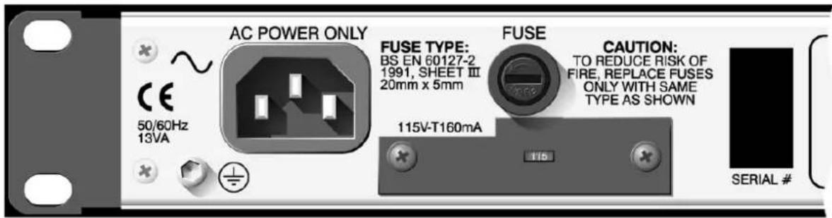
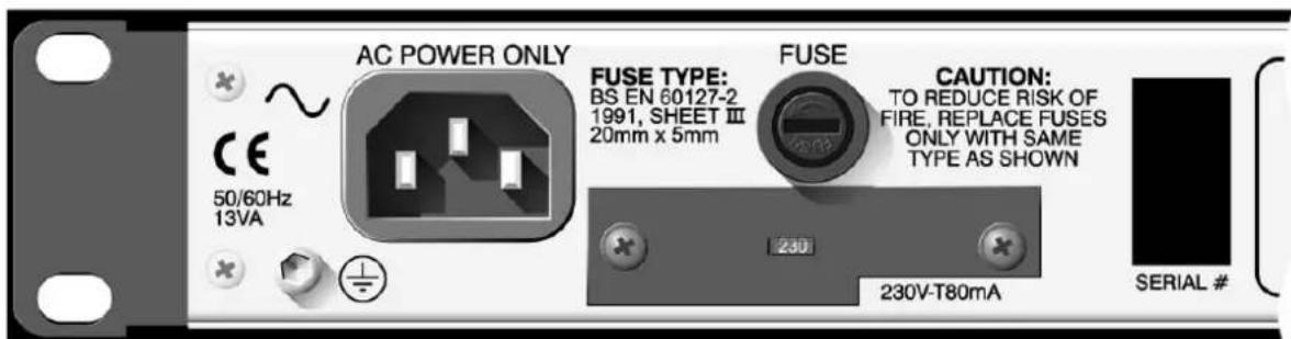
TO REDUCE THE RISK OF FIRE REPLACE THE MAINS FUSE ONLY WITH THE SAME TYPE, WHICH MUST BE A CLASS 3, 230 VOLT, TIME DELAY TYPE, RATED AT 50mA WHERE THE MAINS INPUT VOLTAGE SWITCH IS SET TO 230 VOLTS AC. AND 100mA WHERE THE MAINS INPUT VOLTAGE IS 115 VOLTS AC. ALL FUSES MUST COMPLY WITH BS EN 60127-2:1991, SHEET III. THE FUSE BODY SIZE IS 20mm x 5mm.
CAUTION - MAINS CABLE
DO NOT ATTEMPT TO CHANGE OR TAMPER WITH THE SUPPLIED MAINS CABLE.
CAUTION - SERVICING
DO NOT PERFORM ANY SERVICING. REFER ALL SERVICING TO QUALIFIED SERVICE PERSONNEL.
WARNING
TO REDUCE THE RISK OF FIRE OR ELECTRIC SHOCK DO NOT EXPOSE THIS EQUIPMENT TO RAIN OR MOISTURE.


INTRODUCTION
Designed to meet the needs of professional studio and live sound applications, the DRAWMER DL251 dual channel compressor/limiter has many advanced features including the choice of hard-knee or soft-knee characteristics, an automatic attack and release mode, and Dynamic Spectral Enhancement to maintain transient detail during compression conditions.
The DL251 may be used in either balanced or unbalanced systems and each channel is independently switchable between +4dBu and -10dBV operating levels. In addition to the compressor/limiter, each channel also contains an independent, full-wave peak limiter.
Because the compressor section offers a choice of traditional hard-knee, ratio style compression or csoft-knee ccompression, cit cis cequally cadept cat ccreative cwork cand unobtrusive level control. The control lay-out follows that of a ratio style unit, but when the soft-knee characteristic is switched in, the transition from unity gain to gain reduction at the selected ratio is progressive and occurs over a nominal 10dB input level range.
Soft-knee compressors are often chosen in applications that call for inconspicuous level ccontrol cwhereas cratio ctype ccompressors care cgenerally cconsidered cmore successful in creative applications or where large amounts of gain reduction are required. By offering both alternatives, the DL251 is capable of outstanding results in a very wide range of studio and live sound situations.
A feature of the DL251 is a highly effective peak limiter which allows the user to set an cabsolute coutput clevel cthat ccan cnever cbe cexceeded. cThis cfacility cis cextremely valuable both in live sound applications, for driver protection, and in digital recording where an absolute maximum recording level exists. Furthermore, when the unit is deliberately driven into limiting, it can be used creatively to produce level 'pumping' effects.
The cDL251 calso cincludes cthe cnewly cdevelop Dynamic Spectral Enhancement system which is designed to compensate for the loss of transient detail that tends to occur during periods of heavy compression. This system is dynamically related to the degree of gain reduction taking place which means that processing is applied only when cneeded, cand cthe cdegree cof enhancement cis cset cusing cjust ca csingle crotary control.
INSTALLATION
The DL251 is designed for standard 19" rack mounting and occupies 1U of rack space. Avoid mounting the unit directly above power amplifiers or power supplies that radiate significant amounts of heat and always connect the mains earth to the unit. Fibre or plastic washers may be used to prevent the front panel becoming marked by the mounting bolts.
AUDIO CONNECTIONS
INPUTS and OUTPUTS: Both the input and output XLRs may be used either balanced or unbalanced, the wiring convention being: pin 1 Ground, pin 2 Hot and pin 3 Cold. The crear cpanel cpush cbuttons cshould cbe creleased c(out) cfor c+4dBu coperation cor depressed (in) for -10dBV operation in order to optimise the internal gain structure of the unit. For use with unbalanced systems, the Cold pin (3) must be grounded at both input and output XLRs.
If earth loop hum problems are encountered, don't disconnect the mains earth but instead, try disconnecting the signal screen on the cables connecting the DL251 to the patchbay. If such measures are necessary, balanced operation is recommended.
S/C INSERT: The side-chain insert point is configured as a stereo jack socket wired tip return, ring send. This point is unbalanced and would normally be connected to a normalised or semi-normalised pair of patchbay contacts.
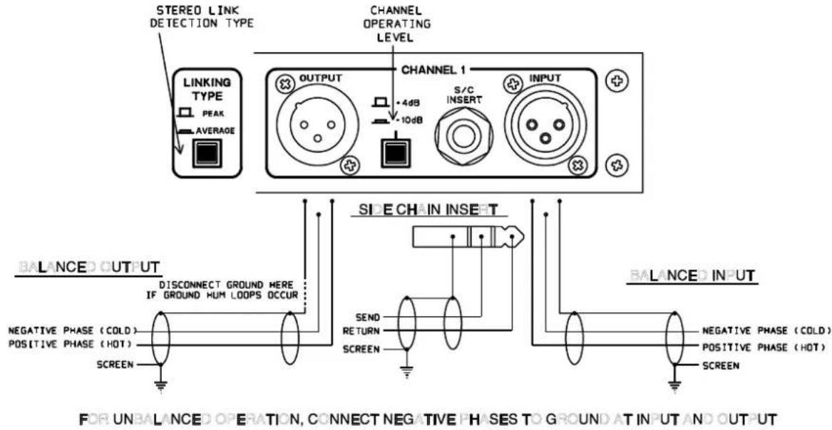
PEAK / AVERAGE LINKING near cpanel cswitch cgives ca cchoice cof ctwo clinking characteristics cwhich conly capply cwhen cthe cunit cis cswitched cfor cstereo clinked operation: Peak or Average. In Peak mode, the gain control of both channels is derived cfrom cthe cpeak clevel cof cwhichever channel is currently cloudest, cwhile cin Average mode, the control signal is derived from the average of the two channel levels. Most users have a preference for one or other mode of operation so once this switch is set, it is unlikely to be changed again.
POWER CONNECTION
The unit will have been supplied with a power cable suitable for domestic power outlets in your country. For your own safety it is important that you use this cable. The unit should always be connected to the mains supply earth using this cable.
If for some reason the unit is to be used at a mains input operating voltage which is different to that as supplied, the following procedure must be carried out. following diagram)
1:cDisconnect the unit from the mains.
2:cUsing ca cnumber c1 csize cpozidrive cscrewdriver, cremove cthe ctwo self-tapping screws holding the voltage selection switch cover plate on the rear panel.
3:cRemove the cover plate and slide the switch fully to its opposite end.
4:cRotate the cover plate one half turn, (180 °) and refit the two screws.
5:cReplace with a correctly rated fuse for the selected operation voltage.
6:cRe-connect to mains power source.
CONTROL DESCRIPTION
Both channels of the DL251 are identical and may be used completely independently or linked for stereo operation. In the linked mode, only the left hand channel controls are functional and serve as master controls while both the compressor/limiters, and the peak limiters of the two channels track together.
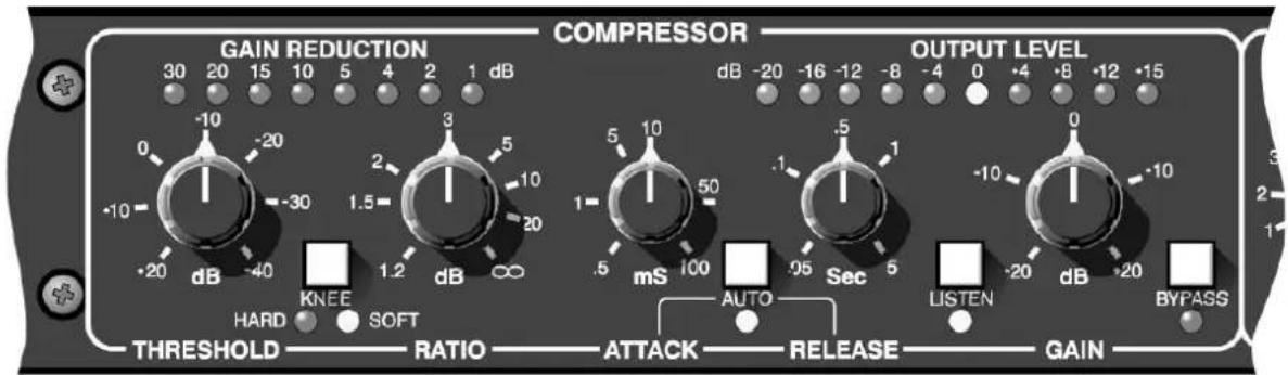
COMPRESSOR
Threshold:
Determines the input level above which gain reduction will be applied and may be set in the range -40 to +20dB. In the 'Soft' mode, the onset of compression is progressive over a nominal range of 10dB, while in 'Hard' mode, gain reduction is applied as soon as the threshold is reached.
Hard/Soft-Knee:
This switches between conventional ratio and soft-knee characteristics. A red status LED indicates hard-knee operation with a yellow LED indicating soft-knee operation.
Ratio:
Sets the compression ratio in the range 1:1 to infinity:1 allowing the possibility of true hard limiting as well as compression. In soft-knee mode, the ratio increases progressively around the threshold cpoint cto ca cmaximum cof cthe cvalue cset cby cthe cRatio control.
Gain Reduction:
A nine segment LED bargraph meter continuously monitors the gain reduction applied by the compressor/limiter over the range 0 to 30dB.
Attack: cSets cthe
crate at cwhich cthe ccompressor cwill crespond cto cinput signals that exceed the threshold level. This may be set in the range 0.5mS to 100mS.
Release: cSets the
rate at which the system gain returns to normal after the input signal level has fallen below the threshold. Adjustment ranges from 50mS to 5 Sec.
Auto: cWhen selec
ted, Auto disables the Attack and Release controls and continually optimises the attack and release times to suit the dynamics cof cthe cmaterial cbeing cprocessed. cln cgeneral, cthis setting will produce the least obtrusive level control on signals with widely varying dynamics such as complete mixes.
S/C Listen: cThis facility allows the user to listen to the side-chain signal. This
is useful if an external processor, such as an equaliser, has been connected via the rear panel insert socket. When this switch is active, the post-insert S/C signal is routed directly to the output of the DL251.
Gain: cThe output level may be attenuated or amplified by up to 20dB
to compensate for level changes caused by compression and limiting. This control comes before the Peak limiter detector and will, as a consequence, influence the limiter action.
Bypass: cThe DL251 features a 'hard bypass' which directly links the input
sockets to the outputs when Bypass is active. The adjacent red LED indicates the Bypass status.
Output Meter:
A 10-segment LED bargraph level meter monitors the level of the output signal over the range -20dB to +15dB with reference to the selected (-10dBV or +4dBu) operating level.
DYNAMIC SPECTRAL ENHANCEMENT
Enhance: cSignals exceeding the compression threshold are dynamically
enhanced to prevent transient detail being compromised when powerful, clow cfrequency csounds coccurring cat cthe csame ctime cause the compressor to apply gain reduction. A typical example is a hi-hat sound occurring at the same time as a bass drum beat; as the compressor pulls down the gain in response to the bass drum level, the hi-hat will be reduced in level by a corresponding amount. A switch marked 'On' with a yellow status LED switches the Enhance system in and out of circuit for A/B checking.
The cDL251 ccontains advanced ccircuitry cwhich cdynamically controls cthe cphase cand cspectral ccontent cof cthe cprogramme material to lift transient detail during times when compression is applied, and the degree of processing is related to the amount of gain reduction taking place. The green LED above the Enhance control cshows cthe cdegree cof enhancement ctaking cplace, cand turning cthe ccontrol cclockwise cwill cincrease cthe camount cof processed signal added to the programme material. With the enhance control rotated fully clockwise and dynamic programme material the green LED will apparently be illuminated constantly, but cthis cis cnot cthe ccase, cdynamic enhancement cwill cstill cbe occurring, only the peaks are now so close together that the human eye cannot detect the frequency.

The Enhance control comes before the Peak Limiter in the signal side chain, therefore more Enhance can cause more Limiting.
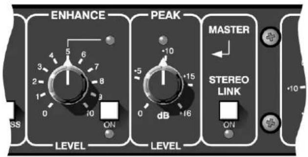
PEAK LIMITER
Level:
This control sets an absolute limit that the output signal may not exceed. This limiter is very fast acting enabling it to control any peaks without audible distortion. If the output signal is so high as to cause the limiter to operate for more than 20mS system gain is automatically reduced to bring the signal back within range. The system gain is then returned to normal over a period cof capproximately cone csecond. cThe ccompressor cGain control should be used to ensure that the peak limiter operates only coccasionally cif cthe limiter is to be used purely for cpeak protection. cAlternatively, cit cmay cbe cdeliberately cdriven cinto limiting to produce creative effects.
STEREO
Stereo Link:
This cswitch cconfigures cthe cchannels cfor cprocessing cstereo programme material where the left hand channel's controls act as master for both audio channels. Linking applies to all switch and knob functions without exception including Bypass and S/C Listen. Only the output level meters remain independent.
The csame cdegree cof cgain creduction cis capplied cto cboth caudio channels to prevent image shifting which would otherwise occur whenever the left and right signal dynamics varied from each other by any significant degree. If the rear panel Link button is set to Peak, then the gain reduction is controlled by the peak level of whichever channel is loudest at any time. In the Average position, the compressor always works from an average of the two channel signals regardless of their relative levels.

The operation of the Stereo Link with the rear panel detection switch set to Peak will be most unpredictable when one channel is operating at +4dB and the other at -10dB. The signal on the channel set to -10dB will most likely control the stereo side chain all of the time.
SIDE CHAIN INSERT
The stereo 14 " jack socket offers the option to insert other external signal processing into the control side chain. The jack socket is configured as the Ring contact being signal send and the Tip contact being signal return. The signal at the jack socket is at -6dB (ref +4dB). This level remains constant irrespective of the operating level set by the rear panel switch.
The cmost ccommon cuse cof cthis cconnection cis cto cpatch cin csome cequalisation cfor 'frequency sensitive' compression, normally called de-essing. The standard method is to insert some boost of the obtrusive frequencies so the compressor side chain 'sees' cmore cof cthese cfrequencies cand capplies cmore compression than cwould cbe normally capplied. cThe cuse cof cthis cfacality cextensive enhancement ccould cbe counter productive, so some moderation is advised.

If the side chain jack socket is permanently wired into a patch bay, it must be connected to a fully normalised pair of sockets. Any poor wire terminations or jack socket closing contacts in the side chain jack wiring will certainly cause some distortion, and may totally prevent compression from happening.
OPERATION
The unit should be connected in-line with the signal to be processed via suitable insert points. Ensure that the insert send and return level on your console matches the operating level set up using the push-buttons on the rear panel of the DL251. If not, select the appropriate operating level on the DL251.
For mono use, each channel may be considered as being completely independent and cset cup caccordingly. cFor cuse cwith cstereo csignals csuch cas ccomplete cmixes cc submixes, the unit should be switched to Stereo Link mode and all setting up done using the left hand channel's controls. The choice of Peak or Average linking is down to user preference and must be selected via the rear-panel switch.
Initial csetting cup cis cbest caccomplished cwith cthe cpeak climiter cthreshold cset cto maximum. cThis callows cthe ccompressor/limiter cto cbe cset cup cin cisolation. cVery generally, the 'hard' ratio setting provides the most positive means of controlling gain and is invariably the preferred choice if the compressor is to be used creatively. Examples include the treatment of individual drum or guitar sounds, or for making rock vocals 'sound' compressed.
The c'Soft' csetting, con cthe cother chand, cis coften cmost ceffective cin ccontrolling cthe dynamics cof ca ccomplex csignal cwhere cunobtrusive ccontrol cis crequired. cTypical applications include complete mixes or submixes, vocals where a natural sound is to be maintained, and instruments that need to retain their original character.
The ratio setting depends on how firmly the signal dynamics need controlling; as a rule, higher ratios provide a higher degree of control but also tend to be more audible in operation when high levels of gain reduction are required, especially when the 'Hard' setting is selected. The integral soft-knee feature of the DL251 renders these effects far less pronounced, but this factor should still be taken into consideration when setting up. In general, when 'Soft' is selected, a higher compression ratio may be used without compromising the sound quality.
If the Attack and Release controls are switched to Auto, setting up is simply a matter of adjusting the Threshold control until the desired amount of gain reduction occurs. This is judged partly by ear and partly by observing the gain reduction Typically, a maximum gain reduction of between 8dB and 12dB will be adequate. If more gain reduction appears necessary, it is safer to apply a conservative degree of compression during recording and then further compression while mixing.
Compression will increase the subjective level of tape and other background noises during pauses and quiet passages because the maximum gain condition occurs when the input signal is at its lowest level. Consequently, the input signal should always be as noise-free as possible and the amount of gain reduction applied should never be more than is necessary. If the compressor is set up so that the gain reduction meter is, for example, reading 10dB during signal peaks, the signal-to-noise ratio during quiet passages or pauses will be degraded by 10dB.
The Auto control may be switched off if it is desired to set the attack and release times manually. The clonger the attack time, cthe longer the ccompressor takes to respond to increases in signal level and a slow attack time is often used to accentuate the beginning of percussive or plucked sounds such as drums, basses and guitars.
A cfast cattack ctime cwill bring the input signal under control very quickly. Effects created by lengthening the attack time are more pronounced when the DL251 is set for 'Hard' compression.
In normal use, the release time should be set short enough so that the system gain has returned to normal before the next peak occurs and, in general, it should be set as short as possible before audible gain 'pumping' occurs.
Set the Gain control to give the required output level using the level meter to guide you. Avoid running at very high output levels as this reduces the available amount of signal headroom and could lead to distortion in extreme cases. Once the gain is correct, set the Peak limiter Level control so that the limiter LED only lights briefly on extreme signal peaks. Alternatively, set the Peak limiter Level to the desired value and then adjust the compressor Gain control to ensure minimum limiter activity.
Compression is often accused of dulling the sound being processed, and a little explanation is needed to understand exactly why that is. What happens is that bass sounds, which contain most of the energy in a typical piece of music, cause the compressor to operate, and so any quieter, high frequency sounds occurring at the same ctime cas cthe cbass csound cwill also be turned down in level. That's why the cymbals cand chi-hats cin ca cheavily ccompressed cdrum ctrack cseem cto cdip cin clevel whenever a loud bass drum or snare drum beat occurs.
A partial solution is either to use less compression or increase the attack time to allow the leading edge of the brighter sounds to pass through the compressor before the gain reduction occurs. However, the DL251's Dynamic Spectral Enhancement feature is designed to prevent the above side-effect by applying dynamic boost to a selective part of the audio spectrum during the period of compression. Once the compressor has been set up normally, the Enhance control setting may be increased as desired.
The Peak limiter has no bypass control, but turning the Level control fully clockwise will prevent any unwanted limiter action. Conversely, by selecting a compression ratio of 1:1, the limiter may be used on its own.
CREATIVE APPLICATIONS
The Enhance control may also be used to create special effects by deliberately over-enhancing cthe ctransient cdetail cof ca csignal. cBecause cthe Dynamic Spectral Enhancement system is dynamically related to the amount of gain reduction taking place, it is necessary to set up the compressor accordingly. Selecting a long decay time will help maintain a high average level of gain reduction while not interfering with the short-term dynamic detail of the signal.
Typical examples include adding extra brightness to steel-strung acoustic guitars or electromechanical pianos, but the applications are limitless and may be extended to cover all manner of synthesised and sampled sounds, percussion and vocals. On a cautionary note, when treating vocals, check that the emphasising any natural sibilance inherent in the sound.
PEAK LINKING
When cthe cDL251 cis cbeing cused cto ccompress cactors' cvoices calong cwith ca cstereo soundtrack, it would be common practice to have a fully-stereo low-level music 'pad' and the louder speech parts panned appropriately to match the visual image. In this configuration Peak type Linking should deal with the programme correctly, without any stereo sound shifting.
SIDE CHAIN INSERT
By patching an equaliser into the side-chain insert point, the compressor can be made to operate in a frequency-selective manner. The S/C Listen switch enables the user to monitor the effect of the equaliser and, because of the compressor action, signals that are most predominant in the equalised sound will cause the greatest degree of gain reduction. This is commonly exploited in de-essing where cvocal sibilance in the range 5kHz to 10kHz can cause problems. By adding, say, a 10dB boost centred at 7kHz, the sibilant sounds fed to the side-chain will be emphasised and, as a consequence, greater gain reduction will be implemented whenever any sibilance occurs.
IF A FAULT DEVELOPS
For warranty service please call Drawmer Electronics Ltd. Or their nearest authorised service facility, giving full details of the difficulty. On receipt of this information, service or shipping instructions will be forwarded to you. No equipment should be returned under the warranty without prior consent from Drawmer or their authorised representative.
For service claims under the warranty agreement a service Returns Authorisation (RA) number will be given. Write this RA number in large letters in a prominent position on the shipping box. Enclose your name, address, telephone number, copy of the original sales invoice and a detailed description of the problem.
Authorised returns should be prepaid and must be insured. All Drawmer products are packaged in specially designed containers for protection. If the unit is to be returned, the coriginal ccontainer cmust cbe cused. clf cthis ccontainer cis cnot cavailable, cthen cthe equipment cshould cbe cpackaged cin csubstantial cshock-proof cmaterial, ccapable cof withstanding the handling for the transit.
CONTACTING DRAWMER
Drawmer Electronics Ltd., will be pleased to answer all application questions to enhance your usage of this equipment. Please address correspondence to:
Drawmer (Technical Help line) : Coleman St.: Parkgate : Rotherham : S62 6EL : UK
or, E-mail us on : ctech@drawmer.co.uk
Drawmer dealers, Authorised service departments and other contact information can be obtained from our web pages on chttp://www.drawmer.co.uk
TECHNICAL SPECIFICATIONS
| INPUT IMPEDANCE | 22KOhm |
| MAXIMUM INPUT LEVEL | +21dBu (+17dB ref. +4dBu) |
| OUTPUT IMPEDANCE | 50 Ohm |
| MAXIMUM OUTPUT LEVEL | +20dBu |
| BANDWIDTH | <12Hz to 25KHz -1dB |
| CROSSTALK | @10kHzcBetter than -80dB@20kHzcBetter than -70dB |
NOISE AT UNITY GAIN reference +4dBu
| Widebandc | 22Hz - 22KHzCCIR | ARMcIEC AcQ-Pk CCIR | ||
| AVc-88 | dBc-94dBc-95 | dBc-98dBc-84dB | ||
| RMSc-8 | 6dBc-92dBc-93 | dBc-96dB |
DISTORTION (No Compression & Enhance Off)
| 100Hzc 1KHz | 10KHz | ||
| Unity Gain, +4dBu Input | < 0.09% | < 0.03% | < 0.08% |
| +14dBu Input, 10dB G.R. | < 0.15% | < 0.15% | < 0.15% |
| POWER REQUIREMENTS | 115Volt or 230Volt at 50-60Hz, 10 Watts |
| FUSE RATING | 50mA for 230Volt, 100mA for 115Volt CONFORMING TO BS EN 60127-2:1991 SHEETIII |
| FUSE TYPE | 20mm x 5mm, Class 3 Slo-Blo, 250Volt working |
| CASE SIZE | 482mm (w) x 44mm (h) x 200mm (d) |
| WEIGHT (incl packaging) | 3.4 Kgs |
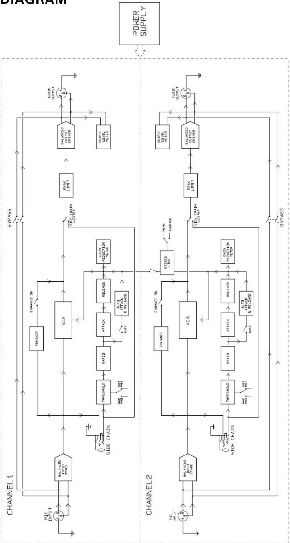
BLOCK DIAGRAM
flowchart
graph TD
    subgraph CHANNEL1
        A["Input"] --> B["BALANCED INPUT STAGE"]
        B --> C["VCA"]
        C --> D["PEAK LIMIT"]
        D --> E["BALANCED OUTPUT DRIVER"]
        E --> F["OUTPUT LEVEL METER"]
        F --> G["AUDIO OUTPUT"]
        H["MIC INPUT"] --> B
        I["SIDE CHAIN"] --> J["THRESHOLD"]
        J --> K["RATIO"]
        K --> L["ATTACK"]
        L --> M["RELEASE"]
        M --> N["GAIN REDUCTION METER"]
        O["SIDE CHAIN LISTEN"] --> P["AUTO ATTACK & RELEASE"]
        Q["HARD KNEE"] --> J
        R["SOFT KNEE"] --> J
        S["AVIO"] --> M
        T["AVIO"] --> N
    end

    subgraph CHANNEL2
        U["Input"] --> V["BALANCED INPUT STAGE"]
        V --> W["VCA"]
        W --> X["PEAK LIMIT"]
        X --> Y["BALANCED OUTPUT DRIVER"]
        Y --> Z["AUDIO OUTPUT"]
        AA["SIDE CHAIN"] --> AB["THRESHOLD"]
        AB --> AC["RATIO"]
        AC --> AD["ATTACK"]
        AD --> AE["RELEASE"]
        AE --> AF["GAIN REDUCTION METER"]
        AG["HARD KNEE"] --> AC
        AH["SOFT KNEE"] --> AC
        AI["AVIO"] --> AF
        AJ["AUTO ATTACK & RELEASE"] --> AC
    end

    B --> C
    C --> D
    D --> E
    E --> F
    F --> G
    G --> H
    H --> I
    I --> J
    J --> K
    K --> L
    L --> M
    M --> N
    N --> O
    O --> P
    P --> Q
    Q --> R
    R --> S
    S --> T
    T --> U
    U --> V
    V --> W
    W --> X
    X --> Y
    Y --> Z
    Z --> AA
    AA --> AB
    AB --> AC
    AC --> AD
    AD --> AE
    AE --> AF
    AF --> AG
    AG --> AH
    AH --> AI
    AI --> AJ
    AJ --> AK["POWER SUPPLY"]