LA12 - Botmixer DRAWMER - Ingyenes használati útmutató
Találja meg az eszköz kézikönyvét ingyenesen LA12 DRAWMER PDF formátumban.

Felhasználói kérdések a következőről LA12 DRAWMER
0 kérdés erről a készülékről. Válaszolj azokra, amiket ismersz, vagy tedd fel a sajátod.
Tegyél fel egy új kérdést erről a készülékről
Töltse le az útmutatót a következőhöz Botmixer PDF formátumban ingyenesen! Találja meg kézikönyvét LA12 - DRAWMER és vegye vissza elektronikus eszközét a kezébe. Ezen az oldalon közzé van téve az eszköze használatához szükséges összes dokumentum. LA12 márka DRAWMER.
HASZNÁLATI ÚTMUTATÓ LA12 DRAWMER
DRAWMER
LA12
LINE AMP
OPERATORS MANUAL
CONTENTS
SAFETY CONSIDERATIONSHpage 1
INSTALLATIONHpage 2
INTRODUCTIONHpage 3
OPERATIONHpage 3
FRONT & REAR PANEL LAYOUTpage 4
IF A FAULT DEVELOPSHpage 5
CONTACTING DRAWMERHpage 5
TECHNICAL SPECIFICATIONHpage 5
BLOCK DIAGRAMHpage 6
COPYRIGHT
This manual is copyrighted © 1997 by Drawmer Electronics, Ltd. With all rights reserved. Under copyright laws, this manual may not be duplicated in whole or in part without the written consent of Drawmer.
ONE YEAR LIMITED WARRANTY
Drawmer Electronics Ltd., warrants the Drawmer LA12 audio processor to conform substantially to the specifications of this manual for a period of one year from the original date of purchase when used in accordance with the specifications detailed in this manual. In the case of a valid warranty claim, your sole and exclusive remedy and Drawmer's entire liability under any theory of liability will be to, at Drawmer's discretion, repair or replace the product without charge, or, if not possible, to refund the purchase price to you. This warranty is not transferable. It applies only to the original purchaser of the product.
For warranty service please call your local Drawmer dealer. Alternatively call Drawmer Electronics Ltd. at +44 (0)1709 527574. Then ship the defective product, with transportation and insurance charges pre-paid, to Drawmer Electronics Ltd., Coleman Street, Parkgate, Rotherham, S62 6EL UK. Write the RA number in large letters in a prominent position on the shipping box. Enclose your name, address, telephone number, copy of the original sales invoice and a detailed description of the problem. Drawmer will not accept responsibility for loss or damage during transit.
This warranty is void if the product has been damaged by misuse, modification or unauthorised repair.
THIS WARRANTY IS IN LIEU OF ALL WARRANTIES, WHETHER ORAL OR WRITTEN, EXPRESSED, HIMPLIED HOR HSTATUTORY. HDRAWMER H HMAKES HNO HOTHER WARRANTY EITHER EXPRESS OR IMPLIED, INCLUDING, WITHOUT LIMITATION, ANY IMPLIED WARRANTIES OF MERCHANTABILITY, FITNESS FOR A PARTICULAR PURPOSE, HOR HNON-INFRINGEMENT. HPURCHASER'S HSOLE HAND HEXCLUSIVE REMEDY UNDER THIS WARRANTY SHALL BE REPAIR OR REPLACEMENT AS SPECIFIED HEREIN.
IN NO EVENT WILL DRAWMER ELECTRONICS LTD. BE LIABLE FOR ANY DIRECT, INDIRECT, SPECIAL, INCIDENTAL OR CONSEQUENTIAL DAMAGES RESULTING FROM ANY DEFECT IN THE PRODUCT, INCLUDING LOST PROFITS, DAMAGE TO PROPERTY, HAND, HTO HTHE HEXTENT HPERMITTED HBY HLAW, HDAMAGE HFOR PERSONAL INJURY, EVEN IF DRAWMER HAS BEEN AD POSSIBILITY OF SUCH DAMAGES.
Some Hstates Hand Hspecific Hcountries Hdo Hnot Hallow Hthe Hexclusion Hof Himplied warranties or limitations on how long an implied warranty may last, so the above limitations may not apply to you. This warranty gives you specific legal rights. You may have additional rights that vary from state to state, and country to country.
In the interests of product development, Drawmer reserve the right to modify or improve specifications of this product at any time, without prior notice.
DRAWMER LA12
LINE DISTRIBUTION AMPLIFIER
SAFETY CONSIDERATIONS

CAUTION - MAINS FUSE
TO REDUCE THE RISK OF FIRE REPLACE THE MAINS FUSE ONLY WITH
THE SAME TYPE, WHICH MUST BE A CLASS 3, 230 VOLT, TIME DELAY
TYPE, RATED AT 32mA WHERE THE MAINS INPUT VOLTAGE SWITCH IS SET TO 230 VOLTS AC. AND 63mA WHERE THE MAINS INPUT VOLTAGE
IS 115 VOLTS AC. ALL FUSES MUST COMPLY WITH BS EN 60127-2:1991,
SHEET III. THE FUSE BODY SIZE IS 20mm x 5mm.
CAUTION - MAINS CABLE
DO NOT ATTEMPT TO CHANGE OR TAMPER WITH THE SUPPLIED MAINS CABLE.
CAUTION - SERVICING
DO NOT PERFORM ANY SERVICING. REFER ALL SERVICING TO QUALIFIED SERVICE PERSONNEL.
WARNING
TO REDUCE THE RISK OF FIRE OR ELECTRIC SHOCK DO NOT EXPOSE THIS EQUIPMENT TO RAIN OR MOISTURE.


INSTALLATION
The LA12 is designed for standard 19" rack mounting and occupies 1U of rack space. Avoid mounting the unit directly above power amplifiers or power supplies that radiate significant amounts of heat. Fibre or plastic washers may be used to prevent the front panel becoming marked by the mounting bolts.
AUDIO CONNECTIONS
All audio connections are on professional quality phono (RCA jack) connectors, with white for Left and red for Right channels.
Interference: If the unit is to be used where it may be exposed to high levels of disturbance such as found close to a TV or radio transmitter, we advise that various wiring configurations of different ground points are tried for the lowest noise. The LA12 conforms to the EMC standards.
Ground Loops: If ground loop problems are encountered, never disconnect the mains earth, but instead, try disconnecting the signal screen on one end of each of the cables connecting the outputs of the LA12 to the patchbay.
POWER CONNECTION
The LA12 is supplied with a power cable suitable for domestic power outlets in your country. For your own safety it is important that you use this cable to connect to the mains supply earth. The cable should not be tampered with or modified.
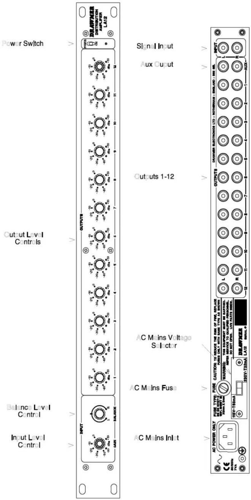
If, for some reason, the unit is to be used at a mains input operating voltage which is different to that as supplied, the following procedure must be carried out (see Front & Rear Panel diagram, on page 4)
1: Disconnect the unit from the mains.
2: Using a number 1 size pozidrive screwdriver, remove the two self-tapping screws holding the voltage selection switch cover plate on the rear panel.
3: Remove the cover plate and slide the switch fully to its opposite end.
4: Rotate the cover plate one half turn, (180 °) and refit the two screws.
5: Replace with a correctly rated fuse for the selected operation voltage.
6: Re-connect to mains power source.
INTRODUCTION
The Drawmer LA12 is a low noise, low crosstalk distribution amplifier. The unit provides one stereo input with master 'gain' and 'balance' controls and twelve stereo outputs, each with individual output level control. It may be used to distribute one stereo signal to up to twelve different outputs. A typical application example would be for real time cassette duplication, but it may be used for a variety of applications, such as the distribution of one stereo signal to other rooms/areas within a complex e.g. discotheques, shopping malls etc.
A maximum gain of +20dB is available through the unit, which allows a wide range of 'source' and 'destination' equipment to be interfaced.
An auxiliary stereo output which follows the input gain and balance controls can be linked to the input of a second LA12 if further stereo outputs are required.
For very long signal lines, and where balanced, or isolated, operation is required, Drawmer also can offer the DA6, which higher specification unit to the LA12
OPERATION
The LA12 has been designed for ease of use. It operates on input levels in the range -10dB to +10dB. The signal source should be connected to the rear panel sockets marked 'INPUT' Left & Right, and the 'OUTPUT' sockets should be similar connected to their appropriate destinations. Each of the front panel controls adjust both Left and Right channels.
INPUT:
The Input Level is determined by rotation of the 'Gain' control. 'Balance' control adjusts the stereo balance between Left and Right channels.
OUTPUT:
The 'Output' controls, numbered 1 to 12, adjust the level at the corresponding output phono connector pair on the rear panel.
AUXILIARY OUTPUT:
This output phono connector pair can be used to link to another LA12. The level of the auxil determined by INPUT GAIN and BALANCE controls.
FRONT & REAR PANEL LAYOUT
IF A FAULT DEVELOPS
For warranty service please call Drawmer Electronics Ltd. Or their nearest authorised service facility, giving full details of the difficulty. On receipt of this information, service or shipping instructions will be forwarded to you. No equipment should be returned under the warranty without prior consent from Drawmer or their authorised representative.
For service claims under the warranty agreement a service Returns Authorisation (RA) number will be given. Write this RA number in large letters in a prominent position on the shipping box. Enclose your name, address, telephone number, copy of the original sales invoice and a detailed description of the problem.
Authorised returns should be prepaid and must be insured. All Drawmer products are packaged in specially designed containers for protection. If the unit is to be returned, the original container must be used. If this container is not available, then the equipment Hshould Hbe Hpackaged Hin Hsubstantial Hshock-proof Hmaterial, Hcapable Ho withstanding the handling for the transit.
CONTACTING DRAWMER
Drawmer Electronics Ltd., will be pleased to answer all application questions to enhance your usage of this equipment. Please address correspondence to:
Drawmer (Technical Help line) : Coleman St.: Parkgate : Rotherham : S62 6EL : UK
or, E-mail us on : Htech@drawmer.co.uk
Drawmer dealers, Authorised service departments and other contact information can be obtained from our web pages on Hhttp://www.drawmer.co.uk
TECHNICAL SPECIFICATIONS
| INPUT IMPEDANCE | 22KOhm |
| INPUT GAIN | Max+10dB |
| OUTPUT GAIN | -40dB to +10dB |
| NOISE HBetter than-100dB | |
| (ref +4dBv, Gain=0dB, @ 22Hz - 22KHz) | |
| CROSSTALK | -67dB @ 10KHz |
| (Input grounded, any channel output) | |
| DISTORTION | 0.008% @ 100Hz |
| 0.015% @ 1KHz to 10KHz | |
| BANDWIDTH | 5Hz to 25Khz -1dB |
| POWER REQUIREMENTS | 115Volt or 230Volt at 50-60Hz, 7 Watts |
| FUSE RATING | 32mA for 230Volt, 63mA for 115Volt CONFORMING TO BS EN 60127-2:1991 SHEET III |
| FUSE TYPE | 20mm x 5mm, Class 3 Slo-Blo, 250Volt Working |
| CASE SIZE | 482mm (w) x 44mm (h) x 200mm (d) |
| WEIGHT (incl packaging)H3.4 Kgs | |
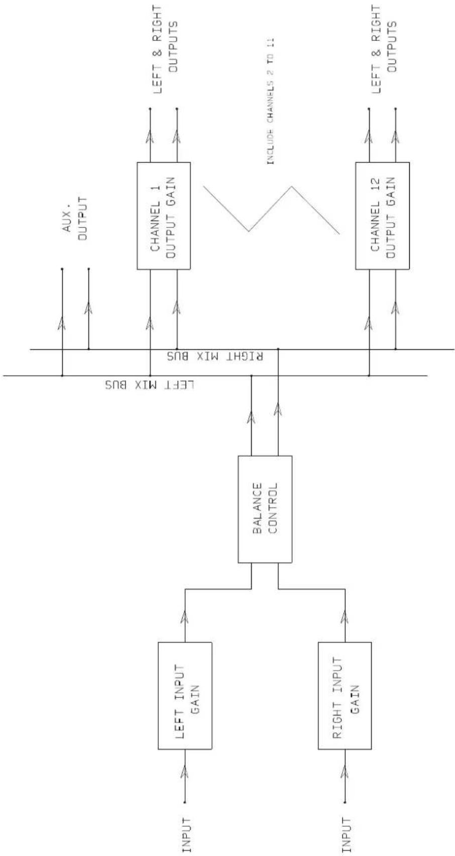
BLOCK DIAGRAM
flowchart
graph LR
    A["INPUT"] --> B["LEFT INPUT GAIN"]
    C["INPUT"] --> D["RIGHT INPUT GAIN"]
    B --> E["BALANCE CONTROL"]
    D --> E
    E --> F["AUX. OUTPUT"]
    E --> G["RIGHT MIX BUS"]
    G --> H["CHANNEL 1 OUTPUT GAIN"]
    H --> I["LEFT & RIGHT OUTPUTS"]
    E --> J["RIGHT MIX BUS"]
    J --> K["CHANNEL 12 OUTPUT GAIN"]
    K --> L["LEFT & RIGHT OUTPUTS"]
    M["INCLUDE CHANNELS 2 TO 11"] --> K