GT 125 (2003) - Robogó VESPA - Ingyenes használati útmutató
Találja meg az eszköz kézikönyvét ingyenesen GT 125 (2003) VESPA PDF formátumban.

Felhasználói kérdések a következőről GT 125 (2003) VESPA
0 kérdés erről a készülékről. Válaszolj azokra, amiket ismersz, vagy tedd fel a sajátod.
Tegyél fel egy új kérdést erről a készülékről
Töltse le az útmutatót a következőhöz Robogó PDF formátumban ingyenesen! Találja meg kézikönyvét GT 125 (2003) - VESPA és vegye vissza elektronikus eszközét a kezébe. Ezen az oldalon közzé van téve az eszköze használatához szükséges összes dokumentum. GT 125 (2003) márka VESPA.
HASZNÁLATI ÚTMUTATÓ GT 125 (2003) VESPA
WORKSHOP MANUAL
633338
natural_image
Side view of a modern silver scooter with visible wheels and front side (no text or symbols)Vespa GT 125-200

WORKSHOP MANUAL
Vespa GT 125-200
The descriptions and illustrations supplied in this publication are not binding. PIAGGIO therefore reserves the right to make any changes to pieces, parts or accessory supplies, which it believes to be appropriate for improvement purposes or any requirement of a constructive or commercial nature, at any time, without the obligation to up-dating this publication before time, the essential characteristics of the type described and illustrated here remaining valid.
Not all versions reported in this publication are available in all Countries. The availability of single versions should be checked at the official Piaggio sales network.
"© Copyright 2003 - PIAGGIO & C. S.p.A. Pontedera. All rights reserved. No part of this publication may be reproduced."
PIAGGIO & C. S.p.A. - After Sales Service
www.piaggio.com
V.le R. Piaggio, 23 - 56025 PONTEDERA (Pi)
WORKSHOPBMANUAL
VespaBGTB125-200
This, workshop, manual, has been drawn, up, by, Piaggio, & C., Spa, to, be, used, by, the workshops, of, Piaggio-Gilera, dealers. This, manual, is addressed, to, Piaggio, service mechanics, who are supposed, to, have a, basic knowledge, of, mechanics, principles and, of, vehicle, fixing, techniques, and, procedures. Any important changes, made, to, the vehicles, or, to, specific, fixing, operations, will, be, promptly, reported, by, updates, to, this manual. Nevertheless, no, fixing, work, can, be, satisfactory, if, the necessary, equipment and tools are unavailable. It is therefore advisable to read the sections of this manual relating to specific tools, along with the specific tool catalogue.
N.B. Provides key information to make the procedure easier to understand and carry out.
CAUTION Refers to specific procedures to carry out for preventing damages to the vehicle.
WARNING Refers to specific procedures to carry out to prevent injuries to the repairer.

Personal safety Failure to completely observe these instructions will result in serious risk of personal injury.

Safeguarding the environment Sections marked with this symbol indicate the correct use of the vehicle to prevent damaging the environment.

Vehicle intactness The incomplete or non-observance of these regulations leads to the risk of serious damage to the vehicle and sometimes even the invalidity of the guarantee.

natural_image
Silver Vespa scooter with black seat and silver body (no visible text or symbols)[Non-Text]
[Non-Text]
[Non-Text]
[Non-Text]
[Non-Text]
[Non-Text]
[Non-Text]
[Non-Text]
[Non-Text]
[Non-Text]
[Non-Text]
[Non-Text]
[Non-Text]
[Non-Text]
[Non-Text]
[Non-Text]
[Non-Text]
[Non-Text]
[Non-Text]
[Non-Text]
[Non-Text]
[Non-Text]
[Non-Text]
[Non-Text]
[Non-Text]
[Non-Text]
[Non-Text]
[Non-Text]
[Non-Text]
[Non-Text]
[Non-Text]
[Non-Text]
[Non-Text]
INDEXBOFBTOPICS
CHARACTERISTICSB
TOOLINGB
MAINTENANCEB
TROUBLESHOOTINGB
ELECTRICALBSYSTEMB
ENGINEBFROMBVEHICLEB
ENGINEB
SUSPENSIONSB
BRAKINGBSYSTEMB
COOLINGBSYSTEMB
CHASSISB
PRE-DELIVERYB
TIMEB
INDEX OF TOPICS
CHARACTERISTICS
This section describes the general characteristics of the vehicle.
Rules
This section describes general safety rules for any interventions to be performed on the vehicle.
Safety rules
- Should it be necessary to keep the engine running while servicing, make sure that the area or room is well ventilated, and use special exhaust fans, if required. Never let the engine running in closed rooms. In fact, exhaust gases are toxic.
- The battery electrolyte contains sulphuric acid. Protect your eyes, cloths and skin. Sulphuric acid is highly corrosive; in the event of contact with your eyes or clothes, rinse thoroughly with water and consult a doctor immediately.
- The battery produces hydrogen, a gas that can be highly explosive. Do not smoke and avoid sparks and flames when close to the battery, especially during recharge.
- Fuel is highly flammable, and in some conditions it can be explosive. Do not smoke in the working area, and avoid free flames or sparks.
- Clean the brake pads in a well ventilated environment, directing the compressed air jet so as to not intake the dust produced by the wear of the friction material. Even though the latter contains no asbestos, dust inhalation is harmful.
Safety rules
- Use original PIAGGIO spare parts and lubricants recommended by the Manufacturer. Non-original or non-conforming spares may damage the vehicle.
- Use only the specific tools designed for this vehicle.
- Always use new gaskets, sealing rings and split pins upon reassembly.
- After removal, clean the components using non-flammable or low fire-point solvent. Lubricate all working surfaces before reassembly, except for conical couplings.
- After reassembly, check that all components have been installed properly and that they are in good working order.
- For removal, overhaul and reassembly operations use only tools provided with metric measures.
Metric bolts, nuts and screws are not interchangeable with coupling members with English measurement. Using improper coupling members and tools may impair the vehicle. - Should any interventions to the vehicle electric system be required, check that the electrical connections - especially earth and battery connections - have been implemented properly.
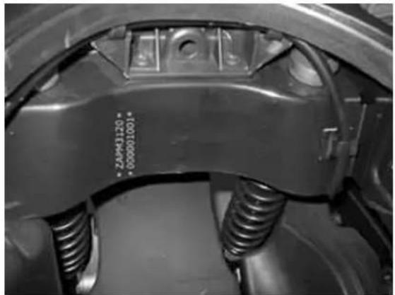
Vehicle identification
Granturismo 125
Chassis prefix: ZAPM311000000 ÷ 1001
Engine prefix: M311M1001
Granturismo 200
Chassis prefix: ZAPM312000000 ÷ 1001
Engine prefix: M312M1001
natural_image
Close-up of a car brake system with springs and calipers (no visible text or symbols)
natural_image
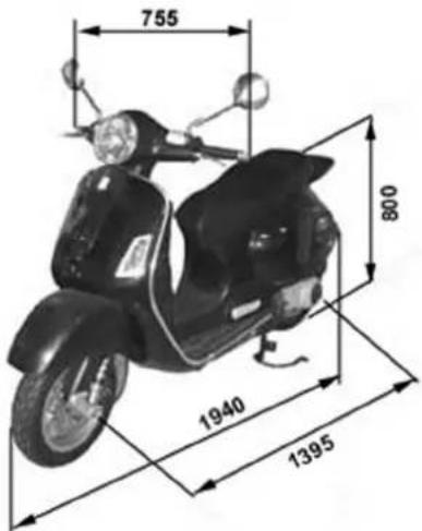
Technical line drawing of a car's seat and dashboard assembly (no text or symbols)Dimensions and mass
MASS AND DIMENSIONS
Specification Desc./Quantity
| Total loadless weight 140 Kg | |
| Width (at the handles) | 755 mm |
| Length 1940 mm | |
| Wheel base 1395 mm | |
| Saddle height 800 mm | |
Engine
DATA 125
Specification Desc./Quantity
| Type | single-cylinder, four-stroke and four valves, fluid-cooled |
| Timing system | single-head camshaft controlled by left side chain, 3-arm rockers with threaded register |
| Bore 125,57 mm | |
| Stroke,48,6 mm | |
| Piston displacement 125,124,015 cm3 | |
| Compression ratio 125 | 12 ÷ 13 : 1 |
| Walbro Carburettor 125,WVF-7G | |
| Keihin Carburettor 125,CVK 30 | |
| Engine idle,1650 ± 50 rpm | |
| CO value,3,8 ± 0,7 % | |
| Air filter | sponge, impregnated with mixture (50% fuel and 50% oil) |
| Start-up system | electric starter motor (engine 200 cc with torque limiter) |
| Lubrication | with twin-screw pump (inside the crankcase) controlled by chain and dual filter: net and paper filter |
| Power supply | fuel, with vacuum pump and by carburettor |
| Max power (shaft) 125 | 11 kW (15 cv) at 9,700 rpm |
| Max speed 125 | 104 Km/h |
DATA 200
Specification Desc./Quantity
| Type | single-cylinder, four-stroke and four valves, fluid-cooled |
| Timing system | single-head camshaft controlled by left side chain, 3-arm rockers with threaded register |
| Bore 200,72 mm | |
| Stroke,48,6 mm | |
| Piston displacement 200,197,775 cm3 | |
| Compression ratio 200 | 11 ÷ 12 : 1 |
| Walbro Carburettor 200,WVF-7P | |
| Keihin Carburettor 200,CVK 30 | |
| Engine idle,1650 ± 50 rpm | |
| CO value,3,8 ± 0,7 % | |
| Air filter | sponge, impregnated with mixture (50% fuel and 50% oil) |
| Start-up system | electric starter motor (engine 200 cc with torque limiter) |
| Lubrication | with twin-screw pump (inside the crankcase) controlled by chain and dual filter: net and paper filter |
| Power supply | fuel, with vacuum pump and by carburettor |
| Max power (shaft) 200 | 15.4 kW (21 cv) at 8,500 rpm |
| Max speed 200 | 125 Km/h |
Transmission
TRANSMISSION
| Specification Desc./Quantity | |
| Transmission | With automatic expandable pulley varistor with servo-system, trapezoidal belt, automatic clutch, gear reducer and transmission compartment cooled with forced air circulation |
Capacities
CAPACITY
| Specification Desc./Quantity | |
| Engine oil | ~ 1,000 cc (recommended oil Selenia HI Scooter 4 Tech) |
| Rear hub | 150 cc (recommended oil TUTELA ZC 90) |
ElectricalBsystem
ELECTRICBCOMPONENTSB125
SpecificationBDesc./Quantity
| Ignition type | Electronic start with capacitive discharge, with variable advance and separate HT coil |
| Variable spark advance (before T.D.C.) 125 | from 10^ ± 1^ to 2,000 rpm at 34^ ± 1^ to 6,000 rpm |
| Spark plug 125 | CHAMPION RG 4 HC |
| Battery,12V/ 12 Ah | |
| Fuses | N° 1 15A, N° 1 10A, N° 3 7,5A, N° 2 5A |
| Generator,in alternating current |
ELECTRICBCOMPONENTSB200
SpecificationBDesc./Quantity
| Ignition type | Electronic start with capacitive discharge, with variable advance and separate HT coil |
| Variable spark advance (before T.D.C.) 200 | from 10^ ± 1^ to 2,000 rpm at 32^ ± 1^ to 6,500 rpm |
| Spark plug 200 | CHAMPION RG 6 YC |
| Battery,12V/ 12 Ah | |
| Fuses | N° 1 15A, N° 1 10A, N° 3 7,5A, N° 2 5A |
| Generator,in alternating current |
FrameBandBsuspensions
CHASSISBANDBSUSPENSIONS
SpecificationBDesc./Quantity
| Type | Structural frame in pressed sheet steel. |
| Front suspension | Single-arm suspension equipped with dual-effect hydraulic shock absorber with coaxial spring |
| Front shock absorber axial stroke | 86,5 mm |
| Rear suspension | Engine based on oscillating fork pivoted to the chassis by 2-freedom degree arm. Pair of dual effect hydraulic shock absorbers and coaxial springs with 3-position preload adjustment |
| Rear shock abs. axial stroke | 89,5 mm |
Brakes
FRONT
SpecificationBDesc./Quantity
| Front | Disc, 220 mm diameter and dual-piston floating caliper ∅ 25 mm with hydraulic control (lever on the handlebar right end) |
| Rear | Disc, 220 mm diameter and two opposed piston caliper ∅ 30 mm with hydraulic control (lever on the handlebar left end). |
WheelsBandBtyres
WHEELSBANDBTYRES
SpecificationBDesc./Quantity
| Front light alloy rims,3,00x12 |
| Rear light alloy rims,3,00x12 |
| Front tyres,120/70-12" Tubeless |
| Rear tyres,130/70-12" Tubeless |
TYRESBPRESSURE
SpecificationBDesc./Quantity
| Front tyres pressure (when cold) | 1,8 bar |
| Rear tyres pressure (when cold) | 2 bar |
| Tyres pressure (when cold): | 2,2 bar (with passenger) |
| N.B. | |
CHECKBANDBADJUSTBTIREBPRESSUREBWITHBTIRESBATBAMBIENTBTEMPERATURE.BADJUSTBPRESSURE ACCORDINGBTOBTHEBWEIGHTBOFBTHEBRIDERBANDBACCESSORIES.
Carburettor
125ccBVersion
Kehin
KEHINBCARBURETTORB125
SpecificationBDesc./Quantity
| Depression type | CVEK 30 |
| Printing on the body | CVEK |
| CUT-OFF device | Not present |
| Max jet | 98 |
| Minimum jet | 38 |
SpecificationBDesc./Quantity
| Max air jet,150 | |
| Minimum air jet,130 | |
| Gas valve spring | 100 ÷ 160 gr |
| Idle mixture adjustment screw initial opening | 2 ± 1/4 |
| Conical pin,NDVA | |
| Conical pin top notches | Single notch pin |
| Emulsifier nozzle,∅ 5,0 | |
| Fuel inlet hole,- | |
| Starter air jet,∅ 1,5 | |
| Starter emulsifier jet,- | |
| Starter jet,42 | |
| Starter pin diameter,- | |
| Starter device resistance | ~ 20 Ω |
| Venturi choke,∅ 29 (47x30,9) | |
| Throttle valve | ∅ 30,5 |
| Choke maximum cone | - |
| N.B. | |
THE IDENTIFICATION LETTER CAN VARY EVERY TIME THE CARBURETTOR IS UPDATED.
Walbro
WALBRO CARBURETTOR 125
SpecificationBDesc./Quantity
| Depression type | WVF-7R* |
| Printing on the body | 7R1 |
| CUT-OFF device | Not. pres. |
| Max jet | 103 |
| Minimum jet | 38 |
| Max air jet | 60 |
| Minimum air jet,110 | |
| Gas valve spring | 100 gr |
| Idle mixture adjustment screw initial opening | 2 7/8 ± 1/2 |
| Conical pin | 653 |
| Conical pin top notches | 2 |
| Emulsifier nozzle,∅ 2,7 |
SpecificationBDesc./Quantity
| Fuel inlet hole,∅ 1,5 | |
| Starter air jet,200 | |
| Starter emulsifier jet,130 | |
| Starter jet,48 | |
| Starter pin diameter,∅ 1,78 | |
| Starter device resistance | ~ 40 Ω |
| Choke,∅ 29 (30,3x27,0) | |
| Throttle valve,∅ 33 | |
| Choke maximum cone,∅ 48,0 | |
| N.B. | |
THEBIDENTIFICATIONBLETTERBCANBVARYBEVERYBTIMEBTHEBCARBURETTORBISBUPDATED.
200ccBVersion
Kehin
KEHINBCARBURETTORB200
| SpecificationBDesc./Quantity | |
| Depression type,CVEK 30 | |
| Printing on the body,CVK | |
| CUT-OFF device,Present | |
| Max jet | 92 |
| Minimum jet | 38 |
| Max air jet | 70 |
| Minimum air jet | 115 |
| Gas valve spring | 0,150 - 0,250 Kgf |
| Idle mixture adjustment screw initial opening | 2 1/4 ± 1/4 |
| Conical pin | NDAA |
| Conical pin top notches | Single notch pin |
| Emulsifier nozzle | ∅ 5,0 |
| Fuel inlet hole | - |
| Starter air jet,∅ 1,5 | |
| Starter emulsifier jet | - |
| Starter jet,42 | |
| Starter pin diameter | - |
SpecificationBDesc./Quantity
Starter device resistance
\~ 20 Ω
Venturi choke, ∅ 29 (47x30,9)
Throttle valve,∅ 30,5
Choke maximum cone,-
N.B.
THEBIDENTIFICATIONBLETTERBCANBVARYBEVERYBTIMEBTHEBCARBURETTORBISBUPDATED.
Walbro
WALBROBCARBURETTORB200
SpecificationBDesc./Quantity
Depression type, WVF-7P*
Printing on the body,7P
CUT-OFF device, Present
Max jet,95
Minimum jet,33
Max air jet,120
Minimum air jet,55
Gas valve spring, 120 gr
Idle mixture adjustment screw initial opening
2 ± 1/2
Conical pin
495
Conical pin top notches
2
Emulsifier nozzle
∅ 2,7
Fuel inlet hole
∅ 1,5
Starter air jet
200
Starter emulsifier jet
110
Starter jet
45
Starter pin diameter
∅ 1,78
Starter device resistance
\~ 40 Ω
Choke
∅ 29 (30,3×27,0)
Throttle valve
∅ 33
Choke maximum cone
∅ 48,0
N.B.
THEBIDENTIFICATIONBLETTERBCANBVARYBEVERYBTIMEBTHEBCARBURETTORBISBUPDATED.
TighteningBTorques
STEERINGBUNIT
NameBTorqueBinBNm
| Steering upper collar | 30 ÷ 40 |
| Steering lower collar,8 ÷ 10 | |
| Handlebar fastening screw | 45 ÷ 50 (The two screws must be tightened after tightening the rear wheel axle nut at the prescribed torque.) |
| Handlebar control unit U-bolts fixing screws | 7 ÷ 10 |
CHASSISBUNIT
NameBTorqueBinBNm
| Oscillating arm pin - engine | 64 ÷ 72 |
| Oscillating arm pin - body | 76 ÷ 83 |
| Engine and vehicle side oscillating arm junction pin | 33 ÷ 41 |
| Silent-block support plate bolt | 42 ÷ 52 |
| Central stand bolt,25 ÷ 30 | |
| Side stand fastening bolt | 40 ÷ 45 |
FRONTBSUSPENSION
NameBTorqueBinBNm
| Screw fixing the shock absorber to the shock absorber plate - brake pliers | 20 ÷ 27 |
| Wheel axle nut,75 ÷ 90 | |
| Wheel screw,20 ÷ 25 | |
| Screw fixing the front mudguard to the steering wheel | 5 ÷ 6,5 |
FRONTBBRAKE
NameBTorqueBinBNm
| Pipe - pump oil union | 20 ÷ 25 |
| Pliers-pipe oil union | 20 ÷ 25 |
| Screw fixing the pliers to the shock absorber plate- brake pliers | 20 ÷ 25 |
| Disc tightening screw | 6 (Apply thread-holding LOCTITE medium type 242.) |
| Oil drainage screw | 12 ÷ 16 |
| Pads fixing pin | 19,6 ÷ 24,5 |
| Brake pump basin screws | 15 ÷ 20 |
REARBSUSPENSION
NameBTorqueBinBNm
| Screw fixing the left shock absorber support plate to the crankcase | 20 ÷ 25 |
| Shock absorber top fixing | 20 ÷ 25 |
| Shock absorber bottom fixing | 33 ÷ 41 |
| Rear wheel axle 104 ÷ 126 | |
| Screws fixing the wheel to the hub | 20 ÷ 25 |
| Silencer - shock absorber support arm screws on engine | 20 ÷ 25 (The two screws must be tightened after tightening the rear wheel axle nut at the prescribed torque.) |
REARBBRAKE
NameBTorqueBinBNm
| Pipe - pump oil union | 20 ÷ 25 |
| Tube-caliper oil connection | 20 ÷ 25 |
| Rear disc tightening bolt | 11 ÷ 13 |
| Oil drainage screw 12 ÷ 16 | |
| Screw fixing the brake caliper to the engine | 20 ÷ 25 |
| Brake pump basin screws | 15 ÷ 20 |
| Caliper coupling screws | 30 ÷ 33 |
SILENCER
NameBTorqueBinBNm
| Silencer heat guard fixing screw | 5 ÷ 6 |
| Exhaust gas inlet screw | 13 ÷ 15 |
| Screw fixing the silencer to the support arm | 20 ÷ 25 |
LUBRICATION
NameBTorqueBinBNm
| Hub oil exhaust cap | 15 ÷ 17 |
| Oil filter union on crankcase | 27 ÷ 33 |
| Engine oil / net filter drainage cap | 24 ÷ 30 |
| Oil filter | 8 ÷ 10 |
| Oil pump cover screws | 7 ÷ 9 |
| Screws fixing the oil pump to the crankcase | 5 ÷ 6 |
| Oil pump control rim screw | 10 ÷ 14 |
| Oil pump cover plate screws | 4 ÷ 6 |
| Oil sump screws | 10 ÷ 14 |
Name Torque in Nm
| Minimum oil pressure sensor | 12 ÷ 14 |
CYLINDER HEAD
Name Torque in Nm
| Spark plug,12 ÷ 14 | |
| Head cover screws,6 ÷ 7 | |
| Nuts fixing the head to the cylinder | 7±1 + 180° (2x90°) (Fasten the nuts in two crossed steps.) (Lubricate the nuts with engine oil before assembly.) |
| Head fastening side screws | 11 ÷ 13 |
| Start up mass screws (200 cc) | 7 ÷ 8,5 |
| Side screw M5 locking the washers on the camshaft (125 cc) | 7 ÷ 8,5 |
| Tappet adjustment lock nut | 6 ÷ 8 |
| Intake manifold screws | 11 ÷ 13 |
| Timing chain tightener sliding block screws | 10 ÷ 14 |
| Start up mass bell screws (200 cc) | 11 ÷ 15 |
| Central screw M6 locking the washers on the camshaft (125 cc) | 11 ÷ 15 |
| Timing belt tightener support screw | 11 ÷ 13 |
| Timing belt tightener central screw | 5 ÷ 6 |
| Camshaft retain plate screw | 4 ÷ 6 |
TRANSMISSION
Name Torque in Nm
| Belt support roller screw | 11 ÷ 13 |
| Clutch unit nut on driven pulley | 55 ÷ 60 |
| Driving pulley nut | 75 ÷ 83 |
| Transmission cover screws | 11 ÷ 13 |
| Driven pulley axis nut | 54 ÷ 60 |
| Rear hub cover screws | 24 ÷ 27 |
FLYWHEEL
Name Torque in Nm
| Flywheel cover fastening screws | 5 ÷ 6 |
| Stator unit screws | 3 ÷ 4 (Apply thread-holding LOCTITE medium type 242.) |
| Flywheel nut | 52 ÷ 58 |
Name Torque in Nm
Pick-Up fixing screws,3 ÷ 4
ENGINE CRANKCASE AND SHAFT
| Name Torque in Nm | |
| Engine crankcase inside head screws(transmission side half shaft) | 4 ÷ 6 |
| Engine crankcase coupling screws | 11 ÷ 13 |
| Starting motor screws | 11 ÷ 13 |
| Crankcase timing cover screws | 3,5 ÷ 4,5 (Apply thread-holding LOCTITE medium type 242.) |
COOLING
| Name Torque in Nm | |
| Water pump impeller cover | 3 ÷ 4 |
| Water pump impeller driving joint screws | 3 ÷ 4 |
| Thermostat cover screws | 3 ÷ 4 |
Overhaul data
Assembly clearances
Cylinder - piston assy.
CATEGORIES COUPLING 125
| Name | Play | Initials | Cylinder | Piston | Play on fitting | ||
| Cylinder | 57 | +0,025 - | A | 56,997 ÷ | 56,945 ÷ | 0,045 - 0,059 | |
Name Play Initials Cylinder Piston Play on fitting
| 0,003,57,004,56,952 | |||||
| Cylinder,57 +0,025 - 0,003 | B,57,004 ÷ 57,011 | 56,952 ÷ 56,959 | 0,045 - 0,059 | ||
| Piston,56,959 ±0,014,C,57,011 ÷ | 56,959 ÷ 56,966 | 0,045 - 0,059 | |||
| Piston,56,959 ±0,014,D,57,018 ÷ | 56,966 ÷ 56,973 | 0,045 - 0,059 | |||
| Cylinder first uprat. | 57,2 +0,025 - 0,003 | A 1,57,197 ÷ 57,204 | 57,145 ÷ 57,152 | 0,045 - 0,059 | |
| Cylinder first uprat. | 57,2 +0,025 - 0,003 | B 1,57,204 ÷ 57,211 | 57,152 ÷ 57,159 | 0,045 - 0,059 | |
| Piston first uprat. | 57,159 ±0,014,C 1,57,211 ÷ | 57,159 ÷ 57,166 | valore | ||
| Piston first uprat. | 57,159 ±0,014,D 1,57,218 ÷ | 57,166 ÷ 57,173 | valore | ||
| Cylinder second uprat. | 57,4 +0,025 - 0,003 | A 2,57,397 ÷ 57,404 | 57,345 ÷ 57,352 | 0,045 - 0,059 | |
| Cylinder second uprat. | 57,4 +0,025 - 0,003 | B 2,57,404 ÷ 57,411 | 57,352 ÷ 57,359 | 0,045 - 0,059 | |
| Piston second uprat. | 57,359 ±0,014,C 2,57,411 ÷ | 57,411 ÷ 57,418 | 0,045 - 0,059 | ||
| Piston second uprat. | 57,359 ±0,014,D 2,57,418 ÷ | 57,366 ÷ 57,373 | 0,045 - 0,059 | ||
| Cylinder third uprat. | 57,6 +0,025 - 0,003 | A 3,57,597 ÷ 57,604 | 57,545 ÷ 57,552 | 0,045 - 0,059 | |
| Cylinder third uprat. | 57,6 +0,025 - 0,003 | B 3,57,604 ÷ 57,611 | 57,552 ÷ 57,559 | 0,045 - 0,059 | |
| Piston third uprat. | 57,559 ±0,014 | 3C | 57,611 ÷ 57,618 | 57,559 ÷ 57,566 | 0,045 - 0,059 |
| Piston third uprat. | 57,559 ±0,014,D 3,57,618 ÷ | 57,566 ÷ 57,573 | 0,045 - 0,059 | ||
CATEGORIES COUPLING 200
Name Play Initials Cylinder Piston Play on fitting
| Cylinder,72 +0,018 - 0,010 | B,71,997 ÷ 72,004 | 71,960 ÷ 71,967 | 0,030 - 0,044 |
| Cylinder,72 +0,018 - 0,010 | A,71,990 ÷ 71,997 | 71,953 ÷ 71,960 | 0,030 - 0,044 |
| Piston,71,967 ±0,014,D,72,011 ÷ 72,018 | 71,974 ÷ 71,981 | 0,030 - 0,044 | |
| Piston,71,967 ±0,014,C,72,004 ÷ 72,011 | 71,967 ÷ 71,974 | 0,030 - 0,044 |
Crankcase - crankshaft - connecting rod
DRIVING SHAFT
Axial clearance between engine and connecting rod
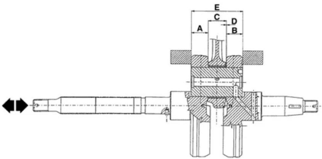
CRANKSHAFT-CRANKCASE AXIAL CLEARANCE /CARTER
Name Description Dimensions Initials Quantity
| Half shaft trans-mission side | 16,6 +0 -0,05 | A | D = 0,20 ÷ 0,50 |
| Half shaft flywheel side | 16,6 +0 -0,05 | B | D = 0,20 ÷ 0,50 |
| Connecting rod | 18 -0,10 -0,15 | C | D = 0,20 ÷ 0,50 |
| Spacing tool | 51,4 +0,05 | E | D = 0,20 ÷ 0,50 |
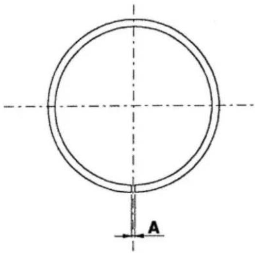
Slot packing system
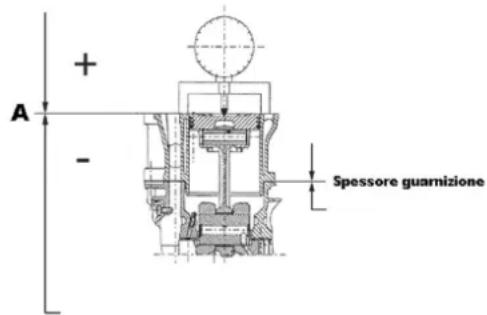
Characteristic
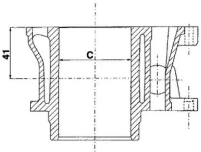
Shimming system for limiting the compression ratio
Rc: 11÷12:1
The measure «A» to take is a piston recess value that indicates how much the plane formed by the
piston top goes below the plane formed by the top of the cylinder. The more the piston recesses into the cylinder, the smaller the base gasket to apply (to recover the compression ratio) and vice versa.
N.B.
THEBMEASUREB«A»BMUSTBBEBTAKENBWITHOUTBANYBGASKETBINSTALLEDBETWEENBCRANKCASE ANDBCYLINDERBANDBAFTERBHAVINGBRESETBTHEBCOMPARATOR,BCOMPLETEBWITHBSUPPORT,BONBA RECTIFIEDBSURFACE
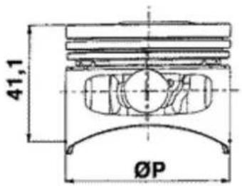
THICKNESSB200
NameBMeasureBABThickness
| Gasket thickness 200 | 1,7 ÷ 1,6 | 0,4 ± 0,05 |
| Gasket thickness 200 | 1,6 ÷ 1,4 | 0,6 ± 0,05 |
| Gasket thickness 200 | 1,4 ÷ 1,3 | 0,8 ± 0,05 |
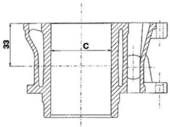
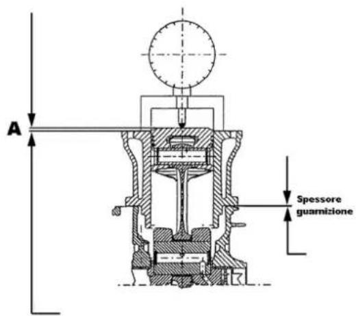
Characteristic
ShimmingBsystemBforBlimitingBtheBcompressionBratioB125
$$ \mathrm{Rc} = 1 2 \div 1 3: 1 $$
The measure «A» to take is a piston protrusion value that indicates how much the plane formed by the piston top protrudes from the plane formed by the top of the cylinder. The more the piston protrudes from the cylinder, the more the base gasket to apply (to recover the compression ratio) and vice versa.
N.B.
THEBMEASUREB«A»BMUSTBBEBTAKENBWITHOUTBANYBGASKETBINSTALLEDBBETWEENBCRANKCASE ANDBCYLINDER.
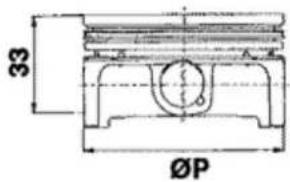
THICKNESSB125
NameBMeasureBABThickness
| Gasket thickness 125 | 2,2 ÷ 2,4 | 0,4 ± 0,05 |
| Gasket thickness 125 | 2,4 ÷ 2,6 | 0,6 ± 0,05 |
Oversizes
OVERSIZE 125CC ENGINE
Name Description Dimensions Initials Quantity
| Third uprated scraper ring lining | 57,6 x 2,5,A,0,15 ÷ 0,35 | ||
| Third uprated scraper ring lining | 57,6 x 1,A,0,10 x 30 | ||
| Third uprated compression lining | 57,6 x 1,A,0,15 ÷ 0,30 | ||
| Second uprated scraper ring lining | 57,4 x 2,5,A,0,15 ÷ 0,35 | ||
| Second uprated scraper ring lining | 57,4 x 1,A,0,10 ÷ 0,30 | ||
| Second uprated compression lining | 57,4 x 1,A,0,15 ÷ 0,30 | ||
| First uprated scraper ring lining | 57,2 x 2,5,A,0,15 ÷ 0,35 | ||
| First uprated scraper ring lining | 57,2 x 1,A,0,10 ÷ 0,30 | ||
| Compression lining 1° greater | 57,2 x 1,A,0,15 ÷ 0,30 | ||
| Scraper ring lining | 57 x 2,5 | A | 0,15 ÷ 0,35 |
| Scraper ring lining | 57 x 1 | A | 0,10 ÷ 0,30 |
| Compression lining | 57 x 1 | A | 0,15 ÷ 0,30 |
OVERSIZE 200CC ENGINE
Name Description Dimensions Initials Quantity
| Scraper ring lining | 72 x 2,5 | A | 0,20 ÷ 0,40 |
| Scraper ring lining | 72 x 1 | A | 0,20 ÷ 0,40 |
Name Description Dimensions Initials Quantity
| Compression lining | 72 x 1,5 | A | 0,15 ÷ 0,30 |
Products
RECOMMENDED PRODUCTS
Product Description Specifications
| TUTELA ZC 90 | Rear hub oil | Oil SAE 80W/90 of higher quality than API GL3 specifications |
| Selenia Air Filter Oil | Air filter sponge oil | Mineral oil with specific additives to increase adhesion ISO VG 150 |
| SYSTEM TW 249 AREXONS | Complex calcium soap grease NLGI 1-2 | Grease (brake command levers, gas) |
| SELENIA HI Scooter 4 Tech | Oil for four stroke engines | Oil for flexible transmission lubrication (gas control) |
| TUTELA TOP 4 | Brake fluid | Synthetic fluid SAE J1703, NHTSA 116 DOT 4, ISO 4925 |
| PARAFLU 11 FE (Diluted) | Coolant | Anti-freezing fluid based on monoethylene glycol, CUNA NC 956-16 |
| MONTBLANC MOLYBDENUM GREASE | Grease for driven pulley shaft compensating ring and mobile driven pulley sliding seat | Molybdenum bisulphide grease |
| TUTELA ZETA 2 | Grease for steering, seats of pin and swing arm | Lithium soap and zinc oxide grease NLG12 |
INDEX OF TOPICS
TOOLING
TOOLING
Stores code Description
| 001330Y | Steering seat installer, to be fitted with parts: 001330Y009-For lower seat, 001330Y013-For upper seat | 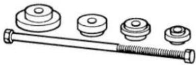 |
| 001467Y009 | Bell for bearings external ∅ 50 mm | 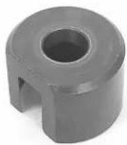 |
| 001467Y017 | Bell for bearings external ∅ 39 mm | 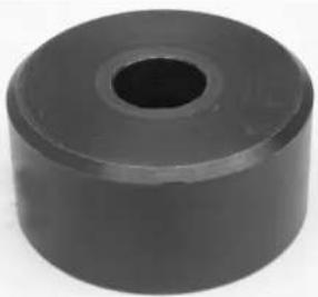 |
| 001467Y014,15 mm pliers | 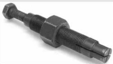 | |
| 002095Y,Engine support | ||
| 002465Y,Pliers for snap rings | 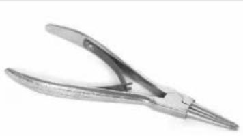 | |
| 006029y | Drift for fitting thrust ring seats on steering tube | 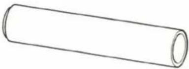 |
Stores code Description
008564Y Flywheel extractor
020004Y
Drift for removing thrust rings from steering head tube
natural_image
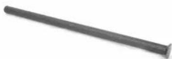
A dark, elongated metal rod or nail against a white background (no text or symbols visible)020021y Front suspension overhaul kit
natural_image
Technical line drawing of a mechanical press or clamping device with no visible text or symbols020036y Drift
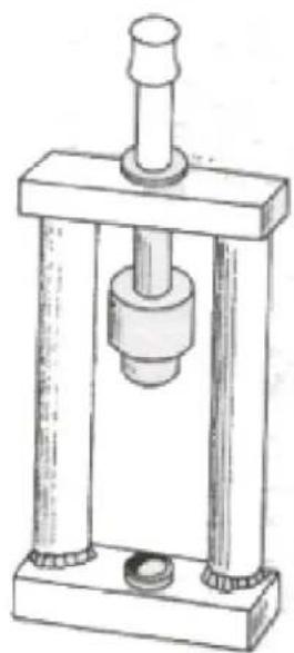
natural_image
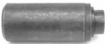
Close-up of a cylindrical mechanical component with a flanged end (no visible text or markings)Stores code Description
| 020037y Drift | 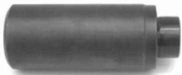 | |
| 020038y Drift | 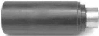 | |
| 020055Y | Steering tube ring nut spanner | 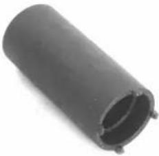 |
| 020074Y Crankshaft aligning tool | 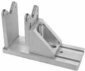 | |
| 020150Y | Support for air heater "METABO HG 1500/2" | 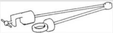 |
| 020151Y Air heater "METABO HG 1500/2" | 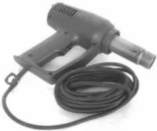 | |
Stores code Description
020193Y Oil pressure gauge
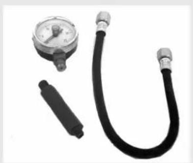
natural_image
Close-up of a pressure gauge and two black tubing (no text or symbols visible)020262Y Crankcase detachment plate
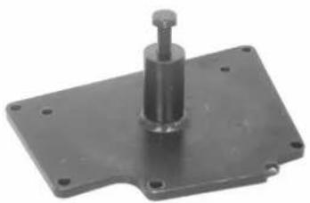
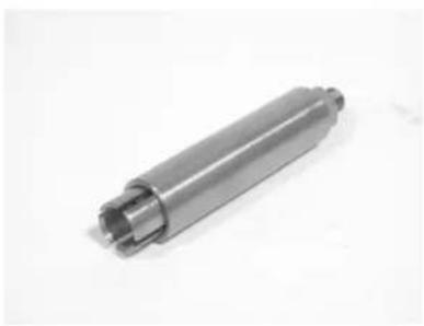
natural_image
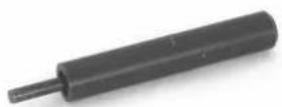
Metal mechanical component with a cylindrical pin and mounting base (no text or symbols visible)020263Y Protective sheath
020287Y Piston band clamps (Engine 125cc)
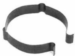
natural_image
Close-up of a black metal braided or wire loop component (no text or symbols visible)020306Y Valve sealing ring drift
020319Y Immobilizer control test

Stores code Description
020329Y Pump MITYVAC
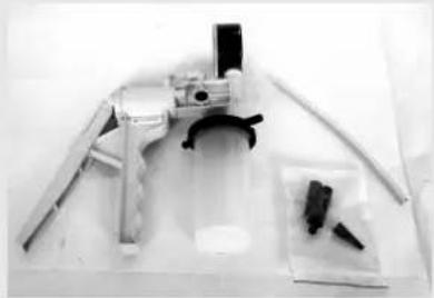
natural_image
Black-and-white photo of a medical or laboratory apparatus with no visible text or symbols020330Y
Timing light for two- and four-stroke engines
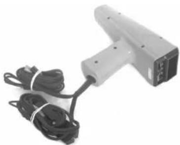
natural_image
Exterior view of a handheld electronic device with coiled cables (no visible text or symbols)020331Y Digital multimeter
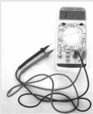
natural_image
Digital multimeter with connected cables and a power supply, no visible text or symbols on the device itself.020332Y Digital rpm counter

natural_image
Black electronic device with a digital display and coiled cable, labeled 'RF-5' (no readable text beyond label)Stores code Description
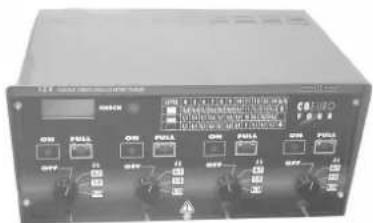
020333Y Single battery charger
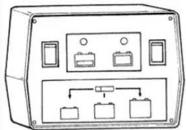
natural_image
Front view diagram of an electrical enclosure with multiple compartments and control panel (no text or labels)020334Y Multiple battery charger
020335Y Magnetic stand and comparator
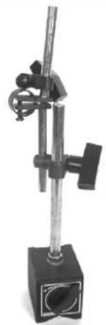
natural_image
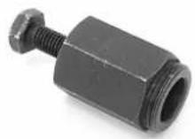
Laboratory glassware setup with adjustable arms and a central rod (no visible text or labels)020357Y 32 x 35 mm adaptor
020359Y
42 x 47 mm hub bearing fitting adaptor
020360Y 52 x 55 mm adaptor
020363Y 20mm guide
020364Y 25 mm guide
020365y 22 mm guide
Stores code Description
020368Y driving pulley stop wrench
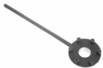
natural_image
Metal mechanical lever with flange and bolt holes (no text or symbols)020375Y Adapter 28 x 30 mm
020376Y Handle for punches
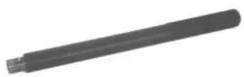
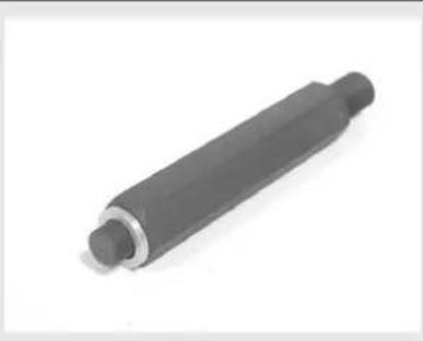
natural_image
Black cylindrical mechanical shaft or rod with flanged ends, isolated on white background (no text or symbols)020382Y
Tool for removing valve cotters equipped with part 012
020382Y011 Bushing (valve remover)
020393Y
Piston band clamps (Engine 200 - 250 cc)
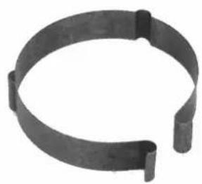
natural_image
Circular metal bracket with rounded ends and a small notch at the bottom (no text or symbols)020409Y Multimeter adapter (Peak voltage measurement)
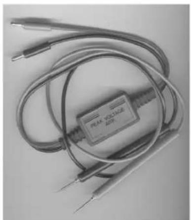
natural_image
Close-up of a black electronic device with coiled wires and two metallic probes (no visible text or symbols)Stores code Description
| 020412Y 15 mm guide | 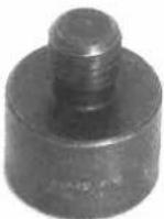 | |
| 020414Y | 28-mm guide - Hub bearing as-sembly | 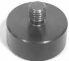 |
| 020423Y driven pulley stop key | 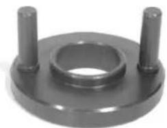 | |
| 020424Y | Driven pulley roller casing drift | |
| 020425Y Flywheel-side oil guard punch | 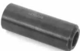 | |
| 020426Y Piston fitting fork | 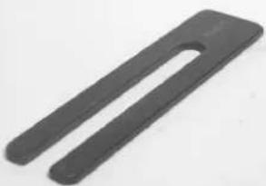 | |
Stores code Description
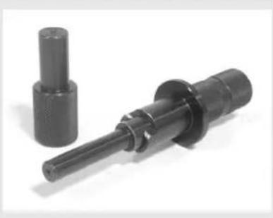
020430Y Pin retainers installation tool (Engine 125cc)
natural_image
Two black mechanical components with cylindrical and flanged ends, no visible text or symbols020431Y Valve oil seal extractor
natural_image
Metal cylindrical mechanical part with flanged ends, isolated on white background (no text or symbols)020434Y Oil pressure gauge connection
natural_image
Close-up of a cylindrical mechanical component with flanged ends and a tapered shaft (no text or symbols visible)020439Y 17 mm guide
020440Y Water pump overhaul tool
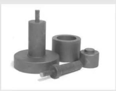
natural_image
Three gray mechanical components with no visible text or symbols020441y 26 x 28 mm adapter
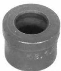
natural_image
Close-up of a cylindrical mechanical part with a hollow center (no visible text or markings)Stores code Description
| 020442Y pulley stop wrench | 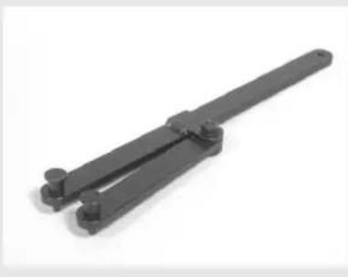 | |
| 020444Y | Driven half pulley spring compressor tool | 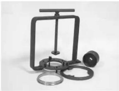 |
| 020455Y 10-mm guide | ||
| 020456Y ∅ 24 mm adapter | ||
| 020477Y Adapter 37 mm | 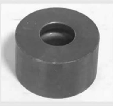 | |
| 020483Y 30 mm guide | 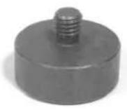 | |
| 020488y | Piston pin retainer fitting tool (200 cc engine) | 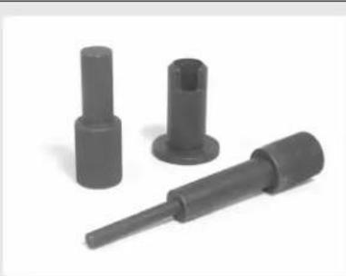 |
Stores code Description
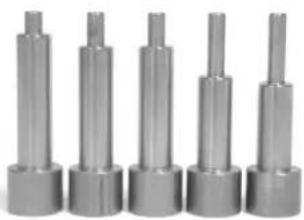
020489Y
Hub cover support pillar kit
natural_image
Six identical metallic cylindrical mechanical components arranged in a row (no text or symbols visible)020565Y Compass flywheel stop spanner
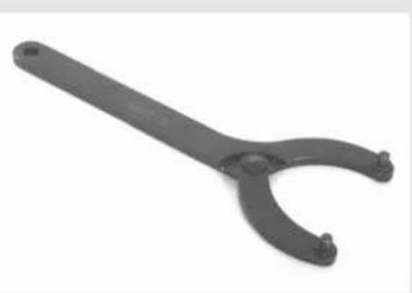
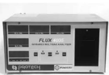
natural_image
Black adjustable tool with curved handle and two small feet (no text or symbols visible)494929 Exhaust gas analyser
INDEX OF TOPICS
MAINTENANCE
Maintenance chart
EVERY 2 YEARS
Action
| Secondary air filter (external/internal) - Cleaning |
| Cooling Fluid - Replacement |
| Brake fluid - Change |
EVERY 3000 KM
Action
Engine Oil - Level Check/Top up
AT 1000 KM OR 4 MONTHS
70'
Action
| Hub oil level - Check / Replacement |
| Idling speed (*) - Adjustment |
| Acceleration command - Adjustment |
| Steering - Adjust |
| Brake command levers - Lubrication |
| Brake pads - Check condition + wear |
| Brake fluid level - Check |
| Nuts, bolts and fasteners - Check |
| Electrical system and battery - Check |
| Vehicle and brake test - Road test |
Safety)locks:)see)Before)delivery)chapter.)(*)See)rules
AT 6000 KM OR 12 MONTHS
130'
Action
| Engine oil - Replacement |
| Hub oil level - Check / Replacement |
| Spark plug/Electrode gap - Check/Change |
| Air Filter - Cleaning |
| Oil filter - Replacement |
| Valve clearance - Check |
| 200 cc Valve play - Check |
| Variator rollers - Check or Replacement |
Action
| Driving belt - Check / Replacement |
| Cooling fluid level - Check |
| Brake pads - Check condition + wear |
| Brake fluid level - Check |
| Electrical system and battery - Check |
| Tires-inflation and wear - Check |
| Vehicle and brake test - Road test |
AT 12000 KM OR 24 MONTHS AND AT 60000 KM
135'
Action
| Engine oil - Replacement |
| Hub oil level - Check / Replacement |
| Spark plug/Electrode gap - Check/Change |
| Air Filter - Cleaning |
| Oil filter - Replacement |
| Idling speed (*) - Adjustment |
| Acceleration command - Adjustment |
| Variator rollers - Check or Replacement |
| Driving belt - Check / Replacement |
| Cooling fluid level - Check |
| Steering - Adjust |
| Brake command levers - Lubrication |
| Brake pads - Check condition + wear |
| Brake fluid level - Check |
| Transmissions - Lubricate |
| Nuts, bolts and fasteners - Check |
| Suspensions - Check |
| Electrical system and battery - Check |
| Headlight - adjustment |
| Tires-inflation and wear - Check |
| Vehicle and brake test - Road test |
| Safety)locks:)see)Before)delivery)chapter.)(*)See)rules |
AT 18000 KM AND AT 54000 KM (125)
100'
Action
| Engine oil - Replacement |
| Hub oil level - Check / Replacement |
| Spark plug/Electrode gap - Check/Change |
| Air Filter - Cleaning |
| Oil filter - Replacement |
| Variator rollers - Check or Replacement |
| Driving belt - Check / Replacement |
| Cooling fluid level - Check |
| Radiator - External cleaning/Check |
| Brake pads - Check condition + wear |
| Brake fluid level - Check |
| Electrical system and battery - Check |
| Tires-inflation and wear - Check |
| Vehicle and brake test - Road test |
AT 18000 KM AND AT 54000 KM (200)
140'
Action
| Engine oil - Replacement |
| Hub oil level - Check / Replacement |
| Spark plug/Electrode gap - Check/Change |
| Air Filter - Cleaning |
| Oil filter - Replacement |
| Valve play 200 - recording |
| Variator rollers - Check or Replacement |
| Driving belt - Check / Replacement |
| Cooling fluid level - Check |
| Radiator - External cleaning/Check |
| Brake pads - Check condition + wear |
| Brake fluid level - Check |
| Electrical system and battery - Check |
| Tires-inflation and wear - Check |
| Vehicle and brake test - Road test |
AT 24000 KM AND AT 48000 KM (125)
190'
Action
| Engine oil - Replacement |
| Hub oil level - Check / Replacement |
| Spark plug/Electrode gap - Check/Change |
| Air Filter - Cleaning |
| Oil filter - Replacement |
| Valve clearance - Check |
| Idling speed (*) - Adjustment |
| Acceleration command - Adjustment |
| Variator rollers - Check or Replacement |
| Driving belt - Check / Replacement |
| Cooling fluid level - Check |
| Steering - Adjust |
| Brake command levers - Lubrication |
| Brake pads - Check condition + wear |
| Brake fluid level - Check |
| Transmissions - Lubricate |
| Nuts, bolts and fasteners - Check |
| Suspensions - Check |
| Electrical system and battery - Check |
| Headlight - adjustment |
| Tires-inflation and wear - Check |
| Vehicle and brake test - Road test |
| Safety)locks:)see)Before)delivery)chapter.)(*)See)rules |
AT 24000 KM AND AT 48000 KM (200)
150'
Action
| Engine oil - Replacement |
| Hub oil level - Check / Replacement |
| Spark plug/Electrode gap - Check/Change |
| Air Filter - Cleaning |
| Oil filter - Replacement |
| Valve clearance - Check |
| Idling speed (*) - Adjustment |
| Acceleration command - Adjustment |
Action
| Variator rollers - Check or Replacement |
| Driving belt - Check / Replacement |
| Cooling fluid level - Check |
| Steering - Adjust |
| Brake command levers - Lubrication |
| Brake pads - Check condition + wear |
| Brake fluid level - Check |
| Transmissions - Lubricate |
| Nuts, bolts and fasteners - Check |
| Suspensions - Check |
| Electrical system and battery - Check |
| Headlight - adjustment |
| Tires-inflation and wear - Check |
| Vehicle and brake test - Road test |
Safety)locks:)see)Before)delivery)chapter.)(*)See)rules
AT 30000 KM AT 42000 KM AND AT 66000 KM
90'
Action
| Engine oil - Replacement |
| Hub oil level - Check / Replacement |
| Spark plug/Electrode gap - Check/Change |
| Air Filter - Cleaning |
| Oil filter - Replacement |
| Variator rollers - Check or Replacement |
| Driving belt - Check / Replacement |
| Cooling fluid level - Check |
| Brake pads - Check condition + wear |
| Brake fluid level - Check |
| Electrical system and battery - Check |
| Tires-inflation and wear - Check |
| Vehicle and brake test - Road test |
AT 36000 KM (125)
205'
Action
| Engine oil - Replacement |
| Hub oil level - Check / Replacement |
| Spark plug/Electrode gap - Check/Change |
| Air Filter - Cleaning |
| Oil filter - Replacement |
| Valvle play 125 - recording |
| Idling speed (*) - Adjustment |
| Acceleration command - Adjustment |
| Variator rollers - Check or Replacement |
| Driving belt - Check / Replacement |
| Cooling fluid level - Check |
| Radiator - External cleaning/Check |
| Steering - Adjust |
| Brake command levers - Lubrication |
| Brake pads - Check condition + wear |
| Flexible brake lines - Change |
| Brake fluid level - Check |
| Transmissions - Lubricate |
| Nuts, bolts and fasteners - Check |
| Suspensions - Check |
| Electrical system and battery - Check |
| Headlight - adjustment |
| Tires-inflation and wear - Check |
| Vehicle and brake test - Road test |
Safety)locks:)see)Before)delivery)chapter.)(*) See)rules
AT 36000 KM (200)
245'
Action
| Engine oil - Replacement |
| Hub oil level - Check / Replacement |
| Spark plug/Electrode gap - Check/Change |
| Air Filter - Cleaning |
| Oil filter - Replacement |
| Valve play 200 - recording |
Action
| Idling speed (*) - Adjustment |
| Acceleration command - Adjustment |
| Variator rollers - Check or Replacement |
| Driving belt - Check / Replacement |
| Cooling fluid level - Check |
| Radiator - External cleaning/Check |
| Steering - Adjust |
| Brake command levers - Lubrication |
| Brake pads - Check condition + wear |
| Flexible brake lines - Change |
| Brake fluid level - Check |
| Transmissions - Lubricate |
| Nuts, bolts and fasteners - Check |
| Suspensions - Check |
| Electrical system and battery - Check |
| Headlight - adjustment |
| Tires-inflation and wear - Check |
| Vehicle and brake test - Road test |
| Safety)locks:)see)Before)delivery)chapter.)(*)See)rules |
AT 72000 KM
260'
Action
| Engine oil - Replacement |
| Hub oil level - Check / Replacement |
| Spark plug/Electrode gap - Check/Change |
| Air Filter - Cleaning |
| Oil filter - Replacement |
| Valve clearance - Check |
| Valve play 200 - recording |
| Idling speed (*) - Adjustment |
| Acceleration command - Adjustment |
| Variator rollers - Check or Replacement |
| Driving belt - Check / Replacement |
| Cooling fluid level - Check |
Action
| Radiator - External cleaning/Check |
| Steering - Adjust |
| Brake command levers - Lubrication |
| Brake pads - Check condition + wear |
| Flexible brake lines - Change |
| Brake fluid level - Check |
| Transmissions - Lubricate |
| Nuts, bolts and fasteners - Check |
| Electrical system and battery - Check |
| Headlight - adjustment |
| Tires-inflation and wear - Check |
| Vehicle and brake test - Road test |
| Safety)locks:)see)Before)delivery)chapter.)(*)See)rules |
Carburettor
Carburettor
- Disassemble all carburettor components, accurately wash them in solvent, then dry them with compressed air. To ensure thorough cleaning, pay special attention to the passages in the carburettor body.
- Carefully check the condition of all components.
- The throttle must slide freely in the chamber, if the play is excessive because or wear, replace the throttle.
- Replace the carburettor if the chamber shows signs of wear as to prejudice the valve's regular seal or free sliding (though it is new).
- When reassembling the carburettor, it is a good rule to replace the gaskets.
WARNING
PETROL IS HIGHLY EXPLOSIVE. ALWAYS FIT NEW SEALS AND GASKETS TO PREVENT LEAKAGE.
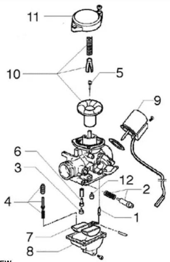
Membrane cover Gas valve spring Conical pin support Conical pin spring Conical pin Gas valve membrane Automatic starter Idle speed adjustment screw Return valve rockers Idle mixture adjustment screw Float pin Return pump unit Float Basin Minimum jet Maximum jet Emulsifier Basin drainage screw.
Checking the spark advance
- To check the ignition advance, use the strobo-scopic lamp with induction collet connected to the spark plug power supply cable.
- Connect the induction collet according to the right polarity (the arrow on the collet must be facing the spark plug).
- Set the lamp selector to the central position (1 spark = 1 driving shaft revolution as in 2 stroke engines).
- Start the engine and check that the lamp is in good working order and that the rpm counter reads high speeds too (e.g. 8,000 rpm).
- If you detect abnormal flashes or rpm reads, increase the resistive load on the spark plug supply line (10 - 15 KΩ in series with the H.V. cable).
- Remove the slit plastic cap on the flywheel cover.
- Adjust the lamp flash dephasing corrector to make the reference on the flywheel cover collimate with the level on the water pump drive. Read the advance degrees indicated by the strobo-scopic lamp.
- Check that the advance degrees match the revolution speed as indicated in the tables.
- In case of abnormal values, check the Pick-Up and the control unit supplies (positive-negative); replace the control unit, if required.
- A new control unit prevents the engine from rotating at over 2,000 rpm.
natural_image
Sketch of a car's side profile showing the front grille and seat (no text or symbols)- The programmed control unit allows the engine revolution within the prescribed limits.
Characteristic
Ignition advance (before T.D.C) 125
10^ ± 1^ at 2000 rpm - 34^ ± 1^ at 6000 rpm
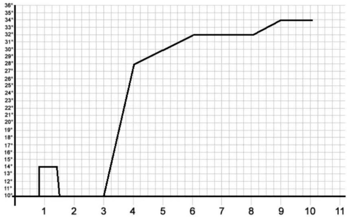
Ignition advance (before T.D.C)
10^ ± 1^ at 2000 rpm - 32^ ± 1^ at 6500 rpm
Spark advance variation
VERSION 200
Specification Desc./Quantity
| Spark suppression | First threshold: 1 spark out of 7 Second threshold: 2 sparks out of 3 |
| Version 200: Restoration threshold | First threshold: 9900 ±50 Second threshold: 10100 ±50 |
| Version 200: Tripping threshold | First threshold: 9800 ±50 Second threshold: 10000 ±50 |
VERSION 125
Specification Desc./Quantity
| Tripping threshold | First threshold: 10700 ±50Second threshold: 11000 ±50 |
| Restoration threshold | First threshold: 10600 ±50Second threshold: 10900 ±50 |
| Spark suppression | First threshold: 1 spark out of 7Second threshold: 2 sparks out of 3 |
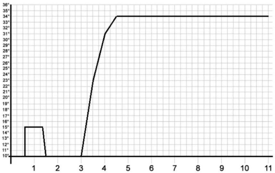
line
| x | y | |----|------| | 1 | 15° | | 2 | 10° | | 3 | 10° | | 4 | 31° | | 5 | 34° | | 6 | 34° | | 7 | 34° | | 8 | 34° | | 9 | 34° | | 10 | 34° | | 11 | 34° |Spark plug
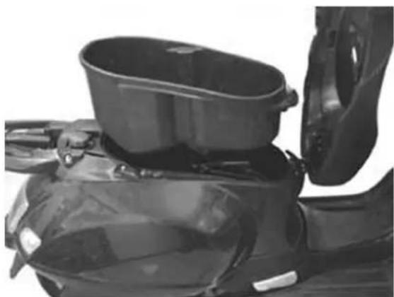
- Rest the vehicle on the central stand.
-Open the saddle and extract the helmet compartment - Disconnect the spark plug H.V. cable cap.
- Unscrew the spark plug, using the spanners supplied.
- Inspect the spark plug, the insulator's integrity, too worn or sooty electrodes, sealing washer state, and measure the distance between the electrodes using the special thickness gauge.
- Adjust the distance, if required, by bending the
natural_image
Close-up of a black scooter's front bumper and seat, showing no text or symbolsside electrode carefully. In case of irregularity, replace the spark plug with one of the recommended type.
- Insert the spark plug with the proper inclination, and screw it thoroughly by hand, then tighten it using the special wrench.
- Insert the cap over the spark plug thoroughly and proceed to re-assembly
CAUTION
THEBSPARKBPLUGBMUSTBBEBREMOVEDBWITH COLDBENGINE.BTHEBSPARKBPLUGBSHOULDBBEBRE- PLACEDBEVERYB12,000BKM.BTHEBUSEBOFBNON- CONFORMINGBIGNITIONBCONTROLLERS,BAND SPARKBPLUGSBOTHERBTHANBTHOSEBPRE- SCRIBEDBCANBSERIOUSLYBDAMAGEBTHEBENGINE.
Characteristic
SparkBplugB125
CHAMPION RG 4 HC
SparkBplugB200
CHAMPION RG 6 YC
ElectrodeBdistance
0.7-0.8 mm
LockingBtorquesB(N*m)
SparkBplugB12B÷B14
natural_image
Close-up of automotive engine components including hoses and valves (no visible text or symbols)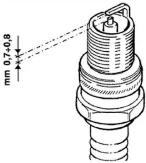
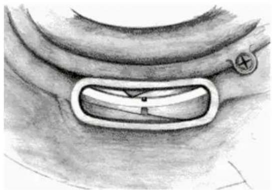
HubBoil
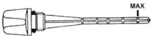
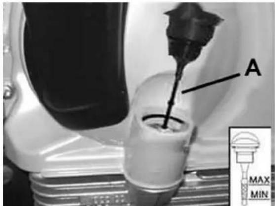
Check
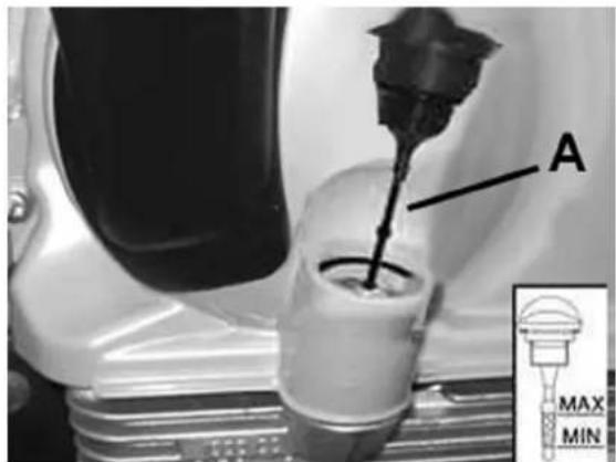
- Take the vehicle to a flat ground and rest it on the central stand.
- Unscrew the oil bar «A», dry it with a clean cloth and reinsert it, screwing it in thoroughly.
- Pull out the bar and check that the oil level is close to the bar bottom notch (see figure); if the level is below the MAX notch, restore the proper amount of oil in the hub.
natural_image
Technical line drawing of a mechanical component with no visible text or symbols- Screw the oil bar back on, checking that it is tightly in place.
The notches on the hub oil level bar, with the exception of that indicating the MAX level, refer to some of the manufacturer's other models and have no specific function as far as regards this vehicle.
Replacement
- Remove the oil loading cap «A».
- Remove the oil drainage cap «B» and let the oil drain out completely.
- Tighten the drainage cap again and fill the hub with oil.
RecommendedBproducts TUTELABZCB90BRearBhubBoil
Oil SAE 80W/90 of higher quality than API GL3 specifications
Characteristic
RearBhubBoil
Capacity \~ 150cc
LockingBtorquesB(N\*m)
HubBoilBdrainBscrewB15B÷B17BNm
AirBfilter
Cleaning (Every 12,000 Km):
- Wash with water and shampoo.
- Dry with light jets of compressed air and wipe with a clean cloth.
- Soak with a 50% fuel-oil mixture.
- Let the filter cartridge drip and then squeeze it between the hands without wringing.
- Refit the filter element.
CAUTION
DO NOT RUN THE ENGINE IF THE AIR FILTER IS NOT IN PLACE AS THIS WOULD RESULT IN EXCESS-
IVEBWEARBOFBTHEBCYLINDERBANDBPISTONBASBWELLBASBINBDAMAGEBTOBTHEBCARBURETTOR.
CAUTION
IFBTHEBVEHICLEBHASBRIDDENBONBDUSTYBROADS,BTHEBAIRBFILTERBMUSTBBEBCLEANEDBMOREBFREQUENTLYBTHANBWHATBINDICATEDBINBTHEBSCHEDULEDBMAINTENANCEBTABLE.
RecommendedBproducts
SeleniaBAirBFilterBOilBAirBfilterBspongeBoil
Mineral oil with specific additives to increase adhesion ISO VG 150
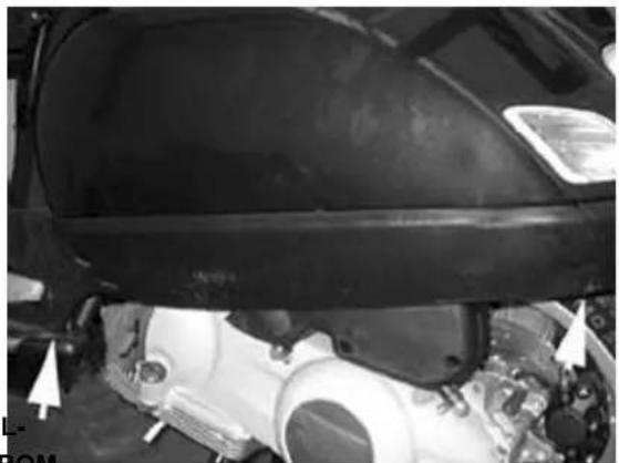
- Remove the left footboard and the left side panel as described in Chapter Bodywork.
- Remove the cleaner cap after loosening the 9 fixing screws.
- Pull out the filter element.
- Replace the air filter with a new one.
N.B.
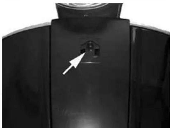
CHECKBANDBIFBNECESSARYBBLOWBTHEBAIRBFILTERBEVERYB6,000BKM.BDIRECTBTHEBAIRBJETBFROMTHEBINSIDEBTOBTHEBOUTSIDEBOFBTHEBFILTERB(I.E.INBTHEBOPPOSITEBDIRECTIONBTOBTHEBAIRBFLOWDURINGBNORMALBENGINEBOPERATION).BEVERY6,000BKM,BDURINGBTHEBSCHEDULEDBSERVICE,BRE-MOVEBTHEBRETAINER,BTAKEBOFFBTHEBRUBBERCAPBFROMBUNDERBTHEBFILTERBBOXBASBSHOWNINBTHEBFIGUREBANDBDRAINBANYBOILBRESIDUES.
natural_image
Close-up of a car's engine compartment with visible mechanical components and a headlight (no text or symbols)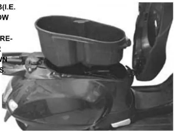
natural_image
Close-up of a scooter's front bumper and seat assembly (no visible text or symbols)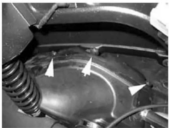
natural_image
Close-up of a car's engine compartment showing hoses and structural elements (no visible text or symbols)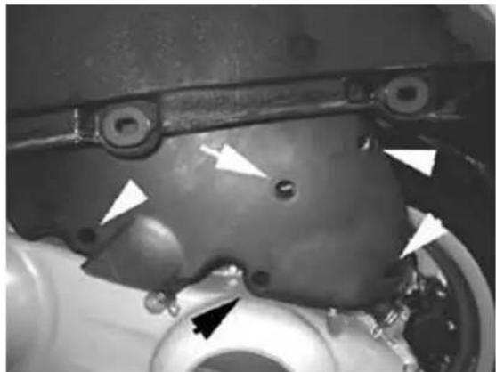
natural_image
Close-up of a mechanical component with white arrows pointing to features, no visible text or symbols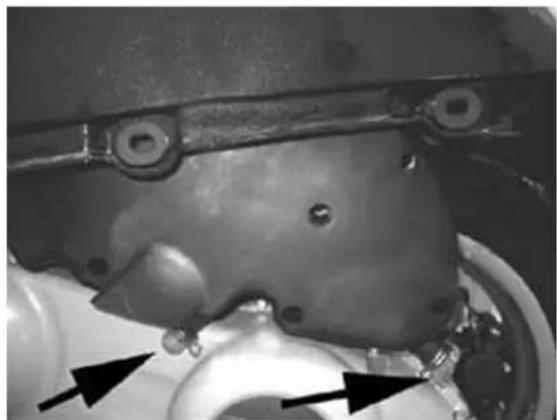
natural_image
Close-up of a mechanical component with mounting holes and a central shaft, showing no visible text or symbols.EngineBoil
Engine oil is used in 4-stroke engines in order to lubricate the timing gears, the bench supports and the thermal group. An insufficient quantity of oil can cause serious damage to the engine itself. In all 4T engines, the decay of the oil characteristics, as well as a certain level of consumption, should be considered normal, especially during running in. Consumption can particularly reflect the conditions of use (e.g.: when driving at full acceleration all the time, oil consumption increases).
Replacement
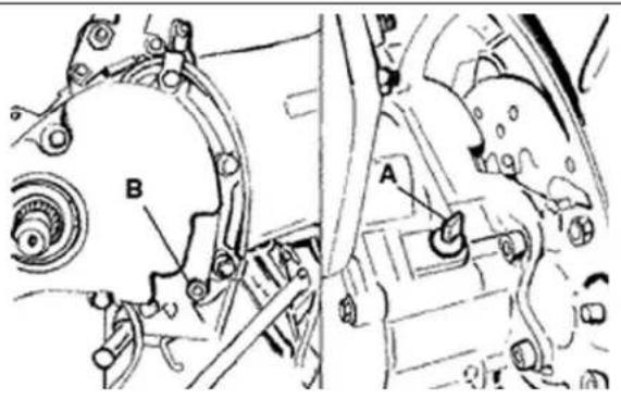
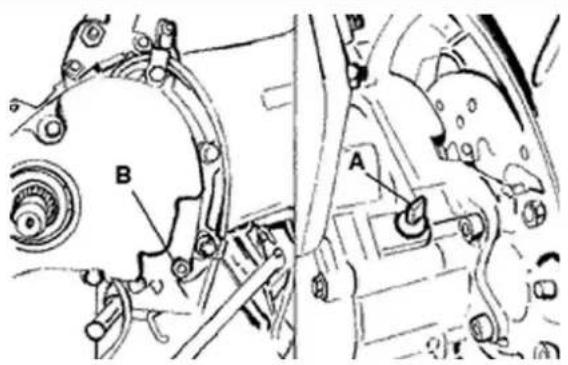
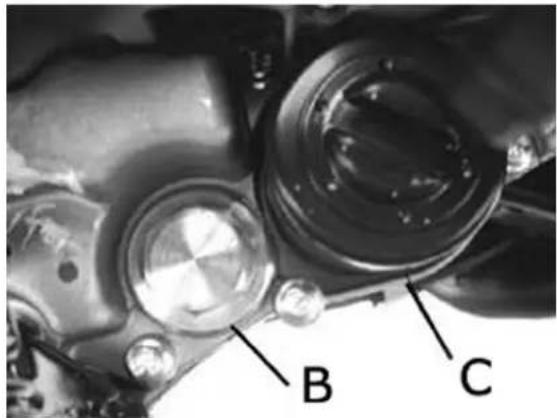
- Oil and filter should be replaced every 6,000 km. The engine should be emptied by draining the oil from the pre-filter drainage tap «B» of the net pre-filter on the flywheel side; Moreover, to facilitate the oil drainage, loosen the cap/bar «A». Once the oil has been drained from the drainage tap, loosen the cartridge oil filter «C» and remove it as described below.
- Make sure that the O-rings of pre-filter and drainage cap are not worn.
- Lubricate the O-rings and replace net filter and oil drainage cap; tighten at the prescribed torque.
- Install the new cartridge filter after lubricating the O-ring.
- Fill in the engine oil.
- Since a certain quantity of oil still remains in the circuit, the fill-up should be carried out with oil from cap «A». Then start up the vehicle, leave it running for a few minutes and switch it off: after around 5 minutes, check the level and top up if necessary withoutBeverBexceedingBtheBMAX
level. The cartridge filter should be replaced every time the oil is changed. For top up and replacement, use new oil type.
N.B.
RENEWBTHEBOILBWHENBTHEBENGINEBISBHOT.
RecommendedBproducts
SELENIABHIBScooterB4BTechBEngineBoil
Synthetic oil SAE 5W/40 of higher quality than
API SJ specifications
Characteristic
OilBtop-up
600 ÷ 650 cc
Check
This operation should be carried out on cold engine, according to the following procedure:
Rest the vehicle on the central stand and on a flat ground. Unscrew the cap/bar «A», dry it with a clean cloth and reinsert it, screwing it thoroughly. Remove the cap/bar again and check that the level is between the max and min levels; top up, if required.
The MAX level reference means that in the engine there is an oil quantity of about 1100 cc.
If the check is carried out after the vehicle has been used, and therefore with a hot engine, the level line will be lower; in order to carry out a correct check it is necessary to wait at least 10 minutes after
the engine has been stopped, so as to get the correct level.
Oil top up
The oil should be topped up after having checked the level and in any case by adding oil without ever exceeding the MAX level.
The restoration level between the MIN and MAX levels implicates a quantity of oil \~400 cc.
Oil pressure warning light
The vehicle is equipped with a warning light on the instrument panel that lights up when the key is turned to the «ON» position. However, this light should switch off once the engine has been started.
If the indicator turns on while braking, with idle engine or in a curve, stop the engine and check the level and the lubrication system.
Checking the ignition timing
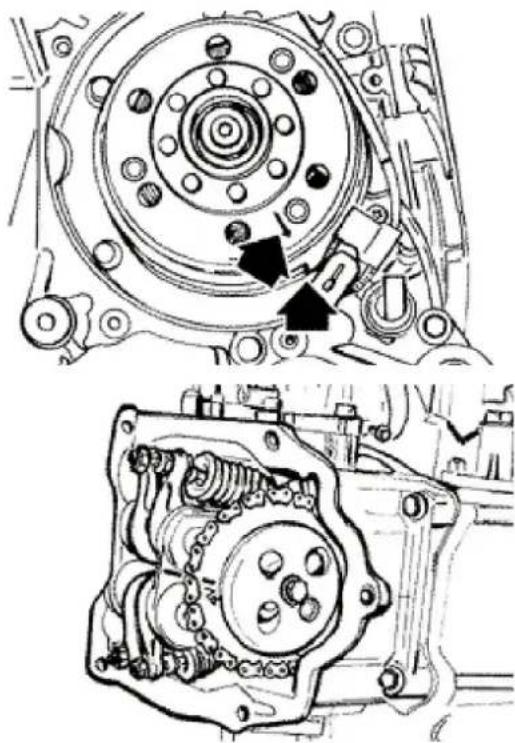
- Remove the four fixing screws and detach the flywheel cover, with the water pump and hoses, from the engine.
- Turn the flywheel until the reference mark reaches the fine machining on the crankcase, as shown in the picture (TDC). Ensure the 4V mark, stamped on the camshaft drive pulley, is aligned with the reference mark on the head, as shown in the second figure. If the mark is on the opposite side of the sign stamped on the head, crank the engine so that the crankshaft computes a complete revolution.
- The TDC reference mark is also shown on the flywheel cooling fan and cover.
In order to use these markings, remove the spark plug and crank the crankshaft backwards, using a
natural_image
Technical line drawing of mechanical components, showing top and side views with no visible text or symbolsretaining tool to hold the camshaft driving pulley.
N.B.
IFBTHEBTIMINGBASSEMBLYBISBNOTBINBPHASE, BAD-JUSTBITBASBREQUIRED.
CoolingBsystem
FillingBtheBengineBcoolingBfluid
The fluid level inspection should be carried out every 6,000 km when the motor is cold, following the methods indicated below:
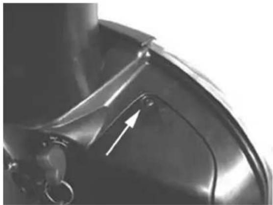
- Rest the vehicle on the central stand and on a flat ground.
- Loosen the screw shown in the figure and remove the expansion tank cover located on the right side of the vehicle.
- Top up, if the fluid level is near to or below the MIN level into the expansion tank. The fluid level should always be between the MIN and MAX level.
- The cooling fluid consists of a mixture of 50% demineralised water and ethylene glycol and corrosion inhibitors based anti-freeze solution.
CAUTION
natural_image
Close-up of a metallic mechanical component with a white arrow pointing to a feature (no text or symbols visible)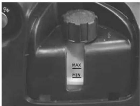
TOBPREVENTBTHEBCOOLANTBFROMBLEAKINGBOUT OFBTHEBEXPANSIONBTANKBDURINGBUSE,BBEBSURE TOBNEVERBEXCEEDBTHEBMAXBLEVELBWHENBRE-FILLING
BrakingBsystem
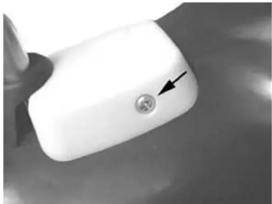
LevelBcheck
The front and rear brake fluid tanks are located on the pumps on the handlebar cover. Proceed as follows:
- Remove the brake pump cover.
- Rest the vehicle on the central stand with the handlebars in a central position;
- Check the fluid level through the hole shown in the figure. The level will go down to a certain extent due to lining wear.
natural_image
Close-up of a white plastic container with a circular button and an arrow pointing to it, placed on a surface (no text or symbols visible)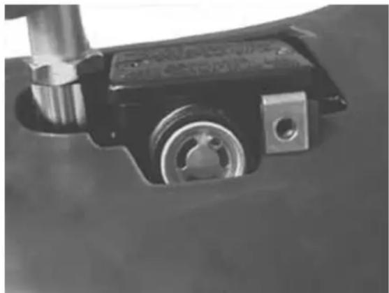
natural_image
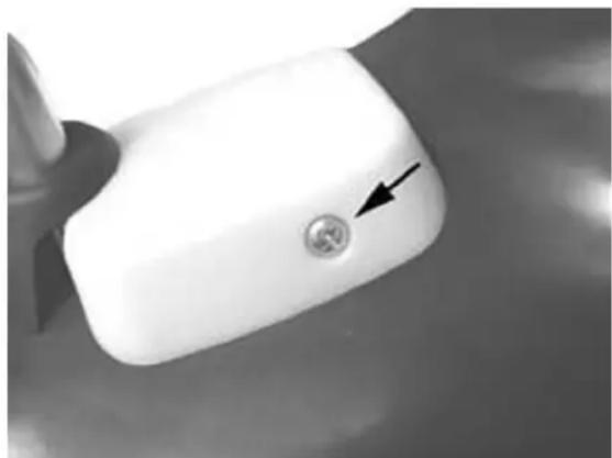
Close-up of a mechanical component with metallic parts and a circular feature (no visible text or symbols)Top-up
- Rest the vehicle on a flat ground and on the central stand.
- Remove the brake pump cover as shown in the figure.
natural_image
Close-up of a white plastic container with a circular button and an arrow pointing to it, placed on a surface (no text or symbols visible)- Check the brake fluid level by the special indicator located on the pump, as shown in the figure
- If the level is below minimum, fill by the screws shown in the figures
natural_image
Close-up of a mechanical component with a cylindrical housing and metallic components (no visible text or symbols)- Remove the gasket and fill with fluid DOT 4 to fully cover the indicator
- For re-assembly, perform the operations for removal in the reverse order according to the tightening torques of the tank cover screws.
CAUTION
KEEPBTHEBBRAKEBFLUIDBAWAYBFROMBTHEBSKIN, THEBEYESBANDBCLOTHING.BINBCASEBOFBCONTACT,BRINSEBGENEROUSLYBWITHBWATER.

natural_image
Close-up of a black electronic device with two circular buttons and an arrow pointing to it, mounted on a car (no visible text or symbols)THEBBRAKINGBCIRCUITBFLUIDBHASBABHIGHBCORROSIVEBPOWER.BTHEREFORE,BDURINGBANY LEVELBTOPBUPBOPERATIONS,BAVOIDBLETTINGBIT COMEBINTOBCONTACTBWITHBTHEBPAINTEDBPARTS. THEBBRAKINGBCIRCUITBFLUIDBISBHYGROSCOPIC, THATBISBTOBSAYBITBABSORBSBHUMIDITYBFROM THEBSURROUNDINGBAIR,BIFBTHEBHUMIDITYBCONTAINEDBINBTHEBBRAKEBFLUIDBISBOVERBABCERTAIN VALUEBITBWILLBRESULTBINBUNSATISFACTORY BRAKING.
CAUTION
natural_image
Close-up of a mechanical component with no visible text or symbolsNEVERBUSEBBRAKINGBFLUIDBFROMBCONTAINERS THATBHAVEBALREADYBBEENBOPENED, BORBPAR- TIALLYBUSED. BINBNORMALBWEATHERBCONDI- TIONS, BTHEBFLUIDBSHOULDBBEBREPLACEDBEVERY 20,000BKMBORBINBANYBCASEBEVERYB2BYEARS.
LockingBtorquesB(N*m)
BrakeBpumpBbasinBscrewsB15B÷B20
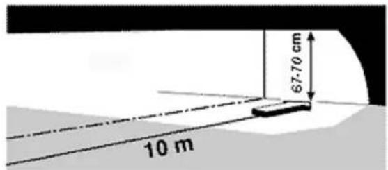
HeadlightBadjustment
- Place the vehicle in use conditions, with no load, with tyres inflated at the prescribed pressure on flat ground at 10 m from a white screen placed in dim light, making sure that the vehicle's axle is perpendicular to the screen.
- Trace a horizontal line on the screen at 67-70 cm above ground level.
- Remove the front radiator grill by the screw shown in the figure
- Turn the headlight on, switch on the dipped beam and check that the horizontal limit line between the dark zone and the illuminated zone does not fall above the horizontal line traced on the screen. To move the headlight, tighten or loosen the screw shown in the figure.
natural_image
Close-up of a black mechanical component with a white arrow pointing to a small knob (no text or symbols visible)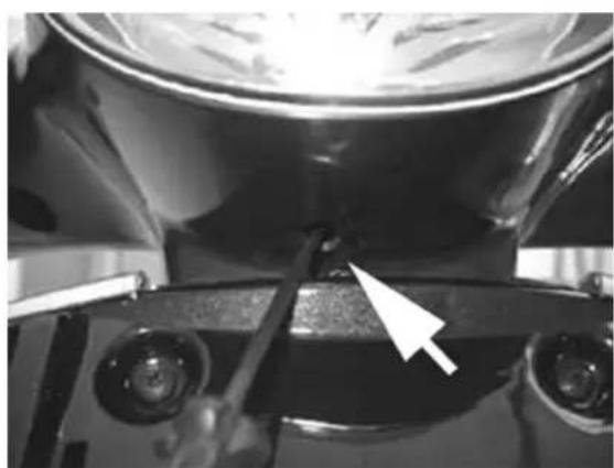
natural_image
Close-up of a mechanical component with a white arrow pointing to a small feature on the surface (no visible text or symbols)CO check
Remove the side, then remove the transmission side cooling air inlet so as to easily reach the flow adjustment screw
- Remove the gas cap on the exhaust pipe.
- Using the original washer, install the exhaust gas collection Kit union.
natural_image
Close-up of a mechanical assembly with hoses and springs (no visible text or symbols)- Suitably orientate the components.
- Close the gas outlet terminal of the tool.
- Start the engine and let it warn until the electric fan starts.
- Stop the engine.
natural_image
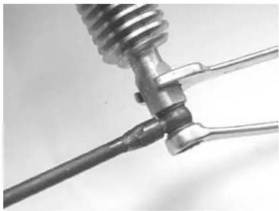
Close-up of a mechanical tool interacting with a coiled spring and two metal clamps (no text or symbols visible)- Disconnect the SAS check valve vacuum pipe from the «T» branch shown in the figure.
- Close the branch using a cap or a pipe portion with conical cap.
- Connect the Mitivac vacuum pump to the control pipe and to the SAS valve.
natural_image
Close-up of a hand adjusting automotive engine components (no visible text or symbols)- Start the vacuum up to - 0.6 - 0.8 Bar so as to close the valve and cut off the SAS system.
natural_image
Close-up of hands holding a black cable with a white X-shaped connector, no visible text or symbolsRemove the exhaust gas collection Kit closing cap and connect the analyser properly pre-heated.
Check the conditions displayed by the analyser and the engine rpm and adjust the CO value at 3.8 ± 0.7BatB1,650B±B50Brpm
N.B.
CHECKBTHATBTHEBRESULTBISBOBTAINEDBWITHBTHEBGASBVALVEBINBTHEBCLOSESTBPOSITION. ALSOCHECKBTHATBTHEBCARBURETIONBADJUSTMENTBISBOBTAINEDBWITHBTHEBFLOW SCREWBOPENBBYB2BTOB4BTURNS.
IFBNOT,BCHECKBTHEBFUELBLEVELBADJUSTMENTBINBTHEBBASINBANDBCHECKBTHEBFUELBCIRCUIT.
INBCASEBOFBUNSTEADYBCO, BCHECKBTHEBCARBURETTORBCLEANING, BTHEBFEEDINGBSYSTEMBEFFICIENCYBANDBTHEBVACUUMBSEALS.
INBCASEBOFBUNBURNTBHYDROCARBONSB(HC)B>BOFB1,000BP.P.M.,BCHECKBTHEBIGNITIONBSYSTEM,BTHEBTIMING,BTHEBVALVEBCLEARANCEBANDBTHEBDRAINAGEBVALVEBSEAL.
SpecificBtooling
020329YBPumpBMITYVAC
020332YBDigitalBrpmBcounter
494929BExhaustBgasBanalyser
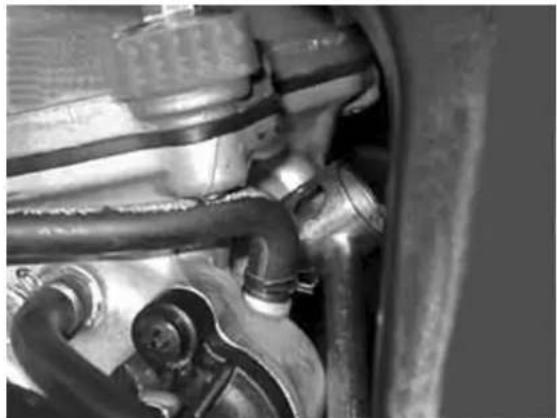
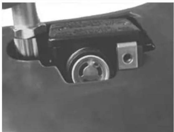
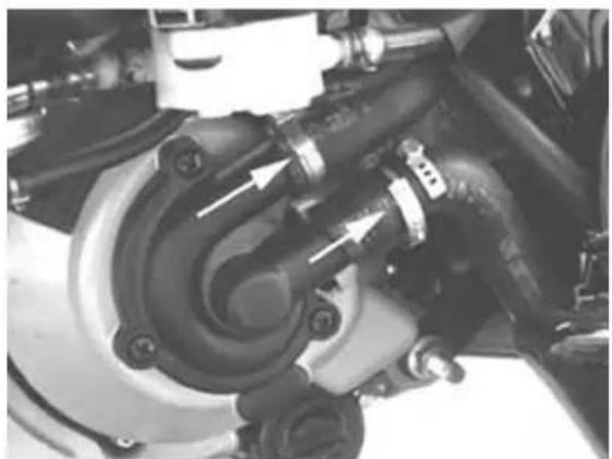
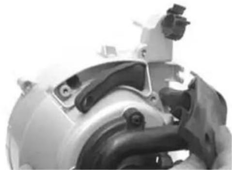
SASBfiltersBinspectionBandBcleaning
The SAS operating system for leader engine
125cc - 200cc Euro 2 is totally similar to the operation of the SAS system for two stroke engine.
The differences are:
instead of entering into the silencer, as it happens in the two stroke system, the secondary air enters directly into the exhaust duct on the head.
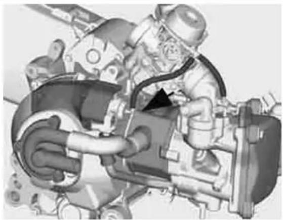
The bleed valve of the 2 stroke engine is replaced
by a membrane. The unit, indicated by an arrow in the figure, is provided with a cut-off connected to the vacuum inlet on the intake manifold to cut off the air inlet during deceleration, to prevent explosions in the silencer.
natural_image
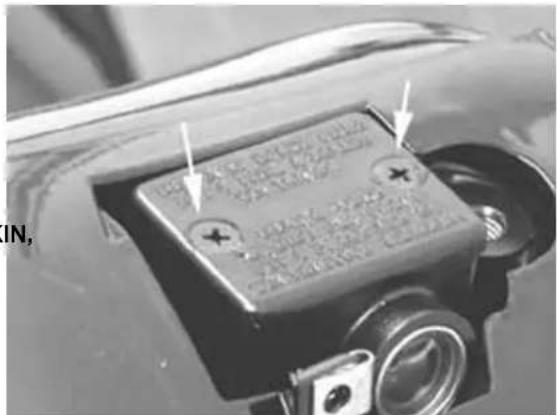
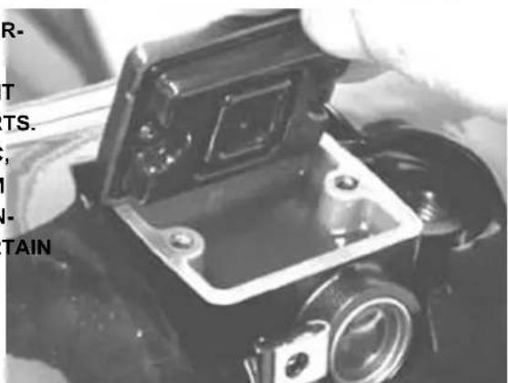
Mechanical assembly diagram showing a worker operating a valve mechanism (no text or labels visible)SystemBdescription:
Air is sucked through hole «A» and it crosses the first filter entering through hole «B»
Through the hole indicated in the figure, air reaches the second filter «B».
At this point, the filtered air enters into the membrane device to be channelled towards the head.
Through a stiff duct flanged to the head, the air reaches the exhaust duct to provide oxygen to unburnt gases before the catalytic converter, thus favouring a better reaction of the latter.
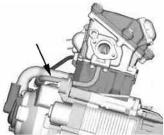
natural_image
Mechanical assembly diagram showing internal components with a black arrow pointing to a specific part (no text or labels visible)- Remove the silencer
- Remove the right side
- Remove the cooling fluid inlet and outlet sleeves from the pump cover. Then, drain the system.
natural_image
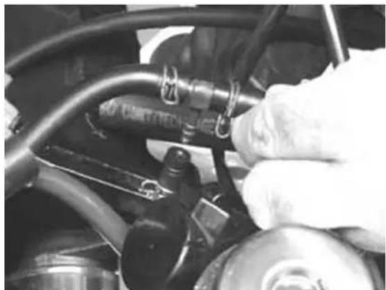
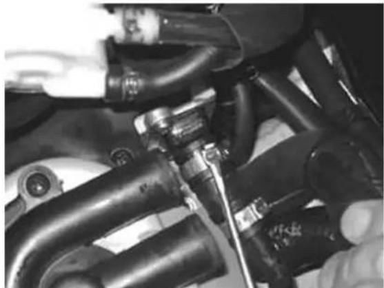
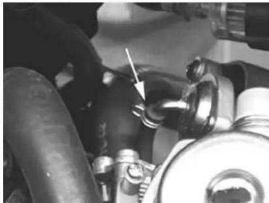
Close-up of a mechanical assembly with hoses and components, no visible text or symbols- Remove the top strip fixing the SAS valve con-
nection sleeve to the drainage as shown in the figure
natural_image
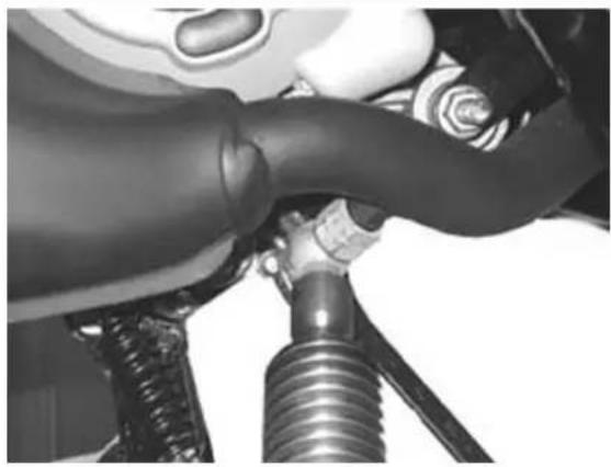
Close-up of mechanical components with hoses and a tool, no visible text or symbols- Remove the 2 fixing screws, the gasket and the pipe connecting the SAS valve to the head. Then, remove the pipe.
natural_image
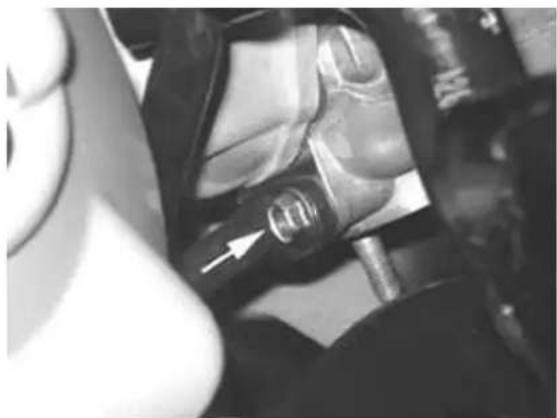
Close-up of a mechanical component with a white arrow pointing to a circular feature (no visible text or symbols)- Release the electric wiring fixing from the fly-wheel cover as shown in the figure
natural_image
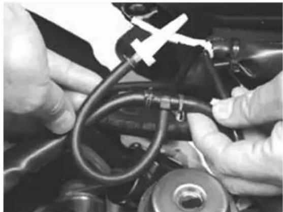
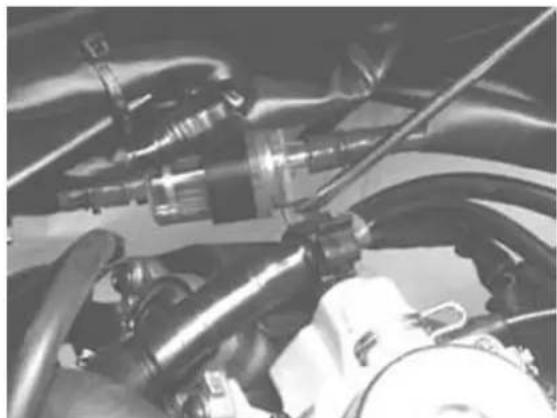
Close-up of mechanical components including hoses and a valve assembly (no visible text or symbols)- Disconnect the vacuum pipe from the SAS valve
natural_image
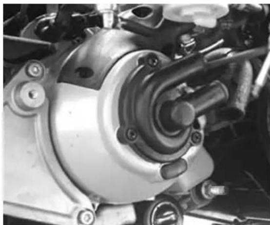
Close-up of mechanical components with a white arrow pointing to a pipe fitting (no visible text or symbols)- Remove the pump support bracket and the fuel filter
- Remove the flywheel cover with the SAS valve by releasing the 4 hexagon screws as shown in the figure
natural_image
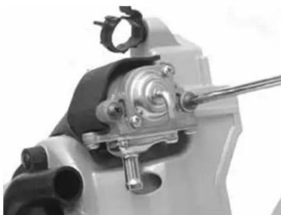
Close-up of a mechanical assembly with visible gears and springs (no text or symbols)- Remove the two SAS valve fixing screws and remove the valve with the O-ring from the support
natural_image
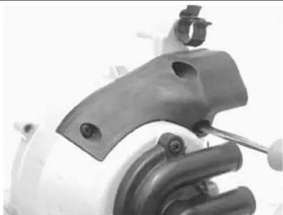
Close-up of a mechanical component with a metallic tool inserted, showing internal gears and shafts (no text or symbols visible)- Remove the plastic support with the gasket
natural_image
Close-up of a car brake caliper with a wrench inserted, no visible text or symbols- Check that the secondary air box valve plastic support is free from cracks and deformations
- Check the integrity of the gasket
- Carefully clean the internal and external filter. If they exhibit damages or abnormal deformations, proceed to the replacement.
- Check that the sleeve connecting the secondary air to the head exhibits no cracks or deformations. Replace them, if necessary
- Check that the metal duct is free from cracks.
CAUTION
LEAKSBFROMBTHEBMATINGBPLANEBBETWEENBSAS VALVEBANDBFLYWHEEL,BRESULTBINBANBINCREASE INBNOISEBEMISSIONSBFROMBTHEBSAS.
natural_image
Close-up of a mechanical component with no visible text or symbols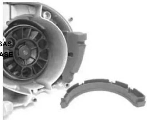
natural_image
Close-up of a mechanical assembly showing internal components and a curved bracket (no visible text or symbols)For re-assembly, perform the operations for removal in the reverse order respecting the orientation of the rubber sleeve connecting the SAS valve to the exhaust system.
INDEXBOFBTOPICS
TROUBLESHOOTINGB
This section provides troubleshooting guidance.
All faults are provided with a list of possible causes and remedies.
Engine
Poor performance
POOR PERFORMANCE
| Possible Cause Operation | |
| Dirty carburettor; feeding pump or vacuum cock failure | Remove, wash with solvent, dry with compressed air or replace |
| Wrong timing or worn timing components | Restore the timing or replace worn parts |
| Clogged silencer,Replace | |
| Air filter clogged or dirty | Remove the sponge, wash with water and shampoo, then impregnate it in a 50% mixture of fuel and specific oil (Selenia Air Filter Oil), then press it without squeezing, let it drip and replace it |
| Automatic starter failure | Check: mechanical sliding, electric connection and presence of power supply, replace if required |
| Engine oil level exceeding the maximum | Check the causes and restore the correct level |
| Low compression: wear of linings, cylinder and valve | Replace worn parts |
| Worn driving belt,Replace | |
| Inefficient automatic transmission | Check the pulley sliding and rollers, replace faulty components, lubricate the mobile driven pulley guide with grease Montblanc Molybdenum Grease |
| Clutch slipping | Check and replace the clutch unit and/or the bell, if required |
| Carburettor jets clogged or dirty | Remove, wash in solvent and dry with compressed air |
Rear wheel spins at idle
REAR WHEEL TURNING WITH IDLE ENGINE
| Possible Cause Operation | |
| Idle rpm too high | Adjust the engine idle speed and the CO, if required. |
| Clutch failure | Check clutch springs / masses |
| Cracked intake union or strips not tightened properly | Replace the intake union and check the strip tightening |
Starting difficulties
START-UP DIFFICULTIES
Possible Cause Operation
| Altered fuel characteristics | Drain altered fuel and refuel |
| Start up speed too low or starter system and motor failure | Check the starter motor, the system and the torque limiter |
| Incorrect valve seal or wrong valve adjustment | Inspect the head and/or set the correct clearance |
| Flooded engine | Start up keeping the gas fully open. If the engine won't start, remove the spark plug, dry it and before replacing it, start the engine to eject the excess of fuel, keeping the cap connected to the spark plug and the latter to earth. If fuel has finished, refuel and start up |
| Automatic starter failure | Check: mechanical sliding, electric connection and presence of power supply, replace if required |
| Air filter clogged or dirty | Remove the sponge, wash with water and shampoo, then impregnate it in a 50% mixture of fuel and specific oil (Selenia Air Filter Oil), then press it without squeezing, let it drip and replace it |
| Faulty spark plug or incorrect ignition advance | Replace the spark plug or check the ignition circuit components |
| Dirty carburettor; feeding pump or vacuum cock failure | Remove, wash with solvent, dry with compressed air or replace |
| Flat battery | Check the battery charge level, in case of traces of sulphation, replace and start the new battery as instructed in section 4-13 |
| Cracked intake union or strips not tightened properly | Replace the intake union and check the strip tightening |
| Defective float valve | Check the proper sliding of the float and the valve efficiency |
| Carburettor nozzles clogged | Remove, wash with solvent, dry with compressed air |
Excessive oil consumption/Exhaust smoke
EXCESSIVE CONSUMPTION
Possible Cause Operation
| Incorrect valve adjustment | Adjust the valve clearance |
| Overheated valves | Remove the head and the valves, grind or replace the valves |
| Valve seat deformed/worn | Replace the head unit |
PossibleBCauseBOperation
| Worn cylinder, worn or broken piston rings | Replace the piston rings or the cylinder unit |
| Worn or broken piston rings, or mounted incorrectly | Replace the piston rings or the cylinder unit |
| Oil leaks from the couplings or from the gaskets | Check and replace the gaskets or restore the coupling seal |
| Worn valve oil guard | Replace the valve oil guard |
| Worn valve guides | Check and replace the head unit if required |
InsufficientBlubricationBpressure
POORBLUBRICATIONBPRESSURE
PossibleBCauseBOperation
| By-Pass remains open. | Check the By-Pass and replace if required. Carefully clean the By-Pass area |
| Oil pump with excessive clearance | Perform the dimensional checks on the oil pump components |
| Oil filter too dirty | Replace the cartridge filter |
| Oil level too low | Restore the level using the recommended oil type (Selenia HI Scooter 4 Tech) |
EngineBtendsBtoBcut-offBatBfullBthrottle
THEBENGINEBTENDSBTOBSTOPBATBMAXBGASBOPENING
PossibleBCauseBOperation
| Low fuel level in float bowl | Restore the level inside the float bowl by bending the petrol inlet thrust plate, so to have, with the carburettor upside-down, the float perfectly flushed with the mating surface of the bowl. |
| Fuel vent pipe clogged | Restore the proper tank aeration |
| Throttle feeding pipes | Restore the proper fuel passage |
| Maximum jet dirty - lean carburetion | Wash with solvent and dry with compressed air |
| Water in the carburettor | Empty the basin by the special drain |
| Incorrect float level | Restore the level in the basin by bending the fuel inlet pin thrusting reed on the float so as to have the float parallel to the basin plane with upturned carburettor |
| Defective feeding circuit | Check the feeding pump, the vacuum inlet, and the duct seal, replace if required |
Engine tends to cut-off at idle
THE ENGINE TENDS TO STOP AT IDLE
Possible Cause Operation
| Calibrated air holes on carburettor obstructed | Remove, wash in solvent and dry with com-pressed air |
| Defective float valve | Check the proper sliding of the float and the valve efficiency |
| Too high level in the basin | Restore the level in the basin by bending the fuel inlet pin thrusting reed on the float so as to have the float parallel to the basin plane with upturned carburettor |
| Automatic starter remains pressed | Check the electric connection, the presence of power and the mechanical sliding; replace, if necessary |
| Air filter clogged or dirty | Remove the sponge, wash with water and shampoo, then impregnate it in a 50% mixture of fuel and specific oil (Selenia Air Filter Oil), then press it without squeezing, let it drip and replace it |
| Wrong timing | Adjust the timing and check the timing components |
| Cut-off device failure | Check the efficiency of the valve, membrane, spring, and the cleaning of the sponge filter |
| Idle adjustment is incorrect | Adjust with the rpm counter |
| Compression end pressure too low | Check the seals of the thermal unit and replace worn components |
| Faulty spark plug or incorrect ignition advance | Replace the spark plug or check the ignition circuit components |
| Starter remains pressed | Check: electric connections, circuit continuity, mechanical sliding, and presence of power; replace, if required |
| Idle nozzle dirty | Wash with solvent and dry with compressed air |
High fuel consumption
HIGH CONSUMPTION
Possible Cause Operation
| Slackened nozzles | Check the maximum and minimum nozzle locking into their seat |
| Fuel pump failure | Check the vacuum duct seal |
| Inefficient starter | Check: electric connections, circuit continuity, mechanical sliding, and presence of power |
| Air filter clogged or dirty | Remove the sponge, wash with water and sham- |
PossibleBCauseBOperation
| poo, then impregnate it in a 50% mixture of fuel and specific oil (Selenia Air Filter Oil), then press it without squeezing, let it drip and replace it | |
| Incorrect float level | Restore the level in the basin by bending the fuel inlet pin thrusting reed on the float so as to have the float parallel to the basin plane with upturned carburettor |
TransmissionBandBbrakes
ClutchBgrabbingBorBperformingBinadequately
CLUTCHBIRREGULARBOPERATIONBORBTEARING
PossibleBCauseBOperation
| Faulty clutch | Check that the masses are free from grease.Check that the contact surface of the clutch masses with the bell is mainly in the centre and with the same features on the three masses.Check that the clutch bell exhibits no abnormal wear or scratches. |
InsufficientBbraking
BRAKINGBSYSTEMBINEFFICIENCY
PossibleBCauseBOperation
| Fluid leaks from the hydraulic braking system | Check the pad wear (1.5 mm MIN).Make sure the brake disc is not worn, scratched or deformed.Make sure the fluid level in the pump is correct and change the brake fluid if necessary.Make sure there is no air in the circuit and bleed if necessary.Make sure the front brake caliper moves in line with the disc. |
| Coolant leaking from the hydraulic brake circuit | Flexible connections, piston or brake pump gaskets faulty. Replace |
| Brake disc slackened or deformed | Check the tightening of the brake disc screws; measure the disc axial deviation using a comparator and keeping the wheel mounted on the vehicle |
BrakesBoverheating
BRAKEBOVERHEATING
PossibleBCauseBOperation
| Pistons defective sliding | Check caliper, renew any damaged part |
| Disco freno allentato o deformato | Verificare il bloccaggio delle viti disco freno; misurare con un comparatore ed a ruota montata sul veicolo, lo scostamento assiale del disco. |
| Fori di compensazione sulla pompa otturati | Pulire accuratamente e soffiare con aria compressa. |
| Guarnizioni in gomma rigonfiate o incollate | Sostituire le guarnizioni. |
ElectricalBsystem
Battery
BATTERY
PossibleBCauseBOperation
| Battery | This is the system device that requires the most assiduous surveillance and the most diligent maintenance.If the vehicle is not used for a certain period (1 month and more), the battery needs periodical re-charging. The battery tends to go completely flat within around 3 months. When reinstalling the battery on the motor cycle, be careful not to invert connections, considering that the black earth wire must be connected to the negative terminal, whereas the other red wire must be connected to the terminal marked with + sign. |
TurnBsignalBlightsBmalfunction
FLASHINGBLIGHTSBNOTBWORKING
PossibleBCauseBOperation
| Electronic ignition device failure. | With the key switch set to «ON» connect the jumpers 1 (Blue-Black) and 5 (Red/Blue) on the control unit connector.If lights do not turn on and remain solid when the flashing light control is actuated, replace the control unit, otherwise check the wiring and the switch. |
SteeringBandBsuspensions
HeavyBsteering
HARDENING STEERING
Possible Cause Operation
| Excessive steering wheel clearance | Check the tightening of the top and bottom ring nut. If the anomaly continues during the steering wheel rotation even after the adjustment, check the bearing ball rolling seats. If they are recessed or if the balls are squashed, replace. |
Excessive steering play
EXCESSIVE STEERING WHEEL CLEARANCE
Possible Cause Operation
| Steering wheel difficult to operate | Check the tightening of the top and bottom ring nut. If the anomaly continues during the steering wheel rotation even after the adjustment, check the bearing ball rolling seats. If they are recessed or if the balls are squashed, replace. |
Noisy suspension
NOISY SUSPENSION
Possible Cause Operation
| Noisy suspension | If the front suspension is noisy, check: the front shock absorber efficacy, the condition of the ball bearings and the relevant locking nuts; the travel end rubber pads and the sliding bushes. Finally, check the tightening torques of the wheel hub, brake caliper, disc and shock absorber in the connection to the hub and to the steering tube. |
Suspension oil leakage
SUSPENSION OIL LEAKING
Possible Cause Operation
| Suspension oil leaking | Replace the shock absorber. Check the wear of the steering wheel caps and the adjustments. |
INDEX OF TOPICS
ELECTRICAL SYSTEM
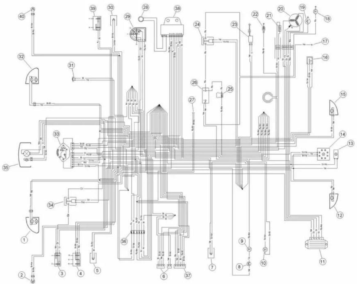
ELECTRICAL SYSTEM
Specification Desc./Quantity
| 1 | Front left-hand direction indicator with 2 bulbs |
| 2 | Rear stop light switch |
| 3 | Light switch with flash |
| 4 | Turn signal switch |
| 5 | Horn button |
| 6 | Intercom fitting |
| 7 | Saddle opening button |
| 8 | Thermal switch |
| 9 | Electric fan |
| 10 | Saddle opening actuator |
| 11 | Voltage regulator |
| 12 | Rear left-hand direction indicator with bulb |
| 13 | Number plate light with bulb |
| 14 | Complete tail light with position light with 8 |
Specification Desc./Quantity
| stop bulbs | |
| 15 | Rear right-hand direction indicator with bulb |
| 16,Fuel level thermistor | |
| 17,Engine earth | |
| 18,Starter motor | |
| 19,Oil pressure sensor | |
| 20,Flywheel magneto | |
| 21,Automatic starter | |
| 22,Thermistor | |
| 23,H.V. coil | |
| 24,Starter relay | |
| 25,Fuse holder with 2 fuses | |
| 26,Battery,12V - 4Ah | |
| 27,Anti-theft alarm fitting | |
| 28,Immobiliser antenna | |
| 29,Ignition key-switch | |
| 30 | Starter button |
| 31 | Horn |
| 32 | Front right-hand direction indicator with 2 bulbs |
| 33 | Instrument group with 9 bulbs, warning lights, fuel reserve warning light, oil pressure warning light, upper beam indicator, RH flashing light indicator, LH flashing light indicator, LED for immobilizer, 3 bulbs for instrument illumination |
| 34 | Remote control switch |
| 35 | Complete right or left-hand asymmetric headlight with bulb for headlight and 1 bulb for position |
| 36 | Fuse holder box |
| 37,Anti-theft alarm fitting | |
| 38 | Control device ignition |
| 39 | Engine stop deviator |
| 40 | Front brake stop light switch |
Colour coding
Ar: Orange Az: Light blue Bi: White BI: Blue Gi: Yellow Gr: Grey
Ma:Brown Ne: Black Ro: Pink Rs: Red Ve: Green Vi: Purple
ConceptualBdiagrams
Ignition
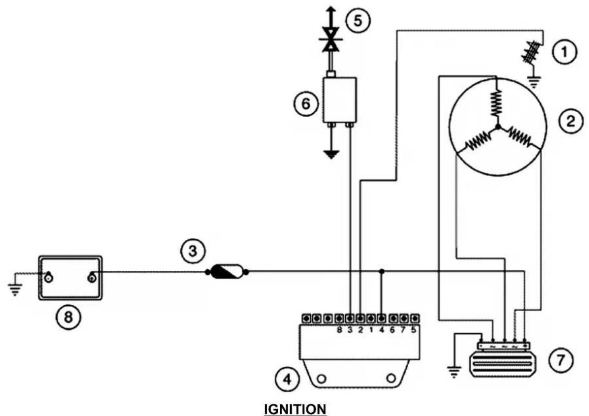
SpecificationBDesc./Quantity
| 1,Pick - up |
| 2,Magneto flywheel |
| 3,Fuse 15A (No. 7) |
| 4,Control device ignition |
| 5,Spark plug |
| 6,H.V. coil |
| 7,Voltage regulator |
| 8,Battery,12V-12Ah |
H.T.Bcoil
This is to inform you that, starting from frame no. ZAPM3120000022142, a protective cap has been introduced for the H.T. coil cable; this is aimed at preventing the cable from rubbing against other
components.
HeadlightsBandBautomaticBstarterBsection
HEADLIGHTSBANDBAUTOMATIC STARTER
SpecificationBDesc./Quantity
| 1,Remote control switch | |
| 2,Light switch with flash | |
| 3,Dipped beam/upper bulb | 12V-55/60W |
| 4,Upper beam indicator,12V-1,2W | |
| 5,No. 3 bulbs for instrument lighting + side/ taillights indicator | 12V-2W |
| 6,No. 3 number plate position bulbs | 12V - 5W |
| 7,Fuse,8A | |
| 8,Heater control device | |
| 9,Automatic starter | |
| 10,Fuse,15 A | |
| 11,Battery | 12V-12Ah |
| 12 Electronic ignition device | |
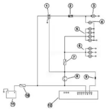
flowchart
graph TD
    1 --> 2
    2 --> 3
    3 --> 4
    4 --> 5
    5 --> 6
    6 --> 7
    7 --> 8
    8 --> 9
    9 --> 10
    10 --> 11
    11 --> 12
    12 --> 13
    13 --> 14
    14 --> 15
    15 --> 16
    16 --> 17
    17 --> 18
    18 --> 19
    19 --> 20
    20 --> 21
    21 --> 22
    22 --> 23
    23 --> 24
    24 --> 25
    25 --> 26
    26 --> 27
    27 --> 28
    28 --> 29
    29 --> 30
    30 --> 31
    31 --> 32
    32 --> 33
    33 --> 34
    34 --> 35
    35 --> 36
    36 --> 37
    37 --> 38
    38 --> 39
    39 --> 40
    40 --> 41
    41 --> 42
    42 --> 43
    43 --> 44
    44 --> 45
    45 --> 46
    46 --> 47
    47 --> 48
    48 --> 49
    49 --> 50
    50 --> 51
    51 --> 52
    52 --> 53
    53 --> 54
    54 --> 55
    55 --> 56
    56 --> 57
    57 --> 58
    58 --> 59
    59 --> 60
    60 --> 61
    61 --> 62
    62 --> 63
    63 --> 64
    64 --> 65
    65 --> 66
    66 --> 67
    67 --> 68
    68 --> 69
    69 --> 70
    70 --> 71
    71 --> 72
    72 --> 73
    73 --> 74
    74 --> 75
    75 --> 76
    76 --> 77
    77 --> 78
    78 --> 79
    79 --> 80
BatteryBrechargeBandBstarting
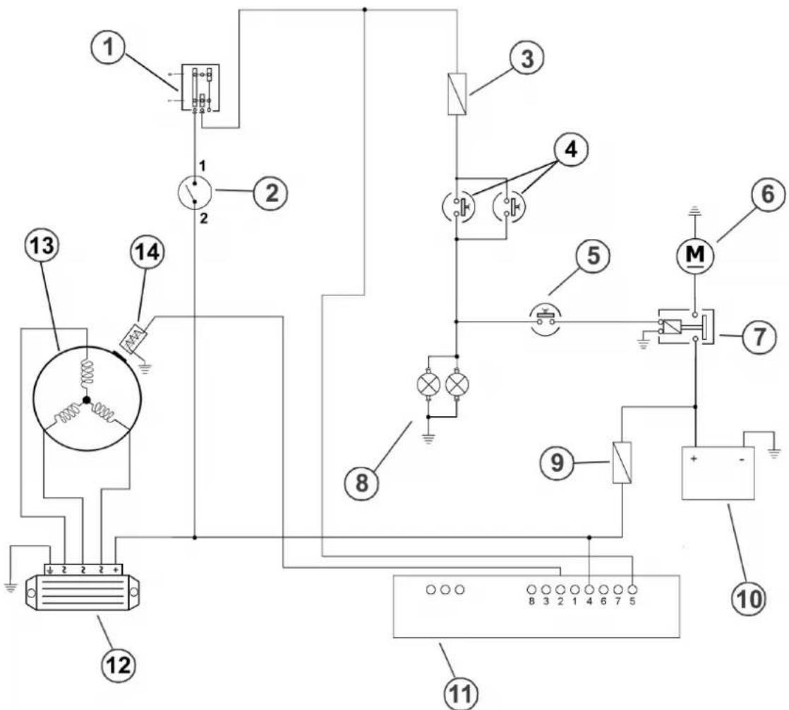
BATTERYBRECHARGEBANDBSTART-UP
SpecificationBDesc./Quantity
| 1,Engine stop deviator | ||
| 2,Key switch contacts | ||
| 3,Fuse,5A | ||
| 4,Stop buttons | ||
| 5,Start up button | ||
| 6,Starter motor | ||
| 7,Remote starter switch | ||
| 8 | No. 8 bulbs for stop light | 12V-2,3W |
| 9,Fuse,15 A | ||
| 10,Electronic ignition | ||
| 11,Battery,12V-12Ah | ||
| 12,Electronic ignition device | ||
| 13 | Voltage regulator | |
SpecificationBDesc./Quantity
| 14,Magneto flywheel |
| 15,Pick - up |
LevelBindicatorsBandBenableBsignalsBsection
LEVELBINDICATORSBANDBENABLEBSIG-
NALS
SpecificationBDesc./Quantity
| 1,Cooling fluid temperature indicator | ||
| 2,Fuel level gauge | ||
| 3,Fuel level thermistor | ||
| 4,Thermistor | ||
| 5,Fuel indicator,12V - 1.2W | ||
| 6,Low oil pressure warning light | 12V - 2W | |
| 7 | Oil pressure sensor | |
| 8 | Fuse | 7,5A |
| 9 | Heater control device | |
| 10 | Battery | 12V-12Ah |
| 11 | Fuse | 15 A |
| 12 | Electronic ignition device | |
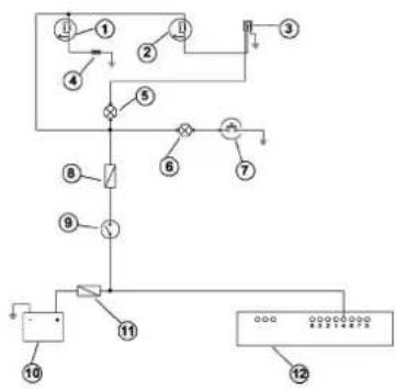
flowchart
graph TD
    1["①"] --> 2["②"]
    2 --> 3["③"]
    3 --> 4["④"]
    4 --> 5["⑤"]
    5 --> 6["⑥"]
    6 --> 7["⑦"]
    7 --> 8["⑧"]
    8 --> 9["⑨"]
    9 --> 10["⑩"]
    10 --> 11["⑪"]
    11 --> 12["⑫"]
    11 --> 12
    12 --> 12
    style 1 fill:#f9f,stroke:#333
    style 2 fill:#f9f,stroke:#333
    style 3 fill:#f9f,stroke:#333
    style 4 fill:#f9f,stroke:#333
    style 5 fill:#f9f,stroke:#333
    style 6 fill:#f9f,stroke:#333
    style 7 fill:#f9f,stroke:#333
    style 8 fill:#f9f,stroke:#333
    style 9 fill:#f9f,stroke:#333
    style 10 fill:#f9f,stroke:#333
    style 11 fill:#f9f,stroke:#333
    style 12 fill:#f9f,stroke:#333
TurnBsignalBlights
DIRECTIONBINDICATORS
SpecificationBDesc./Quantity
| 1 | Direction indicators | 12V- 2W |
| 2 | 4 Turn indicator bulbs | 12V-10W |
| 3 | No. 2 rear flashing light bulbs | 12V - 10W |
| 4 | Horn | 12V |
| 5 | Saddle opening button | |
| 6 | Horn button | |
| 7 | Turn signal switch | |
| 8 | Saddle opening actu- |
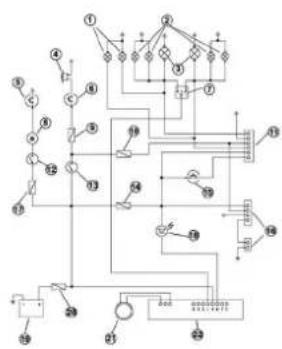
flowchart
graph TD
    A["①"] --> B["②"]
    B --> C["③"]
    C --> D["④"]
    D --> E["⑤"]
    E --> F["⑥"]
    F --> G["⑦"]
    G --> H["⑧"]
    H --> I["⑨"]
    I --> J["⑩"]
    J --> K["⑪"]
    K --> L["⑫"]
    L --> M["⑬"]
    M --> N["⑭"]
    N --> O["⑮"]
    O --> P["⑯"]
    P --> Q["⑰"]
    Q --> R["⑱"]
    R --> S["⑲"]
    S --> T["⑳"]
    T --> U["㉑"]
    U --> V["㉒"]
    V --> W["㉓"]
    W --> X["㉔"]
    X --> Y["㉕"]
    Y --> Z["㉖"]
    Z --> AA["㉗"]
    AA --> AB["㉘"]
    AB --> AC["㉙"]
    AC --> AD["㉚"]
    AD --> AE["㉛"]
    AE --> AF["㉜"]
    AF --> AG["㉝"]
Specification Desc./Quantity
| ator |
| 9,Fuse,7.5A |
| 10,Fuse,7,5A |
| 11,Anti-theft alarm fitting |
| 12,Heater control device |
| 13,Key switch contacts |
| 14,Fuse,7,5A |
| 15,Anti-theft alarm fitting |
| 16,Intercom fitting |
| 17,Fuse,10A |
| 18,Immobilizer LED |
| 19,Battery,12V-12Ah |
| 20,Fuse,15 A |
| 21,Immobiliser antenna |
| 22,Electronic ignition device |
Checks and inspections
This section is dedicated to the controls on the electric system components.
Immobiliser
The electronic ignition system is realised with direct current power supply and is equipped with immobilizer antitheft device built in the control unit.
The ignition system is made up of:
- control unit
- immobilizer antenna
- master and service key with built-in transponder
- H.V. coil
- diagnostic LED
The diagnostic LED also has the function of deterrent flashing. This function is obtained every time the key switch is set to «OFF» or if the emergency stop switch is set to «OFF» and it stays on
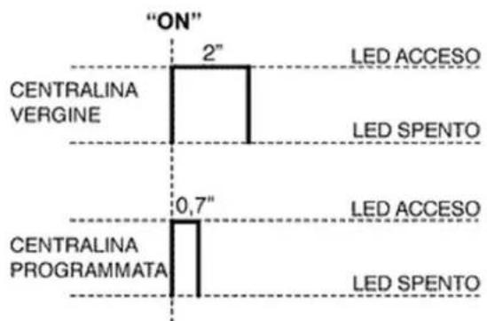
other
| System | Time Period | Color | | --- | --- | --- | | CENTRALINA VERGINE | 2" | Light Blue | | CENTRALINA PROGRAMMATA | 0.7" | Dark Blue | | LED ACCESO | - | Light Blue | | LED SPENTO | - | Dark Blue |for 48 hours to avoid discharging the battery.
When the key switch is set to «ON» the deterrent flash stops and there is a confirmation flash of the switching to «ON».
This flash lasts according to the control unit programming (see figure). If the led stays off even when switching to «ON», proceed to the following checks:
- battery voltage presence
- main fuse 15A (No 7) efficiency
If the led remains off, check the control unit power supply as follows:
- Disconnect the control unit connector and check the following conditions:
- Presence of battery voltage between terminal no. 4 (Red/Black) and earth
- Presence of battery voltage between terminal no. 4 (Red/Black) and no. 8 (Negative) as shown in the figure.- Presence of battery voltage between terminal no. 5 and no. 8 with the key switch set to «ON», the side stand raised and the emergency stop switch set to «RUN».
If no faults are found, replace the control unit; otherwise, check the wiring and the following components:
- Engine stop remote control switch;
- Emergency stop switch;
- Side stand switch;
- Key switch contacts.
Virgin circuit
When the ignition system is not coded, it allows
the engine operation but with a limit of 2,000 rpm;
miss is evident when trying to accelerate
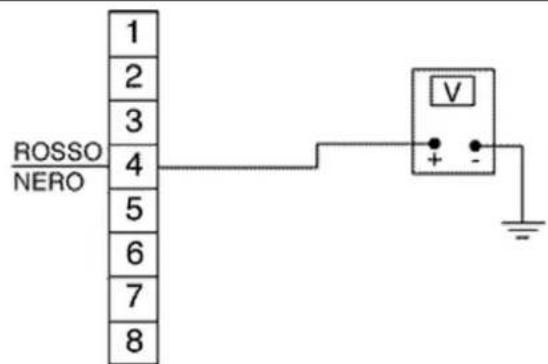
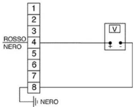
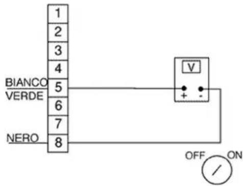
To code the system, besides having the side stand raised and the emergency stop switch set to «RUN» it is necessary to use the MASTER (brown) and SERVICE keys (black) as follows:
- Insert the MASTER key, set to «ON» and keep this position for 2 seconds (limit values: 1 - 3 seconds).
- Alternately introduce all black keys available switching each key to «ON» for 2 seconds.
- Insert the MASTER key again and set to «ON» for 2 seconds.
The maximum time to change keys is of 10 seconds.
Three service keys (Black coloured) can be programmed within the same storage operation.
Sequence and times must be respected; otherwise, repeat the procedures from the beginning. Once the control unit has been coded, an inseparable matching between control unit and the transponder of the MASTER key is created. This matching allows performing further service key storage in case of loss, replacement, etc.
Each storage deletes the former one. In case of loss of the service key storage, carefully check the high voltage system shielding: In any case it is advisable to use resistive spark plugs.
Characteristic
Shielded cap resistance
\~ 5000 Ω.
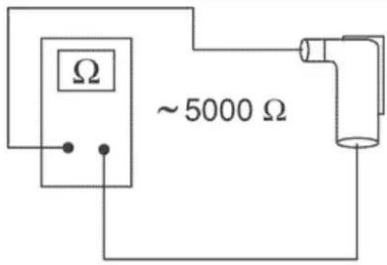
Diagnostic codes
After the confirmation flash of the switching to «ON» there may follow a warning of coded failures. This occurs with LED off for 2 seconds, after which diagnostic codes are transmitted with 0.5 second flashes.
After the failure code signal, the LED turns on with solid light to indicate that start up is not possible; see the graph:
2 FLASH CODE - Example electronic control unit programmed, transponder absent and/or aerial malfunctioning. Ignition disabled - Vehicle immobilised
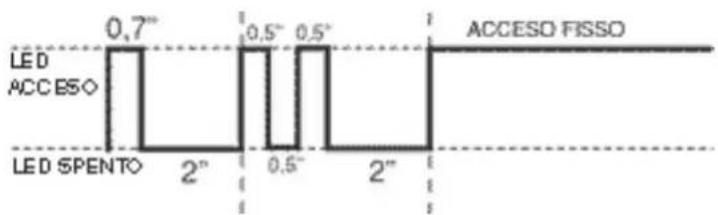
other
| Time Period | State | Value | |-------------|-------------|-------| | 0.7 | LED ACCESO | 0.7 | | 0.5 | LED SPENTO | 0.5 | | 2 | LED ACCESO | 0.5 | | 2 | LED SPENTO | 2 | | 2 | LED ACCESO | 0.5 | | 2 | LED SPENTO | 2 | | 2 | LED ACCESO | 0.5 | | 2 | LED SPENTO | 0.5 | | 2 | LED ACCESO | 0.5 | | 2 | LED SPENTO | 0.5 | | 2 | LED ACCESO | 0.5 | | 2 | LED SPENTO | 0.5 | | 2 | LED ACCESO | 0.5 | | 2 | LED SPENTO | 0 | | 2 | LED ACCESO | 0.5 | | 2 | LED SPENTO | 0.5 | | 2 | LED ACCESO | 0.5 | | 2 | LED SPENTO | 0.5 | | 2 | LED ACCESO | 0.5 | | 2 | LED SPENTO | 0 | | 2 | LED ACCESO | 0.5 | | 2 | LED SPENTO | 0.5 | | 2 | LED ACCESO | 0.5 | | 2 | LED SPENTO | 0.5 | | 2 | LED ACCESO | 0.5 | | 2 | LED SPENTO | 1 | | 2 | LED ACCESO | 1 | | 2 | LED SPENTO | 1 | | 2 | LED ACCESO | 1 | | 2 | LED SPENTO | 1 | | 2 | LED ACCESO | 1 | | 2 | LED SPENTO | 1 | | 2 | LED ACCESO | 1 | | 2 | LED SPENT0 | - | | 2 | LED ACCESO | - | | 2 | LED SPENT0 | - | | 2 | LED ACCESO | - | | 2 | LED SPENT0 | - | | 2 | LED ACCESO | - | | 2 | LED SPENT0 | - | | 2 | LED ACCESO | - | | 2 | LED SPENT0 | - |3 FLASH CODE - Example electronic control unit programmed, aerial in working condition and transponder code unknown. Ignition disabled - Vehicle immobilised
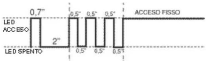
other
| Time Interval | LED SpentO | ACCESO FISSO | | ------------- | ---------- | ------------ | | 0.7" | 2" | | | 0.5" | | 0.5" | | 0.5" | | 0.5" | | 0.5" | | 0.5" |DiagnosticBcodeB-B2Bflashes
Diagnostic code: 2 flashes
Detecting the 2-flash code, proceed with the following checks:
- Check whether or not the anomaly persists when changing key (including MASTER). If the anomaly is present with any key, disconnect the power plant antenna connector and check the continuity of the antenna using the multimeter 020331Y.
In case of non-compliant values, replace the antenna.
Replace the power plant if you do not find anomalies on the antenna.
CAUTION
BEFOREBSTORINGBTHEBDATABONBTHEBNEWBPOWERBPLANT,BCHECKBTHATBNOBANOMALYBCODEBISBINDICATED.BTHISBISBNECESSARYBSOBTHATBYOUBDOBNOTBPOINTLESSLYBWASTEBABNEWBPOWERBPLANT
ElectricBcharacteristic
ImmobolizerBantenna
\~ 7 ÷ 9 ohm
DiagnosticBcodeB-B3Bflashes
If the 3 flash code is displayed, check if the fault occurs also when introducing the MASTER key in
the key switch.
- If the fault does not occur with the MASTER key, proceed to a new coding of the service keys (blue).
- If the fault continues, this means that the MAS-TER key and the control unit are not matched; in this case, the control unit must be replaced and the keys must be coded again.
The immobilizer system is efficient when after switching to «ON», a flash of 0.7 seconds occurs only (see graph).
In this case, ignition is possible. Example with programmed control unit, transponder present, programmed key and working antenna
Ignition is enabled (normal use conditions)

line
| Position | Value | |---|---| | LED ACCESS | 0.7° | | LED SPENTO | 2° | | NESSUN LAMPEGGIO | (not labeled) | | SPENTO FISSO | (not labeled) |Ignition circuit
Once the immobilizer system has been enabled, it is possible to have the spark at the spark plug by the H.V. coil and the signals coming from the Pick-Up.
The basic power supply comes from the battery, the system is calibrated in such a way that any drops of voltage of the battery are perceived by the start up system but are unimportant for the start up system.
The Pick-Up is connected to the control unit by a single wire, thus for the earth circuit the Pick-Up is connected to the control unit by the chassis and the engine earth cable.
To prevent troubles to the start up system during start up, it is very important to have a good efficiency of the engine-chassis earth connection.
Spark plug
Disconnect the control unit connector and check the continuity between the terminal no. 2 (green) and no. 8 (black). The Pick-Up should be as follows:
Electric characteristic
Resistance value pick-up
Resistance value pick-up: 105 ÷ 124 ohm
In case of circuit interruption, repeat the check between the flywheel connector and the engine earth (see engine manual). If non-conforming values are detected, replace the Pick-up, or fix the wiring.
If conforming values are detected, try to replace the control unit (without programming it) and ensure that the problem has been fixed by checking the presence of the spark at the spark plug; after that, program the control unit.
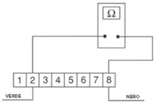
- H.V. coil primary check
Disconnect the control unit connector and check the continuity between the terminal no. 3 and no. 8 (see figure).
If non-conforming values are detected, repeat the check directly at the positive and negative terminals of the H.V. coil primary.
If conforming values are detected, fix the wiring or replace the H.V. coil.
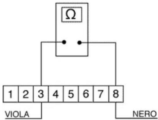
N.B.
THEBMULTIMETERBMUSTBBEBSETBTOBMEASURE DIRECTBVOLTAGE.
ElectricBcharacteristic
ResistanceBvalue:
$$ 0, 4 \div 0, 5 \text { Ohm } $$
- H.V. coil secondary check
Disconnect the spark plug cap from the H.V. cable and measure the resistance between the end of the H.V. cable and the negative of the H.V. coil (see figure).
If non-conforming values are detected, replace the H.V. coil. For a more complete diagnosis, it is possible to check the peak voltage using the mul-
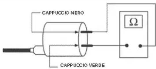
timeter adapter.
SpecificBtooling
020409YBMultimeterBadapterB(PeakBvoltage measurement)
ElectricBcharacteristic
ResistanceBvalue:
\~ 3000 ± 300 Ohm
- Pick-Up
Disconnect the control unit connector and connect the positive terminal to connector no. 2 and the negative to connector no. 8 (see figure). Make the engine rotate by the start up system and check the voltage generated by the Pick-Up. In case of non-conforming values, replace the Pick-Up.
N.B.
THEBMULTIMETERBMUSTBBEBSETBTOBMEASURE DIRECTBVOLTAGE.
ElectricBcharacteristic
VoltageBvalue:
2 Volt
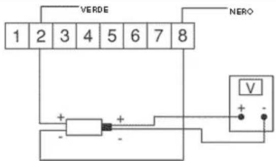
- H.V. coil
With control unit and H.V. coil normally connected, measure the voltage of the coil primary during the start up test by the adapter for peak voltages inserting the positive terminal to earth and the negative to the positive connector of the coil.
In case of non-conforming values, replace the control unit.
N.B.
THEBPLASTICBCAPBOFBTHEBPOSITIVEBTERMINAL OFBTHEBPRIMARYBOFBTHEBH.V.BCOILBISBIDENTIFIED
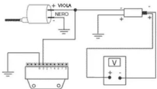
BYBTHEBBLACKBCOLOUR,BTHEBNEGATIVEBONEBIS IDENTIFIEDBBYBTHEBGREENBCOLOUR.
ElectricBcharacteristic
VoltageBvalue:
100 Volt
BatteryBrechargeBcircuit
The charging circuit consists of tri-phase generator and a flywheel magneto.
The generator is connected to the voltage regulator.
This is then connected to the positive pole of the battery (via the 15A fuse) and earth.
This system does not therefore feature any connection to the key-switch.
The tri-phase generator allows for remarkable recharging power and allows to reach a good compromise between output power and stability at idle.
For this reason is necessary that the idle is adjusted as prescribed.
SpecificBtooling
020333YBSingleBbatteryBcharger
020334YBMultipleBbatteryBcharger
StatorBcheck
Disconnect the connector from the voltage regulator and check the presence of continuity between each yellow wire with the other two.
ElectricBcharacteristic
StatorBcheckB1
Ohm value: 0,7 ÷ 0,9 Ohm
Also check that each yellow wire is insulated from earth.
If non-conforming values are detected, repeat the checks directly on the stator; in case of further
wrong values, replace the stator or fix the wiring.
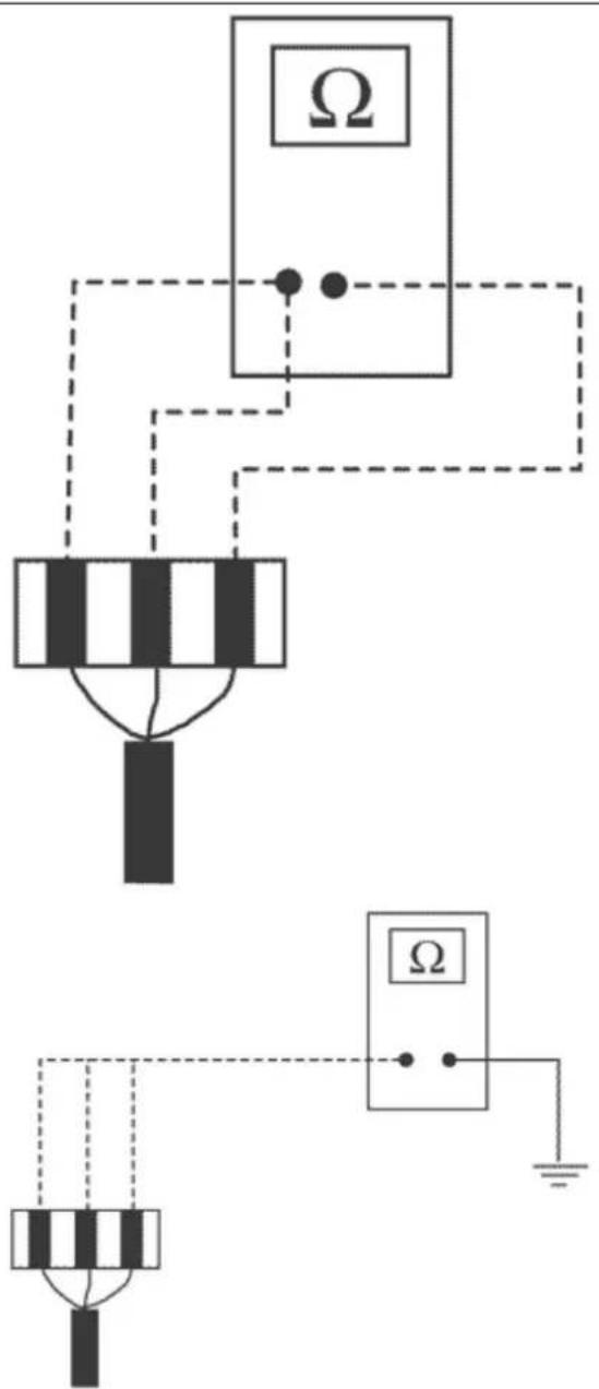
- Use the tester to check the continuity between connections 5-3 and 5-1.
- Check the earth insulation on the three phases of the stator 5-earth, 3-earth, 1-earth. Approximate resistance of each phase: 0.7 - 0.9 Ω
Minimum oil pressure switch check - Use the tester to check the continuity between connection 4 and earth (with engine off).
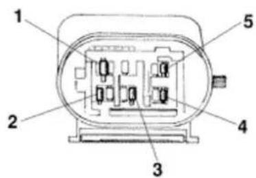
Pick-Up Check
- Check that between connection 2 and earth there is a resistance of about 105 - 124 at 20^
C.
- In case of different values, replace the defective parts.
N.B.
THEBVALUESBAREBSTATEDBFORBAMBIENTBTEMPERATURE.BCHECKINGBWITHBTHEBSTATORBIN WORKINGBTEMPERATUREBLEADSBTOBVALUES HIGHERBTHANBTHOSEBSTATED.
VoltageBregulatorBcheck
With battery fully charged and lights off, measure the voltage at the battery poles with engine at high speed.
Voltage should not exceed 15.2 Volt.
In case of higher voltage, replace the regulator. If voltage is less than 14 Volt, check the stator and its wiring.
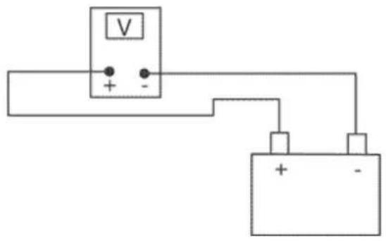
RechargeBsystemBvoltageBcheck
Connect the induction collet of an amperometer to the positive cable of the voltage regulator, measure the battery voltage and turn off the lights of the vehicle with engine off, then wait until voltage settles at about 12 Volt. Start the engine and measure the current delivered by the system with lights on and engine at high speed.
If the delivered current value is less than 10A, repeat the test using a new regulator and/or stator.
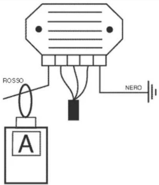
Choke Inspection
For the component resistive and functional check, see the engine section. As regards its power supply, keep the system connector connected and check the presence of battery voltage at the two terminals with engine running (see figure).
If there is no voltage, connect the multimeter negative terminal to earth and the positive terminal to the orange wire of the automatic starter device; with key switch set to «ON» check the presence of battery voltage; in case of negative result, check the wiring to the key switch and the functionality of the 15° fuse (N° 8). If voltage is present, repeat the check from the ignition control unit connector.
After disconnecting the starter, start the engine and keep it idle then check the presence of voltage connecting the multimeter with positive terminal to the terminal no. 5 (light blue) and negative to terminal no. 7 (white-black) (see figure). If there is no voltage, replace the control unit after checking the integrity of the fuses; otherwise, check the wiring between starter and control unit, or finally, as last option replace the starter.
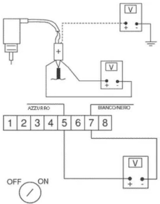
Turn signals system check
If the direction indicators are not working, proceed as follows:
- Disconnect the control unit connector and check that between terminal no. 4 (red/black) and earth there is battery voltage.
- Check the voltage is present between terminal no. 4 and terminal no. 8 (black).
- Repeat the check between terminal no. 5 (light blue) and terminal no. 8 (black) with the key switch set to «ON», and emergency switch set to «RUN».
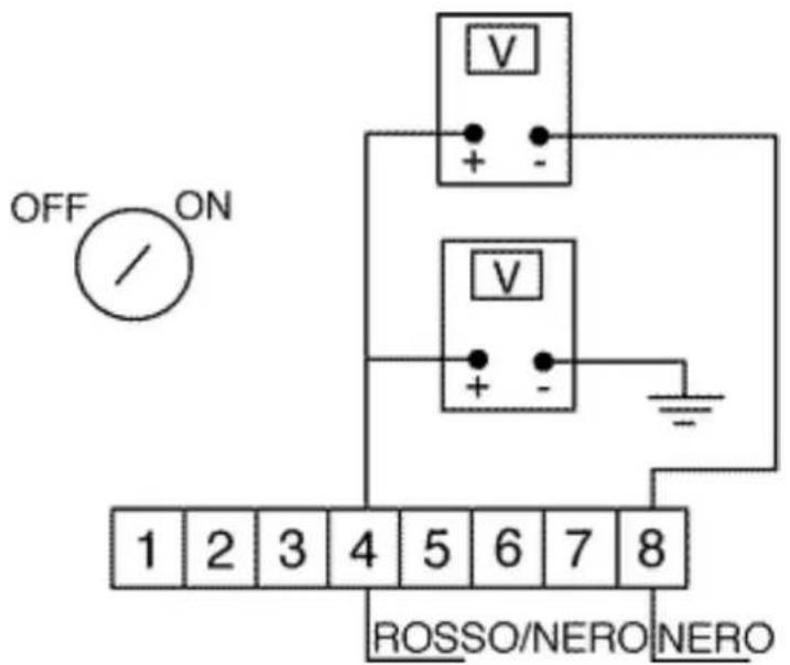
If no voltage is detected, check the wiring, the connections and the integrity of the main 15° fuse, otherwise proceed as follows:
- Connect the jumper terminals no. 1 (black/blue) and no. 4 (red/black) (see figure) and actuate the flashing light switch alternately to the right and to the left, and check that lights turn on.
If this occurs, replace the control unit since it is defective.
If this does not occur, check the control unit - flashing light switch connections, then repeat the test. If the wiring is not defective and the flashing lights still are not working, replace the switch as it is defective.
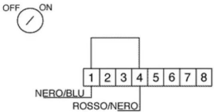
Fuses
The electric system is equipped with:
-
six protection fuses «A» located inside the trunk compartment on the left;
-
a 15 A fuse «B» placed under the helmet compartment under the saddle hinge catch
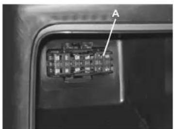
The table shows the features of the fuses on the vehicle.
CAUTION
BEFOREBREPLACINGBTHEBBLOWNBFUSE, TRYBTOBELIMINATEBTHEBFAULTBTHATBHAS CAUSEDBITBTOBBLOW.
NEVERBTRYBTOBREPLACEBABFUSEBUSINGBDIFFERENTBMATERIALB(FORBEXAMPLEBABPIECE OFBELECTRICBWIRE)BORBABFUSEBWITHBHIGHERBAMPERAGE.
FUSES
SpecificationBDesc./Quantity
| 1,Rear side/taillight,number plate holder,instrument lightingand instrument lightindicator. | OrderBonBterminalholder: 1Fuse: 5AProtectedBcircuits:Rear side/taillight,number plate holder,instrument lightingand instrument lightindicator. |
| 2,Stop light bulb, remote control startswitch enable signal | OrderBonBterminalholder: 2Fuse: 5AProtectedBcircuits:Stop light bulb, remote control startswitch enable signal |
| 3,Intercom fitting, anti-theft fitting, watertemperature indicator, fuel reserve indicator, oil pressure indicator and fuel reserve light | OrderBonBterminalholder: 3Fuse: 7,5AProtectedBcircuits:Intercom fitting, anti-theft fitting, watertemperature indicator, fuel reserve indicator, oil pressure indicator and fuel reserve light |
| 4,Horn,OrderBonBterminal | holder: 4Fuse: 7,5AProtectedBcircuits:Horn |
| 5,Intercom fitting, anti-theft fitting, immobil- | OrderBonBterminalholder: 5 |
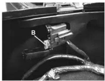
natural_image
Close-up of a mechanical component with labeled part B, showing wiring and tubing (no readable text or symbols)SpecificationBDesc./Quantity
| izer led | Fuse:B7,5AProtectedBcircuits:Intercom fitting, anti-theft fitting, immobilizer led |
| 6,Electric saddle opener, dipped/full headlights, full headlight indication light | OrderBonBterminal holder: 6Fuse:B10AProtectedBcircuits:Electric saddle opener, dipped/full headlights, full headlight indication light |
7, General, OrderBonBterminal
holder: 7
Fuse:B15A
ProtectedBcircuits:
General
Dashboard
A = Digital clock with calendar
B = Coolant temperature indicator
C = RH direction indicator switch
DB= Fuel level indicator
EB= Light indicator
FB= Upper beam indicator
G = Low oil pressure indicator
HB= Fuel reserve indicator
IB= Tachometer
LB= Odometer
M = Left direction indicator
N = Alarm led (immobilizer)
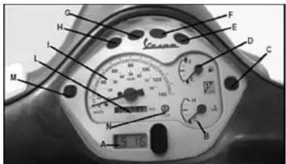
A
SpecificationBDesc./Quantity
| 1,Fuel level indicator signal |
| 2,Low-beam warning light |
| 3,Oil indicator |
| 4,Power supply (+) |
SpecificationBDesc./Quantity
| 5,Low fuel warning light |
| 6,Lighting |
B
SpecificationBDesc./Quantity
| 1,Earth |
| 2,Left turn signal light |
| 3,Right turn signal light |
| 4,Temperature signal |
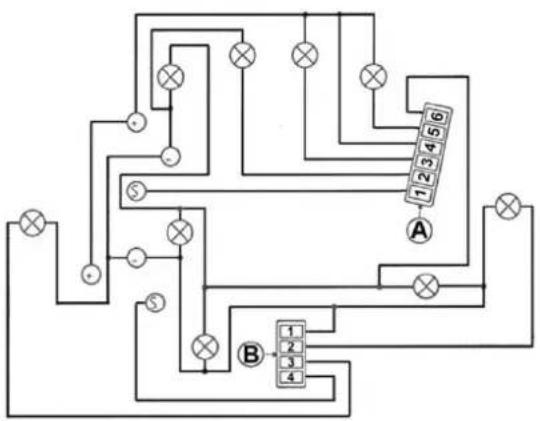
flowchart
graph TD
    A["Terminal A"] --> B["Component 1"]
    A --> C["Component 2"]
    A --> D["Component 3"]
    A --> E["Component 4"]
    B --> F["Terminal B"]
    C --> G["Terminal B"]
    D --> H["Terminal B"]
    E --> I["Terminal B"]
    style A fill:#f9f,stroke:#333
    style B fill:#ccf,stroke:#333
    style C fill:#ccf,stroke:#333
    style D fill:#ccf,stroke:#333
    style E fill:#ccf,stroke:#333
    style F fill:#dfd,stroke:#333
    style G fill:#dfd,stroke:#333
    style H fill:#dfd,stroke:#333
    style I fill:#dfd,stroke:#333
Dry-chargeBbattery
CheckingBtheBelectrolyteBlevel
The electrolyte level must be checked frequently and must reach the upper level. To restore such level, use only distilled water. If water topping is required too often, check the vehicle electric system: the battery works overcharged and is subject to quick wear.
CheckingBtheBbatteryBcharge
Dopo aver ripristinato il livello dell'elettrolito controllarne la densità con l'apposito densimetro
After restoring the electrolyte level, check its density using the density gauge.
With charged battery, density should be equal to 30 ÷ 32 Bé, corresponding to a specific weight of 1.26 ÷ 1.28 at a minimum temperature of 15^ C.
If density is below 20^ Bé, the battery is fully discharged and it is therefore necessary to recharge it.
If the vehicle is not used for a certain period (1 month and more), the battery needs periodical recharging.
The battery runs down totally within three months. When reinstalling the battery on the vehicle, be careful not to invert connections, considering that the earth wire (black) marked (-) must be connec-
ted to the -negative terminal, whereas the other two red wires marked (+) must be connected to the terminal marked with +positive sign.
CleaningBtheBbattery
The battery should always be kept clean, especially on its top side, and the terminals should be coated with vaseline.
CAUTION
NEVERBUSEBFUSESBHAVINGBABGREATERBCAPACITYBTHANBTHEBONEBRECOMMENDED. THEBUSEBOFBABFUSEBOFBUNSUITABLEBCAPACITYBMAYBRESULTBINBSERIOUSBDAMAGEBTO THEBWHOLEBVEHICLEBORBEVENBCAUSEBABFIRE.
CAUTION
NORMALBDRINKINGBWATERBCONTAINSBSALTSBTHATBAREBHARMFULBFORBBATTERIES.BUSEBONLYBDISTILLEDBWATER.
CAUTION
TOBENSUREBMAXIMUMPERFORMANCEBTHEBBATTERYBMUSTBBEBCHARGEDBBEFOREBUSINGBTHE VEHICLE.
INSUFFICIENTBBATTERYBCHARGEBORBLOWBELECTROLYTEBLEVELBWHENBFIRSTBUSEDBWILL RESULTBINBPREMATUREBFAILUREBOFBTHEBBATTERY.
BatteryBrecharge
Normal bench charging must be performed using the specific battery charger (single) or (multiple), setting the battery charge selector to the type of battery that requires recharging (i.e., at a current equal to 1/10 of the battery rated capacity). Connections to the power supply source must be implemented by connecting corresponding poles (+ to + and - to - ).
WARNING
BEFOREBRECHARGINGBTHEBBATTERY, BREMOVEBTHEBPLUGSBOFBEACHBELEMENT. KEEPBSPARKSBANDBFREEBFLAMESBAWAYBFROMBTHEBBATTERYBWHILEBRECHARGING. REMOVEBTHEBBATTERYBFROMBTHEBVHICLEBDISCONNECTINGBTHEBNEGATIVEBTERMINAL FIRST.
SpecificBtooling
020333YBSingleBbatteryBcharger
020334YBMultipleBbatteryBcharger
- Remove the short closed tube and its cap, then put sulphuric acid into the elements using a specific type for accumulators with a specific weight
of 1.26, corresponding to 30 Bé at a minimum temperature of 15^ C until the upper level is reached.
- Let stand for at least 2 hours, then restore the level with sulphuric acid.
- Within 24 hours, recharge using the specific battery charger (single) or (multiple) at an intensity of about 1/10 of the battery nominal capacity and until the acid density is about 1.27, corresponding to 31 Bé and such values become steady.
- After charging, level the acid (adding distilled water). Close and clean carefully.
- After performing the above operations, install the battery on the vehicle connecting.
SpecificBtooling
020333YBSingleBbatteryBcharger
020334YBMultipleBbatteryBcharger
1Bhold the tube upright
2Bvisually check the level
3 the float must be released
BatteryBinstallation
- Remove the battery cover by the 4 screws shown in the figure
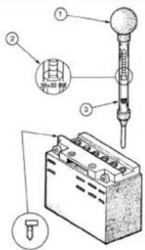

natural_image
Close-up of a metallic mechanical component with white directional arrows indicating movement or flow (no text or symbols)- Remove the battery fixing clamp
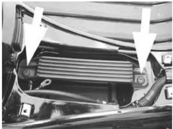
natural_image
Close-up of a car's front grille and engine compartment with white arrows pointing to structural components (no text or symbols visible)- Use the hole shown in the figure to insert the battery vent tube
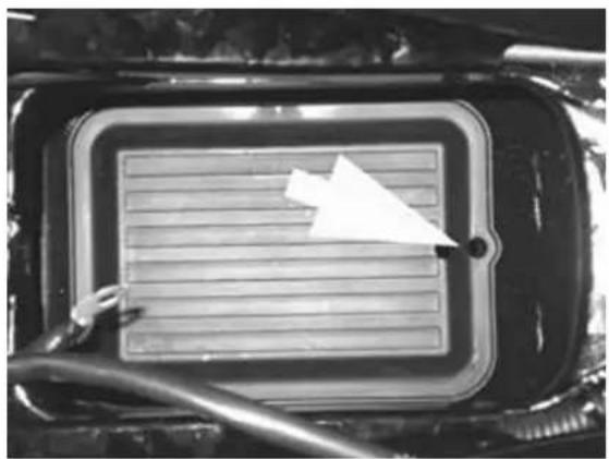
natural_image
Close-up of a car interior with a rectangular tray and a white paper airplane on the surface (no visible text or symbols)- Insert the battery as shown in the figure.
N.B.
INBORDERBTOBINSTALLBTHEBWIRESBONBTHEBBAT- TERYBTERMINALS BPROPERLY, BRESTBTHEBENDBOF THEBBATTERYBONBTHEBTERMINALBSIDEBONBTHE BATTERYBHOLDERBBASINBEDGE.B(SEEBSECTION)
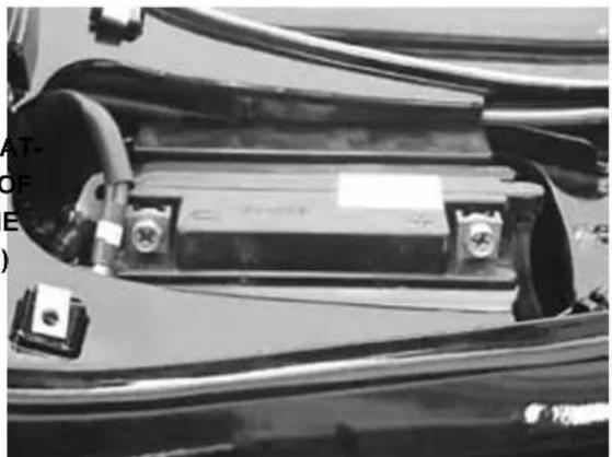
natural_image
Close-up of a car battery panel with visible circuitry and wiring (no text or symbols)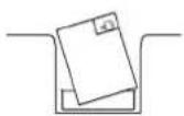
- Using a screwdriver lock the wires to the battery terminals placing the specific grover washer between the screw head and the wire terminal.
N.B.
DOBNOTBLOCKBTHEBSCREWSBFIXINGBTHEBTERMIN-
ALSBTOBTHEBBATTERYBUSINGBABWRENCH.
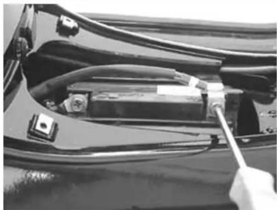
natural_image
Close-up of a car's front panel showing wiring and a tool inserted into the body (no visible text or symbols)- Finally insert the battery into the battery holder basin
- Replace the battery fixing clamp
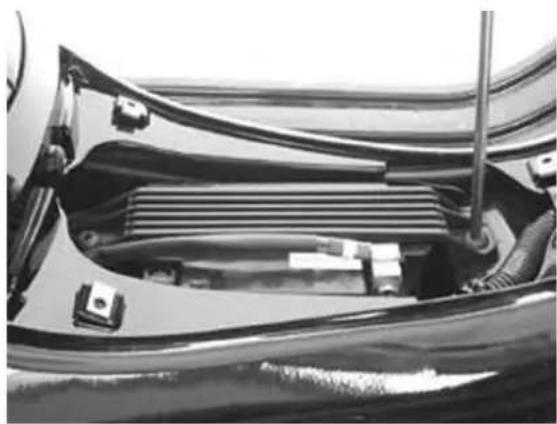
natural_image
Close-up of a car's front wheel assembly showing internal components and wiring (no text or symbols visible)- Replace the battery cover
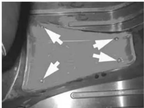
natural_image
Close-up of a metallic mechanical component with three white arrows pointing to specific areas (no text or symbols visible)INDEX OF TOPICS
ENGINE FROM VEHICLE
This section describes the operations to be carried out when removing the engine from the vehicle.
ExhaustBassy.BRemoval
- Loosen the two fasteners of the exhaust manifold from the head.
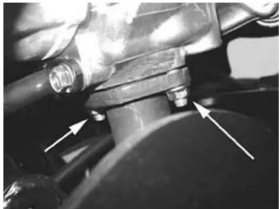
natural_image
Close-up of a mechanical component with arrows pointing to features, no visible text or symbols- Loosen the 3 screws fixing the silencer to the supporting arm.
- Remove the complete silencer.
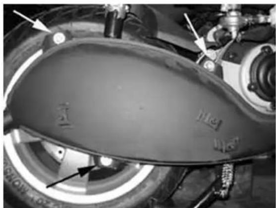
natural_image
Close-up of a motorcycle's front wheel and side gear, showing no visible text or symbolsRemovalBofBtheBengineBfromBtheBvehicle
- Perform the operations for removal in the reverse order according to the tightening torques indicated in Chapter Characteristics.
Check that with valve in abutment against the register there is a small clearance.
- Check the engine oil level and top up using the recommended brand, if required.
- Fill the cooling circuit.
- Check that accelerator and electric devices are in good working order.
CAUTION
BEBVERYBCAREFULBTOBENSUREBTHATBTHEBGASBCONTROLBTRANSMISSIONBISBINBPROPERBPOSITION.
- Disconnect the battery.
- Remove the helmet compartment.
- Remove the sides
- Remove the silencer
- Remove the cleaner box by releasing the 3 screws shown in the figure, removing the clip from the blow-by pipe and disconnecting the carburettor connection bellows by the clip as shown in the figure
CAUTION
THISBOPERATIONBSHOULDBBEBCARRIEDBOUTBON COLDBENGINE.
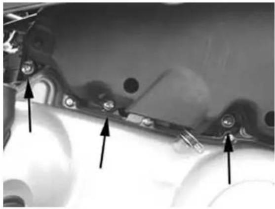
natural_image
Close-up of mechanical components with arrows pointing to features (no visible text or symbols)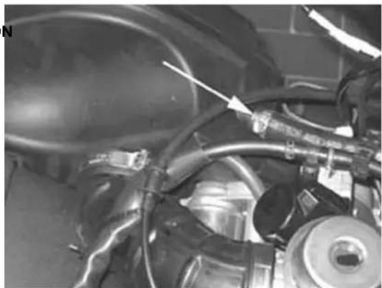
natural_image
Close-up of a mechanical assembly with hoses and components, no visible text or symbols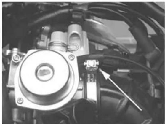
natural_image
Close-up of a mechanical assembly with visible components and wiring (no text or symbols)- Remove the air intake bellows in the transmission compartment by releasing the two screws shown in the figure and removing the plastic clip
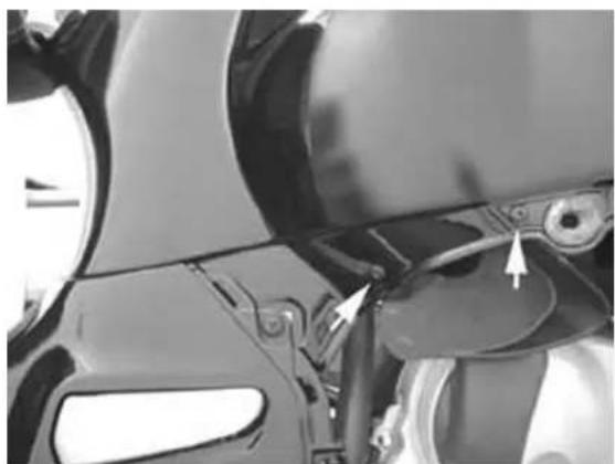
natural_image
Close-up of a mechanical component with arrows pointing to features, no visible text or symbols- Remove the cooling fluid inlet piping from the pump as shown in the figure
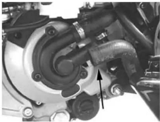
natural_image
Close-up mechanical assembly showing a valve and housing component with an arrow pointing to a specific part (no visible text or symbols)- Remove the fuel tap vacuum pipe from the «T» union shown in the figure
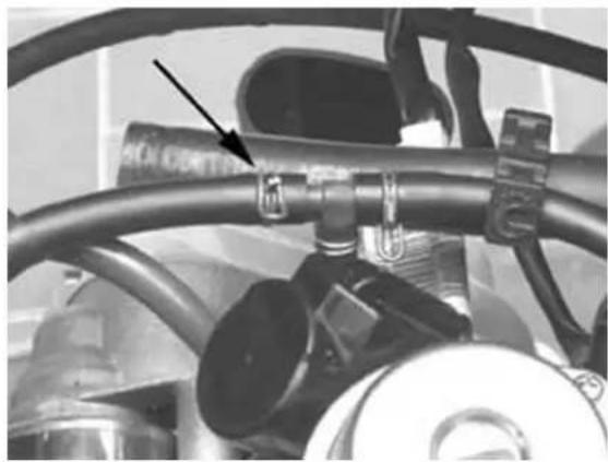
natural_image
Close-up of a mechanical pipe fitting with a black arrow pointing to a component (no visible text or symbols)- Remove the fuel feeding pipe from the carburet-tor
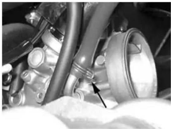
natural_image
Close-up of mechanical components with no visible text or symbols- Remove the cooling fluid outlet piping from the engine and the bleeding piping shown in the figure
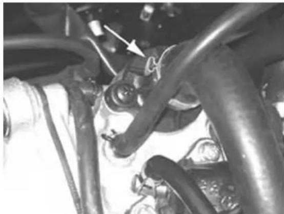
natural_image
Close-up of automotive engine components with visible hoses and springs (no text or symbols)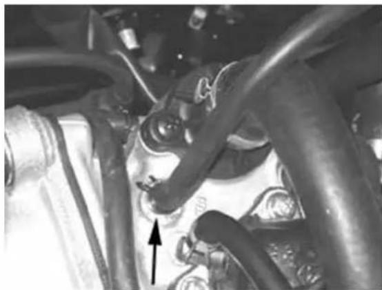
natural_image
Close-up of mechanical components with no visible text or symbols- Remove the spark plug cap
- Remove the cooling fluid temperature sensor connector shown in the figure
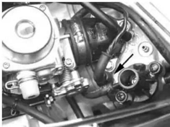
natural_image
Close-up mechanical assembly showing hoses, springs, and a valve (no visible text or symbols)- Remove the gas control cable from the carburet-tor by releasing the nut shown in the figure
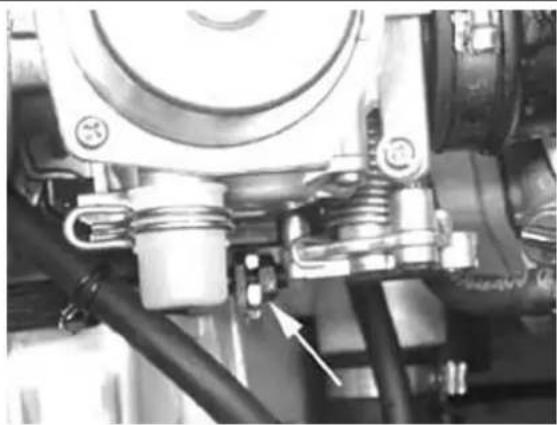
natural_image
Close-up of mechanical components with no visible text or symbols- Remove the automatic starter connector from the system located inside the protective sheath shown in the figure
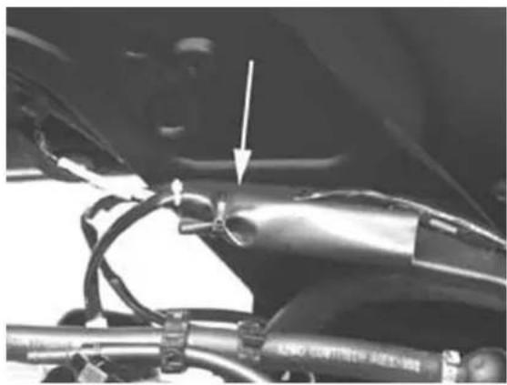
natural_image
Close-up of a car's engine components with hoses and a valve, no visible text or symbols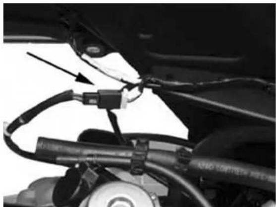
natural_image
Close-up of a vehicle's lower body showing hoses and wiring, with a black arrow pointing to a cable or connector (no visible text or symbols)- Remove the positive and negative wirings from the starter motor as shown in the figure
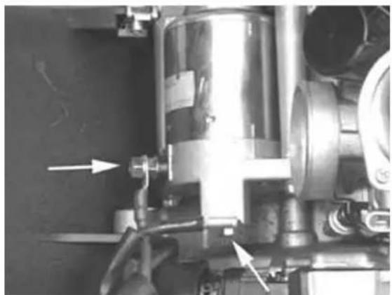
natural_image
Close-up of industrial machinery components with no visible text or symbols- Remove the flywheel wiring connector shown in the figure.
- Remove the cable from the flywheel cover retain clip
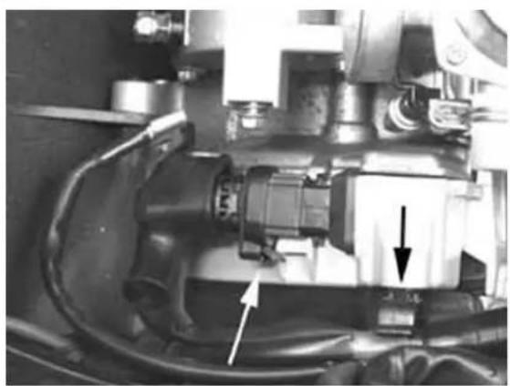
natural_image
Close-up mechanical assembly showing internal components and a directional arrow (no visible text or symbols)- Remove the rear shock absorbers
- Remove the hydraulic piping from the rear brake caliper by loosening the screw shown in the figure. Then, remove the pipe attachments to the engine crankcase shown in the figure
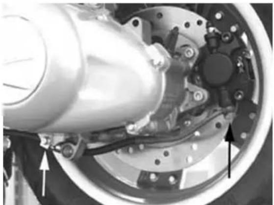
natural_image
Close-up of a mechanical assembly with visible components and arrows indicating parts (no text or symbols)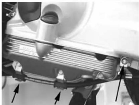
natural_image
Close-up of a mechanical assembly with arrows indicating parts, no visible text or symbols- Suitably support the vehicle by the jack. Remove the engine - oscillating arm by loosening the nut and the pin head shown in the figure - The engine can now be removed.
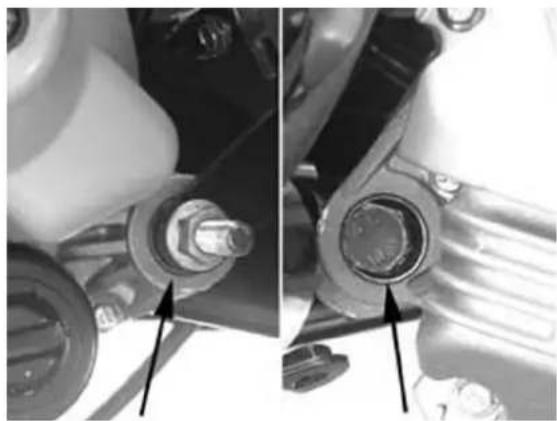
natural_image
Close-up of mechanical components with bolts and connectors, no visible text or symbolsINDEX OF TOPICS
ENGINE
This section describes the operations to be carried out on the engine and the tools required
Automatic transmission
Transmission cover
To remove the transmission cover it is necessary to remove the plastic cover first, using a screw-driver on the special guides. Using the clutch bell lock wrench shown in the figure, remove the driven pulley axle locking nut and washer.
Specific tooling
020423Y driven pulley stop key
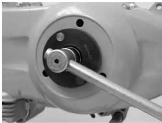
natural_image
Close-up of a mechanical assembly with a metallic rod inserted into a circular component (no visible text or symbols)- Remove the cap/bar of the engine oil filling hole.
- Remove the 10 screws.
- Remove the transmission cover.
If this operation is performed directly on the vehicle, it is necessary to remove the transmission compartment cooling air sleeve first.
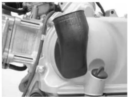
natural_image
Close-up of a white automotive engine compartment with visible battery and valve (no text or symbols)Air duct
Version 125
- Remove the 4 screws and the case.
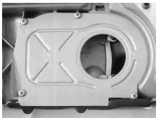
natural_image
Close-up of a mechanical component with a circular recess and mounting holes (no visible text or symbols)- Remove the 5 screws located on two different surfaces and the case.
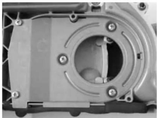
natural_image
Close-up of a mechanical component with circular housing and bolted joints (no visible text or symbols)- To remove the transmission cover intake, it is sufficient to remove the 2 screws indicated in the figure.
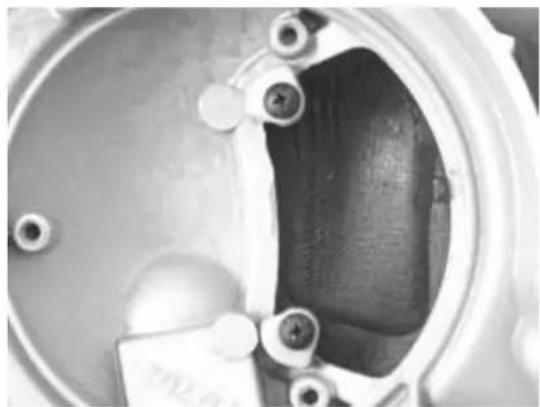
natural_image
Close-up of a mechanical component with metallic parts and a central cavity (no visible text or symbols)Removing the driven pulley shaft bearing
- Remove the snap ring from the cover internal side.
- Remove the bearing from the case using:
Specific tooling
020376Y Handle for punches
020375Y Adapter 28 x 30 mm
020412Y 15 mm guide
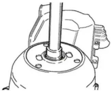
natural_image
Technical line drawing of a mechanical assembly with a central shaft and base mount (no text or symbols)Refitting the driven pulley shaft bearing
- Slightly warm the inside of the case to prevent
damaging the painted surface. - Install the bearing into its seat
- Replace the snap ring.
CAUTION
USEBANBAPPROPRIATEBRESTBSURFACEBTOBAVOID DAMAGINGBTHEBCOVERBPAINT.
N.B.
ALWAYSBREPLACEBTHEBBEARINGBWITHBABNEW ONEBUPONBREASSEMBLY.
SpecificBtooling
020376YBHandleBforBpunches
020357YB32BxB35BmmBadaptor
020412YB15BmmBguide
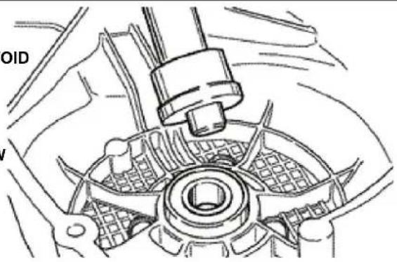
BaffleBroller
MetallicBroller
Removal
BeltBsupportBrollerB(onlyBforBversionB200Bcc)
- Check that the roller is free from wear and that it rotates freely.
- Remove the special fastening screw and the roller with bearing.
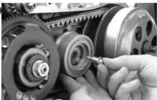
natural_image
Close-up of hands assembling mechanical gears and pulleys (no visible text or symbols)Refitting
- Warm the roller and install the bearing by the specific tool:
SpecificBequipmentBandBtools:
SpecificBtooling
020455YB10-mmBguide
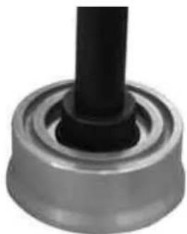
natural_image
Close-up of a mechanical component with a black cylindrical shaft and flange (no visible text or symbols)- Replace the roller with the special screw.
- Tighten at the prescribed torque.
- Replace the intake with the O-Ring, pan sealing gasket and fan case.
LockingBtorquesB(N*m)
Anti-flappingBrollerB12B÷B16
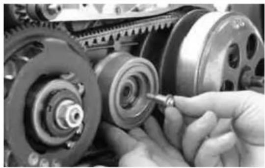
natural_image
Close-up of hands assembling mechanical gears and pulleys (no visible text or symbols)RemovingBtheBdrivenBpulley
Remove the spacer, the clutch bell and the entire driven pulley assembly.
N.B.
THEBASSEMBLYBMAYBALSOBBEBREMOVEDBWITH THEBDRIVINGBPULLEYBON.
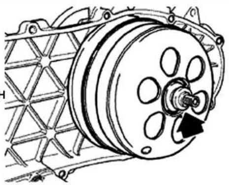
natural_image
Technical line drawing of a mechanical pulley system with no visible text or symbolsInspectingBtheBclutchBdrum
- Check that the clutch bell is not worn or damaged.
- Measure the clutch bell inside diameter.
Characteristic
MaxBvalueBclutchBbell
Max value: ∅ 134.5 mm
StandardBvalueBclutchBbell
Standard value: ∅ 134.2 mm
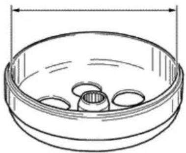
natural_image
Line drawing of a bowl with internal circular components and a dimension line (no text or symbols)CheckingBtheBbellBworkingBsurfaceBeccentricity
- Install the bell on a driven pulley shaft using 2
bearings (inside diameter 15 and 17 mm). - Lock using the original spacer and nut.
- Place the bell/shaft assembly on the support to check the driving shaft alignment.
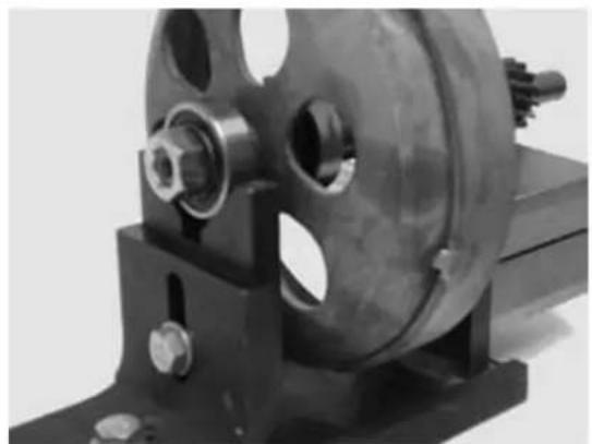
natural_image
Close-up of a mechanical gear assembly with mounting base and bolts (no visible text or symbols)- Using a feeler pin comparator and the magnetic base, measure the bell eccentricity.
- Repeat the measure in 3 positions (Central, internal, external).
- In case of anomalies, replace the bell.
Specific tooling
020074Y Crankshaft aligning tool
020335Y Magnetic stand and comparator
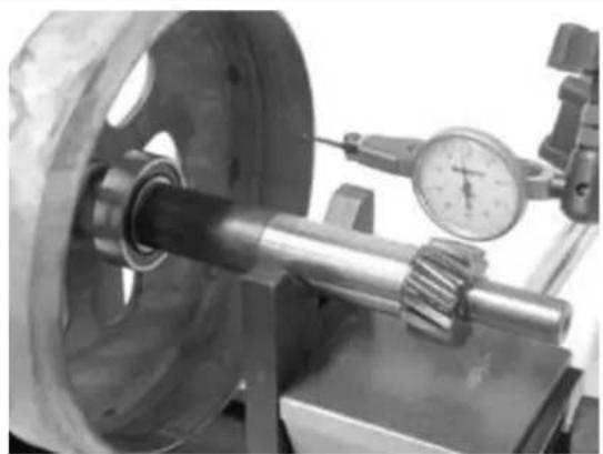
natural_image
Close-up of a mechanical tool with a dial indicator and rotating shaft (no visible text or symbols)Removing the clutch
Clutch removal (200cc)
- Prepare the specific driven pulley spring compressor tool with the medium length pins in position «C» tightened on the inside of the tool.
- Introduce the adapter ring n° 11 with the chamfering facing the inside of the tool.
- Install the driven pulley assembly onto the tool inserting the 3 pins into the ventilation holes obtained on the mass holding support.
- Make sure that the clutch is perfectly inserted into the adapter ring before proceeding to release and tighten the clutch nut.
- Using the specific wrench 46x55 component n°9, remove the clutch fixing nut.
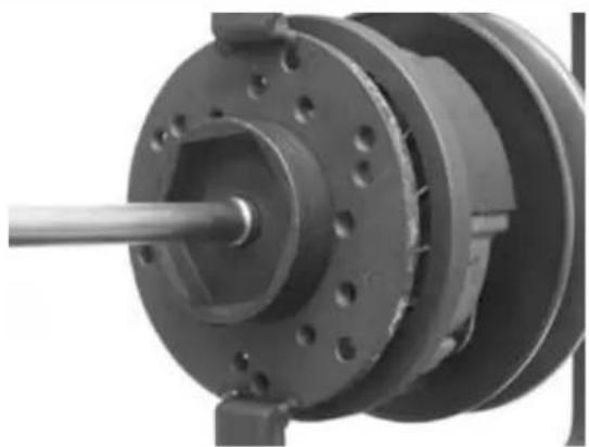
natural_image
Close-up of a mechanical component with a shaft and flanged housing (no visible text or symbols)- Separate the components of the driven pulley (clutch and spring with plastic rest).
CAUTION
THEBTOLLBMUSTBBEBTIGHTLYBFIXEDBINTHEBVICE ANDBTHEBCENTRALBSCREWBMUSTBBEBMOVEDBIN ABUTMENTBWITHBTHEBTOOL.BANBEXCESSIVE TORQUEBMAYBDEFORMBTHEBSPECIFICBTOOL.
SpecificBtooling
020444Y009BwrenchB46BxB55
020444Y011BAdapterBring
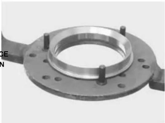
natural_image
Close-up of a mechanical flange component with bolt holes and central bore (no visible text or symbols)ClutchBremovalB(125ccBH2O)
- Prepare the specific driven pulley spring compressor tool with the medium length pins in position «F» tightened on the inside of the tool.
- Introduce the adapter ring n° 8 into the pins.
- Install the driven pulley assembly on the tool and the nail heads into the adapters.
- Make sure that the clutch is perfectly inserted into the adapter ring before proceeding to release and tighten the clutch nut.
- Using the specific wrench 46x55 component n°9, remove the clutch fixing nut.
- Separate the components of the driven pulley (clutch, fan and spring with plastic rest).
CAUTION
THEBTOLLBMUSTBBEBTIGHTLYBFIXEDBINBTHEBVICE ANDBTHEBCENTRALBSCREWBMUSTBBEBMOVEDBIN ABUTMENTBWITHBTHEBTOOL.BANBEXCESSIVE TORQUEBMAYBDEFORMBTHEBSPECIFICBTOOL.
SpecificBtooling
020444Y009BwrenchB46BxB55
020444Y008BadapterBring
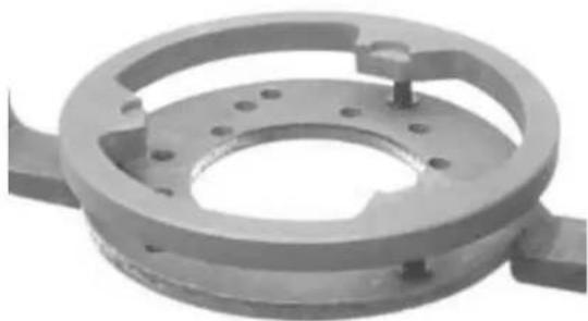
natural_image
Mechanical component with circular and ring features, no visible text or symbols
natural_image
Close-up of a mechanical assembly with a shaft and flanged housing (no visible text or symbols)InspectingBtheBclutch
- Check the thickness of the clutch mass friction material.
- The masses must exhibit no traces of lubricants; in that case, check the driven pulley unit seals.
N.B.
UPONBRUNNING-IN,BTHEBMASSESBMUSTBEX-HIBITBABCENTRALBCONTACTBSURFACEBAND MUSTBNOTBBEBDIFFERENTBFROMBONEBAN-OTHER.
DIFFERENTBCONDITIONSBMAYBCAUSEBTHE CLUTCHBTEARING.
CAUTION
DOBNOTBOPENBTHEBMASSESBUSINGBTOOLSBTO PREVENTBABVARIATIONBINBTHEBRETURNBSPRING LOAD.
Characteristic
CheckB.BMinimumBthickness
1 mm
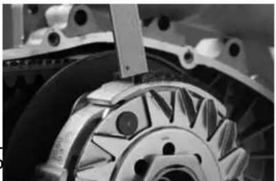
natural_image
Close-up of a mechanical gear assembly with visible teeth and mounting brackets (no text or symbols)PinBretainingBcollar
- Remove the collar by hand by turning and pulling at the same time.
N.B.
INBCASEBOFBDIFFICULTIES,BUSEB2BSCREW-DRIVERS.
N.B.
BEBCAREFULBNOTBTOBINSERTBTHEBSCREW-DRIVERSBTOOBMUCHBTOBPREVENTBDAMAGES THATBCOULDBAFFECTBTHEBO-RINGBSEAL.
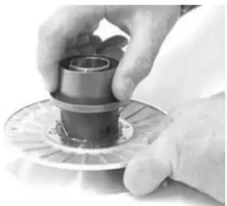
natural_image
Close-up of hands holding a mechanical component with a circular base (no visible text or symbols)- Remove the 4 pins of the servo-system and separate the half-pulleys.
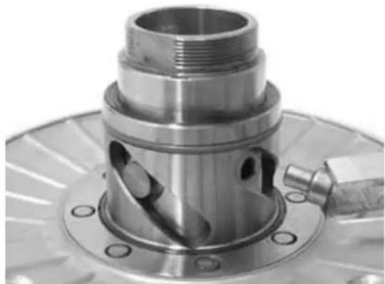
natural_image
Close-up of a metallic mechanical component with flanged base and threaded port (no visible text or symbols)RemovingBtheBdrivenBhalf-pulleyBbearing
- Check that there is no wear and/or noise; if not, replace.
- Remove the lock ring using two flat blade screw-drivers.
- Suitably support the pulley bushing from the threaded side on a wooden surface.
- Remove the ball bearing as shown in the figure, using a pin and a hammer.
- Suitably support the pulley.
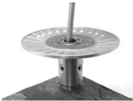
natural_image
Close-up of a metallic mechanical component with a circular flange and central shaft (no text or symbols visible)SpecificBtooling
001467Y035BBell
- Remove the roller bearing using the modular punch.
SpecificBtooling
020376YBHandleBforBpunches
020456YB∅B24BmmBadaptor
020363YB20mmBguide
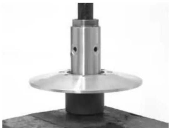
natural_image
Close-up of a mechanical component with a metallic cylindrical shaft and flange, mounted on a dark base (no visible text or symbols)InspectingBtheBdrivenBfixedBhalf-pulley
- Measure the pulley bushing outside diameter.
- Check that the contact surface with the belt is free from abnormal wear.
- Check the riveting.
- Check the belt contact surface planarity.
Characteristic
Minimum diameter half-pulley
Minimum admissible diameter: ∅ 40,96 mm
Standard diameter half-pulley
Standard diameter: ∅ 40,985 mm
Wear limit
0,3 mm
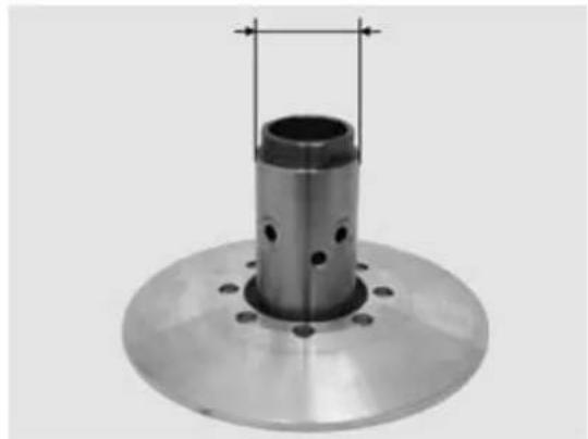
natural_image
Metal mechanical component with cylindrical shaft and flange, shown with measurement lines (no text or symbols)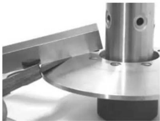
natural_image
Close-up of a metallic mechanical component with a flanged base and cylindrical shaft (no visible text or symbols)Version 125
- Measure the pulley bushing outside diameter.
- Check that the contact surface with the belt is free from abnormal wear.
Characteristic
Standard diameter half-pulley
Standard diameter: ∅ 40,985 mm
Minimum diameter half-pulley
Minimum admissible diameter: ∅ 40,96 mm
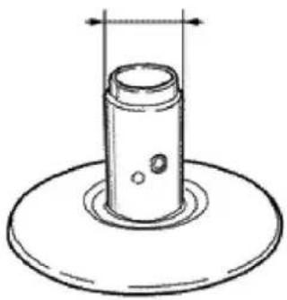
natural_image
Simple line drawing of a cylindrical object with a base, no text or symbols presentInspecting the driven sliding half-pulley
Version 125
- Remove the 2 inside sealing rings and the 2 O-rings
- Measure the mobile half-pulley bushing inside diameter
Characteristic
MaximumBdiameterBmobileBdrivenBhalf-pulley
Maximum admissible diameter ∅ 41,08 mm
StandardBdiameterBmobileBdrivenBhalf-pulley
Standard diameter: ∅ 41.000 ÷ 41.035 mm
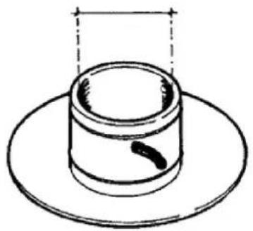
natural_image
Simple line drawing of a cylindrical object with a small dark mark on its side, placed above a circular base (no text or symbols)- Remove the 2 inside sealing rings and the 2 O-rings;
- Measure the mobile half-pulley bushing inside diameter.
- Check that the surface of contact with the belt does not show abnormal wear.
- Check the functionality of the riveting.
- Check the planarity of the belt surface of contact.
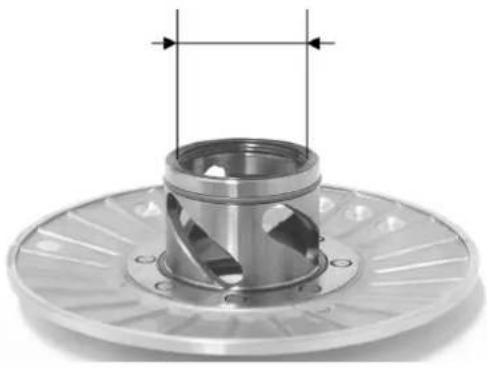
natural_image
Mechanical component with a central cylindrical shaft and flanged base, shown with dimension lines (no text or symbols)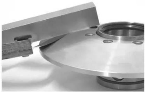
natural_image
Close-up of a metallic mechanical component with a wooden handle and circular base (no visible text or symbols)MOBILEBLINEBHALFBPULLEYBDIMENSIONS
SpecificationBDesc./Quantity
| Wear limit,0,3 mm | |
| Standard diameter | 41,000 ÷ 41,035 |
| Maximum admissible diameter | 41,08 mm |
- Remove the belt and extract the mobile half-pulley with the relevant bushing, being careful to the exit of the rollers freely mounted onto it.
- Remove the roller contrast plate with the relevant guide sliding blocks.
RefittingBtheBdrivenBhalf-pulleyBbearing
- Suitably support the pulley bushing from the
threaded side on a wooden surface.
- Install a new roller casing as shown in the figure.
- To install the new ball bearing, proceed as
shown in the figure using the modular punch. - Install the lock ring
N.B.
INSTALLBTHEBBEARINGBWITHBVISIBLEBSCREENING.
SpecificBtooling
020376YBHandleBforBpunches
020375YBAAdapterB28BxB30Bmm
020424YBDrivenBpulleyBrollerBcasingBdrift
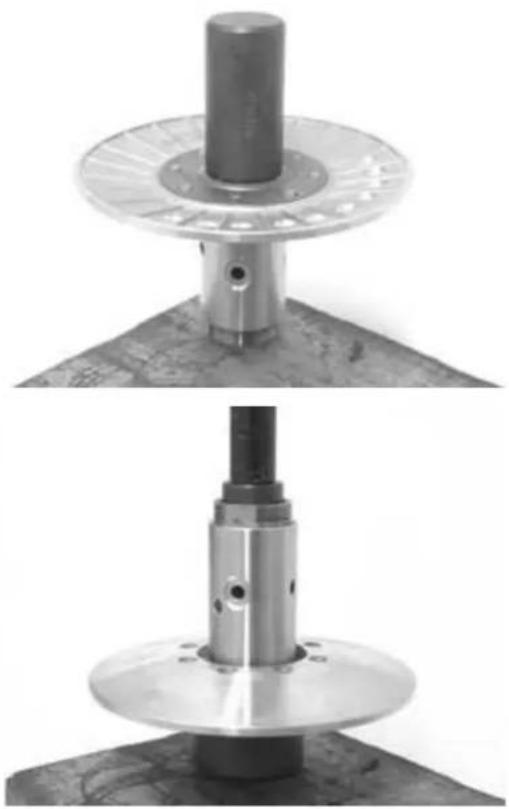
natural_image
Two views of a mechanical assembly with a cylindrical component mounted on a circular base, shown from different angles (no text or symbols visible)RefittingBtheBdrivenBpulley
Version 125
- Insert the new oil guards and O-Rings on the mobile half-pulley.
- Slightly grease the O-Rings (A) shown in the figure.
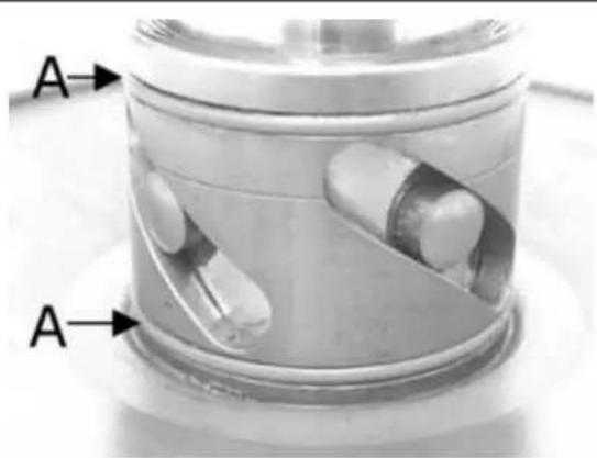
- Insert the new oil guards and O-Rings on the mobile half-pulley.
- Slightly grease the O-Rings (A) shown in the figure.
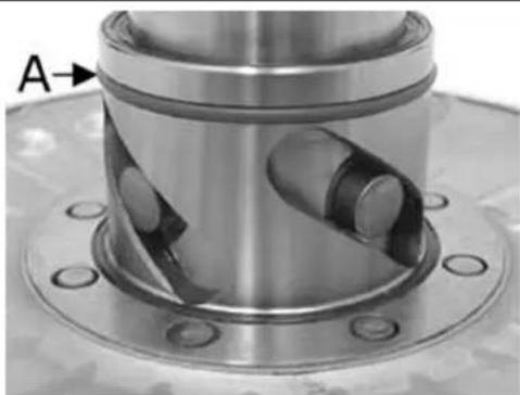
natural_image
Close-up of a mechanical component with flanged base and central bore, labeled 'A' with arrow pointing to a feature (no text or symbols beyond label)- Install the half pulley on the bushing using the specific tool
- Check that the pins are free from wear and reassemble into the relative slits.
- Replace the collar to close the servo-system.
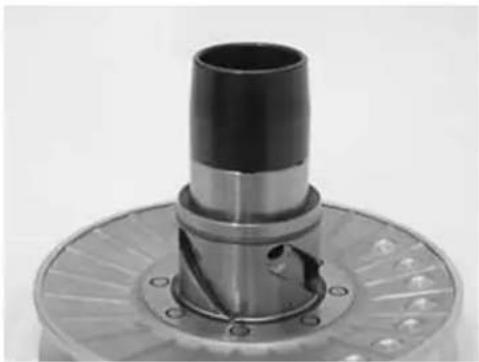
natural_image
Close-up of a mechanical component with a cylindrical shaft and flanged base (no visible text or symbols)Using a bent beak greaser, lubricate the driven pulley unit with about 6 gr. of grease, this operation should be carried out through one of the two holes into the bushing to obtain the exit of the grease from the opposite hole. This operation is required to prevent the presence of grease beyond the O-rings.
N.B.
THEBSERVO-SYSTEMBMAYBBEBLUBRICATEDBBOTH WITHBBEARINGSBMOUNTEDBORBUPONBTHEIRBRE-PLACEMENT;BTHEBINTERVENTIONBCARRIEDBOUT DURINGBTHEBBEARINGBOVERHAULINGBMAYBBE EASIER
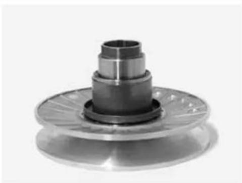
natural_image
Close-up of a mechanical component with concentric cylindrical sections and a flanged base (no visible text or symbols)SpecificBtooling
020263YBProtectiveBsheath
RecommendedBproducts
TUTELABMRMB2BGreaseBforBtheBphonicBwheel turningBring
Molybdenum disulphide grease and lithium soap
Inspecting the clutch spring
- Measure the free length of the mobile driven half-pulley spring.
Characteristic
Standard length (125)
106 mm
Limit after use (125)
101 mm
Standard length (200 - 250)
123 mm
Limit after use (200 - 250)
118 mm
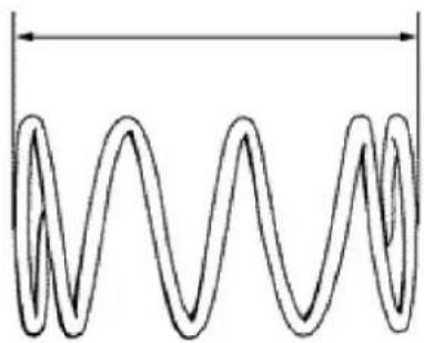
natural_image
Pure diagram of a helical spring without any text, numbers, or symbolsRefitting the clutch
- Support the driven pulley spring compressor specific tool with the control screw in vertical axis.
- Arrange the tool with the medium length pins screwed in position «C» on the inside.
- Introduce the adapter ring n° 11 with the chamfering facing upwards.
- Insert the clutch on the adapter ring.
- Lubricate the end of the spring that abuts against the servo-system closing collar.
- Insert the spring with relevant plastic support in contact with the clutch.
- Insert the driving belt into the pulley unit according to their direction of rotation.
- Insert the pulley unit with the belt into the tool.
- Slightly pre-load the spring.
- Make sure that the clutch is perfectly inserted into the adapter ring before proceeding to tighten the clutch nut.
- Place the tool into the vice with the control
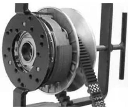
natural_image
Close-up of a mechanical gear assembly with mounting flange and meshed shaft (no visible text or symbols)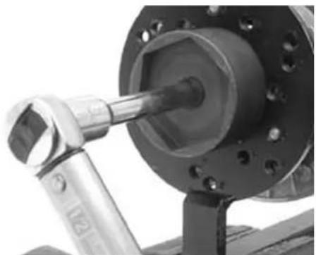
natural_image
Close-up of a mechanical tool interacting with a flanged mechanical component (no visible text or symbols)screw in horizontal axis.
- Fully pre-load the spring.
- Apply the clutch fixing nut and tighten it at the prescribed torque using the specific wrench 46x55.
- Loosen the tool clamp and insert the belt according to its direction of rotation.
- Lock the driven pulley again using the specific tool.
- Pre-load the clutch contrast spring by turning and pulling at the same time and place the belt in the minimum rolling diameter position.
- Remove the driven pulley /belt assembly from the tool.
N.B.
DURINGBTHEBSPRINGBPRE-LOADINGBSTEP,BBE CAREFULBNOTBTOBDAMAGETHEBSPRINGBPLASTIC ABUTMENTBANDBTHEBBUSHINGBTHREADING.
N.B.
FORBDESIGNBREASONS, BTHEBNUTBISBSLIGHTLY ASYMMETRIC; BTHEBSURFACEBSHOULDBBEBMOUNTEDBINBCONTACTBWITHBTHEBCLUTCH.
SpecificBtooling
020444YBDrivenBhalfBpulleyBspringBcompressor tool
020444Y011BAdapterBring
020444Y009BwrenchB46BxB55
LockingBtorquesB(N*m)
NutBlockingBclutchBassemblyBonBpulleyB55B÷B60 Nm
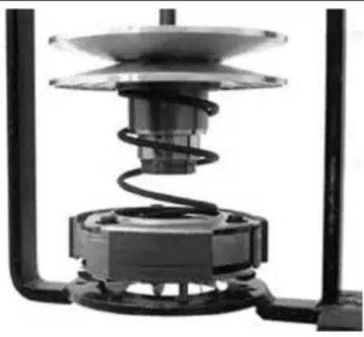
natural_image
Mechanical assembly diagram showing a spring-loaded component with a dome-shaped top and base (no text or symbols visible)Version 125
- Support the driven pulley spring compressor
specific tool with the control screw in vertical axis. - Arrange the tool with the medium length pins
screwed in position «F» on the inside.
- Introduce the adapter ring n° 8 into the pins.
- Pre-assemble the clutch cooling fan in the position in which the keying facets are aligned and the 3 pin heads (A) are fully visible.
- Insert the clutch on the adapter ring.
- Lubricate the end of the spring that abuts against the servo-system closing collar.
- Insert the spring with relevant plastic support in contact with the clutch.
- Insert the driving belt into the pulley unit according to their direction of rotation.
- Insert the pulley unit with the belt into the tool.
- Slightly pre-load the spring.
- Make sure that the clutch is perfectly inserted into the adapter ring before proceeding to tighten the clutch nut.
- Place the tool into the vice with the control screw in horizontal axis.
- Fully pre-load the spring.
- Apply the clutch fixing nut and tighten it at the prescribed torque using the specific wrench 46x55.
- Loosen the tool clamp and insert the belt according to its direction of rotation.
- Lock the driven pulley again using the specific tool.
- Pre-load the clutch contrast spring by turning and pulling at the same time, up to reaching the maximum pulley opening and place the belt on the minimum rolling diameter.
- Remove the driven pulley /belt assembly from the tool.
N.B.
FORBDESIGNBREASONS, BTHEBNUTBISBSLIGHTLY ASYMMETRIC; BTHEBSURFACEBSHOULDBBEBMOUN-
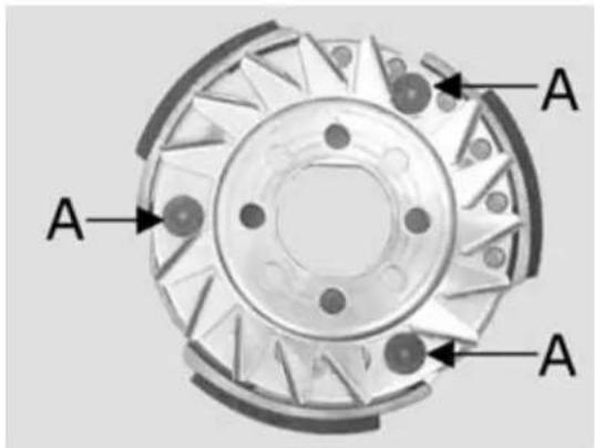
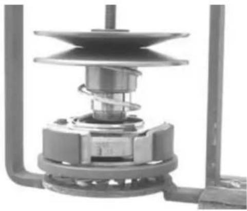
natural_image
Mechanical assembly diagram showing a spring-loaded component with no visible text or symbols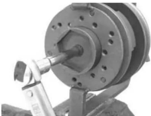
natural_image
Close-up of a mechanical assembly with a cylindrical component and a tool, no visible text or symbols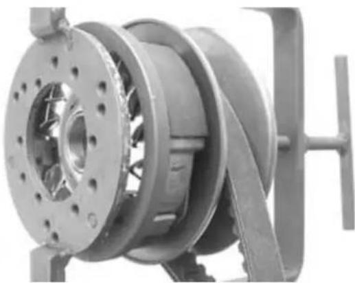
natural_image
Close-up of a mechanical pump assembly with visible internal components and mounting bracket (no text or symbols)TEDBINBCONTACTBWITHBTHEBCLUTCH.
N.B.
DURINGBTHEBSPRINGBPRE-LOADINGBSTEP,BBE CAREFULBNOTBTOBDAMAGETHEBSPRINGBPLASTIC ABUTMENTBANDBTHEBBUSHINGBTHREADING.
N.B.
ANBEXCESSIVEBAMOUNTBCOULDBIMPAIRBTHE CLUTCHBFUNCTIONS.
SpecificBtooling
020444Y011BAdapterBring
020444Y009BwrenchB46BxB55
LockingBtorquesB(N*m)
ClutchBfixingBnutB55B÷B60
RefittingBtheBdrivenBpulley
- Reinstall the clutch bell and the spacer.
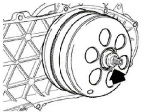
natural_image
Technical line drawing of a mechanical pulley system with a rotating wheel (no text or symbols)Drive-belt
During the wear check to be performed according to the scheduled maintenance in the 6,000 Km inspection, in the 18,000 Km inspection, etc., it is advisable to check that the tooth groove bottom is free from deformations and cracks (see figure). In case of cracks, the belt must be replaced. «A»: The tooth groove bottom must be free from deformations and cracks; if not, replace the belt.
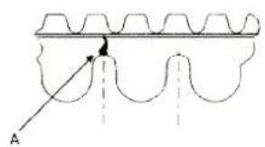
- Check that the driving belt is not damaged.
- Check the belt width.
Characteristic
Driving belt standard width
22.5 ± 0.2 mm
Driving belt minimum width
21.5 mm
Driving belt standard width
20.5 ± 0.2 mm
Driving belt minimum width
19.5 mm
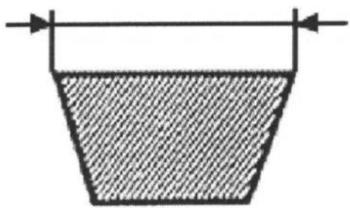
natural_image
Simple line drawing of a container with a handle and arrow, no text or symbols present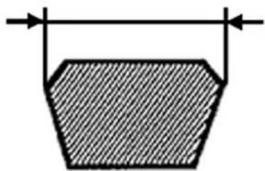
natural_image
Simple geometric diagram of a trapezoidal shape with horizontal arrows indicating width (no text or symbols)Removing the driving pulley
Driving pulley removal
- Using the specific tool inserted into the slits, remove the nut with the built-in spring washer.
Specific equipment and tools:
Specific tooling
020442Y pulley stop wrench
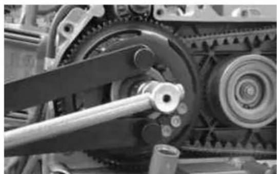
natural_image
Close-up of mechanical gears and chains with visible shafts and housing (no text or symbols)- Remove the start-up rim assembly with torque limiter.
- Remove the fixed driving half-pulley with the O-ring and the steel washer in contact with the bushing.
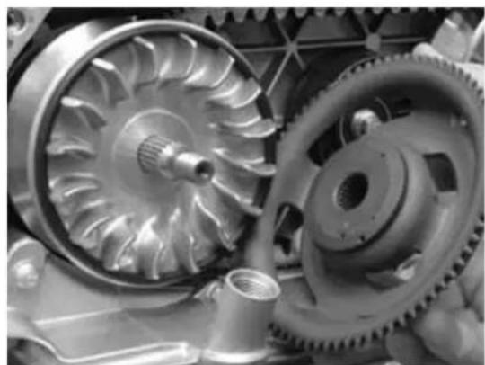
natural_image
Close-up of mechanical gears and shafts in a vehicle assembly (no visible text or symbols)DrivingBpulleyBremovalB(125)
- Using the specific tool, remove the nut with the built-in spring washer, the drive for the versions with kick-starter, and the steel washer.
- Remove the fixed driving half-pulley.
- Remove the steel separation washer from the bushing.
SpecificBequipmentBandBtools:
SpecificBtooling
020368YBdrivingBpulleyBstopBwrench
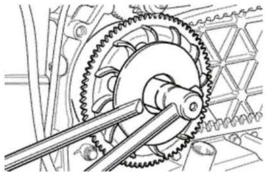
natural_image
Mechanical gear assembly diagram showing meshing gears and shafts (no text or labels)InspectingBtheBrollersBcase
- Check that the inside brass shown in the figure is not worn and measure the inside diameter
- Measure the pulley sliding bushing outside diameter shown in the figure.
- Check that the rollers are not damaged or worn.
- Check that the roller contrast plate slide blocks are not damaged.
- Check the wear of the roller housings and of the belt contact surfaces on both half-pulleys.
- Check that the fixed driving pulley exhibits no abnormal wear on the grooved profile and on the belt contact surface.
- Check that the O-Ring is not deformed.
CAUTION
DOBNOTBLUBRICATEBORBCLEANBTHEBBUSHES.
Characteristic
RollerB(200cc):BMinimumBdiameter
∅ 20 mm
RollerB(125cc):BMinimumBdiameter
∅ 18,5 mm
SlidingBshimBcylinder:BMin.BAllowedBdiameter
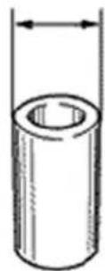
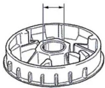
natural_image
Technical line drawing of a mechanical gear or impeller component (no text or symbols)∅ 25,95 mm
Mobile driving half pulley brass: Max allowed diameter
26,12 mm
Roller (200cc): Standard diameter
∅ 20,5 ÷ 20,7 mm
Roller (125cc): Standard diameter
∅ 18,9 ÷ 19,1 mm
Sliding shim cylinder: Standard Diameter
∅ 25,959 ÷ 25,98 mm
Mobile driving half pulley brass: Standard Diameter
26,000 ÷ 26,021 mm

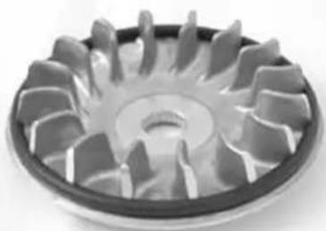
natural_image
Close-up of a metallic gear with multiple teeth and central hub (no text or symbols visible)Refitting the driving pulley
- Properly reinstall the bendix into its seat, if removed.
- Install the steel shim in contact with the bushing and the fixed driving half-pulley with the O.R. on the external end of the ventilation blades.
- Install the start-up rim assembly with torque limiter.
- Insert the torque limiter on the driving shaft so as to ensure the alignment of the references obtained on the start-up rim and on the fixed driving
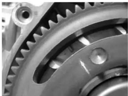
natural_image
Close-up of interlocking gears and shafts in a mechanical assembly (no text or symbols visible)half-pulley. If this is not possible, choose the position where the references are closest to one another.
- Failure to comply with this rule can impair the cooling fan efficiency.
- The lock wrench works on the start-up rim.
- If the torque limiter is worn, it is possible to detect the fault when locking of the nut on the driving shaft.
- The torque limiter cannot be overhauled.
- In case of anomalies, replace the start-up rim with the limiter.
Specific tooling
020442Y pulley stop wrench
Recommended products
Loctite "Super Rapido" Loctite "Super Rapido" 243
Apply Loctite "Super Rapido" 243 on the threads and tighten the nut with the washer at the prescribed torque.
Locking torques (N\*m)
Driving pulley screw 75 ÷ 83
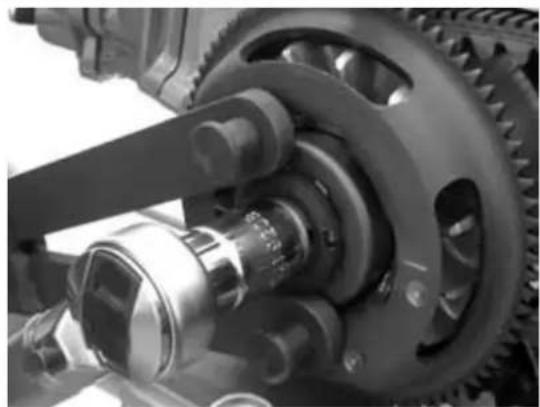
natural_image
Close-up of a mechanical gear assembly with visible shafts and housing (no text or symbols)- Properly reinstall the bendix into its seat, if removed.
- Reinstall the group components (inside shim, fixed half-pulley, outside shim, drive and nut), apply thread-holding Loctite type "Super Rapido" 243 on the threading and tighten the nut at the prescribed torque.
- Prevent the half-pulley rotation using the specific lock wrench.
- Turn the engine by hand to obtain a minimum
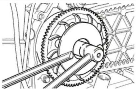
natural_image
Mechanical gear assembly diagram showing meshing gears and shafts (no text or labels)tension of the belt.
CAUTION
ITBISBVERYBIMPORTANTBTOBINSTALLBTHEBFIXED DRIVINGBHALF-PULLEYBWITHBTHEBBELTBTOTALLY FREEBTOBPREVENTBABFALSEBLOCKINGBOFBTHE DRIVINGBHALF-PULLEY.
SpecificBtooling
020368YBdrivingBpulleyBstopBwrench
LockingBtorquesB(N*m)
DrivingBpulleyBscrewB75B÷B83
- Pre-assemble the mobile half-pulley with the roller contrast plate, placing the rollers in the specific slits with the larger matching surface in contact with the pulley according to the direction of rotation.
- Check that the roller contact plate exhibits no anomalies or damages on the grooved profile.
- Install the group with the bushing on the driving shaft.
- Install the driven pulley/clutch/belt assembly on the engine.
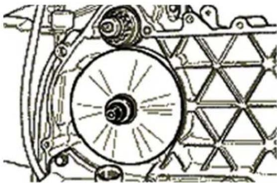
natural_image
Technical line drawing of a mechanical assembly with gears and shafts (no text or symbols)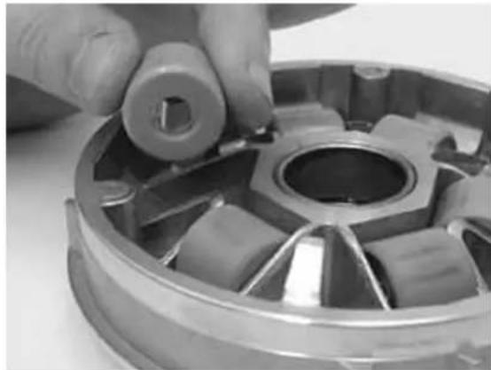
natural_image
Close-up of a hand holding a mechanical component, showing internal parts and mounting holes (no text or symbols visible)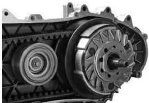
natural_image
Close-up of a tracked vehicle with visible gears and shafts (no text or symbols)Refitting the transmission cover
- Check the presence of the 2 centring dowels and the correct installation of the sealing gasket for the oil sump on the transmission cover.
- Replace the cover tightening the 10 screws at the prescribed torque.
- Replace the oil loading cap/bar.
- Replace the steel washer and the driven pulley nut.
- Tighten the nut at the prescribed torque using the lock wrench and the dynamometric wrench tools.
- Replace the plastic cover.
Specific tooling
020423Y driven pulley stop key
Locking torques (N*m)
Cover screws 11 ÷ 13 Driven pulley axis (°) 54 ÷ 60
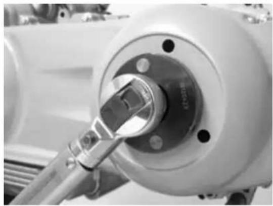
natural_image
Close-up of a mechanical component with a metallic tool inserted, showing no visible text or symbols.End gear
Removing the hub cover
- Drain the rear hub by the oil drainage cap.
- Remove the 7 flanged screws shown in the figure.
- Remove the hub cover and the relevant gasket.
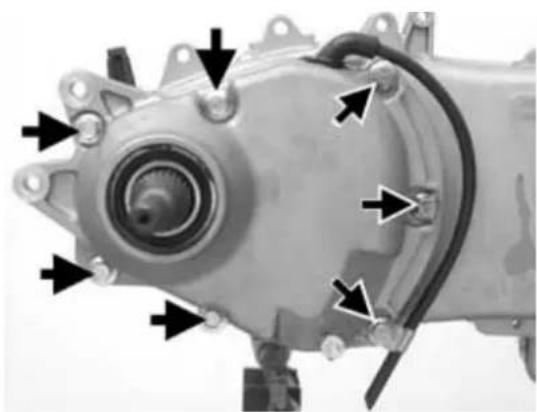
natural_image
Close-up of a mechanical electric motor with mounting flanges and wiring (no visible text or symbols)Removing the wheel axle
- Remove the wheel axle with gear.
- Remove the intermediate gear.
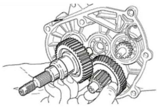
natural_image
Mechanical gear assembly diagram showing interlocking gears and shafts (no text or labels)Removing the hub bearings
- Check all bearings (wear, clearance and noise). In case of anomalies, proceed as follows.
- To remove the 3 15-mm bearings (2 on the crankcase and 1 on the hub cover) use the specific removing tool.
Specific tooling
001467Y013 15-mm pliers
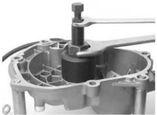
natural_image
Close-up of a mechanical component with internal gears and shaft (no visible text or symbols)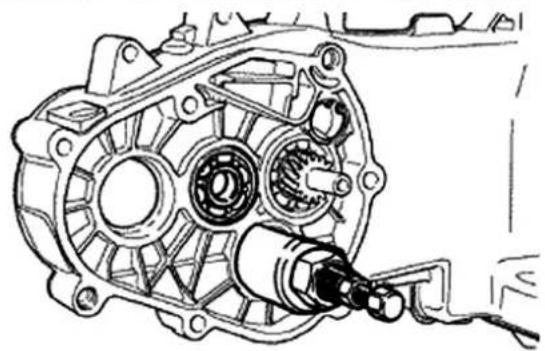
natural_image
Technical line drawing of a mechanical assembly with gears and housing (no text or symbols)Removing the wheel axle bearings
Remove the oil guard using the specific tools, as shown in the figure.
Specific tooling
020376Y Handle for punches
020477Y Adapter 37 mm
020483Y 30 mm guide
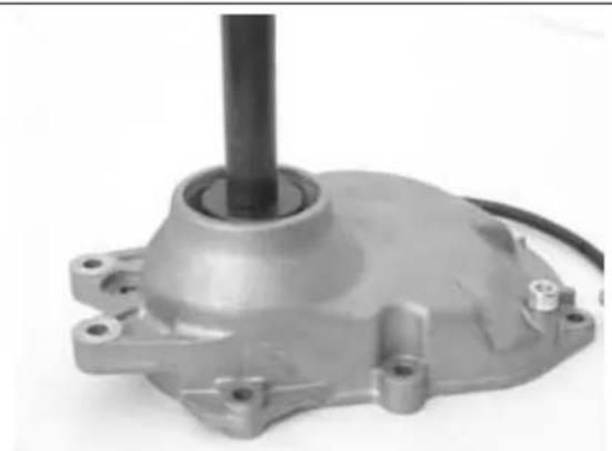
natural_image
Close-up of a metallic mechanical component with a cylindrical shaft and mounting flange (no visible text or symbols)Support the hub cover and eject the bearing.
Specific tooling
020359Y 42 x 47 mm hub bearing fitting adaptor
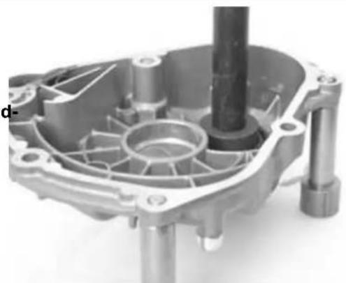
natural_image
Mechanical component with internal gears and shafts, no visible text or symbolsRemoving the driven pulley shaft bearing
- In order to remove the driven pulley shaft, together with its bearing and oil seal, first remove the transmission cover and the clutch assembly as previously described.
- Extract the driven pulley shaft from its bearing.
- Remove the oil seal, working from the inside of the bearing.
- Remove the circlip, as shown in the diagram.
Remove the driven pulley shaft bearing using the appropriate special tool.
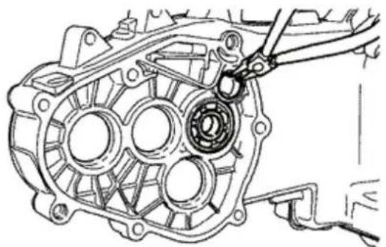
natural_image
Technical line drawing of a mechanical assembly with gears and clamps (no text or symbols)Specific tooling
020376Y Handle for punches
020375Y Adapter 28 x 30 mm
020363YB20mmBguide
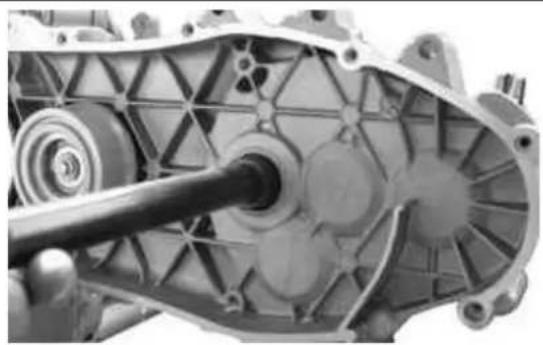
natural_image
Close-up of a mechanical gear assembly with visible gears and shaft (no text or symbols)InspectingBtheBhubBshaft
- Check that the three shafts exhibit no wear or deformation on the toothed surfaces, at the bearing connections and at the oil guards.
- In case of anomalies, replace the damaged components.
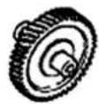
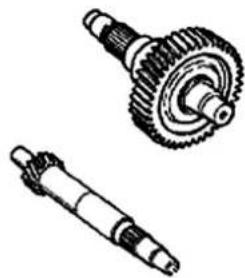
natural_image
Technical drawings of two mechanical gears and shafts (no text or symbols)InspectingBtheBhubBcover
- Check that the matching surfaces exhibit no deformations.
- Check the bearing connections.
- In case of anomalies, replace the damaged components.
RefittingBtheBwheelBaxleBbearing
Place the hub cover on a wooden surface.
- Warm the cover case by the specific thermal gun.
- Install the wheel axle bearing using the modular punch as shown in the figure.
SpecificBtooling
020150YBSupportBforBairBheaterB"METABOBHG 1500/2"
020151YBAirBheaterB"METABOBHGB1500/2"
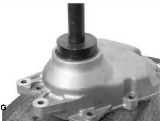
natural_image
Close-up of a mechanical component with a cylindrical shaft and flanged base (no visible text or symbols)020376YBHandleBforBpunches
020360YB52BxB55BmmBadaptor
020483YB30BmmBguide
Install the snap ring.
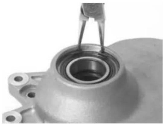
natural_image
Close-up of a mechanical component with a metallic bearing and metal bracket (no visible text or symbols)- Install the oil guard with the sealing lip facing the inside of the hub and place it flush with the internal surface using the specific tool on the 52 mm side.
The 52-mm side of the adapter must face the bearing.
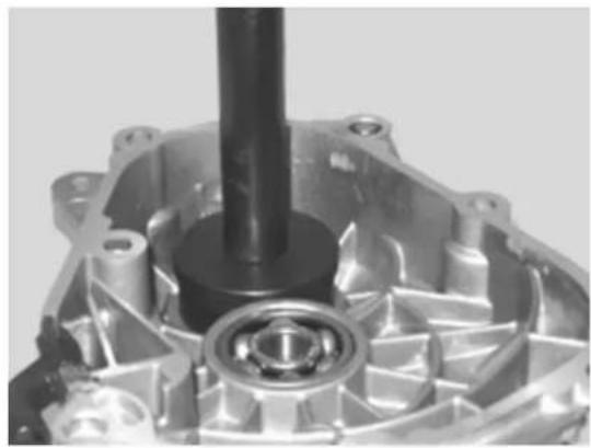
natural_image
Close-up of a mechanical gear assembly with a central shaft and housing (no visible text or symbols)RefittingBtheBhubBcoverBbearings
To install the hub box bearings you must warm the engine crankcase and the cover by the specific thermal gun.
- The three 15-mm bearings must be installed using the specific tools:
The 42-mm side of the adapter must face the bearing.
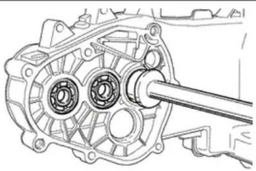
natural_image
Technical line drawing of a mechanical assembly with gears and shaft (no text or symbols)SpecificBtooling
020150YBSupportBforBairBheaterB"METABOBHG 1500/2"
020151YBAirBheaterB"METABOBHGB1500/2"
020376YBHandleBforBpunches
020359YB42BxB47BmmBhubBbearingBfittingBadaptor
020412YB15BmmBguide
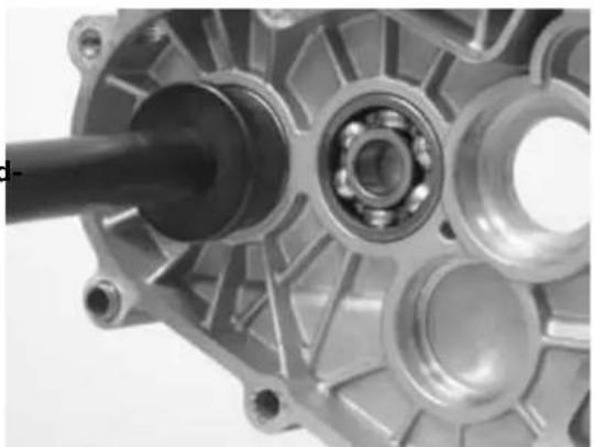
natural_image
Close-up of a mechanical assembly showing internal components and a shaft (no visible text or symbols)N.B.
TOBINSTALLBTHEBBEARINGBONBTHEBCOVER,BSUITABLYBSUPPORTBTHEBCOVERBBYBTHEBCOLUMNBKIT
Replace the driven pulley axle bearing using the modular punch as shown in the figure.
N.B.
IFBTHEBBEARINGBISBOFBTHEBASYMMETRICBBALL CONTAINMENTBTYPE,BPLACEBITBWITHBVISIBLE BALLSBONBTHEBHUBBINTERNALBSIDE.
SpecificBtooling
020376YBHandleBforBpunches
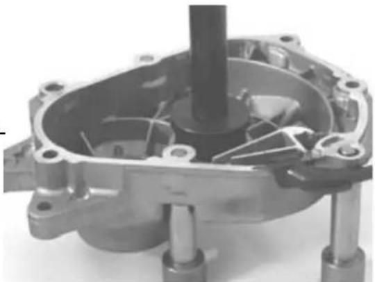
natural_image
Close-up of a mechanical assembly with internal components and mounting feet (no visible text or symbols)020359YB42BxB47BmmBhubBbearingBfittingBadaptor
020363YB20mmBguide
N.B.
TOBINSTALLBTHEBBEARINGSBONBTHEBENGINEBCRANKCASEBTHEBLATTERBSHOULDBBEBSUPPORTEDBON ABSURFACEBTOBALLOWBPLACINGBTHEBBEARINGSBVERTICALLY.
Replace the snap ring placing the opening at the side opposed the bearing and the new oil guard flush with the crankcase on the pulley side.
RefittingBtheBhubBbearings
- Install the 3 shafts in the engine crankcase as shown in the figure.
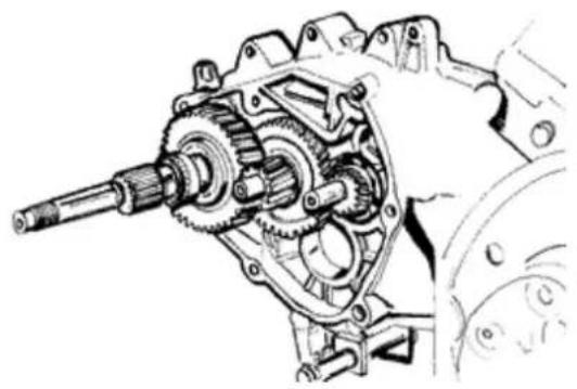
natural_image
Technical line drawing of a mechanical gear assembly (no text or symbols)Refitting the ub cover
- Install a new gasket with the centring dowels.
- Seal the vent pipe gasket using black silicone sealant.
- Install the cover checking the correct position of the vent pipe.
- Place the 3 shorter screws that can be recognised by the different colour as shown in the figure.
- Fix the vent pipe support bracket using the lower short screw.
- Install the remaining 4 screws and tighten the 7 screws at the prescribed torque.
Locking torques (N*m)
Hub cover screws 24 ÷ 27
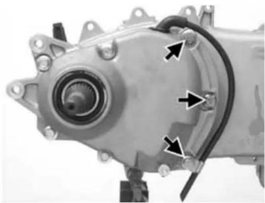
natural_image
Close-up of a mechanical component with mounting holes and wiring (no visible text or symbols)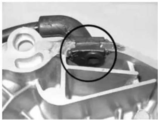
natural_image
Close-up of a mechanical component with a highlighted circular area (no visible text or symbols)Flywheel cover
Removing the hub cover
- Remove the two clamps, the two sleeves and empty the cooling system.
- Remove the 4 attachments and the flywheel cover.
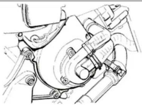
natural_image
Technical line drawing of a mechanical assembly with no visible text or symbolsRemovingBtheBstator
- Remove the oil minimum pressure switch electric terminal.
- Remove the 2 Pick-Up screws and the screw of the wiring fixing bracket, along with the 2 stator fixing screws shown in the figure.
- Remove the stator and its wires.
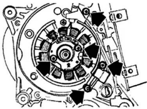
natural_image
Mechanical assembly diagram showing gear and components with directional arrows (no text or labels)RefittingBtheBstator
- Replace stator and flywheel performing the operations for removal in the reverse order and tighten the fixing screws at the prescribed torque.
- Place the wiring as shown in the figure.
- Stator and Pick-Up screws
N.B.
THEBPICK-UPBCABLEBMUSTBBEBPLACEDBBETWEEN THEBTOPBSCREWBANDBTHEBREFERENCEBDOWEL ASBSHOWNBINBTHEBFIGURE.
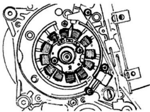
natural_image
Technical line drawing of a mechanical clutch assembly (no text or symbols)LockingBtorquesB(N*m)
StatorBcoverBscrewsB(°)B3B÷B4
RefittingBtheBflywheelCover
- Place the flywheel with the top dead centre reference aligned with the crankcase reference.
- Prepare the flywheel cover by aligning the references between drive and cover case.
- Reinstall the cover on the engine inserting the three columns in the water pump drive.
- Perform the operations for removal in the reverse order.
CAUTION
CHECKBTHEBPROPERBPOSITIONBOFBTHEBFLY-WHEELBCONNECTOR.BCHECKBTHEBPRESENCEBOF THEBTWOBCENTRINGBDOWELS.
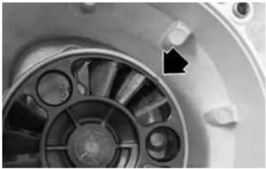
natural_image
Close-up of a mechanical fan or impeller component with a black arrow pointing to a specific part (no visible text or symbols)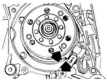
natural_image
Mechanical assembly diagram showing a circular component with bolt holes and mounting brackets (no text or labels)FlywheelBandBstarting
- Check the integrity of the internal plastic parts of the flywheel and the Pick-Up control plate.
RemovingBtheBflywheelBmagneto
- Lock the flywheel rotation using the specific tool.
- Remove the nut.
- Extract the flywheel.
CAUTION
USINGBABDIFFERENTBWRENCHBCOULDBDAMAGE THEBSTATORBCOILS.
N.B.
INBTHEBVERSIONB200BCC,BTHEBFLYWHEELBHASBA GREATERBINERTIABMASS.
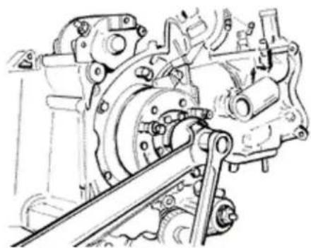
natural_image
Technical line drawing of a mechanical assembly with gears and linkages (no text or symbols)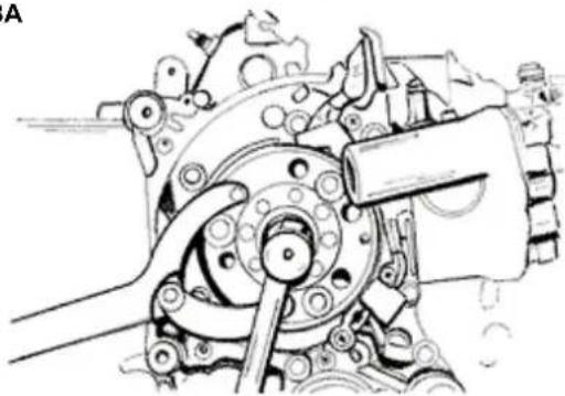
natural_image
Mechanical assembly diagram showing a motor and gear mechanism (no text or labels)InspectingBtheBflywheelBcomponents
- Check the integrity of the internal plastic parts of the flywheel and the Pick-Up control plate.
RefittingBtheBflywheelBmagneto
- Install the flywheel being careful to the proper introduction of the key.
- Tighten the flywheel nut at the prescribed torque.
- Check that the Pick-Up air gap ranges between 0.34 - 0.76 mm.
- The Pick-Up assembly requires no gap adjustment.
- Different values are caused by deformations of the Pick-Up support.
N.B.
ABVARIATIONBINBTHEBGAPBDISTANCEBCHANGES THEBMINIMUMDELIVERYBSPEEDBOFBTHEBIGNITION SYSTEM.
SpecificBtooling
020565YBCompassBflywheelBstopBspanner
LockingBtorquesB(N*m)
FlywheelBnutB54B÷B60
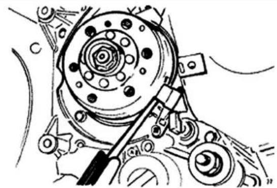
natural_image
Mechanical assembly diagram showing a rotating component with gears and levers (no text or labels)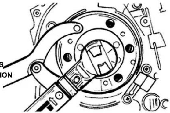
natural_image
Mechanical assembly diagram showing a clamping mechanism with no visible text or symbolsRefittingBtheBstarterBmotor
- Install a new O-Ring on the starter motor and lubricate it.
- Install the starter motor on the engine crankcase and tighten the 2 screws at the prescribed torque.
-BReplaceBtheBremainingBpartsBasBdescribedBin theBTimingBheadBcylinder,Blubrication,Bflywheel andBtransmissionBchapters.
LockingBtorquesB(N*m)
StarterBmotorBscrewsB11B÷B13
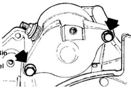
CylinderBassy.BandBtimingBsystem
RemovingBtheBintakeBmanifold
- Remove the flywheel cover as described in the Flywheel cover chapter.
- Loosen the 3 screws and remove the intake manifold.
N.B.
VERSIONB125BCCBISBPROVIDEDBWITHBANTI-TAMPERINGBSCREWS.
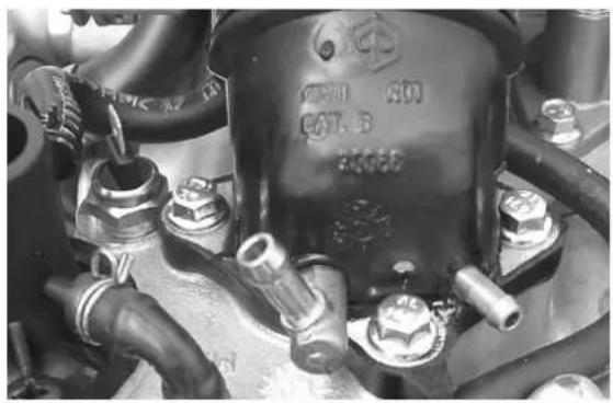
natural_image
Close-up of an engine component with visible bolts and fittings (no readable text or symbols)RemovingBtheBrocker-armsBcover
Remove the 5 screws shown in the figure
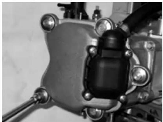
natural_image
Close-up of a mechanical component with bolts and a central black housing (no visible text or symbols)RemovingBtheBtimingBsystemBdrive
- Remove all of the parts below: transmission cover, driving pulley with belt, start-up pinion, oil sump with spring and by-pass piston, oil pump pulley cover, O-Ring on the driving shaft and pinion separating washer.
- Remove the tappet cover.
- Remove the central screw and the valve lifting mass stop bell shown in the figure.
- Remove the return spring of the automatic valve
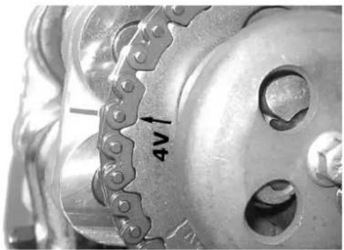
lifting mass, the valve lifting mass with relevant travel end washer.
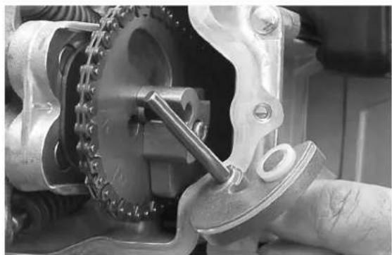
natural_image
Close-up of a mechanical assembly with chain and gear components (no visible text or symbols)- Loosen the tightener central screw.
- Remove the 2 attachments shown in the figure.
- Remove the tightener with relevant gasket.
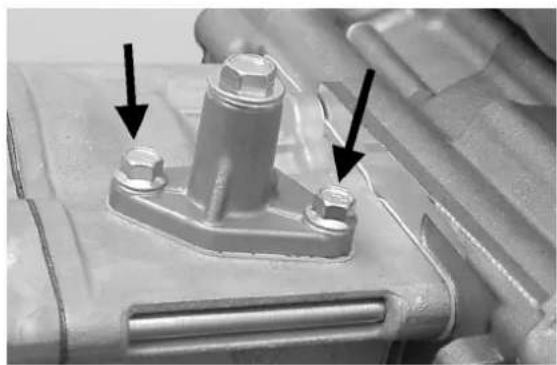
natural_image
Close-up of a mechanical component with two bolts and a central bolt, showing mounting features (no text or symbols visible)- Remove the inside hexagon screw and the balance weight shown in the figure.
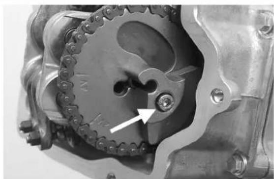
natural_image
Close-up of a mechanical gear assembly with a highlighted circular feature and an arrow pointing to a hole (no text or symbols visible)- Remove the camshaft control pulley and the relevant washer.
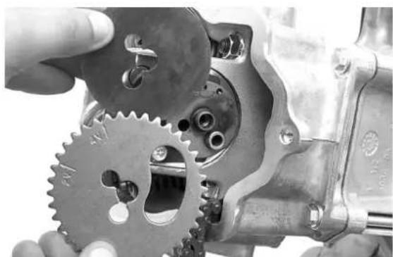
natural_image
Close-up of a hand turning a mechanical gear assembly with visible teeth and bolts (no text or symbols)- Remove the control pinion and the timing belt.
- Remove the screw shown in the figure, the spacer and the tightener sliding block.
The tightener sliding block must be removed from the transmission side. As regards the lower chain guiding sliding block, it can only be removed after the head removal.
N.B.
ITBISBADVISABLEBTOBMARKBTHEBCHAINBINBORDER TOBENSUREBTHATBTHEBINITIALBDIRECTIONBOFBROTATIONBISBMAINTAINED.
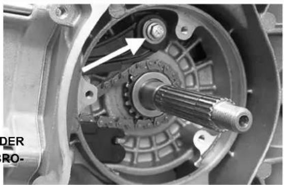
natural_image
Close-up of an internal mechanical assembly showing a shaft, rotor, and housing (no visible text or symbols)RemovingBtheBcamBshaft
- Remove the 2 screws and the camshaft fixing bracket shown in the figure.
- Remove the camshaft.
- Remove pins and rockers by the flywheel side holes.
N.B.
INBCASEBOFBNEED,BTHEBHEADBMAYBBEBREMOVED WITHBTHEBCAMSHAFT,BPINS,BROCKERSBANDBFIXINGBBRACKET.BTHEBHEADBCANBALSOBBEBRE-MOVEDBWITHOUTBREMOVINGBTHEBCHAINBAND THEBDRIVINGBSHAFTBCHAINBTIGHTENER.
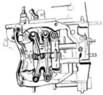
natural_image
Technical line drawing of a mechanical assembly (no visible text or symbols)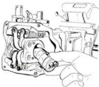
natural_image
Hand operating a mechanical component with no visible text or symbols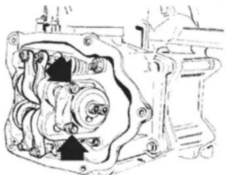
natural_image
Technical line drawing of a mechanical assembly with no visible text or symbolsRemovingBtheBcylinderBhead
- Remove the spark plug.
- Remove the 2 side attachments shown in the figure.
- Loosen the 4 head-cylinder fastening nuts in 2 or 3 times and in a crossed sequence.
- Remove the head, the 2 centring dowels and the gasket.
N.B.
INBCASEBOFBNEED,BTHEBHEADBMAYBBEBREMOVED WITHBTHEBCAMSHAFT,BPINS,BROCKERSBANDBFIXINGBBRACKET.BTHEBHEADBCANBALSOBBEBRE-MOVEDBWITHOUTBREMOVINGBTHEBCHAINBAND THEBDRIVINGBSHAFTBCHAINBTIGHTENER.
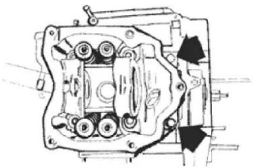
natural_image
Technical line drawing of a mechanical assembly with gears and housing (no text or symbols)RemovingBtheBvalves
- Using the specific tool with adapter, remove half-cones, plates, springs and valves.
- Remove the oil guards by the specific tool.
- Remove the lower spring supports.
CAUTION
PLACEBTHEBVALVESBSOBASBTOBRECOGNISEBTHEIR ORIGINALBPOSITIONBONBTHEBHEAD.
SpecificBtooling
020382Y011BBushingB(valveBremover)
020382YBToolBforBremovingBvalveBcotters equippedBwithBpartB012
020306YBValveBsealingBringBdrift
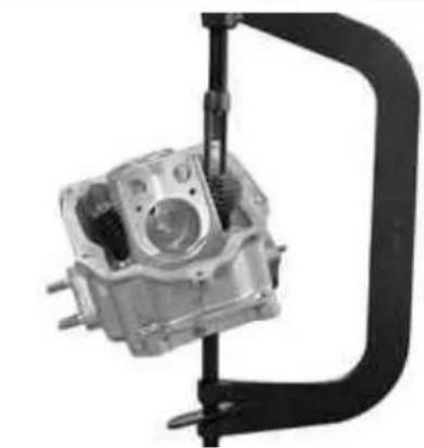
natural_image
Mechanical component with a curved handle and internal gears, no visible text or symbols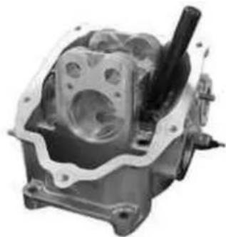
natural_image
Mechanical engine component with visible internal cavities and a shaft (no text or symbols)RemovingBtheBcylinderB-BpistonBassy.
Cylinder and piston removal
- Remove the chain guide sliding block.
- Extract the cylinder.
- Remove the cylinder base gasket.
- Remove the 2 lock rings, the pin and the piston.
- Remove the piston sealing rings.
CAUTION
BEBCAREFULBNOTBTOBDAMAGEBTHEBSEALING RINGSBDURINGBREMOVAL
N.B.
TOBPREVENTBDAMAGESBTOBTHEBPISTON,BSUPPORTBITBWHILEBREMOVINGBTHEBCYLINDER.
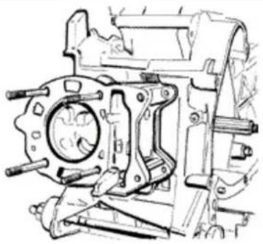
natural_image
Technical line drawing of a mechanical assembly with gears and shafts (no text or symbols)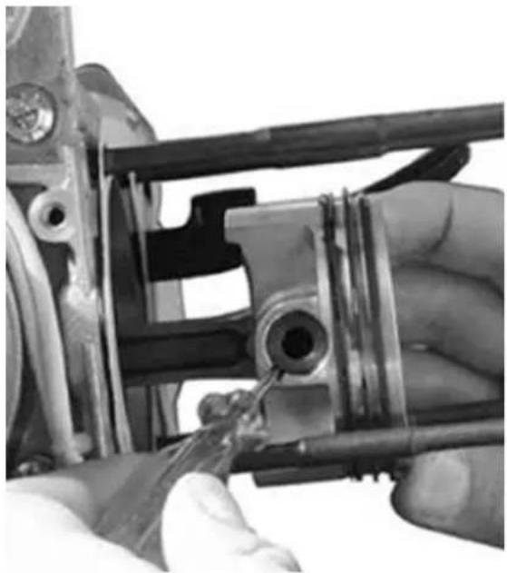
natural_image
Close-up of hands using a tool to adjust or install a mechanical component (no visible text or symbols)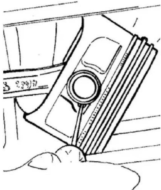
natural_image
Line drawing of a mechanical component with a circular head and ribbed base, no text or symbols presentInspectingBtheBsmallBend
- Using a micrometer, measure the connecting rod small end diameter.
N.B.
IFBTHEBCONNECTINGBRODBSMALLBENDBDIAMETER EXCEEDSBTHEBSTANDARDDBDIAMETER,BEXHIBITS WEARBORBOVERHEATING,BPROCEEDBTOBRE-PLACEBTHEBDRIVINGBSHAFT.
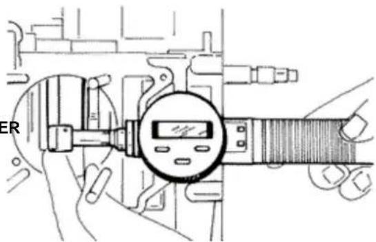
Characteristic
CheckingBtheBconnectingBrodBsmallBend:BMaximumBdiameter
15.030 mm
CheckingBtheBconnectingBrodBsmallBend: StandardBdiameter
15.015 ÷ 15.025mm
InspectingBtheBwristBpin
- Check the pin outside diameter.
- Calculate the coupling clearance between pin and connecting rod end.
- Measure the capacity diameter on the piston.
- Calculate the coupling clearance between pin and piston.
- Measure the piston outside diameter according to a direction orthogonal to the pin axis.
- Take the measurement in the position shown in the figure.
125 cc: 41.1 mm (from top) 200 cc: 5 mm (from base)
- Using a bore gauge, measure the cylinder inside diameter according to the directions shown in the figure at three different heights.
- Check that the head matching surface exhibits no deformations or wear.
Maximum admissible out of plane: 0,05 mm
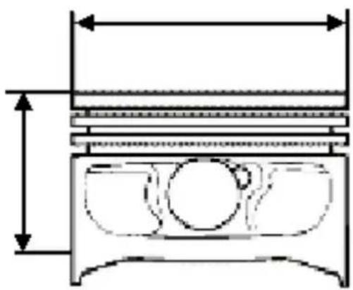
natural_image
Cross-sectional diagram of a mechanical component with internal cavities and dimension lines (no text or labels)- Pistons and cylinders are classified into categories based on their diameter. Coupling is made in pairs (A-A, B-B, C-C, D-D).
- The cylinder adjustment operation must be carried out with a finishing complying with the original angle.
- The cylinder surface must exhibit a roughness of 0.9 micron.
- This is required for ensuring a good settling of the sealing rings, thereby ensuring a low oil consumption and excellent performance.
For engine 125 cc
- There are uprated pistons for the cylinder adjustment, divided into three categories 1°, 2°, 3° equal to 0.2-0.4-0.6 mm of uprating. These are classified in the 4 categories A-A, B-B, C-C, D-D.
N.B.
THEBHOUSINGSBOFBTHEBPINBHAVEBTWOBLUBRICATIONBCHANNELS.BFORBTHISBREASONBMEASUREMENTBOFBTHEBDIAMETERBMUSTBBEBCARRIEDBOUT ACCORDINGBTOBTHEBAXISBOFBTHEBPISTON.
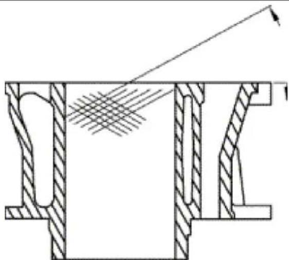
natural_image
Cross-sectional technical diagram of a mechanical assembly with hatched areas and an arrow indicating direction (no text or labels)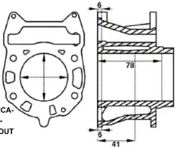
Characteristic
PistonBpinBdiameter:BStandardBdiameter:B200B-250Bcc
$$ 6 8, 9 9 0 \div 6 9, 0 1 8 $$
PistonBpinBdiameter:BStandardBdiameter:B125 cc
$$ 5 6, 9 9 7 \div 5 7, 0 2 5 $$
PistonBpinBdiameter:BPistonB200B-B250
$$ 6 8, 9 3 3 \div 6 8, 9 6 1 \mathrm{mm} $$
PistonBpinBdiameter:BPistonB125
$$ 5 6, 9 4 5 \div 5 6, 9 7 3 \mathrm{mm} $$
PistonBpinBdiameterB:BStandardBclearance
$$ 0, 0 1 5 \div 0, 0 2 9 \mathrm{mm} $$
PistonBpinBdiameterB:BStandardBdiameter
$$ 1 4, 9 9 6 \div 1 5, 0 0 0 \mathrm{mm} $$
DiameterBofBpinBseatBonBpistonB:BStandardBdia-
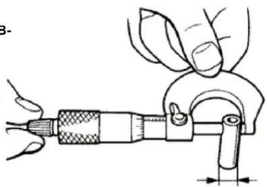
natural_image
Illustration of a hand using a micrometer to measure a tool, with no visible text or symbols.meter
15,001 ÷ 15,006 mm
DiameterBofBpinBseatBonBpistonB:BStandard clearance
0,001 ÷ 0,010 mm
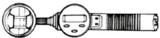
natural_image
Technical line drawing of a handheld device with a circular head and screen (no text or symbols)InspectingBtheBpiston
- Carefully clean the sealing ring housings.
- Using suitable probes, measure the coupling clearance between sealing rings and piston housings, as shown in the figure.
- If higher clearance values than those reported in the table are measured, replace the piston.
N.B.
FORBENGINEB200BCC, BMEASUREBTHEBCLEARANCE BYBINSERTINGBTHEBTHICKNESSBGAUGEBONBTHE SECONDBSEALINGBRINGBSIDE.
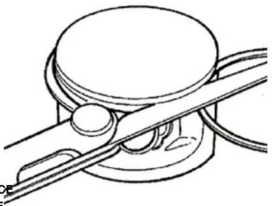
natural_image
Technical line drawing of a mechanical clamp or clamping device (no text or symbols)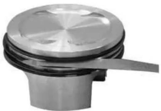
natural_image
Close-up of a metallic mechanical component with a circular top and central shaft (no visible text or symbols)125 cc
InspectingBtheBpistonBrings
Alternately insert the 3 sealing rings into the cylinder in the zone where it has the original diameter. Insert the rings in orthogonal position into the cylinder axle, using the piston.
- Measure the opening (see figure) of the sealing rings by a thickness gauge.
- If higher values than those prescribed are measured, replace the linings.
N.B.
BEFOREBREPLACINGBTHEBLININGS, BMAKEBSURE THATBTHEBPRESCRIPTIONSBRELATINGBTOBTHE SEALINGBRINGB-BHOUSINGSBANDBPISTONB-BCYLINDERBCOUPLINGBCLEARANCESBAREBRESPECTED. INBANYBCASE, BNEWBSEALINGBRINGSBCOUPLED WITHBABSECOND-HANDBCYLINDERBMAYBREQUIRE ADJUSTMENTBCONDITIONSBDIFFERENTBFROM STANDARDBONES.
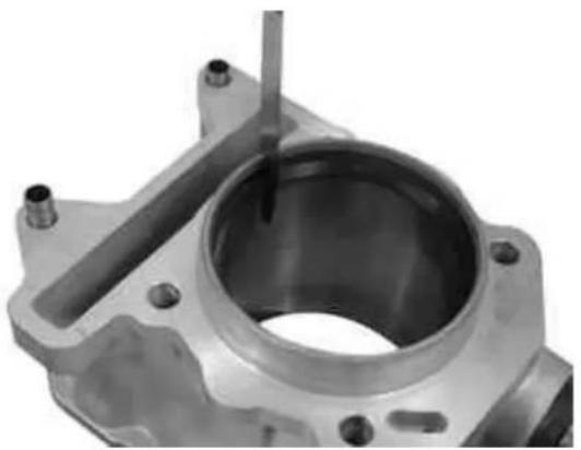
natural_image
Close-up of a metallic mechanical component with a central bore and mounting holes (no visible text or symbols)RemovingBtheBpiston
- Fit piston and pin on the connecting rod, placing the piston with the arrow towards the exhaust.
- Insert the pin locking ring into the specific tool (020430Y).
- With the opening in the position shown on the tool
S = left
D = right
- Move the locking ring into position by the punch.
- Install the pin lock using the pin shown in the figure.
CAUTION
USINGBABHAMMERBMAYBDAMAGEBTHEBLOCK HOUSINGS
N.B.
THEBTOOLBFORBINSTALLINGBTHEBLOCKINGBRINGS MUSTBBEBUSEDBMANUALLY.
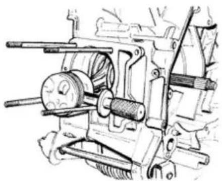
natural_image
Technical line drawing of a mechanical assembly with gears and shafts (no text or symbols)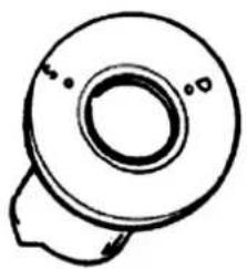
natural_image
Simple line drawing of a mechanical component with no text or symbolsSpecificBtooling
020430YBPinBretainersBinstallationBtoolB(Engine 125cc)
020454YBPinBretainersBinstallationBtool
ChoosingBtheBgasket
- Temporarily fit the cylinder on the piston, without installing the gasket;
- Set up the dial gauge on the special tool.
Support for piston recess/projection measurement: 020428Y
- Zero the dial gauge and install it onto the support rested on a rectified surface. Maintaining the zeroing position, fit the tool on the cylinder using the two supplied nuts as shown in the figure.
- Twist the crankshaft up until the TDC (where the dial gauge index rotation is inverted)
- Position the dial gauge on top of the piston, as shown in the figure, and measure the piston recess/projection.
- Using the table reproduced in the specifications chapter, select the cylinder base gasket thickness to be used for refitting. Selecting the correct gas-ket thickness, guarantees the preservation of the prescribed compression ratio.
- Remove the specific tool and the cylinder.
N.B.
ONBTHEB125CCBENGINE, BMEASUREBTHEBPISTON PROJECTION; BONBTHEB200CCBENGINE, BITSBRECESS.
SeeBalso
Slot packing system
Slot packing system
Slot packing system
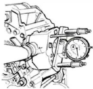
natural_image
Technical line drawing of a mechanical device with dual-tier gauge and lever mechanism (no text or symbols)Slot packing system
RefittingBtheBpistonBrings
- Place the scraper ring spring on the piston.
- Install the scraper ring keeping the opening opposed to the spring junction and with the writing "top" facing upwards. In any case, the chamfering must be arranged towards the piston top.
- Fit the 2nd sealing lining with the identification letter or the writing "top" facing the piston top. In any case, the step must be facing opposite the piston top.
- Fit the first sealing lining with the top writing or the reference facing the piston top.
- Misalign the lining openings at 120^ as shown in the figure.
- Lubricate the parts with engine oil.
- The engine 200cc uses the first compression lining with an L section.
N.B.
THEB2BSEALINGBLININGSBHAVEBABCONICALBSURFACEBOFBCONTACTBWITHBTHEBCYLINDER.BTHISBISTOBENSUREBABBETTERBADAPTATION.
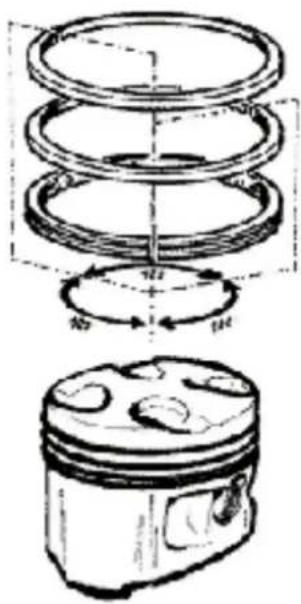
125

natural_image
Technical drawing of two mechanical components with hatched areas indicating material sections (no text or symbols)RefittingBtheBcylinder
- Insert the cylinder base gasket with the thickness determined above.
- Using the fork and the band clamp, install the cylinder as shown in the figure.
N.B.
BEFOREBINSTALLINGBTHECYLINDER,BCARE-
FULLYBBLOWBTHEBLUBRICATIONBDUCTBANDBLUBRICATEBTHEBCYLINDERBLINER.
SpecificBtooling
020393YBPistonBbandBclampsB(EngineB200B-250Bcc)
020287YBPistonBbandBclampsB(EngineB125cc)
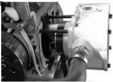
natural_image
Close-up of mechanical components including gears and a housing, with no visible text or symbols.InspectingBtheBcylinderBhead
- Using a rectified bar and a thickness gauge, check that the head surface exhibits no deformations or wear.
- Check that the camshaft and the rocker pin capacities exhibit no wear.
- Check that the head cover, the exhaust manifold and the intake manifold surface exhibits no wear.
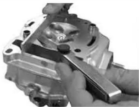
natural_image
Close-up of a hand using a tool to adjust or install a mechanical component (no visible text or symbols)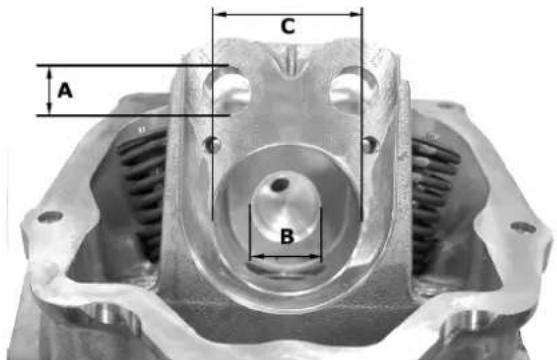
InspectingBtheBtimingBsystemBcomponents
- Check that the guide sliding block and the tightening sliding block are not too worn.
- Check that the camshaft and pinion control pulley chain unit exhibit no wear.
- In case of wear, replace the parts. In case of wear of the chain, pinion and pulley, replace the entire unit.
- Remove the central screw with the washer and
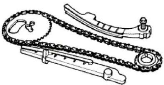
natural_image
Technical line drawing of a chain drive mechanism (no text or symbols)the tightener spring. Check that the unidirectional gear is not worn.
- Check the integrity of the tightener spring.
- In case of wear, replace the entire assembly.
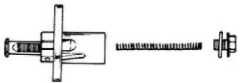
natural_image
Technical line drawing of a mechanical assembly with threaded fastener and bolted head (no text or symbols)Inspecting the valve sealings
- Insert the valves into the head.
- Alternately test the intake and exhaust valves.
- The test should be carried out by filling the manifold with fuel and checking that the head does not bleed from the valves, when pressed by your fingers only.
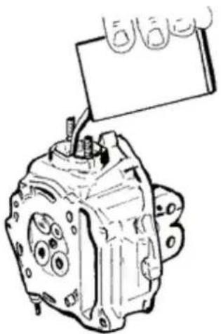
natural_image
Technical line drawing of a mechanical component with no visible text or symbolsInspecting the valve housings
- Check the width of the impression on the valve seat «V»; max wear limit 1.6 mm.
- Clean the valve guides of any carbon residues.
- Measure the inside diameter of each valve guide.
- Measure according to the rocker thrust direction at three different heights.
- If the valve seat impression width or the valve guide diameter are larger than the prescribed values, replace the head.
Characteristic
Wear of valve seats: Intake guide
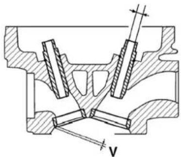
Admissible limit: 5.022
WearBofBvalveBseats:BIntakeBguide
Standard diameter: 5.000 ÷ 5.012 mm
WearBofBvalveBseats:BExhaustBguide
Admissible limit 5.022
WearBofBvalveBseats:BExhaustBguide
Standard diameter: 5.000 ÷ 5.012 mm
InspectingBtheBvalves
- Check the valve stem diameter at the three points shown in the figure.
- Calculate the clearance between valve and valve guide.
- Check that the contact surface with the articulated register terminal is free from wear.
- If the checks above give no failures, you can use the same valves. To obtain better sealing performance, grind the valve. Perform this operation carefully using fine grain emery paste. While grinding, keep the head with the valve axes in horizontal position to prevent the emery paste residues from penetrating into the valve guide stem coupling (see figure).
CAUTION
TOBPREVENTBSCRATCHINGBTHEBCONTACTBSURFACE,BDOBNOTBFORCEBTHEBVALVEBROTATION WHENBTHEBEMERYBPASTEBFINISHES.BCAREFULLY CLEANBTHEBHEADBANDBTHEBVALVESBUSINGBA SUITABLEBPRODUCTBFORBTHEBTYPEBOFBEMERY PASTEBUSED.
N.B.
DOBNOTBCHANGEBTHEBVALVEBASSEMBLYBPOSITION.
Characteristic
ValveBcheck:BstandardBlength
Exhaust: 94.4 mm
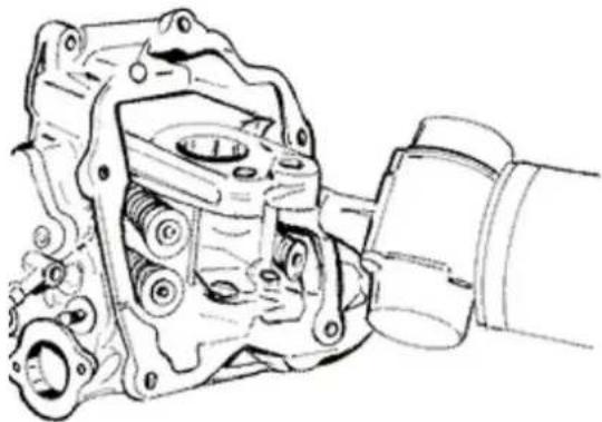
natural_image
Technical line drawing of a mechanical assembly with gears and housing (no text or symbols)Valve check: standard length
Intake: 94.6 mm
Valve check: maximum admissible clearance
Exhaust: 0.072 mm
Valve check: maximum admissible clearance
Intake: 0.062 mm
Valve check: standard clearance
Exhaust: 0.025 ÷ 0.052 mm
Valve check: standard clearance
Intake: 0.013 ÷ 0.040 mm
Valve check: minimum admissible diameter
Exhaus: 4.95 mm
Valve check: minimum admissible diameter
Intake: 4.96 mm
Valve check: standard diameter
Intake: 4.972 ÷ 4.987 mm
Valve check: standard diameter
Exhaust: 4.96 ÷ 4.975 mm
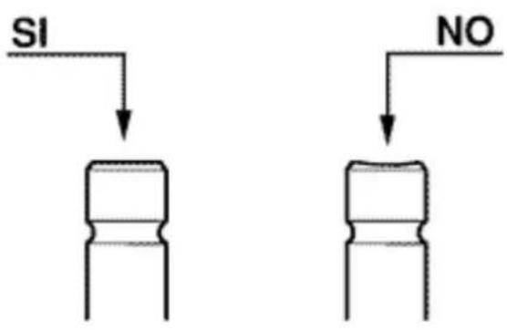
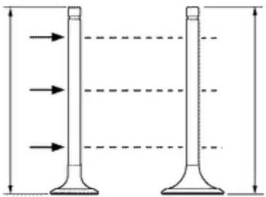
natural_image
Diagram of two vertical flutes with horizontal dashed lines indicating measurement or alignment (no text or symbols)InspectingBtheBspringsBandBhalf-cones
- Check that the spring upper support plates and half-cones are free from irregular wear.
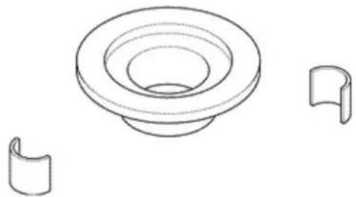
natural_image
Technical line drawing of a mechanical component with a circular top and two separate views (no text or symbols)RefittingBtheBvalves
- Lubricate the valve guides with engine oil.
- Place the valve spring rests on the head.
- Using the specific punch, insert the 4 sealing rings alternately.
- Insert valves, springs and plates. Using the specific tool provided with the special adapter, compress the springs and insert the half-cones into the relevant seats.
N.B.
DOBNOTBCHANGEBTHEBVALVEBASSEMBLYBPOSITION.BFITBTHEBVALVESBWITHBTHEBREFERENCE COLOURBONBTHEBHALF-CONESBSIDEB(LARGER STEPBCURLS).
SpecificBtooling
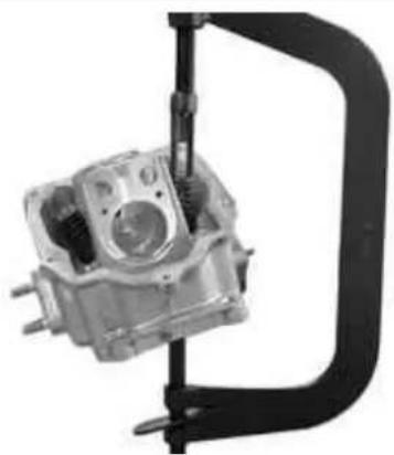
natural_image
Mechanical component with a curved handle and cylindrical housing (no visible text or symbols)020306YBValveBsealingBringBdrift
020382YBToolBforBremovingBvalveBcotters equippedBwithBpartB012
020382Y011BBushingB(valveBremover)
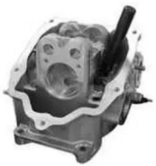
natural_image
Mechanical engine component with visible internal cavities and a shaft (no text or symbols)InspectingBtheBcamBshaft
- Check that the camshaft ends exhibit no abnormal wear.
- Measure the cam height.
- Check that the groove and relevant retain plate are free from wear.
- If different values or wear than those prescribed are found, replace the faulty parts.
- Check that the automatic valve lifting device cam, the travel end roller and the rubber abutment on the containment bell are free from wear.
- Check that the valve lifting spring has not yielded.
- In case of wear, replace the worn parts.
- Check that the rocker pins exhibit no scratches or wear.
- Measure the inside diameter of each rocker.
- Check that the cam contact sliding block and the articulated register plate is free from wear.
Characteristic
CamshaftBcheck:BStandardBdiameter
∅ 12.000 ÷ 12.011 mm
CamshaftBcheck:BStandardBdiameter
∅ 11.977 ÷ 11.985 mm
CamshaftBcheck:BMaximumBadmissibleBaxial clearance
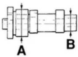
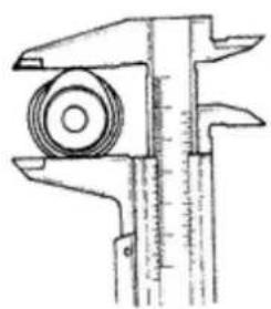
natural_image
Technical line drawing of a vernier caliper (no text or symbols)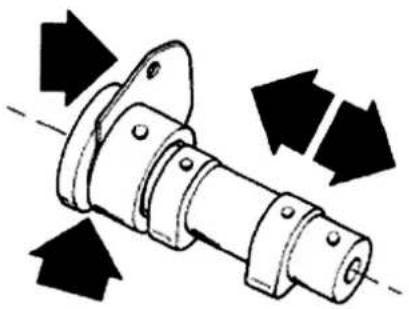
natural_image
Mechanical component diagram showing directional arrows indicating motion or force (no text or symbols)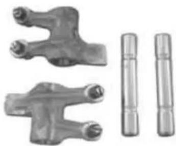
natural_image
Two metallic mechanical components with threaded ends, shown alongside two separate cylindrical shafts (no text or symbols visible)0.42 mm
Camshaft check: Standard axial clearance
0.11 ÷ 0.41 mm
Camshaft check: Standard height
Exhaust: 29.209 mm
Camshaft check: Standard height
Intake: 30.285 mm
Camshaft check: Minimum admissible diameter
Connection B ∅: 19.950 mm
Camshaft check: Minimum admissible diameter
Connection A ∅: 36.94 mm
Camshaft check: Standard diameter
Connection B ∅: 19.959÷ 19.98 mm
Camshaft check: Standard diameter
Connection A ∅: 36.95÷ 36.975 mm
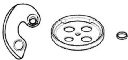
natural_image
Line drawings of mechanical parts including a curved handle, a circular component with holes, and a washer (no text or symbols)Refitting the head and timing system components
Install the timing chain control pinion on the driving shaft with the chamfering facing the introduction side.
- Insert the timing control chain on the driving shaft.
- Insert the tightener sliding block on the head side.
- Install the spacer with the fixing screw.
- Tighten the screw at the prescribed torque.
Locking torques (N*m)
Sliding block screw 10 ÷ 14 Nm
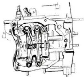
natural_image
Technical line drawing of a mechanical assembly (no visible text or symbols)Install pins and rockers.
- Lubricate the 2 rockers through the top holes.
- Lubricate the 2 connections and insert the camshaft into the head with the cams opposite the
rockers.
- Insert the retain plate and tighten the 2 screws shown in the figure at the prescribed torque.
LockingBtorquesB(N\*m)
PlateBscrewsB4÷6BNm
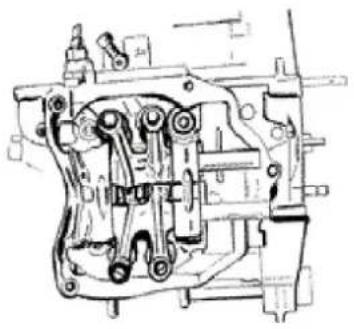
natural_image
Technical line drawing of a mechanical assembly (no visible text or symbols)Insert the spacer on the camshaft.
- Place the piston on the top dead centre using the references between flywheel and engine crankcase.
- Keeping this position, insert the chain on the camshaft control pulley.
- Insert the pulley on the camshaft keeping the reference 4V at the reference point obtained on the head.
- Install the balance weight with its fixing screw and tighten at the prescribed torque.
LockingBtorquesB(N\*m)
BalanceBweightBscrewB7÷8,5BNm
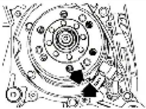
natural_image
Mechanical assembly diagram showing concentric circular components with no visible text or symbols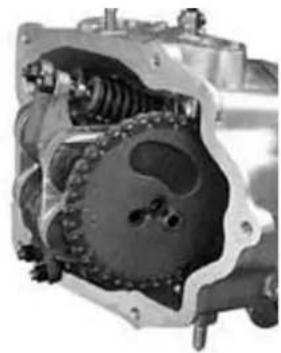
natural_image
Cross-sectional view of a mechanical assembly (no visible text or symbols)Insert the travel end ring on the valve lifting mass and mount the valve lifting cam on the camshaft.
N.B.
LUBRICATEBWITHBGREASEBTHEBTRAVELBEND RINGBTOBPREVENTBACCIDENTALBLEAKSBWITH CONSEQUENTBDROPPINGBINTOBTHEBENGINE.
- Install the valve lifter return spring. During this operation, the spring must be loaded by about 180^ .
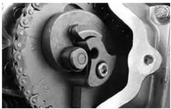
natural_image
Close-up of mechanical components including a chain and gear assembly (no visible text or symbols)Install the containment bell using the balance
weight fixing screw as a reference.
- Tighten the central fixing screw at the prescribed
torque.
Locking torques (N*m)
Containment bell screw 11÷15 Nm
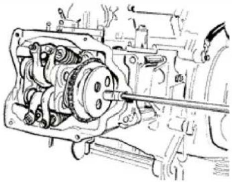
natural_image
Technical line drawing of a mechanical assembly with gears and shafts (no text or symbols)Set the tightener cursor to the rest position.
- Install the tightener on the cylinder using a new gasket and tighten the 2 screws at the prescribed torque.
Insert the spring with the central screw and the washer and tighten the cap at the prescribed torque.
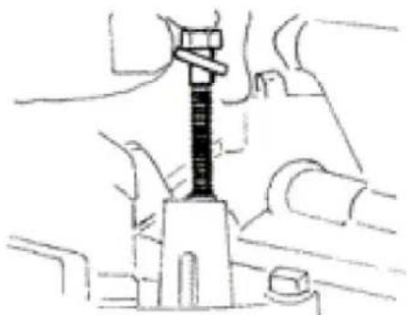
natural_image
Technical line drawing of a mechanical assembly with no visible text or symbolsLocking torques (N*m)
Tightener screws 11÷13 Nm Tightener cap 5÷6 Nm
Adjust the valve clearance
- Install the spark plug.
Electrode distance: 0.8 mm
Locking torques (N*m)
Spark plug 12÷14 Nm
Replace the head cover and tighten the 5 screws at the prescribed torque. Check the proper position of the gasket.
Replace the flywheel cover as already described in the flywheel chapter.
- Replace the oil pump control, the chain compartment cover, the by-pass and the oil sump as described in the Lubrication chapter.
- Replace the driving pulley, the belt and the transmission cover as described in the Transmission chapter.
Locking torques (N*m)
Tappet cover screws 6÷7 Nm
REFITTING THE TIMING SYSTEM COMPONENTS
NameBTorqueBinBNm
| Tappet cover screws,6÷7 Nm | |
| Spark plug,12÷14 Nm | |
| Tightener cap,5÷6 Nm | |
| Tightener screws,11÷13 Nm | |
| Containment bell screw,11÷15 Nm | |
| Balance weight screw,7÷8,5 Nm | |
| Plate screws,4÷6 Nm | |
| Sliding block screw | 10 ÷ 14 Nm |
- Insert the timing chain guide sliding block.
- Insert the centring dowels between head and cylinder, install the head gasket and the head on the cylinder.
- Lubricate the stud bolt threading
- Tighten the nuts at a preliminary torque of 7 ± 1 N·m
- Turn by an angle of 180^ (2 turns by 90^ each) To perform the above operations, follow the tightening sequence shown in the figure.
- Install the two screws on the timing chain side and tighten at the prescribed torque.
N.B.
BEFOREBINSTALLINGBTHEBHEAD, BMAKEBSURE THATBTHEBLUBRICATIONBCHANNELBISBCLEANBUSINGBABCOMPRESSEDBAIRBJET.
LockingBtorquesB(N*m)
TimingBbeltBtightenerBsupportBscrewB11B÷B13
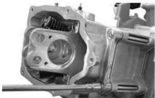
natural_image
Close-up of a mechanical assembly showing internal components and housing (no visible text or symbols)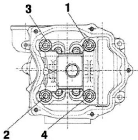
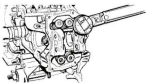
natural_image
Technical line drawing of a mechanical assembly with no visible text or symbolsRefittingBtheBrocker-armsBcover
- Reassemble the head cover by locking the 5 screws to the prescribed torque.
- Pay attention to correct positioning of the gas- ket.
LockingBtorquesB(N*m) TappetBcoverBscrewsB6÷7BNm
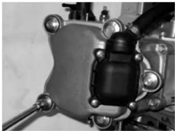
natural_image
Close-up of a mechanical component with bolts and a central black housing (no visible text or symbols)RefittingBtheBintakeBmanifold
- Install the intake manifold and tighten the 3 screws.
N.B.
FORBTHEBSPECIALBSCREWSBOFBVERSIONB125CC USEBINSERTSBANDBINSERTBHOLDERSBAVAILABLE ONBTHEBMARKET.
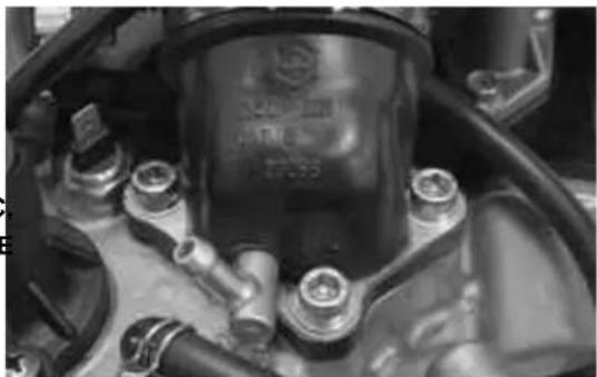
natural_image
Close-up of a mechanical engine component with bolts and housing (no visible text or symbols)CrankcaseB-Bcrankshaft
SplittingBtheBcrankcaseBhalves
Remove the following assemblies: transmission cover, driving pulley, driven pulley and belt, rear hub cover, gears, bearings and oil guards as described in the Transmission chapter.
- Remove the oil sump, the by-pass, the chain compartment cover, the oil pump as described in the LubricationBchapter.
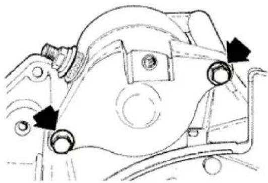
natural_image
Technical line drawing of a mechanical component with arrows indicating motion or assembly (no text or symbols)Remove the flywheel cover with water pump, the flywheel, the stator as described in the Magneto flywheelBchapter.
- Remove the oil filter and the oil pressure switch.
- Remove the cylinder-piston-head unit as described in the Timing head cylinder chapter.
- Remove the 2 screws shown in the figure and the starter motor.
Before opening the engine crankcase, check the driving shaft axial clearance. To this purpose, use a plate and a support with specific comparator tool.
Higher clearance denotes wear of the crankcase driving shaft rest surfaces.
Standard clearance: 0.15 ÷ 0.40 mm
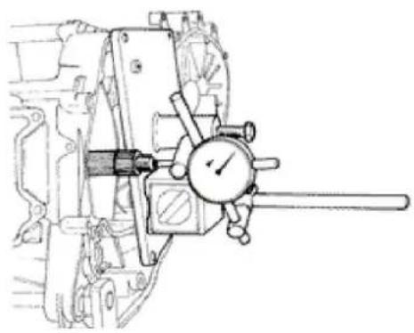
natural_image
Technical line drawing of a mechanical device with a dial indicator (no text or symbols)Remove the 11 crankcase coupling screws.
- Split the crankcases while keeping the driving shaft inserted on one of the 2 half-crankcases.
Remove the driving shaft.
N.B.
THEBDRIVINGBSHAFTBOFBTHEBVERSIONB200BCCBIS INSTALLEDBWITHBTWOBSTEELBREPHASINGBWASHERS.BNOTEBTHEBASSEMBLYBPOSITION.
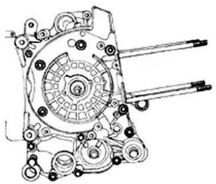
natural_image
Technical line drawing of a mechanical assembly with gears and shafts (no text or symbols)CAUTION
FAILUREBTOBOBSERVEBTHISBRULEBCANBCAUSE THEBACCIDENTALBDROPBOFBTHEBDRIVINGBSHAFT.
- Remove the crankcase gasket.
- Remove the two screws and the internal cover shown in the diagram.
CAUTION
WHILEBOPENINGBTHEBCRANKCASESBANDBREMOVINGBTHEBDRIVINGBSHAFT,BCHECKBTHATBTHESHAFTBTHREADEDBENDSBDOBNOTBINTERFERE WITHBTHEBBENCHBBRASSES.BFAILUREBTOBOBSERVEBTHISBPRECAUTIONBCANBDAMAGEBTHEBENCHBBRASSES.
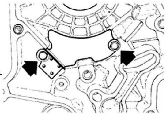
natural_image
Mechanical assembly diagram showing gear and housing components with two black arrows indicating specific parts (no text or labels present)- Remove the oil seal on the flywheel side.
- Remove the oil filter union shown in the diagram.
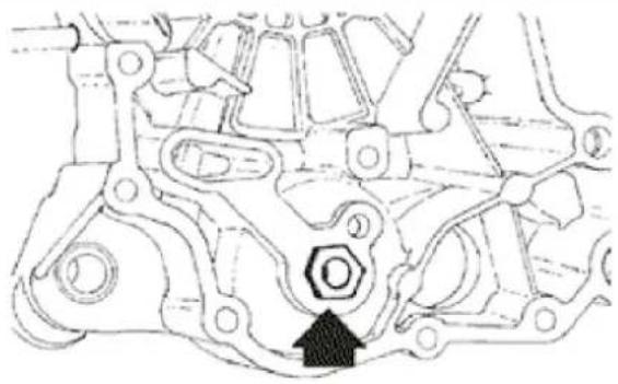
natural_image
Mechanical assembly diagram showing interconnected components with no visible text or symbolsFittingBclearance
RodBaxialBclearanceB0.20B-B0.50
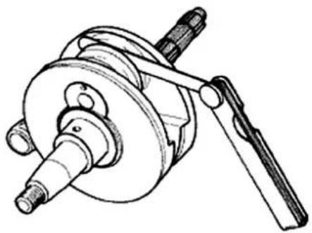
natural_image
Technical line drawing of a mechanical assembly with a shaft and housing (no text or symbols)Check the connecting rod radial clearance.
Standard clearance: 0.036 ÷ 0.054 mm
- Check that the axial clearance containment surfaces exhibit no scratches; using a gauge, check the driving shaft width as shown in the figure.
Standard measures:
55.75 ÷ 55.90 mm (125 cc)
51.40 ÷ 51.45 mm (200 cc)
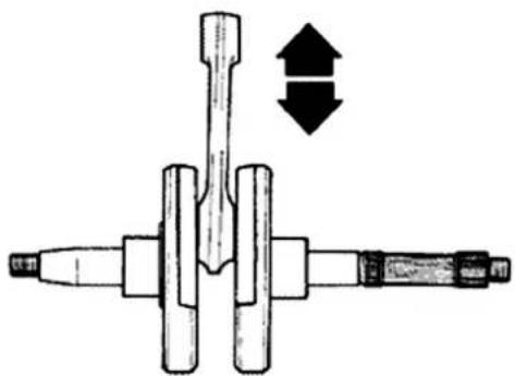
natural_image
Mechanical assembly diagram showing a central pin with two arrows indicating direction (no text or symbols)N.B.
THEBDRIVINGBSHAFTBCANBBEBREUSEDBWHENBTHE WIDTHBFALLSBWITHINBTHEBSTANDARDDBVALUES ANDBTHEBSURFACESBAREBFREEBFROM SCRATCHES.
The driving shaft can be reused when the width falls within the standard values and the surfaces are free from scratches.
Shim adjustments (only 200 cc)
- Check the shim adjustment thickness.
Standard thickness: 2.175 ÷ 2.225 mm
- Check that shim adjustments are free from scratches.
N.B.
INBCASEBOFBREUSE, BKEEPBTHEBINITIALBASSEMBLYBPOSITION.
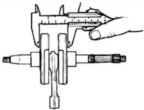
natural_image
Illustration of a hand using a vernier caliper to measure a mechanical component (no text or symbols present)If the driving shaft - crankcase axial clearance is higher than the standard value and the driving shaft exhibits no irregularity, the problem is caused by wear or by a wrong machining on the engine crank-case
Check the diameters of both the driving shaft ends according to the axes and planes shown in the figure. Half-shafts are classified into two categories, Cat. 1 and Cat. 2. The table is shown below.
Characteristic
StandardBdiameterB(125B-B200)BCat.B2
29.004 ÷ 29.010
Cat.B1B-BStandardBdiameterB(125-200)Bevo
28.994 ÷ 29.000
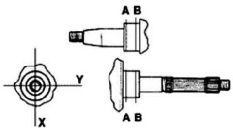
STANDARDDBDIAMETER
SpecificationBDesc./Quantity
| Standard diameter (125 - 200) Cat. 2 | 29.004 ÷ 29.010 |
| Cat. 1 - Standard diameter (125-200) evo | 28.994 ÷ 29.000 |
InspectingBtheBcrankshaftBalignment
To install the drive shaft on the support and to measure the misalignment in the 4 points indicate to you in figure.
- Check that the driving shaft cone, the tab seat, the oil guard connection and the threaded tangs are in good working order.
- In case of failures, replace the driving shaft.
The connecting rod head brasses cannot be replaced.
For the same reason, when cleaning the driving shaft, be careful to prevent any impurity from entering into the shaft lubrication hole.
In order to prevent damaging the connecting rod brasses, do not attempt cleaning the lubrication duct with compressed air.
- Make sure that the 2 pads on the crank button are properly mounted.
- A wrong installation of a pad can seriously affect the brass lubrication pressure.
N.B.
BENCHBENDSBAREBNOTBRECTIFIABLE.
SpecificBtooling
020074YBCrankshaftBaligningBtool
Characteristic
AlignmentBcheck:BMaxBadmissibleBdisplacement:
AB=0.15 mm
BB=0.01 mm
CB=0.01 mm
DB= 0.10 mm
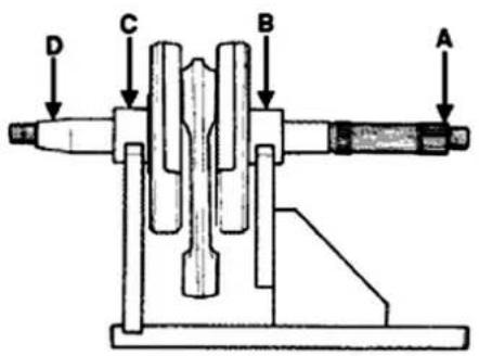
Measure the diameters on both X, and Y axes.
SpecificBtooling
020074YBCrankshaftBaligningBtool
CHECKINGBTHEBCRANKSHAFTBALIGNMENT
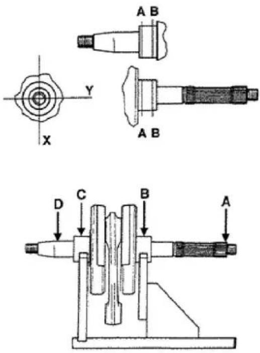
Inspecting the crankcase halves
- Before checking the crankcase, carefully clean all lubrication channels and surfaces.
- For the transmission side half-crankcase, especially clean the compartment and the channels of the oil pump, the by-pass duct, the bench brasses and the cooling jet on the transmission side, see figure.
As already described in the Lubrication chapter, it is especially important that the by-pass housing is free from wear that may impair the proper sealing of the lubrication pressure adjustment piston.
- For the half-crankcase on the transmission side, especially clean the lubrication channels of the bench brasses, the head oil feeding jet channel, the drainage channel for the oil guard on the fly-wheel side.
- Check that the surfaces are free from dents or deformations, with special attention to the crank-
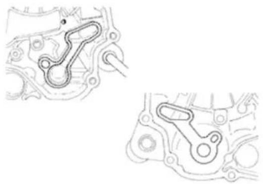
natural_image
Technical line drawing of mechanical components with no visible text or symbols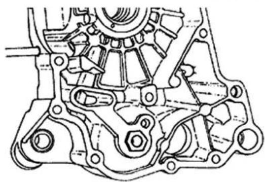
natural_image
Technical line drawing of a mechanical gear assembly (no text or symbols)case coupling and the crankcase-cylinder surfaces.
- Any defects in the crankcase gasket or on the surfaces indicated in the figure can cause pressurised oil leaks, thereby affecting the connecting rod and bench brass lubrication pressure.
- Check that the driving shaft axial clearance containment surfaces are free from wear. For the dimensional check, refer to the instructions relating to the axial clearance and dimensions check on the driving shaft.
N.B.
THEBHEADBLUBRICATIONBCHANNELBISBPROVIDED WITHBABSHUTTERBJET;BTHISBGIVESBAB«LOWBPRES-SURE»BHEADBLUBRICATION;BTHISBCHOICEBWAS MADEBTOBREDUCEBTHEBOILBTEMPERATUREBIN THEBSUMP.BTHEBJETBCLOGGINGBIMPAIRSBTHE HEADBLUBRICATIONBANDBTHEBTIMINGBMECHAN-ISMS.BABJETBFAILUREBCAUSESBABDECREASEBOF THEBBENCHBBRASSBANDBCONNECTINGBRODBLUB-RICATIONBPRESSURE.
N.B.
THEBJETBISBFEDBTHROUGHBTHEBBENCHBBRASSES. PROPERBOPERATIONBOFBTHISBCOMPONENTBIM-PROVESBTHEBPISTONBTOPBCOOLING.BCLOGGING HASBEFFECTSBTHATBAREBDIFFICULTBTOBDETECT (PISTONBTEMPERATUREBINCREASE).BFAILUREBOR LEAKBCANBCONSIDERABLYBDECREASEBTHE BENCHBBRASSBANDBCONNECTINGBRODBLUBRICATIONBPRESSURE.
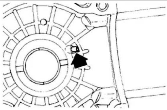
natural_image
Technical line drawing of a mechanical component with no visible text or symbolsInspectingBtheBcrankshaftBplainBbearings
- To obtain a proper lubrication of the brasses, it is necessary to have an optimum lubrication pressure (3,2 bar) and a good oil rate; to this purpose, the brasses must be placed properly, so as to not have shuttering in the oil feeding channels. - Bench brasses are realised with 2 half-bearings, one of which is solid while the other has holes
and seats for lubrication.
- The solid half-bearing is intended to stand the thrusts caused by combustion, and for this reason it is arranged opposed the cylinder.
- To prevent shutters in the oil feeding channels, the matching surface of the two half-bearings must be perfectly orthogonal to the cylinder axis, as shown in the figure.
- The oil feeding channel section is also affected by the brass driving depth relative to the driving shaft axial clearance containment plane.
- Check the brass diameter in the 3 directions shown in the figure.
- Repeat the measurements for the other half of the brass. See figure.
- The crankcase is supplied in three setup versions: with RED brasses, with BLUE brasses and with YELLOW brasses.
- The brass housing hole is in the only category reported below.
- The standard brass diameter after driving is variable on the basis of a coupling selection.
- The brass seats into the crankcases are classified into 2 categories as for the driving shaft Cat. 1 and Cat. 2.
- Brasses are divided into 3 categories according to their thickness. See the table below:
TYPEBIDENTIFICATION
| A,RED |
| B,BLUE |
| C,YELLOW |
TypeB"A" TypeB"B" TipoB"C"B-
-BRED -BBLUE YELLOW
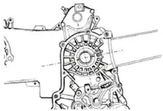
natural_image
Technical line drawing of a mechanical assembly with no visible text or symbols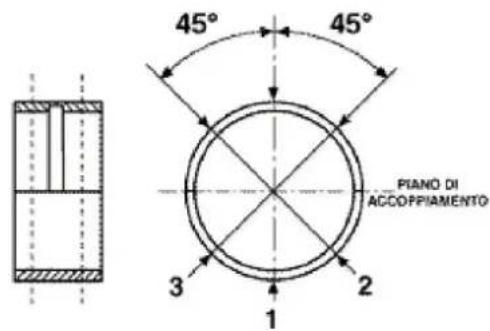
| BenchBhalf-bearing | 1,970 ÷ 1,973 | 1,9703 ÷ 1,976 | 1,976 ÷ 1,979 | |
| Brass cat-egory | Half-crank-caseBcat-egory | BrassBinside diameterBafter reassembly | PossibilityBofBas-sembly | |
AB1,29,025 ÷ 29,040,Original
BB1,29,019 ÷ 29,034,Original
2,29,028 ÷ 29,043
andBspare
CB2,29,022 ÷ 29,037,Original
Match the shaft with two category 1 shoulders with category 1 crankcase (or cat. 2 with cat. 2). A spare crankcase cannot be combined with a driving shaft with mixed categories. Spare shafts have half-shafts of the same category.
| Half-crankcaseBEngineBhalf-shaft | Brass |
| Cat.1,Cat.1,B | |
| Cat.2,Cat.2,B | |
| Cat.1,Cat.2,A | |
| Cat.2,Cat.1,C |
N.B.
TOBKEEPBSUCHBPOSITIONBOFBTHEBBRASSESBON THEBCRANKCASE,BDRIVINGBISBFORCEDBONBSTEEL RINGSBINSETEDBINBTHEBCASTINGBOFBBOTH HALF-CRANKCASES.
N.B.
DOBNOTBTAKEBTHEBMEASUREBONBTHEBHALF-BEARINGBMATCHINGBSURFACEBSINCEBTHEBENDS AREBRELEASEDBTOBALLOWBDEFORMATIONBUPON INSERTION.
N.B.
SPAREBCRANKCASESBAREBSELECTEDBWITH HALF-CRANKCASESBOFBTHEBSAMEBCATEGORY ANDBMOUNTEDBWITHBCATEGORYBBBBBRASSES (BLUEBCOLOURED).
Characteristic
StandardBdrivingBdepth
1.35 - 1.6
CrankcaseBdiameterBwithoutBbrass
32,953 ÷ 32,963
Lubrication
ConceptualBdiagrams
LUBRIFICATION CIRCUIT
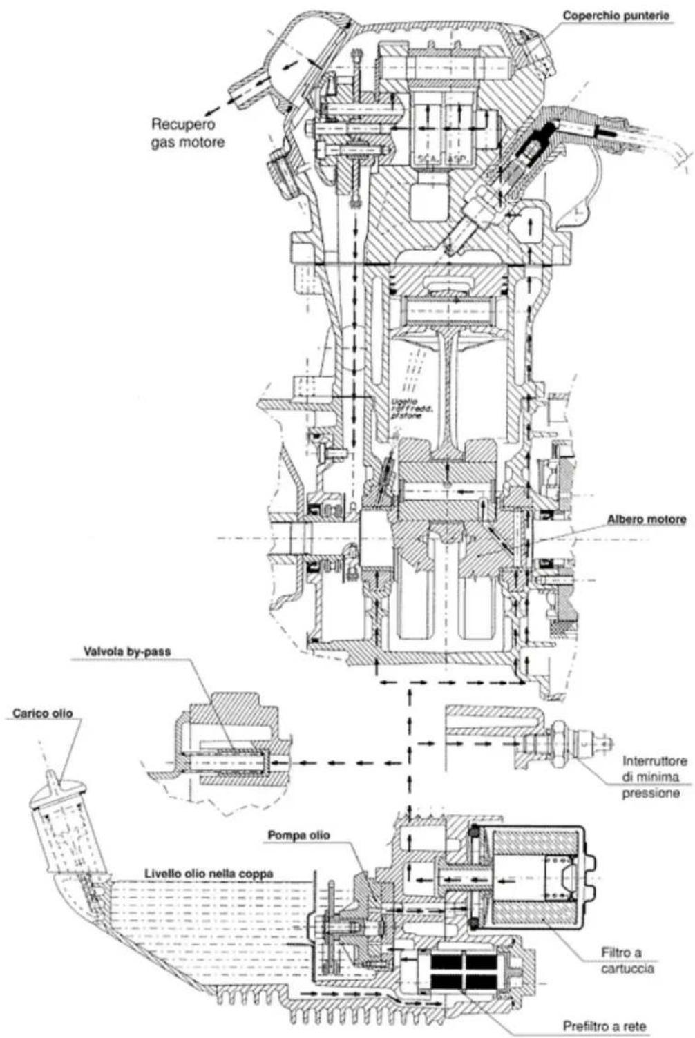
Oil pressure check
- After removing the flywheel cover as explained in the Flywheel chapter, disconnect the minimum
oil pressure switch electric connection and remove the switch.
- With engine at 1,650 rpm, and with oil at a temperature of 90^ , check that oil pressure ranges between 0.5 - 1.2 atm.
- With engine at 6000 rpm, and with oil at a temperature of 90^ , check that oil pressure ranges between 3.2 - 4.2 atm.
- After the check, remove the specific tools mounted on the engine, replace the oil pressure switch and the washer and lock at the prescribed tightening torque, then install the flywheel cover.
- In case of non-conforming pressure, check the oil filter, the by-pass, the oil pump and the seals on the driving shaft in a sequence.
N.B.
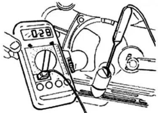
natural_image
Illustration of a hand using a multimeter to test electrical components (no text or symbols visible)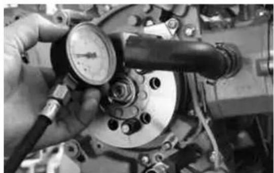
natural_image
Close-up of a hand adjusting a mechanical valve and pressure gauge in a vehicle (no visible text or symbols)THEBCHECKBMUSTBBEBCARRIEDBOUTBWITHBOILBAT THEBCORRECTLEVELBANDBWITHBANBOILBFILTER INBGOODBCONDITIONS.
Characteristic
OilBpressure
Minimum admissible pressure at 6.000 rpm: 3.2 atm.
LockingBtorquesB(N\*m)
MinimumBoilBpressureBsensorB12B÷B14
CrankshaftBoilBseals
Refitting
- Install the inside head and tighten the 2 screws at the prescribed torque.
- Install the oil filter union and tighten at the prescribed torque.
- Place the gasket on the half-crankcase with the centring dowels on the transmission side half-
crankcase.
- Lubricate the bench brasses, insert the driving shaft on the transmission side half-crankcase.
- Couple the 2 half-crankcases.
For the version 200 cc, replace the shim adjustments in their original position.
- Install the 11 screws and tighten at the prescribed torque. - Lubricate the oil guard on the flywheel side.
- Using the specific tool, install the oil guard.
- Install a new O-Ring on the pre-filter, and lubricate it.
- Insert the pre-filter on the engine with relevant cap. Tighten at the prescribed torque.
N.B.
FAILUREBTOBUSEBTHEBTOOLBCANBCAUSEBA WRONGBDRIVINGBDEPTHBWITHHCONSEQUENT WRONGBOPERATIONBOFBTHEBOILBGUARD.
SpecificBtooling
020425YBFlywheel-sideBoilBguardBpunch
LockingBtorquesB(N\*m)
EngineBcrankcaseBinsideBheadBscrews (transmissionBsideBhalfBshaft)B4B÷B6BOilBfilter unionBonBcrankcaseB27B÷B33BEngineBcrankcase couplingBscrewsB11B÷B13BEngineBoilB/BnetBfilter drainageBcapB24B÷B30
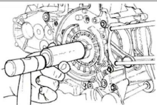
natural_image
Mechanical assembly diagram showing a shaft and gear assembly (no text or labels)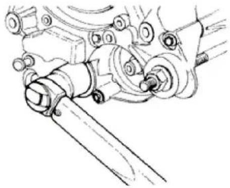
natural_image
Technical line drawing of mechanical components including gears and linkages (no text or symbols)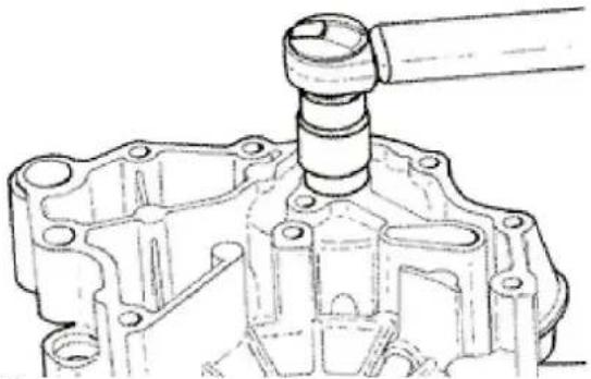
natural_image
Technical line drawing of a mechanical assembly with a cylindrical component inserted (no text or symbols)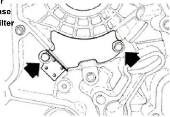
OilBpump
-Check that the pump body-shaft is free from wear.
- Check that the pump cover exhibits no wear or scratching.
- In case of non-conforming values or presence of scratches, replace the faulty parts or the assembly.
- Install the pump cover so as to allow the alignment of the holes for the crankcase fixing screws.
- Make sure that the gasket is in proper position and replace the pump on the engine crankcase.
The pump has a single installation position. Tighten the screws at the prescribed torque.
- Install the pinion with a new O-Ring.
- Install the chain.
- Install the pulley, the central screw and the spring washer. Tighten at the prescribed torque.
- Install the pump cover and lock the two screws at the prescribed torque.
N.B.
INSTALLBTHEBSPRINGBWASHERBWITHBTHEBEX-TERNALBPERIMETERBINBCONTACTBWITHBTHEBPULLEY.BCHECKBTHATBTHEBPUMPBROTATESBFREELY.
LockingBtorquesB(N\*m)
ScrewsBfixingBtheBoilBpumpBtoBtheBcrankcaseB5 ÷ B6BOilBpumpBcontrolBrimBscrewB10B ÷ B14BOil pumpBcoverBscrewsB0,7B ÷ B0,9
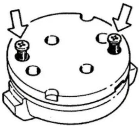
natural_image
Diagram of a mechanical component with four bolt holes and directional arrows indicating motion (no text or symbols)RemovingBtheBoilBsump
- Remove the oil loading cap, the transmission cover, the driving pulley unit with belt and the pinion as described in the Transmission chapter.
- Drain the oil from the sump as described before.
- Remove the 7 screws shown in the figure with the 2 brackets fixing the rear brake fluid piping.
- Remove the spring, the by-pass piston, the gas- ket and the centring dowels shown in the second
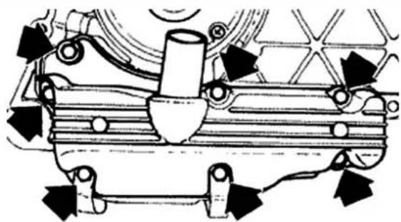
natural_image
Mechanical assembly diagram showing components like gears and springs (no text or labels)figure.
Inspecting the by-pass valve
- Check the free length of the spring.
- Check that the piston exhibits no scratches.
- Ensure that it slides freely on the crankcase and that it guarantees a good seal.
- If not, eliminate any impurities or replace defective parts.
Characteristic
Check by-pass: Standard length
54.2 mm
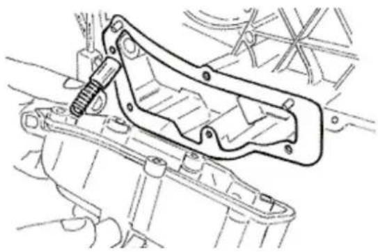
natural_image
Technical line drawing of a mechanical assembly with no visible text or symbolsRefitting the oil sump
-Replace the By-pass piston into its seat.
- Insert the adjustment spring.
- Install a new sump gasket.
- Replace the two centring dowels.
- Install the sump inserting the spring into the seat on the sump.
- Replace the screws and the rear brake support pipe brackets according to the removal reverse operations.
- Tighten the screws at the prescribed torque.
- Replace the driving pulley unit, the belt, the pinion and the transmission cover as described in chapter «Transmissions».
- As regards the checks relating to connecting rod lubrication troubles, see chapter «Crankcase and driving shaft».
Locking torques (N\*m)
Oil pan screws 10 ÷ 14
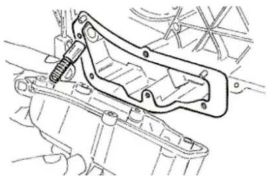
natural_image
Technical line drawing of a mechanical assembly with a threaded component (no text or symbols)SASBvalve
InspectingBtheBone-wayBvalve
- Remove the SAS valve
- Temporarily install the rubber sleeve at the outlet of the SAS valve ensuring its seal
- Connect the vacuum pump MITYVAC to the rubber sleeve as shown in the figure
- Set the pump in vacuum position (VACUUM)
- Slowly open the pump
- Check that the unidirectional valve allows the passage of the air generating a small vibration.
- Switch the pump to pressure position (PRESSURE)
- Slowly open the pump and check that there is an increase of pressure. Little leaks are normal.
In case of faults, replace
N.B.
ANBINCORRECTBOPERATIONBOFBTHEBUNIDIRECTIONALBVALVEBCANBCAUSEBTHEBOVERHEATING OFBTHEBRUBBERBSLEEVEBANDBFILTERS.
N.B.
THEBABSENCEBOFBVIBRATIONSBINDICATESBA POORBSEALING.
SpecificBtooling
020329YBPumpBMITYVAC
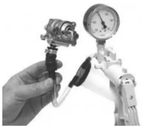
natural_image
Close-up of a hand holding a pressure sensor connected to a robotic arm with a pressure gauge (no visible text or symbols)InspectingBtheBcut-off
- Remove the SAS valve
- Connect the MITYVAC pump in vacuum position
(VACUUM) to the CUT - OFF valve vacuum inlet - Apply a vacuum of over 0.5 BAR
- Check that this value is maintained over time
- If the value is not maintained, proceed to re-
place
- Using a «T» branch and rubber hoses, implement a parallel connection between the rubber sleeve and the vacuum inlet of the CUT - OFF valve
- Connect the branch to the MITYVAC pump
- Set the pump in vacuum position (VACUUM)
- Using pliers with flat and long tips, temporarily clamp the rubber hose in the proximity of the valve
- Command the pump to create a vacuum of over 0.5 BAR
- Release the hose and check the vacuum behaviour
- In normal operating conditions, the vacuum undergoes a drop and then settles. Then there occurs a gradual and slow depression up to the value of about 0.4 BAR. At this point, the valve opens and vacuum suddenly resets.
A seal failure or opening at different vacuum values are abnormal. Proceed to the replacement.
N.B.
BESIDESBIMPAIRINGBTHEBFUNCTIONALITYBOFBTHE CUTB-BOFF,BANBINCORRECTBSEALBOFBTHEBCUTB-OFFBVALVEBMEMBRANEBAFFECTSBTHEBIDLEBOPERATION.
N.B.
ABSEALBFAILUREBOFBTHEBCUTB-BOFFBVALVE CAUSESBEXHAUSTBNOISEB(EXPLOSIONSBINBTHE SILENCER).BABWRONGBCALIBRATIONBOFBTHEBCUT -BOFFBVALVEBCANBIMPAIRBTHEBCORRECTBFUNCTIONALITYBOFBTHEBCATALYTICBCONVERTER.
SpecificBtooling
020329YBPumpBMITYVAC
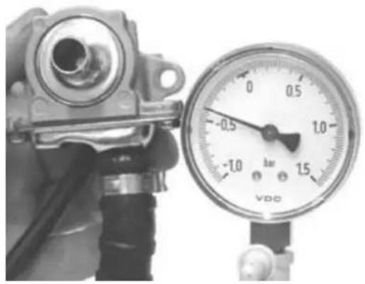
natural_image
Close-up of a mechanical pressure gauge and connector (no visible text or symbols)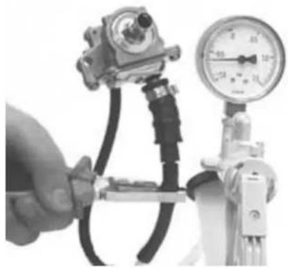
natural_image
Close-up of a hand adjusting a pressure regulator with hoses and gauges (no visible text or symbols)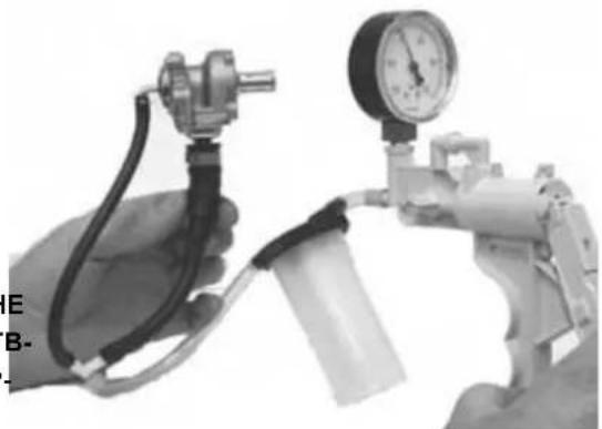
natural_image
Close-up of a hand holding a pressure regulator with a gas cylinder and tubing, no visible text or symbols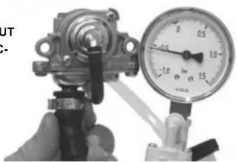
natural_image
Close-up of a hand holding a mechanical valve with a pressure gauge (no visible text or symbols)FuelBsupply
- To clean the filtering element, proceed as follows: remove the 4 cover fixing screws of the filter cover indicated in the figure; remove the cover and extract the paper filtering element, clean with compressed air and replace.
- Check the proper position of the filtering mass.
- Check that the air passage sections are free from deformations or breakage.
- Check the proper seal of the cover filter box coupling.
N.B.
FAILUREBTOBOBSERVEBTHESEBRECOMMENDATIONSBCANBCAUSEBWRONGBVACUUMBINTOBTHE FILTERBBOX,BWITHBCONSEQUENTBVARIATIONSBOF THEBCARBURETION.
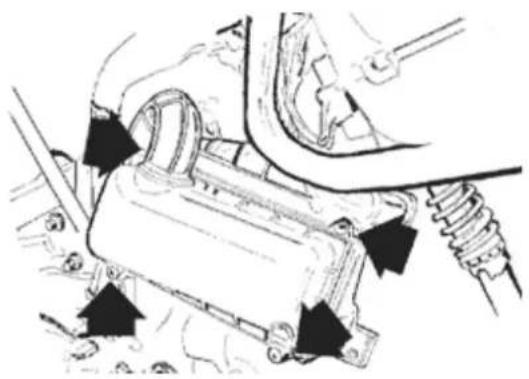
natural_image
Mechanical assembly diagram showing a component being inserted into a housing (no text or labels visible)RemovingBtheBcarburettor
Kehin
- To disconnect the carburettor from the engine, it is necessary to move the air filter and remove the gas control transmission, the automatic starter connection, the clamps fixing the carburettor to the filter box and to the intake manifold, the pipe feeding air to the membrane, and the intake union.
- Extract the carburettor and turn it to remove the screw with the water union and relevant pipes.
N.B.
THISBOPERATIONBISBREQUIREDBTOBPREVENT EMPTYINGBTHEBCOOLINGBSYSTEM.
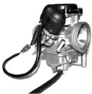
natural_image
Mechanical component with hoses and a central cylindrical body (no visible text or symbols)Remove the guard, the bracket and the starter by releasing the screw shown in the figure.
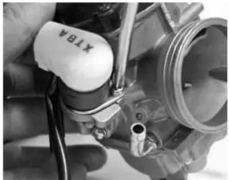
natural_image
Close-up of a mechanical component with a white cap labeled 'XTRA' and a metallic tool inserted, no visible text or symbols beyond the label.Remove the 2 screws and the starter support with the gasket.
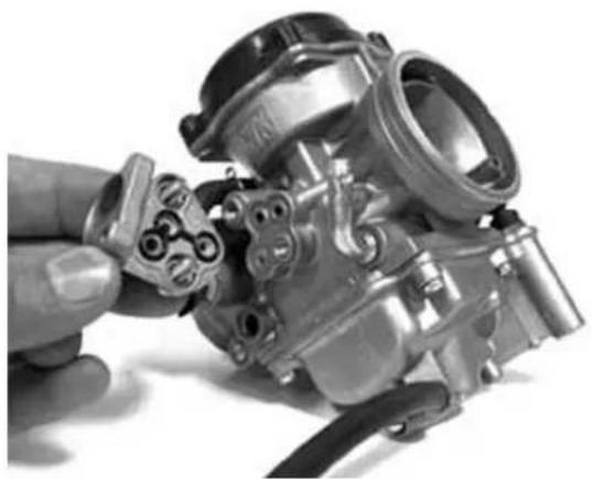
natural_image
Close-up of a hand holding a metallic mechanical component, showing internal parts and a cable (no visible text or symbols)Remove the clamp and the cap with the membrane chamber aeration filter.
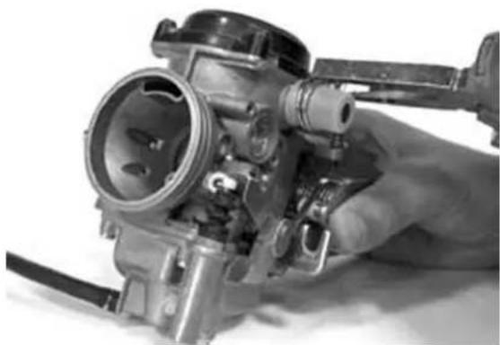
natural_image
Close-up of a hand holding a mechanical carburetor component (no visible text or symbols)Remove the 4 fixing screws shown in the figure and the vacuum chamber cover.
WARNING
DURINGBTHEBCOVERBREMOVAL,BBEBCAREFULBTO THEBSUDDENBPROJECTIONBOFBTHEBSPRING.
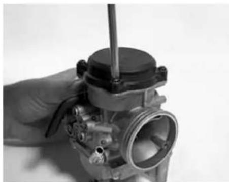
natural_image
Close-up of a hand holding a mechanical component with a screw and shaft (no visible text or symbols)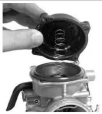
natural_image
Close-up of a hand holding a mechanical component with a spring inside, partially assembled (no visible text or symbols)Remove the vacuum valve with the membrane.
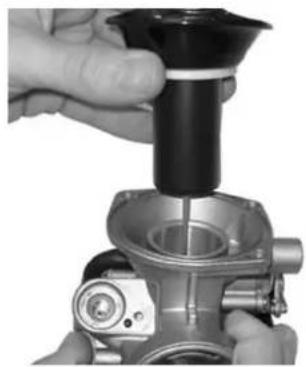
natural_image
Close-up of hands assembling a mechanical component with a cylindrical part inserted (no visible text or symbols)Loosen the coupling by 1/8 turn and remove it, remove the spring and the vacuum valve pin.
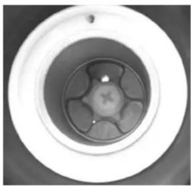
natural_image
Top-down view of a white circular mechanical component with a central hub and six radial slots (no text or symbols visible)Remove the 4 screws shown in the figure.
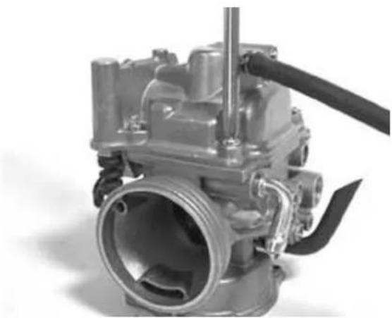
natural_image
Close-up of a mechanical engine component with hoses and shaft (no visible text or symbols)Remove the basin with the pickup pump, control
and gasket.
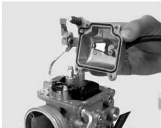
natural_image
Close-up of a hand holding a mechanical component with visible internal structure (no text or symbols)- Remove the sealing gasket.
- Remove the pickup pump intake and delivery valves from the basin.
N.B.
BEBVERYBCAREFULBSINCEBVALVESBCONSISTBOF NOZZLE,BSPRINGBANDBBALL
N.B.
DOBNOTBREMOVEBTHEBPICKUPBPUMPPISTONBAND RELEVANTBCONTROL.
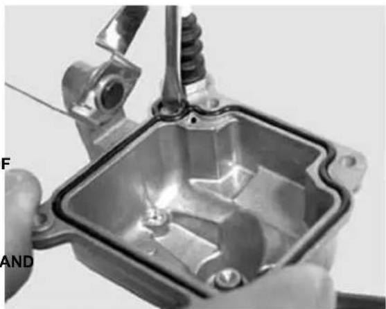
natural_image
Close-up of hands holding a metallic mechanical component with visible internal structure (no text or symbols)- Suitably support the carburettor and remove the float pin by a hammer from the gas control side.
- Remove the float and the pin.
- Remove the maximum nozzle.
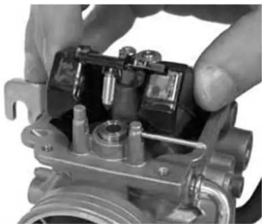
natural_image
Close-up of hands assembling a mechanical component with no visible text or symbolsRemove the maximum nozzle.
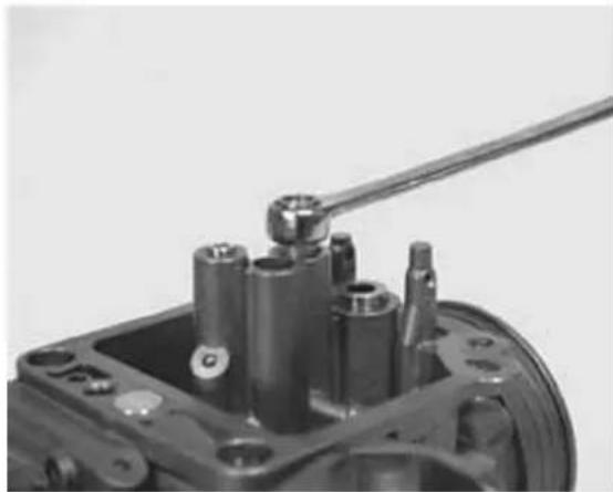
natural_image
Close-up of a mechanical switch component with cylindrical parts and mounting holes (no visible text or symbols)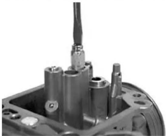
natural_image
Close-up of a mechanical component with metallic parts and a protruding shaft (no visible text or symbols)Remove the emulsifier.
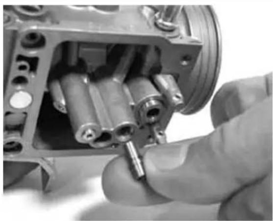
natural_image
Close-up of a hand inserting cylindrical components into a mechanical housing (no visible text or symbols)Remove the spray nozzle.
N.B.
THISBOPERATIONBISBREQUIREDBTOBPREVENT LOSINGBTHEBSPRAYBNOZZLEBDURINGBTHEBCARBURETTORBCLEANINGBOPERATIONS.BIFBTHE SPRAYBNOZZLEBISBFORCEDBINTOBITSBSEAT,BDO NOTBREMOVEBITBTOBPREVENTBDAMAGINGBIT.
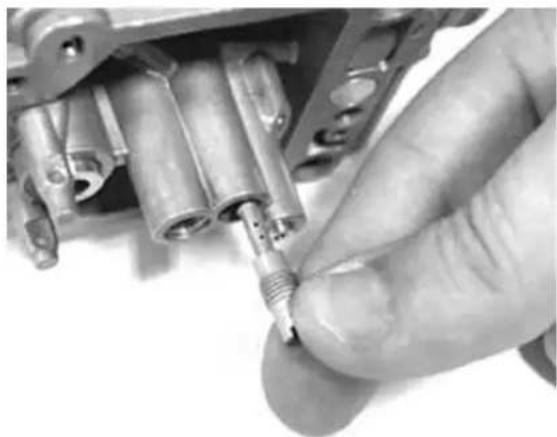
natural_image
Close-up of a hand inserting a small component into a mechanical housing (no visible text or symbols)Remove the minimum nozzle.
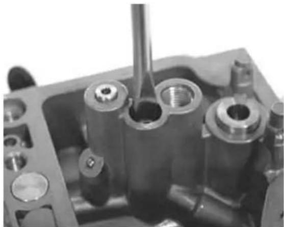
natural_image
Close-up of a mechanical component with cylindrical and threaded parts, no visible text or symbolsRemove the minimum flow adjustment screw and the spring.
CAUTION
DOBNOTBREMOVEBTHEBCOMPONENTSBFIXEDBINTO THEBCARBURETTORBBODY,BSUCHBAS:BFUEL FEEDINGBDUCT,BPINBSEAT,BSTARTERBNOZZLE, PICKUPBNOZZLEBANDBPITBCAP,BMINIMUMBAND MAXIMUMBAIRBCALIBRATOR,BTHROTTLEBVALVE CONTROLBSHAFT.BDOBNOTBREMOVEBTHEBSCREWS FIXINGBTHEBTHROTTLEBTOBTHEBSHAFT.BTHEBFIX- INGBSCREWSBAREBCAULKEDBAFTERBASSEMBLY ANDBTHEIRBREMOVALBDAMAGESBTHEBSHAFT.
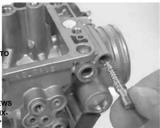
natural_image
Close-up of a mechanical component being adjusted with a screwdriver (no visible text or symbols)Walbro
- To disconnect the carburettor from the engine, it is necessary to move the air filter and remove the gas control transmission, the automatic starter
connection, the clamps fixing the carburettor to the filter box and to the intake manifold, the pipe feeding air to the membrane, and the intake union.
- Extract the carburettor and turn it to remove the screw with the water union and relevant pipes.
N.B.
THISBOPERATIONBISBREQUIREDBTOBPREVENT LOSINGBTHEBSPRAYBNOZZLEBDURINGBTHEBCAR BURETTORBCLEANINGBOPERATIONS.BIFBTHE SPRAYBNOZZLEBISBFORCEDBINTOBITSBSEAT,BDO NOTBREMOVEBITBTOBPREVENTBDAMAGINGBIT.
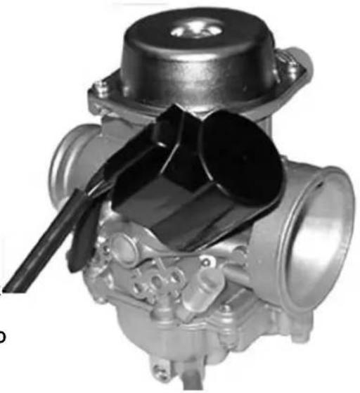
natural_image
Close-up of a mechanical component with metallic parts and a black plastic cover (no visible text or symbols)Remove the guard, the bracket and the starter by releasing the screw shown in the figure.
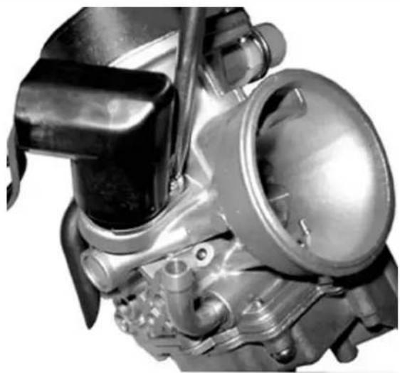
natural_image
Close-up of a mechanical engine component with visible gears and shafts (no text or symbols)Remove the clamp and the cap with the membrane chamber aeration filter.
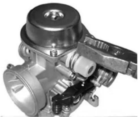
natural_image
Close-up of a mechanical valve assembly (no visible text or symbols)Remove the 4 fixing screws shown in the figure and the vacuum chamber cover.
N.B.
DURINGBTHEBCOVERBREMOVAL,BBEBCAREFULBTO THEBSUDDENBPROJECTIONBOFBTHEBSPRING.
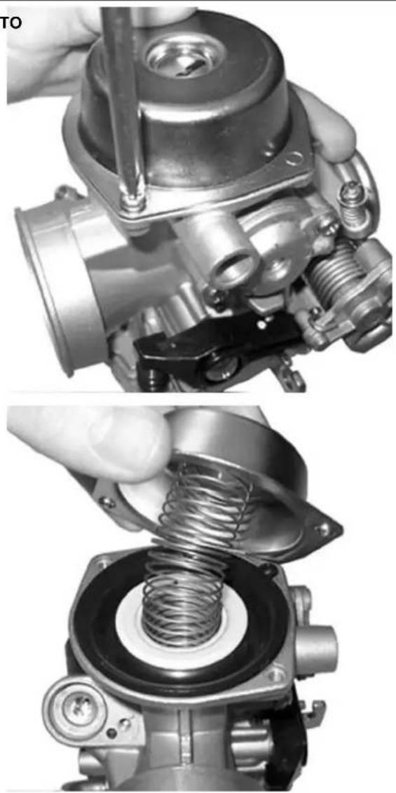
natural_image
Two-panel black-and-white photo showing a mechanical assembly: top panel shows a hand holding a tool, bottom panel shows a spring being inserted (no text or symbols visible)Remove the vacuum valve with the membrane.
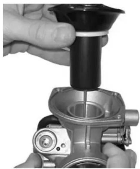
natural_image
Close-up of a hand using a mechanical tool to press or install a cylindrical component (no visible text or symbols)Loosen the coupling by 1/8 turn and remove it, remove the spring and the vacuum valve pin.
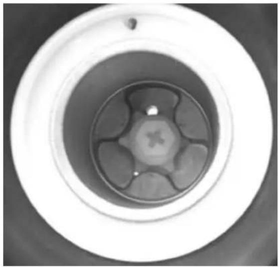
natural_image
Top-down view of a circular mechanical component with internal cross-shaped features (no text or symbols visible)Remove the 4 screws shown in the figure.
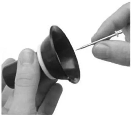
natural_image
Close-up of hands using a screwdriver to adjust a small black object (no text or symbols visible)Remove the basin with the pickup pump, control and gasket.
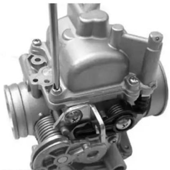
natural_image
Close-up of a mechanical engine component with visible springs and housing (no text or symbols)Remove the pickup pump with ring nut, the cas-
ing, the O-Ring and the spring from the basin as shown in the figure.
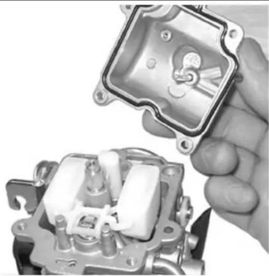
natural_image
Close-up of a hand holding an open electrical switch component (no visible text or symbols)- Suitably support the carburettor and remove the float pin by a hammer from the gas control side.
- Remove the float and the pin.
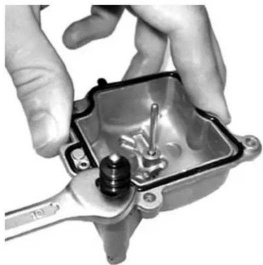
natural_image
Close-up of hands assembling a mechanical component with a tool (no visible text or symbols)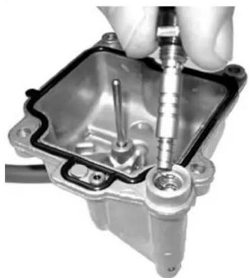
natural_image
Close-up of a hand using a screwdriver to adjust or install a mechanical component inside a square housing (no visible text or symbols)Remove the cap conveying the fuel to the starter nozzle as shown in the figure.
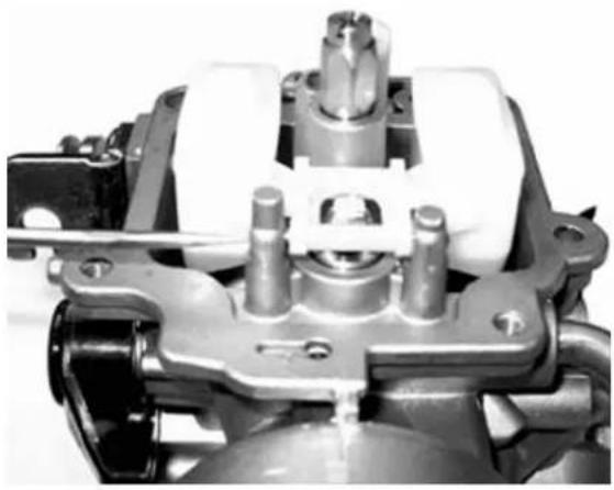
natural_image
Close-up of a mechanical assembly with gears and housing (no visible text or symbols)- Remove the maximum nozzle.
- Remove the emulsifier.
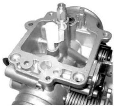
natural_image
Close-up of a mechanical assembly showing internal components and gears (no visible text or symbols)Remove the spray nozzle.
N.B.
THISBOPERATIONBISBREQUIREDBTOBPREVENT LOSINGBTHEBSPRAYBNOZZLEBDURINGBTHEBCARBURETTORBCLEANINGBOPERATIONS.BIFBTHE SPRAYBNOZZLEBISBFORCEDBINTOBITSBSEAT,BDO NOTBREMOVEBITBTOBPREVENTBDAMAGINGBIT.
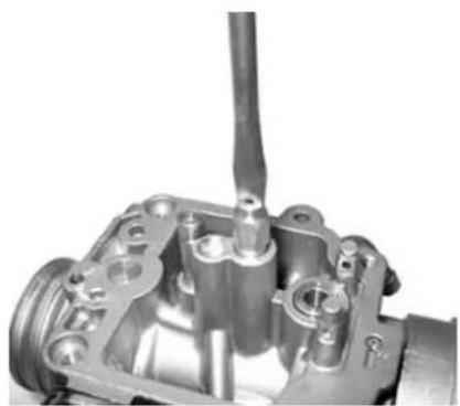
natural_image
Close-up mechanical component showing internal parts and a rod (no visible text or symbols)Remove the minimum nozzle.
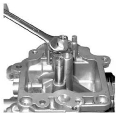
natural_image
Close-up of a mechanical component with no visible text or symbols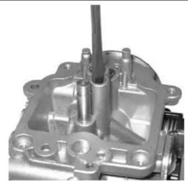
natural_image
Close-up of a metallic mechanical component with internal cavities and mounting holes (no visible text or symbols)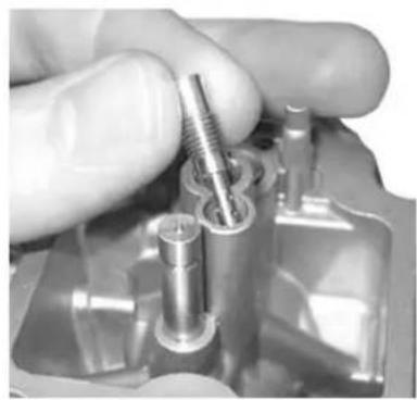
natural_image
Close-up of a hand holding a metal screw component in a mechanical housing (no visible text or symbols)- Remove the minimum flow screw with the O-Ring, washer and spring.
- Remove the 2 fixing screws, the cover, the spring and the cut-off device membrane.
CAUTION
DOBNOTBREMOVEBTHEBCOMPONENTSBFIXEDBINTO THEBCARBURETTORBBODY,BSUCHBAS:BFUEL FEEDINGBDUCT,BPINBSEAT,BSTARTERBNOZZLE, PICKUPBNOZZLEBANDBPITBCAP,BMINIMUMBAND MAXIMUMBAIRBCALIBRATOR,BTHROTTLEBVALVE CONTROLBSHAFT.BDOBNOTBREMOVEBTHEBSCREWS FIXINGBTHEBTHROTTLEBTOBTHEBSHAFT.BTHEBFIX- INGBSCREWSBAREBCAULKEDBAFTERBASSEMBLY ANDBTHEIRBREMOVALBDAMAGESBTHEBSHAFT.
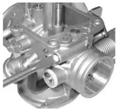
natural_image
Close-up of a metallic mechanical component with threaded shaft and internal cavities (no visible text or symbols)RefittingBtheBcarburettor
Kehin
- Before proceeding to reassembly, carefully clean the carburettor body using fuel and compressed air.
- Be especially careful to the fuel inlet duct and the pin seat.
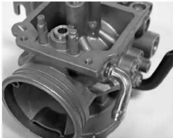
natural_image
Close-up of a mechanical component with visible gears and shafts (no text or symbols)- For the maximum circuit, check the air calibration shown in the figure.
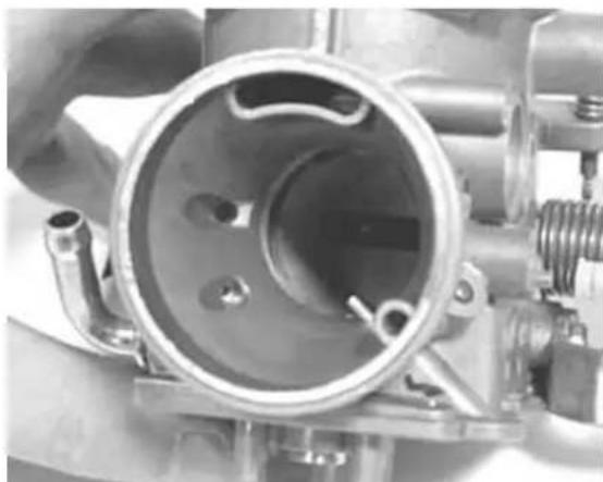
natural_image
Close-up of a mechanical component with internal cavities and bolts (no visible text or symbols)- For the minimum circuit, check the correct cleaning of the following points: air calibration, outlet section controlled by the flow screw, progression holes close to the throttle valve.
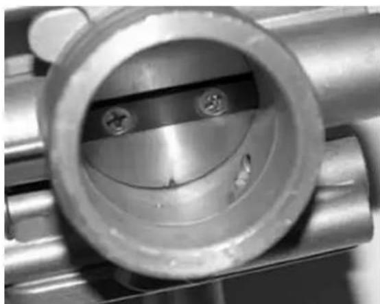
natural_image
Close-up of a metallic mechanical component with a central cylindrical feature and two bolted pins (no visible text or symbols)- For the starter circuit, carefully blow the nozzle connection duct since the nozzle support hides further internal calibrations that are not accessible.
- Carefully blow the pickup nozzle.
N.B.
ITSBOUTLETBSECTIONBISBVERYBSMALLBANDBFACESBTHEBTHROTTLEBVALVE.BABWRONGBORIENTATION OFBTHEBNOZZLEBCAUSESBABPOORBSPRAYING.
- Check that on the carburettor body there are 5 closing balls of the processing ducts.
- Check that the matching surfaces with the basin and the membrane exhibit no dents.
- Check that the vacuum valve seat is not deformed.
- Check that the throttle valve and the shaft exhibit no abnormal wear.
- Check that the pin seat exhibits no abnormal wear.
- In case of anomalies, replace the carburettor.
- Check that the pickup pump rocker return spring is not slackened.
N.B.
TOBPREVENTBDAMAGES, BDOBNOTBINSERTBMETALBOBJECTSBINTOBTHEBCALIBRATEDBSECTIONS.
- Wash and blow the minimum nozzle and then replace it.
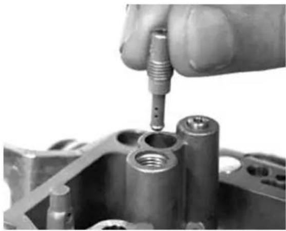
natural_image
Close-up of a hand using a screwdriver to adjust a mechanical component (no visible text or symbols)- Wash and blow the components of the maximum, emulsifier and nozzle circuit.
- Insert the spray nozzle into the carburettor body with the shorter cylindrical part facing the emulsifier.
- Install the emulsifier making sure that the spray nozzle is properly inserted, then lock it.
- Install the maximum nozzle.
- Check that the conical pin exhibits no wear on the pin sealing surface and on the return spring.
- In case of wear, replace the pin.
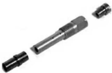
natural_image
Exploded view of a mechanical component showing internal shaft and multiple connectors (no text or symbols)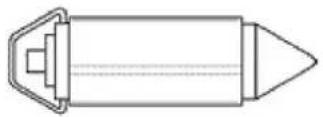
- Check that the float exhibits no wear on the pin seat or on the plate in contact with the pin, or fuel infiltrations.
- In case of anomalies, replace.
- Insert the float with the pin on the fuel feeding side.
N.B.
BEBCAREFULBTOBTHEBPROPERBINSERTIONBOFBTHEBRETURNBSPRINGBONBTHEBFLOATBPLATE.
- Remove the basin drainage screw and wash and blow the basin, be especially careful to the cleaning of the pickup pump ducts.
- Repeatedly actuate the pickup pump piston and blow with compressed air.
-
Replace the pickup pump valves in a sequence: INTAKE VALVE (A)
-
Spring
- Sphere
- Nozzle
DELIVERY VALVE (M)
- Spring
- Nozzle
- Sphere
N.B.
THEBDELIVERYBVALVEBNOZZLEBISBPROVIDED WITHBABMILLING.
- Check the screw seal by pouring a small amount of fuel into the basin.
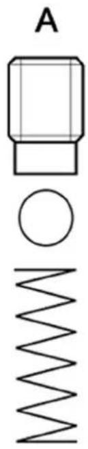
natural_image
Pure electrical circuit lines without any symbols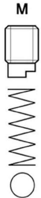
- Install a new gasket on the basin.
- Install the basin on the carburettor body and tighten the 4 screws.
- Check that the control roller is free to rotate into its seat.
N.B.
CHECKBTHEBPROPERBINSERTIONBOFBTHEBGASKET.
N.B.
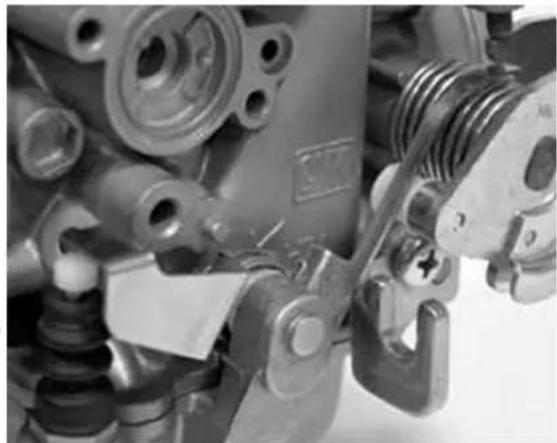
natural_image
Close-up of mechanical components including springs, bolts, and a spring (no visible text or symbols)AVOIDBANYBDEFORMATIONBOFBTHEBPICKUPBPUMP CONTROLBROCKER.
- Wash and blow the flow screw.
- Check that the screw is free from deformation and/or oxidation.
- Assemble the spring on the screw.
- Tighten the flow screw on the carburettor body.
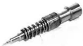
natural_image
Close-up of a mechanical screw or drill bit with threaded shaft and flanged end (no visible text or symbols)- The final position of the screw must be defined by the exhaust gas analysis.
- Prepare the carburettor for adjustment with the screw loosened by 2 turns from the closed position.
Walbro
- Before proceeding to reassembly, carefully clean the carburettor body using fuel and compressed air.
- Be especially careful to the fuel inlet duct and the pin seat.
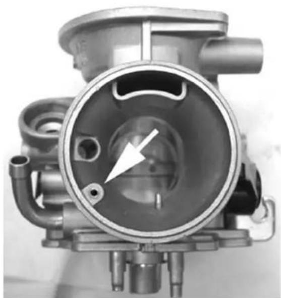
natural_image
Close-up of a mechanical component with internal cavities and a white arrow indicating a specific feature (no text or symbols visible)- For the maximum circuit, check the air calibration shown in the figure.
- Carefully clean the air holes shown in the figure.
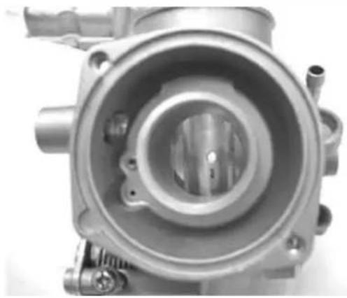
natural_image
Close-up of a mechanical component with central bore and multiple ports (no visible text or symbols)- For the minimum circuit, check the correct cleaning of the following points: air calibration, outlet section controlled by the flow screw, progression holes close to the throttle valve.
N.B.
THE MINIMUM AIR IS CONTROLLED BY TWO CALIBRATIONS. THAT OF THE CUT-OFF IS DIRECTLY OBTAINEDBINBTHEBCARBURETTORBBODY.
- For the starter circuit, carefully blow the nozzle connection duct since the nozzle support hides further internal calibrations that are not accessible.
- Carefully blow the pickup nozzle.
N.B.
ITSBOUTLETBSECTIONBISBVERYBSMALLBAND FACESBTHEBTHROTTLEBVALVE.BABWRONGBORI- ENTATIONBOFBTHEBNOZZLEBCAUSESBABPOOR SPRAYING.
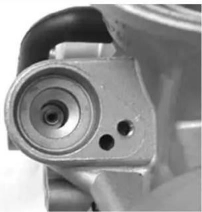
natural_image
Close-up of a mechanical component with concentric rings and two small holes (no visible text or symbols)- Check that on the carburettor body there are 5 closing balls of the processing ducts.
- Check that the matching surfaces with the basin and the membrane exhibit no dents.
- Check that the vacuum valve seat is not deformed.
- Check that the throttle valve and the shaft exhibit no abnormal wear.
- Check that the pin seat exhibits no abnormal wear.
- In case of anomalies, replace the carburettor.
N.B.
TOBPREVENTBDAMAGES, BDOBNOTBINSETBMETALBOBJECTSBINTOBTHEBCALIBRATEDBSECTIONS.
- Wash and blow the minimum nozzle and then replace it.
- Wash and blow the components of the maximum, emulsifier and nozzle circuit. - Insert the spray nozzle into the carburettor body with the shorter cylindrical part facing the emulsifier.
- Install the emulsifier making sure that the spray nozzle is properly inserted, then lock it.
- Install the maximum nozzle.
- Check that the conical pin exhibits no wear on the pin sealing surface and on the return spring.
- In case of wear, replace the pin.
- Check that the float exhibits no wear on the pin seat or on the plate in contact with the pin, or fuel infiltrations.
- In case of anomalies, replace.
- Install the float with the pin inserting the pin on the fuel feeding side.
N.B.
BEBCAREFULBTOBTHEBPROPERBINSERTIONBOFBTHEBRETURNBSPRINGBONBTHEBFLOATBPLATE.
LevelBcheck
Kehin
- Place the carburettor tilted as shown in the figure.
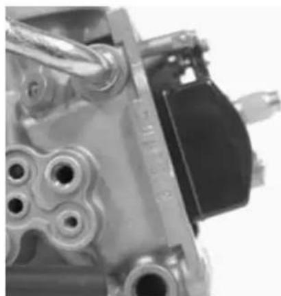
natural_image
Close-up of mechanical components including gears and a black component (no visible text or symbols)- Check that the reference on the float is parallel to the basin matching surface.
- If the position is different, change the orientation of the metal pin control plate to obtain the position described above.
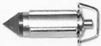
natural_image
Close-up of a metallic cylindrical object with a pointed tip and handle (no visible text or symbols)Walbro
- Check that the float matching surface is parallel to the basin surface with carburettor in upturned position.
- If the position is different, change the orientation of the metal pin control plate to obtain the position described above.
- When deforming the plate, check that it remains parallel to the floating pin.
N.B.
WITHBTHEBCARBURETTORBINBUPTURNEDBPOSITION,BTHEBFLOATBWEIGHTBMUSTBNOTBOVERCOMEBTHTHRUSTBOFBTHEBCONICALBPINBSPRING.BIFBNOTBSO,BCHECKBTHATBTHEBFLOATBISBNOTBBURDENEDBWITINFILTRATIONSBOFBFUEL,BANDBREPLACEBTHEBFLOATBORBTHEBCONICALBPIN,BIFBREQUIRED.
- Wash and carefully blow the fuel conveying cap and insert it on the starter nozzle.
N.B.
FAILUREBTOBINSTALLBTHISBPARTBCAUSESBA WORSEBCOLDBSTARTBCHARACTERISTIC,BSINCE THEBSTARTERBNOZZLEBWITHDRAWSBOLDBFUEL FROMBTHEBBASINBBOTTOM.
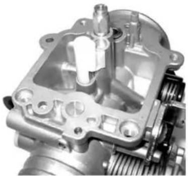
natural_image
Close-up of a mechanical assembly showing internal gears and housing (no visible text or symbols)- Remove the basin drainage screw and wash and blow the basin, be especially careful to the cleaning of the pickup pump intake and delivery valve.
- Since the valves are unidirectional, carefully blow with compressed air in the intake valve from the basin internal side and into the pump piston seat for the delivery valve.
- Check that the pickup pump piston and relevant seat into the basin are free from wear.
- In case of wear, replace the defective parts.
- Check that the pickup pump piston contrast spring is not worn.
- Install a new O-Ring and a new bellows gasket, replace the piston unit on the basin.
- Install a new O-Ring on the basin drainage screw and tighten the screw.
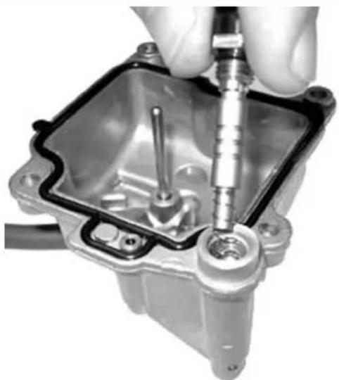
natural_image
Close-up of a hand using a screwdriver to adjust or install a mechanical component (no visible text or symbols)- Check the screw seal by pouring a small amount of fuel into the basin.
- Install a new gasket on the basin.
- Install the basin on the carburettor body and tighten the 4 screws.
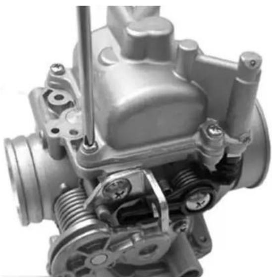
natural_image
Close-up of a mechanical engine component with visible gears and housing (no text or symbols)- Wash and blow the flow screw, install a new O-Ring.
- Pre-assemble the components on the screw in the following order: spring, washer, O-Ring.
- Tighten the flow screw on the carburettor body.
- The final position of the screw must be defined by the exhaust gas analysis.
- Prepare the carburettor for adjustment with the screw loosened by 3 turns from the closed position.
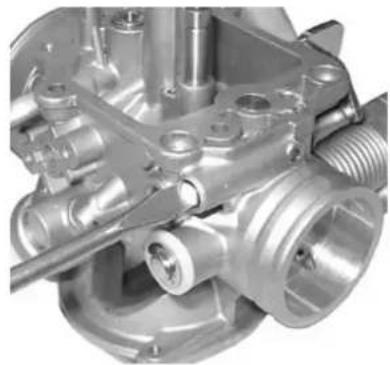
natural_image
Close-up of a metallic mechanical component with no visible text or symbols- Check that the pickup pump control rocker is free from abnormal wear.
- Check that the rocker travel end screw protrudes by 3.2 mm.
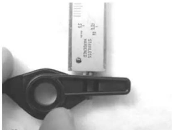
natural_image
Close-up of a hand holding a black plastic clamp next to a metallic cylindrical device (no visible text or symbols)- Check that the rocker return spring is not slackened.
- Pre-assemble the spring and the rocker as shown in the figure.
- Install the rocker on the carburettor keeping the throttle valve open.
- Tighten the rocker fixing screw.
- Make sure that the gear works properly.
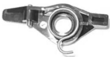
natural_image
Mechanical component with coiled spring and mounting bracket (no visible text or symbols)InspectingBtheBvalveBandBneedle
Kehin
- Check that the vacuum valve conical pin is free from wear.
- Check that the vacuum valve exhibits no scratches on the outside surfaces.
- Check that the vacuum feeding hole is not clogged.
- Check that the membrane is not broken or hardened, if not so, replace the entire valve.
- Insert the conical pin into the vacuum valve seat.
- Replace the vacuum gas valve on the carburet-tor body being careful to insert the pin into the spray nozzle.
N.B.
THEBVALVEBCANBBEBINSERTEDBINBABSINGLEBPOSITIONBONLY.
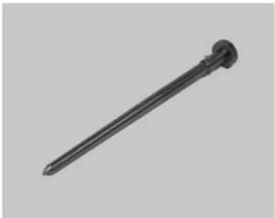
natural_image
Black nail with a pointed tip and circular head (no text or symbols visible)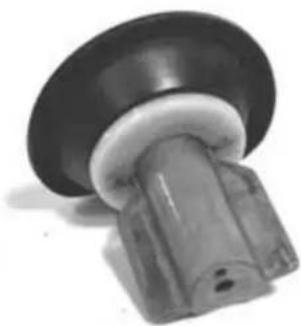
natural_image
Close-up of a black and white mechanical component with a cylindrical shaft (no visible text or symbols)- Replace the spring with the pin lock.
- Replace the vacuum chamber cover checking the proper positioning of the spring into the hous-
ing on the cover.
- Tighten the screws at the prescribed torque.
Locking torques (N\*m)
Vacuum chamber cover screws: XX N m
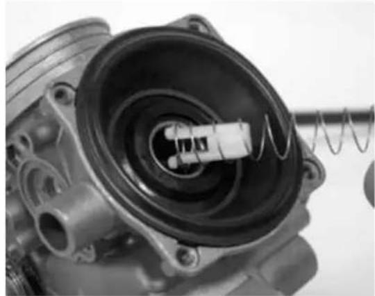
natural_image
Close-up of a mechanical component with internal components and a spring, no visible text or symbols- Wash and blow the ambient pressure inlet filter sponge.
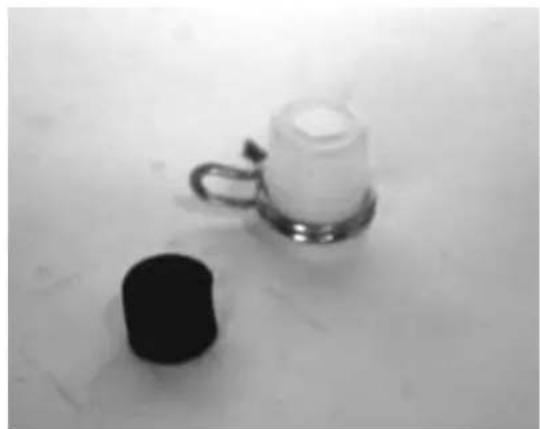
natural_image
Black and white photo of a small black cylindrical object and a small white container on a metal stand (no text or symbols visible)- Replace the filter and its clamp.
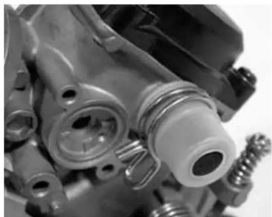
natural_image
Close-up of mechanical components including a valve, screw, and housing (no visible text or symbols)- Wash and blow the starter support.
- Install a new gasket on the carburettor body and tighten the 2 fixing screws.
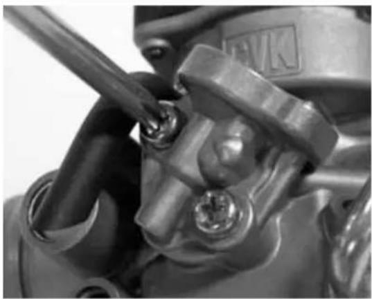
natural_image
Close-up of a mechanical component with bolts and a wrench, no visible text or symbolsWalbro
- Check that the pin exhibits no wear and that the lock is in the third notch out of 3.
- Check that the vacuum valve exhibits no scratches on the outside diameter.
- Check that the 2 vacuum feeding hole are not clogged.
N.B.

THEB2BHOLESBHAVEBABDIFFERENTBDIAMETER.
- Check that the membrane is not broken or hardened, if not so, replace it.
- Replace the conical pin on the vacuum valve.
- Check the correct positioning of the spring on the pin and the snapping into the relevant seat.
- Install the coupling by turning it by 1/8 turn.
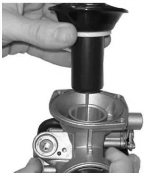
natural_image
Close-up of hands assembling a mechanical component with a black cylindrical part inserted (no visible text or symbols)- Replace the vacuum gas valve on the carburet-tor body being careful to insert the pin into the spray nozzle.
- Time the vacuum valve rotation inserting the membrane tail into the relevant seat.
When the membrane is properly assembled to the valve, the main vacuum feeding hole is in axis with the diffuser, on the throttle valve side.
- Replace the spring on the valve.
- Replace the vacuum chamber cover matching the reference with the membrane orientation reference.
- Tighten the screws at the prescribed torque.
- Check the cut-off valve functionality. Check that the membrane is not broken or hardened. Check the free length of the spring.
Characteristic
Walbro: Standard length
24 mm
- Replace the membrane with the metal pin positioned on the valve.
- Replace the spring and the cover. The cover must have the vacuum inlet facing upwards
Inspecting the automatic choke device
- Check that the automatic starter piston exhibits no scratches or oxidation.
- Check that the piston slides freely into the seat.
- Check that the piston sealing gasket exhibits no deformations.
- The starter must be more or less inserted according to the ambient temperature.
- Measure the projection of the piston as shown in the figure, and check the corresponding value.
- Ensure that the starter settles at ambient temperature.
- Install the starter on the carburettor checking the proper positioning of the O-Ring, insert the plate with the knurling resting against the starter, tight-
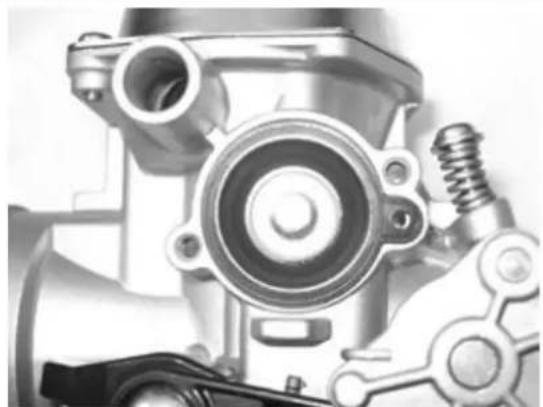
natural_image
Close-up of a mechanical component with gears and springs (no visible text or symbols)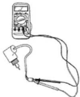
natural_image
Line drawing of a multimeter connected to a probe and cable (no text or symbols)en the 2 fixing screws.
- Orientate the starter as in the figure.
- Install the safety casing.
- The actual heating time depends on the ambient temperature.
- If you detect projections, resistance or times differing from those prescribed, replace the starter.
- The starter should gradually disconnect by the electric heating.
- Check the starter resistance when settled at ambient temperature.
- Using a 12V battery, power the automatic starter and check that the pèiston reaches the maximum protrusion.
Characteristic
Automatic starter check: projection value
12.5 ÷ 13 mm at about 20°C
Automatic starter check: Maximum projection
18,5 ÷ 19 mm
Automatic starter check: Max time
5 min
Electric characteristic
Automatic starter check: Resistance
about 30
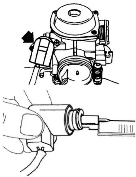
natural_image
Technical illustration showing a mechanical assembly and a hand holding a tool, both without any text or symbols.Kehin
- Check that the automatic starter piston exhibits no scratches or oxidation.
- Check that the piston slides freely into the seat.
- Check that the piston sealing gasket exhibits no deformations.
- The starter must be more or less inserted according to the ambient temperature.
- Measure the projection of the piston as shown in
the figure, and check the corresponding value.
- Ensure that the starter settles at ambient temperature.
- The starter should gradually disconnect by the electric heating.
- Check the starter resistance when settled at ambient temperature.
- Using a 12V battery, power the automatic starter and check that the piston reaches the maximum protrusion.
- The actual heating time depends on the ambient temperature.
- If you detect projections, resistance or times differing from those prescribed, replace the complete starter.
- Install the starter on the carburettor checking the proper positioning of the O-Ring, insert the plate with the knurling resting against the starter, tighten the fixing screw.
- Orientate the starter as in the figure.
- Install the safety casing.
N.B.
TOBPERFORMBTHISBCHECK,BBEBCAREFULBNOTBTO GENERATEBANYBSHORTBCIRCUITS.BTOBTHISBPUR- POSE,BUSEBABCABLEBWITHBSUITABLEBTERMINAL FORBCONNECTINGBTOBTHEBSTARTER.
Characteristic
AutomaticBstarterBcheckBKehinBmaxBtime
5 min
AutomaticBstarterBcheckBKehinBmaximumBprojection
XXX ÷ XXX mm
AutomaticBstarterBcheckBKehin
XX ÷ XX mm at about 20°C
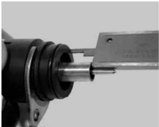
natural_image
Close-up of a mechanical assembly with a metallic shaft and threaded component (no visible text or symbols)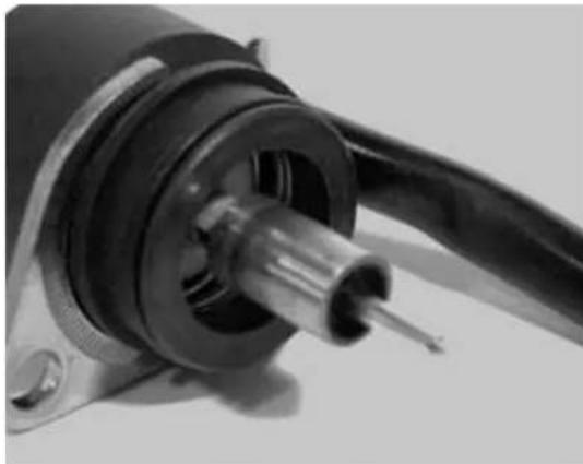
natural_image
Close-up of a mechanical component with a metallic shaft and black housing (no visible text or symbols)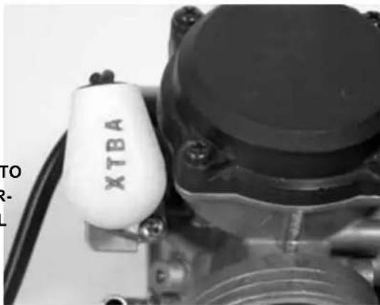
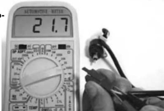
Walbro
- Check that the automatic starter piston exhibits no scratches or oxidation.
- Check that the piston slides freely into the seat.
- Check that the piston sealing gasket exhibits no deformations.
- The starter must be more or less inserted according to the ambient temperature.
- Measure the projection of the piston as shown in the figure, and check the corresponding value.
- Ensure that the starter settles at ambient temperature.
- The starter should gradually disconnect by the electric heating.
- Check the starter resistance when settled at ambient temperature (20 ÷ 25 °C).
- Using a 12V battery, power the automatic starter and check that the piston reaches the maximum protrusion.
- The actual heating time depends on the ambient temperature.
- If you detect projections, resistance or times dif- fering from those prescribed, replace the starter.
Characteristic
Automatic starter check: projection value
12.5 ÷ 13 mm at about 20°C
Automatic starter check Walbro maximum projection
18.5 ÷ 19 mm
Automatic starter check Walbro max time
5 min
Electric characteristic
Resistance Walbro
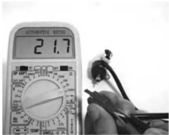
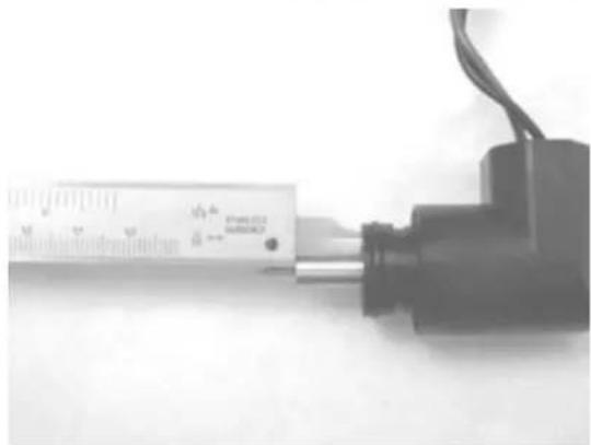
natural_image
Close-up of a small electronic device with a ruler and cable, no visible text or symbols on the device itself.about 40
Adjusting the idle
- The engine does not require frequent idle adjustments, but it very important to adjust in compliance with a few rules.
- Before adjusting the carburettor, ensure that good lubrication, valve clearance and timing are good, that the spark plug is in excellent conditions, that the air filter is clean and the exhaust system is sealed.
- Warm the engine for at least 5 minutes at 50 Km/h.
- Connect the vehicle to the exhaust gas analyser inserting the probe into the analyser in an extension pipe fitted to the silencer outlet.
- Connect the thermometer of the multimeter (020331y) to the sump, using a cap with oil load specially prepared to insert the probe.
- Start the engine and check that the oil temperature is between 70 - 80 °C.
- Using the analyser rpm counter or another one (020332y), adjust the idle screw to obtain 1,600 - 1,700 rpm
- Adjust the flow screw to obtain a carbon dioxide percentage (CO) of 3.1 - 4.5%, loosening the screw the CO value increases (rich mixture), screwing the CO value decreases (lean mixture).
- If the adjustment of the position of the flow screw increases the speed, adjust the revolutions and the flow screw to obtain steady values.
- Idle carburetion is correct when the oil temperature, rpm number and carbon dioxide percentage values are respected. The analyser provides fur-

natural_image
Close-up of a mechanical assembly with hoses and components, no visible text or symbols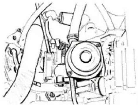
natural_image
Technical line drawing of a mechanical assembly with no visible text or symbols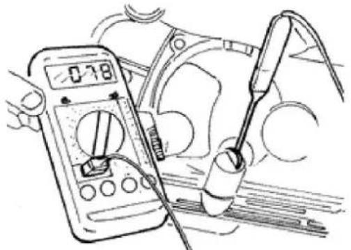
natural_image
Illustration of a multimeter measuring a car's electrical components with a tool (no text or symbols visible)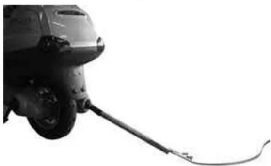
natural_image
Side view of a vehicle's wheel and cable, no visible text or symbolsther information: - carbon dioxide percentage (CO2), the percentage of carbon dioxide differs from (CO), correct values are higher than 12.5%. Non-conforming values indicate a poor seal of the exhaust gas.
- Unburnt hydrocarbons (HC) are measured in parts per million (PPM), the HC value decreases with the increase of the revolution speed, with idle engine a value of 200 ÷ 400 PPM is normal; these values are normal for engines with motor-cycle timing diaphragm. Much higher values can be caused by an engine miss due to too lean mixture (low CO), ignition failures or wrong timing or a non-òsealed exhaust valve.
- If it is difficult to adjust the CO, check:
- Carburettor cleaning
- Automatic starter efficiency
- Efficiency of the conical pin-seat
- Sump level adjustment
- Cut-off device efficiency (only 200 - 250 cc).
N.B.
THEBIGNITIONBSYSTEMBISBOFBTHEBSPARKBTYPE ANDBHASBABVERYBHIGHBPOWER.BUSINGBWRONG RPMBCOUNTERSBMAYBCAUSEBDIFFICULTIESBIN THEBREADING.BTHEBRPMBCOUNTERBMATCHINGBIS CORRECTBWHENBITBCANBREADBHIGHBSPEEDS TOO,BSUCHBASB6,000B-B8,000BRPM.
N.B.
THEBEXTENSIONBPIPEBISBREQUIREDBTOBAVOID WITHDRAWINGBEXHAUSTBGASBFROMBTHEBAMBIENTBOXYGEN.BUSEBABGASBANALYSERBWARMEDBIN ADVANCEBANDBCAPABLEBOFBENSURINGBTHEBRESETBOFBTHEBGASBREADINGBANDBABCORRECTBGAS RATE.BFAILUREBTOBCOMPLYBWITHBTHESEBRULES MAYBGIVEBABWRONGBREADING.
Characteristic
EngineBidle:BLength
500 ÷ 600 mm
Engine idle: Pipe dimensions
∅ 40 mm
INDEX OF TOPICS
SUSPENSIONS
This section provides information on the operations that may be carried out on the suspensions.
Front
RemovingBtheBfrontBwheel
- Remove the 5 fixing screws shown in the figure.
LockingBtorquesB(N*m)
WheelBfixingBscrewsB20B÷B25
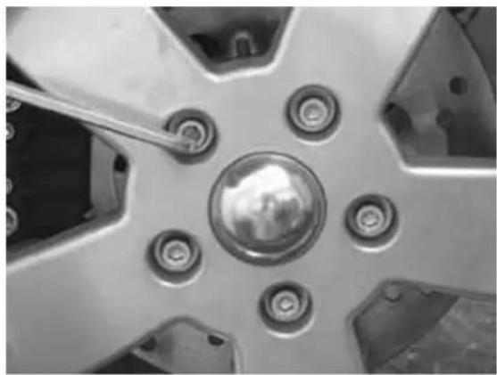
natural_image
Close-up of a car wheel rim with screw holes and a central hub (no text or symbols visible)FrontBwheelBhubBoverhaul
- Remove the ball bearing lock snap ring shown in the figure
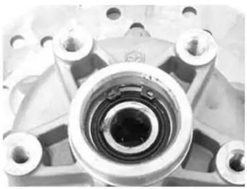
natural_image
Close-up of a mechanical bearing assembly with multiple bolts and a central bore (no visible text or symbols)Using the specific tool, remove the ball bearing.
SpecificBtooling
001467Y014B15BmmBpliers
001467Y017BBellBforBbearingsBexternalB∅B39 mm
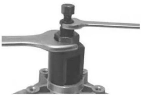
natural_image
Mechanical component with lever and base mount (no visible text or symbols)- Using a screwdriver, remove the oil guard on the roller bearing side.
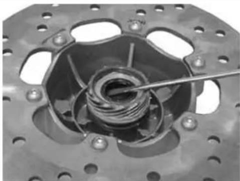
natural_image
Close-up of a mechanical clutch assembly with visible springs and bolts (no text or symbols)Using the specific tool, remove the roller bearing
SpecificBtooling
020376YBHandleBforBpunches
020456YB∅B24BmmBadapter
020363YB20mmBguide
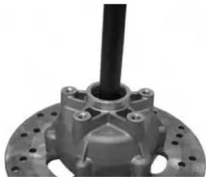
natural_image
Close-up of a mechanical component with a black shaft and bolted base (no visible text or symbols)- Using a thermal gun, warm the roller bearing seat
- Using the specific tool, insert the bearing with the screened side facing outwards and move it to travel end
- Replace the ball bearing lock snap ring
SpecificBtooling
020151YBAirBheaterB"METABOBHGB1500/2"
020376YBHandleBforBpunches
020359YB42BxB47BmmBhubBbearingBfittingBadaptor
020412YB15BmmBguide
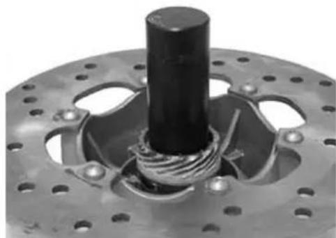
natural_image
Close-up of a mechanical component with a central cylindrical shaft and flanged base (no visible text or symbols)- Using the specific tool, insert the roller case and move it to travel end
- Replace the oil guard on the roller bearing side
- Apply grease between ball and roller bearings
SpecificBtooling
020038y Drift
Recommended products
JOTA 3 FS Speedometer transmission
Lithium soap grease NLGI 33
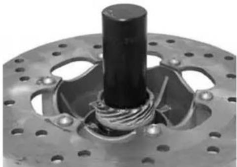
natural_image
Close-up of a mechanical component with a central cylindrical shaft and threaded base (no visible text or symbols)Refitting the front wheel
- For re-assembly, perform the operations for removal in the reverse order according to the tightening torque
Locking torques (N*m)
Wheel fixing screws 20 ÷ 25
Steering column
Overhaul
This operation should be carried out only if really needed and in any case, replacing the old parts removed with new parts.
- Remove the steering tube
- Using the specific tool, remove the top fifth wheel seat on the steering head from the bottom of the latter, as shown in the figure. Then, work from the top to remove the bottom fifth wheel seat
Specific tooling
020004Y Drift for removing thrust rings from steering head tube
- Using the specific tool, remove the fifth wheel seat and the dust guard on the steering tube as shown in the figure. Proceed by slightly hitting with a mallet.
Specific tooling
020004Y Drift for removing thrust rings from steering head tube
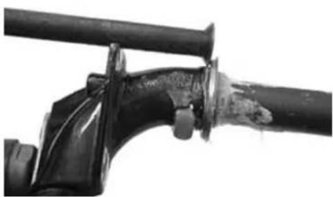
natural_image
Close-up of a damaged pipe joint with visible wear and corrosion (no text or symbols)- Using the specific tool, replace the dust guard and the fifth wheel seat on the steering tube to abutment.
Specific tooling
006029y Drift for fitting thrust ring seats on steering tube
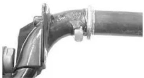
natural_image
Close-up of a pipe joint with attached metal components (no visible text or symbols)- Using the specific tool, install the fifth wheel seats on the head as shown in the figure
Specific tooling
020037y Drift
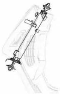
natural_image
Technical line drawing of a mechanical assembly or linkage component (no text or symbols visible)- Remove the steering tube
- Remove the shock absorber-caliper coupling bracket
- Apply the specific tool provided with part 1 and move the handle to obtain the concurrent ejection of the pin and of the Nadella opposed to the tool thrusting action.
- To eject the second Nadella, use the tool provided with part 2 in replacement of part 1, on the side opposed that shown in the figure.
Specific tooling
020021Y Front suspension overhaul tool
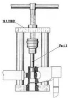
Refitting
For re-assembly, perform the operations for removal in the reverse order, applying grease on the fifth wheel seats and respecting the tightening torques.
Locking torques (N*m)
Steering wheel to the steering tube 45 ÷ 50 Nm Steering upper collar 30 ÷ 40 Steering lower collar 8 ÷ 10
Front shock absorber
Removal
- Remove the steering tube
- Remove the shock absorber bottom fixing screws
- Remove the top shock absorber attachments
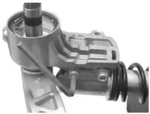
natural_image
Mechanical assembly component with gears and housing (no visible text or symbols)Refitting
- For re-assembly, perform the operations for removal in the reverse order according to the tightening torques.
Locking torques (N*m)
Shock absorber top fixing 20 - 27 Nm Shock absorber bottom fixing 20 - 30 Nm
Shock-absorber - calliper bracket
- Remove the wheel hub with the brake disc
- Remove the front shock absorber bottom fixing screws
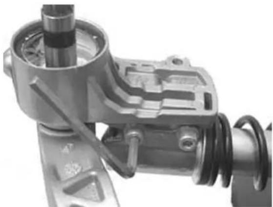
natural_image
Mechanical assembly component with gears and housing (no visible text or symbols)- Remove the bracket lock snap ring
- Extract the bracket
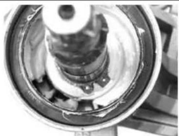
natural_image
Close-up of a mechanical gear assembly with visible teeth and central shaft (no text or symbols)- Before replacing the bracket into the wheel axle, place the o-ring as shown in the figure in order to have a proper positioning of the same after the installation of the bracket.
- Replace the washer and the snap ring
- Replace the screws fixing the shock absorber to the bracket and tighten at the prescribed torque
Locking torques (N*m)
Shock absorber bottom fixing 20 ÷ 27 Nm
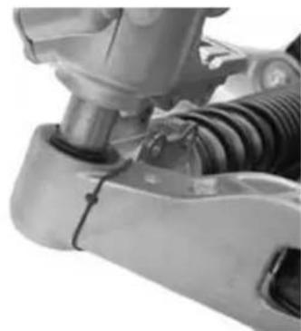
natural_image
Close-up of a mechanical assembly with no visible text or symbolsOverhaul
- The caliper - shock absorber fixing bracket is provided with two roller bearings spaced from one another as shown in the figure
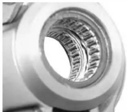
natural_image
Close-up of a mechanical bearing or gear component showing internal teeth and central bore (no text or symbols visible)- Remove the two roller bearings from the bracket using the specific tool from the shock absorber coupling side, as shown in the figure
Specific tooling
020376Y Handle for punches
020441y 26 x 28 mm adapter
020365y 22 mm guide
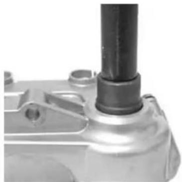
natural_image
Close-up of a mechanical component with a cylindrical shaft and flange (no visible text or symbols)- Remove the oil guard on the wheel hub side using a screwdriver as shown in the figure
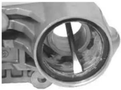
natural_image
Close-up of a mechanical component with a circular opening and internal shaft (no visible text or symbols)- Suitably support the shock absorber - brake caliper bracket
- Using the specific tool, install a new oil guard and move it to travel end
Specific tooling
020376Y Handle for punches
020360Y 52 x 55 mm adaptor
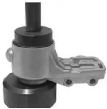
natural_image
Close-up of a mechanical assembly with a cylindrical component and a gray housing (no visible text or symbols)- Using the specific tool, install a new roller bearing on the shock absorber side and move it to travel end
Specific tooling
020036y Drift
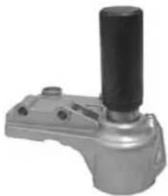
natural_image
Exterior view of a mechanical device with a cylindrical shaft and mounting base (no visible text or symbols)- Suitably support the shock absorber - brake caliper bracket
- Using the specific tool, install a new oil guard and move it to travel end
Specific tooling
020037y Drift
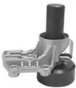
natural_image
Mechanical component with cylindrical shaft and mounting bracket (no visible text or symbols)Rear
Removing the rear wheel
- Remove the rear shock absorber - silencer support bracket
- Release the 5 screws shown in the figure to remove the rear wheel
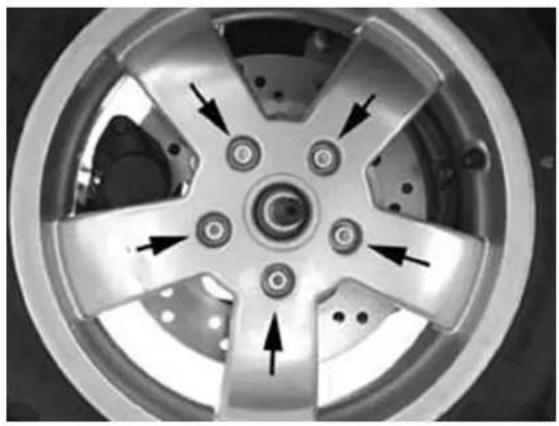
natural_image
Close-up of a car wheel rim with six spokes and mounting holes, showing directional arrows (no text or symbols)Refitting the rear wheel
For re-assembly, perform the operations for removal in the reverse order according to the prescribed torques.
Locking torques (N*m)
Wheel fixing screws: 20÷25 Nm
Swing-arm
Removal
- Rest the vehicle on the central stand;
- Remove the air cleaner box.
- Remove the screw fixing the oscillating arm to the engine as shown in the figure
- Retract the engine
- Remove the spring anchoring the oscillating arm to the chassis as shown in the figure
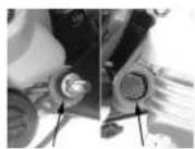
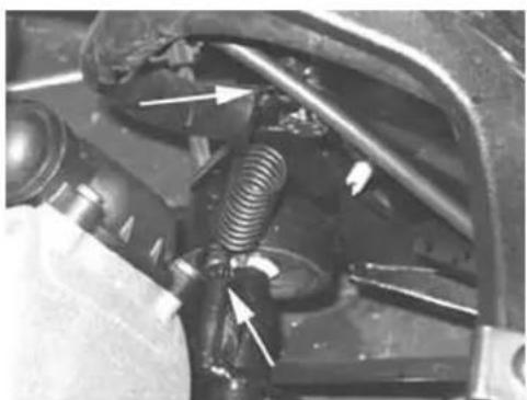
natural_image
Close-up of a mechanical assembly with springs and connectors (no visible text or symbols)- Remove the two screw fixing the pad support bracket to the chassis
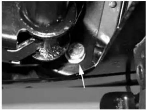
natural_image
Close-up of mechanical components with a white arrow pointing to a small component (no visible text or symbols)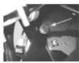
- Remove the right and left caps located under the footboard to access the pin fixing the oscillating arm to the body.
- Remove the pin. Then, remove the oscillating arm.
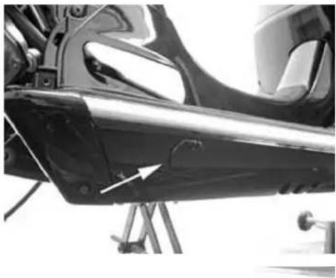
natural_image
Close-up of a black aircraft fuselage with visible structural components and an arrow pointing to a specific part (no text or symbols)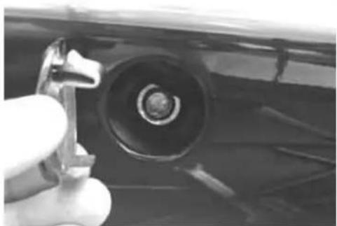
natural_image
Close-up of a hand holding a small mechanical component, partially visible against a dark vehicle (no text or symbols)- Check the entire oscillating arm unit.
- Check all components, centring bushes, rubber pads, silent block.
- Replace worn parts that cause excessive clearance on the rear suspension.
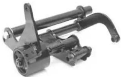
natural_image
Mechanical assembly component with articulated arms and housing (no visible text or symbols)Overhaul
- Check that the silent bloc is not broken. Replace them, if necessary
- Remove the snap ring shown in the figure
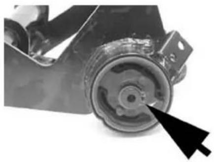
natural_image
Close-up of a mechanical component with a black arrow pointing to a circular feature (no visible text or symbols)- Remove the bracket and the silent bloc
- Remove the silent bloc ring shown in the figure
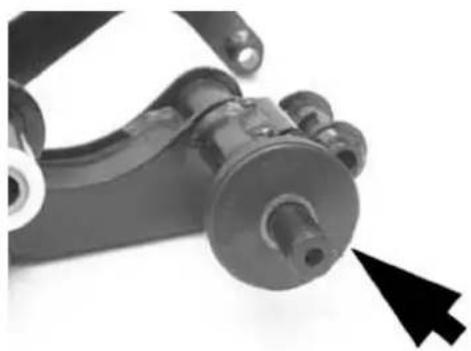
natural_image
Close-up of a mechanical linkage component with a black arrow pointing to a specific part (no text or symbols visible)- Support the bracket and the silent bloc in a vice
- Using the specific tool, extract the silent bloc from the bracket on the side corresponding to the vehicle interior. This is to ensure the tool centring on the support.
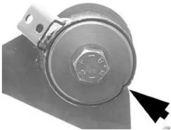
natural_image
Close-up of a metallic mechanical component with a hexagonal bolt and mounting bracket, showing a black arrow pointing to a detail (no text or symbols visible)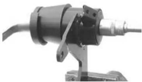
natural_image
Mechanical component with cylindrical shaft and mounting bracket (no visible text or symbols)- Install a new silent bloc ensuring the alignment
with the reference tooth.
- Fit the silent bloc by properly matching the silent bloc chamfering with that of the bracket
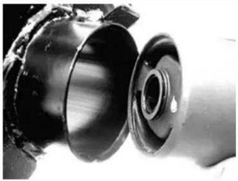
natural_image
Close-up of a mechanical component with a cylindrical shaft and flange (no visible text or symbols)- Using the specific tool, install the silent bloc as shown in the figure
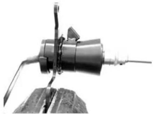
natural_image
Close-up of a mechanical device with a cylindrical component and protruding blades (no visible text or symbols)- Check that there are no dents on the joint connecting the oscillating arm on the engine side to the oscillating arm on the chassis side - Check the axial clearance between the two oscillating arms using a thickness gauge
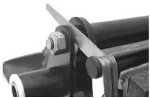
natural_image
Close-up of mechanical components with black cylindrical parts and a metallic clamp (no visible text or symbols)Characteristic
Standard clearance
0,40 ÷ 0,60 mm
Admissible limit after use
1,5 mm
- To check the clearance on the chassis side arm, prepare the fixing using the pin fixing the oscillating arm to the chassis and two adapter rings of the specific tool. Alternatively, use two washers with ∅ internal for 12 mm pins, ∅ external min. 30 mm and min. thickness 4 mm.
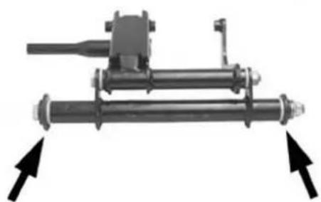
natural_image
Mechanical assembly diagram showing a shaft and housing with two directional arrows pointing to the shaft (no text or symbols present)- Check that the rotation is smooth.
- Check the axial clearance of the oscillating arm on the chassis side
Characteristic
Standard clearance
$$ 0, 4 0 \div 0, 6 0 \mathrm{mm} $$
Admissible limit after use
1,5 mm
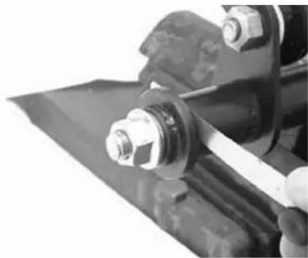
natural_image
Close-up of mechanical components with bolts and a curved rod (no visible text or symbols)- Separate the oscillating arm on the engine side from the arm on the vehicle side.
- Remove the plastic bushes and the inside spacer shown in the figure
- Using a suitable pin, remove the roller cases as shown in the figure
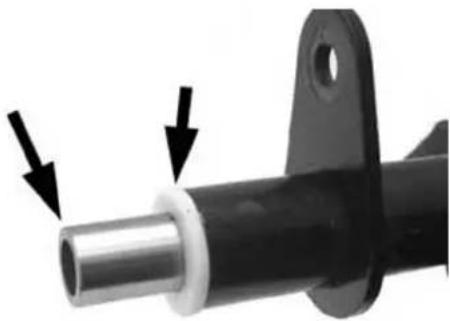
natural_image
Close-up of a mechanical component with a metallic shaft and mounting flange, marked by two arrows pointing to features (no text or symbols visible)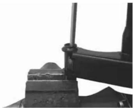
natural_image
Close-up of a mechanical clamping device with metal components and a bolt (no visible text or symbols)- Using the specific tool, fit new cases being careful to position bearings with sealing rings facing outwards
Specific tooling
020244Y Drift ∅ 15
020115Yy Drift ∅ 18
Characteristic
Engine side oscillating arm tube length:
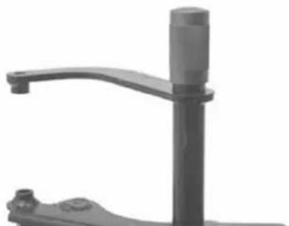
natural_image
Close-up of a mechanical lever handle and lever arm (no text or symbols visible)L 175,3 + 0,3 0
Engine side oscillating arm inside spacer length:
L 183 + 0,3 0
Engine side oscillating arm plastic bush thickness:
3,5 ± 0,05 mm
Chassis side oscillating arm plastic bush thickness:
3,5 ± 0,05 mm
Chassis side oscillating arm inside spacer length:
290 ± 0,1 L mm
Chassis side oscillating arm tube length:
L 283 ± 0,1 mm
- Lubricate with grease the roller cases and the plastic bushes
- Insert the spacers
- Assemble the two arms with the relevant bolt in the position shown in the figure
- Orientate the bolt as shown in the figure
- Place the oscillating arm on the chassis side with the most protruding part facing the silent bloc as shown in the figure
Recommended products
TUTELA ZETA 2 Grease for steering wheel bearings, pin seats and oscillating arm
Lithium soap and zinc oxide grease NLG12 for the oscillating arm
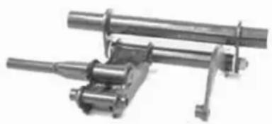
natural_image
Mechanical assembly with cylindrical components and a bracket (no visible text or symbols)Refitting
For re-assembly, perform the operations for removal in the reverse order referring to the figure below
- Lubricate the bearings and revolving parts with grease
-Complete the assembly tightening the nuts on the relevant pins at the correct tightening torques
Locking torques (N\*m)
Pin connecting the oscillating arm on the engine and vehicle side 33 ÷ 41 Nm Oscillating arm pin - Engine 64 ÷ 72 Body - oscillating arm pin 76 ÷ 83 Nm Screw fixing the silent-blockBsupportBplateBtoBtheBbodyB42B÷B52BNm
- Install the two dust guard rings «C» on the oscillating hub as shown in detail «A».
- Connect the oscillating hub to the steering tube by the guiding pin part 5.
- Apply the specific tool provided with part 3 onto the stem, and with part 4, on the tool base.
- Insert the pin, greased beforehand with grease, on the oscillating hub and move the tool handle to move part 3 in abutment on the steering tube.
- After having installed the pin, introduce the two spacers part 17 using a mallet (see next figure).
CAUTION
REASSEMBLEBWITHBNEWBROLLERBBEARINGS, PIN, BOILBSEALSBANDBDUSTBSEALS.
SpecificBtooling
020021YBFrontBsuspensionBoverhaulBtool
To assemble sealing rings, roller cases and wedging washers, proceed as follows
- Lubricate the sealing rings with mineral oil and half fill the roller cases with grease.
- Introduce the sealing ring on the pin and at the same time, the roller bushing with wedging washer.
- Remove the specific tool, then part 5 (guide) partly ejected in the previous assembly step; let part 4 on.
- On the stem, replace part 3 with part 16.
- Push the handle to push the wedging washer - sealing ring assembly to move part 16 in abutment with the oscillating hub.
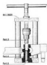
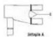
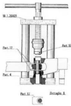
- Repeat the operation described above using the tool provided on the stem with part 16 and with part 22* in replacement of part 4, on the side opposed to that shown in the figure to reassemble the second wedging washer - roller case - sealing ring assembly.
To position the roller case on the pin (the pin end in contact with the inside bottom of the roller case) proceed as follows:
- Use the tool provided with part 20 and part 21 on the stem, as shown in the figure.
- Push the handle to move the bottom of the two roller cases in contact with the pin end.
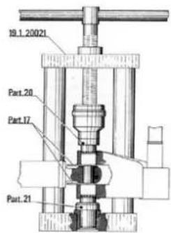
Washer wedging
- Use the tool provided with parts 3 and 4, as explained for the assembly of the pin, and push by the handle to obtain the wedging of the washers onto the oscillating hub.
- Remove the spacers, part 17, fill with grease the compartment between the sterling tube and the oscillating hub, and place the dust guard rings into said compartment.
Shock absorbers
Removal
Proceed as follows:
- Rest the vehicle on the central stand;
- Remove the trunk rack
- Slightly raise the engine by a jack to free both shock absorbers;
- Remove the silencer;
- Loosen the shock absorber spring unit fastening screw from the support fixed to the engine and from that fixed to the silencer support;
- Loosen the two top nuts (one by side) fixing the shock absorber spring unit to the chassis and re-
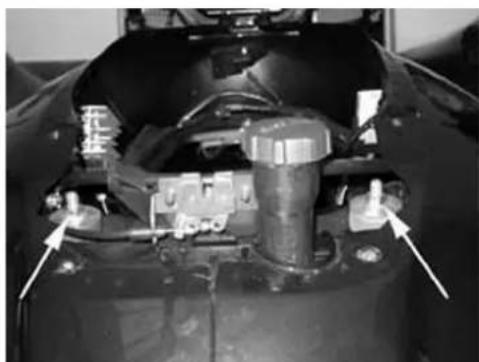
natural_image
Close-up of a mechanical component with no visible text or symbolsmove the shock absorbers.
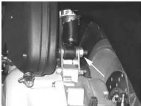
natural_image
Close-up of mechanical components with no visible text or symbols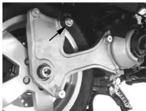
natural_image
Close-up of a mechanical assembly with no visible text or symbolsRefitting
Perform the operations for removal in the reverse order according to the proper tightening torques.
Locking torques (N*m)
Shock absorber bottom fastening screw 33 ÷ 41 in Nm Shock absorber top fastening screw 20 ÷ 25 Nm
Exhaust bracket
Removal
- Remove the silencer
- Remove the two screws fixing the bracket to the engine crankcase
- Remove the split pin, the key cap and the rear wheel axle fixing nut with the spacer
- Remove the bottom shock absorber fixing
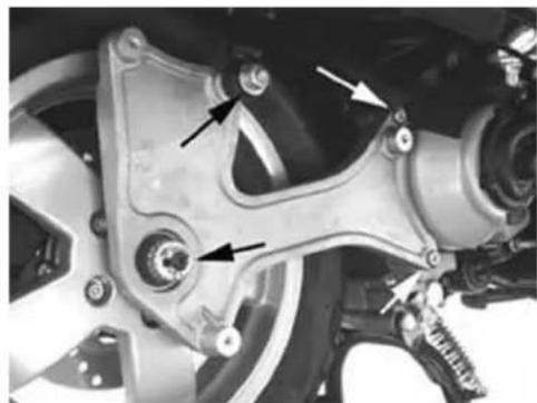
natural_image
Close-up of a motorcycle's brake system with mounting brackets and suspension components (no visible text or symbols)Refitting
- For re-assembly, perform the operations for removal in the reverse order according to the tightening torque
LockingBtorquesB(N\*m)
Screw fixing the bracket to the engine crankcase: 20 ÷ 25 Nm Shock absorber bottom fixing 33B÷B41BWheelBaxleBnutB104B÷B126BNm
Centre-stand
REMOVAL
- Suitably support the vehicle by the jack.
- Remove the 2 stand return springs.
- Loosen the nut shown in the figure.
- Remove the right side pin.
- Remove the stand.
- Upon reassembly, tighten the nut at the prescribed torque.
REASSEMBLY
- Upon reassembly, tighten the nut at the prescribed torque.
LockingBtorquesB(N\*m)
CentralBstandBfasteningBboltB25B÷30BNm
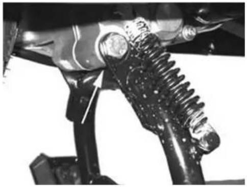
natural_image
Close-up of mechanical components including a worm gear and vehicle suspension (no visible text or symbols)SideBstand
REMOVAL
- Release the stand return springs;
- Remove the screw shown in the figure;
ASSEMBLY
For re-assembly, perform the operations for removal in the reverse order according to the tightening torque.
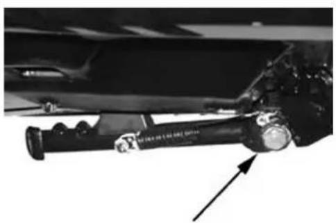
natural_image
Close-up of a mechanical suspension or lifting device with an arrow pointing to it (no visible text or symbols)LockingBtorquesB(N\*m)
SideBstandBfasteningBboltB40B÷B45BNm
INDEXBOFBTOPICS
BRAKINGBSYSTEMB
This section describes the braking system components.
RearBbrakeBcalliper
Removal
- Remove the rear wheel.
- Remove the pads retain pin.
- Using a plug, partly extract the pads retain pin.
- Remove the two screws fixing the brake caliper to the crankcase, then remove the brake caliper with pipe.
- Fully extract the pads retain pin, spring and pads.
N.B.
IFBTHEBBRAKEBCALIPERBREQUIRESBOVERHAULINGBORBREPLACEMENT,BLOOSENBTHEBOILBUNION FIXINGBBEFOREBREMOVINGBTHEBCALIPERBAT-TACHMENTSBTOBTHEBSUPPORTBBRACKETBAFTER EMPTYINGBTHEBCIRCUITBSYSTEM.
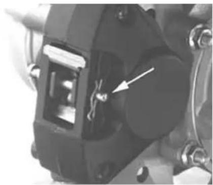
natural_image
Close-up of a mechanical component with a white arrow pointing to a specific part (no visible text or symbols)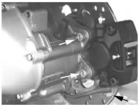
natural_image
Close-up of mechanical components with no visible text or symbolsOverhaul
- Remove the rear brake caliper
- Properly support the brake caliper in vice.
- Remove the two caliper coupling screws as shown in the figure
- Remove the two pistons from the caliper body with the aid of small compressed air jets through the brake fluid feeding holes
- Remove the dust guard ring and the sealing ring of each half-caliper.
- Remove the two sealing rings in the half-caliper. N.B.
DOBNOTBSCRATCHBTHEBHALF-CALIPERBSEATS
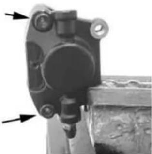
natural_image
Close-up of a mechanical component with two arrows pointing to features (no visible text or symbols)WHILEBREMOVINGBTHEBRINGS.
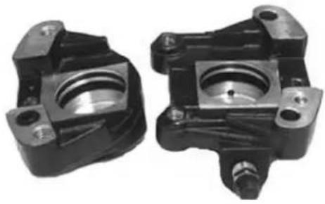
natural_image
Two black mechanical components with mounting holes and central bore (no visible text or symbols)- Check that the pistons and relevant seats exhibit no scratches.
- Wash and carefully blow all components.
- Fit new sealing rings and dust guards.
- Replace the pistons into their seats and lubricate with brake fluid.
- Couple the half-caliper and tighten the two screws at the prescribed torque.
LockingBtorquesB(N\*m)
CaliperBcouplingBscrewsB22B÷B27BNm
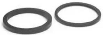
natural_image
Two black rubber rings on a white background (no text or symbols)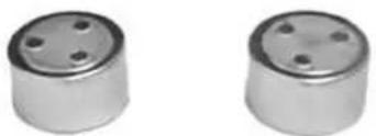
natural_image
Two cylindrical metallic components with four holes, shown side by side (no text or symbols visible)Refitting
- Introduce the brake pads into the caliper
- Insert the pad fixing pin and the retain spring arranging its ends facing the bleed screw as shown in the figure.
- Insert the lock on the pad fixing pin
N.B.
ABWRONGBPOSITIONINGBOFBTHEBPADSBACCORDINGBTOBTHEBDIRECTIONBOFBROTATIONBCANBIM-PAIRBTHEBBRAKEBPERFORMANCEBANDBNOISELESSNESS.
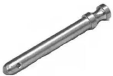
natural_image
Metal mechanical component with a flanged shaft and pointed end (no text or symbols visible)- Keep the pads in contact with the pistons and insert the caliper into the brake disc.
- Fasten the caliper to the crankcase by the two screws with spring washer, as shown in the figure
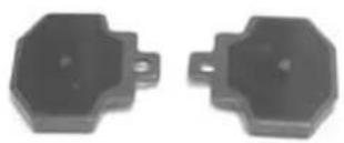
natural_image
Two black octagonal mechanical components with mounting holes (no text or symbols visible)- Fasten the brake pipe union to the caliper and tighten at the prescribed torque
- Bleed the system and replace the rear wheel
LockingBtorquesB(N\*m)
BrakeBcaliperBsupportBfixingBscrewsB20B÷B25 NmBBrakeBpipeBunion:B20÷25BN•m
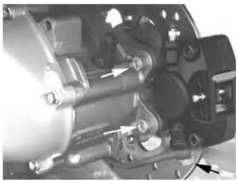
natural_image
Close-up of mechanical components with arrows indicating parts of a device (no visible text or symbols)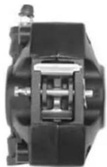
natural_image
Close-up of a mechanical component with no visible text or symbols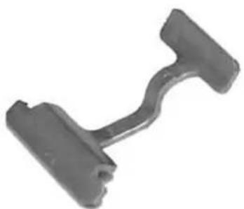
natural_image
Metal mechanical component with two protruding ends and a curved end (no text or symbols visible)FrontBbrakeBcalliper
Removal
- Remove the front wheel
- Partially loosen the two pad fixing pins
- Remove the two front brake caliper attachments from the support as shown in the figure
N.B.
IFBTHEBCALIPERBNEEDSBOVERHAULINGBORBREPLACEMENT.BLOOSENBTHEBPIPEBUNIONBFROM THEBBRAKEBCALIPERBINADVANCE.
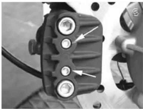
natural_image
Close-up of a mechanical component with three circular ports and white arrows pointing to features (no visible text or symbols)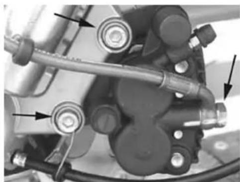
natural_image
Mechanical assembly diagram showing hoses and components with arrows indicating motion direction (no text or labels)Overhaul
Proceed as follows:
1) remove the two hexagon screws (1) and extract the two pads (10);
2) remove the two hexagon screws (2) and remove the reaction plate (3);
3) extract the fixed plate (4) from the guides;
4) remove the internal parts from the floating body (5) using small jets of compressed air through the brake fluid duct to facilitate the ejection of the pistons (6).
5) Check:
- that plates and body are in good working order;
- that the cylinders of the caliper floating body exhibit no scratches or erosion; otherwise, replace the entire caliper;
- that the fixed plate guides exhibit no scratches or erosions; otherwise, replace the plate;
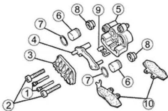
- that the pads locking bracket is efficient
CAUTION
ALLBINTERNALBCOMPONENTSBMUSTBBEBRE- NEWEDBATBEACHBCALLIPERBOVERHAUL.
TheBpadsBlockingBbracket
- pads fixing screws
- reaction plate fixing screws
- reaction plate
- fixed plate
- floating body
- piston
- piston sealing rings
- guide protection rubber caps
- pads locking bracket
- pads
Refitting
Introduce in the front caliper body:
- Sealing rings and pistons (1).
- Replace the plate (2).
- Position the pads retaining spring (3).
- Replace the pads and vent the air.
- Place the caliper on the disc and lock it to the support tightening the bolts at the prescribed torque.
- Tighten the pipe union to the caliper at the prescribed torque.
- Perform the same operations for the rear brake caliper.
LockingBtorquesB(N\*m)
ScrewBfixingBtheBfrontBcaliperBtoBtheBsupport: 20B÷B25BNmBScrewBfixingBtheBoilBunionBtoBthe caliper:B20B÷B25BNm
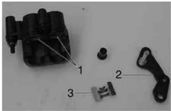
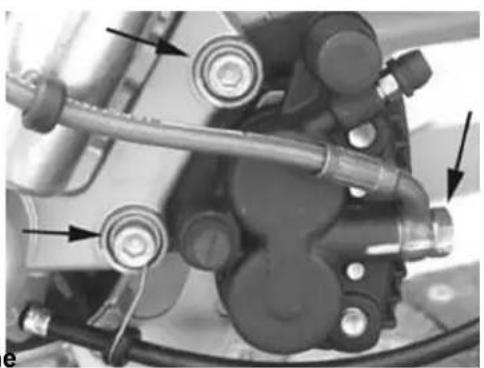
natural_image
Mechanical assembly diagram showing components like hoses, springs, and actuators (no text or labels visible)RearBbrakeBdisc
Removal
- Remove the rear brake caliper
- Remove the wheel axle and the brake disc with hub
- To remove the brake disc from the hub, support the unit in a vice and tighten the 5 fixing screws with shown in the figure
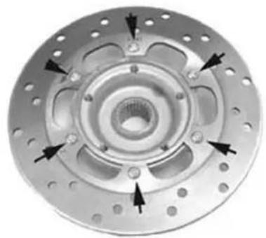
natural_image
Close-up of a metallic brake disc with multiple bolt holes and mounting holes (no text or symbols visible)Refitting
- To re-assemble the brake disc on the hub, carry out the removal operations in the reverse order arranging the brake disc on the hub on the side opposed the wheel keying
- Follow the direction of rotation shown by the arrow and tighten at the prescribed torque.
- Insert the hub - disc assembly in the wheel axle
Locking torques (N*m)
Disc to the hub 11÷13 Nm
Disc Inspection
- Remove the rear brake caliper
- Using a micrometer, check the disc thickness
Characteristic
Minimum admissible thickness after use:
XXX
Standard thickness:
4 +0,2 -0,2mm
- Repeat the measurement in at least 6 points of the disc.
- Check that the brake disc unit rotates regularly using the specific tool fixed on the brake caliper support as shown in the figure.
- To fix the specific tool, use a metal plate with threaded hole M8 and secure it to one of the two rear brake caliper couplings
- Suitably fasten the flange on the wheel axle by a nut and the original spacer, and a ∅ 17 mm bearing
N.B.
TOBAVOIDBWRONGBMEASURESBITBISBPREFERABLEBTOBGENERATEBTHEBDISCBROTATIONBBYBROTATING THEBDRIVENBPULLEYBAXLE.
SpecificBtooling
020335YBMagneticBstandBandBcomparator
Characteristic
MaxBadmissibleBdeviation:
0,1 mm
- In case of irregular values, replace the disc. If the fault continues, replace the hub.
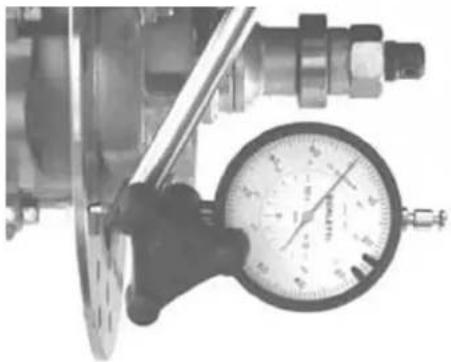
natural_image
Close-up of a pressure gauge attached to a mechanical component (no visible text or symbols)FrontBbrakeBdisc
Removal
- Remove the front wheel
- Remove the front brake caliper
- Remove the hub with disc by releasing the wheel axle nut
- Suitably support the hub with disc and release the six screws shown in the figure to remove the brake disc
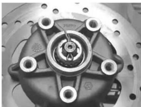
natural_image
Close-up of a mechanical brake disc with mounting holes and central hub (no visible text or symbols)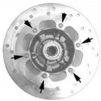
natural_image
Top-down view of a mechanical component with multiple circular cavities and black arrows indicating direction (no text or symbols)Refitting
- Perform the removal operations in the reverse order according to the direction of rotation of the disc, as shown by the arrow on the disc - Tighten the 6 screws at the prescribed torque
LockingBtorquesB(N*m)
BrakeBdiscBscrews:B6B+0,5B-1BNm

natural_image
Close-up of a mechanical component with multiple blades and central hub, no visible text or symbolsDiscBInspection
- Remove the front wheel
- Using a micrometer, check the disc thickness as shown in the figure.
- Repeat the measurement in at least 6 points of the disc
- Remove the front brake caliper
- To fix the specific tool, use a metal plate with threaded hole M8 and secure it to one of the two front brake caliper couplings
- Place the comparator on the disc outside edge
- Turn the wheel hub and check the disc deviation
SpecificBtooling
020335YBMagneticBstandBandBcomparator
Characteristic
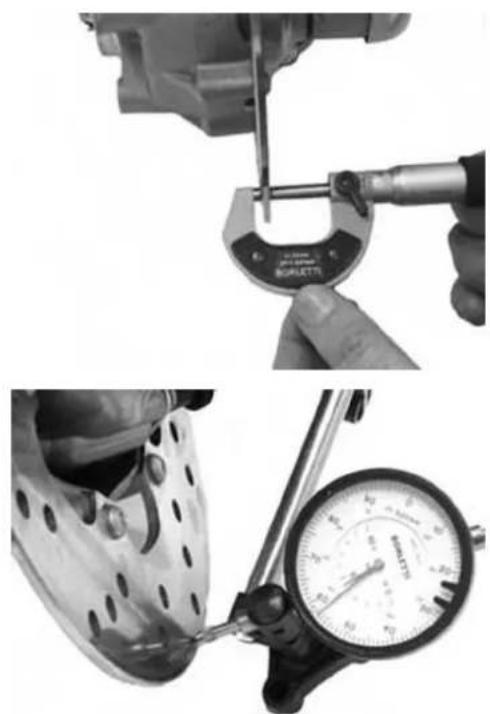
natural_image
Two-panel black-and-white photo showing a micrometer measuring the tool and a foot using a footwatch (no visible text or symbols)Standard thickness:
4 +0,2 -0,2mm
Max admissible deviation:
0,1 mm
Front brake pads
Removal
- Remove the front wheel
- Partially loosen the two brake pad fixing pins
- Remove the brake caliper
- Remove the two pad fixing pins completely
- Check that there are no deformations or wear.
Replace them, if necessary - Check that the thickness of the friction material is more than 1.5 ~mm . Replace them, if necessary
- The material should also be replaced in case of higher residual thickness if the pad is not evenly worn. A residual friction material thickness difference of 0.5 mm is allowed
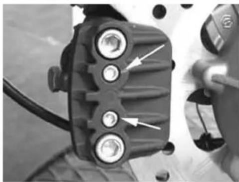
natural_image
Close-up of a mechanical component with three circular ports and directional arrows indicating features (no text or symbols visible)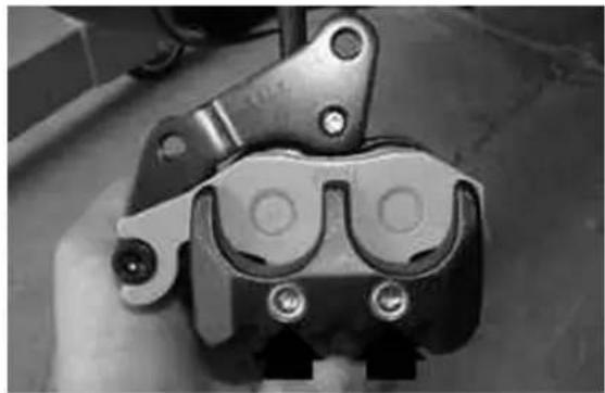
natural_image
Close-up of a mechanical clamp or bracket component with mounting holes and bolts (no visible text or symbols)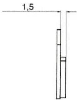
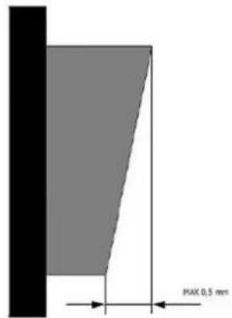
Refitting
To refit the pads, follow these steps:
- Place the two pads inside the caliper.
- Tighten the pad fastening pins with the prescribed torque after applying threadlocking.
- Fit the caliper on its support and tighten the two screws with the prescribed torque.
N.B.
SHOULD YOU FIND ANY DIFFICULTY POSITIONING THE CALIPER ON THE DISC, GENTLY PART THE BRAKEBPADS.
RecommendedBproducts
LoctiteB243BThread-Brake
Medium Loctite Thread-Brake 243
LockingBtorquesB(N*m)
Screw fixing the caliper to the support 20 ÷ 25 Pad clamping pin 19,6 ÷ 24,5
RearBbrakeBpads
Removal
- Remove the rear brake caliper
- Remove the brake pads and check that there are no deformations or wear. Replace them, if necessary
- Check that the thickness of the friction material is more than 1.5 mm. Replace them, if necessary
- The material should also be replaced in case of higher residual thickness if the pad is not evenly
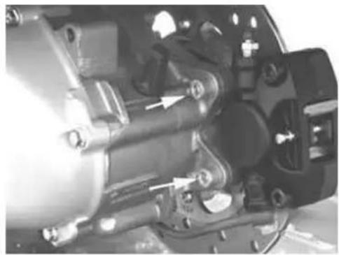
natural_image
Close-up of mechanical components with no visible text or symbolsworn. A residual friction material thickness difference of 0.5 mm is allowed
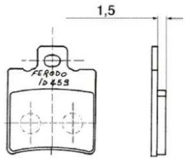
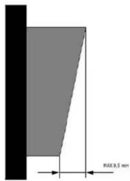
See also
Removal
Refitting
- Introduce the brake pads
- Insert the pad fixing pin and the retain spring with its ends facing the bleed screw as shown in the figure.
- Insert the stop onto the pin
- Fasten the rear brake caliper to the bracket and tighten the 2 screws at the prescribed torque.
Locking torques (N*m)
Rear brake caliper fastening screws 20 ÷ 25 Nm
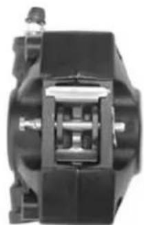
natural_image
Close-up of a mechanical component with no visible text or symbols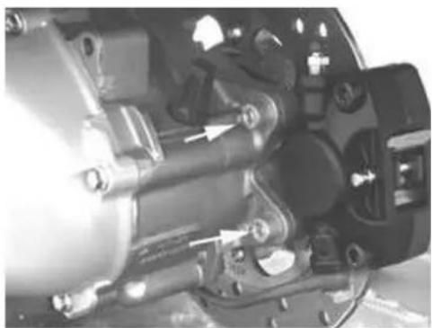
natural_image
Close-up of mechanical components with no visible text or symbolsFill
Front
- Remove the rubber cap from the bleeding screw.
- Insert a rubber pipe in the bleeding screw to allow recovering the brake fluid.
- Move the LH brake lever to load the system and put it under pressure.
- Keep the LH lever actuated and loosen the bleeding screw to allow the exit of the system inside air. Tighten the bleeding screw
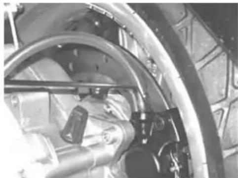
natural_image
Close-up of an aircraft fuselage with visible mechanical components and structural framing (no text or symbols)- Repeat the operation until only brake fluid comes out of the rubber pipe.
- Remove the fluid recovery pipe and fit the rubber cap on the bleeding screw.
- Restore the brake fluid level in the tank It is possible to bleed by a specific vacuum pump, if required.
N.B.
DURINGBBLEEDING,BAVOIDBANYBCONTACTBBETWEENBTHEBBRAKEBFLUIDBANDBTHEBBODYBTOBPREVENTBDAMAGES.BALSO,BWHILEBBLEEDINGBTHEBBRAKEBCALIPERBAVOIDBANYBCONTACTBBETWEEN THEBFLUIDBANDBTHEBBRAKEBDISCSBORBPADS.BFAILUREBTOOBSERVEBTHISBPRECAUTIONBAFFECTS THEBBRAKINGBSYSTEMPERFORMANCE.
SpecificBtooling
020329YBPumpBMITYVAC
LockingBtorquesB(N*m)
SystemBbleedBcaliperBunion:B20B÷B25BNm
BrakeBfluidBlevelBcheck
- Rest the vehicle on a flat ground and on the central stand.
- Remove the brake pump cover as shown in the figure
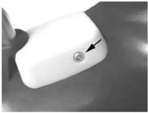
natural_image
Close-up of a white plastic door handle with a circular button and an arrow pointing to it (no text or symbols visible)- Check the brake fluid level by the special indicator located on the pump, as shown in the figure
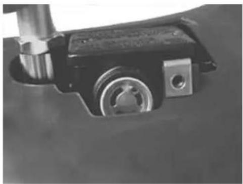
natural_image
Close-up of a mechanical component with metallic parts and a cylindrical shaft (no visible text or symbols)- If the level is below minimum, fill by the screws shown in the figures
- Remove the gasket and fill with fluid DOT 4 to fully cover the indicator
CAUTION
KEEPBTHEBBRAKEBFLUIDBAWAYBFROMBTHEBSKIN, THEBEYESBANDBCLOTHING.BINBCASEBOFBCONTACT,BRINSEBGENEROUSLYBWITHBWATER.
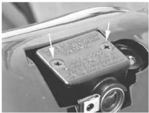
natural_image
Close-up of a car's front camera module with no visible text or symbols
THEBBRAKINGBCIRCUITBFLUIDBHASBABHIGHBCORROSIVEBPOWER.BTHEREFORE,BDURINGBANY LEVELBTOPBUPBOPERATIONS,BAVOIDBLETTINGBIT COMEBINTOBCONTACTBWITHBTHEBPAINTEDBPARTS. THEBBRAKINGBCIRCUITBFLUIDBISBHYGROSCOPIC, THATBISBTOBSAYBITBABSORBSBHUMIDITYBFROM THEBSURROUNDINGBAIR,BIFBTHEBHUMIDITYBCONTAINEDBINBTHEBBRAKEBFLUIDBISBOVERBABCERTAIN VALUEBITBWILLBRESULTBINBUNSATISFACTORY BRAKING.
CAUTION
THEBBRAKINGBCIRCUITBFLUIDBISBHYGROSCOPIC,
I.E., BITBABSORBSBHUMIDITYBFROMBTHEBSUR-ROUNDINGBAIR.BIFBTHEBHUMIDITYBINBTHEBBRAKINGBFLUIDBEXCEEDSBABCERTAINBVALUE,BITBWILLLEADBTOBINEFFICIENTBBRAKING.
LockingBtorquesB(N*m)
TankBscrews:B15B÷B20BNm
Never use braking fluid from containers that have already been opened, or partially used.
In normal weather conditions, the fluid should be replaced every 20,000 km or in any case every 2 years.
For re-assembly, perform the operations for removal in the reverse order according to the tightening torques of the tank cover screws.

natural_image
Close-up of a mechanical device with a transparent housing and mounting holes (no visible text or symbols)FrontBbrakeBpump
Removal
- Remove the rear handlebar cover
- Remove the two screws fixing the brake pump to the handlebar, as shown in the figure.
- Remove the oil pipe union from the pump
- Remove the connector from the parking light switch
BRAKEBPUMPBTECHNICALBDATA:
SpecificationBDesc./Quantity
| RH pump piston diameter | ∅ 12,7 |
| LH pump piston diameter | ∅ 11 |
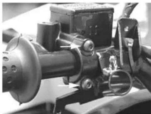
natural_image
Close-up of mechanical components with no visible text or symbols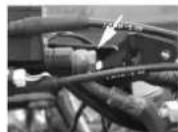
Overhaul
Proceed as follows:
1) remove the brake lever releasing the fixing screw; open the cover (2) and recover the membrane (3);
2) unscrew the cap (4) and extract the internal components in a sequence;
3) check that:
- the pump body exhibits no internal scratches or corrosion;
- the piston exhibits no abnormal wear or scratches;
the piston return spring is in good working order.
CAUTION
ANYBTIMEBTHEBPUMPBISBOVERHAULED, BALLBSEALINGBCOMPONENTSBMUSTBBEBREPLACED.
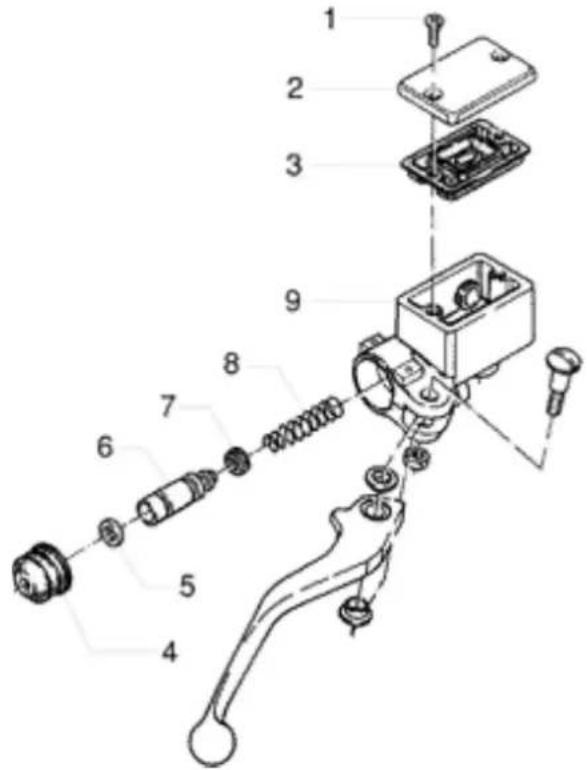
- Tank cap screw.
- Tank cap.
- Membrane.
- Bellows.
- Sealing ring.
- Piston.
- Gasket.
- Spring.
- Tank
Refitting
For re-assembly, perform the operations for removal in the reverse order according to the tightening
torques.
Locking torques (N*m)
Oil piping union to pump: 20÷25 Screws fixing the brake pump to the handlebar: 7 ÷ 10 Nm
INDEX OF TOPICS
COOLING SYSTEM
WaterBpumpB-Boverhaul WaterBpumpBassembly
- Using the thermal gun drawing, heat the fly-wheel cover from the internal side.
CAUTION
DOBNOTBHEATBTOOBMUCHBASBTHISBMAYBCAUSE ALTERATIONSBTOBTHEBPAINTEDBSURFACE.
SpecificBtooling
020151YBAirBheaterB"METABOBHGB1500/2"
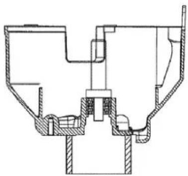
natural_image
Cross-sectional technical drawing of a mechanical assembly (no text or labels)- Place the flywheel cover on the ring base in a way similar to the removal steps.
- Place the pair of bearings on the specific punch.
N.B.
ONBREASSEMBLY, BALWAYSBUSEBABNEWBBEARING.
- Keep the bearings on the specific tool by grease.
- Insert the bearings into the crankcase to travel end, using a plastic mallet.
- Assemble the ceramic ring and the relevant rubber gasket. The chamfering of the ceramic ring must face the gasket.
- Lubricate the rubber gasket and insert the unit on the flywheel cover.
- If necessary, manually use the punch of the specific tool.
CAUTION
ALWAYSBUSEBNEWBGASKETBANDBCERAMICBRING. ABNON-MANUALBASSEMBLYBOFBTHEBCERAMIC SEALINGBRINGBCOULDBDAMAGEBTHEBSAME.
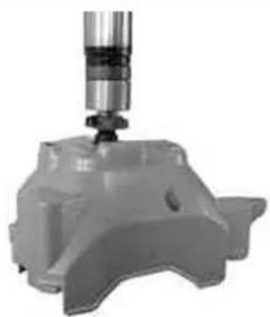
natural_image
3D rendered mechanical component with a cylindrical tool inserted, no visible text or symbolsSpecificBtooling
020440YBWaterBpumpBoverhaulBtool
- Insert the drive on the guiding pin of the support base of the specific tool, with the convex part fa-
cing upwards.
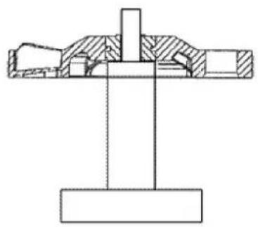
natural_image
Cross-sectional technical drawing of a mechanical assembly (no text or symbols)- Insert the flywheel cover with the bearings on the specific tool.
- Insert the shaft with mechanical seal on the bearings.
- Using the specific punch and the press, insert the shaft into the bearings and into the drive to the travel end of the specific tool.
N.B.
PERFECTLYBCENTREBTHEBPUNCHBONBTHEBIM- PELLER.BMOVEBTHEBSHAFTBANDBCHECKBTHAT THEBFLYWHEELBCOVERBTURNSBINBPLANE.BFAIL- UREBTOBOBSERVEBTTHISBREGULATIONBCANBDAM- AGEBTHEBDRIVE.
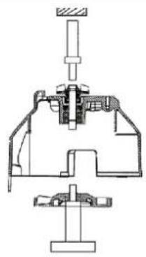
natural_image
Technical line drawing of a mechanical assembly with no visible text or symbols- Replace the impeller cover using a new O-Ring.
- Tighten the 3 fixing screws at the torque below:
N.B.
DOBNOTBLUBRICATEBTHEBO-RING.BFAILUREBTO OBSERVEBTHISBRULEBCAUSESBABDEFORMATION OFBTHEBRING.
LockingBtorquesB(N*m)
WaterBpumpBcoverBscrewsB3B÷B4
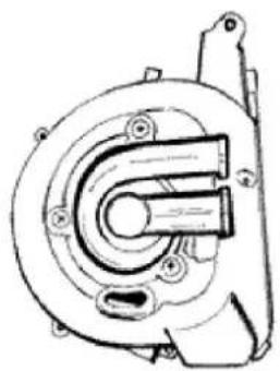
natural_image
Technical line drawing of a mechanical component with no visible text or symbolsRemoval
- In case of noise of the bearings or fluid leaks from the inside drainage hole, proceed to the water pump overhaul.
- Remove the flywheel cover with the water pump from the engine.
- Remove the impeller cover loosening the 3 screws shown in the figure.
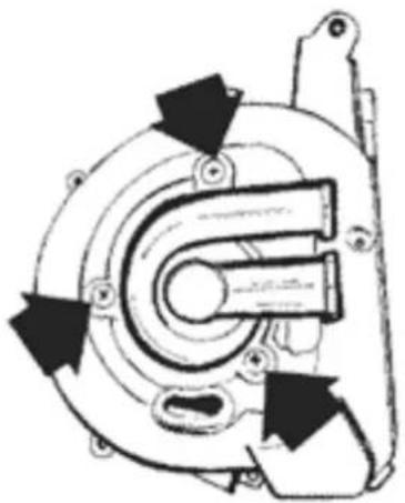
natural_image
Mechanical component diagram showing a U-shaped housing with directional arrows indicating motion (no text or symbols)- Place the flywheel cover on the ring base of the tool.
N.B.
INBORDERBTOBAVOIDBDAMAGESBTOBTHEBCOVERBSURFACEBSERVINGBTOBEXECUTEBTHEBCOOLANTBFLUIDBSEAL,BUSEBTHEBRINGBBASEBWITHBTHEBPRECISELYBWORKEDBSURFACEBTURNEDBTOBTHEBFLYWHEELBCOVER.
SpecificBtooling
020440YBWaterBpumpBoverhaulBtool
- Using a press and the punch of the specific tool, eject the shaft with impeller from the drive and from the bearings.
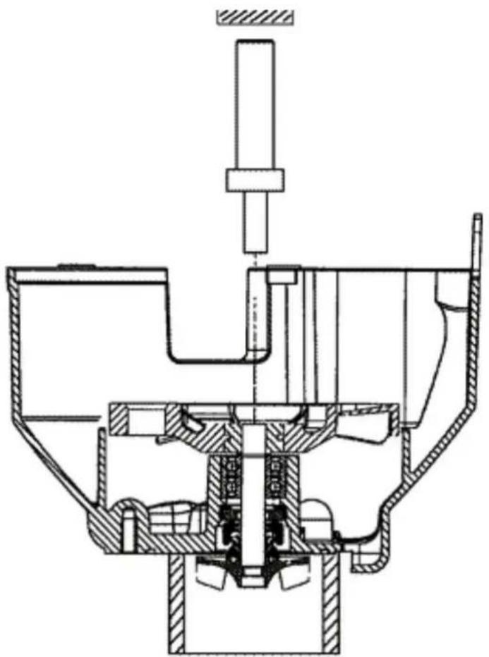
natural_image
Cross-sectional technical drawing of a mechanical assembly (no text or labels visible)- Using a screwdriver, remove the static portion of the ceramic seal from the flywheel cover.
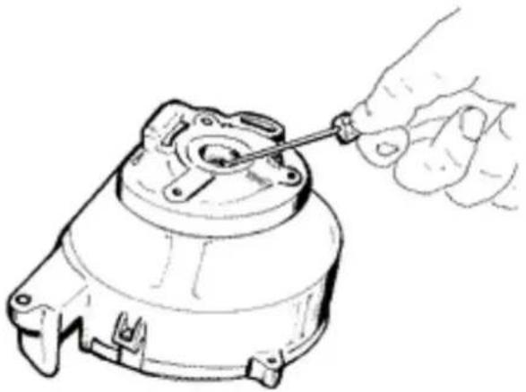
natural_image
Line drawing of a hand using a tool to adjust or install a mechanical component (no text or symbols present)- Place the flywheel cover under the press checking that it is perfectly in plane.
- Using the punch in reverse position, eject the two ball bearings.
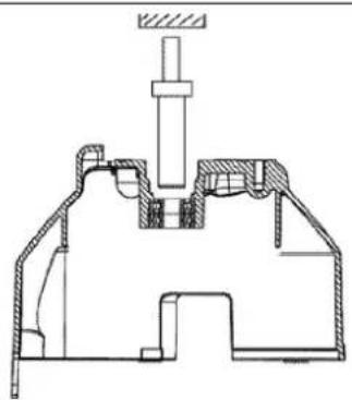
natural_image
Technical cross-sectional diagram of a mechanical assembly (no text or labels)Water pump ceramic seal
Our Leader, Quasar, and Master liquid cooled engines are equipped with water pumps fitted with the ceramic seal in the subject. Such component must guarantee the seal around the pump shaft. This is achieved via two special ceramics, a static one and a spinning one, kept in contact by the thrust of a spring, coaxially mounted onto the pump shaft. The efficiency of this system is guaranteed by the accurate machining and cleaning of the components as they are fitted; in any case, ceramic seals are subjected to a running in period. During this period (1,000 ± 1,500 Km), there may be small leakages through draining holes, which remain visible on the aluminium crankcase. This phenomenon is particularly visible there where the hole is more exposed (Quasar and Master). In these cases, it is suggested that the crankcase be cleaned and the sealing be checked after 1,500 Km. Following persisting leaks, it is possible to replace the ceramic seal. For these operations, attain to the tools and instructions given in the relevant service station manuals.
Note: The ceramic seal may be overhauled according to the following couplings:
• Coupling "A": seal ring no. 485084 with ceramic seal no. 486216
• Coupling "B": seal ring no. 841329 with ceramic seal no. 841330
The couplings above may be selected according to their availability, as they are interchangeable.
Component check
- Check that the impeller is free from abnormal wear or cracks;
- Check that the impeller shaft is not oxidised;
- Check that the ceramic seal and nearing seats are free from oxidation;
- Check that the drive is free from cracks and perfectly integral with the steel hub.
INDEX OF TOPICS
CHASSIS
This section provides information on the operations that may the carried out on the vehicle body.
Seat
- Remove the helmet compartment
- Remove the two nuts shown in the figure
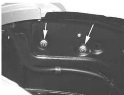
natural_image
Close-up of a mechanical component with two circular ports and directional arrows indicating features (no text or symbols visible)- Release the electric wiring from the retaining clips shown in the figure
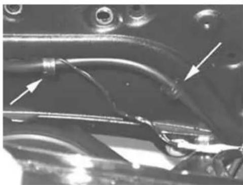
natural_image
Close-up of mechanical components with visible wiring and arrows indicating features (no text or symbols)- Remove the transmission - saddle opener cable - Remove the manual saddle opening control - transmission cable.
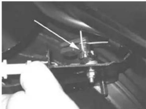
natural_image
Close-up of a mechanical component with a hand holding a tool, no visible text or symbols- Remove the electric connector from the saddle opening actuator
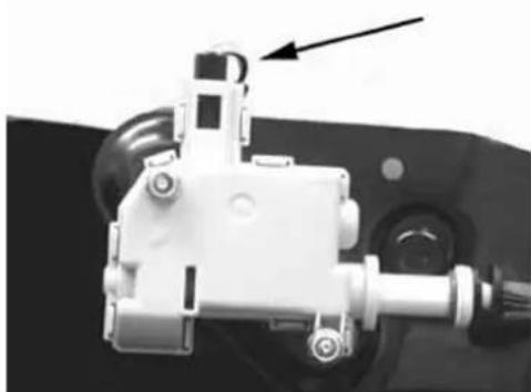
natural_image
Mechanical component with a highlighted section and arrow indicator (no visible text or symbols)- Remove the two screws shown in the figure
- Remove the peg from the transmission
- Remove the actuator from the support bracket
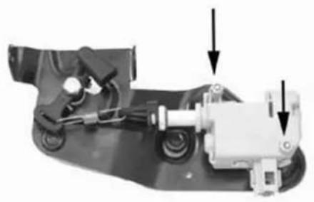
natural_image
Mechanical assembly diagram showing a motor and housing components with arrows indicating motion direction (no text or symbols present)- Remove the helmet compartment
- Remove the two screws shown in the figure
- Remove the saddle
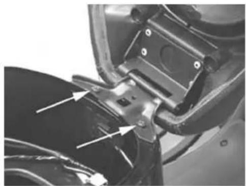
natural_image
Close-up of a motorcycle's wheel assembly with visible brackets and mounting points (no text or symbols)Rear rack
- Remove the helmet compartment
- Release the two screws shown in the figure and remove the trunk rack cover
- Release the six screws shown in the figure, then remove the trunk rack and the passenger handles
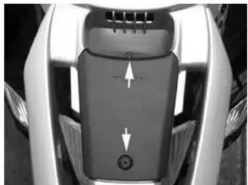
natural_image
Close-up of a car interior panel showing a black plastic seat with directional arrows indicating movement or force (no text or symbols visible)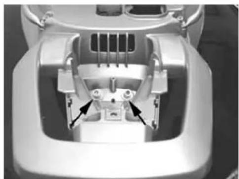
natural_image
Top-down view of a car headgear component with visible internal parts and mounting holes (no text or symbols)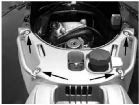
natural_image
Close-up of a car's engine compartment showing internal components and airflow direction arrows (no text or symbols)Rear handlebar cover
- Remove the front handlebar cover
- Loosen the 4 screws shown in the figure
- Disconnect the odometer cable
- Remove the rear handlebar cover after disconnecting the electric wirings.
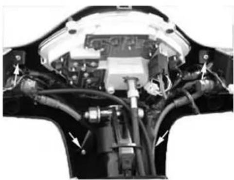
natural_image
Close-up of a car's internal engine bay with visible hoses and components (no text or symbols)Instrument panel
- Remove the rear handlebar cover;
- Remove the four screws shown in the figure
- Remove the instrument unit.
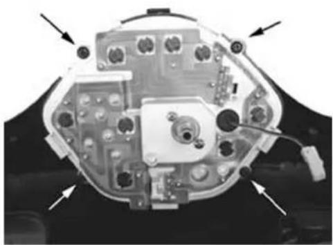
natural_image
Top-down view of a computer mouse head with visible internal components and directional arrows indicating motion (no text or symbols)Front handlebar cover
- Remove the front radiator grill
- Remove the front screw shown in the figure
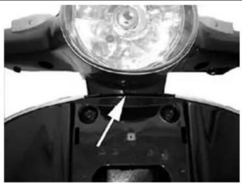
natural_image
Close-up of a mechanical component with a circular headlight and mounting holes, showing no visible text or symbols.- Loosen the 2 screws shown in the figure;
- Remove the front handlebar cover.
- Disconnect the front headlight connectors
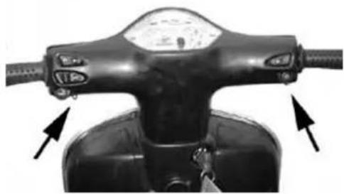
natural_image
Top-down view of a black scooter's front wheel and steering wheel (no visible text or symbols)Headlight assy.
- Release the screw shown in the figure to remove the rear direction indicator
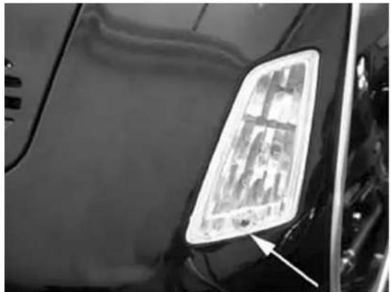
natural_image
Close-up of a vehicle's front side panel showing a highlighted rectangular light fixture (no text or symbols visible)Knee-guard
- Remove the rear handlebar cover
- Remove the two screws onto the shield below the radiator grill, as shown in the figure
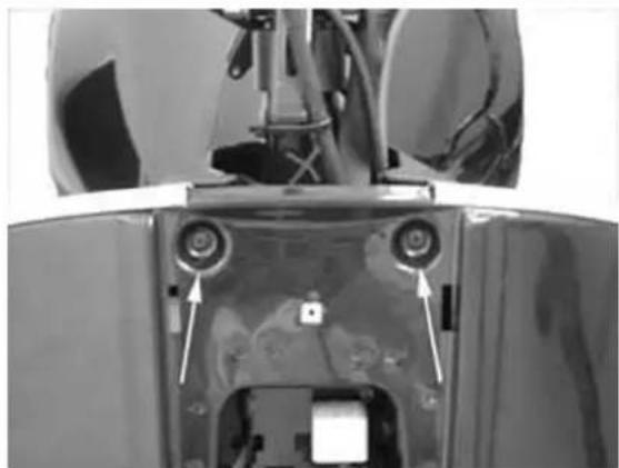
natural_image
Close-up of a mechanical component with two circular components and directional arrows indicating features (no visible text or symbols)- Remove the expansion tank cover and remove the expansion tank cap
- Remove the central screw inside the trunk as shown in the figure
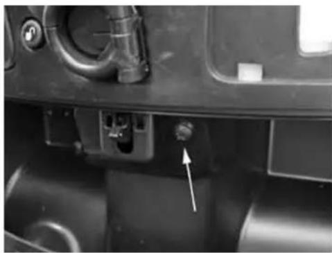
natural_image
Close-up of a mechanical component with a white arrow pointing to a small knob or button (no visible text or symbols)- Remove the two screws shown in the figure and respectively located under the expansion tank cover and under the left cover
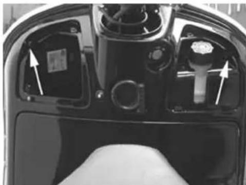
natural_image
Close-up of a car head panel showing internal components with arrows indicating movement or assembly (no text or symbols visible)- Remove the bottom counter-shield screws on both the right and left of the counter-shield, as shown in the figure
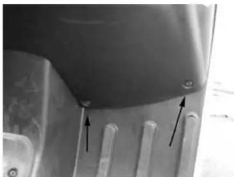
natural_image
Close-up of a metallic mechanical component with two black arrows pointing to features, no visible text or symbols.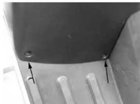
natural_image
Close-up of a metallic panel with two arrows pointing to features, no visible text or symbols- Remove the electric saddle opening button wiring, the fuse holder box and the manual saddle opening cable as shown in the figure
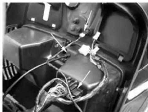
natural_image
Close-up of an automotive engine compartment with visible wiring and components (no text or symbols)Removing the ignition key-switch when on \*off\*
- Remove the knee-guard as described in the "Bodywork" chapter.
- Remove the immobiliser antenna shown in the figure.

natural_image
Close-up of hands adjusting a mechanical component with a black cap (no visible text or symbols)- Disconnect the wiring.
- Remove the key switch by extracting the locking clip shown in the figure.
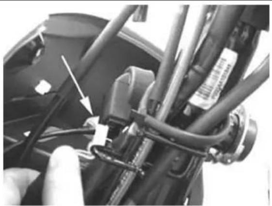
natural_image
Close-up of a mechanical assembly with visible wiring and components, no text or symbols present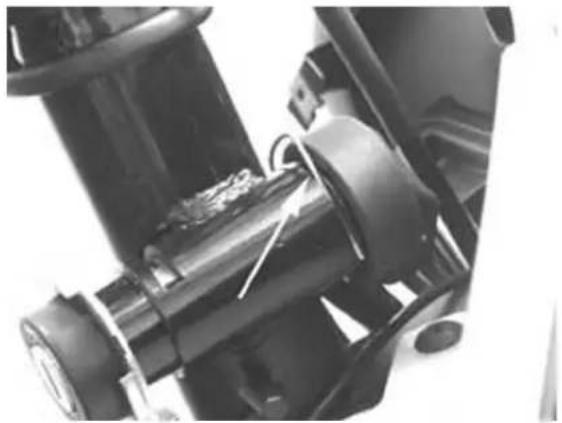
natural_image
Close-up of mechanical components with no visible text or symbols- Slightly push the cylinder and extract the stop from the threading shown in the figure.
- Pull out the cylinder fitted with lock body.
- Repeat the operations in reverse order for re- assembly

natural_image
Close-up of a mechanical component with no visible text or symbols, featuring a circular dial and a white arrow pointing to a specific part (no readable text or symbols beyond basic markings)RemovingBtheBignitionBkey-switchBwhenBonB\*lock\*
In Lock position, the cylinder locking clip cannot be accessed. Drill the clip as shown in the figure to eject the lock cylinder.
N.B.
FORBRE-ASSEMBLYBFROMBTHISBPOSITION,BRELEASEBTHEBSTEERINGBWHEELBANDBSETBTHEBLOCKBODYB(INSIDEBANDBOUTSIDEBPART)BTOB"OFF".BTHEN,BPROCEEDBASBDESCRIBEDBINBPARAGRAPHBRE-MOVAL,BLOCKBINBOFFBPOSITION.
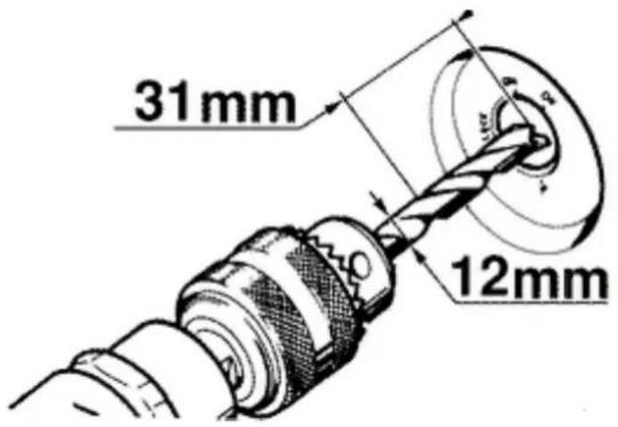
Front wheel housing
- Remove the front fork;
- Loosen the central screw fixing wheel housing to the frame;
• Detach the brake hose from the pump; - Remove the speedometer cable.
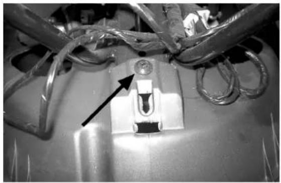
natural_image
Close-up of a mechanical component with wires and a central connector, no visible text or symbols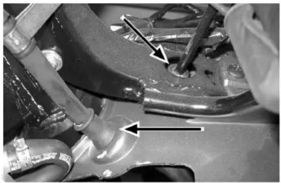
natural_image
Close-up of mechanical components with arrows indicating features (no visible text or symbols)Taillight assy.
- Release the screw shown in the figure to remove the rear direction indicator
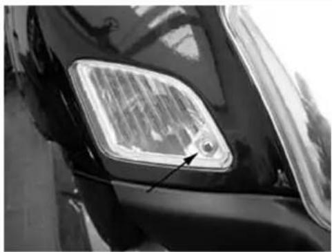
natural_image
Close-up of a car's headlight with a small arrow pointing to the corner (no visible text or symbols)- Remove the two number plate light fixing screws shown in the figure
- Release the two fixing screws and remove the rear light group
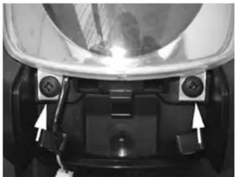
natural_image
Close-up of a car's front bumper with two white arrows pointing to the rear panel (no text or symbols visible)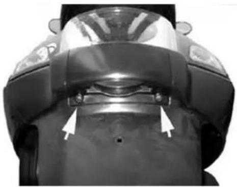
natural_image
Top-down view of a scooter's front bumper and seat, showing no text or symbols on the body (pure technical diagram)Footrest
- Remove the counter-shield
- Remove the battery compartment cover
- Remove the sides
- Remove the central screw located under the battery compartment cover as shown in the figure
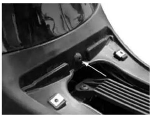
natural_image
Close-up of a car's front bumper showing internal components and a handle (no text or symbols visible)- Remove the passenger footboards by the two screws shown in the figure
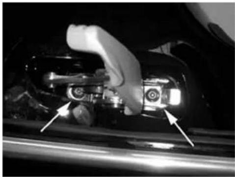
natural_image
Close-up of a hand holding a mechanical component with two arrows pointing to the interior (no visible text or symbols)- Remove the left and right side footboard fixing screw shown in the figure
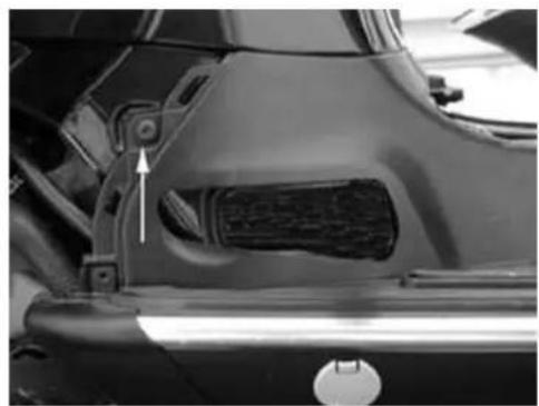
natural_image
Close-up of a car's side panel showing a textured grille and a white arrow pointing to a component (no text or symbols visible)- Remove the left and right bottom covers as shown in the figure
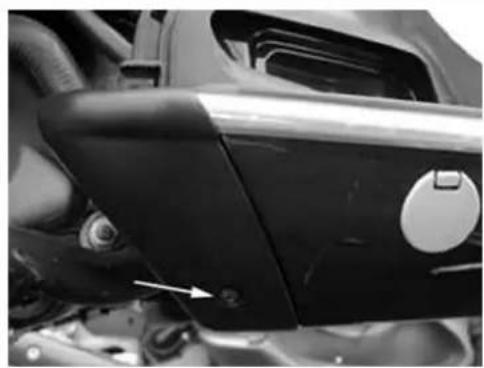
natural_image
Close-up of a car's front wheel and dashboard with a knob and arrow indicator (no visible text or symbols)- Remove the screws located under the non-slip rubber of the footboard as shown in the figure
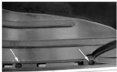
natural_image
Close-up of a car's front bumper with two white arrows pointing to the side panel (no text or symbols visible)Side fairings
- Remove the right and left sides by releasing the
2 screws shown in the figure
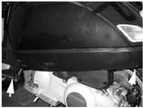
natural_image
Close-up of a car's head and engine compartment with white arrows pointing to specific parts (no visible text or symbols)Rear mudguard
- Remove the air filter
- Remove the screw shown in the figure
- Remove the mudguard
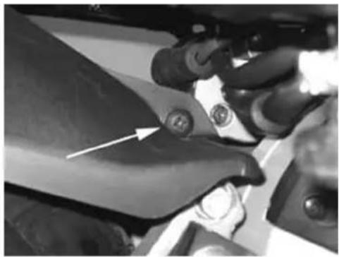
natural_image
Close-up of mechanical components with a white arrow pointing to a specific part (no visible text or symbols)Helmet bay
- Raise the saddle and remove the helmet compartment

natural_image
Close-up of a black scooter's front bumper and seat, showing no text or symbolsFuel tank
- Remove the helmet compartment
- Remove the right side
- Remove the silencer
- Remove the trunk rack
- Remove the top shock absorber attachments
- Remove the two screws fixing the tank to the body as shown in the figure
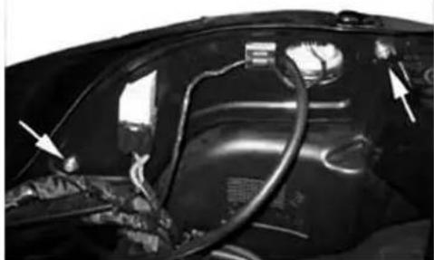
natural_image
Close-up of a car's head panel showing wiring and components (no visible text or symbols)- Remove the connector from the fuel level indicator
- Remove the screw fixing the tank to the body as shown in the figure after removing the rear light group
- Remove the clips securing the piping to the fuel tap as shown in the figure
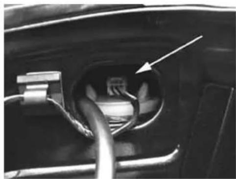
natural_image
Close-up of a car's engine compartment showing plug and socket (no text or symbols visible)- Remove the two rear direction indicators
- Using a jack, lift the body to create the necessary space between the vehicle rear side and the engine, to extract the tank
For re-assembly, perform the operations for removal in the reverse order
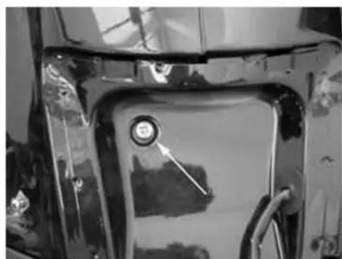
natural_image
Close-up of a metallic vehicle's front panel with a circular dial indicator (no visible text or symbols)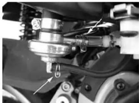
natural_image
Mechanical assembly diagram showing springs, gears, and a valve (no text or symbols visible)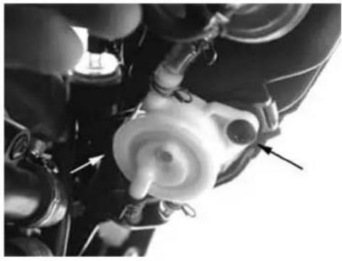
natural_image
Close-up of a mechanical component with no visible text or symbolsRear central cover
- Remove the four screws shown in the figure
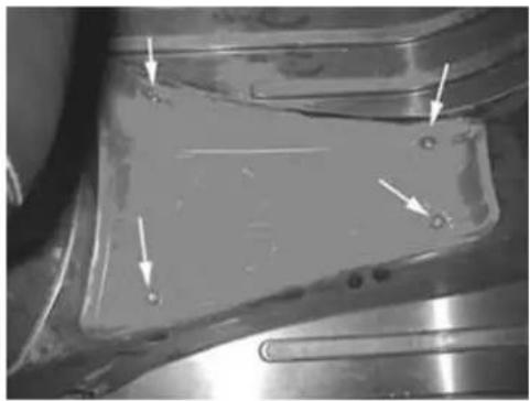
natural_image
Close-up of a metallic mechanical component with arrows pointing to features (no visible text or symbols)Front mudguard
- To remove the front mudguard, remove the steering tube and release the front brake piping from the caliper
- Then, remove the three attachments fixing the mudguard to the steering tube as shown in the figure
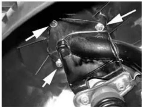
natural_image
Close-up of a mechanical component with white arrows pointing to features, no visible text or symbolsRadiator fan
- To perform the operations on the radiator unit we recommend draining the cooling fluid from the fluid inlet piping into the pump shown in the figure.
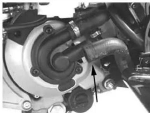
natural_image
Close-up mechanical assembly showing a valve and housing component with an arrow pointing to a specific part (no visible text or symbols)- Remove the counter-shield;
- Remove the right radiator inlet and outlet cooling fluid pipes;
- Release the 4 screws fixing the radiator to the body;
- Release the radiator
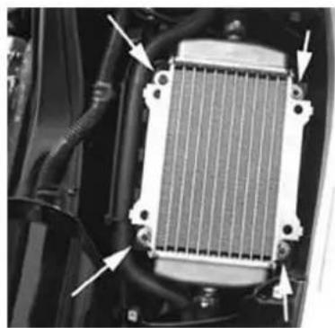
natural_image
Close-up of a car radiator component with visible cooling pipes and wiring (no text or symbols)- Release the piping from the plastic conveyor by removing the plastic clip shown in the figure. Then, remove the conveyor.
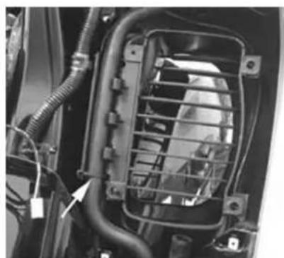
natural_image
Close-up of a car's front panel showing internal components and wiring (no visible text or symbols)- The same procedure applies to the left radiator, but the electric fan must be removed first, by releasing the 3 screws shown in the figure.
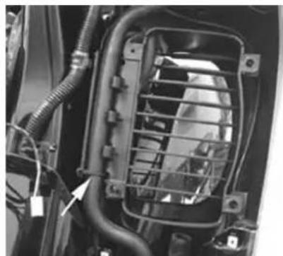
natural_image
Close-up of a car front panel with visible wiring and connectors (no text or symbols)For re-assembly, perform the operations for removal in the reverse order, applying new clips for the fluid piping and filling the cooling fluid circuit.
Front central cover
- Remove the «PIAGGIO» logo
- Release the screw shown in the figure
- Remove the radiator grill
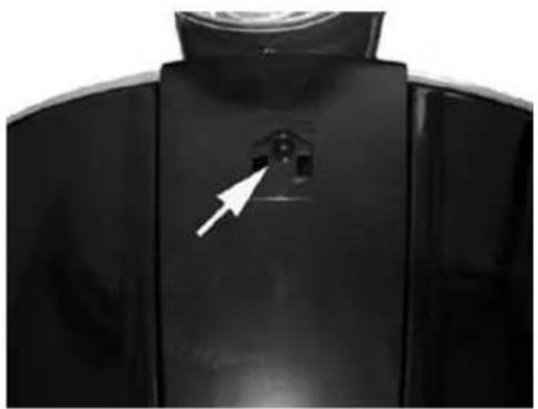
natural_image
Close-up of a black plastic container with a white arrow pointing to a small opening (no text or symbols visible)INDEX OF TOPICS
PRE-DELIVERY
Perform the checks below before delivering the vehicle.
Warning - Be very careful when handling fuel.
Aesthetic inspection
Predelivery checks:
- Paintwork
- Mating of plastics
- Scratches
- Dirt
Tightening torques inspection
- Safety tightening torques
- Cover fixing screws
LOCKS INSPECTION
Name Torque in Nm
| Rear shock absorber top tightening | 20÷ 25 N•m |
| Rear shock absorber bottom tightening | 33÷ 41 N•m |
| Left-hand shock absorber lower support bolts | 20 ÷ 25 |
| Front wheel spindle nut | 75 ÷ 90 |
| Rear wheel spindle nut | 104 ÷ 126 |
| Rear brake disc bolts | 11 ÷ 13 |
| Oscillating arm pin - Chassis | 76 ÷ 83 Nm |
| Oscillating arm pin - Engine | 64 ÷ 72 Nm |
| Handlebar fastening bolt | 45 ÷ 50 Nm |
| Steering upper collar | 30 ÷ 40 |
| Steering lower collar | 8 ÷ 10 |
Electrical system
- Master switch
- Headlights: upper beams, dipped beams, side/taillights (front and rear) and relevant light indicators
- Headlight setting according to the regulations in force
- Front and rear brake light buttons and related lamp
- Direction indicators and related lights
-
Instrument panel lights
-
Instruments. fuel and temperature indicator
- Instrument unit indicator lights
- Horn
- Electric start-up
• Engine stop by emergency stop switch and side stand - Saddle electric opening button
CAUTION
TOBENSUREBMAXIMUMPERFORMANCE,BTHEBBATTERYBMUSTBBEBCHARGEDBBEFOREBUSE.BINADEQUATEBCHARGINGBOFBTHEBBATTERYBBEFOREBITBISBFIRSTBUSEDBWITHBABLOWBLEVELBOFBTHEBELECTROLYTEBSHORTENSBTHEBLIFEBOFBTHEBBATTERY.
CAUTION
WHENBINSTALLINGBTHEBBATTERY,BFIRSTBFIXBTHEBPOSITIVEBCABLEBANDBTHENBTHEBNEGATIVE CABLE.
WARNING
THEBBATTERYBELECTROLYTEBISBPOISONOUSBANDBCAUSESBSEVEREBBURNSBASBITBCONTAINSBSULPHURICBACID.BAVOIDBCONTACTBWITHBTHEBEYES,BTHEBSKINBANDBCLOTHING. INBCASEBOFBCONTACTBWITHBTHEBEYESBORBTHEBSKIN,BRINSEBGENEROUSLYBWITHBWATER FORBABOUTB15BMINUTESBANDBIMMEDIATELYBSEEKBMEDICALBATTENTION. INBCASEBOFBINGESTION,BIMMEDIATELYBDRINKBLARGEBQUANTITIESBOFBWATERBORBVEGET-ABLEBOIL.BIMMEDIATELYBSEEKBMEDICALBATTENTION.
BATTERIESBPRODUCEBEXPLOSIVEBGASES.BKEEPBTHEMBAWAYBFROMBOPENBFLAMES, SPARKSBANDBCIGARETTES.BIFBTHEBBATTERYBISBCHARGEDBINBABCLOSEDBPLACE,BTAKE CAREBTOBENSUREBADEQUATEBVENTILATION.BALWAYSBPROTECTBTHEBEYESBWHENBWORKINGBCLOSEBTOBBATTERIES.
KEEPBOUTBOFBREACHBOFBCHILDREN
CAUTION
NEVERBUSEBFUSESBHAVINGBABHIGHERBRATINGBTHANBRECOMMENDED.BUSINGBABFUSEBOFBUNSUIT-ABLEBRATINGBMAYBSERIOUSLYBDAMAGEBTHEBVEHICLEBORBEVENBCAUSEBABFIRE.
LevelsBcheck
LevelBcheck:
Fuel level in the tank.
Hydraulic braking system fluid level
Rear hub oil level
Engine oil level
Engine coolant level
RoadBtest
Road test:
- Cold starting
- Operation of instruments
- Operation of throttle control
- Stability during acceleration and braking
- Operation of front and rear brakes
- Operation of front and rear suspensions
- Abnormal noise from vehicle
StaticBtest
StaticBinspectionBafterBtestBonBtheBroad
- Hot start
- Starter operation
- Idel speed hold (by turning the handlebar)
• Even steering wheel rotation - Leaks, if any
- Radiator electric fan operation
CAUTION
CHECKBTHEBINFLATINGBPRESSURESBWHENBTHEBTYRESBAREBATBAMBIENTBTEMPERATURE.
CAUTION
NOTBEXCEEDTHEBRECOMMENDEDBINFLATINGBPRESSURESASBTHEBTYRESBMAYBBURST.
FunctionalBinspection
FunctionalBCheck:
• Hydraulic braking system - Lever stroke
- Clutch - Proper performance check
- Engine - General proper performance check and absence of unusual noise
- Miscellaneous: check documents, check chassis and engine no., ancillary tools, number plate assembly, check locks, check tyre pressure, installation of rear-view mirrors and optional fixtures
INDEX OF TOPICS
TIME
This section provides information on the time required to perform fixing operations.
The following information is indicated for every operation: description, code and time required.
Engine
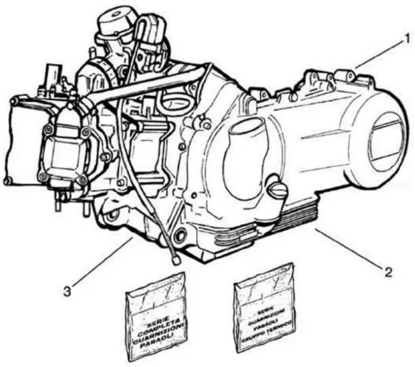
ENGINE
Code Action Duration
| 1 | 001001 | Engine to frame - Disassembly and reassembly |
| 2,003064,Engine oil - Replacement | ||
| 3,003057,Engine attachment - Nuts | tightening | |
Crankcase
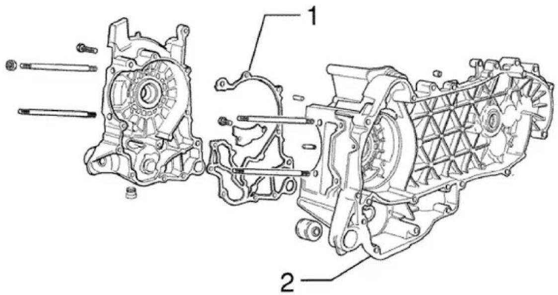
CRANKCASE
Code Action Duration
| 1 | 001153 | Crankcase half gasket - Replacement |
| 2 | 001133 Engine crankcase - Replacement | |
Crankshaft
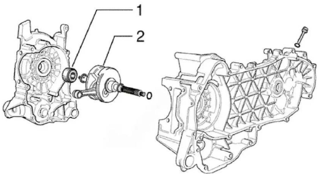
CRANKSHAFT
Code Action Duration
| 1 | 001099 | Clutch-side oil guard - Re- |
Code Action Duration
| placement | ||
| 2 | 001117 | Engine driving shaft - Replacement |
Cylinder assy.
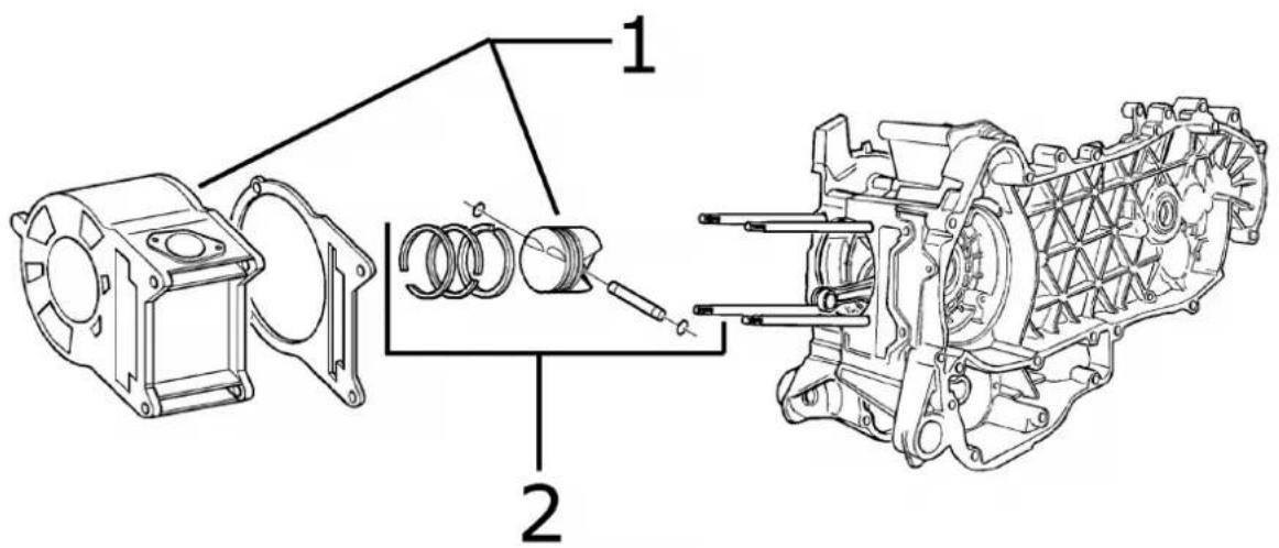
PISTON-CYLINDER
Code Action Duration
| 1 001002 Piston-Cylinder - Replacement | ||
| 2 | 001154 | Pin ring piston unit - Over-haul |
Cylinder head assy.
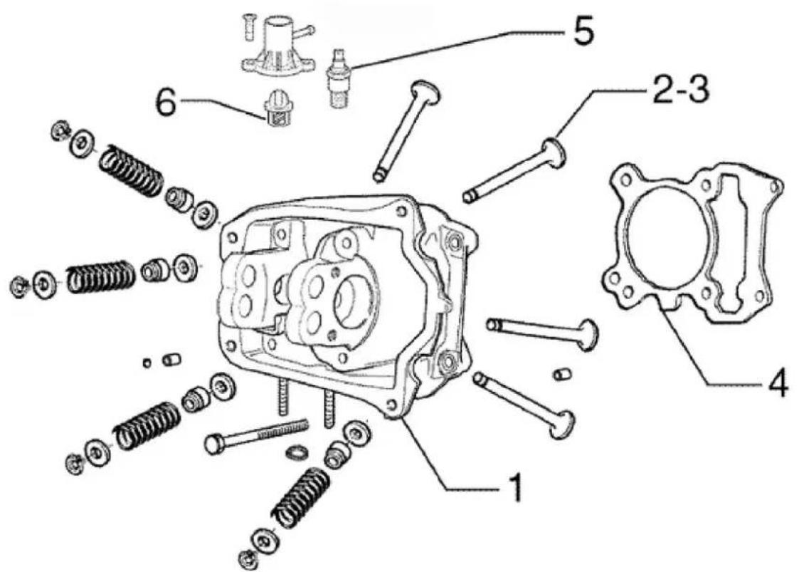
VALVE HEAD
Code Action Duration
| 1 001126 Head - Replacement |
| 2 001045 Valves - Replacement |
| 3 001049 Valves - Adjustment |
| 4 001056 Head gasket - Replacement |
| 5 001083 Thermistor - Replacement |
| 6 001057 Thermostat - Replacement |
Rocker arms support assy.
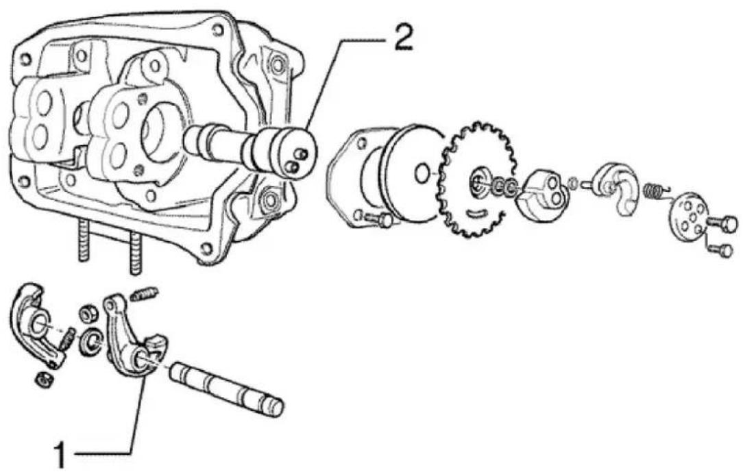
CAMSHAFT
Code Action Duration
1 001148 Valve rockers - Replacement
2 001044 Camshaft - Replacement
Cylinder head cover
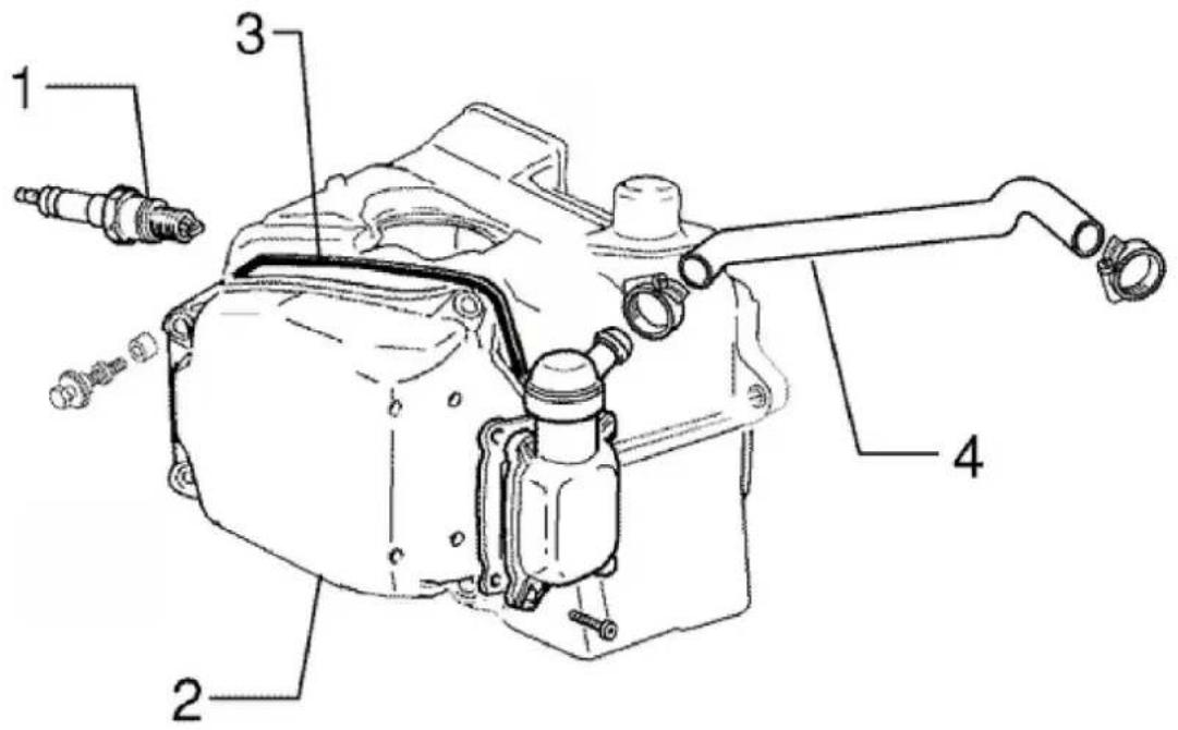
HEAD COVER
Code Action Duration
| 1 001093 Spark plug - Replacement | ||
| 2 001089 Head cover - Replacement | ||
| 3 | 001088 | Head cover gasket - Replacement |
| 4 | 001074 | Oil vapour recovery pipe - Replacement |
Chain tensioner
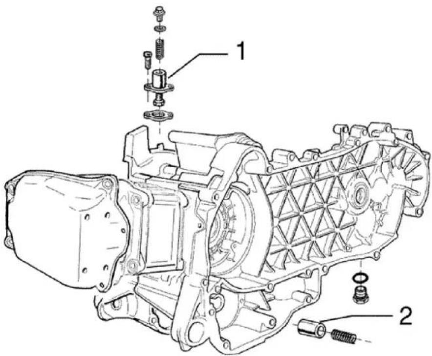
CHAIN TIGHTENER
Code Action Duration
| 1 001129 Chain tightener - Overhaul | and Replacement | |
| 2 | 001124 | Lubrication by pass - Re-placement |
Oil filter
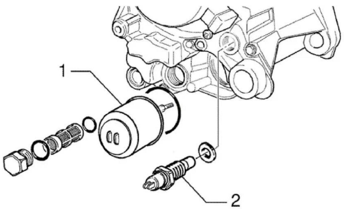
OIL FILTER
Code Action Duration
| 1 001123 Oil filter - Replacement | ||
| 2 | 001160 | Oil pressure sensor - Replacement |
Driven pulley
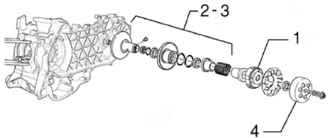
DRIVEN PULLEY
Code Action Duration
| 1 001022 Clutch - Replacement |
| 2 001012 Driven pulley - Overhaul |
| 3 001110 Driver pulley - Replacement |
Code Action Duration
4 001155 Clutch bell - Replacement
Oil pump
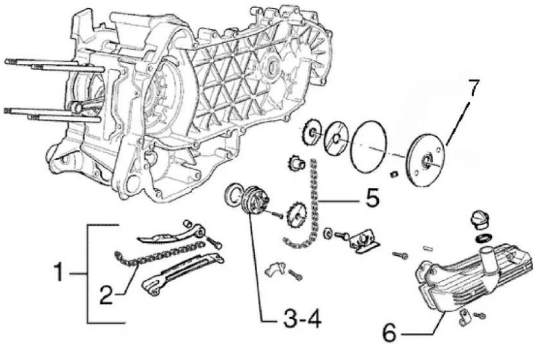
OIL SUMP PUMP
Code Action Duration
| 1 | 001125 | Chain guide pads - Replacement |
| 2 | 001051 Belt/Timing chain - Replacement | ment |
| 3 | 001042 Oil pump - Overhaul | |
| 4 | 001112 Oil pump - Replacement | |
| 5 | 001122 | Oil pump chain - Replacement |
| 6 | 001130 Oil sump - Replacement | |
| 7 | 001172 | Chain cover flap - Replacement |
Final gear assy.
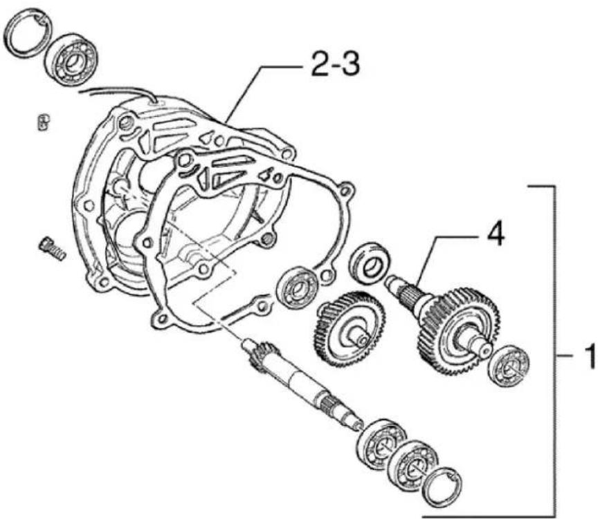
REAR WHEEL AXLE
Code Action Duration
| 1 | 001010 | Geared reduction unit - Replacement |
| 2 003065 Gearcase oil - Replacement | ||
| 3 | 001156 | Geared reduction unit cover - Replacement |
| 4 | 004125 | Rear wheel spindle - Replacement |
Driving pulley
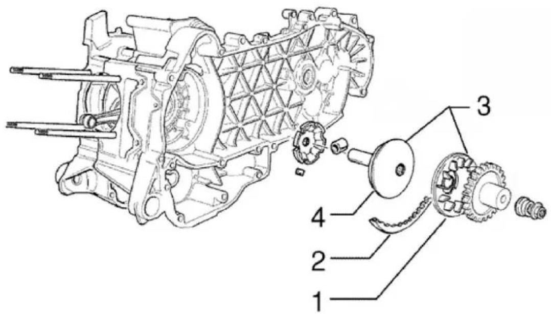
DRIVING PULLEY
Code Action Duration
| 1 001086 Driving half-pulley - Replacement | |
| 2 001011 Driving belt - Replacement | |
| 3 001066 Driving pulley - Disassembly and reassembly | |
| 4 001006 Driving pulley - Overhaul |
Transmission cover
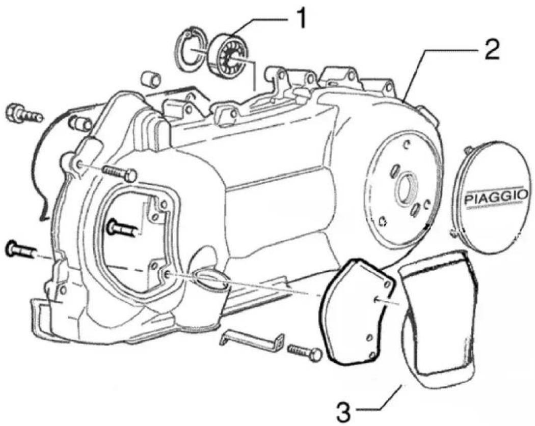
TRANSMISSION COVER
Code Action Duration
| 1 001135 Transmission cover bearing - Replacement | ||
| 2 001096 Transmission casing cover - Replacement | ||
| 3 | 001131 | Transmission air intake - Replacement |
Starter motor
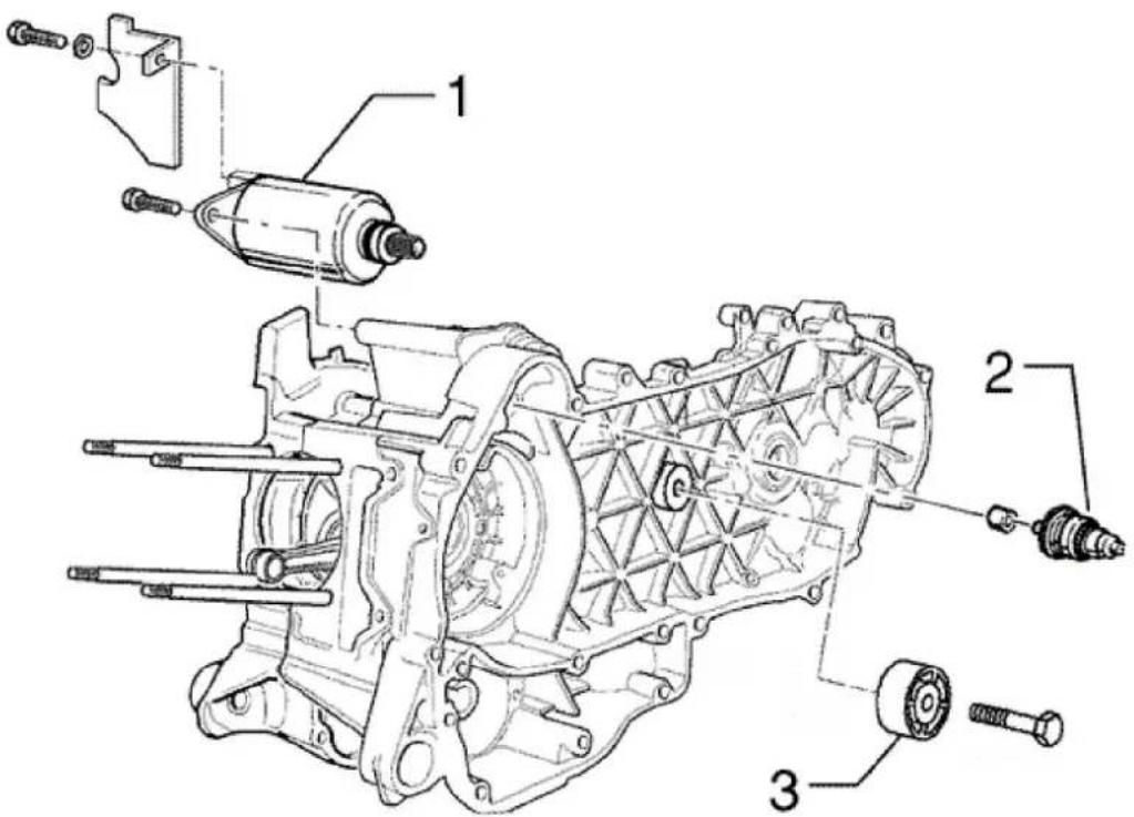
ELECTRIC STARTER
Code Action Duration
| 1 001020 Starter motor - Replacement | ||
| 2 001017 Starter pinion - Replacement | ||
| 3 | 001141 | Belt baffling roller - Replacement |
Flywheel magneto
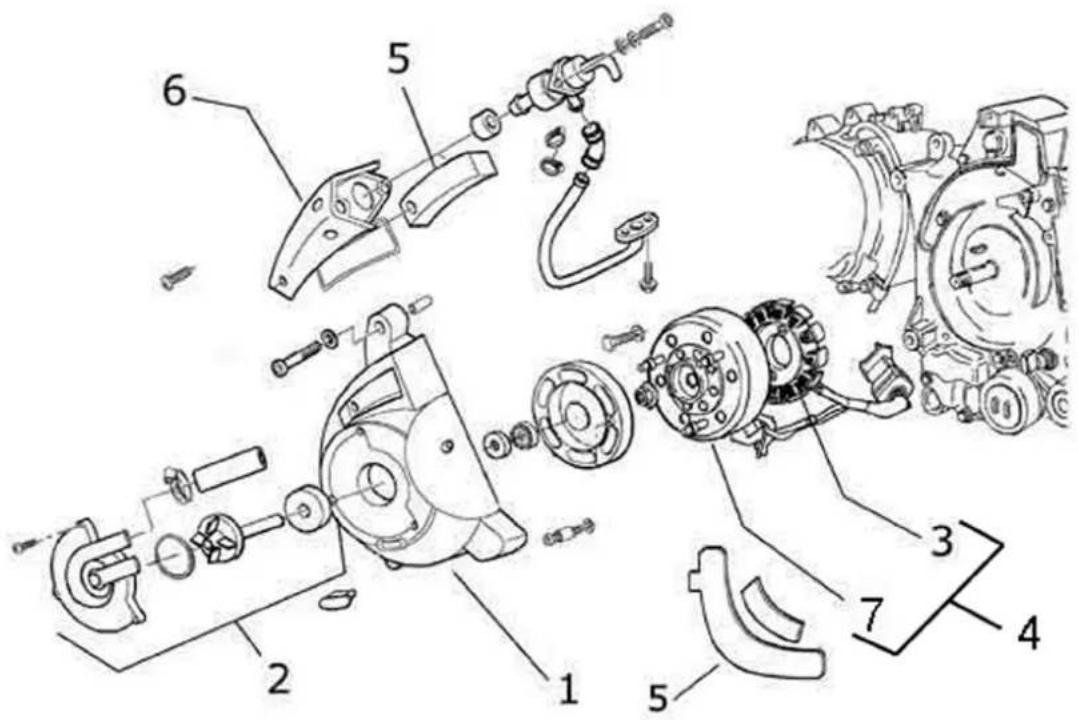
FLYWHEEL MAGNETO
Code Action Duration
| 1 001087 Flywheel cover - Replacement | ||
| 2 001113 Water pump - Replacement | ||
| 3 | 001067 | Stator - Removal and Reassembly |
| 4 001058 Complete flywheel - Replacement | ||
| 5 | 001161 | Secondary air filter - Replacement |
| 6 | 001162 | Secondary air filter box - Replacement |
| 7 001173 Rotor - Replacement | ||
Carburettor
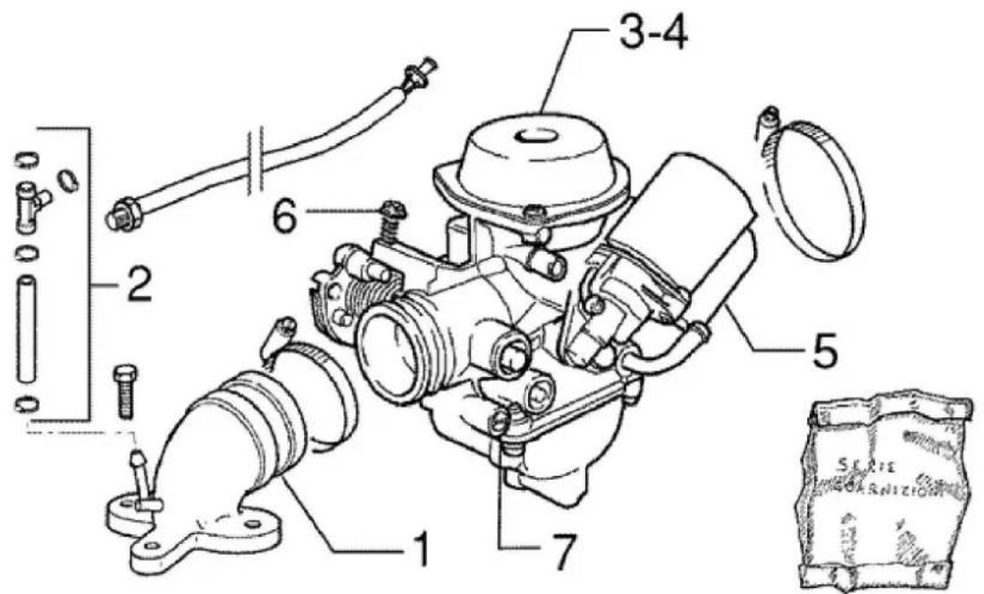
CARBURETTOR
CodeBActionBDuration
| 1 001013 Intake manifold - Replacement | ||
| 2 | 007020 | Fuel heating pipe. - Replacement |
| 3 001008 Carburettor - Overhaul | ||
| 4 001063 Carburettor - Replacement | ||
| 5 001081 Automatic starter device - Replacement | ||
| 6 003058 Carburettor - Adjustment | ||
| 7 001136 Exhaust emissions - Adjustment | ||
ExhaustBpipe
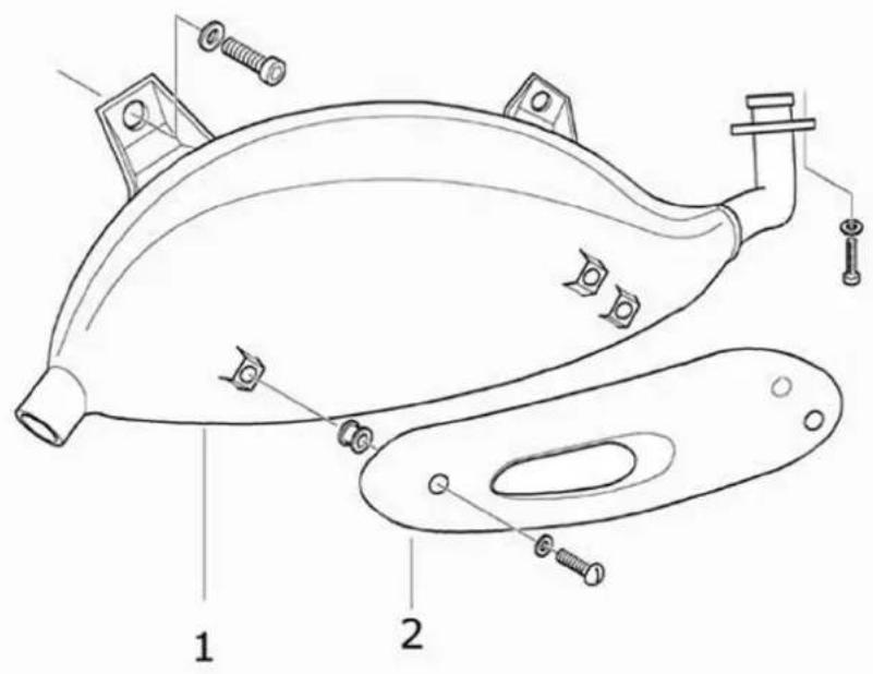
SILENCER
Code Action Duration
| 1 001009 Silencer - Replacement | |
| 2 001095 Silencer guard - Replacement |
Air cleaner
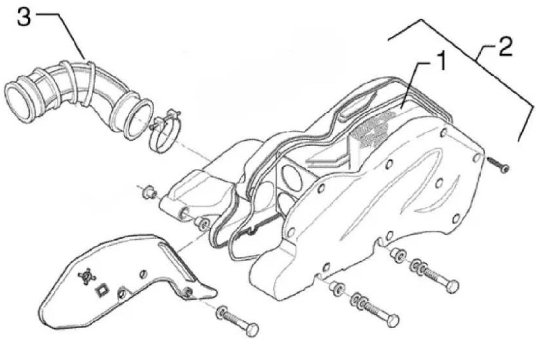
CLEANER
Code Action Duration
| 1 001014 Air Filter - Replacement/Cleaning | ||
| 2 004122 Carburettor cleaner union - Replacement | ||
| 3 | 001015 | Air filter box - Replacement |
Frame
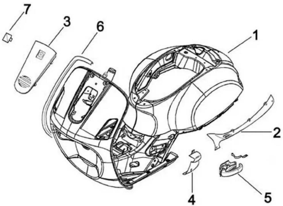
CHASSIS
Code Action Duration
| 1 004001 Chassis - Replacement | ||
| 2 | 004085 | Side panel (1) - Replacement |
| 3 | 004149 | Front shield cover - Replacement |
| 4 004053 Spoiler - Replacement | ||
| 5 004015 Footrest - Disassembly and reassembly | ||
| 6 | 004023 | Front shield beading - Replacement |
| 7 | 004159 | Plates / Stickers - Replacement |
Centre-stand
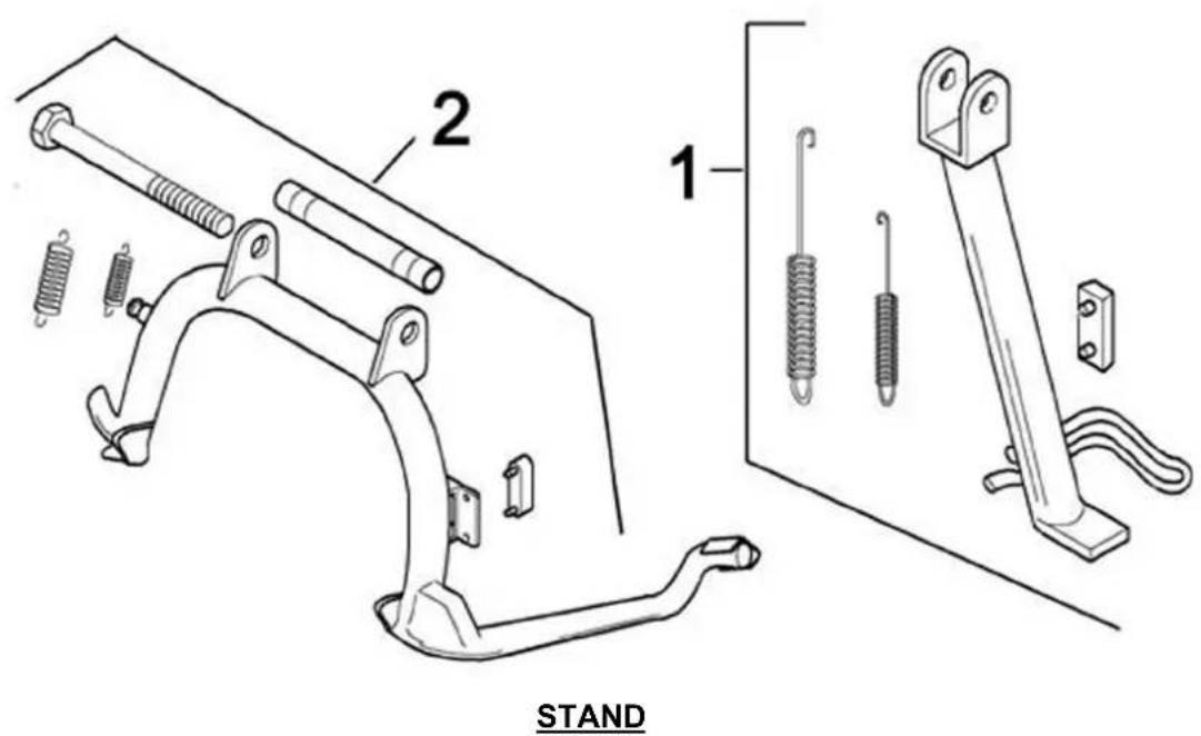
Code Action Duration
1 004102 Side stand - Replacement
2 004004 Stand - Replacement
Footrests
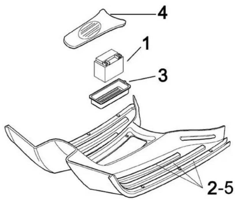
FOOTRESTS
Code Action Duration
| 1 005007 Battery - Replacement | |
| 2 004079 Footboard - Replacement | |
| 3 004071 Battery compartment - Re- | placement |
| 4 005046 Battery cover - Replacement | |
| 5 004078 Front/rear footboard rubber. - | Replacement |
Rear cover
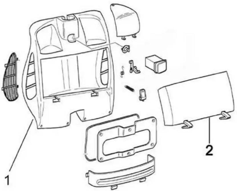
REAR COVER
Code Action Duration
| 1 004083 Glove-box - Replacement | |
| 2 004081 Glove comparment door - Replacement |
Underseat compartment
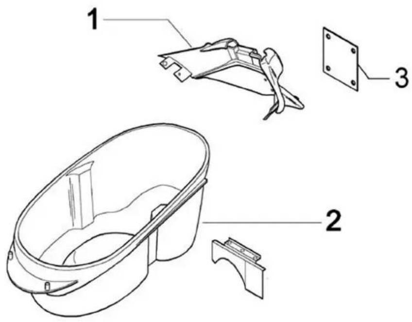
UNDERSEAT COMPARTMENT
Code Action Duration
| 1 | 004136 | License plate holder - Replacement |
| 2 004016 Helmet compartment - Disassembly and reass | ||
| 3 | 005048 | Number plate holder - Replacement |
Mudguard
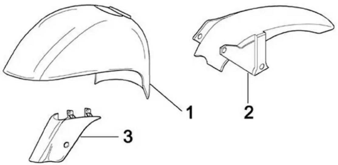
MUDGUARDS
Code Action Duration
| 1 004002 Front mudguard - Replacement | ||
| 2 004009 Rear mudguard - Replacement | ||
| 3 | 003044 | Shock absorber cover - Replacement |
Fuel tank
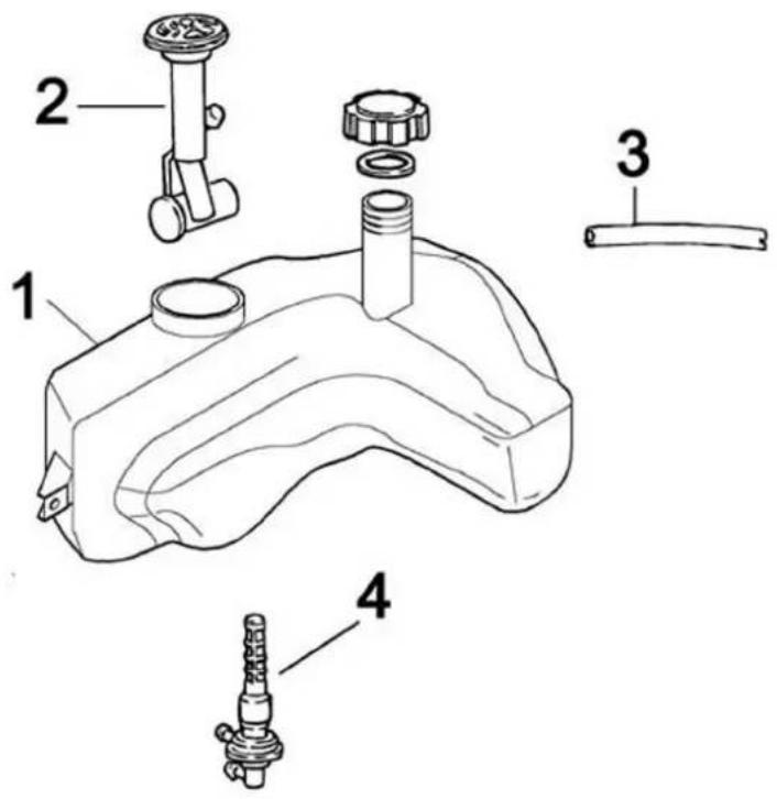
FUEL TANK
Code Action Duration
| 1 004005 Fuel tank - Replacement | ||
| 2 005010 Tank float - Replacement | ||
| 3 | 004109 | Fuel tank breather - Replacement |
| 4 004007 Mixture cock - Replacement | ||
Expansion tank
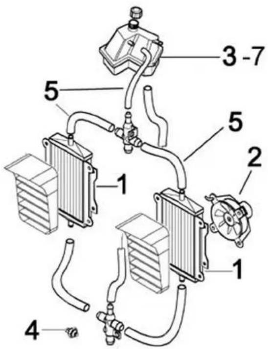
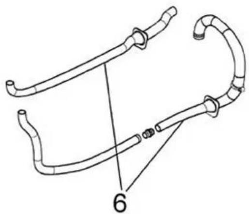
natural_image
Technical line drawing of a mechanical linkage or connector assembly (no text or symbols)EXPANSION TANK
Code Action Duration
| 1 007002 Water radiator - Replacement | ||
| 2 | 007016 | Fan complete with support - Repl. |
| 3 007001 Expansion tank - Replacement | ||
| 4 | 007014 | Radiator thermal switch - Replacement |
| 5 007013 Expansion tank/radiator connection pipe - Replacement | ||
| 6 007003 Coolant delivery and return pipe - Repl. | ||
| 7 | 001052 | Coolant and air vent - Replacement |
Rear shock-absorber
REARBSHOCKBABSORBER
CodeBActionBDuration
1 003007 Rear shock
absorber -
Disassembly
and reas-
sembly
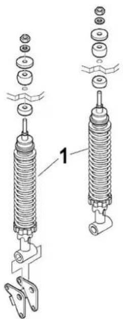
SteeringBcolumnBbearings
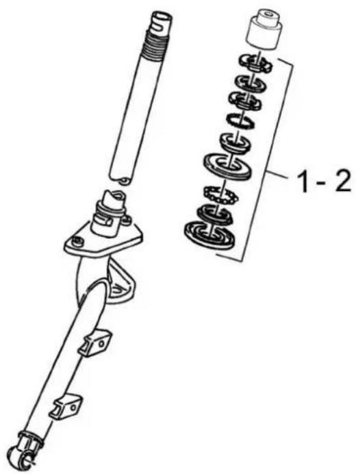
STEERINGBCOLUMNBBEARINGS
CodeBActionBDuration
1
003002
Steering fifth wheels - Re-
CodeBActionBDuration
| placement | |
| 2 003073 Steering play - Adjustment | |
HandlebarBcovers
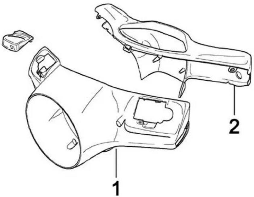
HANDLEBARBCOVERS
| CodeBActionBDuration | ||
| 1 | 004018 | Handlebar front side - Replacement |
| 2 | 004019 | Handlebar rear side - Replacement |
HandlebarBcomponents
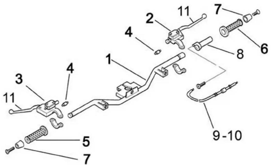
HANDLEBARBCOMPONENTS
CodeBActionBDuration
| 1 003001 Handlebar - Disassembly | and reassembly | |
| 2 | 002024 | Rear brake pump - Replacement |
| 3 | 002024 | Front brake pump - Removal and re-assembly |
| 4 | 005017 | Stop light switch - Replacement |
| 5 | 002059 | Throttle twist grip - Replacement |
| 6 002071 Left knob - Replacement | ||
| 7 003059 Balance weight - Replacement | ||
| 8 002060 Gas control - Replacement | ||
| 9 002063 Gas control transmission - Replacement | ||
| 10 | 003061 | Throttle control cable - Adjustment |
| 11 | 002037 | Complete gas control - Replacement |
Swing-arm
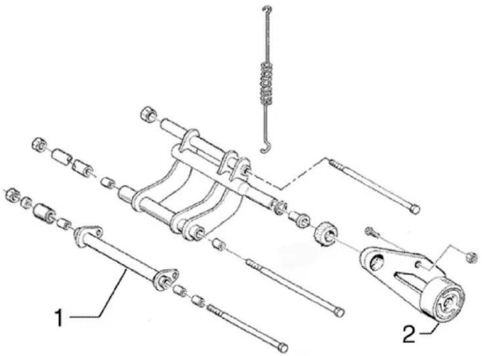
SWINGBARM
CodeBActionBDuration
| 1 001072 Engine-frame connection | swing arm - Replacement |
| 2 004058 Silentbloc - Replacement |
BrakeBhoses
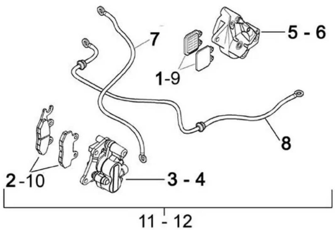
BRAKEBLINEBCALIPER
CodeBActionBDuration
| 1 003071 Rear brake pads/hook - Wear check | ||
| 2 | 003070 | Front brake pads / shoes - Check wear |
| 3 | 002040 | Front brake caliper - Over-haul |
| 4 | 002048 | Rear brake caliper - Replacement |
| 5 | 002068 | Rear brake caliper - Over-haul |
| 6 | 002021 | Front brake line - Removal and refitting |
| 7 | 002020 | Rear brake piping - Removal and reassembly |
| 8 | 002007 | Front brake shoes/pads - Re-moval and refitting |
| 9 | 002002 | Rear brake pads/shoes - Re-moval and reassembly |
| 10 | 002047 | Front brake liquid and circuit bleeding - Replacement |
11 002080 System bleeding and rear
brake oil - Replacement
Seat
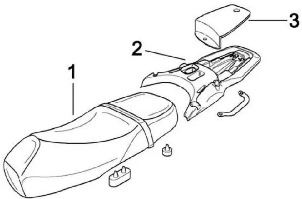
SEAT
Code Action Duration
| 1 | 004136 | License plate holder - Replacement |
| 2 004016 Helmet compartment - Disassembly and reass | ||
| 3 | 005048 | Number plate holder - Replacement |
Instrument panel
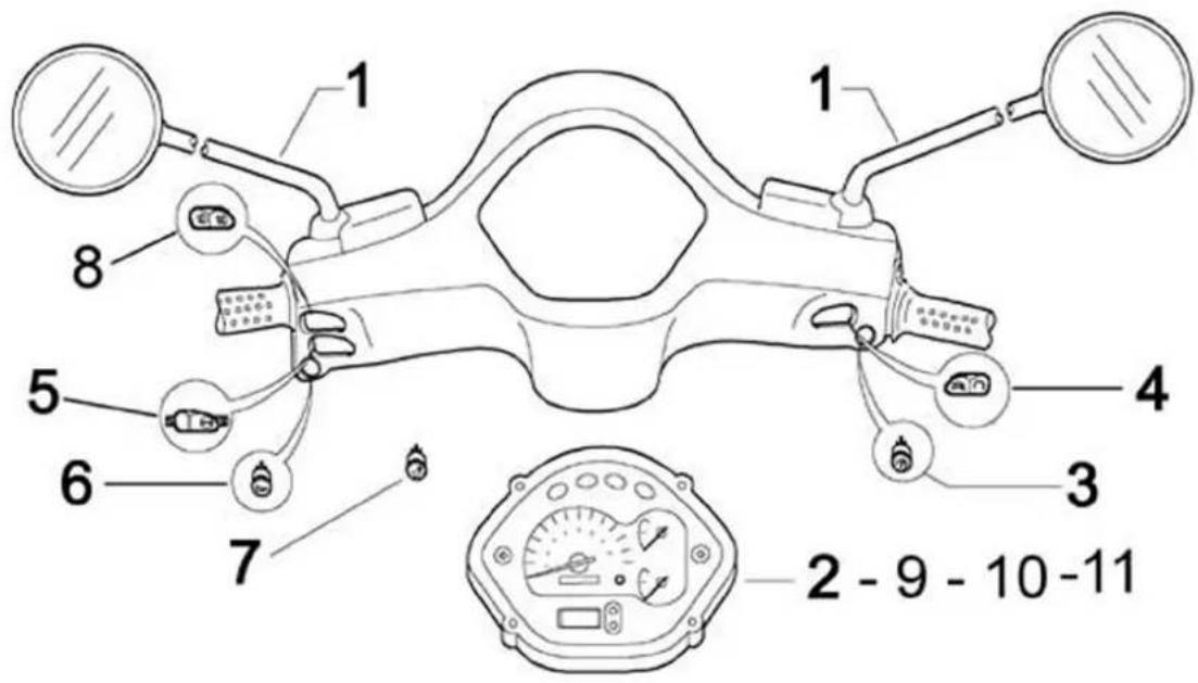
LIGHT GROUP
Code Action Duration
| 1 004066 Rearview mirrors - Replacement | ||
| 2 005014 Odometer - Replacement | ||
| 3 005041 Starter button - Replacement | ||
| 4 005077 Emergency cut-off switch - Replacement | ||
| 5 | 005006 | Lights or flashlights switch - Replacement |
| 6 005040 Horn button - Replacement | ||
| 7 | 005121 | Seat opening button - Replacement |
| 8 005039 Light switch - Replacement | ||
| 9 | 005078 | Odometer plastic cover - Replacement |
| 10 005038 Dashboard warning lights - Replacement | ||
| 11 | 005076 | Clock \ Battery - Replacement |
Locks
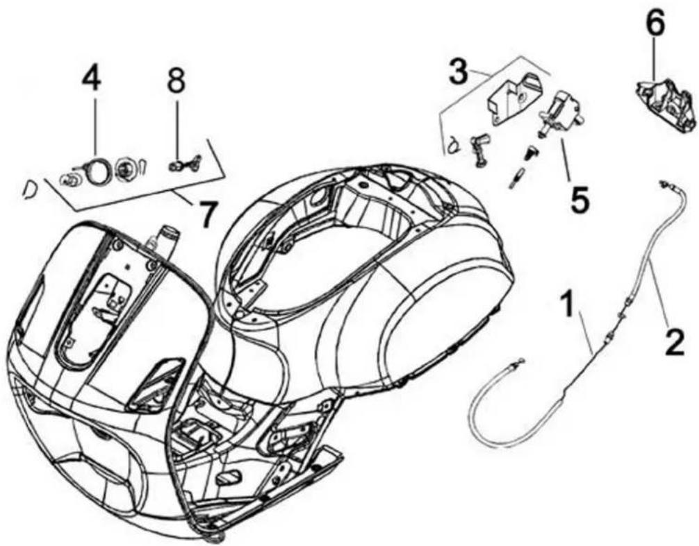
LOCKS
Code Action Duration
| 1 | 002083 | Seat opening cable - Replacement |
| 2 002092 Saddle coupling/splitter | transmission - Repl. | |
| 3 | 004158 | Splitter for saddle opening - Replacement |
| 4 005072 Immobiliser antenna - Replacement | ||
| 5 005099 Saddle electric opening | device - Replacement | |
| 6 004054 Saddle catch - Replacement | ||
| 7 004010 Antitheft lock - Replacement | ||
| 8 005016 Ignition switch - Replacement | ||
Turn signal lights
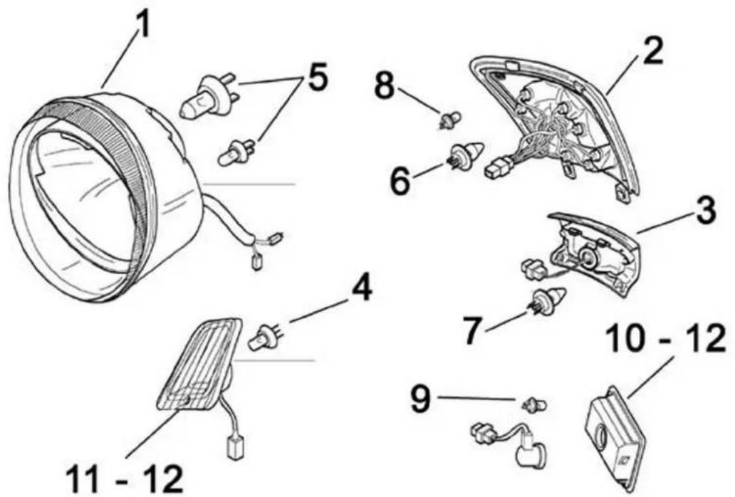
LIGHTS TURN SIGNAL LIGHTS
Code Action Duration
| 1 005002 Headlight - Replacement | ||
| 2 005005 Rear light - Replacement | ||
| 3 | 005032 | Number plate light cover - Replacement |
| 4 005067 Front direction indicator bulb | - Replacement | |
| 5 005008 Front headlights - Replacement | ||
| 6 | 005066 | Rear light bulbs - Replacement |
| 7 | 005031 | Number plate light bulb - Replacement |
| 8 | 005090 | Brake light bulbs - Replacement |
| 9 | 005068 | Rear turn indicator bulb - Replacement |
| 10 | 005022 | Rear turn signal light - Replacement |
| 11 | 005012 | Front turn signal light - Replacement |
| 12 005091 Direction indicators plastic | ||
Code Action Duration
cover - Replacement
Front wheel
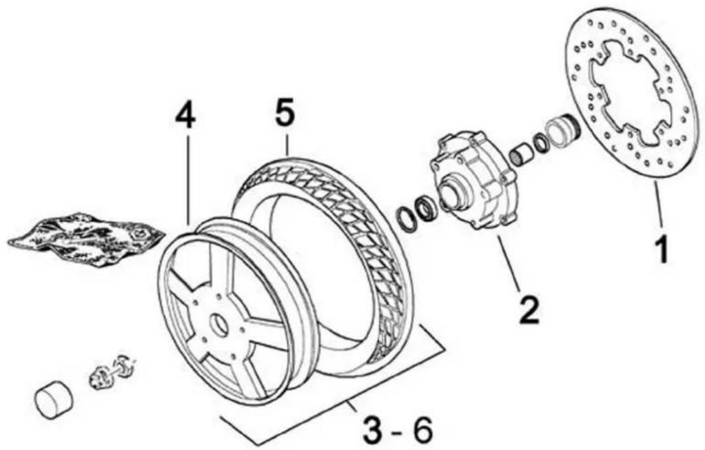
FRONT WHEEL
Code Action Duration
| 1 002041 Brake disc - Replacement | ||
| 2 | 003033 | Front wheel hub - Replacement |
| 3 004123 Front wheel - Replacement | ||
| 4 | 003037 | Front wheel rim - Replacement |
| 5 003047 Front tyre - Replacement | ||
| 6 003063 Tyre pressure - Check | ||
Encoder/speedometer transmission greasing
Please take note that the code has been introduced:
900001 - encoder/speedometer transmission greasing - 15'.
It is recommended not to use erroneously the codes 002011 (speedometer transmission re-
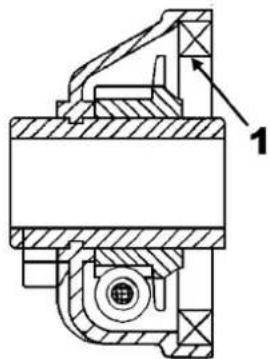
placement) and 005089 (encoder replacement) in the event of noise of the indicated components. The grease recommended is TUTELA MRM 2 (molybdenum bisulphide grease and lithium soap).
The following is to show, by means of an arrow, the area that has to be increased (1 - Speedometer transmission, 2 - Encoder).
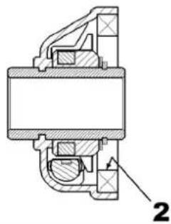
natural_image
Cross-sectional technical drawing of a mechanical assembly (no visible text or labels)Rear wheel
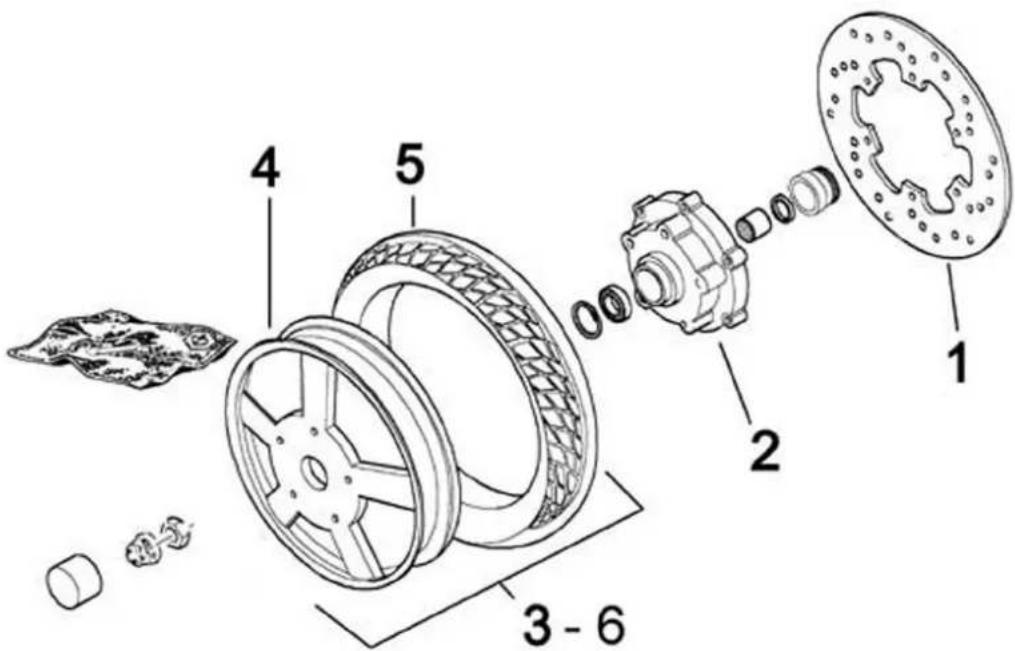
REAR WHEEL
Code Action Duration
| 1,001016,Rear wheel - Replacement | ||
| 2,004126,Rear tyre - Replacement | ||
| 3 | 001071 | Rear wheel rim - Disassembly and reassembly |
| 4 | 002070 | Rear disc brake - Replacement |
| 5,003077,Silencer/rear shock absorbersupport arm - Overhaul | ||
| 6 | 002028 | Rear wheel hub - Replacement |
Code Action Duration
7 003063 Tyre pressure - Check
Fuel pump
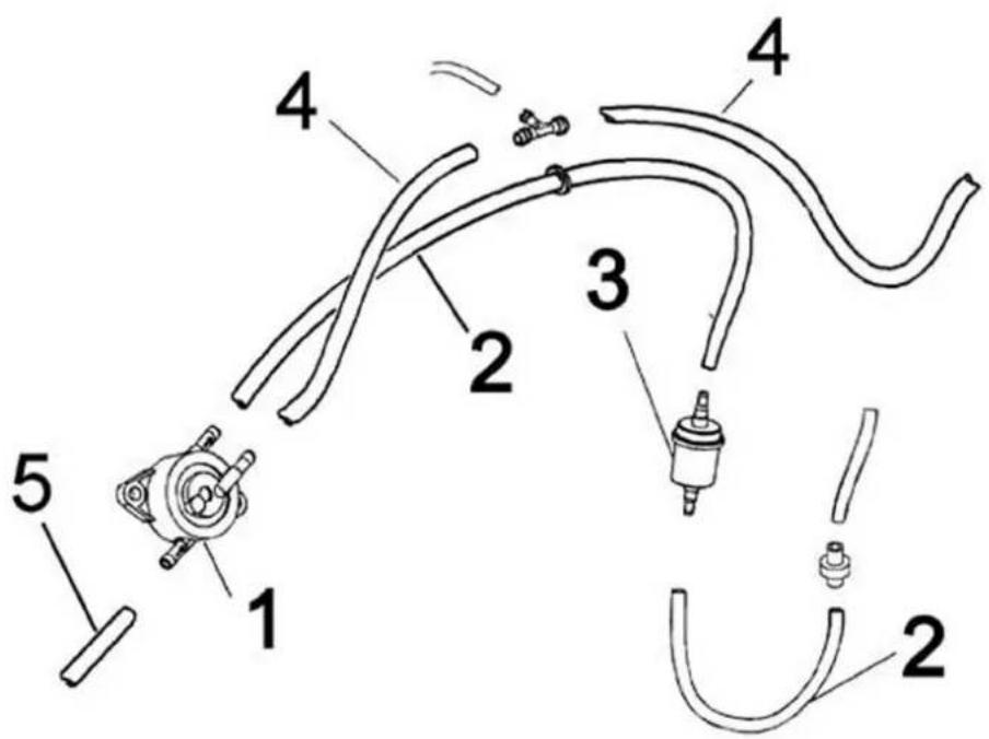
FUEL PUMP
Code Action Duration
| 1 004073 Fuel pump - Replacement | ||
| 2 | 004089 | Fuel tank/pump tube - Replacement |
| 3 004072 Fuel filter - Replacement | ||
| 4 | 004086 | Fuel pump vacuum pipe - Replacement |
| 5 004086 Injector/carburettor-pump | pipe - Replacement | |
Electric devices
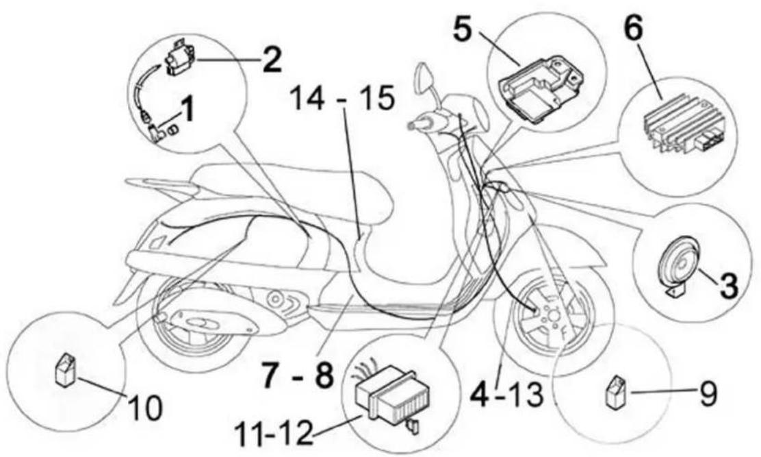
ELECTRIC DEVICES
Code Action Duration
| 1 | 001094 | Spark plug cap - Replacement |
| 2 | 001069 H.T. coil - Replacement | |
| 3 | 005003 Electric horn - Replacement | |
| 4 | 002049 Odometer cable - Replacement | |
| 5 | 001023 Controller - Replacement | |
| 6 | 005009 Voltage regulator - Replacement | |
| 7 | 005001 Electric system - Removal and reassembly | |
| 8 | 005114 Electric circuit - Overhaul | |
| 9 | 005035 Headlight relay - Replacement | |
| 10 | 005011 Start-up remote control switch - Replacement | |
| 11 | 005054 Fuse holders - Replacement | |
| 12 | 005019 Fuse carrier - Replacement | |
| 13 | 002051 Odometer transmissions assembly - Replacement | |
| 14 | 005024 Battery fuse - Replacement | |
| 15 | 002025 Brake hose - Replacement |
Front suspension
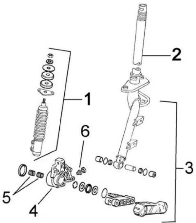
FRONT SUSPENSION
Code Action Duration
| 1 | 003011 | Front shock absorber - Re-moval and refitting |
| 2 003045 Steering column - Replacement | ||
| 3 003010 Front suspension - Overhaul | ||
| 4 | 003035 | Shock abs. and brake caliper support - Replacement |
| 5 | 003034 | Front wheel hub bearings - Replacement |
| 6 001064 Speedometer gear - Replacement | ||