X3-FTH - Punjač baterija SolaX Power - Besplatni korisnički priručnik
Pronađite besplatno priručnik za uređaj X3-FTH SolaX Power u PDF formatu.

Pitanja korisnika o X3-FTH SolaX Power
0 pitanje o ovom uređaju. Odgovorite na one koje znate ili postavite svoje.
Postavi novo pitanje o ovom uređaju
Preuzmite upute za vaš Punjač baterija u PDF formatu besplatno! Pronađite svoj priručnik X3-FTH - SolaX Power i uzmite svoju elektroničku napravu natrag u ruke. Na ovoj stranici objavljeni su svi dokumenti potrebni za korištenje vaše naprave. X3-FTH marke SolaX Power.
KORISNIČKI PRIRUČNIK X3-FTH SolaX Power

SOLAX POWER
X3-FORTH SERIES USER MANUAL
40kW - 150kW
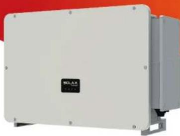
natural_image
Exterior view of a white industrial electrical enclosure with a black logo and mounting brackets (no readable text or symbols)
SOLAX POWER
EN
SolaX Power Network Technology (Zhejiang) Co., Ltd.
No.288,Shizhu Road, Tonglu Economic Development Zone, Tonglu City, Zhejiang
Province, 310000 P. R. CHINA
Tel: +86 (0) 571-5626 0011
E-mail: info@solaxpower.com
320101031208
Copyright Declaration
The copyright of this manual belongs to SolaX Power Network Technology (Zhejiang) Co., Ltd. Any corporation or individual should not plagiarize, partially or fully copy (including software, etc.), and no reproduction or distribution of it in any form or by any means. All rights reserved. SolaX Power Network Technology (Zhejiang) Co., Ltd. reserves the right of final interpretation.
www.solaxpower.com
CHANGE HISTORY
Changes between document versions are cumulative. The latest version contains all updates made in previous versions.
Version 08 (Jul. 18, 2023)
Added local MODBUS parallel function description
Modified Troubleshooting
Added OT terminal instructions
Version 07 (Apr. 19, 2023)
Added the data of 75kW, 100kW 12 MPPT and 110kW 12 MPPT
Version 06 (Feb. 15, 2023)
Added Change History
Updated 2.3 Explanation of Symbols (Modified the explanations of the symbols)
Updated diagram of PLC connection
Updated 4 Technical Data (Modified and added new items)
Version 05 (Sep. 12, 2022)
Modified the neutral version
Added a diagram to PLC Box connection
Updated USB
Version 04 (Mar. 15, 2022)
Uadded information of the screen version
Version 03 (Nov. 26, 2021)
Modified the layout of the contents, technical data and schematic diagram
Version 02 (Nov. 26, 2021)
Added low voltage and all related contents
Version 01 (Oct. 23, 2021)
Added The communication line is changed to 30 cores
Version 00 (Sep. 25, 2021)
Initial release
Contents
CONTENTS
1 NOTE ON THIS MANUAL 03
1.1 SCOPE OF VALIDITY 03
1.2 TARGET GROUP 03
1.3 SYMBOLS USED 03
2 SAFETY 04
2.1 APPROPRIATE USAGE 04
2.2 IMPORTANT SAFETY INSTRUCTIONS....05
2.3 EXPLANATION OF SYMBOLS 08
2.4 EC DIRECTIVES....09
3 INTRODUCTION....10
3.1 PHOTOVOLTAIC GRID CONNECTED SYSTEM....10
3.2 BASIC FEATURES 12
3.3 OVERVIEW OF THE INVERTER 12
3.4 DIMENSION 13
3.5 PRINCIPLE DESCRIPTION 14
4 TECHNICAL DATA 16
4.1 DC INPUT 16
4.2 AC OUTPUT 17
4.3 EFFICIENCY, SAFETY AND PROTECTION....18
4.4 GENERAL DATA 19
5 MECHANICAL INSTALLATION 20
5.1 INSTALLATION PRECAUTION....20
5.2 SELECTION FOR THE INSTALLATION POSITION 20
5.2.1 INSTALLATION ENVIRONMENT REQUIRED....21
5.2.2 INSTALLATION CARRIER REQUIRED....21
5.2.3 INSTALLATION ANGLE REQUIRED....22
5.2.4 INSTALLATION SPACE REQUIRED 23
5.3 TOOLS PREPARATION 24
5.4 CHECK FOR TRANSPORT DAMAGE 25
5.5 PACKING LISTS 25
Contents
Notes on this Manual
5.6 INSTALLATION STEPS 26
5.6.1 INSTALLATION STEPS (ON THE WALL) 26
5.6.2 INSTALLATION STEPS (ON THE STAND) 27
6 ELECTRICAL CONNECTION 29
6.1 GROUNDING CONNECTION 29
6.2 PV STRING CONNECTION 30
6.3 GRID CONNECTION 33
6.4 COMMUNICATION CONNECTION....38
6.4.1 COMMUNICATION SIGNAL DEFINITION 38
6.4.2 CONNECTION STEPS OF CABLE 39
6.4.3 RELEASE STEPS OF CABLE 40
6.5 PARALLEL CONNECTION 40
6.5.1 DATAHUB PARALLEL CONNECTION....41
6.5.2 MODBUS PARALLEL CONNECTION 42
6.6 PLC BOX CONNECTION (OPTIONAL) 43
6.7 CONTROL OUTPUT POWER BY CONNECTING A RRCR.....44
6.8 MONITORING CONNECTION 45
7 STARTUP OF INVERTER....48
8 FIRMWARE UPGRADING 51
9 SETTING 53
10 TROUBLESHOOTING....65
10.1 TROUBLESHOOTING....65
10.2 ROUTINE MAINTENANCE 72
11 DECOMMISSIONING....74
11.1 DISMANTLING THE INVERTER....74
11.2 PACKAGING 74
11.3 STORAGE AND TRANSPORTATION 74
11.4 DISPOSING OF THE INVERTER....74
12 DISCLAIMER 75
* WARRANTY REGISTRATION FORM
1 Notes on this Manual
1.1 Scope of Validity
This manual is an integral part of X3-FORTH series. It describes the assembly, installation, commissioning, maintenance, and failure of the product. Read it carefully before operating.
| X3-FTH-40K-LV | X3-FTH-50K-LV | X3-FTH-60K-LV | X3-FTH-70K-LV |
| X3-FTH-75K | X3-FTH-80K | X3-FTH-100K | X3-FTH-110K |
| X3-FTH-125KX3-FTH31FTH-136K-MV | X3-FTH-150K-MV | ||
Note: "X3": means three phases, "FTH" means FORTH, "80K" means 80 kW. Each model is available with LED indicator lights and LCD.
40kW/50kW/60kW/70kW inverters work in the 127V/220V low voltage range. 75kW/80kW/100kW/110kW/120kW/125kW inverters work in the 220V/380V voltage range. 136kW/150kW inverters work in the 500V/540V medium voltage range.
Keep this manual in a place where it is accessible all the time.
1.2 Target Group
This manual is for qualified electricians. The tasks described in this manual only can be performed by qualified electricians.
1.3 Symbols Used
The following types of safety instructions and general information appear in this document as described below:

DANGER!
"Danger" indicates a hazardous situation which, if not avoided, will result in death or serious injury.

WARNING!
"Warning" indicates a hazardous situation which, if not avoided, could result in death or serious injury.

CAUTION:
"Caution" indicates a hazardous situation which, if not avoided, could result in a minor or moderate injury.

NOTE!
"Note" provides tips that are valuable for the optimal operation of your product.
2 Safety
2.1 Appropriate Usage
The inverters are PV inverters which can convert the DC current of the PV generator into AC current and feed it into the public grid.
Surge protection devices (SPDs) for PV installation

WARNING!
Over-voltage protection with surge arresters should be provided when the PV power system is installed. The grid connected inverter is fitted with SPDs in MAINS side.
Induced surges are the more likely cause of lightning damage in the majority of installations, especially in rural areas where electricity is usually provided by long overhead lines. Surges may be induced on both the PV array conductors or the AC cables leading to the building.
Specialists in lightning protection should be consulted in the actual application. Using appropriate external lightning protection, the effect of a direct lightning strike into a building can be mitigated in a controlled way, and the lightning current can be discharged into the ground.
Installation of SPDs to protect the inverter against mechanical damage and excessive stress includes a surge arrester in the case of a building with external lightning protection system (LPS) when separation distance is kept.
To protect the DC system, surge protection device (SPD type 2) should be fitted at the inverter end of the DC cabling and at the array located between the inverter and the PV generator, if the voltage protection level (VP) of the surge arresters is greater than 1100V, an additional SPD type 2 is required for surge protection for electrical devices.
To protect the AC system, surge protection devices (SPD type 2) should be fitted at the main incoming point of AC supply (at the consumer's cutout), located between the inverter and the meter / distribution system; SPD (test impulse D1) for signal line according to EN 61632-1.
Spark gap protection devices are not suitable to be used in DC circuits once conducting, they won't stop conducting until the voltage passes through their terminals typically less than 30 volts.
Safety Safety
- Anti-Islanding Effect
Islanding effect is a special phenomenon that grid-connected PV system still supplies power to the nearby grid when electrical grid power is no longer present. It is dangerous for maintenance personnel and the public.
The inverter provides Active Frequency Drift (AFD) to prevent islanding effect.
2.2 Important Safety Instructions

DANGER!
Danger to life due to high voltages in the inverter!
- All work must be carried out by qualified electrician.
• The appliance is not to be used by children or persons with reduced physical sensory or mental capabilities, or lack of experience and knowledge, unless they have been given supervision or instruction.
• Children should be supervised to ensure that they do not play with the appliance.

CAUTION!
- Danger of burn injuries due to hot enclosure parts!
- During operation, the upper lid of the enclosure and the enclosure body may become hot.
- Only touch the lower enclosure lid during operation.

CAUTION!
• Possible damage to health as a result of the effects of radiation!
- Do not stay closer than 20 cm to inverter for any length of time.

NOTE!
Grounding the PV generator.
- Comply with the local requirements for grounding the PV modules and the PV generator. We recommend connecting the generator frame and other electrically conductive surfaces in a manner which ensures continuous conduction and ground these in order to have optimal protection of system and persons.
Safety Safety

WARNING!
- Ensure input DC voltage ≤ Max: DC voltage. Over voltage may cause permanent damage to inverter or other losses, which will not be included in warranty!

WARNING!
- Authorized service personnel must disconnect both AC and DC power from the inverter before attempting any maintenance or cleaning or working on any circuits connected to the inverter.

WARNING!
Do not operate the inverter when the device is running.

WARNING!
Risk of electric shock!
- Prior to the application, please read this section carefully to ensure correct and safe application. Please keep the user manual properly stored.
- Use only attachments recommended. Otherwise may result in a risk of fire, electric shock, or injury to a person.
- Make sure that existing wiring is in good condition and that wire is not undersized.
- Do not disassemble any parts of inverter that are not mentioned in installation guide. It contains no user-serviceable parts. See Warranty for instructions on obtaining service. Attempting to service the inverter yourself may result in a risk of electric shock or fire and will void your warranty.
- Keep away from flammable, explosive materials to avoid a fire disaster.
- The installation place should be away from humid or corrosive substances.
- Authorized service personnel must use insulated tools when installing or working with this equipment.
• PV modules shall have an IEC 61730 Class A rating. - Never touch either the positive or negative pole of PV connecting device.
Strictly prohibit touching both of them at the same time. - The unit contains capacitors that remain charged to a potentially lethal voltage after the MAINS and PV supplies have been disconnected.

WARNING!
Hazardous voltage will present for up to 5 minutes after disconnection from power supply.
- CAUTION-RISK of electric shock from energy stored in capacitor. Never operate on the solar connectors, the MAINS cables, PV cables or the PV generator when power is applied. After switching off the PV and MAINs, always wait 5 minutes to let the intermediate circuit capacitors discharge before you unplug DC and MAINS connectors.
- Strictly prohibit the dismantling. Even in the unlikely event that you have to dismantle the machine, you must not touch any internal parts.
PE Connection and Leakage Current
- The inverter incorporates a certified internal Residual Current Device (RCD) in order to protect against possible electrocution and fire hazards in case of a malfunction in the cables or the inverter. There are two-trip thresholds for the RCD as required for certification (IEC 62109-2: 2011).
• The default value for electrocution protection is 30 mA, and for slow rising current is 300 mA.
• If an external RCD is required by local regulations, check which type of RCD is required for relevant electric code. It recommends using a type-A RCD. The recommended RCD value is 300 mA unless a lower value is required by the specific local electric codes. When required by local regulations, the use of an RCD type B is permitted.
The device is intended to connect to a PV generator with a capacitance limit of approx 700 nF.

WARNING!
• High leakage current!
*Earth connection essential before connecting supply.
- Incorrect grounding can cause physical injury, death, or equipment malfunction and increase electromagnetic.
- Make sure that grounding conductor is adequately sized as required by safety regulations.
- Do not connect the ground terminals of the unit in series in case of a multiple installation. This product can cause current with a DC component. For the United Kingdom
- The installation that connects the equipment to the supply terminals comply with the requirements of 767L.shall BS
• The Electrical installation of system shall comply with requirements of PV and 60364-7-712.BS IEC 7671
Safety Safety
- No protection settings can be altered without authorization.
- The installer shall ensure that equipment is installed and operated to at all times in compliance with the requirements of 22 maintain ESQCR (1) (e).
For Australia and New Zealand
- Electrical installation and maintenance shall be conducted by licensed electrician and shall comply with Australia National Wiring Rules.
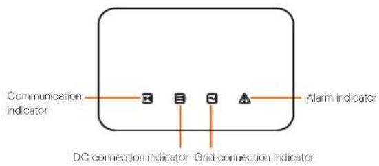
2.3 Explanation of Symbols
This section gives an explanation of all the symbols shown on the inverter and on the type label.
- Symbols on the Inverter
| Symbol | Explanation |
| Communication indicator | |
| DC connection indicator | |
| Grid connection indicator | |
| Alarm indicator |
- Symbols on the Type Label
| Symbol | Explanation |
| CE | CE mark.The inverter complies with the requirements of the applicable CE guidelines. |
| TUV certificated | |
| RCM remark | |
| UKCA | UKCA mark.The inverter complies with the requirements of the applicable UKCA guidelines. |
| Beware of hot surface.The inverter can become hot during operation. Avoid contact during operation. |
| Danger of high voltages.Danger to life due to high voltages in the inverter! | |
| Danger.Risk of electric shock! | |
| Observe enclosed documentation. | |
| The inverter can not be disposed together with the household was Disposal information can be found in the enclosed documentation. | |
| Do not operate this inverter until it is isolated from mains and on-site PV generation suppliers. | |
| Danger to life due to high voltage.There is residual voltage in the inverter which needs 5 minutes to discharge.Wait 5 minutes before you open the upper lid or the DC lid. |
Note: The label is only used for the description of symbols which may be used on the inventor. Please be subject to the actual symbols on the device.
Introduction Introduction
3. Introduction
3.1 Photovoltaic Grid Connected System
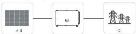
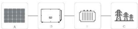
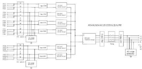
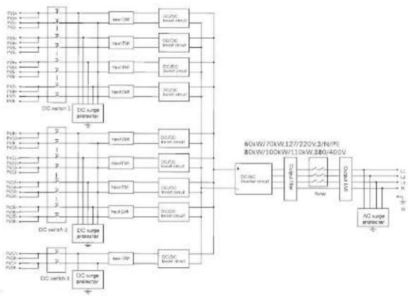
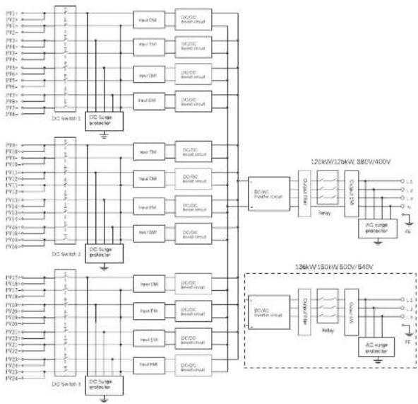
The inverter is a three-phase transformerless grid-connected inverter. It is an important part of photovoltaic power generation system. It converts the direct current generated by the photovoltaic panel into alternating current and also can be used to optimize self-consumption or feed into the public grid. The first figure shows the typical application scenario of 40 kW-125 kW inverter, and the second figure shows the typical application scenario of 136 kW-150 kW inverter.
flowchart
graph LR
    A["Grid A B"] --> B["Unit"]
    B --> C["Power Tower C"]
flowchart
graph LR
    A["A"] --> D["D"]
    D --> E["E"]
    E --> C["C"]
| NO. | Definition |
| A Photovoltaic string | |
| B | X3-FORTH 40 kW-125 kW inverter |
| C | Power grid |
| D | X3-FORTH 136 kW-150 kW inverter |
| E | Transformer |

Warning!
The inverter shall not be connected to the PV string requiring positive grounding or negative grounding. Do not connect local load between inverter and AC side circuit breaker!
The power grids supported by the inverter are TN-S, TN-C, TN-C-S, TT and IT.
40 kW-70 kW inverters are connected to 127 V / 220 V three-phase four wire power grid and 75 kW-125 kW inverters are connected to 380 V / 400 V three-phase four wire power grid, which can be connected with N line (or not), as shown in Figure 1;
136 kW and 150 kW models are directly connected to the medium voltage power grid through a 500 V or 540 V transformer without an N line access, as shown in Figure 2;
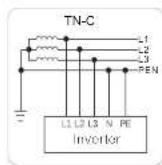
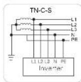
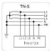
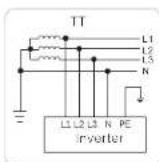
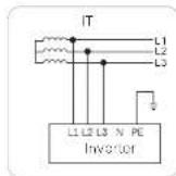
Figure 1
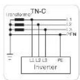
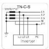
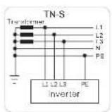
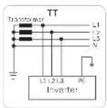
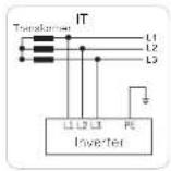
Figure 2
Introduction Introduction
3.2 Basic Features
Thanks for your purchase of this series inverter. Basic features are as follows:
More energy harvest
Maximum efficiency up to 99%
- 180\~1000Vdc MPPT voltage range
- Maximum 12 MPPTs, 2 strings per MPP tracker
- 150% PV oversizing input, 110% overloading output
- Maximum 32A MPPT current
Safety and Reliability
- IP66 protection level
- AFCI protection (optional)
- AC terminal temperature detection
- Both AC and DC SPDs (Type 2) inside, Type 1 + 2 SPD is optional
Intelligence for easy maintenance and economy
- Built-in export power control
- Remote setting and upgrading
• 24 hours operation monitoring
• Smart I-V Curve Diagnosis supported - Night-time reactive power compensation
- Aluminium AC cable connection available
• Power line communication (PLC) (optional) - Fuse free design with smart string current monitoring
- Smart air cooling technique results in long lifetime of fans
- Advanced heat dissipation technology makes the system more than 5% lighter
and smaller
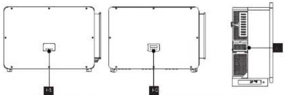
3.3 Overview of the Inverter
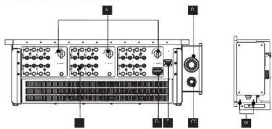
| Item | Description |
| A DC Switch | |
| B | AC Connector |
| C | DC Connector |
| D | RS 485 / Motor / DRM connector (optional) |
| E | WiFi / LAN / 40 dongle connector (optional) |
| F | Ground Connector |
| G | Ground Screw |
| H1 | LED Indicator |
| H2 | LCD (Optional) |
| I | Fan support (cooling fan inside) |

WARNING!
Only authorized personnel is allowed to set the connection.
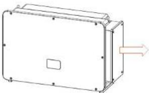
3.4 Dimension
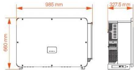

NOTE!
The dimension of the inverter with LCD is same as the inverter with LED.
Introduction
Introduction
3.5 Principle Description
The inverter is equipped with multi-channel MPPT for DC input to ensure maximum power even under different photovoltaic input conditions. The inverter unit converts DC into AC that meets the requirements of the power grid and feeds it into the power grid. The lightning arrester at AC / DC sides can realize the function of surge protection.
The principle design of an inverter is shown in the figure below:
flowchart
graph TD
    A["Power Supply"] --> B["Resistor"]
    B --> C["40kW/60kW/123/220V/3/N/PE"]
    C --> D["AD Surge Connector"]
    D --> E["Output"]
    F["Resistor"] --> G["Resistor"]
    G --> H["40kW/60kW/123/220V/3/N/PE"]
    H --> I["Output"]
    J["Resistor"] --> K["Resistor"]
    K --> L["40kW/60kW/123/220V/3/N/PE"]
    L --> M["Output"]
    N["Resistor"] --> O["Resistor"]
    O --> P["40kW/60kW/123/220V/3/N/PE"]
    P --> Q["Output"]
    R["Resistor"] --> S["Resistor"]
    S --> T["40kW/60kW/123/220V/3/N/PE"]
    T --> U["Output"]
    V["Resistor"] --> W["Resistor"]
    W --> X["40kW/60kW/123/220V/3/N/PE"]
    X --> Y["Output"]
flowchart
graph TD
    A["DC switch 1"] --> B["DC surge protector"]
    C["DC switch 2"] --> D["DC surge protector"]
    B --> E["80kW/70kW/127/220V/3/N/PE"]
    D --> F["80kW/100kW/110kW/380/400V"]
    E --> G["DC surge protector"]
    F --> H["DC surge protector"]
    G --> I["DC switch 3"]
    H --> J["DC switch 3"]
    style A fill:#f9f,stroke:#333
    style C fill:#f9f,stroke:#333
    style B fill:#ccf,stroke:#333
    style D fill:#ccf,stroke:#333
    style E fill:#cfc,stroke:#333
    style F fill:#cfc,stroke:#333
    style G fill:#fcc,stroke:#333
    style H fill:#fcc,stroke:#333
    style I fill:#cff,stroke:#333
flowchart
graph TD
    subgraph Power Management
        direction TB
        A["DC Switch 1"] --> B["DC Scape Controller"]
        B --> C["DC Switch 2"]
        C --> D["DC Scape Controller"]
    end

    subgraph Power Management
        direction TB
        E["DC Switch 3"] --> F["DC Scape Controller"]
        F --> G["DC Switch 4"]
    end

    subgraph Power Management
        direction TB
        H["DC Switch 1"] --> I["DC Scape Controller"]
        I --> J["DC Switch 2"]
        J --> K["DC Scape Controller"]
    end

    A --> L["Input CM"]
    A --> M["Input PM"]
    A --> N["Input DM"]
    A --> O["Input EQ"]
    A --> P["Input NM"]
    A --> Q["Input PP"]
    A --> R["Input Q"]
    A --> S["Input SB"]
    A --> T["Input TH"]
    A --> U["Input SB"]
    A --> V["Input TH"]
    A --> W["Input SB"]
    A --> X["Input TH"]
    A --> Y["Input SB"]
    A --> Z["Input TH"]
    A --> AA["Input SB"]
    A --> AB["Input TH"]
    A --> AC["Input SB"]
    A --> AD["Input TH"]
    A --> AE["Input SB"]
    A --> AF["Input TH"]
    A --> AG["Input SB"]
    A --> AH["Input TH"]
    A --> AI["Input SB"]
    A --> AJ["Input TH"]
    A --> AK["Input SB"]
    A --> AL["Input TH"]
    A --> AM["Input SB"]
    A --> AN["Input TH"]
    A --> AO["Input SB"]
    A --> AP["Input TH"]
    A --> AQ["Input SB"]
    A --> AR["Input TH"]
    A --> AS["Input SB"]
    A --> AT["Input TH"]
    A --> AU["Input SB"]
    A --> AV["Input TH"]
    A --> AW["Input SB"]
    A --> AX["Input TH"]
    A --> AY["Input SB"]
    A --> AZ["Input TH"]
    A --> BA["Input SB"]
    A --> BB["Input TH"]
    A --> BC["Input SB"]
    A --> BD["Input TH"]
    A --> BE["Input SB"]
    A --> BF["Input TH"]
    A --> BG["Input SB"]
    A --> BH["Input TH"]
    A --> BI["Input SB"]
    A --> BJ["Input TH"]
    A --> BK["Input SB"]
    A --> BL["Input TH"]
    A --> BM["Input SB"]
    A --> BN["Input TH"]
    A --> BO["Input SB"]
    A --> BP["Input TH"]
    A --> BQ["Input SB"]
    A --> BR["Input TH"]
    A --> BS["Input SB"]
    A --> BT["Input TH"]
    A --> BU["Input SB"]
    A --> BV["Input TH"]
    A --> BW["Input SB"]
    A --> BX["Input TH"]
    A --> BY["Input SB"]
    A --> BZ["Input TH"]
    A --> CA["Input SB"]
    A --> CB["Input TH"]
    A --> CC["Input SB"]
    A --> CD["Input TH"]
    A --> CE["Input SB"]
    A --> CF["Input TH"]
    A --> CG["Input SB"]
    A --> CH["Input TH"]
    A --> CI["Input SB"]
    A --> CJ["Input TH"]
    A --> CK["Input SB"]
    A --> CL["Input TH"]
    A --> CM["Input SB"]
    A --> CN["Input TH"]
    A --> CO["Input SB"]
    A --> CP["Input TH"]
    A --> CQ["Input SB"]
    A --> CR["Input TH"]
    A --> CS["Input SB"]
    A --> CT["Input TH"]
    A --> CU["Input SB"]
    A --> CV["Output 120kW/128kW 380V/400V"]
    C --> D
    C --> E
    C --> F
    C --> G
    C --> H
    C --> I
    C --> J
    C --> K
    C --> L
    C --> M
    C --> N
    C --> O
    C --> P
    C --> Q
    C --> R
    C --> S
    C --> T
    C --> U
    C --> V
    C --> W
    C --> X
    C --> Y
    C --> Z
    C --> AA
    C --> AB
    C --> AC
    C --> AD
    C --> AE
    C --> AF
    C --> AG
    C --> AH
    C --> AI
    C --> AJ
    C --> AK
    C --> AL

    subgraph Power Management
        direction TB
        B1["B1"] & B2["B2"] & B3["B3"] & B4["B4"] & B5["B5"] & B6["B6"] & B7["B7"] & B8["B8"] & B9["B9"] & B10["B10"] & B11["B11"] & B12["B12"] & B13["B13"] & B14["B14"] & B15["B15"] & B16["B16"] & B17["B17"] & B18["B18"] & B19["B20"] & B20["B21"] & B21["B22"] & B23["B23"] & B24["B24"] & B25["B25"] & B26["B26"] & B27["B27"] & B28["B28"] & B29["B30"] & B30["B31"] & B31["B32"] & B32["B33"] & B33["B34"] & B34["B35"] & B35["B36"] & B36["B37"] & B37["B38"] & B38["B39"] & B39["B40"] & B40["B41"] & B41["B42"] & B42["B43"] & B43["B44"] & B44["B45"] & B45["B46"] & B46["B47"] & B47["B48"] & B48["B49"] & B49["B50"] & B50["B51"] & B51["B52"] & B52["B53"] & B53["B54"] & B54["B55"] & B55["B56"] & B56["B57"] & B57["B58"] & B58["B59"] & B59["B60"] & B60["B61"] & B61["B62"] & B62["B63"] & B63["B64"] & B64["B65"] & B65["B66"] & B66["B67"] & B67["B68"] & B68["B69"] & B69["B70"] & B70["B71"] & B71["B72"] & B72["B73"] & B73["B74"] & B74["B75"] & B75["B76"] & B76["B77"] & B77["B78"] & B78["B79"] & B79["B80"] & B80["B81"] & B81["B82"] & B82["B83"] & B83["B84"] & B84["B85"] & B85["B86"] & B86["B87"] & B87["B88"] & B88["B89"] & B89["B90"] & B90["B91"] & B91["B92"] & B92["B93"] & B93["B94"] & B94["B95"] & B95["B96"] & B96["B97"] & B97["B98"] & B98["B99"] & B99["B100"]
Technical Data Technical Data
4. Technical Data
4.1 DC Input
DC input of 40kW-70kW inverter
| V/Hz | X2 FT-40kV | X2 FT-20kV | X2 FT-60kV | X2 FT-70kV |
| Max. PV array high power (kW) | 140 | 75 | 100 | 105 |
| Max. PV input voltage (V) | 800 800 800 | 800 | ||
| Nominal input voltage (V) | 900 360 360 | 560 | ||
| Startup voltage (V) | 200 200 | 200 | 200 | |
| MFP tracker voltage range (V) | 180-280 180-380 | 180-280 | 180-280 | |
| Max. PV input current per MPF** (A) | 32.92 | 32.92 | ||
| Max. shov e circuit current (A) / MPF** | 46 | 46 | 46 | 46 |
| No. of MFP trackers | 6 | 6 | 9 | 9 |
| Siblings per MFP tracker | 2 | 2 | 2 | 2 |
DC input of 75kW-150kW inverter
| V/m2 | + 1 | - 1 | X = 1 - 1 | X = 1 - 1 | X = 1 - 1 | X = 1 - 1 | X = 1 - 1 | + 1 |
| Max. PV array output power (kW) | 120 | 120 | 150 | 165 | 180 | 180 | 204 | 125 |
| Max. PV input voltage (V) | 1100 | 1100 | 1100 | 1100 | 1100 | 1100 | 1100 | 1100 |
| Nominal input voltage (V) | 180/160 | 180/160 | 180/160 | 180/160 | 180/160 | 180/160 | 180/160 | 180/160 |
| Spin-up voltage (V) | 200 | 200 | 200 | 200 | 200 | 200 | 200 | 200 |
| MFP tracker voltage since (V) | 180-1000 | 180-1000 | 180-1000 | 180-1000 | 180-1000 | 180-1000 | 180-1000 | 180-1000 |
| Max. PV input current per MPPT (A) | 32 | 32 | 32 | 32 | 32 | 32 | 32 | 32 |
| Max. short or short current (A) / MPPT | 46 | 46 | 46 | 46 | 46 | 46 | 46 | 46 |
| No. of MPF trackers | 9 | 9 | 9/12 | 9/12 | 12 | 12 | 12 | 12 |
| Srinje of MPF tracker | 2 | 2 | 2 | 2 | 2 | 2 | 2 | 2 |
4.2 AC Output
AC output of 40kW-70kW inverter
| Model | X3 FTH 40% LV | X5 FTH 50% LV | X8 FTH 60% LV | X9 FTH 70% LV |
| Number AC output power [kW] | 40 | 50 to 70 | ||
| Number AC output current [A] | 100 to 120 to 150 to 180 to 200 to 250 to 300 to 350 to 400 to 450 to 500 to 550 to 600 to 650 to 700 to 750 to 800 to 850 to 900 to 950 to 1000 to 1050 to 1100 to 1150 to 1200 to 1250 to 1300 to 1350 to 1400 to 1450 to 1500 to 1550 to 1600 to 1650 to 1700 to 1750 to 1800 to 1850 to 1900 to 1950 to 2000 to 2050 to 2100 to 2150 to 2200 to 2250 to 2300 to 2350 to 2400 to 2450 to 2500 to 2550 to 2600 to 2650 to 2700 to 2750 to 2800 to 2850 to 2900 to 2950 to 3000 to 3050 to 3100 to 3150 to 3200 to 3250 to 3300 to 3350 to 3400 to 3450 to 3500 to 3550 to 3600 to 3650 to 3700 to 3750 to 3800 to 3850 to 3900 to 3950 to 4000 to 4050 to 4100 to 4150 to 4200 to 4250 to 4300 to 4350 to 4400 to 4450 to 4500 to 4550 to 4600 to 4650 to 4700 to 4750 to 4800 to 4850 to 4900 to 4950 to 5000 to 5050 to 5100 to 5150 to 5200 to 5250 to 5300 to 5350 to 5400 to 5450 to 5500 to 5550 to 5600 to 5650 to 5700 to 5750 to 5800 to 5850 to 5900 to 5950 to 6000 to 6050 to 6100 to 6150 to 6200 to 6250 to 6300 to 6350 to 6400 to 6450 to 6500 to 6550 to 6600 to 6650 to 6700 to 6750 to 6800 to 6850 to 6900 to 6950 to 7000 to 7050 to 7100 to 7150 to 7200 to 7250 to 7300 to 7350 to 7400 to 7450 to 7500 to 7550 to 7600 to 7650 to 7700 to 7750 to 7800 to 7850 to 7900 to 7950 to 8000 to 8050 to 8100 to 8150 to 8200 to 8250 to 8300 to 8350 to 8400 to 8450 to 8500 to 8550 to 8600 to 8650 to 8700 to 8750 to 8800 to 8850 to 8900 to 8950 to 9000 to 9050 to 9100 to 9150 to 9200 to 9250 to 9300 to 9350 to 9400 to 9450 to 9500 to 9550 to 9600 to 9650 to 9700 to 9750 to 9800 to 9850 to 9900 to 9950 to 10000 to 10050 to 10100 to 10150 to 10200 to 10250 to 10300 to 10350 to 10400 to 10450 to 10500 to 10550 to 10600 to 10650 to 10700 to 10750 to 10800 to 10850 to 10900 to 10950 to 11000 to 11050 to 11100 to 11150 to 11200 to 11250 to 11300 to 11350 to 11400 to 11450 to 11500 to 11550 to 11600 to 11650 to 11700 to 11750 to 11800 to 11850 to 11900 to 11950 to 12000 to 12050 to 12100 to 12150 to 12200 to 12250 to 12300 to 12350 to 12400 to 12450 to 12500 to 12550 to 12600 to 12650 to 12700 to 12750 to 12800 to 12850 to 12900 to 12950 to 13000 to 13050 to 13100 to 13150 to 13200 to 13250 to 13300 to 13350 to 13400 to 13450 to 13500 to 13550 to 13600 to 13650 to 13700 to 13750 to 13800 to 13850 to 13900 to 13950 to 14000 to 14050 to 14100 to 14150 to 14200 to 14250 to 14300 to 14350 to 14400 to 14450 to 14500 to 14550 to 14600 to 14650 to 14700 to 14750 to 14800 to 14850 to 14900 to 14950 to 15000 to 15050 to 15100 to 15150 to 15200 to 15250 to 15300 to 15350 to 15400 to 15450 to 15500 to 15550 to 15600 to 15650 to 15700 to 15750 to 15800 to 15850 to 15900 to 15950 to 16000 to 16050 to 16100 to 16150 to 16200 to 16250 to 16300 to 16350 to 16400 to 16450 to 16500 to 16550 to 16600 to 16650 to 16700 to 16750 to 16800 to 16850 to 16900 to 16950 to 17000 to 17050 to 17100 to 17150 to 17200 to 17250 to 17300 to 17350 to 17400 to 17450 to 17500 to 17550 to 17600 to 17650 to 17700 to 17750 to 17800 to 17850 to 17900 to 17950 to 18000 to 18050 to 18100 to 18150 to 18200 to 18250 to 18300 to 18350 to 18400 to 18450 to 18500 to 18550 to 18600 to 18650 to 18700 to 18750 to 18800 to 18850 to 18900 to 18950 to 19000 to 19050 to 19100 to 19150 to 19200 to 19250 to 19300 to 19350 to 19400 to 19450 to 19500 to 19550 to 19600 to 19650 to 19700 to 19750 to 19800 to 19850 to 19900 to 19950 to 20000 to 20050 to 20100 to 20150 to 20200 to 20250 to 20300 to 20350 to 20400 to 20450 to 20500 to 20550 to 20600 to 20650 to 20700 to 20750 to 20800 to 20850 to 20900 to 20950 to 21000 to 21050 to 21100 to 21150 to 21200 to 21250 to 21300 to 21350 to 21400 to 21450 to 21500 to 21550 to 21600 to 21650 to 21700 to 21750 to 21800 to 21850 to 21900 to 21950 to 22000 to 22050 to 22100 to 22150 to 22200 to 22250 to 22300 to 22350 to 22400 to 22450 to 22500 to 22550 to 22600 to 22650 to 22700 to 22750 to 22800 to 22850 to 22900 to 22950 to 23000 to 23050 to 23100 to 23150 to 23200 to 23250 to 23300 to 23350 to 23400 to 23450 to 23500 to 23550 to 23600 to 23650 to 23700 to 23750 to 23800 to 23850 to 23900 to 23950 to 24000 to 24050 to 24100 to 24150 to 24200 to 24250 to 24300 to 24350 to 24400 to 24450 to 24500 to 24550 to 24600 to 24650 to 24700 to 24750 to 24800 to 24850 to 24900 to 24950 to 25000 to 25050 to 25100 to 25150 to 25200 to 25250 to 25300 to 25350 to 25400 to 25450 to 25500 to 25550 to 25600 to 25650 to 25700 to 25750 to 25800 to 25850 to 25900 to 25950 to 26000 to 26050 to 26100 to 26150 to 26200 to 26250 to 26300 to 26350 to 26400 to 26450 to 26500 to 26550 to 26600 to 26650 to 26700 to 26750 to 26800 to 26850 to 26900 to 26950 to 27000 to 27050 to 27100 to 27150 to 27200 to 27250 to 27300 to 27350 to 27400 to 27450 to 27500 to 27550 to 27600 to 27650 to 27700 to 27750 to 27800 to 27850 to 27900 to 27950 to 28000 to 28050 to 28100 to 28150 to 28200 to 28250 to 28300 to 28350 to 28400 to 28450 to 28500 to 28550 to 28600 to 28650 to 28700 to 28750 to 28800 to 28850 to 28900 to 28950 to 29000 to 29050 to 29100 to 29150 to 29200 to 29250 to 29300 to 29350 to 29400 to 29450 to 29500 to 29550 to 29600 to 29650 to 29700 to 29750 to 29800 to 29850 to 29900 to 29950 to 30000 to 30050 to 30100 to 30150 to 30200 to 30250 to 30300 to 30350 to 30400 to 30450 to 30500 to 30550 to 30600 to 30650 to 30700 to 30750 to 30800 to 30850 to 30900 to 30950 to 31000 to 31050 to 31100 to 31150 to 31200 to 31250 to 31300 to 31350 to 31400 to 31450 to 31500 to 31550 to 31600 to 31650 to 31700 to 31750 to 31800 to 31850 to 31900 to 31950 to 32000 to 32050 to 32100 to 32150 to 32200 to 32250 to 32300 to 32350 to 32400 to 32450 to 32500 to 32550 to 32600 to 32650 to 32700 to 32750 to 32800 to 32850 to 32900 to 32950 to 33000 to 33050 to 33100 to 33150 to 33200 to 33250 to 33300 to 33350 to 33400 to 33450 to 33500 to 33550 to 33600 to 33650 to 33700 to 33750 to 33800 to 33850 to 33900 to 33950 to 34000 to 34050 to 34100 to 34150 to 34200 to 34250 to 34300 to 34350 to 34400 to 34450 to 34500 to 34550 to 34600 to 34650 to 34700 to 34750 to 34800 to 34850 to 34900 to 34950 to 35000 to 35050 to 35100 to 35150 to 35200 to 35250 to 35300 to 35350 to 35400 to 35450 to 35500 to 35550 to 35600 to 35650 to 35700 to 35750 to 35800 to 35850 to 35900 to 35950 to 36000 to 36050 to 36100 to 36150 to 36200 to 36250 to 36300 to 36350 to 36400 to 36450 to 36500 to 36550 to 36600 to 36650 to 36700 to 36750 to 36800 to 36850 to 36900 to 36950 to 37000 to 37050 to 37100 to 37150 to 37200 to 37250 to 37300 to 37350 to 37400 to 37450 to 37500 to 37550 to 37600 to 37650 to 37700 to 37750 to 37800 to 37850 to 37900 to 37950 to 38000 to 38050 to 38100 to 38150 to 38200 to 38250 to 38300 to 38350 to 38400 to 38450 to 38500 to 38550 to 38600 to 38650 to 38700 to 38750 to 38800 to 38850 to 38900 to 38950 to 39000 to 39050 to 39100 to 39150 to 39200 to 39250 to 39300 to 39350 to 39400 to 39450 to 39500 to 39550 to 39600 to 39650 to 39700 to 39750 to 39800 to 39850 to 39900 to 39950 to 40000 to 40050 to 40100 to 40150 to 40200 to 40250 to 40300 to 40350 to 40400 to 40450 to 40500 to 40550 to 40600 to 40650 to 40700 to 40750 to 40800 to 40850 to 40900 to 40950 to 41000 to 41050 to 41100 to 41150 to 41200 to 41250 to 41300 to 41350 to 41400 to 41450 to 41500 to 41550 to 41600 to 41650 to 41700 to 41750 to 41800 to 41850 to 41900 to 41950 to 42000 to 42050 to 42100 to 42150 to 42200 to 42250 to 42300 to 42350 to 42400 to 42450 to 42500 to 42550 to 42600 to 42650 to 42700 to 42750 to 42800 to 42850 to 42900 to 42950 to 43000 to 43050 to 43100 to 43150 to 43200 to 43250 to 43300 to 43350 to 43400 to 43450 to 43500 to 43550 to 43600 to 43650 to 43700 to 43750 to 43800 to 43850 to 43900 to 43950 to 44000 to 44050 to 44100 to 44150 to 44200 to 44250 to 44300 to 44350 to 44400 to 44450 to 44500 to 44550 to 44600 to 44650 to 44700 to 44750 to 44800 to 44850 to 44900 to 44950 to 45000 to 45050 to 45100 to 45150 to 45200 to 45250 to 45300 to 45350 to 45400 to 45450 to 45500 to 45550 to 45600 to 45650 to 45700 to 45750 to 45800 to 45850 to 45900 to 45950 to 46000 to 46050 to 46100 to 46150 to 46200 to 46250 to 46300 to 46350 to 46400 to 46450 to 46500 to 46550 to 46600 to 46650 to 46700 to 46750 to 46800 to 46850 to 46900 to 46950 to 47000 to 47050 to 47100 to 47150 to 47200 to 47250 to 47300 to 47350 to 47400 to 47450 to 47500 to 47550 to 47600 to 47650 to 47700 to 47750 to 47800 to 47850 to 47900 to 47950 to 48000 to 48050 to 48100 to 48150 to 48200 to 48250 to 48300 to 48350 to 48400 to 48450 to 48500 to 48550 to 48600 to 48650 to 48700 to 48750 to 48800 to 48850 to 48900 to 48950 to 49000 to 49050 to 49100 to 49150 to 49200 to 49250 to 49300 to 49350 to 49400 to 49450 to 49500 to 49550 to 49600 to 49650 to 49700 to 49750 to 49800 to 49850 to 49900 to 49950 to 50000 to 50100 to 50150 to 50200 to 50250 to 50300 to 50350 to 50400 to 50450 to 50500 to 50600 to 50650 to 50700 to 50750 to 50800 to 50850 to 50900 to 5100 |
AC output of 75kW-150kW inverter
| Model | KHT1-4A | KHT2-4B | KHT3-4C | KHT4-4D | KHT5-4E | KHT6-4F | KHT7-4G |
| Number AG output power [kV] | 78 | 80 | 100 | 110 | 120 | 125 | 136 |
| Number AG output current [A] | 113.7/126.7 | 121.3/149 | 151.6/168 | 166.7/185.5 | 181.5/174 | 189.4/181.2 | 197.1/195.7 |
| Max AG output current power [kV] | 78 | 85 | 110 | 121 | 125 | 137 | 146.6 |
| MaxAG output current [A] | 113.7/126.7 | 126.4/127.6 | 166.7/209.5 | 183.4/170.4 | 203.1/181.5 | 200.1/181.3 | 172.8/160 |
| Current power-up [kV] | 113.7/126.7 | 126.4/127.6 | 166.7/209.5 | 183.4/170.4 | 203.1/181.5 | 200.1/181.3 | 172.8/160 |
| Number AG voltage [V] | 230/290, 230/400, 300/kW/m2 | 500/540, 300/kW | |||||
| AC voltage range [V] | 176-276/304-465 | - | |||||
| Number AG frequency [%] | 50/60 | ||||||
| Frequency range of power grid [A] | 50 (±5)/50 (±5) | ||||||
| I-U (theated power) [%] | ≤ | ||||||
| Power factor range | Cal leaching Cal leapping | ||||||
| Max output for current A | 2/0 | ||||||
| Max current over time for A | 270 | ||||||
* There are two data for this perimeter, each data corresponds to the corresponding values.
Technical Data Technical Data
4.3 Efficiency, Safety and Protection
➢ Efficiency, safety and protection of 40kW-70kW inverter
| Model | X3 FTH-40K LV X2 FTH 60K LV X3 FTH 70K V20S FTH 80K LV | |
| Max. efficiency [kJ] | 58.0 | |
| Safety & Protection | ||
| DC Switch | V=0 | |
| DC oscillator protection | V=5 | |
| Over/funder voltage protection | YES | |
| Grid monitoring | V=8 | |
| DC injection monitoring | V=5 | |
| Anti-balancing protection | YES | |
| Relateral current protection | YES | |
| SFD (DC/AC) | Type II (Type I) | |
➢ Efficiency, safety and protection of 75kW-150kW inverter
| Max. | X3-FTH-AX | X3-FTH-10K | X3-FTH-11K | X3-FTH-12K | X3-FTH-13K | X3-FTH-14K | X3-FTH-15K |
| Max. efficiency (%) | 89.0 | 96.0 | |||||
| Safety & protection | |||||||
| Over-fund or voltage protection | Y=8 | ||||||
| DC power on protection | Y=8 | ||||||
| Grid monitoring | Y=8 | ||||||
| DC injection monitoring | yes | ||||||
| Residual current detection | YES | ||||||
| Anti-binding protection | YES | ||||||
| Sitting fault detection | YES | ||||||
| SFD (DC/AC) | Lyce II type II | ||||||
| Aoc. fault circuit interuser (APCI) | Optional | ||||||
| AC to minima over temperature sector on | Y=8 | ||||||
| AC auxiliary power supply (APS) | Optional | ||||||
| Power line communication (PLC) | Optional | ||||||
** Please refer to the actual online profile of the specific model
4.4 General Data
➢ General data of 40kW-70kW inverter
| Volel | X3 FTH 400 L/ X6 FTH 500 L/ X8 FTH 700 L/203 FTH 900 L/ | |
| Ingress protection | IP56 | |
| Operating ambient temperature range (°C) | 12 s - 1kO | |
| Initial humidity [%] | D-HIO | |
| Ocular contact | Smart fan cooling | |
| Ahold [m] | 4000 | |
| Dimension (N/A/H/D) [mm] | S_B = H_D < S_B × S_D | |
| Weight [μg] | R0.5 | R3 |
| Community member thickness | RSMBLY (Octano; Quick Well; AV/AG/ATC (Octano)/USP | |
| Selfy standard | CGEN 62100-1, IECVEN P2L09-2, NS/T S2004 | |
| HMC | IIC/PAN 5-100; NRT/32004 | |
| Cent. floor, on | ND/T 32004; CC 61727; CC 62119; VDE4110; VDG4106; EN50548; NR6097; GB9; RD/690; PTDS2022; CEG-21; CIG-16; VER 2013 | |
➢ General data of 75kW-150kW inverter
| Model | X3-PTH-NC | X3-PTH-RFL | X3-PTH-RFK | X3-PTH-TJK | X3-PTH-LNK | X3-PTH-TNK | X3-PTH-DRK+2V | X3-PTH-DRK+2V |
| ngress protection | 196 | |||||||
| Operating ambient, temperature range (°C) | -25~ -80 | |||||||
| reactive humidity (%) | 0~100 | |||||||
| Cooling concept | Sven, len cooling | |||||||
| Max. power on altitude [m] | 4000 m | |||||||
| Dimension [W/H/D] [mm] | 855×860×327.5 | |||||||
| Weight [kcal] | 63 | 87 | ||||||
| Display | LE-3 indicator × 4, LCD (Optional) | |||||||
| Optional monitoring couple | Pocket WH/LAN/4G | |||||||
| Communication interfaces | IK548V/ISN/3HM01 G (Optional) | |||||||
| Safety | IEQ/SIN 62109 1; IEQ/IEC 62209 2; NBT 13204 | |||||||
| EMC | I-CHS 61000; NBT 32004 | |||||||
| Certification | NR/T 3200; FC 6.727; FC 67115 VDK110; VCHF 05; FMX040; MS002; G6H; K2 1656; PMX3X202; CH 0.21; CH 0.16; W+ 2019 | |||||||
Note: At an ambient temperature of 20°C, the maximum short-circuit current of ABA clows 1 MPPT to be short-circulated for half an hour. The maximum short-circuit current of ABA clows 3 MPPTs to be short-circulated for 2 hours. AC voltage and frequency range may vary depending on the specific state grid.
Mechanical Installation Mechanical Installation
5. Mechanical Installation
5.1 Installation Precaution

DANGER!
Before installation, make sure there is no electrical connection. Before drilling holes on the wall, make sure the layout of the water pipes and cables inside the wall is clearly known to avoid any danger.

CAUTIONI
Personal injury and machine damage may be caused by improper movement of the inverter.
Please strictly comply with the instructions of this manual when moving and installing the inverter.
5.2 Selection for the Installation Position
The installation location selected for the inverter is quite critical in the aspect of the guarantee of machine safety, service life and performance.
- The inverter has IP66 ingress protection, which allows it to be installed outside the door.
- The installation position shall be convenient for wiring connection, operation and maintenance.
5.2.1 Installation Environment Required
The installation position shall be well ventilated.
Make sure the installation site meets the following conditions:
Not be exposed to glare.
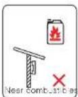
Not in areas where highly flammable materials are stored.
Not in potentially explosive areas.
Not in the cool air directly.
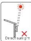
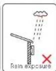
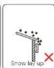
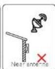
Not near the television antenna or antenna cable.
Not higher than an altitude of about 4000m above sea level.
Not in environment of precipitation or humidity (0-100%)
Be sure the ventilation is good enough
The ambient temperature is in the range of -25°C to +60°C.
The slope of the wall should be within ±5°.
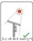
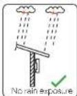
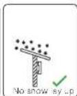
Avoid direct sunlight, rain exposure, snow laying up during installing and operating.

5.2.2 Installation carrier required
The wall or stand hanging the inverter should meet conditions below:
1) Solid brick / concrete, or strength equivalent mounting surface;
2) Inverter must be supported or strengthened if the strength of wall/stand isn't
enough. (such as wooden wall, the wall covered by thick layer of decoration)
Mechanical Installation Mechanical Installation
5.2.3 Installation Angle Required
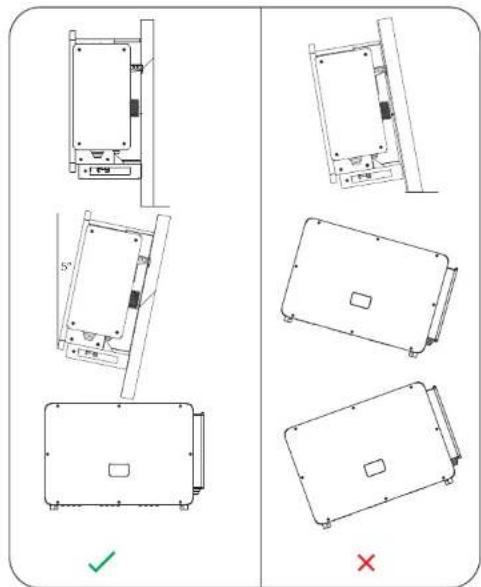
The inclination angle of the installation shall not be greater than 5° and cannot be tilted forward, inverted, excessive back tilted or side tilted.
The inverter shall be installed more than 500 mm above the ground.
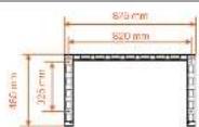
5.2.4 Installation Space Required
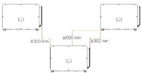
To ensure good heat dissipation and convenient disassembly, the minimum clearance around the inverter shall not be less than the following values, as shown in the following figure.

For multi-inverter installation, please reserve the space of 1200 mm at least between each left and right inverter and at least 600 mm between each upper and lower inverter.
Mechanical Installation Mechanical Installation
5.3 Tools Preparation for Installation and Connection


Additionally required wires
| Required Wires Material Cross Section | Wire Length | ||
| PV cable | Decidated PV wire, copper | 6 mm ^2 | <200 m |
| AC cable (40-125 kW) | Five-core cooper wire | 70 mm ^2 - 240 mm ^2 | <200 m |
| AC cable (136-150 kW) | Four-core copper wire | 70 mm ^2 - 240 mm ^2 | ≤200 m |
| AC cable (40-125 kW) | Five-core aluminium wire | 120 mm ^2 - 240 mm ^2 | <200 m |
| AC cable (136-150 kW) | Four-core aluminium wire | 120 mm ^2 - 240 mm ^2 | ≤200 m |
| Grounding wire | Conventional yellow and green, copper wire | 35 mm ^2 - 70 mm ^2 | ≤150 m |
| Communication cable | Outdoor-rated shielded twisted pair cooper wire | 0.5 mm ^2 0.75 mm ^2 | ≤200 m |
5.4 Check for Transport Damages
Make sure the inverter is intact during transportation. If there are some visible damages, such as cracks, please contact your dealer immediately.
5.5 Packing Lists
Open the package and fetch out the product, check the accessories at first. The packing list shows as below.
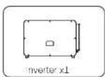
* For the optional accessories, please be subject to the actual delivery.
* Please purchase OT terminals separately.
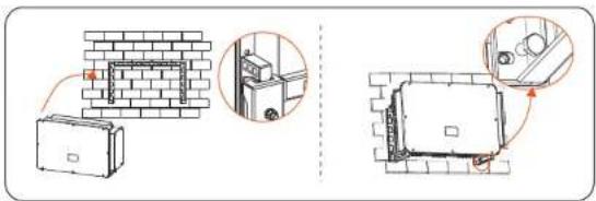
5.6 Installation steps
5.6.1 Installation steps of mounting the inverter on the wall
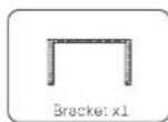
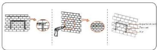
Step 1: Fix the bracket on the wall
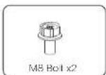
a. Find out the bracket and M8 bolts from the accessory box as below: And prepare M10x80 iron expansion combination in advance. Please kindly note that M10x80 screws are not in the accessory box. Please prepare them in advance.
Bracket x1

M8 Bolt x2
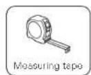
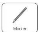
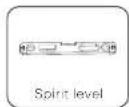
b. Use the bracket as a template for marking the positions of drilling holes on the wall with a spirit level and marker.
c. Use 13 drill to drill holes in accordance with the mark. The depth of the holes shall be at least 65 mm.
d. Insert the expansion screws into the holes, hang the bracket on the screw and fix it with a nut.
Mechanical Installation Mechanical Instella
Step 2: Hang the inverter on the bracket
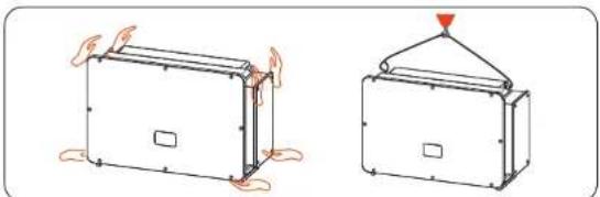
a. Lift up the inverter. Two methods are available for your choice. Method 1: Four installers directly hold the inverter on the two sides and lift it up. Method 2: Install two lifting rings on the two sides of inverter and lift it up.
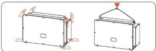
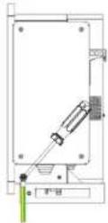
natural_image
Two simple line drawings of a tent-like structure with heat exchangers, one showing fire damage and the other a canopy cover (no text or symbols)b. Hang the inverter on the bracket and secure it on the bracket with M8 bolts. (Torque: 7.0-8.5 N·m)
5.6.2 Installation steps of mounting inverter on the stand
Step 1: Fix the bracket on the stand
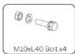
a. Find out the four M10x40 bolt combination, bracket and two M8 bolts from the accessory box as below:
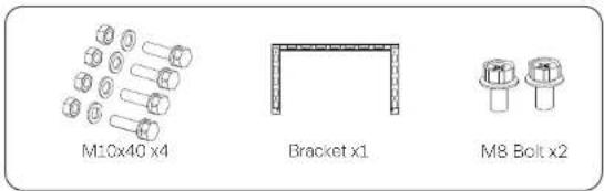
b. Use the bracket as a template for marking the position of drilling holes on the stand with a spirit level and marker.
c. Use Φ12 drill to drill holes in accordance with the mark.
d. Pre-install the bracket on the stand and screw in the M10X40 screws.
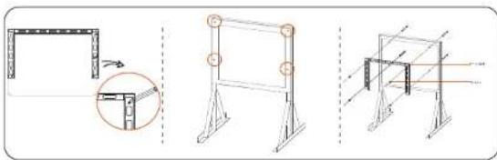
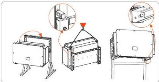
natural_image
Three technical line drawings of structural supports and a frame structure, showing different assembly configurations (no text or symbols present)Step 2: Hang the inverter on the bracket
a. Lift up the inverter. Two methods are available for your choice.
Method 1: Four installers directly hold the inverter on the two sides and lift it up.
Method 2: Install two lifting rings on the two sides of inverter and lift it up.
natural_image
Two technical diagrams showing a rectangular device with base and top views, one with a triangular load or vent, the other with a triangular load (no text or symbols)b. Hang the inverter on the bracket and secure it with M8 bolts. (Torque: 7.0-8.5 N·m)
6. Electrical connection
6.1 Grounding connection
The uncharged metal parts in the photovoltaic power generation system, including the photovoltaic substrate bracket and the metal shell of the inverter, should be reliably grounded. The grounding part of multiple inverters and photovoltaic array shall be connected to the same grounding bus to establish reliable equipotential connection.
Step 1: Make the grounding cable
a. Select OT copper terminal and 35-70 mm² yellow and green conductor with proper length by diagonal pliers. Use wire stripper to strip the insulation layer of the conductor end. The stripped length shall be as shown below. b. Tighten the stripped end and pull the heat-shrink tubing over the grounding cable. The heat-shrink tubing must be at below cable section.
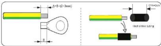
c. Insert the stripped section into the OT copper terminal and crimp with crimping tool.
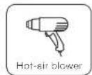
d. Pull the heat-shrink tubing over the stripped section of OT terminal and use hot-air blower to shrink it so that it can be in firm contact with OT terminal.
Step 2: Connect the grounding cable to the inverter.
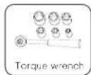
Connect the grounding cable to the inverter and fix it with torque 7.0-8.5 N·m.

WARNING! Be sure the ground wire must be connected!
6.2 PV String Connection

WARNING!
Before connecting the inverter, make sure that the open circuit voltage of the photovoltaic string shall not exceed 1100 V under any conditions, otherwise, the inverter will be damaged.

WARNING!
Do not ground the positive or negative pole of the PV string, otherwise it will cause serious damage to the inverter.

WARNING!
Make sure that the positive and negative poles of the PV string are correctly connected with the corresponding identification of the inverter.

CAUTION!
The actual PV connection shall be consistent with the mode ("Multi" mode or "COM" mode) set on the inverter or SolaX Cloud App.
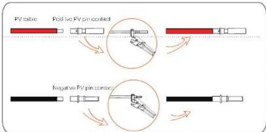
Step 1: Make the PV cable
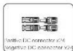
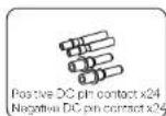
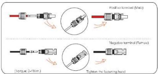
a. Find out the positive/negative x24 DC connector and x24 positive/negative DC pin contact from accessory box.
Positive DC connector x24 Negative DC connector x24

Positive DC pin contact x24 Negative DC pin contact x24
b. Turn off the DC switch and prepare a 4-6 mm² PV cable. Use wire stripper to strip 6 mm insulation layer of the PV cable end.
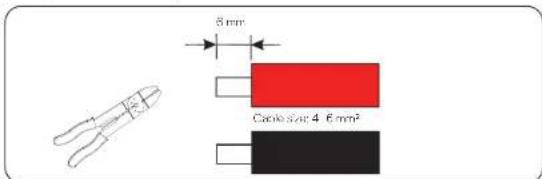
c. Tighten the stripped section and insert it into the PV pin contact. And use terminals press clamp to clamp it so that the stripped section of PV cable is in firm contact with PV pin contact.
d. Insert the PV cable through fastening head and plug (male and female) and force the male or female plug to the cable. You will hear "Click" which indicates the connection is completed. Then tighten the fastening head.
Step 2: Measure the voltage of DC input
Use a multimeter to measure the PV voltage of DC input, verify the polarity of DC input cable, and ensure that the voltage fo each string is within the range of inverter.
Step 3: Connect the PV cable to the inverter
Connect the PV cable to the corresponding PV port on the inverter, shown as below:
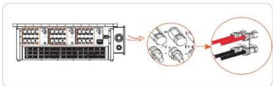
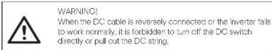
The correct operation is as follows:
-Use a clamp current meter to measure DC string current.
-If it is greater than 0.5 A, please wait until the current is less than 0.5 A.
-Only when the current is less than 0.5 A, can the DC power be cut off and the DC string be pulled out.
The inverter damage caused by improper operation will not be included in the warranty.
Requirements for photovoltaic modules connecting to the same circuit. All PV modules shall be of the same specification.
-All PV modules have the same tilt angle and orientation.
-The open circuit voltage of the PV string shall not exceed 1100 V at the coldest expected temperature in time

WARNING!
Electric shock!
Do not touch live DC wires. When photovoltaic modules are exposed to light, high voltage will occur, which will lead to the risk of electric shock, resulting in death due to contact with DC conductor.
6.3 Grid Connection

WARNING
Ensure electrical connection design meets local national and local standards.

WARNING
The PE wire (ground wire) of the inverter must be reliably grounded.

WARNING
Disconnect the circuit breaker or fuse of inverter and grid connection access point.
Note:
-It is recommended to add a circuit breaker or fuse on the AC side, whose specification is more than 1.25 times of rated AC output current.
-70\~240 mm ^2 copper wire is recommended. If aluminum wire is needed, please check the requirements of the wire and then purchase by yourself.
-Use copper terminal for copper wire, use copper aluminum terminal for aluminum wire, not aluminum terminal directly.

NOTE!
40 kW-70 kW / 75 kW-120 kW inverter adopts 4-pin AC terminal; 136 kW/150 kW inverter adopts 3-pin AC terminal.

NOTE!
The "Delta Grid" in "Setting"-Grid Protection"-Function Choose" is set as "Enable" in default. In this condition, the Neutral wire is not required to be connected. Please set "Delta Grid" to "Disable" before connecting the Neutral wire for 40 kW-70 kW / 75 kW-125 kW inverter.
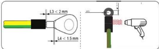
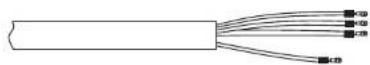
Step 1: Make the AC cable
a. Select the appropriate OT terminal and black, red and yellow and green cable with proper length by wire cutter, and use wire stripper to strip the insulation layer of the AC cable end. The stripped insulation layer shall be 2-3 mm longer than "D" part of OT terminal.
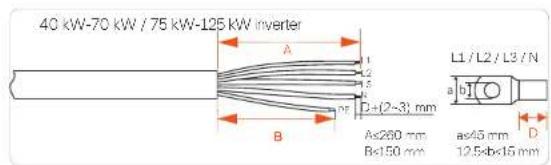
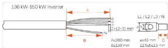
a. Pull the heat-shrink tubing over AC cable.
b. Insert the stripped section into OT terminal and crimp with crimping tool and pull the heat-shrink tubing over the crimped section of OT terminal. Then use hot air blower to shrink it so that they are in firm contact with OT terminal.
40 kW-70 kW / 75 kW-125 kW inverter
136 kW-150 kW inverter
40 kW-70 kW / 75 kW-125 kW inverter
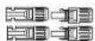
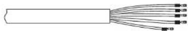
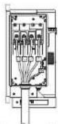
natural_image
Pure diagram of a cable with multiple black connectors, no text or symbols present136 kW-150 kW inverter


natural_image
Simple line drawing of a cylindrical object with a pointed tip and a base, resembling a stylized tool or device (no text or symbols)d. Open the cover of the wiring box.
40 kW-70 kW / 75 kW-125 kW inverter
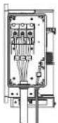
natural_image
Technical line drawing of a rectangular electronic enclosure with mounting holes and a central slot, showing no text or symbols.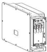
136 kW / 150 kW inverter
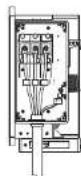
natural_image
Technical line drawing of a rectangular electronic enclosure with mounting holes and a central square (no text or symbols)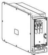
Step 2: Connect the AC cable to the inverter
a. Use a utility knife to cut out the pagoda type protection ring in accordance with the whole cable size, route the AC cable through the pagoda protection ring, and connect it to the AC terminals L1, L2, L3 and N in turn, and tighten it with torque wrench (with the torque of 25\~30 Nm).
40 kW-70 kW / 75 kW-125 kW inverter
Separate PE cable
Multi-core cable
136 kW / 150 kW inverter
Separate PE cable
Multi-core cable
b. Re-install the cover of wiring box and lighten it with screws (with the torque of 5-7 Nm).
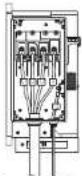
6.4 Communication Connection
6.4.1 Communication signal definition
| Port Pin | Definition | Remark | |
| RS-485-1 | 1 | RS485A IN+ | Inverter RS485 networking or connect the data collector |
| 2 | RS485B IN- | ||
| 3 | RS485 IN-GND | ||
| 4 | RS485A OUT+ | ||
| 5 | RS485B OUT- | ||
| 6 | RS485 OUT-GND | ||
| RS-485-2 | 7 | RS485A METER | Connect the RS485 motor or other devices |
| 8 | RS485B METER | ||
| 9 | V+5V | ||
| 10 | COM GND | ||
| DRM | 11 | DRM1/5 | Reserved for DRM/RRCR |
| 12 | DRM2/6 | ||
| 13 | DRM3/7 | ||
| 14 | DRM4/8 | ||
| 15 | RC/0 | ||
| 16 | CL/0 | ||
| DI | 21 | Digital IN+ | Input digital signal |
| 22 | Digital IN- | ||
| DO | 29 | Digital OUT+ | Output digital signal |
| 30 | Digital OUT- |
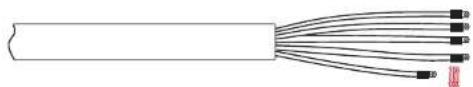
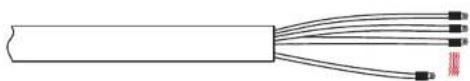
6.4.2 Connection steps of communication cable
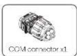
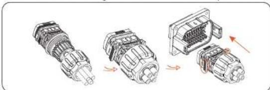
a. Find out the communication terminal from the accessory box and disassemble it into the following parts.
c. Select 0.5-0.75 mm2 conductor and use wire stripper to strip 12-14 mm insulation layer of the cable end and insert the insulated cord end terminal to the cable end. (ENY0512 nylon terminal for 0.5 mm²/22 AWG conductor; ENY7512 nylon terminal for 0.75 mm²/20 AWG conductor) c. Use crimping tool to make the terminal in firm contact with the cable end.
d. Set the nut, crew, seal body, seal ring and body on the communication cable in turn.
e. Insert the tube type terminal into the housing according to the label on it. Push the terminal-inserted housing into the body. There will be a slight sound of "Click", which indicates the connection is completed.
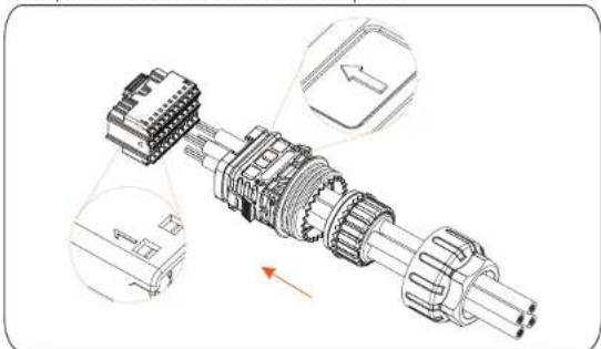
natural_image
Technical illustration of a mechanical assembly with exploded view and close-up views (no text or symbols)f. Push the seal body into seal ring, then push the claw.
g. Clockwise tighten the nut with torque 8+/-2 N·m.
h. Keep the buttons on both sides pressed and connect it to the COM port of the inverter. There will be a slight sound of "Click" if it is correctly connected.
natural_image
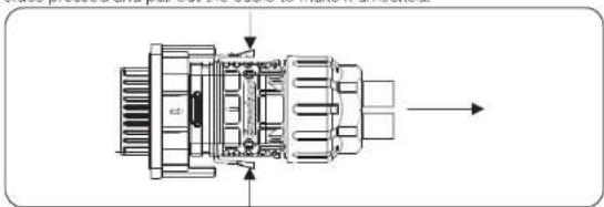
Diagram showing three stages of an automotive electrical connector assembly (no text or labels)6.4.3 Release steps of communication cable
For releasing the communication cable, please keep the buttons on the two sides pressed and pull out the cable to make it unlocked.
natural_image
Technical line drawing of an internal combustion engine component with no visible text or symbols6.5 Parallel Connection
6.5.1 Datahub Parallel Connection
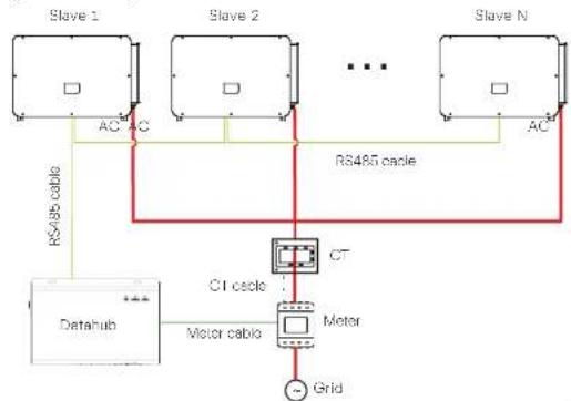
The series inverter provides the parallel connection function when connected with Datahub, which could support at most 60 inverters to parallel in one system and can control zero injection to the grid with a meter installed in the main circuit. In this parallel system, the Datahub will be the master of the system, and all the inverters are the slaves. The Datahub can communicate with all the slave inverters.
Diagram: Parallel system with Datahub
flowchart
graph TD
    subgraph Slave_1
        A["AC"] --> B["RS485 cable"]
    end
    subgraph Slave_2
        C["AC"] --> D["RS485 cable"]
    end
    subgraph Slave_N
        E["AC"] --> F["RS485 cable"]
    end
    G["Datahub"] --> H["Motor cable"]
    H --> I["CT motor"]
    I --> J["Grid"]
    K["Motor cable"] --> I
    style Slave_1 fill:#f9f,stroke:#333
    style Slave_2 fill:#f9f,stroke:#333
    style Slave_N fill:#f9f,stroke:#333
    style Datahub fill:#ccf,stroke:#333
    style CT_cable fill:#cff,stroke:#333
    style Motor_cable fill:#ffc,stroke:#333
Note!

Before operation, please make sure that the inverters meet the following conditions:
- All the inverters are recommended to be the same series;
- The firmware version of all inverters shall be the same.
Otherwise, the parallel function cannot be used. - Ensure the RS485 cable length is less than 200 m.
Note!
Before connecting the Datahub to the parallel system, please check that the inverters' settings meet the following conditions: 1. The "Modbus Fuction" should be "COM485".
- The addresses of all the inverters in the "RS485 CommAddr" should be different. Otherwise, please reset the RS485 communication addresses.
- Wiring operation
a) Connect one end of an RS485 communication cable with Datahub, and the other end with one of the slave inverters.
b) Connect all the slave inverters with each other with RS485 cables.
c) Connect the meter with the Datahub and the mains.
For the details, please refer to the user manual of Datshub.
6.5.2 Modbus Parallel Connection
The device offers Dstahub parallel connection as well as master-slave parallel connection for up to 10 machines, with one serving as the master and the others as slaves. A 485 communication wire must be attached directly to the inverter. The devices are connected in a bus type connection mode. The Master's RS485-2 is connected to the electricity meter, and the Master and slave are connected to the RS485 1 port.
The bus topology is shown as follows:
flowchart
graph TD
    subgraph Master
        A["Master"] -->|R54A5| B["Slave 1 Slave N"]
        A -->|CT Comm| C["Transformer"]
        A -->|AC| C
    end
    subgraph Slave 1 Slave N
        B -->|R54A5| D["Master"]
        B -->|CT Comm| E["Slave 1 Slave N"]
        B -->|AC| F["Transformer"]
    end
    subgraph Transformer
        C --> G["Grid"]
    end
    Note: Green line (RT) and red line (CC) are connected to the Master node. The chart includes a dashed line for CT and solid lines for AC.
The interconnection between the host and slave is made by Pins 1, 2, 4, 5, and Pins 7, 8, which are connected to the electricity meter.
| Port Pin | Definition | |
| RS-485-1 | 1 | RS485A IN+ |
| 2 | RS485B IN- | |
| 4 | RS485A OUT+ | |
| 5 | RS485B OUT- | |
| RS-485-2 | 7 | RS485A METER |
| 8 | RS485B METER |
6.6 PLC Box Connection (Optional)
The inverter supports to be connected with PLC Box. With PLC Box, RS485 cable is not required for communication. Purchase the product from supplier if needed. Refer to PLC Box Quick Installation Guide for detailed installation and connection of PLC Box.
For monitoring on SoleX Cloud, Datahub shall be installed to communicate with PLC Box. The communication between PLC Box and inverters is power line, and from PLC Box to Datahub is Rs485.
Please note that for this application, all the inverter models must be the PLC integrated models. (PLC function is optional, you will need to purchase the models with PLC integrated)
flowchart
graph TD
    A["PV String"] --> B["Inverter"]
    C["PV String"] --> D["Inverter"]
    E["PV String"] --> F["Inverter"]
    B --> G["PLC BOX"]
    D --> G
    F --> G
    G --> H["Transformer"]
    H --> I["Grid"]
    style A fill:#f9f,stroke:#333
    style C fill:#f9f,stroke:#333
    style E fill:#f9f,stroke:#333
    style F fill:#f9f,stroke:#333
    style G fill:#ccf,stroke:#333
    style H fill:#cfc,stroke:#333
    style I fill:#fcc,stroke:#333

NOTE!
PLC connection requires a transformer to step up to the medium voltage utility grid.
6.7 Control the Output Power by Connecting a Radio Ripple Control Receiver (RRCR)
The inverter can be connected to a RRCR (Radio Ripple Control Receiver) in order to dynamically control the output power of all the inverters.
Users can control and limit the active power on the LCD by setting the active power limitation, which is a fixed power limit as a percentage, i.e. 0%, 30%, 60% and 100%.
Connection:
Connect the RRCR directly to the inverter communication board through the DRM. The following table describes the connector pin assignment and functionality:

NOTE!
The DRM and RRCR ports can be shared.
| Port Pin | Definition | Description | Connect to RRCR | |
| DRM/RRCR | 11 | DRM1/5 | Input 1 | K1 - Relay 1 output |
| 12 | DRM2/6 | Input 2 K2 | - Relay 2 output | |
| 13 | DRM3/7 | Input 3 K3 | - Relay 3 output | |
| 14 | DRM4/8 | Input 4 K4 | - Relay 4 output | |
| 15 RG/O | VCC Relays common node | |||
The inverter is preconfigured to the following RRCR power levels:
| COM port Pin 11 | COM port Pin 12 | COM port Pin 13 | COM port Pin 14 | Active power | Cos(φ) |
| Short circuit with RG/0 | / | / | / | 0% | 1 |
| / | Short circuit with RG/0 | / | / | 30% | 1 |
| / | / | Short circuit with RG/0 | / | 60% | 1 |
| / | / | / | Short circuit with RG/0 | 100% | 1 |
To set the fixed power control:
Enter "Active Power" page, choose "Enable" to activate the function.
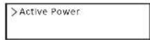
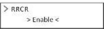
in the "RRCR" page. RRCR1 2.3, 4 can be set for the corresponding values 0%, 30%, 60%, and 100% by default. Users can also configure these values as needed.
The values correspond to varied AC output power. For example, the 30% is in accordance with the rated power output of 30%.
| >RRCR1>0.0%< |
| >RRCR2>30.0%< |
| >RRCR3>60.0%< |
| >RRCR4>100.0%< |
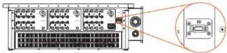
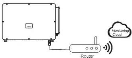
6.8 Monitoring Connection
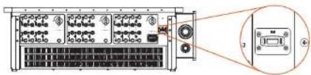
Monitoring Cloud is an application that can communicate with the inverter via Wi-Fi/LAN/4C. It can realize alarm queries, parameter configuration, daily maintenance and other functions. This is a convenient maintenance platform.
Plug Dongle into "USB" port at the bottom of the inverter. After the DC side or AC side is powered on, the APP and inverter can be connected. Please refer to the corresponding manual for details.
natural_image
Diagram of a server rack with ports and connectors, showing an inset view of a device (no text or labels visible)Wi-Fi connection
Wi-Fi dongle connects to a local network to enable access to the Monitoring Cloud platform.
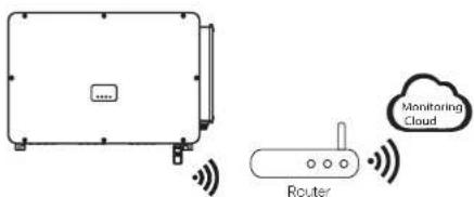
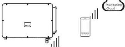
LAN connection
If Wi-Fi isn't suitable, the LAN dongle enables users to connect to the network via an ethernet cable. Ethernet allows for a much more stable connection with less interference.
4G connection
4G dongle allows you to use a 4G connection to monitor your system without the option of connecting to a local network. (This product is not available in the UK)
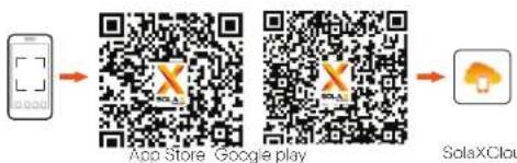
APP Setting
Scan the QR code to download SolaXCloud App. Create a new account and follow the tutorial on the SolaXCloud APP or the App guide at https://www.solaxcloud.com/ to set the WiFi configuration.
Touch the Inverter icon and you can add new inverter in the site page, and check details out in the Inverter section of this guide.
flowchart
graph LR
    A["Mobile Device"] --> B["App Store"]
    B --> C["Google Play"]
    C --> D["SolaXCloud"]
The users can also set up the inverter remotely by downloading the SolaXCloud APP. The default site information will be shown after the end user logs in. The power and energy data displayed on this page is a synthesis of all the chosen inverter data contained in this site. Select or create a new site, and then the user can add and set up the inverter at the site.
Or the user can scan the QR code to watch the WiFi configuration video on YouTube, and study how to set the inverter.

7. Start the Inverter
- After the inverter is checked, then conduct the following steps.
a) Check that device is fixed well on the wall or stand.
b) Make sure all the DC breakers and AC breakers are disconnected.
c) AC cable is connected to grid correctly.
d) All PV panels are connected to inverter correctly, DC connectors which are
not used should be sealed by cover.
e) Turn on the DC switch to the "On" position.
- Start the inverter
Turn on the AC switch between the inverter and the power grid.
Turn on the DC switch between the PV string and the inverter if there is any.
Turn on the DC switch at the bottom of the inverter.
Inverter will start automatically when PV panels generate enough energy.
Check the status of LED indicators and LCD screen, the LED indicators should be
blue and the LCD screen should display the main interface.
For the inverter with LED indicators:
If the LED indicator is not on, please check the below:
- All the connections are right.
- All the external circuit breakers are closed.
- The DC switch of the inverter is in the "ON" position.
| 1. FTR indicator status indicators definition | ||
| Communication signal Indicator (Vcc) | Always light or | The inverters communication is named |
| - Idosing | The communication data is sent to the secret for calling it. | |
| DC power signal indicator (gpre) | Always light or | The inverters in grid connected state. |
| - Idosing | If the fault signals light is on, if indicators errors occur on the inverters LCC state, if the fault signal light is off, it indicates no errors occur on the inverters LCC state and at least one channel of MFP1 linear voltage is higher than 200 V. | |
| Always light or | The input voltage at all channels of MFP1 is less than 200 V, DC X switch is not turned on. | |
| Grid connection indicator (gpre) | Always light or | The inverters in grid connected state. |
| - Idosing | If the fault signals in other states is on, it indicates errors occur on the inverters AC state, if the fault signal indicator is off, AC Q will be connected and the inverters is not in grid connected state. | |
| Always light or | The inverters are connected to the part. | |
| Lowest fault indicator (RCC) | Always light or | The inverters is faulty. |
| - Idosing | The inverters cannot warning. | |
| Always light or | The inverters is currently in a normal state, and there is no fault. | |
Note:
1 When the inverter is in software upgrading state, all the indicators are blinking by horse racing LED in circle;
2 When the inverter upgrade fails, other three indicators will be off except the inverter fault indicator (Red);
3 After the inverter upgrade succeeded, all the indicators will be off;
4 When the inverter is in the aging mode, the inverter fault indicator (Red) is
flashing and other indicators keep the current state.
Startup of the Inverter
Startup of the Inverter
For the inverter with LCD screen:
Below is the three different states when operating, which means inverter starting up successfully.
Waiting: Inverter is waiting before checking when DC input voltage from panels is greater than 160 V (lowest start-up voltage) but less than 200 V (lowest operating voltage).
Checking: Inverter will check DC input environment automatically when DC input voltage from the PV panels exceeds 200 V and PV panels have enough energy to start inverter.
Normal: Inverter begins to operate normally, meanwhile the LCD displays the main interface. Enter the setting interface to set the parameters when it is the first time to start up.
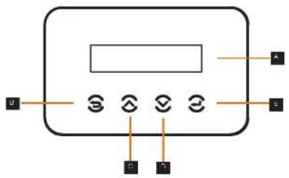
| Object | Name | Description |
| A | LCD Screen | Display the information of the inverter. |
| B | ESC key | Return to the previous interface or cancel the setting |
| C | Up key | Move the cursor up or increase the setting value. |
| D | Down key | Move the cursor down or decrease the setting value. |
| E | Enter key | Enter the selected interface or confirm the setting. |
8. Firmware Upgrading
- Upgrade preparation
1) Prepare a U disk (USB 2.0 / USB 3.0);

CAUTION!
Please make sure that the format is FAT or FAT 32.
2) Contact our service support to get the update files ("*.bin" and "*.txt" file), and store the two files in the root path of the U disk.
Files:
FORTH_Vxxx.xx.bin
UpdateConfig.txt

CAUTION!
The bin name listed in the "*.txt" file must be same as the "*.bin" name.
- Upgrade steps
USB disk can be plugged when the inverter is in normal status.
1) Plug the U disk into the upgrading port below: If the Wi-Fi dongie is connected to the port, please remove the dongie first.

NOTE!
After U disk plug in, the four indicator lights will be blinking in turn. (Communication indicator: blue; DC connection indicator: green; Grid connection indicator: green; Alarm indicator: Red)
2) Wait approximately 15 seconds. The system will start upgrading when the four indicator lights turn off and the buzzer starts buzzing.
3) When the buzzer stops buzzing and the indicator lights start blinking again, it means that ARM program is upgraded successfully. And then the system will start other programs by upgrading.
If upgrading succeeds, the communication indicator (blue) turns off and other indicators are on;
If upgrading fails, only alarm indicator (red) is on. Please contact our service support for solutions.

NOTE!
After upgrading finished, the current state of indicator will be kept for 1 min and the inverter will be switched on automatically.
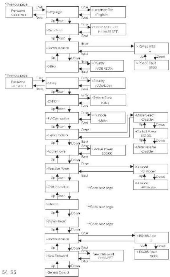
9 Setting for Inverter with LCD
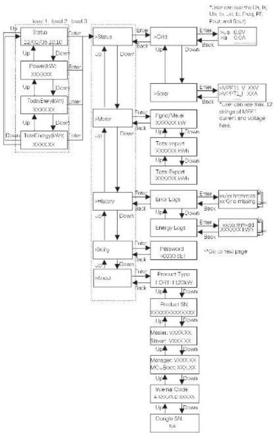
flowchart
System architecture flowchart for MPI control system, showing data flow between status, motor, and product modules with status flags and control signals.Setting
flowchart
```mermaid
graph TD
    A["Password >0000 SET"] --> B["Enter"]
    B --> C["Language Set >English"]
    C --> D["Up Down"]
    D --> E[">=Data Time"]
    E --> F["Up Down"]
    F --> G["Communication"]
    G --> H["Up"]
    H --> I["Down"]
    I --> J[">=Safety"]
    J --> K["Up"]
    K --> L[">=ON/OFF"]
    L --> M["Up Down"]
    M --> N[">=PV Connection"]
    N --> O["Up Down"]
    O --> P[">=Export Control"]
    P --> Q["Up"]
    Q --> R["Down"]
    R --> S[">=Active Power"]
    S --> T["Up"]
    T --> U["Down"]
    U --> V[">=Reactive Power"]
    V --> W["Up"]
    W --> X[">=Grid Protection"]
    X --> Y["Up Down"]
    Y --> Z[">=Choices"]
    Z --> AA["Up"]
    AA --> AB["Down"]
    AB --> AC[">=System Reset"]
    AC --> AD["Up"]
    AD --> AE["Down"]
    AE --> AF[">=Communication"]
    AF --> AG["Up"]
    AG --> AH["Down"]
    AH --> AI[">=New Password >0000 SET"]
    AI --> AJ["Up"]
    AJ --> AK["Down"]
    AK --> AL[">=General Control"]

    subgraph "Previous page"
        B
        C
        D
        E
        F
        G
        H
        I
        J
        K
        L
        M
        N
        O
        P
        Q
        S
        T
        U
        V
        W
        X
        Y
        Z
        AA
        AB
        AC
        AD
        AE
        AF
        AG
        AH
        AI
    end

    subgraph "Previous page"
        B
        C
        D
        E
        F
        G
        H
        I
        J
        K
        L
        M
        N
        O
        P
        Q
        S
        T
        U
        V
        W
        X
        Y
        Z
        AA
        AB
        AC
        AD
        AE
        AF
        AG & AH & AI & AJ & AK & AL & AM & AN & AO & AP & AQ & AR & AS & AT & AU & AV & AW & AX & AY & AZ & BA & BB & BC & DA & DE & DF & DG & DH & DI & DJ & DK & DL & DV & DW & DX & DR & DW & DW & ID & ID & IDA & IDB & IDC & IDF & IDG & IDH & IDI & IDJ & IDK & IDL & IDM & IDN & IDO & IDP & IDQ & ID R & ID S & ID T & ID U & ID V & ID W & ID X & ID Y & ID Z & ID AA & ID AB & ID AC & ID AD & ID AE & ID AF & ID AF & ID AF & ID AF & ID AF & ID AF & ID AF & ID AF & ID AF & ID AF & ID AF & ID AF & ID AF & ID AF & ID AF & ID AF & ID AF & ID AF & ID AF & ID AF & ID AF & ID AF & ID AF & ID AF & ID AF & ID AF & ID AF & ID AF & ID AF & ID AF & ID AF & ID AF & ID AF & ID AF &
    end

    %% Note: The diagram shows a hierarchical flow of user interactions and access to the system. The labels on the nodes are in English and Chinese. The arrows indicate directional relationships between user actions and their corresponding functions. The numbers inside the nodes represent the number of users for each action. The arrows indicate the direction of interaction from top-left to bottom-right. The numbers inside the nodes represent the number of users for each action within the system. Numbers inside the nodes represent the number of users for each action in the system. The arrows indicate the direction of interaction between each action's own user.
Setting
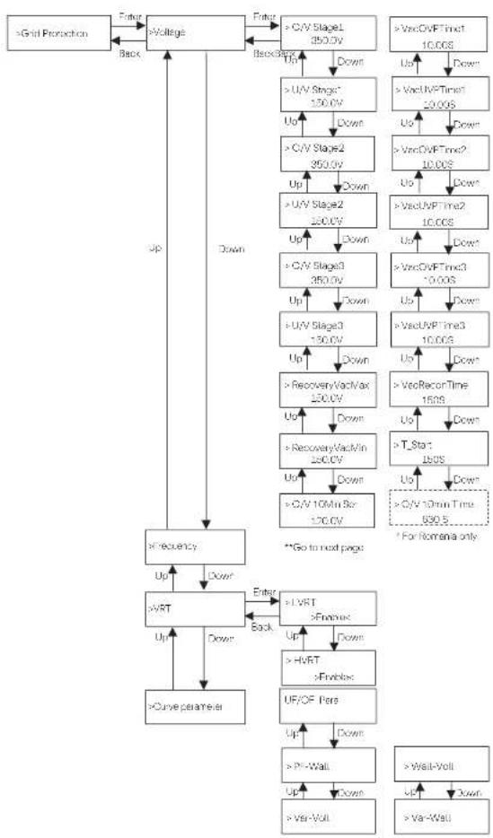
flowchart
graph TD
    A[">Grid Protection"] --> B[">Voltage"]
    B --> C["Up"]
    B --> D["Down"]
    C --> E[">C/V Stage1 250.0V"]
    D --> F[">U/V Stage* 150.0V"]
    E --> G["Down"]
    F --> H[">U/V Stage2 350.0V"]
    G --> I["Down"]
    H --> J[">C/V Stage2 200.0V"]
    I --> K["Down"]
    J --> L[">U/V Stage3 350.0V"]
    K --> M["Down"]
    L --> N[">C/V Stage3 150.0V"]
    M --> O["Down"]
    N --> P[">U/V Stage3 100.0V"]
    O --> Q["Down"]
    P --> R[">RecoveryVacMax 100.0V"]
    Q --> S["Down"]
    R --> T[">RecoveryVacMin 200.0V"]
    T --> U["Down"]
    S --> V[">C/V 10Min Bar 120.0V"]
    U --> W["Down"]
    V --> X[">C/V 10min Time 890.5"]
    W --> Y["For Nomena only"]
    Z[">Curve parameter"] --> AA[">VRT"]
    AA --> AB["Up"]
    AA --> AC["Down"]
    AB --> AD["Enter"]
    AC --> AE["Back"]
    AD --> AF[">LVRT >Enable"]
    AF --> AG["Up"]
    AF --> AH["Down"]
    AG --> AI[">HVRT >Enable"]
    AI --> AJ["Up"]
    AI --> AK["Down"]
    AH --> AL["UF/OF Pers"]
    AL --> AM["Up"]
    AL --> AN["Down"]
    AM --> AO[">PI-Wall"]
    AO --> AP["Up"]
    AO --> AQ["Down"]
    AP --> AR[">Var-Voll"]
    AR --> AS["Up"]
    AR --> AT["Down"]
    AS --> AU[">Wall-Voll"]
    AU --> AV["Up"]
    AU --> AW["Down"]
Setting
Setting
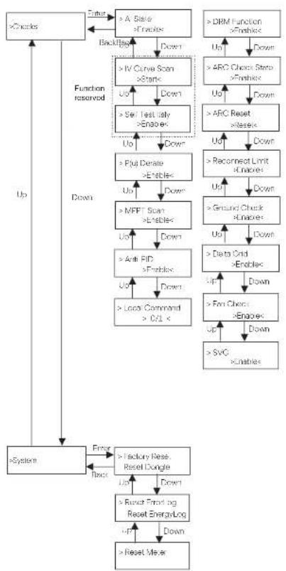
flowchart
graph TD
    A[">Check"] --> B["> A Sistel >Enable"]
    B --> C["> Backflip"]
    C --> D["> IV Curve Scan >Static"]
    D --> E["> Set Test Only >Enable"]
    E --> F["> Put Denate >Enable"]
    F --> G["> MFFT Scan >Enable"]
    G --> H["> Anti PID >Enable"]
    H --> I["> Local Command >C/L ×"]
    I --> J["> System"]
    J --> K["> Factory Rese. Reset Dongle"]
    K --> L["> Reset Forwarding Reset EnergyLog"]
    L --> M["> Reset Meter"]
    N["> DRM Function >Enable"] --> O["> ARC Check Strip >Enable"]
    O --> P["> ARC Reset >Enable"]
    P --> Q["> Recornerct Limit >Enable"]
    Q --> R["> Ground Check >Enable"]
    R --> S["> Data Grid >Enable"]
    S --> T["> Fm Check >Enable"]
    T --> U["> SvG >Enable"]
    U --> V["> Reset Meter"]
    W["Up"] --> X["Down"]
    X --> Y["Down"]
    Y --> Z["Up"]
    Z --> AA["Down"]
    AA --> AB["Up"]
    AB --> AC["Down"]
    AC --> AD["Up"]
    AD --> AE["Down"]
    AE --> AF["Up"]
    AF --> AG["Down"]
    AG --> AH["Up"]
    AH --> AI["Down"]
    AI --> AJ["Up"]
    AJ --> AK["Down"]
    AK --> AL["Up"]
    AL --> AM["Down"]
    AM --> AN["Up"]
    AN --> AO["Down"]
    AO --> AP["Up"]
    AP --> AQ["Down"]
    AQ --> AR["Up"]
    AR --> AS["Down"]
    AS --> AT["Up"]
    AT --> AU["Down"]
    AU --> AV["Up"]
    AV --> AW["Down"]
    AW --> AX["Up"]
    AX --> AY["Down"]
    AY --> AZ["Up"]
    AZ --> BA["Down"]
    BA --> BB["Up"]
    BB --> BC["Down"]
    BC --> BD["Up"]
    BD --> BE["Down"]
    BE --> BF["Up"]
    BF --> BG["Down"]
    BG --> BH["Up"]
    BH --> BI["Down"]
    BI --> BJ["Up"]
    BJ --> BK["Down"]
    BK --> BL["Up"]
    BL --> BM["Down"]
    BM --> BN["Up"]
    BN --> BO["Down"]
    BO --> BP["Up"]
    BP --> BQ["Down"]
    BQ --> BR["Up"]
    BR --> BS["Down"]
    BS --> BT["Up"]
    BT --> BU["Down"]
    BU --> BV["Up"]
    BV --> BW["Down"]
    BW --> BX["Up"]
    BX --> BY["Down"]
    BY --> BZ["Up"]
    BZ --> CA["Down"]
    CA --> CB["Up"]
    CB --> CC["Down"]
    CC --> CD["Up"]
    CD --> CE["Down"]
    CE --> CF["Up"]
    CF --> CG["Down"]
    CG --> CH["Up"]
    CH --> CI["Down"]
    CI --> CJ["Up"]
    CJ --> CK["Down"]
    CK --> CL["Up"]
    CL --> CM["Down"]
    CM --> CN["Up"]
    CN --> CO["Down"]
    CO --> CP["Up"]
    CP --> CQ["Down"]
    CQ --> CR["Up"]
    CR --> CS["Down"]
    CS --> CT["Up"]
    CT --> CU["Down"]
    CU --> CV["Up"]
    CV --> CW["Down"]
    CW --> CX["Up"]
    CX --> CY["Down"]
    CY --> CZ["Up"]
    CZ --> DA["Down"]
    DA --> DB["Up"]
    DB --> DC["Down"]
    DC --> DD["Up"]
    DD --> DE["Down"]
    DE --> DF["Up"]
    DF --> DG["Down"]
    DG --> DH["Up"]
    DH --> DI["Down"]
    DI --> DJ["Up"]
    DJ --> DK["Down"]
    DK --> DL["Up"]
    DL --> DM["Down"]
    DM --> DN["Up"]
    DN --> DO
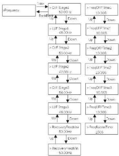
flowchart
graph TD
    A[">Frequency"] --> B[">Q/F Stage1 52.00 Hz"]
    B --> C[">U/F Stage1 48.00 Hz"]
    C --> D[">Q/F Stage2 53.00 Hz"]
    D --> E[">U/F Stage2 47.00 Hz"]
    E --> F[">Q/F Stage3 54.00 Hz"]
    F --> G[">U/F Stage3 46.00 Hz"]
    G --> H[">RecoveryYre0Min 50.00 Hz"]
    H --> I[">RecoveryYre0Min 50.00 Hz"]
    I --> J[">FreqOFF Time2 10.00S"]
    J --> K[">FreqOFF Time1 10.00S"]
    K --> L[">FreqOFF Time2 10.00S"]
    L --> M[">FreqOFF Time3 10.00S"]
    M --> N[">FreqOFF Time2 10.00S"]
    N --> O[">FreqOFF Time3 10.00S"]
    O --> P[">FreqOFF Time2 10.00S"]
    P --> Q[">FreqOFF Time3 10.00S"]
    Q --> R[">FreqOFF Time2 10.00S"]
    R --> S[">FreqOFF Time3 10.00S"]
    S --> T[">FreqOFF Time2 10.00S"]
    T --> U[">FreqOFF Time3 10.00S"]
    U --> V[">FreqOFF Time2 10.00S"]
    V --> W[">FreqOFF Time3 10.00S"]
    W --> X[">FreqOFF Time2 10.00S"]
    X --> Y[">FreqOFF Time3 10.00S"]
    Y --> Z[">FreqOFF Time2 10.00S"]
    Z --> AA[">FreqOFF Time3 10.00S"]
    AA --> AB[">FreqOFF Time2 10.00S"]
    AB --> AC[">FreqOFF Time3 10.00S"]
    AC --> AD[">FreqOFF Time2 10.00S"]
    AD --> AE[">FreqOFF Time3 10.00S"]
    AE --> AF[">FreqOFF Time2 10.00S"]
    AF --> AG[">FreqOFF Time3 10.00S"]
    AG --> AH[">FreqOFF Time2 10.00S"]
    AH --> AI[">FreqOFF Time3 10.00S"]
    AI --> AJ[">FreqOFF Time2 10.00S"]
    AJ --> AK[">FreqOFF Time3 10.00S"]
    AK --> AL[">FreqOFF Time2 10.00S"]
    AL --> AM[">FreqOFF Time3 10.00S"]
    AM --> AN[">FreqOFF Time2 10.00S"]
    AN --> AO[">FreqOFF Time3 10.00S"]
    AO --> AP[">FreqOFF Time2 10.00S"]
    AP --> AQ[">FreqOFF Time3 10.00S"]
    AQ --> AR[">FreqOFF Time2 10.00S"]
    AR --> AS[">FreqOFF Time3 10.00S"]
    AS --> AT[">FreqOFF Time2 10.00S"]
    AT --> AU[">FreqOFF Time3 10.00S"]
    AU --> AV[">FreqOFF Time2 10.00S"]
    AV --> AW[">FreqOFF Time3 10.00S"]
    AW --> AX[">FreqOFF Time2 10.00S"]
    AX --> AY[">FreqOFF Time3 10.00S"]
    AY --> AZ[">FreqOFF Time2 10.00S"]
    AZ --> BA[">FreqOFF Time3 10.00S"]
    BA --> BB[">FreqOFF Time2 10.00S"]
    BB --> BC[">FreqOFF Time3 10.00S"]
    BC --> BD[">FreqOFF Time2 10.00S"]
    BD --> BE[">FreqOFF Time3 10.00S"]
    BE --> BF[">FreqOFF Time2 10.00S"]
    BF --> BG[">FreqOFF Time3 10.00S"]
    BG --> BH[">FreqOFF Time2 10.00S"]
    BH --> BI[">FreqOFF Time3 10.00S"]
    BI --> BJ[">FreqOFF Time2 10.00S"]
    BJ --> BK[">FreqOFF Time3 10.00S"]
    BK --> BL[">FreqOFF Time2 10.00S"]
    BL --> BM[">FreqOFF Time3 10.00S"]
    BM --> BN[">FreqOFF Time2 10.00S"]
    BN --> BO[">FreqOFF Time3 10.00S"]
    BO --> BP[">FreqOFF Time2 10.00S"]
    BP --> BQ[">FreqOFF Time3 10.00S"]
    BQ --> BR[">FreqOFF Time2 10.00S"]
    BR --> BS[">FreqOFF Time3 10.00S"]
    BS --> BT[">FreqOFF Time2 10.00S"]
    BT --> BU[">FreqOFF Time3 10.00S"]
    BU --> BV[">FreqOFF Time2 10.00S"]
    BV --> BW[">FreqOFF Time3 10.00S"]
    BW --> BX[">FreqOFF Time2 10.00S"]
    BX --> BY[">FreqOFF Time3 10.00S"]
    BY --> BZ[">FreqOFF Time2 10.00S"]
    BZ --> CA[">FreqOFF Time3 10.00S"]
    CA --> CB[">FreqOFF Time2 10.00S"]
    CB --> CC[">FreqOFF Time3 10.00S"]
    CC --> CD[">FreqOFF Time2 10.00S"]
    CD --> CE[">FreqOFF Time3 10.00S"]
Setting
Setting
LCD Digital Display
The main interface (Level 1) is the default interface, the inverter will automatically jump to this interface when the system started up successfully or not operated for a period of time.
"Status" shows the time and the current status "Waiting", "Checking", "Running", "Fault" and "Upgrading"; "Power" means the timely output power; "TodayEnergy" means the power generated within the day; "TotalEnergy" means the power generated until now. Press "Up" and "Down" to review the information.
Waiting 22/02/08 10:10
Menu interface
The menu interface (Level 2) is a transfer interface for the user to get into other interface to change the setting or obtain the information. -User can get into this interface by pressing "Enter" key when LCD displays the main interface.
-User can select "Up" and "Down" key, and press "Enter" to confirm the selection.
==Menu==
Status Meter
- Status
The status function contains "Grid" and "Solar". Press "Up" and "Down" to select and press "Enter" to confirm the selection, press "ESC" to return to menu.
== Status ==
Grid Solar
a) Grid
This status shows the current grid condition such as voltage, current, and output power, etc. Pout measures the output of the inverter; Pgrid means active power; Gout means reactive power; Sout means the apparent power. Press "Up" and "Down" button to review the parameter, press "ESC" to return to Status.
- - - - Grid - - - -
Ua xxx.xxV la xxxx.xA
b) Solar
This interface shows the input current of PV. Totally up to 12 strings of MPPT current and voltage can be checked for the inverter.
- Meter
The user can check the import and export energy by this function. There are three parameters: "Pgrid/Meter", "Total Import" and "Total Export". Press "Up" and "Down" to review the values. If no meter is connected, the parameters here will display 0.
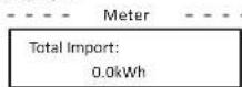
• History
History contains error logs and energy logs. The Error log contains error information happened. It can record six items at most. Press "Up" and "Down" button to review parameter. Press "ESC" to return to the main interface.
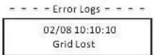
The Energy log contains the energy generated within the day. Press "Up" and "Down" button to select the date to check the log recorded on that day. Press "ESC" to return to the main interface.
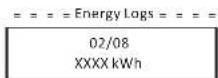
- Settings
Setting function is used for setting the inverter for safety, system on/off, PV connection mode, etc. To set the parameter, please input the password. For users, the default password is "0000", which allows the user to review and modify "Language", "Date Time", "Communication" and "Safety".
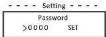
Setting
Setting
a) Language
Here user can set the language. At present, English is only available for choosing.
= = = =Language =
Language Set
English <
b) Date Time
This interface is for the user to set the system date and time. Increase or decrease the word by pressing "Up" or "Down" key. Press "Enter" to confirm and alternate to next word. After all the words are confirmed, select "SET" and press "Enter" to confirm the password.
= = = =Language =
Y2022-M03-D22
H11:M35 S E T
c) Communication
RS485 Addr: the modbus address of the external communication protocol.
RS485 Baud: The Baud rate of the external communication protocol. At present, 4900, 9600 and 19200 are supported, and the default is 9600.
With this function, the inverter can communicate with the computer, through which the operating status of the inverter can be monitored. When multiple inverters are monitored by one computer, RS485 communication addresses of different inverters need to be set.
Communication Parameter -
RS485 Addr
1
- Communication Parameter -
RS485 Baud
9600
d) Safety
The user can only view the safety standard here.
= = = = Safety = = = =
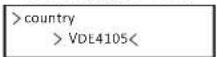
For installers, the default password is "2014", which allows the installer to review and modify necessary settings complying to the local rules and regulations. If further advanced setting is required, please contact us or the distributor for assistance. Press "Enter to enter the password setting interface, press "up" and "Down" when it is flashing, then press "Enter" to confirm the set value. Finally, select "SET" and press "Enter" to confirm the password.
== = = Setting == ==

60 61
After inputting the password, the information of the LCD interface is shown as below.
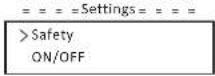
a) Safety
The installer can set the safety standard here according to different countries and grid tied standards. There are several standards for choice.

b) ON/OFF
"ON" means the inverter is in working state, and the inverter is in the default state.
"OFF" means that the inverter stops running and only the LCD screen is on.
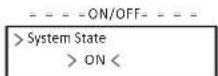
c) PV Connection
The user can select the PV connection type by this function.
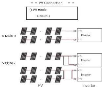
flowchart
graph TD
    A[">PV mode"] --> B[">Multi"]
    C[">COM"] --> D[">Multi"]
    B --> E["Inverter"]
    D --> F["Inverter"]
    E --> G["Inverter"]
    F --> H["Inverter"]
Setting
Setting
d) Export Control
With this power control function, the inverter can control the energy exported to the grid. The "Control Power" can be set by the installer. When you set 100% for control power, it means the energy can be exported to grid with full power. When you set 0%, Exporting to grid is limited. Please set the percentage according to the actual need.
Choose "Disable" means the function will not be activated. Press "Up" and "Down" button to select and press "Enter" to confirm it.
| - - - Export Control | - - - Export Control |
| > Mode Select | > Control Power |
| > Disable < | 1.0% |
If the meter is connected reversely, please the enable "Meter reverse" function.
| = = = Export Control |
| > Meter reverse |
| > Enable < |
installer can set "Soft Limit" and "Hard Limit" for export control.
e) Active power
This interface is used to set the reactive power according to the requirement of utility grid.
| = = = = Ap Set |
| >Active Power100.0 |
f) Reactive power
This interface is used to set the active power. Please set the value according to the requirement of utility grid.
| = = = =Rp Set |
| >Q Mode |
| >Disable < |
g) Cria Protection
Usually end user do not need to set the grid protection. All default value have been set before leaving factory according to safety rules.
If reset is needed, any changes should be made according to the requirements of local grid.
| = = = Grid Protection | = = = |
| > Voltage | |
h) Checks
This interface is used to activate the needed functions, including "AI State", "P(u)Derate", "I-V Curve", "MPPT Scan", "ARC detection", "DRM", etc. The users can input the default password to review and modify the functions above.
| Checks |
| > AI State |
| > Enable< |
• I-V Curve Scan
Enable to check the current-voltage characteristic curve of the PV module, which in turn gives an indication of any abnormalities, and its degradation and health.
• DRMO
In Australia, enable to support local grid requirements, inverter can be shut down via remote control signal.
• RSD
Enable to rapidly shutdown the inverter when a potential hazard exists in the PV system, keeping the inverter and module installation environment within a safe voltage range.
- ARC checks
- Enable ARC check.
| ARC Setting |
| > ARC Check State |
| > Enable< |
If the ARC reset is enabled after the alarm ARC fault shutdown, the fault will be automatically removed after a short period of time and the machine will resume; if it is not, the fault will always be there and must be fully disconnected from the power source in order to recover.
| ARC Setting | |
| > ARC Reset | |
| > Reset < |
I) System
Here you can reset dongle, errorlogs, energylogs, and meter. In addition, restoring factory default setting is allowed.
Take "Reset Meter" as an example:
The user can clear the meter energy by this function. Press "Up" or "Down" button to select and press "Enter" to confirm it. (The user can select "Start" to reset meter if the user purchases our meter)
| -- System Parameter-- |
| Reset EnergyLog |
| > Reset Meter |
Setting
Troubleshooting
1) New Password
The user can set the new password here. Users need to increase or decrease the word by pressing "Up" or "Down" button. Press "Enter" to confirm and alternate to next word. After word is confirmed, Press "SET" and "Enter" to reset the password.
- New Password - - - -
Password
0000 SET
k) For Australia, there will be an option of "General Control" additionally. Here you can set the "Soft Limit" and "Hard Limit" for general control.
- About
This ?Interface ?shows ?Information ?of ?the ?inverter, ?Include ?model, ?SN, ?software version of master DSP, slaver and ARM board and Internal code.
i) Set parallel system with Modbus function
The devices are connected in a bus type connection mode. The Master's RS485-2 is connected to the electricity meter, and the Master and slave are connected to the RS485 1 port.
- Sieve setup
- The slave device needs to set its Modbus address and baud rate. Set the Modbus address of the slave device on the power station to 2-11 (up to 10 machines are supported at present) and the baud rate to 9600.
- Communication Parameter -
Modbus Addr
= Communication Parameter =
Modbus Baud
9600
- Meter setup
- Set the Modbus address of the meter to 1 and the baud rate to 9600.
- Master setup
- The equipment connected to the meter is selected as the Master, and the Master mode and anti-reflux function of the Master equipment on the power station are enabled by APP/web page/screen, among which System Limit are set to 100%.
=== Limit Set ===
System Limit
100.0%<
10 Troubleshooting
10.1 Troubleshooting
This section contains information and procedures for solving possible problems with ?the ?inverters, ?and ?provides ?you with troubleshooting ?tips ?to ?identify ?and solve most problems that could occur with the the inverters.
This section will help you narrow down the source of any problems you may encounter. Please read the following troubleshooting steps.
Check warnings or fault messages on System Control Panel or Fault codes on the inverter information panel. If a message is displayed, record it before doing anything further.
Attempt the solution indicated in troubleshooting lists.
If your inverter's information panel is not displaying a Fault light, check the following list to make sure that the present state of the installation allows proper operation of the unit.
— Is the inverter located in a clean, dry, adequately ventilated place?
— Have the DC input breakers been opened?
— Are the cables adequately sized and short enough?
— Are the input and output connections and wiring in good condition?
— Are the configurations settings correct for your particular installation?
— Are the display panel and the communications cable properly
connected and undamaged?
Contact our Customer Service for further assistance. Please be prepared to describe details of your system installation and provide model and serial number of the unit.
| Code | Description and Diagnosis | |
| IF 00 | ISO_Fel | PV Insulation impedance below safety value.1. Check the PV string impedances to ground, if there is a short circuit or insufficient insulation please rectify the short circuit point;2. Crack whether the product we ard will be of the inverter is correctly connected;3. If there is no abnormality in the above two points, and the machine fault oil canes, contact the instater. |
| IE 01 | Meter_Opsite | Incorrect meter direction1. Confirm whether the current direction of the meter is correct.2. Contact the instater. |
| IE 02 | Remote Oil | The inverter receives the shutdown command and is in the shutdown state1. Send the start-up command through app or web to re-run the inverter;2. Contact the instater. |
| IF 03 | Freq_Cig_Dn | Grid size frequency setting error1. According to the root safety regulations, through the APP or monitoring website, must the permission;2. Contact the instater. |
| IF 04 | Grid Corn_Dn | Inverter grounding fruit1. Check whether the Natural line of the power grid is correctly connected;2. Check whether the inverter ground wire is correctly connected;3. Try to run the inverter;4. Contact the instater. |
| IE 1L | PVC_Reverse | Rearward PV conduction on MPPT1 (PVI-PV)2 respectively represent the PV input channel L-121. Check whether the positive end negative activity of the string is reversed, if so, wait until the current of the PV string is reduced to below 0.5A, then put the "OC SWITCH" in the "OFF" position and adjust the activity of the string;2. If there is no abnormality in the string check, and the fault still exists, contact the instater. |
| IF 20 | PV_VolHigh | PV Input voltage is higher than the allowable value (PVI-PV12) respectively represents 1-12 PV one-voltage1. Check the string configuration, reduce the number of PV modules in series, ensure that, he does should voltage or the string does not exceed the specification requirements, and what the PV array is configured correctly, the monitor shows will counter automatically;2. If the string configuration requires the requirements and the fault will exist, contact the instater. |
| IE 30 | BST_SW_OC | MPPT software overcurrent1. This inverter detarts the external working conditions in row ring, the inverter will resume normal work after the fault disappears, no need for manual intervention;2. If the faults occur frequently and affect the norma power generation of the plant, please check whether the PV input is short-circussed, if it can't be solved, contact the instater. |
| IL 40 | BST KW COP | MPPT hardware overcurrent1. The inverter detects the external working conditions in rear time, the inverter will resume normal work after the fault disappears, no need for manual intervention;2. If the faults occur frequently and affect the norma power generation of the plant, please check whether the PV input is short-circussed, if it can't be solved, contact the instater. |
| Code | Descriptions and DiagnosisAlarm Name |
| IE 53 | Grid_Loss |
| IE 51 | GridVol_OF1 |
| IE 53 | GridVol_LSF1 |
| IE 55 | GridVol_OF_10M |
| IE 58 | GridVol_OF_INST |
| IE 57 | GridFreq_OP1 |
| IE 5A | GridFreq_UP1 |
| Code | Descriptions and DiagnosisAlarm Name | |
| IE 58 | GridPhase_Loss | 1. Pass of grid phase voltage1. Check the grid voltage2. Check the power grid electrical connection AO switch3. Try tone-run the Inverter. |
| IE 5C | Grid_Umbalance | Grid voltage imbalance1. Check whether the grid voltage is within the allowable range.2. Try to run the Inverter. |
| IE 5D | Grid_FRT | Grid fault1. Check whether the grid voltage is within the allowable range.2. Try to run the Inverter. |
| IE 60 | DCSus_HW_OVP | Bus hardware overvoltage1. The inverter monitors the external working conditions in real time, and the inverter will resume normal operation after the 'full disappears, without manual intervention.2. If faults occur frequently, please contact the instaier. |
| IE 6L | PSus_SW_OVP | Bus software overvoltage1. The inverter monitors the external working conditions in real time, and the inverter will resume normal operation after the 'full disappears, without manual intervention.2. If faults occur frequently, please contact the instaier. |
| IF 82 | NBus_FW_OVP | Bus software overvoltage1. This inverter monitors the external working conditions in real time, and the inverter will resume normal operation after the 'full disappears, without manual intervention.2. If faults occur frequently, please contact the instaier. |
| IF 83 | DCSun_SW_OVP | Bus software overvoltage1. This inverter monitors the external working conditions in real time, and the inverter will resume normal operation after the 'full disappears, without manual intervention.2. If faults occur frequently, please contact the instaier. |
| IC 84 | DCSus_SW_UVP | Bus software undervoltage1. The inverter monitors the external working conditions in real time, and the inverter will resume normal operation after the 'full disappears, without manual intervention.2. If faults occur frequently, please contact the instaier. |
| IE 85 | DCSus_Umbalance | Bus Inference1. The inverter monitors the external working conditions in real time, and the inverter will resume normal operation after the 'full disappears, without manual intervention.2. If faults occur frequently, please contact the instaier. |
| IF 86 | PV_Above Bus | The PV voltage is higher than the Bus voltage1. The inverter monitors the external working conditions in real time, and the inverter will resume normal operation after the 'full disappears, without manual intervention.2. If faults occur frequently, please contact the instaier. |
| IE 57 | DCSus_SSLir | Bus soft card failures1. The inverter monitors the external working conditions in real time, and the inverter will resume normal operation after the 'full disappears, without manual intervention.2. If faults occur frequently, please contact the instaier. |
| IC 88 | SunFWR_Walk | Low PV power1. The inverter monitors the external working conditions in real time, and the inverter will resume normal operation after the 'full disappears, without manual intervention.2. If faults occur frequently, please contact the instaier. |
| Code: Descriptions and DiagnosisAlarm Name | ||
| IF 70 | hvRicky_Crr | Relay fault1. The inverter monitors the external working conditions in real time, and the inverter will resume normal operation after the fault disappears, without manual intervention;2. If faults occur frequently, please contact the installer. |
| IE 71 | Relay_OriErr | Relay pull in fault1. The inverter monitors the external working conditions in real time, and the inverter will resume normal operation after the fault disappears, without manual intervention;2. If faults occur frequently, please contact the installer. |
| IE 72 | hv_SW_OCP | Inverter software overcurrent1. The inverter monitors the external working conditions in real time, and the inverter will resume normal operation after the fault disappears, without manual intervention;2. If faults occur frequently, please contact the installer. |
| IF 73 | hv_PxCur_Ol | Inverter peak overcurrent fault1. The inverter monitors the external working conditions in real time, and the inverter will resume normal operation after the fault disappears, without manual intervention;2. If faults occur frequently, please contact the installer. |
| IF 74 | hv_LMV_OCP | Inverter hardware overcurrent1. The inverter monitors the external working conditions in real time, and the inverter will resume normal operation after the fault disappears, without manual intervention;2. If faults occur frequently, please contact the installer. |
| IE 75 | hv_DCLEr | *CI experiences allowable value1. The inverter monitors the external working conditions in real time, and the inverter will resume normal operation after the fault disappears, without manual intervention;2. If faults occur frequently, please contact the installer. |
| IE 76 | hv_SC_Er | Inverter peak overcurrent fault1. The inverter monitors the external working conditions in real time, and the inverter will resume normal operation after the fault disappears, without manual intervention;2. If faults occur frequently, please contact the installer. |
| IF 77 | GFCI_ST_Trr | GFCI sensor failure1. The inverter monitors the external working conditions in real time, and the inverter will resume normal operation after the fault disappears, without manual intervention;2. If faults occur frequently, please contact the installer. |
| IE 78 | GFCLEr | GFCI failure1. The inverter monitors the external working conditions in real time, and the inverter will resume normal operation after the fault disappears, without manual intervention;2. If faults occur frequently, please contact the installer. |
| IE 78 | hv_HW_OCMA | Inverter hardware overcurrent fault1. The inverter monitors the external working conditions in real time, and the inverter will resume normal operation after the fault disappears, without manual intervention;2. If faults occur frequently, please contact the installer. |
| IF 80 | Bx_GBT_VTC_CTP | Spect mode temperature above allowance value1. Check if the inverter installation location is well ventilated and the ambient temperature is not beyond the minimum permissible ambient temperature range, if the ventilation is not good or the ambient temperature is too high, please improve the ventilation and heat displacement condition;2. If the ventilation is good and the ambient temperature is normal, but the inverter fault still exists, please contact the installer. |
| Code | Descriptions and Diagnosis/Alarm Name |
| IF 81 | Iw GBT VTC OTP |
| IE 82 | AC_TS_NTC OTP |
| IF 83 | Envr_Tmp_High |
| IE 84 | Envl_Tmp_Low |
| IE 85 | ImpSensor_Loss |
| IF 81 | Comm_SP_Ftr |
| IF 82 | Comm_CAS_Ftr |
| IE 93 | EIRM_RW_Etr |
| IE 94 | FANL_Etr |
| Code | Descriptions and DiagnosisAlarm Name | |
| IF 95 | FAN2_Err | Fan 2 fault 1. If the abnormality is introduced by an external fault, the inverter automatically resumes normal operation after the fault disappears without manual intervention. 2. If this alarm occurs frequently, please contact the nateral. |
| IE 96 | MOV_AC_Err | AC lighting protection module failure 1. The abnormality is introduced by an external fault, the inverter automatically resumes normal operation after the fault disappears without manual intervention. 2. If this alarm occurs frequently, please contact the nateral. |
| IE 97 | MOV_DC_Err | DC lighting protection module failure 1. The abnormality is introduced by an external fault, the inverter automatically resumes normal operation after the fault disappears without manual intervention. 2. If this alarm occurs frequently, please contact the nateral. |
| IF A0 | Type_Medial_Err | Morte setting error 1. Contact the installer to reconfigure the machine. |
| IC AI | SW_VorMeMarch | Software version uncorrected error 1. Contact the installer to reconfigure the machine. |
Troubleshooting Troubleshooting
10.2 Routine Maintenance
Inverters do not need any maintenance or correction in most condition. To ensure that the inverter can operate properly for a long term, you are advised to perform routine maintenance on it. Before cleaning the system, connecting cables, and maintaining the grounding reliability, power off the system.
• Fan Maintenance
The external fan of inverter is in operation for a long time. In order to keep the fan in normal working state, it is necessary to clean the fan regularly (it is recommended to clean it once a year).
If the service life is too long, the fan may fall, and the fan needs to be repaired or replaced. The maintenance or replacement requires professional operation.
Step 1. Before maintenance of tan, the AC connection must be disconnected, then the DC switch must be disconnected and wait 5 minutes till the inverter is completely OFF.
Step 2. Remove the fan support fixing screw as shown in the figure below.
Step 3. Pull out the fan bracket, stop at the position about 150 mm, then pull off the fan waterproof connector, then pull the fan bracket again to pull out the whole bracket.
Step 4. Clean, repair, or replace the fen.
Step 5. Restore the installation of fan bracket and tighten the fixing screws.
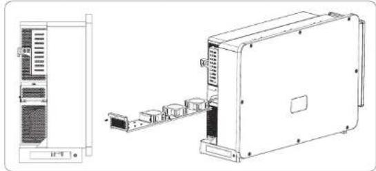
natural_image
Technical line drawing of an electronic device with front panel and internal components (no text or symbols)- Safety checks
Safety checks should be performed at least every 12 months by manufacturer's qualified person who has adequate training, knowledge, and practical experience
to perform these tests. The data should be recorded in an equipment log. If the device is not functioning properly or fails any of test, the device has to be repaired. For safety check details, refer to this manual, section 2 Safety instruction and EC Directives.
- Maintain periodically
Only qualified person may perform the following works.
During the process of using the inverter, the manage person shall examine and maintain the machine regularly. The concrete operations are follow.
1) Check that if the cooling fins on the rear of inverter are covered by dirts, and the machine should be cleaned and absorbed dust when necessary. This work shall be check from time to time.
2) Check that if the indicators of the inverter are in normal state, check if the display of the inverter (if it has screen) is normal. This check should be performed at least every 6 months.
3) Check that if the input and output wires are damaged or aged. This check should be performed at least every 6 months.
4) Check whether the ground terminal and ground cable are securely connected and all terminals and ports are properly sealed. This check should be performed at least every 6 months.
5) You should get the inverter panels cleaned and their safety checked at least every 6 months.
11 Decommissioning
11.1 Dismantling the Inverter
- Switch off the DC and AC switch/breaker and disconnect the inverter
*from DC Input and AC output.
* Wait for 5 minutes for de-energizing.
* Disconnect communication and optional connection wirings.
* Remove the inverter from the bracket.
Remove the bracket if necessary.

WARNING!
Before dismantling the inverter, please be sure to disconnect the DC switch, and then unplug the PV and AC cables, otherwise it will lead to an electric shock hazard.
11.2 Packaging
If possible, please pack the inverter with the original packaging.
If it is no longer available, you can also use an equivalent carton that meets the following requirements.
• Suitable for loads more than 80 kg.
- With handle.
- Can be fully closed.
11.3 Storage and Transportation
Store the inverter in dry place where ambient temperatures are always between
-25°C - +60°C. Take care of the inverter during the storage and transportation, keep less than 4 cartons in one stack.
When the inverter or other related components need to be disposed. Have it carried out according to local waste handling regulations. Please be sure to deliver wasted inverters and packing materials to certain site, which can assist relevant department to dispose and recycle.
11.4 Disposing of the inverter
If the inverter service life expires, dispose of it according to the local disposal rules for electrical equipment waste.
12 Disclaimer
The inverters shall be transported, used and operated under restricted conditions. We will not provide any service, technical support or compensation in case of the following circumstances, including but not limited to:
- The inverter is damaged by force majeure (such as earthquake, flooding, thunderstorm, lighting, fire hazard, volcanic eruption, etc.);
• The inverter's warranty is expired, but not extended; - The inverter's SN, warranty card or invoice cannot be provided;
- The inverter is damaged by man-made cause;
• The inverter is used or operated against any items in local policy; - The installation, configuration and commissioning of the inverter doesn't meet the requirements mentioned in this manual;
• The inverter is installed, refitted or operated in improper ways; - The inverter is installed, operated under improper environment or electrical condition;
- The inverter is changed, updated or disassembled on hardware or software without authority from us;
• The communication protocol from other illegal channels is used; and - The monitoring or control system is used without authority from us. SoleX reserves the right for the final explanation.
Warranty Registration Form

For Customer (Compulsory)
Name Country
Phone Number Email
Address
State Zip Code
Product Serial Number
Date of Commissioning
Installation Company Name ____
Installer Name ____ Electrician License No. ____
For Installer
Module (If Any)
Module Brand
Module Size(W)
Number of String Number of Panel Per String
Battery ( If Any )
Battery Type ____
Brand
Number of Battery Attached
Date of Delivery Signature
Please visit our warranty website: https://www.solaxcloud.com/#/warranty to complete the online warranty registration or use your mobile phone to scan the QR code to register.
For more detailed warranty terms, please visit SolaX official website: www.solaxpower.com to check it.
614.00002.07
PLEASE REGISTER THE WARRANTY IMMEDIATELY AFTER INSTALLATION! GET YOUR WARRANTY CERTIFICATE FROM SOLAX ! KEEP YOUR INVERTER ONLINE & WIN SOLAX POINTS!
1
Open your camera app and point your device at the QR code

2
Wait for the camera to recognize the QR code

3
Click banner or notification when it appears on the screen

4
Warranty registration page will be loaded automatically