PAC12337 - Klima uređaj Premium - Besplatni korisnički priručnik
Pronađite besplatno priručnik za uređaj PAC12337 Premium u PDF formatu.

Pitanja korisnika o PAC12337 Premium
0 pitanje o ovom uređaju. Odgovorite na one koje znate ili postavite svoje.
Postavi novo pitanje o ovom uređaju
Preuzmite upute za vaš Klima uređaj u PDF formatu besplatno! Pronađite svoj priručnik PAC12337 - Premium i uzmite svoju elektroničku napravu natrag u ruke. Na ovoj stranici objavljeni su svi dokumenti potrebni za korištenje vaše naprave. PAC12337 marke Premium.
KORISNIČKI PRIRUČNIK PAC12337 Premium
Premium
PREMIUM ON-OFF SERIES
Model: PAC9137 PAC9337
PAC12137 PAC12337
PAC18337
PAC24337
natural_image
Line drawing of a cylindrical air conditioner unit with a digital display showing 26 seconds (no text or symbols on the device itself)
natural_image
Illustration of a circuit board pattern with various electronic components (no text or symbols)Table of Contents
1. Safety Precautions....1
- In case of Accidents or Emergency
- Pre-Installation and Installation
- Operation and Maintenance
2. Specifications 3
- Model Reference
- Electrical Wiring Diagrams
3. Product Features 9
- Operation Modes and Functions
4. Maintenance and Disassembly 13
- Maintenance
- Disassembly
5. Troubleshooting....54
- Safety Caution
- General Troubleshooting
- Error Diagnosis and Troubleshooting Without Error Code
- Quick Maintenance by Error Code
- Troubleshooting by Error Code
Appendix 73
i) Temperature Sensor Resistance Value Table for T1,T2,T3 and T4 (°C - K)
ii) Pressure On Service Port
Safety Precautions
Contents
- In Case of Accidents or Emergency 2
- Pre-Installation....2
- Operation and Maintenance....2
To prevent personal injury, or property or unit damage, adhere to all precautionary measures and instructions outlined in this manual. Before servicing a unit, refer to this service manual and its relevant sections.
Failure to adhere to all precautionary measures listed in this section may result in personal injury, damage to the unit or to property, or in extreme cases, death.

WARNING indicates a potentially hazardous situation which if not avoided could result in serious personal injury, or death.

CAUTION indicates a potentially hazardous situation which if not avoided could result in minor or moderate personal injury, or unit damage.
1. In case of Accidents or Emergency

WARNING
- If a gas leak is suspected, immediately turn off the gas and ventilate the area if a gas leak is suspected before turning the unit on.
- If strange sounds or smoke is detected from the unit, turn the breaker off and disconnect the power supply cable.
- If the unit comes into contact with liquid, contact an authorized service center.
- If liquid from the batteries makes contact with skin or clothing, immediately rinse or wash the area well with clean water.
- Do not insert hands or other objects into the air inlet or outlet while the unit is plugged in.
• Do not operate the unit with wet hands. - Do not use a remote controller that has previously been exposed to battery damage or battery leakage.

CAUTION
- Clean and ventilate the unit at regular intervals when operating it near a stove or near similar devices.
- Do not use the unit during severe weather conditions. If possible, remove the product from the window before such occurrences.
2. Pre-Installation and Installation

WARNING
• Use this unit only on a dedicated circuit.
- Damage to the installation area could cause the unit to fall, potentially resulting in personal injury, property damage, or product failure.
- Only qualified personnel should disassemble, install, remove, or repair the unit.
- Only a qualified electrician should perform electrical work. For more information, contact your dealer, seller, or an authorized Midea service center.

CAUTION
- While unpacking be careful of sharp edges around the unit as well as the edges of the fins on the condenser and evaporator.
3. Operation and Maintenance

WARNING
• Do not use defective or under-rated circuit breakers.
- Ensure the unit is properly grounded and that a dedicated circuit and breaker are installed.
- Do not modify or extend the power cable. Ensure the power cable is secure and not damaged during operation.
- Do not unplug the power supply plug during operation.
- Do not store or use flammable materials near the unit.
- Do not open the inlet grill of the unit during operation.
- Do not touch the electrostatic filter if the unit is equipped with one.
• Do not block the inlet or outlet of air flow to the unit.
- Do not use harsh detergents, solvents, or similar items to clean the unit. Use a soft cloth for cleaning.
- Do not touch the metal parts of the unit when removing the air filter as they are very sharp.
- Do not step on or place anything on the unit or outdoor units.
• Do not drink water drained from the unit
- Avoid direct skin contact with water drained from the unit.
- Use a firm stool or step ladder according to manufacturer procedures when cleaning or maintaining the unit.

CAUTION
- Do not install or operate the unit for an extended period of time in areas of high humidity or in an environment directly exposing it to sea wind or salt spray.
- Do not install the unit on a defective or damaged installation stand, or in an unsecure location.
• Ensure the unit is installed at a level position - Do not install the unit where noise or air discharge created by the outdoor unit will negatively impact the environment or nearby residences.
- Do not expose skin directly to the air discharged by the unit for prolonged periods of time.
- Ensure the unit operates in areas water or other liquids.
- Ensure the drain hose is installed correctly to ensure proper water drainage.
- When lifting or transporting the unit, it is recommended that two or more people are used for this task.
- When the unit is not to be used for an extended time, disconnect the power supply or turn off the breaker.
Specifications
Contents
- Model Reference......4
- Electrical Wiring Diagrams....5
2.1 Indoor Unit....5
2.2 Outdoor Unit....7
1. Model Reference
Refer to the following table to determine the specific indoor and outdoor unit model number of your purchased equipment.
| Specifications |
| Indoor Unit Model | Outdoor Unit Model | Capacity (Btu) | Power Supply |
| PAC9137 | PAC9137 | 9k | 115V~, 60Hz, 1Phase |
| PAC12137 | PAC12137 | 12k | |
| PAC9337 | PAC9337 | 9k | 220-230V~, 60Hz, 1Phase |
| PAC12337 | PAC12337 | 12k | |
| PAC18337 | PAC18337 | 18k | |
| PAC24337 | PAC24337 | 24k |
2. Electrical Wiring Diagrams
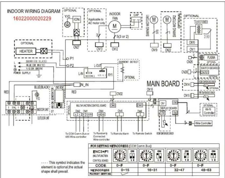
2.1 Indoor unit
| Abbreviation | Paraphrase |
| Y/G | Yellow-Green Conductor |
| ION | Positive and Negative Ion Generator |
| CAP | Capacitor |
| PLASMA | Electronic Dust Collector |
| X Y E | To Central Controller or 485 wired Controller |
| L | LIVE |
| N | NEUTRAL |
| Heater | The Electric Heating Belt of Indoor Unit |
| T1 | Indoor Room Temperature |
| T2 | Coil Temperature of Indoor Heat Exchanger Middle |
PAC9137; PAC12137; PAC9337; PAC12337; PAC18337
flowchart
graph TD
    subgraph_INDOOR_WIRING_DIAGRAM["INDOOR WIRING DIAGRAM 16022000020229"]
        A["HEATER"] --> B["P1"]
        A --> C["P2"]
        B --> D["L-IN"]
        C --> E["L-OUT"]
        D --> F["CY1"]
        E --> G["CY1"]
        F --> H["CURRENT DETECT"]
        G --> I["OPTIONAL"]
        H --> J["OPTIONAL"]
        I --> K["MAIN BOARD"]
        J --> L["MAIN BOARD"]
        K --> M["MAIN BOARD"]
        L --> N["MAIN BOARD"]
        M --> O["MAIN BOARD"]
        N --> P["MAIN BOARD"]
        O --> Q["MAIN BOARD"]
        P --> R["MAIN BOARD"]
        S["POWER SUPPLY"] --> T["BROWN (OR BLACK)"]
        T --> U["BLE (OR WHITE)"]
        U --> V["Y/G (OR GREEN)"]
        T --> W["BLE(BLACK)"]
        W --> X["TO ALLON GENERATOR"]
        X --> Y["TO CCM Comm.Bus or 485 Wire-controller"]
        Y --> Z["TO CCM Comm.Bus or 485 Wire-controller"]
        Z --> AA["TO CCM Comm.Bus or 485 Wire-controller"]
        AA --> AB["TO CCM Comm.Bus or 485 Wire-controller"]
        AB --> AC["TO CCM Comm.Bus or 485 Wire-controller"]
        AC --> AD["TO CCM Comm.Bus or 485 Wire-controller"]
        AD --> AE["TO CCM Comm.Bus or 485 Wire-controller"]
        AE --> AF["TO CCM Comm.Bus or 485 Wire-controller"]
        AF --> AG["TO CCM Comm.Bus or 485 Wire-controller"]
        AG --> AH["TO CCM Comm.Bus or 485 Wire-controller"]
        AH --> AI["TO CCM Comm.Bus or 485 Wire-controller"]
        AI --> AJ["TO CCM Comm.Bus or 485 Wire-controller"]
        AJ --> AK["TO CCM Comm.Bus or 485 Wire-controller"]
        AK --> AL["TO CCM Comm.Bus or 485 Wire-controller"]
        AL --> AM["TO CCM Comm.Bus or 485 Wire-controller"]
        AM --> AN["TO CCM Comm.Bus or 485 Wire-controller"]
        AN --> AO["TO CCM Comm.Bus or 485 Wire-controller"]
        AO --> AP["TO CCM Comm.Bus or 485 Wire-controller"]
        AP --> AQ["TO CCM Comm.Bus or 485 Wire-controller"]
        AQ --> AR["TO CCM Comm.Bus or 485 Wire-controller"]
        AR --> AS["TO CCM Comm.Bus or 485 Wire-controller"]
        AS --> AT["TO CCM Comm.Bus or 485 Wire-controller"]
        AT --> AU["TO CCM Comm.Bus or 485 Wire-controller"]
        AU --> AV["TO CCM Comm.Bus or 485 Wire-controller"]
        AV --> AW["TO CCM Comm.Bus or 485 Wire-controller"]
        AW --> AX["TO CCM Comm.Bus or 485 Wire-controller"]
        AX --> AY["TO CCM Comm.Bus or 485 Wire-controller"]
        AY --> AZ["TO CCM Comm.Bus or 485 Wire-controller"]
        AZ --> BA["TO CCM Comm.Bus or 485 Wire-controller"]
        BA --> BB["TO CCM Comm.Bus or 485 Wire-controller"]
        BB --> BC["TO CCM Comm.Bus or 485 Wire-controller"]
        BC --> BD["TO CCM Comm.Bus or 485 Wire-controller"]
        BD --> BE["TO CCM Comm.Bus or 485 Wire-controller"]
        BE --> BF["TO CCM Comm.Bus or 485 Wire-controller"]
        BF --> BG["TO CCM Comm.Bus or 485 Wire-controller"]
        BG --> BH["TO CCM Comm.Bus or 485 Wire-controller"]
        BH --> BI["TO CCM Comm.Bus or 485 Wire-controller"]
        BI --> BJ["TO CCM Comm.Bus or 485 Wire-controller"]
        BJ --> BK["TO CCM Comm.Bus or 485 Wire-controller"]
        BK --> BL["TO CCM Comm.Bus or 485 Wire-controller"]
        BL --> BM["TO CCM Comm.Bus or 485 Wire-controller"]
        BM --> BN["TO CCM Comm.Bus or 485 Wire-controller"]
        BN --> BO["TO CCM Comm.Bus or 485 Wire-controller"]
        BO --> BP["TO CCM Comm.Bus or 485 Wire-controller"]
        BP --> BQ["TO CCM Comm.Bus or 485 Wire-controller"]
        BQ --> BR["TO CCM Comm.Bus or 485 Wire-controller"]
        BR --> BS["TO CCM Comm.Bus or 485 Wire-controller"]
        BS --> BT["TO CCM Comm.Bus or 485 Wire-controller"]
        BT --> BU["TO CCM Comm.Bus or 485 Wire-controller"]
        BU --> BV["TO CCM Comm.Bus or 485 Wire-controller"]
        BV --> BW["TO CCM Comm.Bus or 485 Wire-controller"]
        BW --> BX["TO CCM Comm.Bus or 485 Wire-controller"]
        BX --> BY["TO CCM Comm.Bus or 485 Wire-controller"]
        BY --> BZ["TO CCM Comm.Bus or 485 Wire-controller"]
        BZ --> CA["TO CCM Comm.Bus or 485 Wire-controller"]
        CA --> CB["TO CCM Comm.Bus or 485 Wire-controller"]
        CB --> CC["TO CCM Comm.Bus or 485 Wire-controller"]
        CC --> CD["TO CCM Comm.Bus or 485 Wire-controller"]
        CD --> CE["TO CCM Comm.Bus or 485 Wire-controller"]
        CE --> CF["TO CCM Comm.Bus or 485 Wire-controller"]
        CF --> CG["TO CCM Comm.Bus or 485 Wire-controller"]
        CG --> CH["TO CCM Comm.Bus or 485 Wire-controller"]
        CH --> CI["TO CCM Comm.Bus or 485 Wire-controller"]
        CI --> CJ["TO CCM Comm.Bus or 485 Wire-controller"]
        CJ --> CK["TO CCM Comm.Bus or 485 Wire-controller"]
        CK --> CL["TO CCM Comm.Bus or 485 Wire-controller"]
        CL --> CM["TO CCM Comm.Bus or 485 Wire-controller"]
        CM --> CN1
    end
PAC24337

text_image
INDOOR WIRING DIAGRAM 16022000022180 OPTIONAL Y/G ION CN27 P1 P2 OPTIONAL Applicable to AC motor only 3/ CN13 CN12 CAP 5(3 or 2) INDOOR FAN M SWING MOTOR1 M SWING MOTOR2 CN10 CN11 OPTIONAL TRANSFORMER 2(4) CN26 PLASMA OPTIONAL BLUE(BLACK) YELLOW Y/G L-IN RY1 N_IN CN31 MAIN BOARD CN29 CN703 OPTIONAL SWITCH BOARD CN15 INTUUM BLOOD SENSOR CN14 ON TEMPER ON SMO2 OPTIONAL MULTI-FUNCTION CONTROL BOARD CNV5 CNV6 CNV8 CNV9 ON DISPLAY BOARD CNV1 ON OPTIONAL W-L-FI Controller OPTIONAL TO CCM Comm.Bus or 485 Wire-controller To Randomly Connected Wire-controller To Remote Alarm To Remote Switch TO CCM Comm.Bus or 485 Wire-controller FOR SETTING NETADDRESS (CCM Comm. Bus) ENC3+F1 (MULTI-FUNCTION CONTROL BOARD) CODE 0~F ON 0~F ON 0~F ON ON NETADDRESS 0~15 16~31 32~47 48~63 FACTORY SETTING ✓2.2 Outdoor Unit
| Abbreviation | Paraphrase |
| 4-WAY | Gas Valve Assembly/4-WAY VALVE |
| CT | AC Current Detector |
| COMP | Compressor |
| L-PRO | Low Pressure Switch |
| H-PRO | High Pressure Switch |
| T3, RT3 | Coil Temperature of Condenser |
| T4 | Outdoor Ambient Temperature |
| OLP | Overload Relay |
| CAP1 | Compressor Capacitor |
| CAP2 | Outdoor Fan Capacitor |
| UNIT1 | Outdoor Control PCB |
| KM1 | AC Contactor |
| TRANS | Transformer |
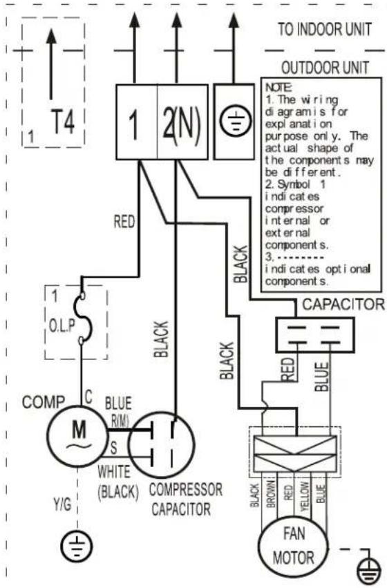
PAC9137, PAC12137, PAC9337, PAC12337

flowchart
graph TD
    A["TO INDOOR UNIT"] --> B["1"]
    A --> C["2(N)"]
    D["Pressure switch port"] --> E["BLACK"]
    E --> F["OVERLOAD RELAY (INTERNAL/ EXTERNAL DEPENDING ON MODELS)"]
    F --> G["C"]
    G --> H["COMP R(M)"]
    H --> I["S"]
    I --> J["Y/G"]
    K["OUTDOOR UNIT"] --> L["FAN MOTOR"]
    L --> M["BLUX"]
    M --> N["RED CAPACITOR"]
    N --> O["RED"]
    O --> P["BLUE"]
    Q["Black"] --> R["RED CAPACITOR"]
    S["Black"] --> T["RED CAPACITOR"]
    U["Blue"] --> V["FAN MOTOR"]
    W["This symbol indicates the element is optional, the actual shape shall be prevail."]
PAC18337
PAC24337
text_image
TO INDOOR UNIT OUTDOOR UNIT NOTE: 1. The wiring diagramis for explanation purpose only. The actual shape of the components may be different. 2. Symbol 1 indicates compressor internal or external component s. 3. - indicates optional component s. COMP C BLUE R(M) S WHITE (BLACK) COMPRESSOR CAPACITOR Y/G BLACK BLACK CAPACITOR RED RED BLUE FAN MOTOR BROWN RED YELLOW BLUE
text_image
FAN MOTOR BLACK SROWN RED YELLOW BLUE 1/2 1 2 3 TRANS1 CN1 CN2 CN8 CN6 CN3 UN I T 1 CN15 CN16 CN4 H-PRO L-PRO H-PRO L-PRO 4 H-PRO CAP2 RT3 XP1 XS1 CT MINI KM1 A1 A2 BLACK RED RED R COMP WHITE (or BLACK) O LP S Y/G R 1/2 1/2 2/4 2/4 1/2 1/2 2/4 2/4 2/4 2/4 2/4 2/4 2/4 2/4 2/4 2/4 2/4 2/4 2/4 2/4 2/4 2/4 2/4 2/4 2/4 2/4 2/4 2/4 2/4 2/4 2/4 2/8 PTCR OPTION 2 Black PTCR Black WHITE TO INDOOR UNIT POWER SUPPLY Y/G Notes: Symbol symbolWIRING DIAGRAM (OUTDOOR UNIT)
| CODE | PART NAME |
| UNIT1 | OUTDOOR CONTROL PCB |
| COMP | COMPRESSOR |
| CAP1 | COMPRESSOR CAPACITOR |
| FAN2 | OUTDOOR FAN |
| CAP2 | OUTDOOR FAN CAPACITOR |
| XT1 | 5-WAY TERMINAL |
| XT2 | MIDDLE TERMINAL |
| KM1 | AC CONTACTOR |
| CT | CURRENT INDUCTOR |
| TRANS1 | TRANSFORMER |
| CN1-CN11 | PCB SOCKETS |
| XP1, XS1 | CONNECTORS |
| RT3 | PIPE TEMPERATURE SENSOR |
Symbol 1: indicates compressor internal or external components. symbol 2&3&4: indicates the element is optional, the actual shape shall be prevalent.
Product Features
Contents
1. Operation Modes and Functions....10
1.1 Abbreviation....10
1.2 Safety Features....10
1.3 Digital Display....10
1.4 Fan Mode....11
1.5 Cooling Mode....11
1.6 Auto-mode....11
1.7 Drying Mode 11
1.8 Forced Operation Function 11
1.9 Auto-Restart Function....11
1.10 Refrigerant Leakage Detection....12
1.11 Self Clean(Optional)....12
1.12 Follow Me(Optional)....12
1.13 Information Inquiry....12
1. Operation Modes and Functions
1.1 Abbreviation
Unit element abbreviations
| Abbreviation | Element |
| T1 | Indoor room temperature |
| T2 | Coil temperature of evaporator |
| T3 | Coil temperature of condenser |
| T4 | Outdoor ambient temperature |
1.2 Safety Features
Compressor three-minute delay at restart
Compressor functions are delayed for up to one minute upon the first startup of the unit, and are delayed for up to three minutes upon subsequent unit restarts.
Zero crossing detection error protection
If AC can not detect zero crossing signal for 4 minutes or the zero crossing signal time interval is not correct, the unit will stop and the LED will display the failure. The correct zero crossing signal time interval should be between 6-13ms.
Automatic shutoff based on fan speed
If the indoor fan speed registers below 300RPM for 2 minutes, the unit ceases operation and the corresponding error code is displayed on the indoor unit.
Current protection
The current exceeds setting value for certain time, the compressor and outdoor fan will shut off.
Indoor fan delayed operation
- When the unit starts, the louver is automatically activated and the indoor fan will operate after a period of 4 seconds.
- If the unit is in heating mode, the indoor fan is regulated by the anti-cold wind function.
Sensor redundancy and automatic shutoff
If one temperature sensor malfunctions, the air conditioner ceases operation.
Refrigerant leakage detection
This function is active only when cooling mode is selected. It will detect if the compressor is being damaged by refrigerant leakage or by compressor overload. This is measured using the coil temperature of evaporator T2 when the compressor is in operation.
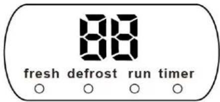
1.3 Digital Display
Unit display functions
text_image
88 fresh defrost run timer ○ ○ ○ ○| Function | Display |
| Temperature | Set temperature value |
| Temperature (fan and Drying mode) | Room temperature |
| Activation of Timer ON, Fresh, Swing, Turbo, or Silent | ON(3s) |
| Cancellation of Timer OFF, Fresh, Swing, Turbo, or Silent | OF(3s) |
| Defrost | dF |
| Warming in heating mode | cF |
| Self-clean (available on select units only) | SC |
| Heating in room tempurature under 8°C | FP |
1.4 Fan Mode
When fan mode is activated:
• The outdoor fan and compressor are stopped.
- Temperature control is disabled and no temperature setting is displayed.
- The indoor fan speed can be set to high, medium, low, or auto.
- The louver operations are identical to those in cooling mode.
- Auto fan: In fan-only mode, AC operates the same as auto fan in cooling mode with the temperature set at 24°C.
1.5 Cooling Mode
1.5.1 Compressor Control
When indoor room temp. T1 is lower than setting value, the compressor and outdoor fan will shut off.
1.5.2 Indoor Fan Control
In cooling mode, the indoor fan operates continuously. The fan speed can be set to high, medium, low, or auto.
1.5.3 Outdoor Fan Control
The On-off outdoor units have single fan speed. The outdoor fan will run following the compressor except when AC is in evaporator high temperature protection in heating mode, condenser high temperature protection in cooling mode, defrosting mode and the current protection.
1.5.4 Evaporator Temperature Protection
When evaporator temperature drops below a configured value, the compressor and outdoor fan ceases operations.
1.6 Auto-mode
- This mode can be selected with the remote controller.
- In auto mode, the machine selects cooling, heating, or fan-only mode on the basis of T ( T = T1 - Ts ).
| ΔT | Running mode |
| ΔT>2°C | Cooling |
| -3°C≤ΔT≤2°C | Fan-only |
| ΔT<-3°C | Heating* |
Heating*: In auto mode, cooling only models run the fan
- AC will run in auto mode in the below cases:
- Pressing the forced auto button.
- If AC is off, it will run in auto mode when the timer on function is active.
• After setting the mode, AC will run in auto mode if the compressor keeps not running for certain time.
1.7 Drying mode
- The compressor is cycled running with 10 minutes on and then 5 minutes off. The indoor fan will keep running at low speed.
- In drying mode, if room temperature is lower than 10°C, the compressor will stop and not resume until room temperature exceeds 13°C.
- The evaporator anti-freezing protection is the same as that in cooling mode.
1.8 Forced operation function
- Forced cooling mode:
The compressor and outdoor fan continue to run and the indoor fan runs at low speed. After running for 30 minutes, the AC will switch to auto mode with a preset temperature of 24°C.
- Forced auto mode:
Forced auto mode operates the same as normal auto mode with a preset temperature of 24^ C.
- The unit exits forced operation when it receives the following signals:
- Switch on
- Switch off
- Timer on
- Timer off
- Changes in:
- mode
- fan speed
- sleeping mode
1.9 Auto-Restart function
- The indoor unit has an auto-restart module that allows the unit to restart automatically. The module automatically stores the current settings (not including the swing setting) and, in the case of a sudden power failure, will restore those setting automatically within 3 minutes after power returns.
- If the unit was in forced cooling mode, it will run in this mode for 30 minutes and turn to auto mode with temperature set to 24^ .
- If there is a power failure while the unit is running, the compressor starts 3 minutes after the unit restarts. If the unit was already off before the power failure, the compressor starts 20 seconds after the unit restarts.
1.10 Refrigerant Leakage Detection
- With this new technology, the display area will show "EC" when the outdoor unit detects refrigerant leakage.
- When compressor is active, the value of the Coil temperature of evaporator T2 has no change or very little change.
1.11 Self clean(Optional)
- If you press "Self Clean" when the unit is in cooling or drying mode:
- For cooling models, the indoor unit will run in low fan mode for a certain time, then ceases operation.
- For heat pump models, the indoor unit will run in fan-only mode, then low heat, and finally in fan-only mode.
- Self Clean keeps the indoor unit dry and prevents mold growth.
1.12 Follow me(Optional)
- If you press "Follow Me" on the remote, the indoor unit will beep. This indicates the follow me function is active.
- Once active, the remote control will send a signal
every 3 minutes, with no beeps. The unit automatically sets the temperature according to the measurements from the remote control.
- The unit will only change modes if the information from the remote control makes it necessary, not from the unit's temperature setting.
- If the unit does not receive a signal for 7 minutes or you press "Follow Me," the function turns off. The unit regulates temperature based on its own sensor and settings.
1.13 Information Inquiry
• To enter information inquiry status, complete the following procedure within ten seconds:
- Press LED 3 times.
- Press SWING 3 times.
- If you are successful, you will hear beeps for two seconds.
- Use the LED and SWING buttons to cycle through information displayed.
- Pressing LED will display the next code in the sequence. Pressing SWING will show the previous.
- The following table shows information codes. The screen will display this code for two seconds, then the information for 25 seconds.
| Displayed code | Explanation | Displayed value | Meaning | Additional Notes |
| TI | Room temperature | -14—70 | -14—70 | 1. All displayed temperatures use actual values.2. All temperatures are displayed in °C regardless of remote used.3. If the actual value exceeds the range, it will display the maximum value or minimum value. |
| T2 | Indoor coil temperature | |||
| T3 | Outdoor coil temperature |
Maintenance and Disassembly
Contents
1. Maintenance .... 14
1.1 First Time Installation Check 14
1.2 Refrigerant Recharge....16
1.3 Re-Installation 17
1.3.1 Indoor Unit 17
1.3.2 Outdoor Unit 19
2. Disassembly 21
2.1 Indoor Unit....21
2.2 Outdoor Unit....33
1. Maintenance
1.1 First Time Installation Check
Air and moisture trapped in the refrigerant system affects the performance of the air conditioner by:
- Increasing pressure in the system.
- Increasing the operating current.
• Decreasing the cooling or heating efficiency. - Congesting the capillary tubing due to ice build-up in the refrigerant circuit.
• Corroding the refrigerant system.
To prevent air and moisture from affecting the air conditioner's performance, the indoor unit, as well as the pipes between the indoor and outdoor unit, must be leak tested and evacuated.
Leak test (soap water method)
Use a soft brush to apply soapy water or a neutral liquid detergent onto the indoor unit connections and outdoor unit connections. If there is gas leakage, bubbles will form on the connection.
Air purging with vacuum pump

flowchart
graph TD
    A["Interior unit"] --> B["(Liquid side)"]
    A --> C["(Gas side)"]
    D["Vacuum pump"] --> E["Vacuum pump"]
    F["Handle Lo"] --> G["Lo"]
    G --> H["Charge hose"]
    I["Handle Hi"] --> J["Hi"]
    K["Pressure gauge"] --> L["Lo"]
    M["Handle Lo"] --> N["Charge hose"]
    O["Compound meter -0.1MPa"] --> P["Lo"]
    Q["Two-way valve Close"] --> R["Close"]
    S["Three-way valve Close"] --> T["Close"]
    U["Manifold valve"] --> V["Lo"]
    W["(Outdoor unit)"] --> X["(Indoor unit)"]
    Y["Vacuum pump"] --> Z["Vacuum pump"]
Procedure:
- Tighten the flare nuts of the indoor and outdoor units, and confirm that both the 2- and 3-way valves are closed.
- Connect the charge hose with the push pin of Handle Lo to the gas service port of the 3-way valve.
- Connect another charge hose to the vacuum pump.
- Fully open the Handle Lo manifold valve.
- Using the vacuum pump, evacuate the system for 30 minutes.
a. Check whether the compound meter indicates -0.1 MPa (14.5 Psi).
- If the meter does not indicate -0.1 MPa (14.5 Psi) after 30 minutes, continue evacuating for an additional 20 minutes.
- If the pressure does not achieve -0.1 MPa
(14.5 Psi) after 50 minutes, check for leakage.
- If the pressure successfully reaches -0.1 MPa (14.5 Psi), fully close the Handle Lo valve, then cease vacuum pump operations.
b. Wait for 5 minutes then check whether the gauge needle moves after turning off the vacuum pump. If the gauge needle moves backward, check wether there is gas leakage.
- Loosen the flare nut of the 3-way valve for 6 or 7 seconds and then tighten the flare nut again.
a. Confirm the pressure display in the pressure indicator is slightly higher than the atmospheric pressure.
b. Remove the charge hose from the 3-way valve.
- Fully open the 2- and 3-way valves and tighten the cap of the 2- and 3-way valves.
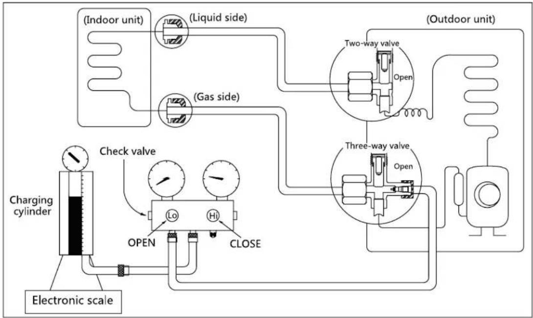
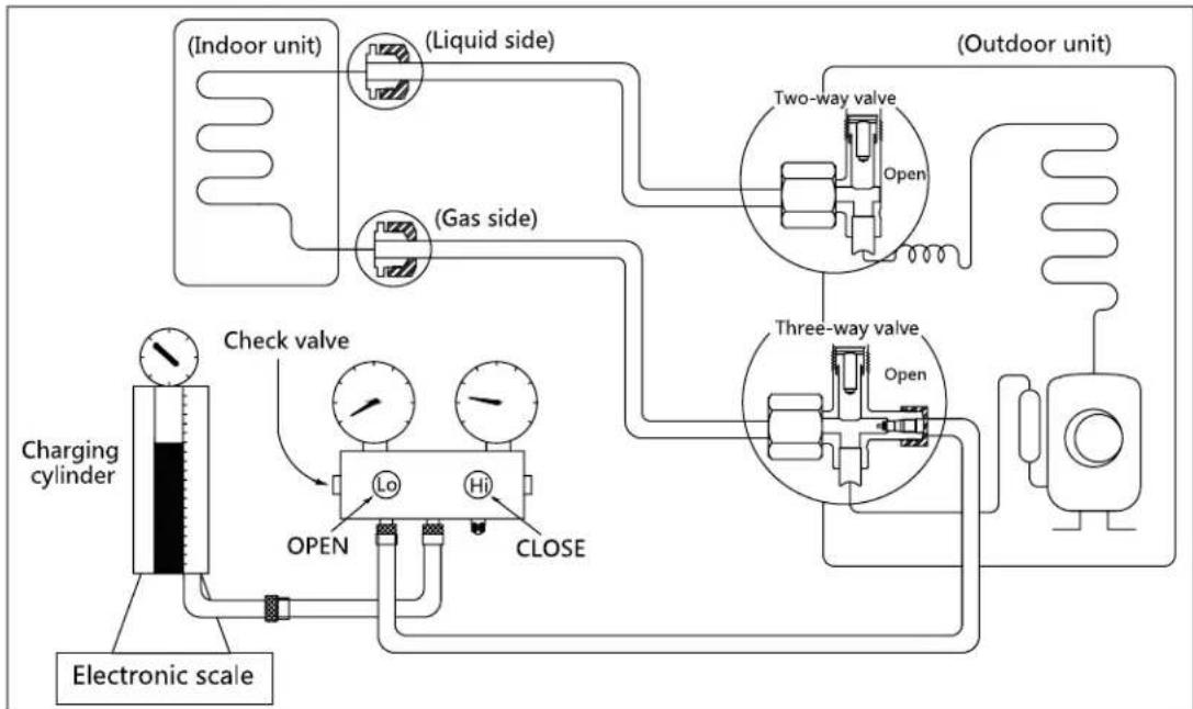
1.2 Refrigerant Recharge
flowchart
graph TD
    A["Electronic scale"] --> B["Charging cylinder"]
    B --> C["Check valve"]
    C --> D["Lo"]
    C --> E["Hi"]
    C --> F["CLOSE"]
    D --> G["Open"]
    E --> H["Open"]
    F --> I["Open"]
    J["(Indoor unit)"] --> K["(Liquid side)"]
    K --> L["(Gas side)"]
    L --> M["(Outdoor unit)"]
    M --> N["Two-way valve"]
    M --> O["Three-way valve"]
Maintenance and Disassembly
Prior to recharging the refrigerant, confirm the additional amount of refrigerant required using the following table:
| Models | Standard length | Max. elevation | Max. length | Additional refrigerant |
| 9k&12k | 5m (16.4ft) | 8m (26.2ft) | 20m (65.6ft) | 15g/m (0.16oz/ft) |
| 18k | 5m (16.4ft) | 10m (32.8ft) | 25m (82ft) | 15g/m (0.16oz/ft) |
| 24k | 5m (16.4ft) | 10m (32.8ft) | 25m (82ft) | 30g/m (0.32oz/ft) |
Procedure:
- Close both 2- and 3-way valves.
- Slightly connect the Handle Lo charge hose to the 3-way service port.
- Connect the charge hose to the valve at the bottom of the cylinder.
- If the refrigerant is R410A, invert the cylinder to ensure a complete liquid charge.
- Open the valve at the bottom of the cylinder for 5 seconds to purge the air in the charge hose, then fully tighten the charge hose with push pin Handle Lo to the service port of 3-way valve..
-
Place the charging cylinder onto an electronic scale and record the starting weight.
-
Fully open the Handle Lo manifold valve, 2- and 3-way valves.
- Operate the air conditioner in cooling mode to charge the system with liquid refrigerant.
- When the electronic scale displays the correct weight (refer to the gauge and the pressure of the low side to confirm), turn off the air conditioner, then disconnect the charge hose from the 3-way service port immediately..
- Mount the caps of service port and 2- and 3-way valves.
- Use a torque wrench to tighten the caps to a torque of 18 N.m.
- Check for gas leakage.
1.3 Re-Installation
1.3.1 Indoor Unit
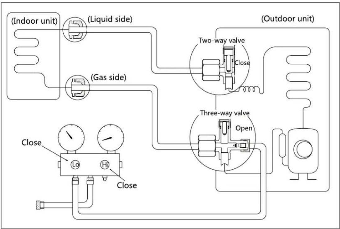
Collecting the refrigerant into the outdoor unit
flowchart
graph TD
    A["(Indoor unit)"] --> B["(Liquid side)"]
    B --> C["(Gas side)"]
    C --> D["Close"]
    D --> E["Lo"]
    D --> F["Hi"]
    D --> G["Close"]
    H["(Outdoor unit)"] --> I["Two-way valve"]
    I --> J["Close"]
    J --> K["Three-way valve"]
    K --> L["Open"]
    L --> M["Resistor"]
    M --> N["Resistor"]
    style A fill:#f9f,stroke:#333
    style H fill:#f9f,stroke:#333
    style I fill:#ccf,stroke:#333
    style K fill:#ccf,stroke:#333
    style L fill:#ccf,stroke:#333
    style M fill:#ccf,stroke:#333
Procedure:
- Confirm that the 2- and 3-way valves are opened.
- Connect the charge hose with the push pin of Handle Lo to the 3-way valve's gas service port.
- Open the Handle Lo manifold valve to purge air from the charge hose for 5 seconds and then close it quickly.
- Close the 2-way valve.
-
Operate the air conditioner in cooling mode. Cease operations when the gauge reaches 0.1 MPa (14.5 Psi).
-
Close the 3-way valve so that the gauge rests between 0.3 MPa (43.5 Psi) and 0.5 MPa (72.5 Psi).
- Disconnect the charge set and mount the caps of service port and 2- and 3-way valves.
- Use a torque wrench to tighten the caps to a torque of 18 N.m.
- Check for gas leakage.
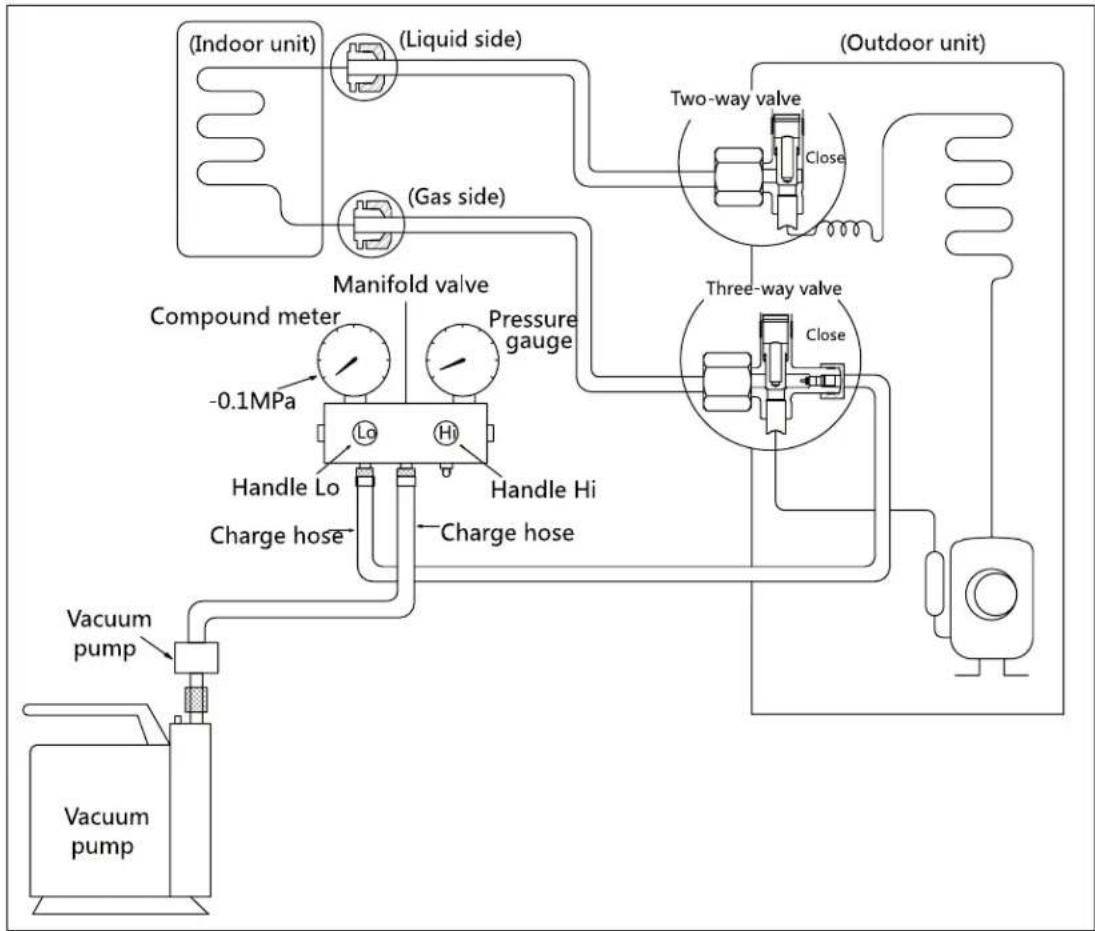
Air purging with vacuum pump
flowchart
graph TD
    A["(Indoor unit)"] --> B["(Liquid side)"]
    B --> C["(Gas side)"]
    C --> D["Manifold valve"]
    D --> E["Compound meter"]
    E --> F["-0.1MPa"]
    F --> G["Handle Lo"]
    G --> H["Charge hose"]
    H --> I["Vacuum pump"]
    I --> J["Vacuum pump"]
    D --> K["Pressure gauge"]
    K --> L["Handle Hi"]
    L --> M["Charge hose"]
    M --> N["Vacuum pump"]
    N --> O["Vacuum pump"]
    P["(Outdoor unit)"] --> Q["Two-way valve"]
    Q --> R["Close"]
    R --> S["Three-way valve"]
    S --> T["Close"]
    T --> U["Thermal transformer"]
    U --> V["Return to outdoor unit"]
Procedure:
- Tighten the flare nuts of the indoor and outdoor units, and confirm that both the 2- and 3-way valves are closed.
- Connect the charge hose with the push pin of Handle Lo to the gas service port of the 3-way valve.
- Connect another charge hose to the vacuum pump.
- Fully open the Handle Lo manifold valve.
- Using the vacuum pump, evacuate the system for 30 minutes.
a. Check whether the compound meter indicates -0.1 MPa (14.5 Psi).
- If the meter does not indicate -0.1 MPa (14.5 Psi) after 30 minutes, continue evacuating for an additional 20 minutes.
- If the pressure does not achieve -0.1 MPa (14.5
Psi) after 50 minutes, check for leakage.
- If the pressure successfully reaches -0.1 MPa (14.5 Psi), fully close the Handle Lo valve, then cease vacuum pump operations.
b. Wait for 5 minutes then check whether the gauge needle moves after turning off the vacuum pump. If the gauge needle moves backward, check wether there is gas leakage.
- Loosen the flare nut of the 3-way valve for 6 or 7 seconds and then tighten the flare nut again.
a. Confirm the pressure display in the pressure indicator is slightly higher than the atmospheric pressure.
b. Remove the charge hose from the 3-way valve.
- Fully open the 2- and 3-way valves and tighten the cap of the 2- and 3-way valves.
1.3.2 Outdoor Unit
Evacuation for the whole system

flowchart
graph TD
    A["Indoor unit"] --> B["(Liquid side)"]
    B --> C["(Gas side)"]
    C --> D["Two-way valve"]
    D --> E["Open"]
    D --> F["Three-way valve"]
    F --> G["Open"]
    H["Vacuum pump"] --> I["OPEN"]
    I --> J["Lip"]
    I --> K["Hi"]
    J --> L["CLOSE"]
    K --> L
    L --> M["Outdoor unit"]
Procedure:
- Confirm that the 2- and 3-way valves are opened.
- Connect the vacuum pump to the 3-way valve's service port.
- Evacuate the system for approximately one hour. Confirm that the compound meter indicates -0.1 MPa (14.5Psi).
-
Close the valve (Low side) on the charge set and turn off the vacuum pump.
-
Wait for 5 minutes then check whether the gauge needle moves after turning off the vacuum pump. If the gauge needle moves backward, check whether there is gas leakage.
- Disconnect the charge hose from the vacuum pump.
- Mount the caps of service port and 2- and 3-way valves.
- Use a torque wrench to tighten the caps to a torque of 18 N.m.
Refrigerant charging
flowchart
graph TD
    A["Electronic scale"] --> B["Charging cylinder"]
    B --> C["Check valve"]
    C --> D["OPEN"]
    D --> E["Lo"]
    D --> F["Hi"]
    D --> G["CLOSE"]
    B --> H["(Indoor unit)"]
    B --> I["(Liquid side)"]
    B --> J["(Gas side)"]
    B --> K["(Outdoor unit)"]
    K --> L["Two-way valve"]
    K --> M["Three-way valve"]
    L --> N["Open"]
    M --> O["Open"]
Procedure:
- Close both 2- and 3-way valves.
- Slightly connect the Handle Lo charge hose to the 3-way service port.
- Connect the charge hose to the valve at the bottom of the cylinder.
- If the refrigerant is R410A, invert the cylinder to ensure a complete liquid charge.
- Open the valve at the bottom of the cylinder for 5 seconds to purge the air in the charge hose, then fully tighten the charge hose with push pin Handle Lo to the service port of 3-way valve..
-
Place the charging cylinder onto an electronic scale and record the starting weight.
-
Fully open the Handle Lo manifold valve, 2- and 3-way valves.
- Operate the air conditioner in cooling mode to charge the system with liquid refrigerant.
- When the electronic scale displays the correct weight (refer to the gauge and the pressure of the low side to confirm), turn off the air conditioner, then disconnect the charge hose from the 3-way service port immediately..
- Mount the caps of service port and 2- and 3-way valves.
- Use a torque wrench to tighten the caps to a torque of 18 N.m.
- Check for gas leakage.
Note: 1. Mechanical connectors used indoors shall comply with local regulations.
2. When mechanical connectors are reused indoors, sealing parts shall be renewed. When flared joints are reused indoors, the flare part shall be re-fabricated.
2. Disassembly
2.1 Indoor unit
1. Front Panel
| Procedure | Illustration |
| 1) Hold the front panel by the tabs on the both sides and lift it (see CJ_AF_001). | 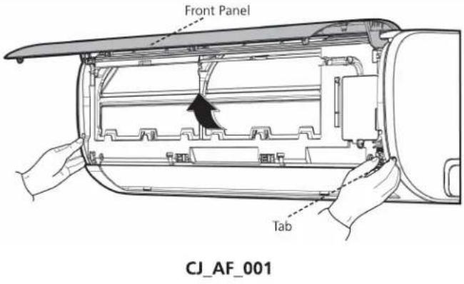 |
| 2) Push up the bottom of an air filter, and then pull it out downwards (see CJ_AF_002). |  |
Note: This section is for reference only. Actual unit appearance may vary.
| Procedure | Illustration |
| 3) Open the horizontal louver and push the hook towards left to open it (see CJ_AF_003). | 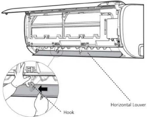 CJ_AF_003 CJ_AF_003 |
| 4) Bend the horizontal louver lightly by both hands to loosen the hooks, then remove the horizontal louver (see CJ_AF_004). | 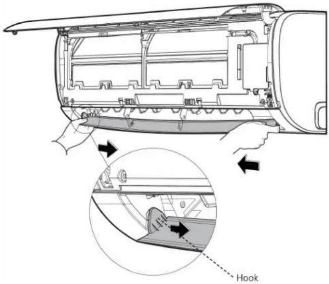 CJ_AF_004 CJ_AF_004 |
Note: This section is for reference only. Actual unit appearance may vary.
| Procedure | Illustration |
| 5) Remove 1 screw and then remove the electrical cover(see CJ_AF_005-1 and CJ_AF_005-2). | 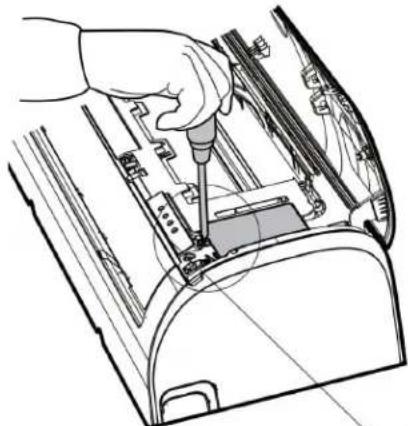 CJ_AF_005-1 CJ_AF_005-1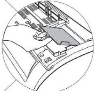 |
| 6) Disconnect the connector for display board(see CJ_AF_005-3). |  CJ_AF_005-3 CJ_AF_005-3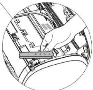 CJ_AF_005-4 CJ_AF_005-4 |
| 7) Remove the display board(see CJ_AF_005-4). |
Note: This section is for reference only. Actual unit appearance may vary.
| Procedure | Illustration |
| 8) Open the screw caps(2) and the remove the screws(see CJ_AF_006).9) Release the 4 hooks. | 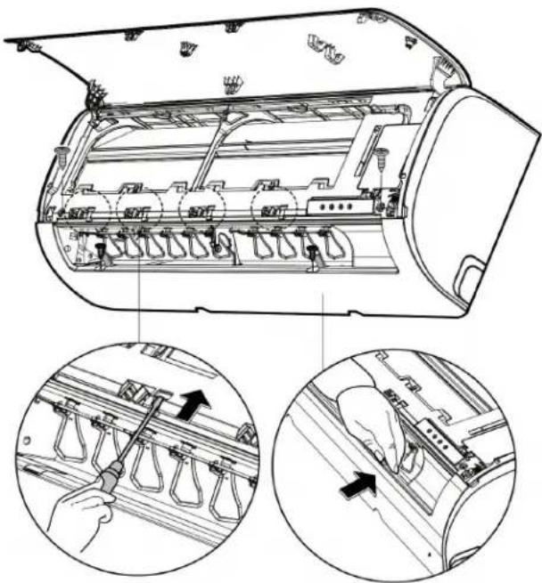 |
| 10)Release the seven hooks in the back (see CJ_AF_007). | 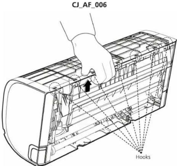 CJ_AF_007 CJ_AF_007 |
Note: This section is for reference only. Actual unit appearance may vary.
| Procedure | Illustration |
| 11)Pull out the panel frame while pushing the hook through a clearance between the panel frame and the heat exchanger (see CJ_AF_008). | 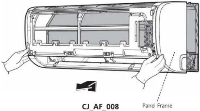 |
Note: This section is for reference only. Actual unit appearance may vary.
2. Electrical parts
Note: Remove the front panel (refer to 1. Front panel) before disassembling electrical parts.
| Procedure | Illustration |
| 1) Remove the fixing screw and then remove the cover of electronic box and the terminal cover (see CJ_AF_009). |  CJ_AF_009 CJ_AF_009 |
| 2) Pull out the room temperature sensor (T1) and the coil temperature sensor (T2) (see CJ_AF_010). | 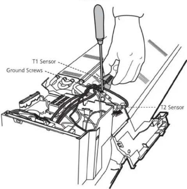 |
| 3) Remove the two screws used for the ground connection (see CJ_AF_010). | CJ_AF_010 |
Note: This section is for reference only. Actual unit appearance may vary.
| Procedure | Illustration |
| 4) Remove the fixing screw (see CJ_AF_011-1).5) Pull out the Electrical control box along the direction indicated in right image. to remove it (see CJ_AF_011-2).6) Disconnect the wires. Then remove the electronic main board (see CJ_AF_012). | 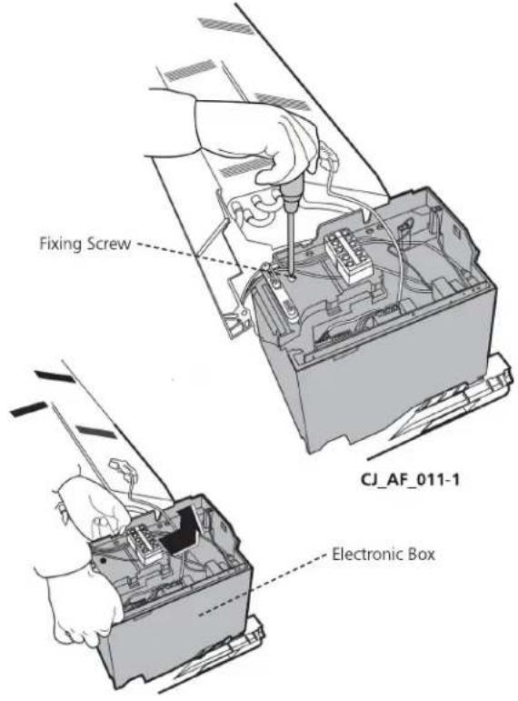 CJ_AF_011-2 CJ_AF_011-2 |
Note: This section is for reference only. Actual unit appearance may vary.
| Procedure | Illustration |
| 7) Remove the fixing screw, then remove the capacitor of fan motor (see CJ_AF_013). |  CJ_AF_013 CJ_AF_013 |
Note: This section is for reference only. Actual unit appearance may vary.
3. Evaporator
Note: Remove the front panel and electrical parts (refer to 1. Front panel and 2. Electrical parts) before disassembling evaporator.
| Procedure | Illustration |
| 1) Disassemble the pipe holder located at the rear of the unit (see CJ_AF_014). |  CJ_AF_014 CJ_AF_014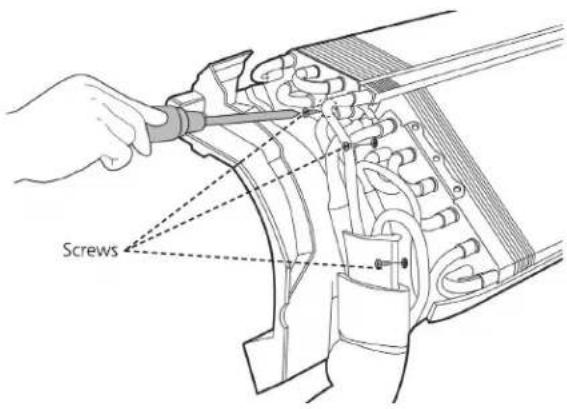 CJ_AF_015 CJ_AF_015 |
| 2) Remove the screws on the evaporator located at the fixed plate (see CJ_AF_015). | |
| 3) Remove the two screws on the evaporator located at the base of the bearing side (see CJ_AF_016). | 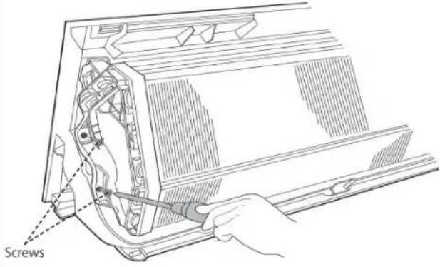 CJ_AF_016 CJ_AF_016 |
Note: This section is for reference only. Actual unit appearance may vary.
| Procedure | Illustration |
| 4) Pull out the evaporator (see CJ_AF_017). | 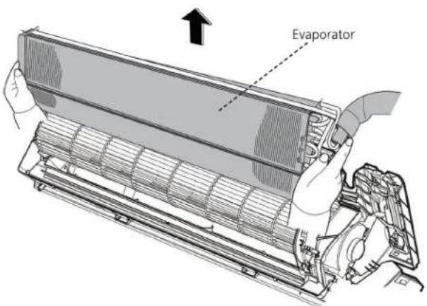 CJ_AF_017 CJ_AF_017 |
Note: This section is for reference only. Actual unit appearance may vary.
4. Fan motor and fan
Note: Remove the front panel, electrical parts and evaporator (refer to 1. Front panel, 2. Electrical parts, and 3. Evaporator). before disassembling fan motor and fan.
| Procedure | Illustration |
| 1) Remove the two screws and remove the fixing board of the fan motor (see CJ_AF_018). | 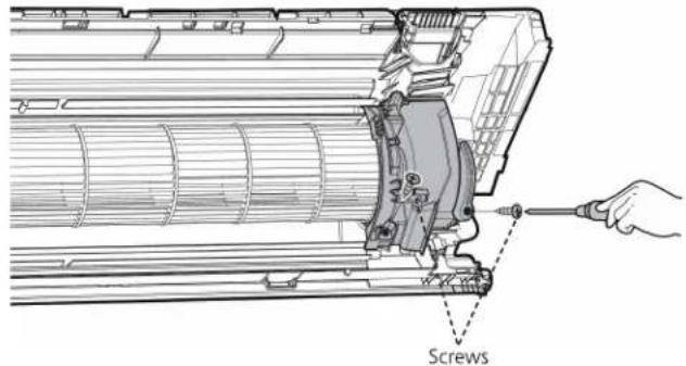 CJ_AF_018 CJ_AF_018 |
| 2) Remove the Bearing sleeve(see CJ_AF_019). |  CJ_AF_019 CJ_AF_019 |
| 3) Remove the fixing screw (see Fig CJ_AF_020). |  CJ_AF_020 CJ_AF_020 |
| 4) Pull out the fan motor and fan assembly from the side. |
Note: This section is for reference only. Actual unit appearance may vary.
5. Step motor
Note: Remove the front panel and electrical parts (refer to 1. Front panel, 2. Electrical parts) before disassembling step motor.
| Procedure | Illustration |
| 1) Remove the two screws, then remove the stepping motor (see CJ_AF_021). |  CJ_AF_021 CJ_AF_021 |
Note: This section is for reference only. Actual unit appearance may vary.
2.2 Outdoor unit
1. Panel Plate
PAC9337; PAC9137; PAC12337;
| Procedure | Illustration |
| 1) Turn off the air conditioner and the power breaker.2) Remove the screws of the big handle and then remove the big handle (2 screws) (see CJ_AA30_001). | 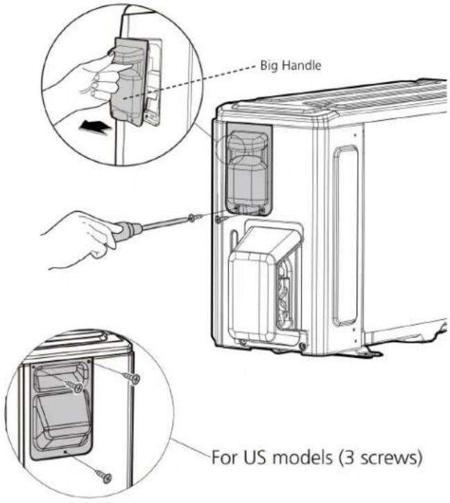 CJ_AA30_001 CJ_AA30_001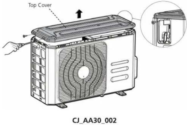 |
| 3) Remove the screws of the top cover and then remove the top cover (3 screws). One of the screws is located underneath the big handle (see CJ_AA30_002). |
Note: This section is for reference only. Actual unit appearance may vary.
| Procedure | Illustration |
| 4) Remove the screws of the front panel and then remove the front panel (6 screws) (see CJ_AA30_003). |  CJ_AA30_003 CJ_AA30_003 |
| 5) Remove the screws of water collecting cover (1 screw) (see CJ_AA30_004). |  CJ_AA30_004 CJ_AA30_004 |
Note: This section is for reference only. Actual unit appearance may vary.
| Procedure | Illustration |
| 6) Remove the screws of the right panel and then remove the right panel (6 screws) (see CJ_AA30_005). |  |
Note: This section is for reference only. Actual unit appearance may vary.
PAC12137;
| Procedure | Illustration |
| 1) Turn off the air conditioner and the power breaker.2) Remove the screws of the big handle and then remove the big handle (1 screws) (see CJ_AB30_001).3) Remove the screws of the top cover and then remove the top cover (3 screws). One of the screws is located underneath the big handle (see CJ_AB30_002). | 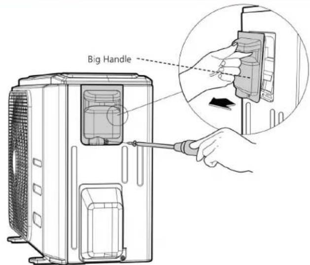  CJ_AB30_001 CJ_AB30_001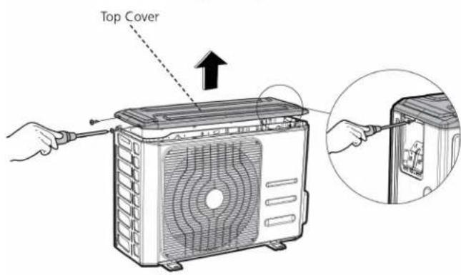 CJ_AB30_002 CJ_AB30_002 |
Note: This section is for reference only. Actual unit appearance may vary.
| Procedure | Illustration |
| 4) Remove the screws of the front panel and then remove the front panel (6 screws) (see CJ_AB30_003). |  |
| 5) Remove the screws of water collecting cover (1 screw) (see CJ_AB30_004). |  |
| CJ_AB30_004 |
Note: This section is for reference only. Actual unit appearance may vary.
| Procedure | Illustration |
| 6) Remove the screws of the right panel and then remove the right panel (5 screws) (see CJ_AB30_005). |  |
Note: This section is for reference only. Actual unit appearance may vary.
PAC18337
| Procedure | Illustration |
| 1) Turn off the air conditioner and the power breaker.2) Remove the screws of the big handle and then remove the big handle (1 screws) (see CJ_BA30_001). |  CJ_BA30_001 CJ_BA30_001 |
| 3) Remove the screws of the top cover and then remove the top cover (3 screws). One of the screws is located underneath the big handle (see CJ_BA30_002). |  |
Note: This section is for reference only. Actual unit appearance may vary.
| Procedure | Illustration |
| 4) Remove the screws of the front panel and then remove the front panel (7 screws) (see CJ_BA30_003). |  CJ_BA30_003 CJ_BA30_003 |
| 5) Remove the screws of water collecting cover (1 screw) (see CJ_BA30_004). |  CJ_BA30_004 CJ_BA30_004 |
Note: This section is for reference only. Actual unit appearance may vary.
| Procedure | Illustration |
| 6) Remove the screws of the rear net and then remove the rear net (2 screws)(see CJ_BA30_005). |  CJ_BA30_005 CJ_BA30_005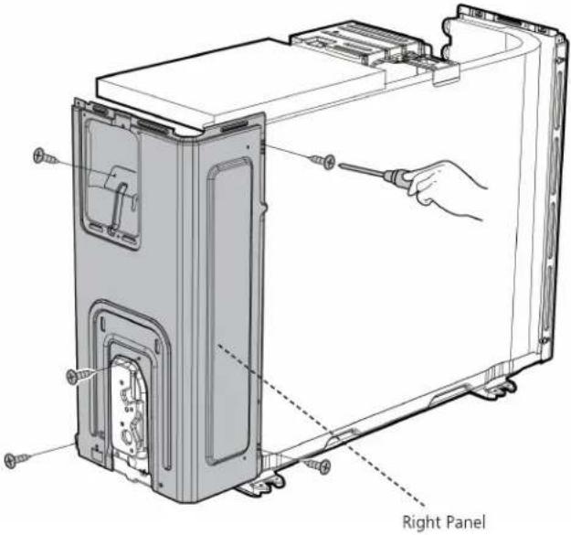 CJ_BA30_006 CJ_BA30_006 |
| 7) Remove the screws of the right paneland then remove the right panel(5 screws) (see CJ_BA30_006). |
Note: This section is for reference only. Actual unit appearance may vary.
PAC24337
| Procedure | Illustration |
| 1) Turn off the air conditioner and the power breaker.2) Remove the screws of the big handle and then remove the big handle (1 screws) (see CJ_CA30_001). |  CJ_CA30_001 CJ_CA30_001 |
| 3) Remove the screws of the top cover and then remove the top cover (3 screws). One of the screws is located underneath the big handle (see CJ_CA30_002). | 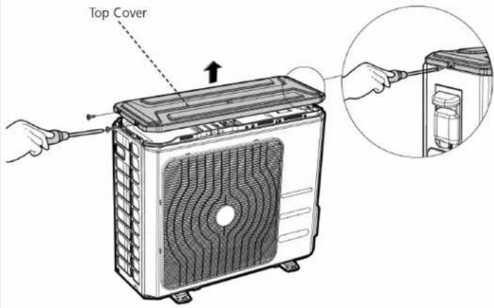 CJ_CA30_002 CJ_CA30_002 |
Note: This section is for reference only. Actual unit appearance may vary.
| Procedure | Illustration |
| 4) Remove the screws of the front panel and then remove the front panel (7 screws) (see CJ_CA30_003). | 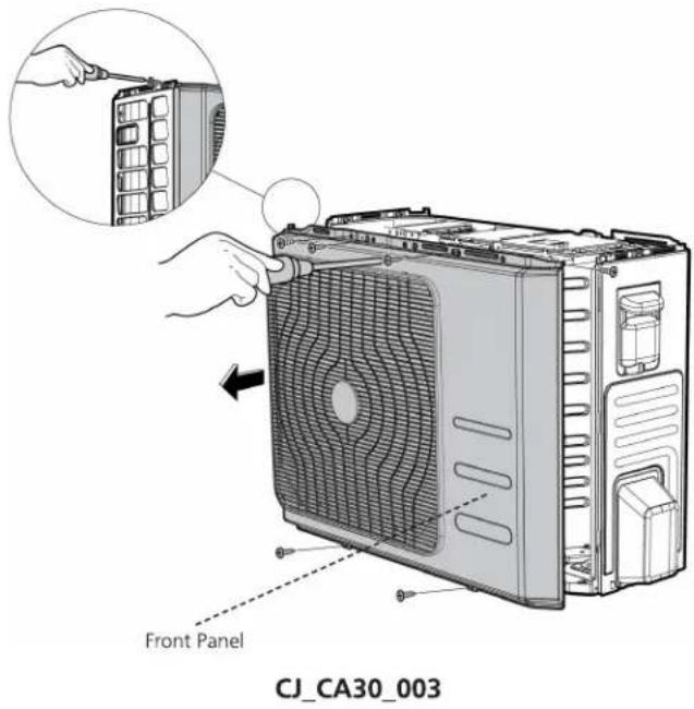 |
| 5) Remove the screws of water collecting cover and then remove the water collecting cover (1 screw) (see CJ_CA30_004). |  |
Note: This section is for reference only. Actual unit appearance may vary.
| Procedure | Illustration |
| 6) Remove the screws of the right panel and then remove the right panel (6 screws) (see CJ_CA30_005). | 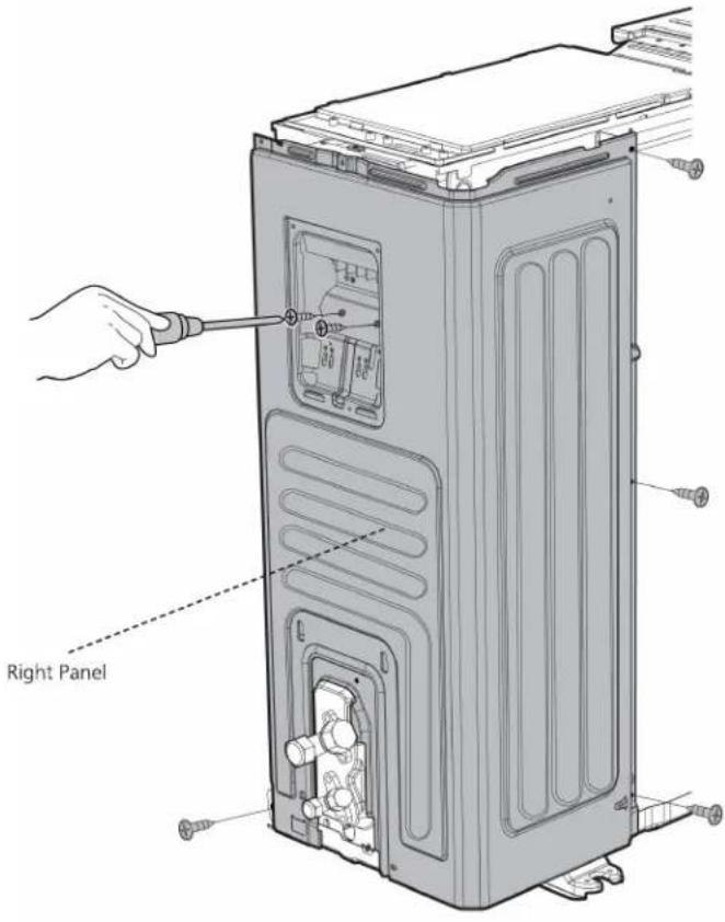 CJ_CA30_005 CJ_CA30_005 |
Note: This section is for reference only. Actual unit appearance may vary.
2. Fan disassembly
Note: Remove the panel plate and (refer to 1. Panel plate) before disassembling fan.
PAC9137; PAC12137; PAC9337; PAC12337; PAC18337
| Procedure | Illustration |
| 1) Remove the nut securing the fan with a spanner (see CJ_ODU_001).2) Remove the fan. |  |
| 3) Disconnect the connectors for fan motor. (Blue wire, yellow wire, red wire, brown wire and black wire. The blue wire and red wire are on the capacitor. The black wire connects with terminal 4.) (see CJ_ODU_002) |  |
Note: This section is for reference only. Actual unit appearance may vary.
| Procedure | Illustration |
| 4) Remove the fixing screws of the fan motor (4 screws) (see CJ_ODU_003).5) Remove the fan motor. |  CJ_ODU_003 CJ_ODU_003 |
Note: This section is for reference only. Actual unit appearance may vary.
PAC24337
| Procedure | Illustration |
| 1) Remove the nut securing the fan with a spanner (see CJ_ODU_004).2) Remove the fan. |  CJ_ODU_004 CJ_ODU_004 |
| 3) Disconnect the connectors for fan motor. (Blue wire, red wire, brown wire and black wire. The blue wire and brown wire are on the capacitor. The black wire connects with a terminal. And the red wire is on the borad.) (see CJ_ODU_005) |  CJ_ODU_005 CJ_ODU_005 |
Note: This section is for reference only. Actual unit appearance may vary.
| Procedure | Illustration |
| 4) Remove the fixing screws of the fan motor (4 screws) (see CJ_ODU_006).5) Remove the fan motor. | 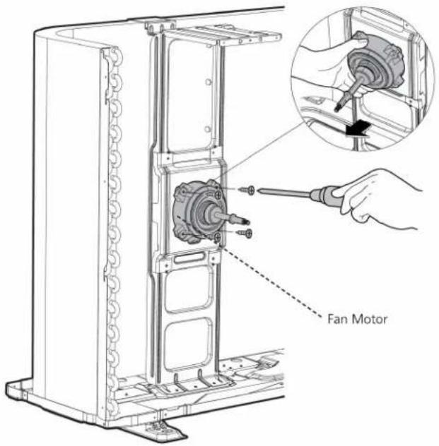 CJ_ODU_006 CJ_ODU_006 |
Note: This section is for reference only. Actual unit appearance may vary.
3. Electrical parts
Note: Remove the air outlet grille(refer to 1. Panel plate) before disassembling electrical parts.
PAC9137; PAC12137; PAC9337; PAC12337; PAC18337
| Procedure | Illustration |
| 1) Remove the two screws fixed the electronic control board (see CJ_ODU_007).2) Disconnect the wires connected to the compressor. (Black wire connects with terminal 1, blue wire and red wire connect with the compressor capacitor) (see CJ_ODU_007)3) Disconnect the wires connected to 4-way valve. (Blue wires on terminal 2&3) (see CJ_ODU_007)4) Remove the fixing screw of the compressor capacitor, then pull it out (see CJ_ODU_007)5) Remove the electrical parts (see CJ_ODU_007) |  CJ_ODU_007 CJ_ODU_007 |
Note: This section is for reference only. Actual unit appearance may vary.
PAC24337
| Procedure | Illustration |
| 1) Disconnect the wires connected to the compressor. (Red wire connects with PCB board, others connects with terminals) (see CJ_ODU_008)2) Disconnect the wires connected to 4-way valve. (see CJ_ODU_008)3) Disconnect the wires connected to the transformer. (see CJ_ODU_008)4) Disconnect the other wires connected to terminals. (see CJ_ODU_008)5) Remove the PCB board. (see CJ_ODU_008)6) Remove the screws of the capacitors. (see CJ_ODU_009) |   CJ_ODU_009 CJ_ODU_009 |
Note: This section is for reference only. Actual unit appearance may vary.
4. Sound blanket
WARNING: Recover refrigerant from the refrigerant circuit before remove the compressor.
Note: Remove the panel plate, electrical parts, and fan assembly (refer to 1. Panel plate, 2. Electrical parts, and 3. Fan assembly) before disassembling sound blanket.
| Procedure | Illustration |
| 1) Remove the sound blanket (side and top) (see CJ_ODU_010). |  |
Note: This section is for reference only. Actual unit appearance may vary.
5. Compressor
WARNING: Recover refrigerant from the refrigerant circuit before remove the compressor.
Note: Remove the panel plate, electrical parts, and fan assembly (refer to 1. Panel plate, 2. Electrical parts, and 3. Fan assembly) before disassembling compressor.
| Procedure | Illustration |
| 1) Remove the flange nut of terminal cover and remove the terminal cover (see CJ_ODU_011). | 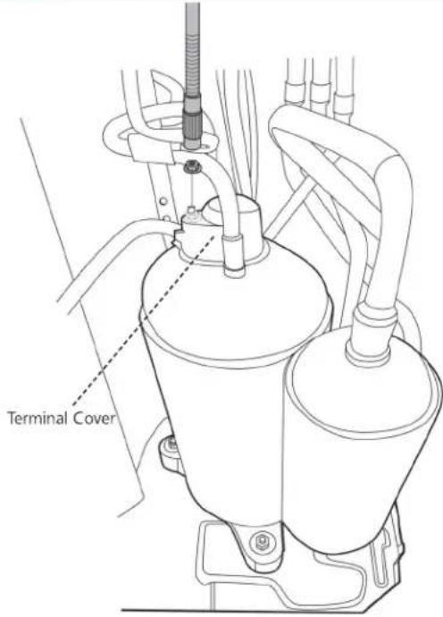 CJ_ODU_011 CJ_ODU_011 |
| 2) Disconnect the connectors (see CJ_ODU_012). |  CJ_ODU_012 CJ_ODU_012 |
Note: This section is for reference only. Actual unit appearance may vary.
| Procedure | Illustration |
| 3) Remove the hex nuts and washers securing the compressor, located on the bottom plate (see CJ_ODU_013). |  CJ_ODU_013 CJ_ODU_013 |
| 4) Heat up the brazed parts and then remove the discharge pipe and the suction pipe (see CJ_ODU_014).5) Lift the compressor from the base pan assembly with pliers. | 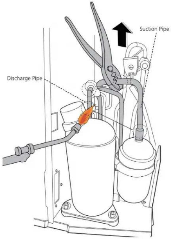 CJ_ODU_014 CJ_ODU_014 |
Note: This section is for reference only. Actual unit appearance may vary.
Troubleshooting
Contents
- Safety Caution ....55
- General Troubleshooting ....56
- Error Diagnosis and Troubleshooting Without Error Code....57
3.1 Remote maintenance....57
3.2 Field maintenance 58
- Quick Maintenance by Error Code....59
- Troubleshooting by Error Code....64
5.1 Common Check Procedures....64
5.2 EO(EEPROM parameter error)....65
5.3 E1(Indoor and outdoor unit communication error) (only for PAC24337).....66
5.4 E2 (Zero crossing detection error diagnosis and solution) 67
5.5 E3 (Fan speed has been out of control diagnosis and solution)....68
5.6 E4/E5 (Open circuit or short circuit of temperature sensor diagnosis and solution) 70
5.7 E7 (Indoor PCB /Display board communication error)....71
5.8 EC (Refrigerant Leakage Detection diagnosis and solution) 72
1. Safety Caution

WARNING
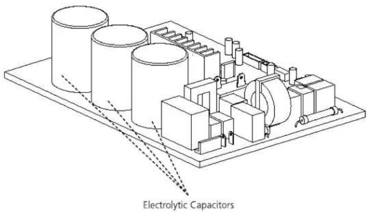
Electricity remains in capacitors even when the power supply is off. Ensure the capacitors are fully discharged before troubleshooting.
text_image
Electrolytic CapacitorsFor other models, connect discharge resistance (approx. 100 40W) or a soldering iron plug between the positive and negative terminals of the electrolytic capacitor. The terminals are located on the bottom surface of the outdoor PCB.

text_image
Discharging position (Discharging period 10 seconds or more) Plug of soldering ironNote: This picture is for reference only. Actual appearances may vary.
2. General Troubleshooting
2.1 Error Display (Indoor Unit)
When the indoor unit encounters a recognized error, the indicator light will flash in a corresponding series, the timer display may turn on or begin flashing, and an error code will be displayed. These error codes are described in the following table:
| Indicator flashes | Timer Display | Display | Error Information | Solution |
| 1 | OFF | E0 | Indoor unit EEPROM parameter error | Page 65 |
| 2 | OFF | E1 | Indoor / outdoor units communication error (only for PAC24337) | Page 66 |
| 3 | OFF | E2 | Zero-crossing signal detection error | Page 67 |
| 4 | OFF | E3 | The indoor fan speed is operating outside of the normal range | Page 68 |
| 5 | OFF | E4 | Indoor room temperature sensor T1 is in open circuit or has short circuited | Page 70 |
| 6 | OFF | E5 | Evaporator coil temperature sensor T2 is in open circuit or has short circuited | Page 70 |
| 9 | OFF | E7 | Indoor PCB /Display board communication error | Page 71 |
| 7 | OFF | EC | Refrigerant leak detected | Page 72 |
For other errors:
The display board may show a garbled code or a code undefined by the service manual. Ensure that this code is not a temperature reading.
Troubleshooting:
Test the unit using the remote control. If the unit does not respond to the remote, the indoor PCB requires replacement. If the unit responds, the display board requires replacement.
3. Error Diagnosis and Troubleshooting Without Error Code

WARNING
Be sure to turn off unit before any maintenance to prevent damage or injury.
3.1 Remote maintenance
SUGGESTION: When troubles occur, please check the following points with customers before field maintenance.
| Problem | Solution | |
| 1 | Unit will not start | Page 60-61 |
| 2 | The power switch is on but fans will not start | Page 60-61 |
| 3 | The temperature on the display board cannot be set | Page 60-61 |
| 4 | Unit is on but the wind is not cold(hot) | Page 60-61 |
| 5 | Unit runs, but shortly stops | Page 60-61 |
| 6 | The unit start ups and stops frequently | Page 60-61 |
| 7 | Unit runs continuously but insufficient cooling(heating) | Page 60-61 |
| 8 | Cool can not change to heat | Page 60-61 |
| 9 | Unit is noisy | Page 60-61 |
3.2 Field maintenance
| Problem | Solution | |
| 1 | Unit will not start | Page 62-63 |
| 2 | Compressor will not start but fans run | Page 62-63 |
| 3 | Compressor and condenser (outdoor) fan will not start | Page 62-63 |
| 4 | Evaporator (indoor) fan will not start | Page 62-63 |
| 5 | Condenser (Outdoor) fan will not start | Page 62-63 |
| 6 | Unit runs, but shortly stops | Page 62-63 |
| 7 | Compressor short-cycles due to overload | Page 62-63 |
| 8 | High discharge pressure | Page 62-63 |
| 9 | Low discharge pressure | Page 62-63 |
| 10 | High suction pressure | Page 62-63 |
| 11 | Low suction pressure | Page 62-63 |
| 12 | Unit runs continuously but insufficient cooling | Page 62-63 |
| 13 | Too cool | Page 62-63 |
| 14 | Compressor is noisy | Page 62-63 |
| 15 | Horizontal louver can not revolve | Page 62-63 |
4. Quick Maintenance by Error Code
If you do not have the time to test whether specific parts are faulty, you can directly change the required parts according to the error code.
You can find the parts to replace by error code in the following table.
| Part requiring replacement | Error Code | |||||||
| E0 | E1 | E2 | E3 | E4 | E5 | E7 | EC | |
| Indoor PCB | √ | √ | √ | √ | √ | √ | √ | √ |
| Outdoor PCB | x | √ | x | x | x | x | x | √ |
| Indoor fan motor | x | x | x | √ | x | x | x | x |
| Outdoor fan motor | x | x | x | x | x | x | x | x |
| Temperature sensor | x | x | x | x | √ | √ | x | x |
| T2 Sensor | x | x | x | x | x | x | x | √ |
| T3 Sensor | x | x | x | x | x | x | x | x |
| Additional refrigerant | x | x | x | x | x | x | x | √ |
| Display board | x | x | x | x | x | x | √ | x |
| Compressor | x | x | x | x | x | x | x | √ |
| Capacitor of compressor | x | x | x | x | x | x | x | √ |
| Capacitor of fan motor | x | x | x | x | x | x | x | √ |
Troubleshooting
| Test method / remedy | Unit is noisy | Cool can not change to heat | The unit starts up and stops frequently | Unit runs, but shortly stops | Unit is on but the wind is not cold(not) | The temperature on the display board cannot be set | The power switch is on but fans will not start | Unit will not start | Possible causes of trouble | 1. Remote Maintenance |
| Test voltage | ☆ | Power failure | Electrical Circuit | |||||||
| Close the power switch | ☆ | The main power tripped | ||||||||
| Inspect connections - tighten | ☆ | ☆ | Loose connections | |||||||
| Change the transformer | ☆ | ☆ | Faulty transformer | |||||||
| Test voltage | ☆ | ☆ | ☆ | The voltage is too high or too low | ||||||
| Replace the battery of the remote control | ☆ | The remote control is powered off | ||||||||
| Replace the remote control | ☆ | Broken remote control | ||||||||
| Clean or replace | ☆ | Dirty air filter | Refrigerant Circuit | |||||||
| Clean | ☆ | Dirty condenser fins | ||||||||
| Adjust the setting temperature | ☆ | ☆ | ☆ | The setting temperature is higher/lower than the room's(cooling/heating) | ||||||
| Turn the AC later | ☆ | ☆ | ☆ | ☆ | The ambient temperature is too high/low when the mode is cooling/heating | |||||
| Adjust to cool mode | ☆ | Fan mode | ||||||||
| Turn off SILENCE function. | ☆ | SILENCE function is activated(optional function) | ||||||||
| Turn the AC later | ☆ | Frosting and defrosting frequently |
| Check heat load | ☆ | Heavy load condition | Others | ||||||||
| Tighten bolts or screws | ☆ | Loosen hold down bolts and / or screws | |||||||||
| Close all the windows and doors | ☆ | Bad airproof | |||||||||
| Remove the obstacles | ☆ | ☆ | The air inlet or outlet of either unit is blocked | ||||||||
| Reconnect the power or press ON/OFF button on remote control to restart | ☆ | Interference from cell phone towers and remote boosters | |||||||||
| Remove them | ☆ | Shipping plates remain attached |
Troubleshooting
| Test method / remedy | Horizontal louver can not revolve | Compressor is noisy | Too cool | Unit runs continuously but insufficient cooling | Low suction pressure | High suction pressure | Low discharge pressure | High discharge pressure | Compressor short-cycles due to overload | Unit runs, but shortly stops | Condenser (Outdoor) fan will not start | Evaporator (indoor) fan will not start | Compressor and condenser (outdoor) fan will not start | Compressor will not start but fans run | Unit will not start | Possible causes of trouble | 2.Field Maintenance |
| Test voltage | ☆ | Power failure | Electrical Circuit | ||||||||||||||
| Inspect fuse type & size | ☆ | Blown fuse or varistor | |||||||||||||||
| Inspect connections - tighten | ☆ | ☆ | Loose connections | ||||||||||||||
| Test circuits with tester | ☆ | ☆ | ☆ | ☆ | ☆ | Shorted or broken wires | |||||||||||
| Test continuity of safety device | ☆ | Safety device opens | |||||||||||||||
| Test continuity of thermostat / sensor & wiring | ☆ | ☆ | ☆ | ☆ | Faulty thermostat / room temperature sensor | ||||||||||||
| Place the temperature sensor at the central of the air inlet grille | ☆ | Wrong setting place of temperature sensor | |||||||||||||||
| Check control circuit with tester | ☆ | Faulty transformer | |||||||||||||||
| Check capacitor with tester | ☆ | ☆ | ☆ | Shorted or open capacitor | |||||||||||||
| Test continuity of coil & contacts | ☆ | ☆ | ☆ | ☆ | Faulty magnetic contactor for compressor | ||||||||||||
| Test continuity of coil & contacts | ☆ | ☆ | Faulty magnetic contactor for fan | ||||||||||||||
| Test voltage | ☆ | ☆ | Low voltage | ||||||||||||||
| Replace the stepping motor | ☆ | Faulty stepping motor | |||||||||||||||
| Check resistance with multimeter | ☆ | Shorted or grounded compressor | |||||||||||||||
| Check resistance with multimeter | ☆ | ☆ | Shorted or grounded fan motor |
| Replace the compressor | ☆ | Compressor stuck | Refrigerant Circuit | |||||||||||||
| Leak test | ☆ | ☆ | ☆ | ☆ | ☆ | Shortage of refrigerant | ||||||||||
| Replace restricted part | ☆ | ☆ | ☆ | Restricted liquid line | ||||||||||||
| Clean or replace | ☆ | ☆ | Dirty air filter | |||||||||||||
| Clean coil | ☆ | ☆ | Dirty evaporator coil | |||||||||||||
| Check fan | ☆ | ☆ | Insufficient air through evaporator coil | |||||||||||||
| Change charged refrigerant volume | ☆ | ☆ | ☆ | ☆ | ☆ | Overcharge of refrigerant | ||||||||||
| Clean condenser or remove obstacle | ☆ | ☆ | ☆ | ☆ | Dirty or partially blocked condenser | |||||||||||
| Purge, evacuate and recharge | ☆ | ☆ | Air or incompressible gas in refrigerant cycle | |||||||||||||
| Remove obstruction to air flow | ☆ | ☆ | Short cycling of condensing air | |||||||||||||
| Remove obstruction in air or water flow | ☆ | High temperature condensing medium | ||||||||||||||
| Remove obstruction in air or water flow | ☆ | Insufficient condensing medium | ||||||||||||||
| Replace compressor | ☆ | Broken compressor internal parts | ||||||||||||||
| Test compressor efficiency | ☆ | ☆ | ☆ | Inefficient compressor | ||||||||||||
| Replace valve | ☆ | Expansion valve obstructed | ||||||||||||||
| Replace valve | ☆ | ☆ | Expansion valve or capillary tube closed completely | |||||||||||||
| Replace valve | ☆ | ☆ | Leaking power element on expansion valve | |||||||||||||
| Fix feeler bulb | ☆ | Poor installation of feeler bulb | ||||||||||||||
| Check heat load | ☆ | ☆ | Heavy load condition | Others | ||||||||||||
| Tighten bolts or screws | ☆ | Loosen hold down bolts and / or screws | ||||||||||||||
| Remove them | ☆ | Shipping plates remain attached | ||||||||||||||
| Choose AC of lager capacity or add the number of AC | ☆ | Poor choices of capacity | ||||||||||||||
| Rectify piping so as not to contact each other or with external plate | ☆ | Contact of piping with other piping or external plate |
5. Troubleshooting by Error Code
5.1 Common Check Procedures
5.1.1 Temperature Sensor Check
Disconnect the temperature sensor from PCB, measure the resistance value with a tester.
Temperature Sensors.
Room temp.(T1) sensor,
Indoor coil temp.(T2) sensor,
Outdoor coil temp.(T3) sensor,
Outdoor ambient temp.(T4) sensor,
Measure the resistance value of each winding by using the multi-meter.
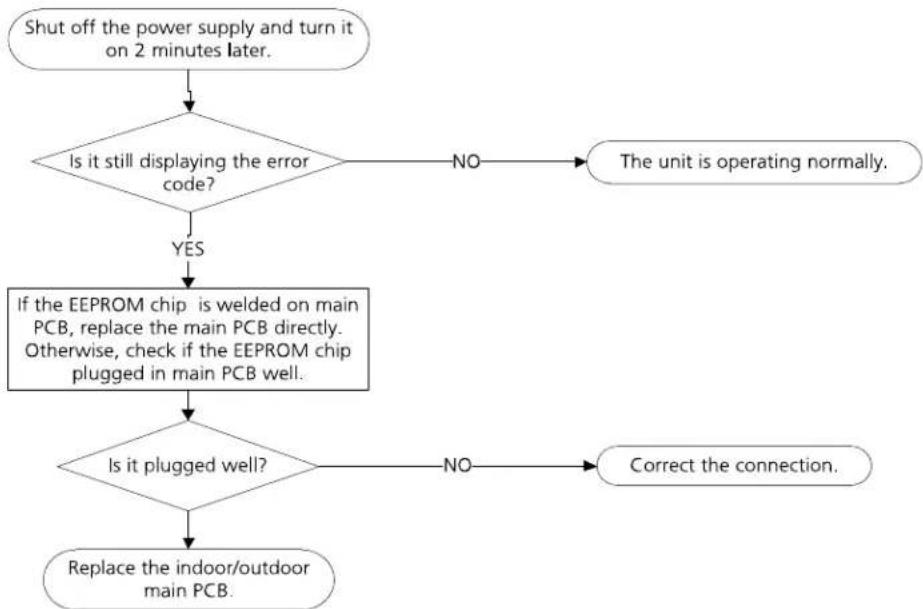
5.2 E0 (EEPROM parameter error)
Description: Indoor or outdoor PCB main chip does not receive feedback from EEPROM chip.
Recommended parts to prepare:
- Indoor PCB
- Outdoor PCB
Troubleshooting and repair:
flowchart
graph TD
    A["Shut off the power supply and turn it on 2 minutes later."] --> B{Is it still displaying the error code?}
    B -->|NO| C["The unit is operating normally."]
    B -->|YES| D["If the EEPROM chip is welded on main PCB, replace the main PCB directly. Otherwise, check if the EEPROM chip plugged in main PCB well."]
    D --> E{Is it plugged well?}
    E -->|NO| F["Correct the connection."]
    E -->|YES| G["Replace the indoor/outdoor main PCB."]
Remarks:
The location of the EEPROM chip on the indoor and outdoor PCB is shown in the following two images:

text_image
EEPROM Chip XXXXE23 EEPROM ChipNote: These images are for reference only.
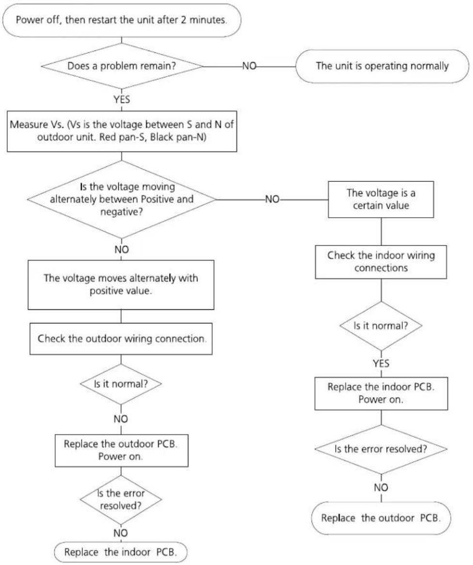
5.3 E1 (Indoor and outdoor unit communication error) (only for PAC24337)
Description: The indoor unit has not received feedback from the outdoor unit for 110 seconds, four consecutive times.
Recommended parts to prepare:
- Indoor PCB
- Outdoor PCB
- Reactor
Troubleshooting and repair:
flowchart
graph TD
    A["Power off, then restart the unit after 2 minutes."] --> B{Does a problem remain?}
    B -->|YES| C["Measure Vs. (Vs is the voltage between S and N of outdoor unit. Red pan-S, Black pan-N)"]
    B -->|NO| D["The unit is operating normally"]
    C --> E{Is the voltage moving alternately between Positive and negative?}
    E -->|NO| F["The voltage moves alternately with positive value"]
    E -->|NO| G["The voltage is a certain value"]
    F --> H["Check the outdoor wiring connection"]
    H --> I{Is it normal?}
    I -->|NO| J["Replace the outdoor PCB. Power on."]
    I -->|YES| K["Replace the indoor PCB. Power on."]
    J --> L{Is the error resolved?}
    L -->|NO| M["Replace the indoor PCB."]
    L -->|YES| N{Is the error resolved?}
    N -->|NO| O["Replace the outdoor PCB."]
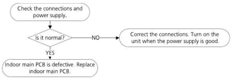
5.4 E2 (Zero crossing detection error diagnosis and solution)
Description: When PCB does not receive zero crossing signal feedback for 4 minutes or the zero crossing signal time interval is abnormal.
Recommended parts to prepare:
- Connection mistake
- PCB faulty
Troubleshooting and repair:
flowchart
graph TD
    A["Check the connections and power supply."] --> B{Is it normal?}
    B -->|NO| C["Correct the connections. Turn on the unit when the power supply is good."]
    B -->|YES| D["Indoor main PCB is defective. Replace indoor main PCB."]
5.5 E3(Fan speed has been out of control diagnosis and solution)
Description: When indoor fan speed keeps too low (300RPM) for certain time, the unit will stop and the LED will display the failure.
Recommended parts to prepare:
- Wiring mistake
• Faulty fan assembly'y faulty - Faulty fan motor
- Faulty PCB
Troubleshooting and repair:

flowchart
graph TD
    A["Power off, then restart the unit after 2 minutes."] --> B{Does a problem remain?}
    B -->|NO| C["The unit is operating normally"]
    B -->|YES| D["Shut off the power supply, Rotate the fan by hand."]
    D --> E{Does it turn easily?}
    E -->|NO| F["Find the cause of the problem and resolve it"]
    E -->|YES| G["Check the wiring of fan motor."]
    G --> H{Is it improperly wired?}
    H -->|YES| I["Measure the voltage for the fan motor from the PCB."]
    H -->|NO| J["Ensure proper connections"]
    I --> K{Is it within normal parameters?}
    K -->|YES| L["Replace the fan motor"]
    K -->|NO| M["Replace the indoor PCB"]
    L --> N["End"]
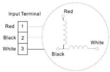
Index:
1. Indoor AC Fan Motor
Power on and set the unit running in fan mode at high fan speed. After running for 15 seconds, measure the voltage of pin1 and pin2. If the value of the voltage is less than 100V(208\~240V power supply) or 50V(115V power supply), the PCB must has problems and need to be replaced.
text_image
Input Terminal Red 1 Black 2 White 3 Red Black White5.6 E4/E5 (Open circuit or short circuit of temperature sensor diagnosis and solution)
Description: If the sampling voltage is lower than 0.06V or higher than 4.94V, the LED will display the failure.
Recommended parts to prepare:
- Wiring mistake
- Faulty sensor
- Faulty PCB
Troubleshooting and repair:

flowchart
graph TD
    A["Check the connection between temperature sensor and PCB."] --> B{Is it properly wired?}
    B -->|NO| C["Ensure proper connections."]
    B -->|YES| D["Measure the resistance value of the sensor."]
    D --> E{Is it within acceptable parameters?}
    E -->|NO| F["Replace the Sensor."]
    E -->|YES| G["Replace indoor or outdoor PCB"]

text_image
FLLKE 178 DIGITAL MULTIMETER 09,10 Amm Range HOLD RANGE REL Hz %5.7 E7 (Indoor PCB /Display board communication error)
Description: Indoor PCB does not receive feedback from Display board.
Recommended parts to prepare:
- Wiring mistake
- Faulty PCB
• Display board malfunction
Troubleshooting and repair:

flowchart
graph TD
    A["Power off, then restart the unit 2 minutes later."] --> B{Is it still displaying the error code?}
    B -->|NO| C["The unit is operating normally."]
    B -->|YES| D["Check the wirings and connection."]
    D --> E{Are all the connections good?}
    E -->|NO| F["Correct the connection or replace the Wirings."]
    E -->|YES| G["Replace the indoor main PCB."]
    G --> H{Is the error extinguished?}
    H -->|NO| I["Replace the Display board."]
5.8 EC (Refrigerant Leakage Detection diagnosis and solution)
Description: Define the evaporator coil temp.T2 of the compressor just starts running as Tcool.
In the beginning 5 minutes after the compressor starts up, if T2<Tcool-2°C does not keep continuous 4 seconds and this situation happens 3 times, the display area will show "EC" and AC will turn off.
Recommended parts to prepare:
- Faulty T2 sensor
- Faulty compressor
• Faulty capacitor of compressor - Faulty indoor PCB
• System problems, such as leakage or blockages
• Faulty capacitor of fan motor - Faulty outdoor fan
Troubleshooting and repair:

flowchart
graph TD
    A["Power off, then restart the unit 2 minutes later."] --> B{Does a problem remain?}
    B -->|YES| C["Put your hands in front of the indoor air outlet."]
    C --> D{Is there cool air blowing out from indoor air outlet?}
    D -->|YES| E["Check the T2 sensor."]
    D -->|NO| F["The compressor does not operate"]
    D -->|NO| G["The compressor operates several minutes then ceases"]
    D -->|NO| H["The compressor is operating constantly"]
    F --> I["Replace the capacitor of compressor"]
    G --> J["Replace the capacitor of fan motor"]
    H --> K["Check system for leakages."]
    I --> L{Does a problem remain?}
    J --> M{Does a problem remain?}
    K --> N{Are any leakages present?}
    L --> O["Replace the compressor"]
    M --> P["Replace the outdoor fan"]
    N --> Q["Check System for blockages and clear blockages if present."]
    O --> R["Reinsert the T2 sensor"]
    P --> S["Repair the leakage and recharge the refrigerant."]
    Q --> T["Reinsert the T2 sensor"]
    S --> U{Is it within acceptable parameters?}
    T --> V{Is it securely attached?}
    U -->|NO| V
    V -->|YES| W["Measure the resistance value of the sensor."]
    W --> X{Is it within acceptable parameters?}
    X -->|NO| Y["Replace the sensor."]
    X -->|YES| Z["Replace indoor PCB"]
    Y --> AA["Repair the leakage and recharge the refrigerant."]
Appendix
Contents
i) Temperature Sensor Resistance Value Table for T1, T2, T3, and T4 (°C – K) ....74
ii) Pressure On Service Port 75
i) Temperature Sensor Resistance Value Table for T1,T2,T3 and T4 (°C - K)
| °C | °F | K Ohm | °C | °F | K Ohm | °C | °F | K Ohm | °C | °F | K Ohm |
| -20 | -4 | 115.266 | 20 | 68 | 12.6431 | 60 | 140 | 2.35774 | 100 | 212 | 0.62973 |
| -19 | -2 | 108.146 | 21 | 70 | 12.0561 | 61 | 142 | 2.27249 | 101 | 214 | 0.61148 |
| -18 | 0 | 101.517 | 22 | 72 | 11.5 | 62 | 144 | 2.19073 | 102 | 216 | 0.59386 |
| -17 | 1 | 96.3423 | 23 | 73 | 10.9731 | 63 | 145 | 2.11241 | 103 | 217 | 0.57683 |
| -16 | 3 | 89.5865 | 24 | 75 | 10.4736 | 64 | 147 | 2.03732 | 104 | 219 | 0.56038 |
| -15 | 5 | 84.219 | 25 | 77 | 10 | 65 | 149 | 1.96532 | 105 | 221 | 0.54448 |
| -14 | 7 | 79.311 | 26 | 79 | 9.55074 | 66 | 151 | 1.89627 | 106 | 223 | 0.52912 |
| -13 | 9 | 74.536 | 27 | 81 | 9.12445 | 67 | 153 | 1.83003 | 107 | 225 | 0.51426 |
| -12 | 10 | 70.1698 | 28 | 82 | 8.71983 | 68 | 154 | 1.76647 | 108 | 226 | 0.49989 |
| -11 | 12 | 66.0898 | 29 | 84 | 8.33566 | 69 | 156 | 1.70547 | 109 | 228 | 0.486 |
| -10 | 14 | 62.2756 | 30 | 86 | 7.97078 | 70 | 158 | 1.64691 | 110 | 230 | 0.47256 |
| -9 | 16 | 58.7079 | 31 | 88 | 7.62411 | 71 | 160 | 1.59068 | 111 | 232 | 0.45957 |
| -8 | 18 | 56.3694 | 32 | 90 | 7.29464 | 72 | 162 | 1.53668 | 112 | 234 | 0.44699 |
| -7 | 19 | 52.2438 | 33 | 91 | 6.98142 | 73 | 163 | 1.48481 | 113 | 235 | 0.43482 |
| -6 | 21 | 49.3161 | 34 | 93 | 6.68355 | 74 | 165 | 1.43498 | 114 | 237 | 0.42304 |
| -5 | 23 | 46.5725 | 35 | 95 | 6.40021 | 75 | 167 | 1.38703 | 115 | 239 | 0.41164 |
| -4 | 25 | 44 | 36 | 97 | 6.13059 | 76 | 169 | 1.34105 | 116 | 241 | 0.4006 |
| -3 | 27 | 41.5878 | 37 | 99 | 5.87359 | 77 | 171 | 1.29078 | 117 | 243 | 0.38991 |
| -2 | 28 | 39.8239 | 38 | 100 | 5.62961 | 78 | 172 | 1.25423 | 118 | 244 | 0.37956 |
| -1 | 30 | 37.1988 | 39 | 102 | 5.39689 | 79 | 174 | 1.2133 | 119 | 246 | 0.36954 |
| 0 | 32 | 35.2024 | 40 | 104 | 5.17519 | 80 | 176 | 1.17393 | 120 | 248 | 0.35982 |
| 1 | 34 | 33.3269 | 41 | 106 | 4.96392 | 81 | 178 | 1.13604 | 121 | 250 | 0.35042 |
| 2 | 36 | 31.5635 | 42 | 108 | 4.76253 | 82 | 180 | 1.09958 | 122 | 252 | 0.3413 |
| 3 | 37 | 29.9058 | 43 | 109 | 4.5705 | 83 | 181 | 1.06448 | 123 | 253 | 0.33246 |
| 4 | 39 | 28.3459 | 44 | 111 | 4.38736 | 84 | 183 | 1.03069 | 124 | 255 | 0.3239 |
| 5 | 41 | 26.8778 | 45 | 113 | 4.21263 | 85 | 185 | 0.99815 | 125 | 257 | 0.31559 |
| 6 | 43 | 25.4954 | 46 | 115 | 4.04589 | 86 | 187 | 0.96681 | 126 | 259 | 0.30754 |
| 7 | 45 | 24.1932 | 47 | 117 | 3.88673 | 87 | 189 | 0.93662 | 127 | 261 | 0.29974 |
| 8 | 46 | 22.5662 | 48 | 118 | 3.73476 | 88 | 190 | 0.90753 | 128 | 262 | 0.29216 |
| 9 | 48 | 21.8094 | 49 | 120 | 3.58962 | 89 | 192 | 0.8795 | 129 | 264 | 0.28482 |
| 10 | 50 | 20.7184 | 50 | 122 | 3.45097 | 90 | 194 | 0.85248 | 130 | 266 | 0.2777 |
| 11 | 52 | 19.6891 | 51 | 124 | 3.31847 | 91 | 196 | 0.82643 | 131 | 268 | 0.27078 |
| 12 | 54 | 18.7177 | 52 | 126 | 3.19183 | 92 | 198 | 0.80132 | 132 | 270 | 0.26408 |
| 13 | 55 | 17.8005 | 53 | 127 | 3.07075 | 93 | 199 | 0.77709 | 133 | 271 | 0.25757 |
| 14 | 57 | 16.9341 | 54 | 129 | 2.95896 | 94 | 201 | 0.75373 | 134 | 273 | 0.25125 |
| 15 | 59 | 16.1156 | 55 | 131 | 2.84421 | 95 | 203 | 0.73119 | 135 | 275 | 0.24512 |
| 16 | 61 | 15.3418 | 56 | 133 | 2.73823 | 96 | 205 | 0.70944 | 136 | 277 | 0.23916 |
| 17 | 63 | 14.6181 | 57 | 135 | 2.63682 | 97 | 207 | 0.68844 | 137 | 279 | 0.23338 |
| 18 | 64 | 13.918 | 58 | 136 | 2.53973 | 98 | 208 | 0.66818 | 138 | 280 | 0.22776 |
| 19 | 66 | 13.2631 | 59 | 138 | 2.44677 | 99 | 210 | 0.64862 | 139 | 282 | 0.22231 |
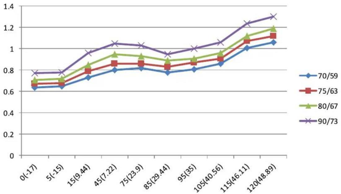
ii) Pressure On Service Port(R410A)
Cooling chart:
| °F(°C) | ODT IDT | 0(-17) | 5(-15) | 15 (9.44) | 45 (7.22) | 75 (23.89) | 85 (29.44) | 95 (35) | 105 (40.56) | 115 (46.11) | 120 (48.89) |
| BAR | 70/59 | 6.4 | 6.5 | 7.3 | 8.0 | 8.2 | 7.8 | 8.1 | 8.6 | 10.1 | 10.6 |
| BAR | 75/63 | 6.7 | 6.8 | 7.9 | 8.6 | 8.6 | 8.3 | 8.7 | 9.1 | 10.7 | 11.2 |
| BAR | 80/67 | 7.1 | 7.2 | 8.5 | 9.5 | 9.3 | 8.9 | 9.1 | 9.6 | 11.2 | 11.9 |
| BAR | 90/73 | 7.7 | 7.8 | 9.6 | 10.5 | 10.3 | 9.5 | 10.0 | 10.6 | 12.4 | 13.0 |
| °F(°C) | ODT IDT | 0(-17) | 5(-15) | 15 (9.44) | 45 (7.22) | 75 (23.89) | 85 (29.44) | 95 (35) | 105 (40.56) | 115 (46.11) | 120 (48.89) |
| PSI | 70/59 | 93 | 94 | 106 | 116 | 119 | 113 | 117 | 125 | 147 | 154 |
| PSI | 75/63 | 97 | 99 | 115 | 125 | 124 | 120 | 126 | 132 | 155 | 162 |
| PSI | 80/67 | 103 | 104 | 123 | 138 | 135 | 129 | 132 | 140 | 162 | 173 |
| PSI | 90/73 | 112 | 113 | 139 | 152 | 149 | 138 | 145 | 154 | 180 | 189 |
| °F(°C) | ODT IDT | 0(-17) | 5(-15) | 15 (9.44) | 45 (7.22) | 75 (23.89) | 85 (29.44) | 95 (35) | 105 (40.56) | 115 (46.11) | 120 (48.89) |
| MPA | 70/59 | 0.64 | 0.65 | 0.73 | 0.8 | 0.82 | 0.78 | 0.81 | 0.86 | 1.01 | 1.06 |
| MPA | 75/63 | 0.67 | 0.68 | 0.79 | 0.86 | 0.86 | 0.83 | 0.87 | 0.91 | 1.07 | 1.12 |
| MPA | 80/67 | 0.71 | 0.72 | 0.85 | 0.95 | 0.93 | 0.89 | 0.91 | 0.96 | 1.12 | 1.19 |
| MPA | 90/73 | 0.77 | 0.78 | 0.96 | 1.05 | 1.03 | 0.95 | 1 | 1.06 | 1.24 | 1.3 |