VS-21DTP - Prekidač Kramer - Besplatni korisnički priručnik
Pronađite besplatno priručnik za uređaj VS-21DTP Kramer u PDF formatu.

Pitanja korisnika o VS-21DTP Kramer
0 pitanje o ovom uređaju. Odgovorite na one koje znate ili postavite svoje.
Postavi novo pitanje o ovom uređaju
Preuzmite upute za vaš Prekidač u PDF formatu besplatno! Pronađite svoj priručnik VS-21DTP - Kramer i uzmite svoju elektroničku napravu natrag u ruke. Na ovoj stranici objavljeni su svi dokumenti potrebni za korištenje vaše naprave. VS-21DTP marke Kramer.
KORISNIČKI PRIRUČNIK VS-21DTP Kramer

Scan for full manual
VS-21DTP Quick Start Guide
This guide helps you install and use your VS-21DTP for the first time.
Go to www.kramerav.com/downloads/VS-21DTP to download the latest user manual and check if firmware upgrades are available.
Step 1: Check what's in the box
VS-21DTP 2xHDMI to HDBT Standby Switcher/POE
1 Power adapter and cord

1 Bracket set

1 Quick start guide

4 Rubber feet
Step 2: Get to know your VS-21DTP
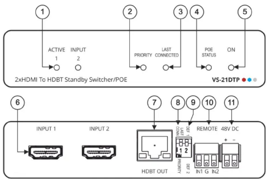
| # | Feature | Function |
| 1 | ACTIVE INPUT LEDs (1 to 2) | Lights green when the input is active. Both LEDs flash when no input is active. |
| 2 | PRIORITY LED | Lights green when DIP-switch 1 is set to PRIORITY (down). |
| 3 | LAST CONNECTED LED | Lights green when DIP-switch 1 is set to LAST CONNECTED (up). |
| 4 | POE STATUS LED | Lights green when the unit provides PoE. |
| 5 | ON LED | Lights green when the unit is powered on via power adapter or PoE. |
| 6 | INPUT HDMITM Connectors (1 to 2) | Connect to an HDMI source. |
| 7 | HDBT OUT RJ-45 Connector | Connect to an HDBaseT receiver (for example, TP-580R) and provide or accept power (bidirectional PoE). |
| 8 | LAST CONN/PRIORITY DIP-switch 1 | Set DIP-switch 1 up (off) to select the Last Connected input.Set DIP-switch 1 down (on) to select the Priority input determined by DIP-switch 2. |
| 9 | DEF 1/DEF 2 DIP-switch 2 | Set DIP-switch 2 up (off) to define INPUT 1 as the default (priority) input.Set DIP-switch 2 down (on) to define INPUT 2 as the default (priority) input. |
| 10 | REMOTE 3-pin Terminal Block Connector | Connects to optional contact closure switches 1 or 2 for manual switching (by momentary contact between the desired pin and the G pin). |
| 11 | 48V DC Power Terminal Block Connector | Connect to the Kramer power adapter. |
The terms HDMI, HDMI High-Definition Multimedia Interface, and the HDMI Logo are trademarks or registered trademarks of HDMI Licensing Administrator, Inc.
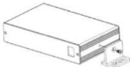
Step 3: Mount VS-21DTP
Install VS-21DTP using one of the following methods:
- Attach the rubber feet and place the unit on a flat surface.
- Fasten a bracket (included) on each side of the unit and attach it to a flat surface (see www.kramerav.com/downloads/VS-21DTP).
- Mount the unit in a rack using the recommended rack adapter (see www.kramerav.com/product/VS-21DTP).

- Ensure that the environment (e.g., maximum ambient temperature & air flow) is compatible for the device.
- Avoid uneven mechanical loading.
- Appropriate consideration of equipment nameplate ratings should be used for avoiding overloading of the circuits.
- Reliable earthing of rack-mounted equipment should be maintained.
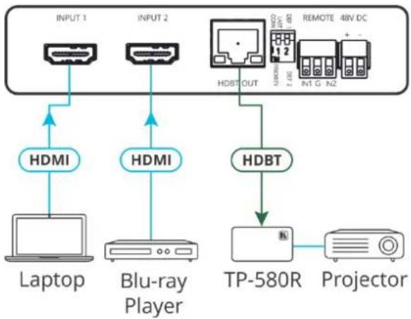
Step 4: Connect inputs and outputs
Always switch OFF the power on each device before connecting it to your VS-21DTP.
flowchart
graph TD
    A["INPUT 1"] --> B["HDMI"]
    C["INPUT 2"] --> D["HDMI"]
    E["Laptop"] --> F["Blu-ray Player"]
    G["PT-580R"] --> H["Projector"]
    I["HDBT OUT"] --> J["Remote 48V DC"]
    K["HDBT"] --> L["TP-580R"]
    M["HDMI"] --> N["Blu-ray Player"]
DIP-switches Setup:
A switch that is down is on; a switch that is up is off. By default, both switches are up (off).
Video Switching Selection:
| DIP-switch 1 | DIP-switch 2 | Video Input Selection |
| PRIORITY (down) | DEF 1 (up) | INPUT 1 is the default priority setup and is automatically switched to the output. |
| DEF 2 (down) | INPUT 2 is the default priority setup and is automatically switched to the output. | |
| LAST CONNECTED (up) | N/A | The last connected source is switched to the output (a reactivated or reconnected source becomes the new “Last Connected” source). |
Contact Closure Switches (Manual Override):
Controlling via the remote contact closure pushbuttons overrides all DIP-switch settings and automatic switching until the manually selected source disconnects, becomes inactive or the VS-21DTP is powered off.
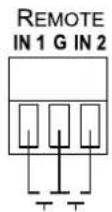
| Select INPUT 1 | Momentarily connect REMOTE IN 1 to PIN G (ground). |
| Select INPUT 2 | Momentarily connect REMOTE IN 2 to PIN G (ground). |

To achieve specified extension distances, use the recommended Kramer cables available at www.kramerav.com/product/VS-21DTP.
Using third-party cables may cause damage!
Step 5: Connect power
Connect the power cord to VS-21DTP and plug it into the mains electricity.

Safety Instructions (See www.kramerav.com for updated safety information)
Caution:
- For products with relay terminals and GPI/O ports, please refer to the permitted rating for an external connection, located next to the terminal or in the User Manual.
- There are no operator serviceable parts inside the unit.
Warning:
- Use only the power cord that is supplied with the unit.
- Disconnect the power and unplug the unit from the wall before installing.
- Do not open the unit. High voltages can cause electrical shock! Servicing by qualified personnel only.
• To ensure continuous risk protection, replace fuses only according to the rating specified on the product label which located on the bottom of the unit.