ASP510 - Audio snimač Audient - Besplatni korisnički priručnik
Pronađite besplatno priručnik za uređaj ASP510 Audient u PDF formatu.

Pitanja korisnika o ASP510 Audient
0 pitanje o ovom uređaju. Odgovorite na one koje znate ili postavite svoje.
Postavi novo pitanje o ovom uređaju
Preuzmite upute za vaš Audio snimač u PDF formatu besplatno! Pronađite svoj priručnik ASP510 - Audient i uzmite svoju elektroničku napravu natrag u ruke. Na ovoj stranici objavljeni su svi dokumenti potrebni za korištenje vaše naprave. ASP510 marke Audient.
KORISNIČKI PRIRUČNIK ASP510 Audient
operation
manual
audient
SURROUND SOUND CONTROLLER
ASP 510
Contents
UNPACKING 4
IMPORTANT SAFETY INSTRUCTIONS 4
MAINS POWER SUPPLY 4
VOLTAGES 4
FUSES 4
MECHANICAL INSTALLATION 4
AUDIO INTERFACES 5
PIN CONVENTIONS 5
SIGNAL ASSIGNMENTS 6
CONTROL INTERFACES....7
DEFAULTS 7
REMOTE CONTROL CONNECTION 7
CONFIGURING YOUR INSTALLATION 8
OVERVIEW 8
OPTIMISING LEVELS 8
ROOM SET-UP 8
FUNCTIONS AND CONTROLS 9
ASP510 SURROUND PROCESSOR RACK 10
ASP510 REMOTE CONTROL 11
FORMAT SELECTION 11
SPEAKER CONTROL 12
SOURCE SELECTION 13,14
SPECIFICATIONS 15
LEVELS 15
FREQUENCY RESPONSE 15
THD AND NOISE 15
NOISE 15
CROSSTALK 15
CHANNEL TRACKING 15
SYSTEM INTERFACES 15
SIZES: 15
POWER REQUIREMENTS: 15
WARRANTY 16
BLOCK SCHEMATIC 17
APPLICATION NOTES 18-22
Thank you for selecting an ASP500 Series controller for your application.
We have designed this equipment to provide you with the best possible tool to deal with today's demanding requirements.
We have taken a great deal of pride and care in the manufacture of this equipment so that it will provide consistent and reliable performance.
Please take a little time to study the contents of this manual so that you can be sure of getting the best performance from this equipment.
UNPACKING
Your ASP500 Series Controller has been carefully and meticulously tested and inspected before despatch.
Please check for any signs of transit damage. If any signs of mishandling are found please notify the carrier and your dealer immediately.
Your ASP500 Series Controller packing should contain an ASP510 Surround Processor rack unit, an ASP510 Remote Control, a mains power cord, and a CAT5 interconnecting cable, along with this manual.
IMPORTANT SAFETY INSTRUCTIONS
Please read all of these instructions and save them for later reference before attempting to connect the ASP510 to the AC power source. To prevent electrical shock and fire hazard follow all the warnings and instructions marked on the ASP510 Surround Processor rack unit.
- T h i s u cord to the mains safety earth.
NEVER OPERATE THE UNIT WITH THIS EARTH CONNECTION REMOVED
· C h e c k voltage has been set for your AC mains supply
· C h e c k correct type for the mains voltage selected
· A I w a y s type.
FUSES
Please note that the fuse ratings for the two voltage ranges are different - 20mm T250mA for the 230v setting and 20mm T500mA for the 115v setting. Always replace fuses with the same type. The mains fuse is very unlikely to fail under normal use and caution should be exercised if a failure should occur. Check the mains voltage setting, condition of the mains cord and integrity of the mains supply before replacing the fuse.
MECHANICAL INSTALLATION
The ASP510 consists of two units, a 1u rack mount processor and a small remote control, which would normally be sited on the main mixing console control surface or on the desk top adjacent to a DAW.
The ASP510 rack processor is fan cooled and care should be taken not to obstruct the unit's ventilation holes. Adequate air flow must be provided within rack cases to prevent the unit from overheating.
The front panel of the ASP510 Remote Control features a rugged under-surface printed polycarbonate overlay. Exposure to on direct sunlight for extended periods should be avoided as this can have a detrimental effect on the overlay panel.
MAINS POWER SUPPLY
VOLTAGES
The ASP510 Surround Processor rack unit features an external mains voltage selector. Switched to the 230v position the unit will operate without performance degradation from 210v to 250v. In the 115v setting it will accept from 105v to 125v. Do not attempt to operate the unit outside the ranges defined above.
For 100v operation please contact your dealer.
AUDIO INTERFACES
The ASP510 Controller has been designed and developed to provide highly robust system integration interfaces, allowing worry-free system hook-up under the most demanding situations.
Inputs and outputs are implemented using advanced electronically balanced or ground sensing topologies and are fitted with extensive RFI rejection networks.
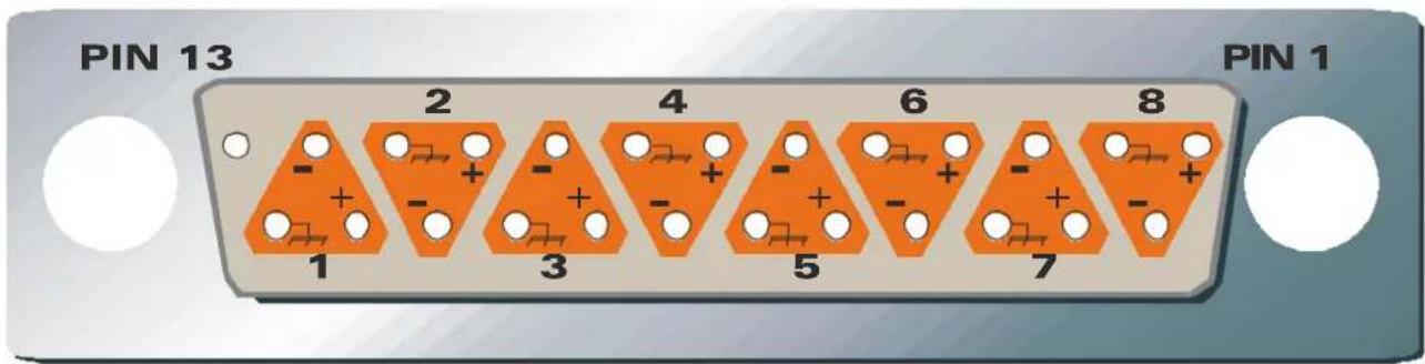
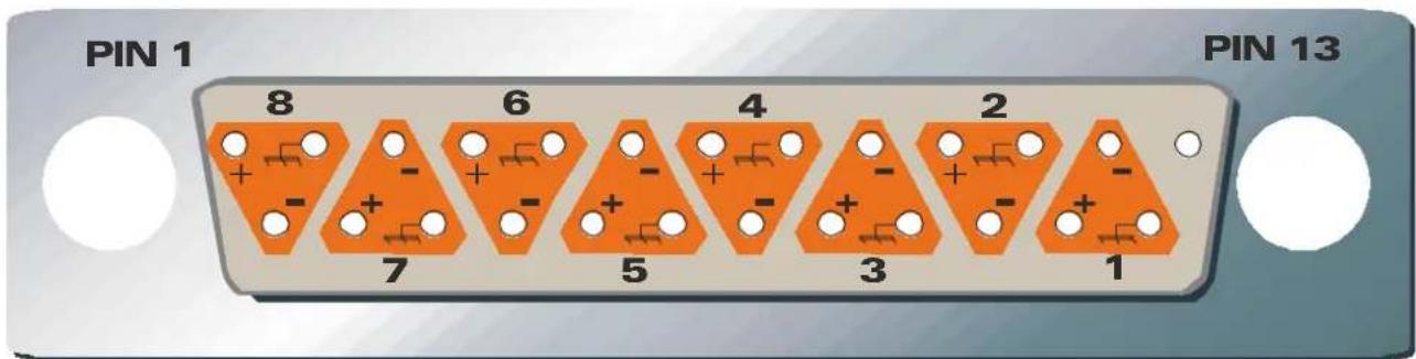
PIN CONVENTIONS
Signal interfaces are provided on 25 pin D Sub type connectors with 4-40 screw thread jack posts. Wiring is in accordance with the DA88 convention. Pin allocations are shown in detail on the next page.
Important: When preparing your D-SUB interface cables please note that the maximum shell size that can be accommodated is 18 x 60mm.
To unbalance the outputs of the ASP510 the -ve Pin should be connected to its adjacent 0v pin at the output of the ASP510 Surround Processing rack unit. Similarly, inputs from unbalanced sources should be connected via twin screened cables with the -ve Pin connection tied to the screen at the unbalanced source.
In order to maintain optimum EMC performance it is important that screens are properly connected at both ends of cable runs.
In this way the electromagnetic shield provided by the equipment chassis and the cable screens will be optimised to reject interference. It is recommended that only high quality braided screen cables are used to avoid compromising EMC performance.
| SIGNAL NUMBER | +VE SIGNAL | -VE SIGNAL | SCREEN |
| D-SUB PIN | |||
| 1 | 2 | 4 | 1 |
| 2 | 1 | 0 | 2 |
| 3 | 2 | 1 | 9 |
| 4 | 7 | 2 | 0 |
| 5 | 1 | 8 | 6 |
| 6 | 4 | 1 | 7 |
| 7 | 1 | 5 | 3 |
| 8 | 1 | 1 | 4 |
| Note: All undesignated pins are unconnected. All screen connections are joined inside the unit and connected to metalwork earth. | |||
WIRING SIDE OF FREE MALE CONNECTOR
WIRING SIDE OF FREE FEMALE CONNECTOR
⑤adient 5/2001
| SIGNAL ASSIGNMENTS | ||||||||||
| 5.1 PLAY A | 5.1 PLAY B | SURROUND BUS INPUTS | DECODEREN | CODERSPEAKERS | CONSOLE INTERFACE | STEREO RECORD/PLAY | 5.1 RECORD A | 5.1 RECORD B | ||
| TYPE | ELECTRONICALLY BALANCED FEMALE D-SUB | ELECTRONICALLY BALANCED FEMALE D-SUB | ELECTRONICALLY BALANCED FEMALE D-SUB | ELECTRONICALLY BALANCED FEMALE D-SUB | GROUND SENSING OFR, ELECTRONICALLY BALANCED INPUTS MALEDSUB | GROUND SENSING MALEDSUB | AUDIO - ELECTRONICALLY BALANCED LOGIC - OPTO-ISOLATED FEMALE D-SUB | ELECTRONICALLY BALANCED FEMALE D-SUB | ELECTRONICALLY BALANCED MALEDSUB | ELECTRONICALLY BALANCED MALEDSUB |
| SIGNAL NUMBER 1 | LEFT | LEFT | LEFT | LEFT | LEFT | LEFT | CONTROL ROOM INPUT LEFT | STEREO A PLAY LEFT | LEFTLEFT | |
| 2 | RIGHT | RIGHT | RIGHT | RIGHT | RIGHT | RIGHT | CONTROL ROOM INPUT RIGHT | STEREO A PLAY RIGHT | RIGHT | RIGHT |
| 3 | CENTRE | CENTRE | CENTRE | CENTRE | CENTRE | CENTRE | GUIDE TRACK INPUT LEFT | STEREO B PLAY LEFT | CENTRE | CENTRE |
| 4 | LFE | LFE | LFE | LFE | LFE | LFE | GUIDE TRACK INPUT RIGHT | STEREO B PLAY RIGHT | LFE | LFE |
| 5 | LEFT SURROUND | LEFT SURROUND | LEFT SURROUND | LEFT SURROUND | LEFT SURROUND | LEFT SURROUND | REMOTE DIM SENSE | STEREO A RECORD LEFT | LEFT SURROUND | LEFT SURROUND |
| 6 | RIGHT SURROUND | RIGHT SURROUND | RIGHT SURROUND | RIGHT SURROUND | RIGHT SURROUND | RIGHT SURROUND | REMOTE SOLO SENSE | STEREO A RECORD RIGHT | RIGHT SURROUND | RIGHT SURROUND |
| 7 | NOT USED | NOT USED | STEREO BUS LEFT | ENCODED OUTPUT LEFT (LT) | ENCODED INPUT LEFT (LT) | LEFT ALTERNATE | REMOTE TALKBACK SENSE | STEREO B RECORD LEFT | NOT USED | NOT USED |
| 8 | NOT USED | NOT USED | STEREO BUS RIGHT | ENCODED OUTPUT RIGHT (Rt) | ENCODED INPUT RIGHT (Rt) | RIGHT ALTERNATE | REMOTE BYPASS | STEREO B RECORD RIGHT | NOT USED | NOT USED |
SIGNAL ASSIGNMENTS

Installation Operation Manual
CONTROL INTERFACES
The ASP510 allows various logic control signals from the host mixing console to be interfaced to allow continued operation of console solos etc. These connections are detailed on the next page and are made via AC/DC floating opto-isolators that will successfully detect any positive or negative going control voltage between 2v and 24v.
Console solo and talkback systems differ widely and the relevant manufacturer should be consulted for details of suitable ways of deriving logic output signals interfacing to the ASP510.
REMOTE CONTROL CONNECTION
The ASP510 Surround Processor rack unit is connected to its remote control via a standard CAT5 data cable which plugs into the REMOTE socket on each unit. A 5m cable is supplied with the unit but any non-reversed CAT5 FTP (sheilded twisted pair) cable may be used. The maximum recommended length of cable is 20m
DEFAULTS
When you first turn on your ASP510 it will load the following default set-up:
MONITOR FORMAT:5.1
ALTERNATE SPEAKERS:OFF
STEREO RECORD SOURCE:BUS
MONITOR SOURCE: SURROUND RECORD
ENCODER/DECODER:OUT
GUIDE:OFF
REF: OFF
REFERENCE LEVEL: -10dB
VOLUME: FULLY COUNTER-CLOCKWISE
DIM: ON
DIM LEVEL: -20dB
CUT: CUT
MODE: CUT
SPEAKERS: ON
MONITOR TRIMS: 0dB
To restore these defaults hold down the Bypass button until it flashes and then release it.
CONFIGURING YOUR INSTALLATION
OVERVIEW
The ASP510 has been designed to allow maximum flexibility in system configuration without compromising either ease of installation or use.
It is important to recognise that the ASP510 can provide comprehensive management of both monitoring and record functions in a Surround environment.
The provision of multiple Surround and Stereo inputs as well as dedicated Encoder/Decoder inserts and comprehensive console interfacing make it easy to configure the system to suit your requirements.
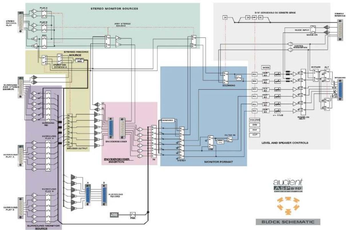
A block system diagram of the ASP510 is provided at the end of this manua. Example configurations are also included as a guide to the ways that the ASP510 can be integrated into a range of Surround systems.
For more detailed general guidance on working in Surround Sound formats, Dolby Laboratories (www.dolby.com) and Surround Associates (www.surroundassociates.com) have many useful guides and publications.
OPTIMISING LEVELS
To ensure the best overall system performance it is important to optimise operating levels.
Generally, interfaces between the ASP510 and recorders, encoders and decoders will be at a nominal level of +4dBu.
Care should be taken in planning the gain structure of the power amplifiers however. Typically, power amplifiers require only around +10dBu for full output. The maximum output of the ASP510 is +24dBu. If you are using a stand-alone crossover or loudspeaker management system it is sensible to optimise the level at this point. However if the ASP510 is driving a power amplifier directly it may be advisable to attenuate the input to the power amplifier using the rotary controls on the amplifier if these are provided or else by a fixed (\~10dB) pad at the amplifiers input.
Note that the monitor trim levels on the front face of the ASP510 Surround Processor rack are not intended for the purpose of providing overall attenuation of the monitor outputs.
In setting the power amplifier gains it is important to consider the operating position of the ASP510 Volume control. The law of this control has been carefully developed to give optimum resolution between the 12.00 o'clock and 5.00 o'clock (fully clockwise) positions. A normal operating position in this range is suggested with use of the DIM control when a lower level range is required.
ROOM SET-UP
It is not within the scope of this manual to deal in detail with room and monitor calibration. The sources noted opposite have useful sections on this topic however.
Monitor calibration is achieved using the built-in Pink Noise generator and the preset level controls on the front panel of the ASP510 Surround Processor rack unit. These are detented in the centre position at unity gain and provide a total range of +/- 10dB.
The internal Pink Noise generator is set so that the level at the speaker outputs will be 0dBu with the ASP510 main volume control fully clock-wise and the speaker trims in their centre detent positions.
When entering set-up mode by activating the Pink Noise generator all speaker cuts are automatically selected to prevent possibly damaging sound pressure levels being generated. The speakers can be unmuted as required by depressing the relevant cut button.
Normally calibration will be carried out in 'REFERENCE' mode and details of how to set this and on using the Pink Noise generator are to be found in 'Functions and Controls' later in this manual.
FUNCTIONS AND CONTROLS

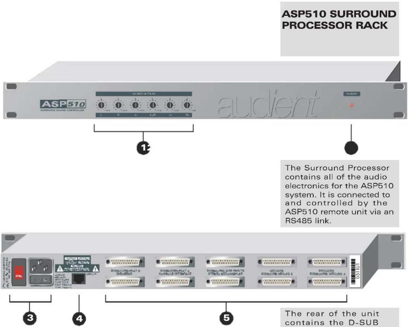
- MONITOR LEVEL trim controls provide adjustment of +/- 10dB for each speaker output.
- POWER on indicator.
-
Mains inlet and voltage selector.
-
Remote control interface - connects via a CAT5 cable to the mating connector on the rear face of the Remote unit.
- Audio and logic interfaces on 25-PIN D-SUB connectors.
Audio interfaces are either electronically balanced or ground-sensing.
Logic interfaces are via AC/DC floating optoisolators.
The rear of the unit contains the D-SUB interfaces for up to six monitor sources, three surround and three stereo. Inserts are also provided for an encoder/decoder.
The Console Interface allows the ASP510 to integrate seamlessly with the host console Solo ,Dim and Talkback logic systems. Provision to connect the console control room outputs also allows these to be fed directly to the Left and Right monitors when working only in stereo with the ASP510 in bypass mode. Using the same interface a Guide or Production track can be routed to the monitors via the ASP510.
The six speaker outputs are each provided with front panel level trim controls.
ASP510 REMOTE CONTROL
FORMAT SELECTION
flowchart
graph TD
    A["1"] --> B["MONITOR FORMAT"]
    C["2"] --> D["STEREO RECORD SOURCE"]
    E["3"] --> F["MODE"]
    B --> G["STEREO"]
    D --> H["STEREO"]
    F --> I["STEREO"]
    G --> J["MONITOR SOURCE"]
    H --> K["MONITOR SOURCE"]
    I --> L["MONITOR SOURCE"]
    J --> M["SURROUND"]
    K --> N["SURROUND SOURCE"]
    L --> O["SURROUND SOURCE"]
    M --> P["SURROUND SOURCE"]
    Q["GUIDE"] --> R["ON"]
    S["VOLUME"] --> T["HEF"]
    U["VOLUME"] --> V["L"]
    U --> W["C"]
    U --> X["R"]
    U --> Y["Ls"]
    U --> Z["Rs"]
    U --> AA["BUP"]
    U --> AB["~"]
    AC["audient: SURROUND CONTROLLER ASP570"]
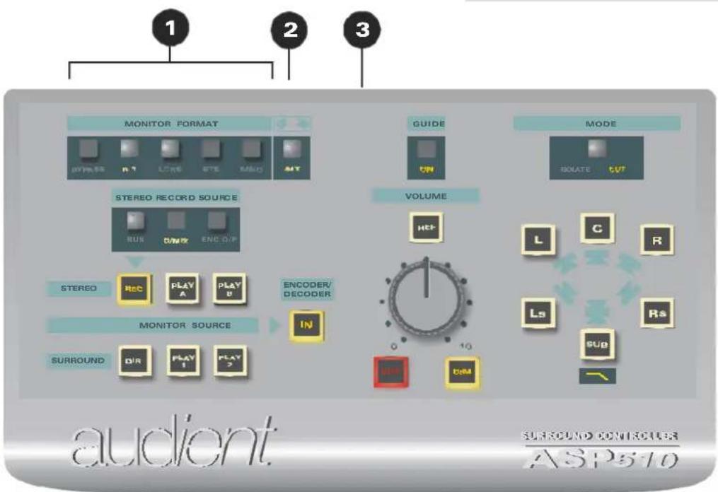
- MONITOR FORMAT is selected using these five switches. An illuminated legend displays the selected choice from 5.1, LCRS, Stereo, Mono and Bypass. All of these format selection buttons are interlocked to automatically cancel the previous selection except Bypass which operates independently.
To set the 5.1 format to FILM mode hold down the 5.1 button until it flashes and then release. To cancel this mode hold down the 5.1 button until it stops flashing.
Bypass sets the entire ASP510 into stereo mode connecting the console control room outputs directly to the Left and Right speakers.
Bypass disables all ASP510 functions other than the Alternate speaker switching (see below). To exit from Bypass mode push the button again.
To restore factory default settings hold down the Bypass button until it flashes and then release it.
-
ALT switches the main Left and Right speaker outputs from the main monitors to the Alternate (usually small near-field) monitors.
-
Remote to Rack unit link connector.
The ASP510 enables the user to select any one of 5 primary monitor formats: 5.1, LCRS, Stereo, Mono or Bypass.
A switchable 120Hz filter is provided for the sub-bass monitor path (see page 12).
A 5.1FILM mode is also implemented with the Left surround and Right surround monitor channels attenuated by 3dB.
Switching for alternate Left and Right speakers is provided along with a Bypass mode enabling monitoring direct from the mixing console or DAW.
If the logic sense ports have been connected to the host mixing console the ASP510 will automatically detect and action console Solo, Dim and talkback commands.
ASP510 REMOTE CONTROL
SPEAKER CONTROL
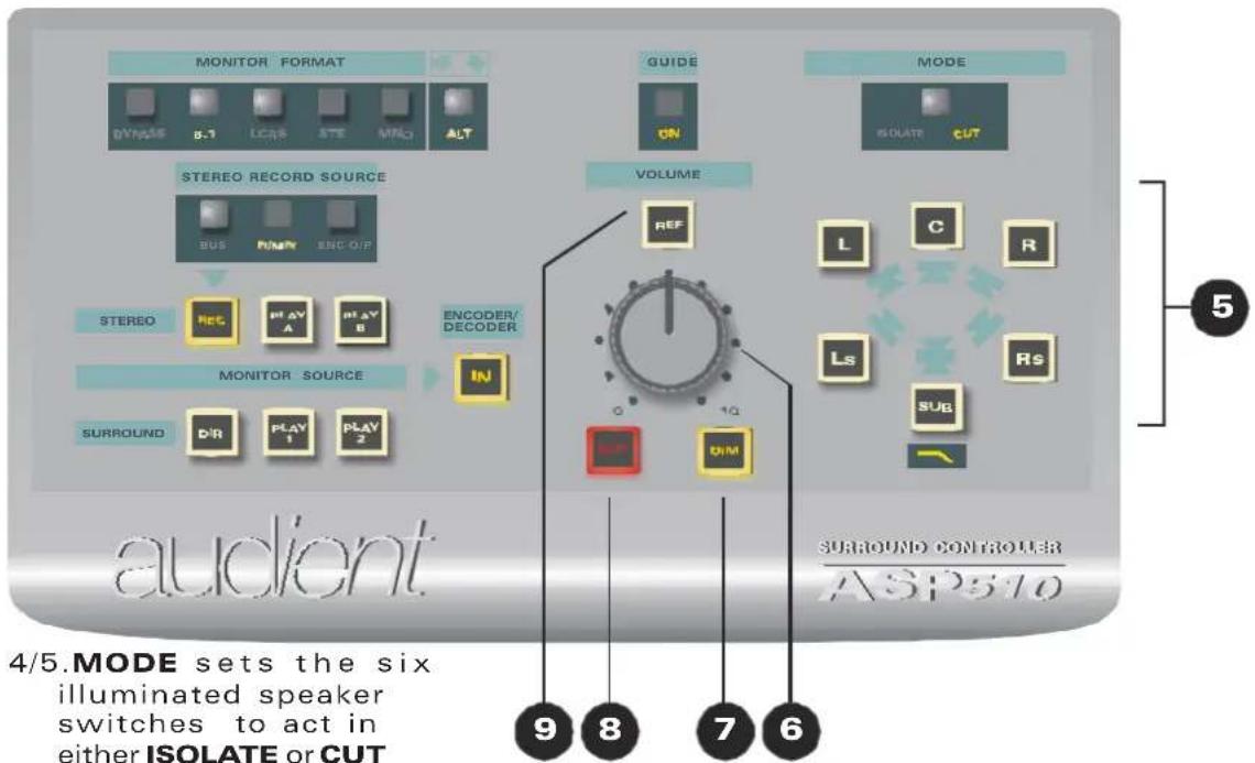
4/5.MODE sets the six
illuminated speaker switches to act in either ISOLATE or CUT mode. An illuminated legend shows which mode is active. The 120Hz low pass filter in the sub-woofer path is activated by holding down the illuminated SUB speaker switch until the filter legend illuminates. To bypass the filter push again until the legend is extinguished.
- The main monitor VOLUME control.
- DIM allows all monitor speakers to be attenuated by a user-settable amount. To set the DIM Level hold down the DIM button until it flashes, release it, set the required level with the main volume control and then push DIM again to store the setting.
8.CUT mutes all monitor speakers.
9.REF sets all monitor
levels to a user - definable reference level independent of the volume control setting. To set the Reference Level hold down the REF button until it flashes, release it, set the required level using the main Volume Control and then push REF again to store the setting.
7/8To turn on the PINK
NOISE generator hold down both the CUT and DIM buttons simultaneously until they flash and then release them. All monitors are now cut but can be unmuted individually for alignment. To turn off the Pink Noise generator push either the CUT or DIM button.
The main Volume control operates via high precision Digital Attenuators to adjust the level of all speaker outputs. Cut and Dim controls are also provided with the Dim level being user settable.
The monitors may also be set to a user predetermined reference level using the REF switch - the volume control is then bypassed.
Each of the six speaker outputs has an individual twin mode illuminated switch. These can be set to operate either as Isolate or Cut switches by using the associated mode switch.
To make system setup straight forward the ASP510 has a built in Pink Noise generator.
ASP510 REMOTE CONTROL
SOURCE SELECTION
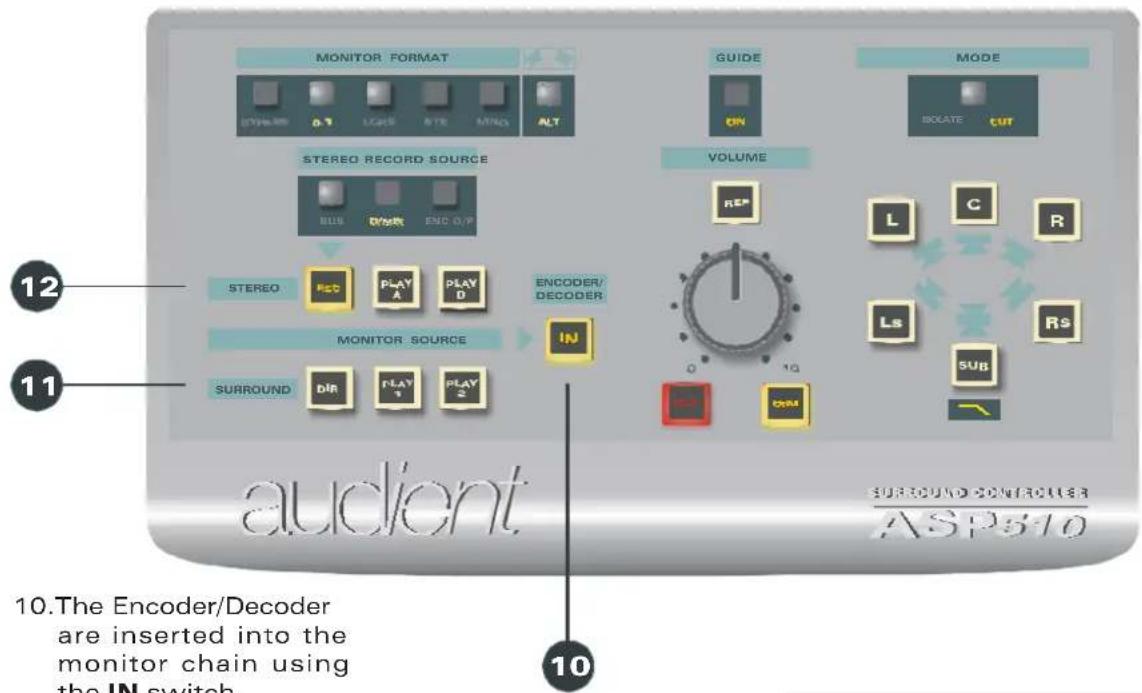
11/12. Three Stereo and three Surround MONITOR SOURCES
are provided. REC selects the 'direct' bus signal from the console or DAW. PLAY A and PLAY B may be any external signal, but typically the recorder returns.
Three interlocking modes can be set independently for the Stereo and Surround sources but note that selecting any Stereo source always cancels a previously selected Surround source and vice versa.
The Default interlock mode causes each Stereo source to automatically cancel any other Stereo source. The same logic applies to the Surround sources. Two additional modes, Lock and Gang are provided.
To LOCK a Stereo (or Surround) source, hold down the relevant select button until it stops flashing. This source is now Locked and will always be active when any Stereo (Surround) source is selected. To lock a second or third source simply repeat this action. To cancel, hold down the button until it extinguishes.
ToGANG together two or more of the Stereo (or Surround) sources, hold down the first member of the Gang until it flashes then release it and hold down the second member until it too flashes and release it. The third source can be added to the gang in the same way. To release members from the Gang hold down the relevant source select until it extinguishes and then release it.
THE ASP510 allows three surround (up to 5.1) and three stereo sources to be monitored.
The source selections can be set to interlock in three ways: Normal, Lock and Gang.
Normal mode provides the usual self cancelling selection interlocks.
Lock allows one or more of the sources (eg a dialogue stem) to be permanently selected.
Gang provides a simple method of 'grouping' two or more sources or stems so that they can be selected together with a single button push.
An encoder/decoder pair can be switched into the monitoring chain for confidence checking material intended to be distributed in Dolby Surround format for example.
ASP510 REMOTE CONTROL
SOURCE SELECTION

13. The source for the
STEREO RECORDERS
can be selected as the Stereo BUS feed from the console or DAW, a
DOWNMIX of the
Direct Surround source or the LtRt output of the
ENCODER. Illuminated legends show which source has been selected.
14. GUIDE en a b l e s a
production track to be input directly to the main Left and Right monitors. An associated ON legend is illuminated when the Guide input is active.
A guide or production track may be switched directly into the Left and Right monitor speakers when mixing to picture for instance.
As well as providing monitor source selection the ASP510 enables the source for the stereo recorder sends to be selected from either the console (or DAW) stereo output, a downmix of the direct surround source or the LtRt output of the encoder.
SPECIFICATIONS
LEVELS
Nominal levels+4dBu
Maximum input+24dBu
Maximum output+24dBu
FREQUENCY RESPONSE
Any input to any output+/-0.25dB22Hz -22kHz
THD AND NOISE
Any input to any output<0.003%@+4dBu, 1kHz
NOISE
At speaker outputs<-92dBu22Hz - 22kHz
CROSSTALK
(Source/source)>80dB1kHz
CHANNEL TRACKING
+/-0.25dB0 to-24dB
SYSTEM INTERFACES
25pin D-type females for:
5.1 Surround play A and B
5.1 Surround bus inputs
Stereo record/transmission & play
Console interface
Decoder
25pin D-type males for:
5.1 Surround record A and B
Speaker outputs
Encoder
RJ45 for remote/rack link.
SIZES:
Rack unit: 1U x 280mm
POWER REQUIREMENTS:
115/230v @50/60Hz (50VA)
Remote:W230mm
D 120mm
H 40mm
WARRANTY
Your ASP500 series Controller comes with a manufacturer's warranty for one year from the date of despatch to the end user.
The warranty covers faults due to defective materials used in manufacture and faulty workmanship only.
During this warranty period Audient will repair or at its discretion replace the faulty unit provided it is returned carriage paid to an authorised Audient service centre.
We will not provide warranty repair if in our opinion the fault has resulted from unauthorised modification, misuse, negligence, act of God or accident.
We accept a liability to repair or replace your ASP510 as described above. We do not accept any additional liability.
This warranty does not affect any legal rights you may have against the person who supplied this product – it is additional to those rights.
flowchart
graph TD
    A["STUDIO"] --> B["PLA A"]
    A --> C["PLA B"]
    A --> D["PLA C"]
    A --> E["PLA D"]
    A --> F["PLA E"]
    A --> G["PLA F"]
    A --> H["PLA G"]
    A --> I["PLA H"]
    A --> J["PLA I"]
    A --> K["PLA J"]
    A --> L["PLA K"]
    A --> M["PLA L"]
    A --> N["PLA M"]
    A --> O["PLA N"]
    A --> P["PLA O"]
    A --> Q["PLA P"]
    A --> R["PLA Q"]
    A --> S["PLA R"]
    A --> T["PLA S"]
    A --> U["PLA T"]
    A --> V["PLA U"]
    A --> W["PLA V"]
    A --> X["PLA W"]
    A --> Y["PLA X"]
    A --> Z["PLA Y"]
    A --> AA["PLA Z"]
    A --> AB["PLA AA"]
    A --> AC["PLA AB"]
    A --> AD["PLA AC"]
    A --> AE["PLA AD"]
    A --> AF["PLA AE"]
    A --> AG["PLA AF"]
    A --> AH["PLA AG"]
    A --> AI["PLA AH"]
    A --> AJ["PLA AI"]
    A --> AK["PLA AJ"]
    A --> AL["PLA AK"]
    A --> AM["PLA AL"]
    A --> AN["PLA AM"]
    A --> AO["PLA AN"]
    A --> AP["PLA AO"]
    A --> AQ["PLA AP"]
    A --> AR["PLA AU"]
    A --> AS["PLA AU"]
    A --> AT["PLA AU"]
    A --> AU["PLA AU"]
    A --> AV["PLA AU"]
    A --> AW["PLA AU"]
    A --> AX["PLA AU"]
    A --> AY["PLA AU"]
    A --> AZ["PLA AU"]
    A --> BA["PLA AU"]
    A --> BB["PLA AU"]
    A --> BC["PLA AU"]
    A --> BD["PLA AU"]
    A --> BE["PLA AU"]
    A --> BF["PLA AU"]
    A --> BG["PLA AU"]
    A --> BH["PLA AU"]
    A --> BI["PLA AU"]
    A --> BJ["PLA AU"]
    A --> BK["PLA AU"]
    A --> BL["PLA AU"]
    A --> BM["PLA AU"]
    A --> BN["PLA AU"]
    A --> BO["PLA AU"]
    A --> BP["PLA AU"]
    A --> BQ["PLA AU"]
    A --> BR["PLA AU"]
    A --> BS["PLA AU"]
    A --> BT["PLA AU"]
    A --> BU["PLA AU"]
    A --> BV["PLA AU"]
    A --> BW["PLA AU"]
    A --> BX["PLA AU"]
    A --> BY["PLA AU"]
    A --> BZ["PLA AU"]
BLOCK SCHEMATIC

APPLICATION NOTES
