
NSW-R4 - Router Gembird - Free user manual and instructions
Find the device manual for free NSW-R4 Gembird in PDF.


| Product Type | Router |
| Model | NSW-R4 |
| Brand | Gembird |
| Dimensions (W x D x H) | 150 x 100 x 30 mm |
| Weight | 0.2 kg |
| Power Supply | 5V DC, 1A (via micro USB) |
| Wireless Standards | IEEE 802.11 b/g/n |
| Frequency Band | 2.4 GHz |
| Maximum Wireless Speed | 150 Mbps |
| Wired Ports | 1 x WAN, 4 x LAN (10/100 Mbps) |
| Security Features | WEP, WPA/WPA2, firewall, MAC filtering |
| LED Indicators | Power, WAN, LAN (1-4), WLAN |
| Reset Button | Yes, pinhole reset |
| Antenna Type | Fixed internal antenna |
| Operating Temperature | 0°C to 40°C |
| Storage Temperature | -20°C to 60°C |
| Humidity | 10% to 90% (non-condensing) |
| Maintenance | Clean with dry cloth; avoid liquids |
| Spare Parts | Power adapter available separately |
| Repairability | Not user-serviceable; contact support |
Frequently Asked Questions - NSW-R4 Gembird
User questions about NSW-R4 Gembird
0 question about this device. Answer the ones you know or ask your own.
Ask a new question about this device
Download the instructions for your Router in PDF format for free! Find your manual NSW-R4 - Gembird and take your electronic device back in hand. On this page are published all the documents necessary for the use of your device. NSW-R4 by Gembird.
USER MANUAL NSW-R4 Gembird
natural_image
Abstract logo design featuring a stylized arrow and 'GE' letters, no readable text or symbols beyond the graphic elements.GEMBIRD®
natural_image
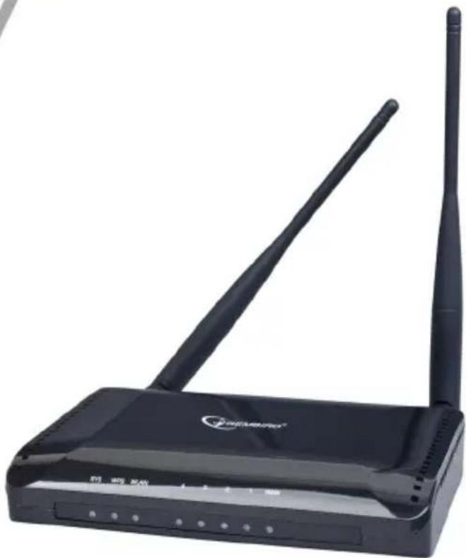
Black wireless router device with two antennas and a brand logo (no visible text or symbols on the device body)WIRELESS BROADBAND ROUTER, 300 M
- Wireless 300M router with 4-port 10/100Mbps LAN switch and 802.11n access point
• Supports all IEEE802.11b/g/n WiFi standards - Up to 300 Mbps data transfer rate via the wireless 802.11n protocol
- Built-in DHCP server automatically assigns and manages all IP addresses within your LAN
• Advanced firewall, 64/128-bit WEP encryption and WPA-PSK, WPA2-PSK security
• Supports Wi-Fi Protected Setup (WPS) with reset button
• Supports MAC/IP filtering and URL blocking (family filter) - Easy to use Web-interface for all router management options
Specifications
- Supported standards: IEEE 802.11n, IEEE 802.11g, IEEE 802.11b, IEEE 802.3, IEEE 802.3u, CSMA/CA,CSMA/CD, TCP/IP, DHCP, ICMP, NAT, PPPoE, PPTP
- Ports: - LAN: 4 x 10/100M Auto MDI/MDIX RJ45 ports
• WAN: 1 x 10/100M Auto MDI/MDIX RJ45 port
• Frequency band 2.4 \~ 2.4835GHz
• Channels: 1 \~ 11 (US, Canada), 1 \~ 13 (Europe)
• Supports Virtual Server and DMZ
• Supports DDNS (DynDNS, TZO) and QoS
• Data transfer rates: max 300 Mbps (11n), 54 Mbps (11g), 11 Mbps (11b) - Encryption standards: WPS, WPA, WPA2, WPA2/WPA Mixed
• Antenna: 2 x 3 Dbi omni-directional antenna
• RF power: 20 dBm (max)
• Transmission distance: indoors up to 120 m, outdoors up to 360 m (distance is dependent of environmental conditions, obstructions, walls, ceilings, etc)
• Dimensions: 153 x 100 x 30 mm (W x D x H)
• Operating temperature: 0 \~ 40 °C
• Storage temperature: -40 \~ 70 °C - Operating humidity: 10 \~ 90 % non-condensing;
• Storage humidity: 5 \~ 95 % non-condensing

1. Wireless router overview
1.1 Front panel (LED indicators)

SYS (Red): Flickering light indicates a proper connection to the power supply.
WPS (Green): The LED is flash about two minutes during WPS working.
WLAN (Green): The LED is flickering during wireless activity.
LAN 1, 2, 3, 4(Green): The Link/Act LED serves two purposes. If the LED is continuously illuminated, the Router is successfully connected to a device through the corresponding port. If the LED is flickering, the Router is actively sending or receiving data over that port.
WAN (Green): The Link/Act LED serves two purposes. If the LED is continuously illuminated, the Router is successfully connected to a device through the corresponding port. If the LED is flickering, the Router is actively sending or receiving data over that port.
1.2 Back panel (sockets description)

WAN: 10/100Mbps RJ45 port. The WAN port is where you will connect Cable/DSL Modem or other LAN.
LAN (1, 2, 3, 4): 10/100Mbps RJ45 Auto-sensing. These four LAN ports are where you will connect networked devices, such as PCs, print servers, remote hard drives, and anything else you want to put on your network. If you connect this product with the Hub (or Switchboard) correctly, the Router's corresponding LED and the Hub's (or the Switchboard's) must be illuminates.
POWER: Power inlet.
RESET (WPS): The Reset Button has two functions, WPS and Factory Default. When press it less than 2 seconds, it is WPS function and the Reset LED will flash two minutes, than 6 seconds, the router will restore to factory default.
2 Hardware Installation

flowchart
graph TD
    A["Wireless PCMCIA Adapter"] -->|Wireless Signal| B["Cable/DSL Modem"]
    C["Wireless PCI Adapter"] -->|Wireless Signal| D["11n Router"]
    B --> E["Power"]
    D --> E
    E --> F["Internet"]
- Make sure that all devices including your PCs, modem and router are powered off.
-
Connect your Internet access device such as cable or DSL modem to the router WAN port using a cat 5e patch cord.
-
Turn all the devices on.
- Power the router up.
3 Quick Installation Guide
3.1 TCP/IP Settings
Before you can access and configure router, you have to setup your PC network adapter IP address. Connect your PC to the router LAN port. Follow the steps below to access the built-in router web-interface (for Windows OS).
Note: The router default IP address is: 192.168.1.1
- Choose Network connections from the Control Panel.
- Click with the right mouse button over the Network adapter connected to the router. Choose properties from the popup menu which would then appear.
- Select TCP/IP v.4 from the next window and click Properties
- Select "Obtain an IP address automatically" and "Obtain DNS server address automatically" in the IP Address tab.
- Click OK to complete the install procedure. You might need to restart your PC to activate these settings.
You can verify that your PC got correct IP address selecting Start → Run → cmd and then entering command: ipconfig /all.

3.2 Getting Started
To access the router web-interface, open a web-browser such as Internet Explorer and enter the IP address of the router (192.168.1.1).

You will be prompted to enter the login and password. The default Login/Password is: admin/admin
Upon a successful login you will see the status page.
| Status | Statistics | Log | |
| Wizard | System | ||
| Operation Mode | Uptime | 0day:16h:31m:56s | |
| WAN Setup | Current Time | 1:21:2 8/14 2009 | |
| Firmware Version | v1.00.07 | ||
| LAN Setup | Build Time | Thu Aug 13 08:49:08 HKT 2009 | |
| Wireless Setup | Wireless Configuration | ||
| Services Setup | Mode | AP | |
| Band | 2.4 GHz (B+G+N) | ||
| SSID | 802.11N | ||
| Security Setup | Channel Number | 6 | |
| Encryption | Disabled | ||
| Router Setup | BSSID | 00:e0:4c:80:90:b1 | |
| Associated Clients | 0 | ||
| QoS Setup | TCP/IP Configuration | ||
| System | Attain IP Protocol | Fixed IP | |
| IP Address | 192.168.1.1 | ||
| Subnet Mask | 255.255.255.0 | ||
| Status | DHCP Server | Enabled | |
| MAC Address | 00:e0:4c:80:90:b1 | ||
| Logout | WAN Configuration | ||
| Attain IP Protocol | DHCP | ||
| IP Address | 192.168.10.124 | ||
| Subnet Mask | 255.255.255.0 | ||
| Default Gateway | 192.168.10.1 | ||
| Primary DNS | 61.187.98.3 | ||
| Secondary DNS | 202.103.96.112 | ||
| MAC Address | 00:e0:4c:80:90:b2 | ||
3.3 Setup Wizard
Click on the "Wizard" option to setup your router step by step in a simple way. There are six steps to follow:
Wizard
Wizard Settings
The setup wizard will guide you to configure this router for first time. Please follow the setup wizard step by step.
- Setup Operation Mode
- Choose your Time Zone
- Setup LAN Interface
- Setup WAN Interface
- Wireless LAN Setting
- Wireless Security Setting
Next>>
Please follow the steps to complete the router configuration.
Step 1 – Operation Mode Settings
The router supports three operation modes: Gateway, Bridge and Wireless ISP. Each mode is suitable for different purpose, please choose the correct mode.
Wizard
Wizard --> Operation Mode Settings
You can setup different modes to LAN and WLAN interface for NAT and bridging function.

Gateway
In this mode, the device is supposed to connect to internet via ADSL/Cable Modem. The NAT is enabled and PCs in four LAN ports share the same IP to ISP through WAN port. The connection type can be setup in WAN page by using PPPOE, DHCP client, PPTP client, L2TP client or static IP.

Bridge
In this mode, all ethernet ports and wireless interface are bridged together and NAT function is disabled. All the WAN related function and firewall are not supported.

Wireless ISP
In this mode, all ethernet ports are bridged together and the wireless client will connect to ISP access point. The NAT is enabled and PCs in ethernet ports share the same IP to ISP through wireless LAN. You must set the wireless to client mode first and connect to the ISP AP in Site-Survey page. The connection type can be setup in WAN page by using PPPOE, DHCP client, PPTP client, L2TP client or static IP.
Cancel
<<Back
Next>>
Step 2 – Time Zone Settings
The Time Configuration option allows you to configure, update, and maintain the correct time for the internal system clock. Daylight Saving can also be configured to automatically adjust the time when needed.
Wizard
Wizard --> Time Zone Settings
You can maintain the system time by synchronizing with a public time server over the Internet.
NTP client update
Automatically Adjust Daylight Saving

Enable
Time Zone Select
(GMT)Casablanca, Monrovia
NTP server

Enable
192.5.41.41 - North America
Cancel

<<Back
Next>>
NTP client update: Check this box to connect to the NTP Server and synchronize Internet time.
Automatically Adjust Daylight Saving: If you check this box the system will take the summer time into consideration.
Time Zone Select: Select the Time Zone from the drop-down menu.
NTP Server: Select the NTP Server from the drop-down menu.
Step 3 – LAN Settings
Setup the IP address and network mask for the LAN interface.
Wizard
Wizard --> LAN Settings
This page is used to configure the parameters for local area network which connects to the LAN port of your Access Point. Here you may change the setting for IP address, subnet mask, DHCP, etc..
IP Address
192.168.1.1
Subnet Mask
255.255.255.0
Cancel
<<Back
Next>>
Step 4 – WAN Settings
The router supports five access modes for the WAN, please choose the correct mode according to your Internet Service Provider (ISP).
Mode 1: DHCP Client
Wizard
Wizard --> WAN Settings
This page is used to configure the parameters for Internet network which connects to the WAN port of your Access Point. Here you may change the access method to static IP, DHCP, PPPoE, PPTP or L2TP by click the item value of WAN Access type.
WAN Access Type
DHCP Client
Cancel
<<Back
Next>>
Select DHCP Client to obtain IP Address automatically from your ISP. This mode is commonly used for Cable modem services.
Mode 2: Static IP
Select Static IP Address if the IP information is provided to you by your ISP. You will need to enter the IP address, subnet mask, gateway address, and DNS address (-es) provided to you by your ISP. Each IP address entered in the fields must be in the appropriate IP form, which are four octets separated by a dot (x.x.x.x). The router will not accept the IP address if it is not in this format.
IP Address: Enter the IP address assigned by your ISP
Subnet Mask: Enter the Subnet Mask assigned by your ISP.
Default Gateway: Enter the Gateway assigned by your ISP.
DNS: The DNS server information will be supplied by your ISP (Internet Service Provider.)
Wizard
Wizard --> WAN Settings
This page is used to configure the parameters for Internet network which connects to the WAN port of your Access Point. Here you may change the access method to static IP, DHCP, PPPoE, PPTP or L2TP by click the item value of WAN Access type.
WAN Access Type
IP Address
Subnet Mask:
Default Gateway
DNS
Static IP

192.168.10.10
255.255.255.0
192.168.10.1
Cancel
<<Back
Next>>
Mode 3: PPPoE
Choose PPPoE (Point to Point Protocol over Ethernet) if your ISP uses a PPPoE connection. Your ISP will provide you with a username and password. This option is typically used for DSL services.
Wizard
Wizard --> WAN Settings
This page is used to configure the parameters for Internet network which connects to the WAN port of your Access Point. Here you may change the access method to static IP, DHCP, PPPoE, PPTP or L2TP by click the item value of WAN Access type.
WAN Access Type
PPPoE

User Name
natural_image
Two empty rectangular boxes with no text or symbolsPassword
Cancel
<<Back
Next>>
User Name: Enter your PPPoE user name.
Password: Enter your PPPoE password.
Mode 4: PPTP
Choose PPTP (Point-to-Point-Tunneling Protocol) if your ISP uses a PPTP connection. Your ISP will provide you with IP information and PPTP
Server IP Address, of course it also includes a username and password. This mode is typically used for DSL services.
Wizard
Wizard --> WAN Settings
This page is used to configure the parameters for Internet network which connects to the WAN port of your Access Point. Here you may change the access method to static IP, DHCP, PPPoE, PPTP or L2TP by click the item value of WAN Access type.
WAN Access Type
PPTP

IP Address
0.0.0.0
Subnet Mask
0.0.0.0
Server IP Address
0.0.0.0
User Name
Password
Cancel
<<Back
Next>>
IP Address: Enter the IP address.
Subnet Mask: Enter the subnet Mask.
Server IP Address: Enter the PPTP Server IP address provided by your ISP.
User Name: Enter your PPTP username.
Password: Enter your PPTP password.
Mode 5 L2TP
Choose L2TP (Layer 2 Tunneling Protocol) if your ISP uses a L2TP connection. Your ISP will provide you with a username and password.
Wizard
Wizard --> WAN Settings
This page is used to configure the parameters for Internet network which connects to the WAN port of your Access Point. Here you may change the access method to static IP, DHCP, PPPoE, PPTP or L2TP by click the item value of WAN Access type.
WAN Access Type
L2TP

IP Address
0.0.0.0
Subnet Mask
0.0.0.0
Server IP Address
0.0.0.0
User Name
Password
Cancel
<<Back
Next>>
IP Address: Enter the IP address.
Subnet Mask: Enter the subnet Mask.
Server IP Address: Enter the PPTP Server IP address provided by your ISP.
User Name: Enter your PPTP username.
Password: Enter your PPTP password.
Step 5 – WLAN Settings
Wizard
Wizard --> Wireless Basic Settings
This page is used to configure the parameters for wireless LAN clients which may connect to your Access Point.
Wireless interface
Band
mode
Network TYPE
SSID
Channel width
ControlSideband
Channel Number

Disable
2.4 GHz (B+G+N)
AP

Infrastructure

802.11N
20MHz

Upper

6

Cancel
<<Back
Next>>
Wireless Interface: If you do not want to use the wireless interface, uncheck the box to disable all the wireless functions.
Band: Supported 802.11B, 802.11G, 802.11N and mixed.
Mode: Supported AP, Client, WDS and AP+WDS mode.
Network TYPE: This type is only valid in client mode.
SSID: Service Set Identifier, external name of your wireless network.
Channel width: Select 40MHz if you use 802.11n or 802.11n mixed mode, otherwise 20MHz, it is default value.
Control Sideband: it is only valid when you choose channel width 40MHz.
Channel Number: Indicates the channel setting for the router. By default the channel is set to 6.
Step 6 – WLAN Security Settings
Secure your wireless network by turning on the WPA or WEP security feature of the router. You can set WEP and WPA-PSK security mode.
The following picture shows how to set the WEP security.
Wizard
Wizard --> Wireless Security Settings
This page allows you setup the wireless security. Turn on WEP or WPA by using Encryption Keys could prevent any unauthorized access to your wireless network.
Encryption
WEP

Key length
64-bit

Key Format
ASCII (5 characters)

Key Setting
*****
Cancel
<<Back
Finished
Key length: WEP supports 64-bit or 128-bit security key.
Key Format: The key can be entered in ASCII (as symbols) or Hex (hexadecimal) format.
Key Setting: Enter the key as ASCII or Hex.
The following picture shows how to set the WPA-PSK security; you can also select WPA (TKIP), WPA2 (AES) and Mixed mode.
Wizard
Wizard --> Wireless Security Settings
This page allows you setup the wireless security. Turn on WEP or WPA by using Encryption Keys could prevent any unauthorized access to your wireless network.
Encryption
Pre-Shared Key Format
Pre-Shared key
WPA2 Mixed
Passphrase

Cancel
<<Back
Finished
Pre-Shared Key Format: Specify the format of the key, pass phrase or hex.
Pre-Shared Key: Enter the key here (phrase or hexadecimal).
4 Advanced Setup
4.1 Wireless Advanced setup
4.1.1 WPS
WPS is designed to set up the password-protected Wi-Fi networks and to simplify the network management. This router supports WPS features for AP mode (access point), AP+WDS mode, Infrastructure-Client mode, and the wireless root interface of Universal Repeater mode.
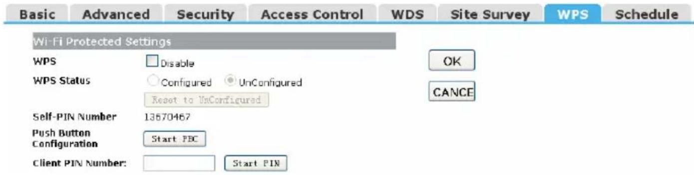
WPS: Checking this box and clicking "OK" will disable the WPS function. WPS is turned on by default.
WPS Status: After you set up all security settings the checkbox "Configured" will be highlighted
Self-PIN Number: It is AP's PIN number.
Start PBC: Clicking this button will invoke the Pus Button Configuration of WPS. If one station wants to connect to the AP, it must click its PBC button within two minutes. You will see the reset LED flashing during this time.
Note: This router also has a hardware button, it is the same button with reset. If you keep this button pressed for less than two seconds, the AP will run the PBC function. The reset LED will then flash for two minutes. During this time, the workstations can connect to the AP by using their software or hardware WPS button.
Client PIN Number: The length of PIN can be four or eight digits. If the AP and the workstation use this PIN, they will establish a connection and setup their security key.
4.1.2 Access Control
The Wireless MAC Address Filtering feature allows you to control which wireless stations are allowed to be connected to the router.
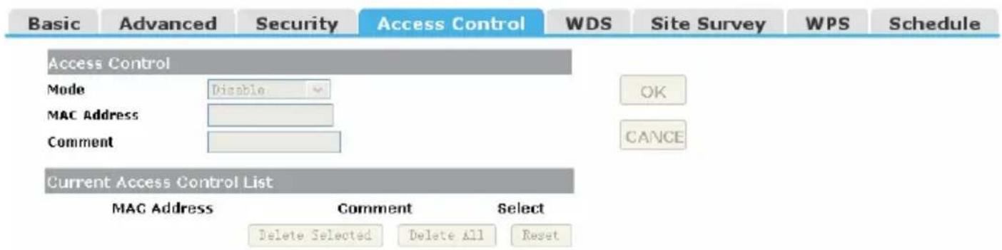
Mode: If you choose 'Allowed Listed', only those clients whose wireless MAC addresses are in the access control list will be able to connect to your Access Point. When 'Deny Listed' is selected, these wireless clients on the list will not be able to connect the Access Point. The MAC Address format is 001122334455.
4.1.3 WDS
Wireless Distribution System uses wireless media to communicate with the other APs. To do this, you should first set AP Mode to WDS or AP+WDS in the basic settings, then enable WDS function and set another AP MAC address which you would like to communicate with. The WDS supports WEP and PSK security mode. Of course in order to make the APs work, you have to assign for them the same channel and security mode.

WDS: Check this box to enable the WDS function.
MAC Address: Enter the remote AP MAC address.
Security: Sets the WDS security settings.
Encryption: You may select WEP 64bits, WEP 128bits, WPA (TKIP), WPA (AES).
WEP Key Format: You may select ASCII Characters or Hexadecimal Digits (in the "A-F", "a-f" and "0-9" range) to be the WEP Key.
WEP Key: Set key to encrypt your data
Pre-Shared Key Format: You can select PASSPHRASE or HEX(64 CHARACTERS).
Pre-Shared Key: Pre-shared key(PSK) is a method to set encryption keys. Commonly used in Wi-Fi Protected Access and WEP.
4.2 Service Setup
4.2.1 Port Forwarding
If you configure the router as Virtual Server, remote users accessing services such as Web or FTP at your local site via public IP addresses can be automatically redirected to the local servers with private IP addresses. In other words, depending on the requested service (TCP/UDP port number), the router redirects the external service request to the appropriate server.
Port Forwarding
Trigger Port
DMZ
UPnP
Port Forwarding
Status
IP Address
Protocol
Port Range
Comment

Enable

Both
The image contains no text or characters.
Current Port Forwarding Table
| Local IP Address | Protocol | Port Range | Comment | Select |
DELETE SELECTED
DELETE ALL
CANCEL
Status: Clicking this box will enable the Port Forwarding function.
IP Address: The external public IP address to be redirected.
Protocol and Port Range: Select the protocol and port range to be redirected to the local IP.
Current Filter Table: The table shows all forwarding records you have added so far. You can delete any selected record or all records at once.
4.2.2 Trigger Port
Some applications (like Internet games, video conferencing, Internet calling and so on) require multiple connections. These applications cannot work with a pure NAT router. Port Triggering is used for some of these applications to let them work with a NAT router.

Status: Check on to enable this function.
Trigger Port Range: The port for outgoing traffic. An outgoing connection using this port will "Trigger" this rule.
Trigger Protocol: The protocol used for Trigger Ports, either TCP, UDP or both.
Incoming Port Range: The port or port range used by the remote system when it responds to the outgoing request. A response using one of these ports will be forwarded to the PC that triggered this rule.
Incoming Protocol: The Protocol used for Incoming Ports Ranges, either TCP or UDP, or both.
Comment: You can add some comments for this item.
4.2.3 DMZ
If you have a client PC that cannot run Internet applications properly from behind the NAT firewall or after configuration of the Port Forwarding, then you can open the client to unrestricted two-way Internet access.
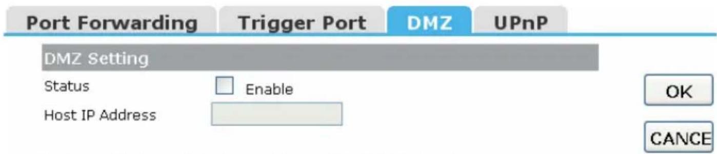
Status: Clicking this box will enable DMZ function.
Host IP Address: Enter the DMZ host IP Address. Note: this may expose this computer to a variety of security risks.
4.2.4 UPNP
The Universal Plug and Play (UPnP) feature allows the devices, such as Internet computers, to access the local host resources or devices as needed,
UPnP devices can be automatically discovered by the UPnP service application on the LAN.

UPnP: Check to enable UPnP function
Note: The list will contain the forwarding port added by the UPnP Service.
4.3 Security Setup
The router provides extensive firewall settings to limit the risk of intrusion and protect your computer from hacker attacks.
4.3.1 Security
The firewall will allow or block some services according to the following settings.
Security
Access Control
DoS
Security
Ping Access on WAN
IGMP Proxy
Web Server Access on WAN
IPsec pass through
PPTP pass through
L2TP pass through
Enable
Enable
Enable
Enable
Enable
Enable
OK
CANCE
Ping Access on WAN: allows or blocks the Ping WAN interface.
IGMP Proxy: IGMPproxy is a simple dynamic Multicast Routing Daemon using only IGMP signaling. It's intended for simple forwarding of Multicast traffic between networks.
Web Server Access on WAN: allow or blocks access to the Web Server from WAN interface.
VPN pass through: allows or blocks the VPN Pass through the router NAT.
4.3.2 Access Control
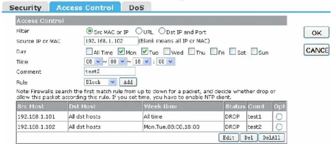
You can set up some rules, for example MAC filter, IP filter, URL filter and Port filter. You can also add some extra conditions for these rules (the date and time), but then you should enable the NTP-client first.
Note 1: Whenever a network packet arrives, the firewall will try to find a suitable rule from this table. The search goes from up to down and stops when a match has been found. Then the packet will be either forwarded or
dropped according to the rule. If no rule matching the packet is found, then the firewall will let it go to the destination.
Note 2: If you set the date and time in your rule then the NTP client has to be enabled.
Note 3: Click "Add" button to add this rule to the table and click "OK" to make it effective. You also can edit or delete the records:
1. IP Filter
Allow or block the computers according to their IP addresses.
2. MAC filter
Allow or block the computers according to their MAC addresses.

3. URL filter
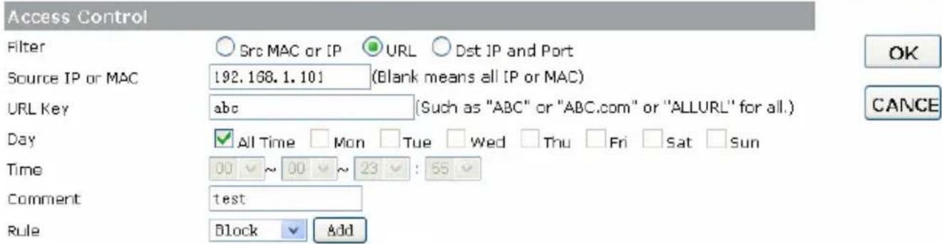
You can block some URLs using the URL Key string. If Source IP or MAC address fields are blank, then all computers can not access this URL, otherwise the rule only applies to the computer with the given IP or MAC address.
Example 1: block "abc.com", "abc.net" or "www.abc.com" to all computers.
Security
Access Control
DoS

Note: Firewalls search the first match rule from up to down for a packet, and decide whether drop or allow this packet according this rule. If you set time, you have to enable NTP client.
| Src Host | Dst Host | Week time | Status | Comt | Opt |
| All src hosts | abc | All time | DROP | test | Og |
| EditDelDelAll | |||||
Example 2: block “abc.com”, “abc.net” or “www.abc.com” for the computer with 192.168.1.101 IP address.
Security
Access Control
DoS
Note: Firewalls search the first match rule from up to down for a packet, and decide whether drop or allow this packet according this rule. If you set time, you have to enable NTP client.
| Src Host | Dst Host | Week time | Status | Comt | Opt |
| 192.168.1.101 | abc | All time | DROP | test | Og |
| EditDelDelAll | |||||
Example 3: allow to access “abc.com”, “abc.net” or “www.abc.com” for all computers from 09:00 to 18:00 during the working days only.
Security
Access Control
DoS
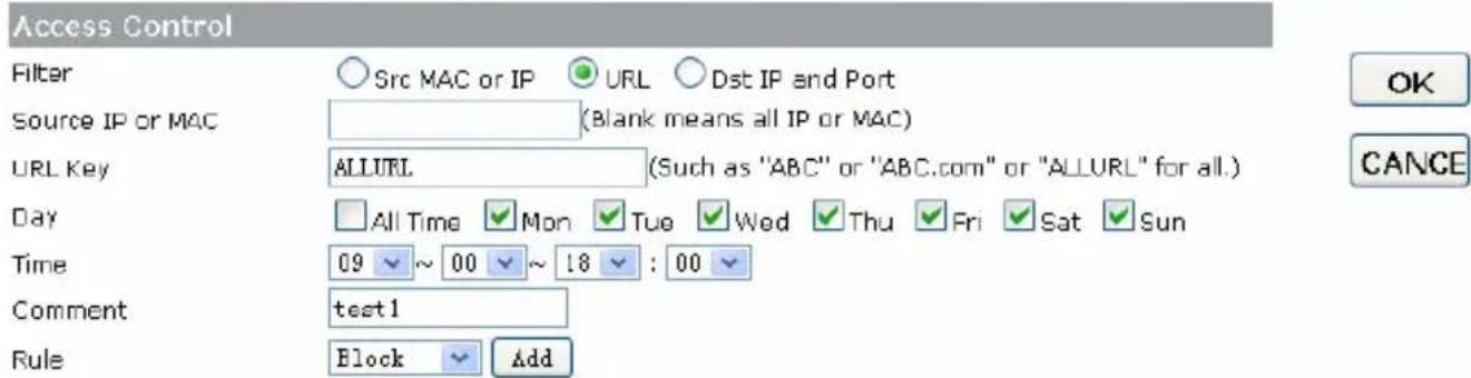
Note: Firewalls search the first match rule from up to down for a packet, and decide whether drop or allow this packet according this rule. If you set time, you have to enable NTP client.
| Src Host | Dst Host | Week time | Status | Comt | Opt |
| All src hosts | abc | Mon,Tue,Wed,Thu,Fri,Sat,Sun,09:00,18:00 | ACCEPT | test | Og |
| All src hosts | ALLURL | Mon,Tue,Wed,Thu,Fri,Sat,Sun,09:00,18:00 | DROP | test1 | Og |
| EditDelDelAll | |||||
4. Port filter
You can limit some or all computers to access a certain destination IP and/or port.
Example 1: block all computers to access port 21.

Example 2: block the computer with IP address 192.168.1.101 to access port 21.
Security
Access Control
DoS
Access Control
Filter
Source IP or MAC
Destination IP
Destination Protocol
Destination Port
Day
Time
Comment
Rule

Src MAC or IP

URL Ost IP and Port
192.168.1.101 (Blank means all IP or MAC)

(Blank means all IP address)


FTP (port: 21\~21)

All Time
Mon
Tue
□Wed
Thu
□Fri
Sat
Sun


test
Block


Note: Firewalls search the first match rule from up to down for a packet, and decide whether drop or allow this packet according to this rule. If you set time, you have to enable NTP client.
| Src Host | Dst Host | Week time | Status | Comt | Opt |
| 192.168.1.101 | TCPUDP,21,21 | All time | DROP | test | |
| Edit | Del | DelAll | |||
OK
CANCE
4.3.3 DoS
With settings on this page you can block the DoS attack.

4.4 QoS Setup
The QoS helps improving your network gaming performance by setting priorities for applications. By default the bandwidth control is disabled and the application priority is not specified.
In order to complete these settings, please follow the steps below.
- Enable this function.
- Enter the total speed or choose automatic mode.
- Enter the IP address of the user which you'd like to control.
- Specify how to control the PC with this IP address: Maximum or minimum bandwidth, priority and its up/download speed.
- Click Add button to add this record to the control table, click OK button to make it effective.
QoS
Bandwidth Control
Status

Enable
Total Speed(KB/s)

Down

Automatically
OK
Add Rules
Hosts

IP Address

All others
IP Address Range

2.168.1.100

100
Mode

nit the max

bandwidth

Priority
High

Speed(KB/s)

128
Down
256
Comment
test
Add
Note: By MAC&IP binding, you can control bandwidth according to MAC address;
A static route is a pre-determined pathway that the network information should travel to reach a specific host or network.
Route Setup
Routing Setting
Static Route
IP Address
Subnet Mask
Default Gateway
Routing Table

Enable

OK
CANCE
Static Route Table
| Destination IP Address | Netmask | Gateway | Select |
DELETE SELECTED
DELETE ALL
CANCEL
Static Route: Click this box to enable the static route.
IP Address: The network or host IP address wished to be accessed.
Subnet Mask: The subnet mask of the destination IP.
Default Gateway: the router or host IP address where the network packet was originally sent. It must be on the same network segment with the WAN or LAN port.
Routing Table: Clicking the Show button will let you see the whole routing table.
Static Route table: shows all the records in the static routing table. You can delete the selected record or all records at once.
4.6 System
4.6.1 Upgrade Firmware
You can upgrade the Firmware by selecting the file and pressing the button "upload".

4.6.2 Save/Load Config
Here you can backup or restore the whole system configuration.
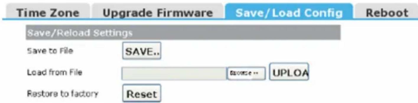
Save to File: Get the router's settings and store it on your local computer.
Load from File: Restore the settings from the file you saved before.
Restore to factory: Restore the system settings to the factory default.
4.6.3 Rebooting the device
You can reboot the device by clicking on the Reboot button.

4.6.4 Setting Password
To ensure the Router's security it is recommended to change the login and password after the first login.


natural_image
Black circular icon with a white exclamation mark in the center (no text or symbols)
natural_image
Simple line drawing of a hand washing a cup with water droplets falling (no text or symbols)

natural_image
Hand-drawn sketch of a hand using a tool to cut a screwdriver into a plastic component (no text or symbols)
natural_image
Simple line drawing of a container with a crosshair and abstract shapes, no text or symbols present.EC Declaration of Conformity
We hereby certify that the following product complies with all the relevant
Safety Requirements of § 4 EMVG and of the Directives 2006/95/EC; 93/68/EEC and 2004/108/EC.
Applicant :
Gembird Europe BV
Wittevrouwen 56,
1358CD, Almere, The Netherlands
Equipment :
Computer parts
Model Nos. :
NSW-R4
Product description :
NSW-R4 Wireless broadband router, 300M
European standards.
R&TTE ETSI 301489:2002; ETSI 30022:2000; 0 EN60950:2001;
The following manufacturer/WITHIN Europe is responsible for this declaration:
Gembird Europe BV
Wittevrouwen 56, 1358CD, Almere, The Netherlands
Tel: +31-(0)36-5211588. Fax: +31-(0)36-5347835
Director
Authorized signature
Waste disposal:

Do not deposit this equipment with the household waste. Improper disposal can harm both the environment and human health. For Information about waste collection facilities for used electrical and electronic devices, please contact your city council or an authorized company for the disposal of electrical and electronic equipment.

- Specifications
- Wireless router overview
- Front panel (LED indicators)
- Back panel (sockets description)
- Quick Installation Guide
- TCP/IP Settings
- Getting Started
- Setup Wizard
- Wizard
- Wizard Settings
- Step 1 – Operation Mode Settings
- Wizard --> Operation Mode Settings
- Gateway
- Bridge
- Wireless ISP
- Step 2 – Time Zone Settings
- Wizard --> Time Zone Settings
- Step 3 – LAN Settings
- Wizard --> LAN Settings
- Step 4 – WAN Settings
- Wizard --> WAN Settings
- Mode 2: Static IP
- Step 5 – WLAN Settings
- Wizard --> Wireless Basic Settings
- Step 6 – WLAN Security Settings
- Wizard --> Wireless Security Settings
- Encryption
- Pre-Shared Key Format
- Pre-Shared key
- Advanced Setup
- Wireless Advanced setup
- WPS
- Access Control
- WDS
- Service Setup
- Port Forwarding
- Port Forwarding
- Trigger Port
- DMZ
- UPnP
- Current Port Forwarding Table
- Trigger Port
- DMZ
- UPNP
- Security Setup
- Security
- Security
- Access Control
- DoS
- Access Control
- IP Filter
- MAC filter
- URL filter
- Port filter
- DoS
- QoS Setup
- QoS
- Bandwidth Control
- Add Rules
- Route Setup
- Routing Setting
- Static Route Table
- System
- Upgrade Firmware
- Save/Load Config
- Rebooting the device
- Setting Password
- EC Declaration of Conformity
- Waste disposal:
Brand : Gembird
Model : NSW-R4
Category : Router