MI-509B - Wall mount Mount-It! - Free user manual and instructions
Find the device manual for free MI-509B Mount-It! in PDF.


| Product Type | Wall Mount |
| Brand | Mount-It! |
| Model | MI-509B |
| Compatible Screen Size | 37-70 inches |
| VESA Compatibility | 100x100mm to 600x400mm |
| Weight Capacity | Up to 132 lbs (60 kg) |
| Material | Cold-rolled steel plate |
| Wall Plate Dimensions | 29.5 x 6.7 inches (75 x 17 cm) |
| Distance from Wall | 1.75 inches (4.45 cm) |
| Tilt Adjustment | 0 to -15 degrees |
| Level Adjustment | ±3 degrees |
| Installation | Single stud or concrete wall |
| Included Hardware | Lag bolts, concrete anchors, spacers, screws |
| Color | Black |
| Cable Management | Yes, with adjustable covers |
| Safety Certification | TUV certified |
| Maintenance | Wipe with dry cloth; check tightness periodically |
| Spare Parts Availability | Contact manufacturer |
| Warranty | Limited lifetime warranty |
Frequently Asked Questions - MI-509B Mount-It!
User questions about MI-509B Mount-It!
0 question about this device. Answer the ones you know or ask your own.
Ask a new question about this device
Download the instructions for your Wall mount in PDF format for free! Find your manual MI-509B - Mount-It! and take your electronic device back in hand. On this page are published all the documents necessary for the use of your device. MI-509B by Mount-It!.
USER MANUAL MI-509B Mount-It!
natural_image
Technical line drawing of a mechanical assembly with vertical supports and a central shaft (no text or symbols)TV CEILING MOUNT

HAVE QUESTIONS?
Monday - Friday from 8:00am - 4:00pm PST

support@mount-it.com

(855) 925-5668

www.mount-it.com
Thank you for choosing Mount-It!!
EN Read the entire instruction manual before you start installation and assembly. If you have any questions regarding any of the instructions or warnings, please contact Amount-11 for assistance.
CAUTION: Use with products heavier than the rated weights indicated may result in instability causing possible injury.
- Moutits must be attached to specified in assembly instructions. Improper installation may result in damage of serious personal injury. - Safety next and proper tools must be used. This product should only be installed by professionals.
- Make sure that the supporting surface will safely support the combined weight of the equipment and all attached hardware and components.
- Use the mounting screws provided and DO NOT OVER TIGHTEN mounting screws
• This product contains small items that could be a choking hazard if swallowed. Keep these items away from children.
- This product is intended for indoor use only. Using this product outdoors could lead to product failure and personal injury. IMPORTANT: Figure 3: you have received all name attention to the same subject cholesterol test in infants. If any study are missing or fully interested
OR OR AN: Ensure that you have received all joints according to the component of the main prior to rehabilitation, if any joints are missing or so highly appropriate. 12-24 H for a replacement
MAINTENANCE: Checks that the bracket is secure and safe in use at regular intervals (at least every three months).
PROVISION: - The function of the earth's earth's possible defect is affected. For each of the earth's initial defect cannot be considered
The following table provides the results of the 2016 and 2017 annual estimates, including estimates for the year ended December 31, 2016, and 2017. The estimates for the year ended December 31, 2016, are based on the present value of \1,000 million, which is estimated at \1,000 million and is further reported by the actual value.
The WILVERSA, HONGKU, and GAE, NY, Company, and the property, as described from the above section of the Company's 2016 Annual Report on the Interests Act of Operations, Section 4 of the above: The Level rate is a Full-Value.
natural_image
Technical line drawings of two mechanical components labeled A (x1) and B (x1), showing different assembly configurations (no text or symbols beyond labels)Ceiling Bracket
C (x2)
VESA Arms

E (×2)
Height Adjustment
Holts

F{×2}
Height Adjustment
Nuts

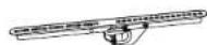
D (x1)
Horizontal Arm

G{x1}
Wrench

H(x1)
Allen Wrench
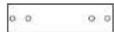
1(x)
Mounting Template
J (x2)
End Caps for Horizontal Arm

K{x1}
Connector Bracket

M5x10
L (14)
Bolt for End Caps

M5×14
M (x4)
Bolt
TV MOUNTING HARDWARE


CEILING MOUNTING HARDWARE

W-A (x6)

VH3 (x6)

WHC (x6)
Lag Screw Concrete Anchor Washer
Check carefully to make sure there are no missing or defective parts. Some hardware provided
may not be used. Use the correct wall mounting and monitor mounting hardware suitable for your installation.
CHOKING HAZARD. Package includes small parts.
Not for children under 3 years. Adult supervision is required.
Missing Parts? Call us at (855) 925-5668 and we will ship replacement parts free of charge.
Step 1a Step 1b
Mounting to a Wood Stud or Joist
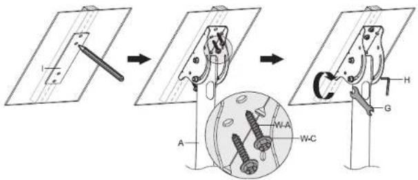
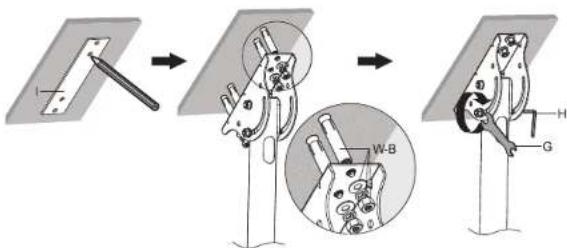
- Using a stud finder locate the center of the ceiling joist or angled wall stud. Center the Mounting Template (#1) on the stud and mark the center of the holes with a pencil.
- Drill pilot holes on the marked locations using a 3/16" drill bit to a depth of 2.2". Attach Ceiling Bracket (#A) to the drilled holes using Lag Screws (#W-A) and Washers (#W-C) and tighten until secure.
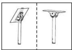
- Allow the pole to hang freely downward and then lighten the lower nut and bolt on the bracket (pictured below) by tightening the nut clockwise with Wrench (#G), holding the bolt in place on the other end with Allen Wrench (#H).
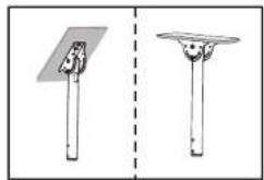
Note: In addition to normal ceiling mounting, this product may be mounted to angled ceiling surfaces or to the side of an exposed joist at a maximum of a 90° angle.

natural_image
Two simple line drawings of a solar panel with a base and a top, separated by a dashed line (no text or symbols)
Mounting to Concrete or Brick
- Place the mounting template in the desired location and mark the center of the holes with a pencil. - Drill holes on the marked locations using a 12 " drill bit to a depth of 1.8". Clear dust and debris from the hole. Insert Concrete Anchors (#W-B) into the holes and remove the nut, lock washer, and washer from the end. Place the Ceiling Bracket (#A) over the protruding ends of the anchors and replace the removed pieces in order (Washer, lock washer, then nut) and tighten the nuts until secure. - Allow the pole to hang freely downward and then tighten the lower nut and bolt on the bracket (pictured below) by tightening the nut clockwise with Wrench (#G), holding the bolt in place on the other end with Allen Wrench (#H).
Note: Do not drill mounting holes into mortar (such as between bricks or stones) only drill and install into solid stone or concrete surfaces.

natural_image
Two simple line drawings of a support pole with a flat base and a circular base, separated by a dashed vertical line (no text or symbols)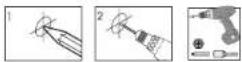
Step 2 Routing Cables and Installing the Lower Pole
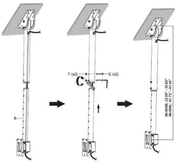
- Route the TV cables as shown through the upper and lower poles. Insert the lower pole inside the upper portion and position at the desired height. Secure the pole in place using Height Adjustment Bolts (#E) and Nuts (#F).
Step 3 Assembling the Horizontal Arm
- Insert Horizontal Arm (#D) through the openings in Connector Bracket (#K) and center it on the arm. Secure the two components together with Bolts M as shown. - Attach End Caps (#J) to the ends of Horizontal Arm (#D) and secure them with Bolts (#L).
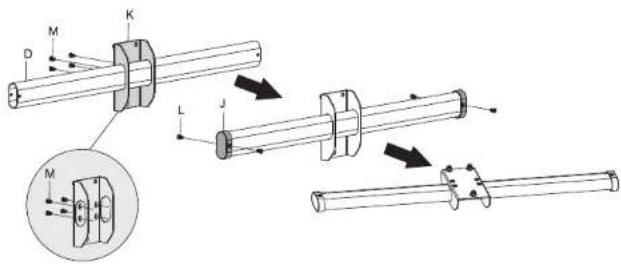
Step 4 Attaching the Horizontal Arm to the Mount
- Remove the single lower nut (pictured in the magnification bubble below) on the rear of the now assembled horizontal arm. Hang the top two nuts onto the corresponding slots on the end of the Lower Pole (#B) and the now exposed bolt will pass through the single corresponding hole. Reattach the nut and tighten until secure.
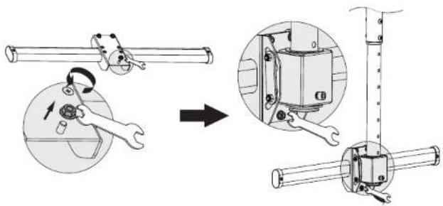
Step 5
Removing the Security Screw
- Remove the security screw pictured below from each of the VESA Arms (#C).

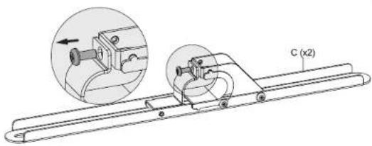
natural_image
Technical line drawing of a mechanical assembly with a magnified inset showing a component detail (no text or symbols)Step 6a
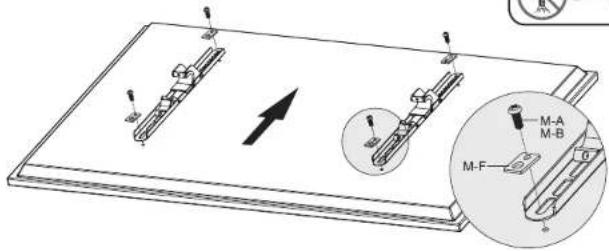
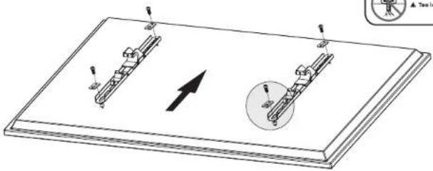
Attaching the VESA Arms to the TV (No Spacers)
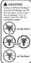
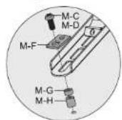
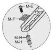
- Spacers will not be required if the VESA bolts used are the correct length that matches the depth of the TV VESA holes. - Select the appropriate size mounting bolt (M-M-A though M-E) for your display's mounting holes and verify the length of the VESA bolt is not too long. If you are unsure of the correct bolt size for your display refer to your TV user manual or contact the TV manufacturer for sizing information. Square Washer (M-M-F) must be used in all configurations.

MOUNT-IT!
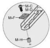
Step 6b
Attaching the VESA Arms to the TV (With Spacers)
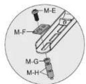
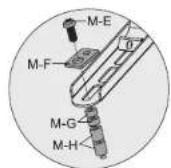
- Spacers will be required if the VESA bolts used are too long for the depth of the TV VESA holes. Spacers are provided to adjust the length of the mounting bolt. - Select the appropriate size mounting bolt (#M-A though M-E) for your display's mounting holes and verify the length of the VESA bolt is not too long. If you are unsure of the correct bolt size for your display refer to your TV user manual or contact the TV manufacturer for sizing information. If necessary, use the included spacers (#M-G, M-H) between the mount and the TV as shown below to adjust the length of the mounting bolt. Multiple spacers can be used in combination to achieve the desired bolt depth. Square Washer (#M-F) must be used in all configurations.
natural_image
Technical diagram of a mechanical assembly with two components and an arrow indicating direction (no text or symbols)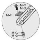
MOUNT-IT!
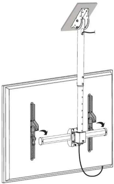
Step 7 Hanging the TV onto the Horizontal Arm
- Hang the TV on the horizontal arm as shown so that the full weight of the screen is being supported by the VESA arms. Note: It is recommended that at least two persons assist during this step.

HEAVY! You may need assistance with this step.
natural_image
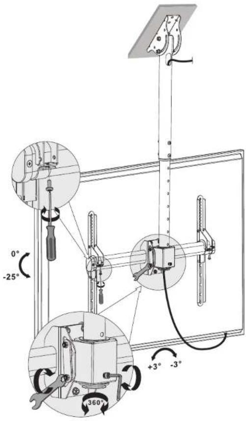
Technical line drawing of a mechanical assembly with rotating components and a top-mounted bracket (no text or symbols)Step 8 Final Adjustments
- Re-insert the security bolts (removed in step 5) so that the TV cannot be accidentally removed from the mount.

Visit us at www.mount-it.com for product registration and warranty information.
Our US based customer service team is standing by to answer any questions you have about your Mount-It! product.
Available by phone Monday - Friday from 8:00am to 4:00pm PST.
Chat live with an agent on our website!

support@mount-it.com

(855) 925-5668

www.mount-it.com
- TV CEILING MOUNT
- HAVE QUESTIONS?
- Thank you for choosing Mount-It!!
- Step 1a Step 1b
- Mounting to a Wood Stud or Joist
- Mounting to Concrete or Brick
- Step 2 Routing Cables and Installing the Lower Pole
- Step 3 Assembling the Horizontal Arm
- Step 4 Attaching the Horizontal Arm to the Mount
- Step 5
- Removing the Security Screw
- Step 6a
- Attaching the VESA Arms to the TV (No Spacers)
- Step 6b
- Attaching the VESA Arms to the TV (With Spacers)
- Step 7 Hanging the TV onto the Horizontal Arm
- Step 8 Final Adjustments
Brand : Mount-It!
Model : MI-509B
Category : Wall mount