KSTAW12CE - Air conditioner Keystone - Free user manual and instructions
Find the device manual for free KSTAW12CE Keystone in PDF.


| Product Type | Window Air Conditioner |
| Model | KSTAW12CE |
| Brand | Keystone |
| Cooling Capacity (BTU/h) | 12,000 |
| Appropriate Room Size | Up to 550 sq ft (est.) |
| Window Opening Width | 23 to 36 inches (584-914 mm) |
| Window Opening Minimum Height | 13 inches (330 mm) |
| Unit Height | 15-1/2 inches (394 mm) |
| Power Supply | 115V / 60Hz (est.) |
| Power Cord | 3-prong grounded plug |
| Installation | Standard double hung window |
| Air Direction Control | Adjustable louvers |
| Filter | Washable foam filter |
| Condensate Drainage | Rear drain holes, tilted back for proper drainage |
| Weight (approx.) | 70 lbs (32 kg) |
| Safety Features | Ground prong, sash lock, frame lock |
| Required Tools | Screwdriver, level, ruler, scissors |
| Included Accessories | Top rail, accordion panels, frame lock, sash lock, weather stripping, screws |
| Energy Star Model | Yes (includes R1 hardware and weather stripping) |
Frequently Asked Questions - KSTAW12CE Keystone
User questions about KSTAW12CE Keystone
0 question about this device. Answer the ones you know or ask your own.
Ask a new question about this device
Download the instructions for your Air conditioner in PDF format for free! Find your manual KSTAW12CE - Keystone and take your electronic device back in hand. On this page are published all the documents necessary for the use of your device. KSTAW12CE by Keystone.
USER MANUAL KSTAW12CE Keystone
Read these instructions completely and carefully.
IMPORTANT- Save these instructions for local inspector s use.
IMPORTANT- Observe all governing codes and ordianaces.
Note to Installer- Be sure to leave instructions with the Consumer.
Note to Consumer- Keep these instructions for futrue reference.
Skill level- Installatio of this appliance requires basic mechanical skills.
Completion time- Approximately 1 hour
We recommend that two people install this product.
Proper installation is the responsibility of the installer.
Product failure due to improper installation is not covered under the Warranty.
You MUST use all supplied parts and use proper installation procedures as described in these instructions when installing this conditioner.

WINDOW REQUIREMENTS
Your air conditioner is designed to install in standard double hung windows with opening widths of 23 to 36 inches(584mm to 914mm)
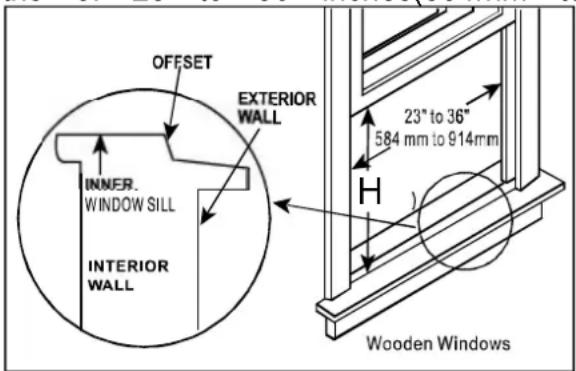
| Model H | 6000~8000Btu/h | 10000~12000Btu/h |
| 14"(356mm) | 15-1/2"(394mm) |
Table 1

CAUTION
Do not, under any circumstances, cut or remove the third (ground) prong from the power cord.
Do not change the plug on the power co of the air conditioner.
Aluminum house wiring may present special problems-consult a qualified electrician. these
When handling unit, be careful to avoid cuts sharp metal edges and aluminum fins on front rear coils.
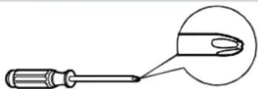
TOOLS YOU WILL NEED
natural_image
Diagram of a screwdriver with a magnified view of the tip (no text or symbols)Screwdriver

Level
TOOLS YOU MAY USE

Screwdriver
Pencil
Ruler or tape measure
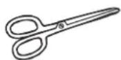
Scissors or knife

NOTE:
Save Carton and these Installation Instruction for future reference. The carton is the best to store unit during winter, or when not in

PREPARE THE WINDOW
Lower sash must open sufficiently to allow a clear vertical opening of 13 inches (330mm). Side louvers and the rear of the AC must have clear air space to allow enough airflow through the condenser, for heat removal. The rear of the unit must be outdoors, not inside a building or garage.
Mounting Hardware


3/4"(or 1/2)" Screws
(7)
Lock Frame
(2)
Sash Lock
(1)
Window sash Weather seal foam stripping
(1)
(10 ^ 3/4 ^ 1/12 ^* )
(5)
NOET: Weather stripping is only for Energy star models.

PREPARE AIR CONDITIONER
A: Remove the air conditioner from the carton and place on a flat surface.
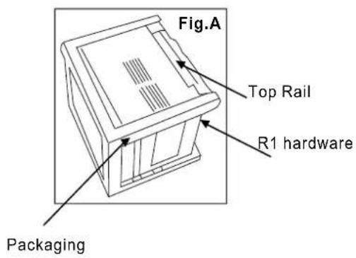
B: Remove top rail and R1 hardware (R1 hardware only for Energy star models) from the rear of the packaging material as shown in Fig. A.
Top Rail and R1 Hardware
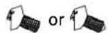
3/8 Screws
(4)
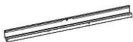
Top Rail
(1)
R1 hardware
(2)
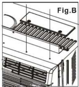
C: Align the hole in the top rail with those in the top of the unit as shown in Fig.B
natural_image
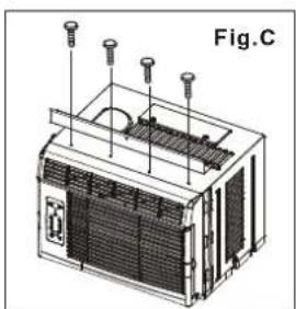
Technical diagram of a roof drainage system with ventilation grilles and ventilation ducts (no text or labels)D: Secure the top rail to the unit with the 3/8 Screws as shown in Fig.C.
natural_image
Technical line drawing of a mechanical device with mounting holes and internal components (no text or symbols)NOTE: For safety reasons, all four(4) screws MUST be securely fastened.

INSTALL THE ACCORDION PANELS
NOTE: Top rail and Sliding Panels at each side are offset to provide the proper pitch to the rear of (5/16). This is necessary for proper condensed water utilization and drainage. If you are not using the Side Panels for any reason, this pitch to the rear must be maintained.
natural_image
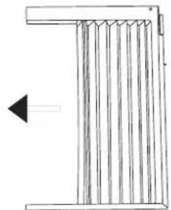
Pure technical diagram of a vertical structural component with internal parallel elements, no text or symbols presentA. Place unit on floor, a bench or a table. Hold the Accordion Panel in one hand and gently pull back the center to free the open end. See Fig.1
Fig.1
B. Slide the free ehd " " section of the panel into the cabinet as shown in Fig. 2. Slide the down. Be sure to leave enough space to slip top and bottom of the frame into the rails on cabinet.
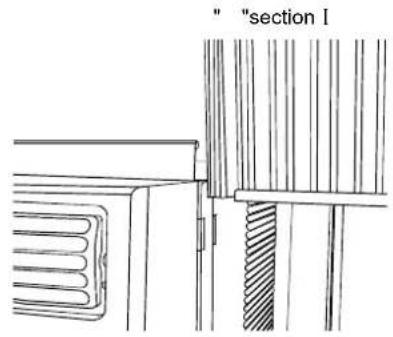
Fig.2
C. Once the panel has been installed on the cabinet, make sure it sits securely inside frame channel by making slight adjustments. Slide the top and bottom ends of the frame top and bottom rails of the cabinet. Fig.3.
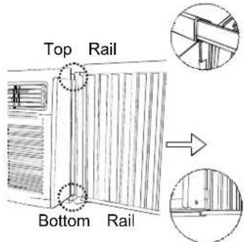
Fig.3
D. Slide the panel all the way in and repeat other side.
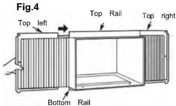
NOTE: If storm window blocks AC, see Fig. 11.

SECURE THE ACCORDION PANE LS
The Keep a firm grip on the air conditioner, carefully place the unit into the window opening so the bottle of the air conditioner frame is against the window sill (Fig.5). Carefully close the window behind the to rail of the unit.
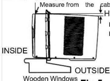
H: About 3/4" to 1" (for 5 to 8K); H: About 1" to 1³/l₈" (for 10 to 12K);
Fig.5
NOTE: Check that air conditioner is tilted back above H (Fig.5)(tilted about ^ 3 to 4 downward to the outside proper installation, condensate should not drain from the overflow drain hole during normal use, correct the slope otherwise.
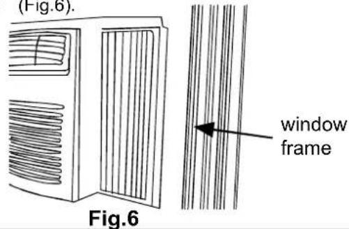
B. Extend the side panels out against the window frame (Fig.6).

INSTALL SUPPORT BRACKET
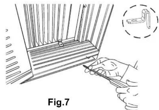
on AtTrace the frame lock between the frame extensions and the window sill as shown(Fig.7). Drive 3 /" 4 (19mm) of 2"(12.7mm) locking screws through the frame lock and into the sill .
NOTE: To prevent window sill from splitting, drill 1 / 8" (3mm) pilot holes before driving screws.
natural_image
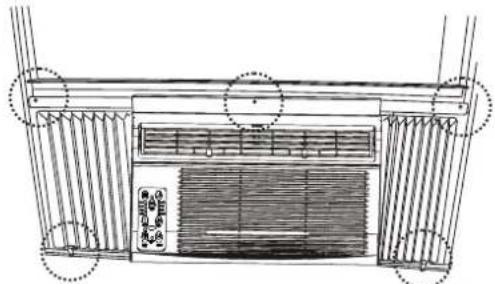
Line drawing of a hand holding a tool near a window frame, with an inset showing a small mechanical component (no text or symbols)B. Drive 31/42" ((192m7m)m) locking screws through frame holes into window sash (Fig.8).
natural_image
Line drawing of a front view of an air conditioner unit with cooling fins and ventilation grilles (no text or symbols)Fig.8
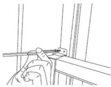
C. To secure lower sash in place, attach right angle sash lock with 3/4" (19mm) or 125 (new7asm) shown(Fig.9).
natural_image
Line drawing of a hand holding a tool near a vertical structure (no text or symbols)Fig.9
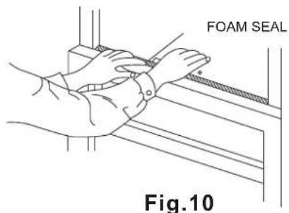
D. Cut Windows ash shell foam space between the upper and lower sashes (Fig.10).

INSTALL R1 HARDWARE (only be applicable to Energy star models)
In order to minimize air leaks and ensure optimal insulation, it is necessary to install the included R1 hardware to the side curtain. Follow the instructions below.
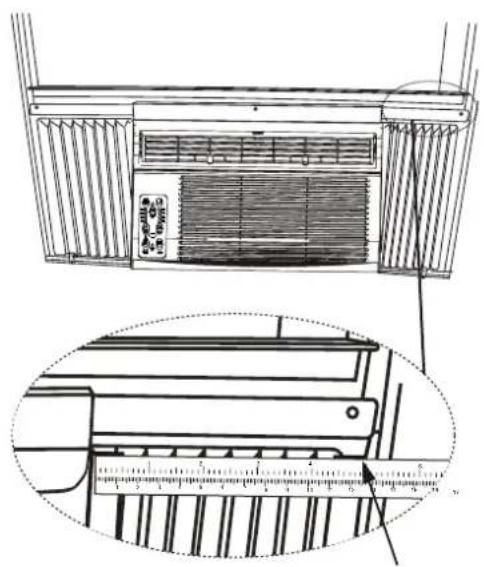
Step 1. After the unit is installed to the window, measure the inner width of the side curtain as shown (Fig.11).
Step 2. Remark a line on the provide R1 insulation panel according to a length 1/8 (3mm) less than the measured width in step 1, then cut the R1 insulation panel along the line (Fig.12).
natural_image
Technical line drawing of an air conditioner unit with internal panel and side view showing measurement scale (no text or symbols)Measure the inner width of the side curtain
Fig.11
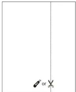
Fig.12
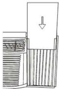
Step 3. Slide the R1 insulation panel into the side curtain, the side with pattern should facing the indoor side.(Fig.13).
natural_image
Diagram of a mechanical device with a downward arrow indicating force or direction (no text or symbols present)Fig.13
Step 4. Repeat on the other side.
7 INSTALL WEATHER STRIPPING (only be applicable to Energy star models)
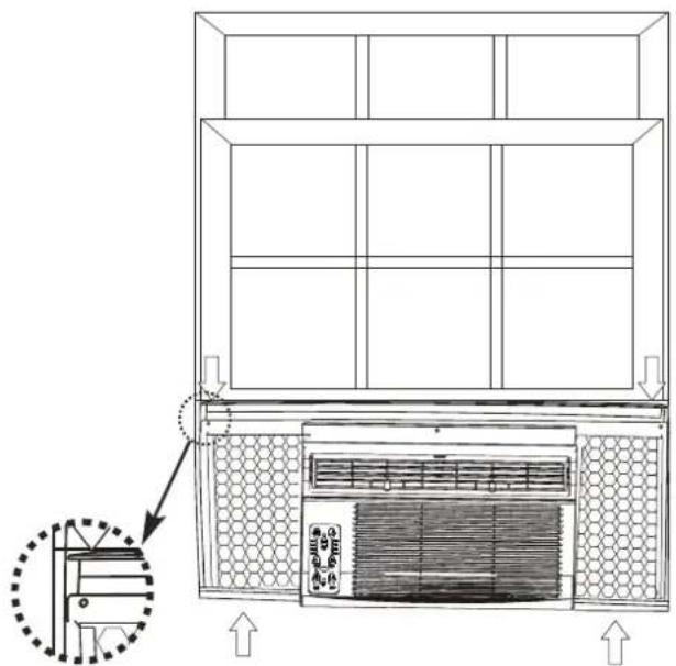
In order to minimize air leaks between the room air conditioner and the window opening, trim the weather sttipping with a proper length, peel off the protective backing and plug any gaps if needed (Fig.14).
natural_image
Technical line drawing of a cabinet or air conditioner unit with ventilation grilles and a highlighted internal component (no text or symbols)Fig.14
If AC is Blocked by Storm Window
Add wood as shown in Fig.15, or remove storm window before air conditioner is installed.
If Storm Window Frame must remain, be sure the drain holes or slots are not caulked or painted shut. Accumulated Rain Water or Condensation must be allowed to drain out.
Removing AC From Window
Turn AC off, and disconnect power cord.
Remove sash seal from between windows, and unscrew safety sash lock.
Remove screws installed through frame and frame-lock.
Remove the R1 Panel and close (slide) side panels into frame.
Keeping a firm grip on air conditioner, raise sash and carefully remove.
Be carefully not to spill any remaining water while lifting unit from window. Store parts WITH air conditioner.
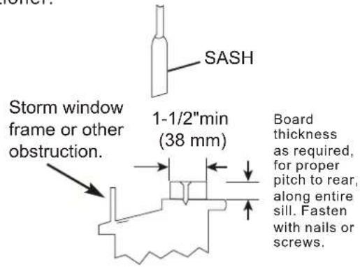
Fig.15
- WINDOW REQUIREMENTS
- CAUTION
- NOTE:
- PREPARE THE WINDOW
- PREPARE AIR CONDITIONER
- INSTALL THE ACCORDION PANELS
- SECURE THE ACCORDION PANE LS
- INSTALL SUPPORT BRACKET
- INSTALL R1 HARDWARE (only be applicable to Energy star models)
- INSTALL WEATHER STRIPPING (only be applicable to Energy star models)
- If AC is Blocked by Storm Window
- Removing AC From Window
Brand : Keystone
Model : KSTAW12CE
Category : Air conditioner