
MS-2A - Measurement Megger - Free user manual and instructions
Find the device manual for free MS-2A Megger in PDF.


| Product Type | Insulation and Continuity Tester |
| Brand | Megger |
| Model | MS-2A |
| Measurement Functions | Insulation Resistance (250V, 500V, 1000V), Continuity, AC/DC Voltage up to 600V |
| Insulation Resistance Range | 0.01 MΩ to 2000 MΩ |
| Continuity Range | 0.01 Ω to 100 Ω |
| Voltage Measurement | AC/DC 0 to 600V |
| Display | Analog scale with mirror scale for precision |
| Power Supply | 6 x 1.5V AA batteries (LR6) |
| Battery Life | Approximately 3000 measurements of 5 seconds each |
| Dimensions (H x W x D) | 200 mm x 100 mm x 50 mm |
| Weight | 0.5 kg (including batteries) |
| Safety Rating | CAT III 600V, double insulation per IEC 61010 |
| Protection Rating | IP40 (enclosure) |
| Operating Temperature | -10°C to +55°C |
| Storage Temperature | -20°C to +70°C |
| Humidity | 0 to 90% RH (non-condensing) |
| Accessories Included | Test leads with probes, alligator clips, carrying case, batteries |
| Standards Compliance | IEC 61557, EN 61326, EN 61010 |
| Cleaning and Maintenance | Wipe with a damp cloth; do not use solvents |
| Spare Parts Availability | Test leads, batteries, fuses (if applicable) |
| Reparability | Serviceable by qualified personnel; refer to manual |
Frequently Asked Questions - MS-2A Megger
User questions about MS-2A Megger
0 question about this device. Answer the ones you know or ask your own.
Ask a new question about this device
Download the instructions for your Measurement in PDF format for free! Find your manual MS-2A - Megger and take your electronic device back in hand. On this page are published all the documents necessary for the use of your device. MS-2A by Megger.
USER MANUAL MS-2A Megger
HIGH CURRENT TEST SET
MODEL MS-2A
It is essential that this instruction book be read thoroughly before putting the equipment in service.
APPRECIATION
We are indebted to the manufacturers of circuit breakers and motor overload relays, who have given their time and advice in the preparation of this instruction book.
IMPORTANT
The information and data contained within this instruction manual are proprietary with MEGGER. The equipment described herein may be protected by one or more U.S. letters patent. MEGGER specifically reserves to itself all rights to such proprietary information as well as all rights under any such patent, none of which is waived by the submission of this instruction manual to anyone.
The recipient, if a Government agency, acknowledges that this instruction book and the equipment described were procured with "Limited Rights" to technical data as described in ASPR 9-203 (b).
Copyright MEGGER, 1983, 1984, 1985, 1986, 1987, 1988, 1991, 1992, 2008
TABLE OF CONTENTS
SECTION PAGE
INTRODUCTION
GENERAL DESCRIPTION......Bulletin
SPECIFICATIONS......Bulletin
SAFETY PRECAUTIONS.... 1
THEORY OF OPERATION.... 2
DESCRIPTION OF CONTROLS 2
SELECTION OF OUTPUT TERMINAL 5
OVERLOAD CAPACITY.... 7
STORAGE AND OPERATION CONDITIONS 8
TEST PROCEDURE 9
TIME DELAY OF MOTOR OVERLOAD RELAYS 9
INSTANTANEOUS ELEMENT OF MOTOR OVERLOAD RELAYS.... 11
THERMAL ELEMENT OF MOLDED CASE CIRCUIT BREAKERS 13
INSTANTANEOUS ELEMENT OF MOLDED CASE CIRCUIT BREAKERS ..... 15
CIRCUIT BREAKER GROUND FAULT TRIP DEVICES 17
OVERLOAD DEVICES MAINTENANCE DATA 19
MAINTENANCE OF MOLDED CASE CIRCUIT BREAKERS.... 19
MAINTENANCE OF MOTOR OVERLOAD RELAYS 20
Every consideration has been given to the design and construction of the Megger Model MS-2A Portable High Current Test Set to make it a safe piece of test equipment as well as one that is accurate, reliable, and easy to use.
WARNING
The Model MS-2A is not designed for use on energized circuits. For the safety of the operator and protection of the instrument, do not connect it to circuits that are energized. This includes circuits that could become energized during the course of a test procedure utilizing this instrument.
It must be remembered that the test set is capable of producing voltage and current levels that can be deadly if personnel come in contact with them.
For safe operation, it is absolutely essential that the technician properly and effectively ground (earth) the test set. This is accomplished by connecting the input line cord to a properly grounded receptacle.
CAUTION
The input voltage of this instrument is not selectable. All the units are shipped from the factory set up for operation from either a nominal 115 volt or 230 volt source. If the unit is to be used on a voltage source different than the nameplate specifies, major changes in the test set are required. It is necessary for the technician to contact the factory to obtain the necessary parts and instructions before attempting to change the input voltage of the test set.
The MS-2A should be properly operated by qualified personnel who have familiarized themselves with the test set and thoroughly read the instruction manual provided with it.
If questions arise concerning the care, operation, maintenance or application of the test set, contact the Megger for assistance.
SYBMOLS
| 1 | IEC60417-5032 | Alternating | Current | |
| 2 |  | IEC60417-5017 Earth (ground) | Terminal | |
| 3 |  | IEC60417-5019 Protective Conductor Terminal | ||
| 4 | 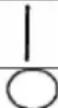 | IEC60417-5007 | On | (Supply) |
| 5 | IEC60417-5008 | Off | (Supply) | |
| 6 |  | CAUTION, Risk of danger (see Note) | ||
DESCRIPTION OF CONTROLS
This section of the instruction manual describes the functions of all the various control switches, etc. which are located on the control panel of the Model MS-2A. All controls are clearly marked and logically grouped so that continual reference to the instruction manual should not be necessary after the operator has become acquainted with operation of the test set. For the location of the controls described in this section, see MS-2A Control Panel Figure #1.
POWER ON/OFF
Switch:
Controls input power to the test set. The self-protected switch
resets after an overload, when placed in the OFF position.
Displays will light when the switch is ON.
Protects power output circuit of MS-2 against overloads.
CONTROL FUSE: Protects instrumentation and control circuitry against overloads.
OUTPUT
CONTROL:
Variable autotransformer provides continuous non-stepped output from a variety of current-rated terminals. Output system is controlled by a combination of timer STOP MODE and output mode switch positions.
OUTPUT ON Lamp: Lights whenever output control circuit is energized.
OUTPUT Terminals: A combination of the COMMON terminal and any one of the four current-designated terminals provides an output circuit. Refer to other sections of the text for an explanation of the output characteristics of these terminals.

NOTE:
The current designation of these terminals has no bearing on the actual current output capability of each. Much higher currents can be achieved depending on test circuit impedance and duration of the test.
Output Mode Switch: Initiates the output circuit in conjunction with the appropriate Timer STOP MODE Switch position.
MOMENTARY Position:
Momentary 'ON' position with spring return to 'OFF'. Output will remain energized as long as switch is held in MOMENTARY position and is de-energized when released. Timer starts and stops in the same manner. Used for 'jogging' the output circuit.
MAINTAIN
Position:
Maintained 'ON' position with spring return to 'OFF'. Output will remain energized until appropriate STOP MODE function occurs, switch is moved to 'OFF' position or current drops below threshold requirement.
OFF Position:
Test set input power remains energized but output current remains de-energized and timer will not count.
AMMETER: LED displays show the numeral one in the left most position when the meter is over-ranged.
RANGE SWITCH: Decimal of display shifts one digit to the right for each increase in range selection.
DISPLAY MODE Switch:
Selects either the NORMAL or MEMORY mode of the ammeter.
NORMAL Position:
Ammeter updates reading continually as long as the output is energized. Reading is lost when the output is de-energized.
MEMORY Position:
Ammeter retains the highest peak value attained during current output operation above 8% of the full scale when using the lowest three ranges. When in the highest ammeter range (750 amp), the ammeter will retain the peak value attained during current output operation above 160 amps. Reading is retained until the output is re-initiated or RANGE SWITCH position is changed.
TIMER: Automatically resets each time output is re-initiated.
CYCLES/SEC. Switch:
Selects cycles or seconds mode.
CYCLES Position:
The timer counts in whole cycles and uses the power input line frequency as timing reference.
SEC. Position:
The timer counts in two selectable increments and uses an internal 10kHz oscillator as timing reference.
.01/.001 Switch: Selects one of two counting increments available for the timer
SEC. mode.

Note: Changing the position of the CYCLE/SEC. Switch (or the .01/.001 Switch while in the SEC. position) during timer operation will produce erroneous readings.
CONTACTS Binding Posts:
Circuit controls output and timer in the normally open or normally closed positions of the STOP MODE Switch.

Note: Do not connect CONTACTS binding posts to an energized circuit.
STOP MODE Switch: Selects either current actuated position to stop the current output and timer, or either of the two external contact stop mode positions.
NORM. OPEN Position:
With CONTACTS binding posts connected to normally open contacts, output circuit will remain energized and timer will continue to run until contacts close.
NORM. CLOSED Position:
With CONTACTS binding posts connected to normally closed external contacts, output circuit will remain energized and timer will continue to run until contacts open.
CURRENT Position:
Timer will initiate only when the output circuit is completed and a minimum threshold current is exceeded. The minimum threshold for the lower three ranges is approximately 8 % of full scale, whereas the minimum threshold for the highest (750 amp) range will be approximately 160 amps. Timer will continue to run until output circuit opens, current drops below threshold level, or output is de-energized.
SELECTION OF OUTPUT TERMINAL
Four output terminals at various voltage and current ratings are provided to adapt the MS-2A to a wide variety of test circuit impedances.
The current ratings shown on the output taps are the continuous duty ratings. The test set works at peak efficiency when the outputs are used at two to three times their continuous rating. In this way, finer adjustment can be obtained by making full use of the variable autotransformer range. The LOW CURRENT-HIGH VOLTAGE terminals should be used when testing high impedance devices where the lower voltage terminal(s) will not "push" the desired test current through the device. For example, to test a breaker rated at 15 amperes, at a test multiple of 3X (45 amperes), the operator should use the 25A output tap (not the 120A tap).
IT SHOULD BE NOTED THAT THERE IS NO RELATIONSHIP BETWEEN THE AMMETER RANGES AND THE RATING OF THE OUTPUT TERMINAL. All ammeter ranges can be used in conjunction with any of the output terminals.

MS-2A Control Panel
Figure 1
OVERLOAD CAPACITY
Model MS-2A is rated at 0.6 KVA output and is equipped with four output terminals, each capable of supplying its rated current. The current rating of these output terminals may be exceeded for short durations provided the voltage rating is sufficient to "push" the desired current through the device under test and the connecting test leads. The overload capacity, represented by multiples of rated current, versus TIME ON and TIME OFF are given below:
| % RatedCurrent | MaximumTime ON | MinimumTime OFF | |||
| 100 | (1X) | 30 | minutes | 30 | minutes |
| 150 (1.5X) | 6 minutes | 13 minutes | |||
| 200 (2X) | 3 minutes | 8 minutes | |||
| 250 (2.5X) | 1 minute | 6 minutes | |||
| 300 (3X) | 30 seconds | 4 minutes | |||
| 400 (4X) | 7 seconds | 2 minutes | |||
Model MS-2A also can be used continuously for any reasonable length of time at 70.7% of the current rating of the output terminal.
EXAMPLE:
Consider the terminal rated at 240 amperes:
(a) 240 amperes may be drawn at any voltage from 0-2.5 volts for 30 minutes provided the test set is subsequently de-energized for 30 minutes.
(b) 169.7 amperes (70.7% of 240 amperes) may be continuously drawn at any voltage from 0-2.5 volts for any reasonable length of time.
(c) The following overload currents may be drawn at any voltage from zero to maximum volts for the Time ON indicated, followed by the indicated Time OFF. The maximum output voltage available when the current rating of the output terminal is exceeded (overloaded) will be less than the rated value due to the regulation of the transformer in the test set. For example, when drawing 360 amperes from the 240 ampere terminal, the maximum voltage available is approximately 2.0 volts.
| Overload From 240 Ampere | Current | ||||
| Terminal | Time ON | Time OFF | |||
| 360 | amperes | 6 | minutes | 13 | minutes |
| 480 | amperes | 3 | minutes | 8 minutes | |
It should be noted that because of the impedance of the device under test and the connecting test leads, the maximum practical test current available from the terminal rated 240 amperes is approximately 360 amperes. Higher currents are usually available from the terminal rated 120 amperes; HOWEVER, these higher currents are available only for very short durations as illustrated in the overload capacity table above. For example, it is possible to get 480 amperes from this terminal for seven (7) seconds, followed by two (2) minutes off.
STORAGE AND OPERATION CONDITIONS
The unit is housed in an industrial grade plastic enclosure. There are no special storage requirements in the area of ventilation, or preservation with the lid securely attached to the unit. The unit is designed to be operational at temperatures between 0^ C to 50^ C and relative humidity between 0% and 90% non-condensing. The unit can be stored at temperatures between -25^ C to 70^ C and relative humidity between 0% and 90% non-condensing.
TEST PROCEDURE FOR TIME DELAY OF MOTOR OVERLOAD RELAYS
- Set-up MS-2A with:
a. POWER ON/OFF Switch in OFF position (instrument displays off).
b. OUTPUT CONTROL knob at minimum '0' position.
c. Output Mode Switch (Maintain/Off/Momentary) to the center OFF position.
- Connect one end of a high-current lead to one side of thermal element or current coil in overload relay. Connect other end of this lead to the COMMON terminal of test set.
- Connect one end of second high-current lead to other side of thermal element or current coil in overload relay. Connect other end of this lead to the appropriate output terminal (see SELECTION OF OUTPUT TERMINAL, page 5).
- Connect test set to suitable single-phase power supply.
- Turn test set on with POWER ON/OFF Switch (instrument displays should light).
- Use RANGE Switch to select ammeter range so test current will be near full scale and no less than 10% of full scale for the lower three ranges. For test currents exceeding 200 amps, it is recommended that the 750 amp range be selected.
- Put ammeter DISPLAY MODE Switch in MEMORY position.
- Connect a pair of leads (timer leads) from Normally Closed Contacts or Normally Open Contacts of overload relay to binding posts of test set labeled CONTACTS.
- Select appropriate Timer STOP MODE.
- Select desired Timer Display Mode and Range.
- Rotate OUTPUT CONTROL knob clockwise and momentarily press Output Mode Switch in MOMENTARY and release. Observe current reading retained by ammeter.
- Continue to rotate OUTPUT CONTROL knob clockwise while jogging Output Mode Switch (repeatedly moving to MOMENTARY position and releasing) until desired test current is reached. Suggested test current is three times (3X) the rating of thermal relays or three times (3X) the pick-up current of magnetic relays.
If the relay utilizes a high impedance thermal element or operating coil and the desired test current cannot be reached, transfer output lead to the next higher voltage (lower current) terminal, and repeat Steps 11 and 12. If test current is still not reached, transfer output lead to the terminal labeled 5A, and repeat Steps 11 and 12 (see SELECTION OF OUTPUT TERMINAL, page 5).

NOTE: Before starting test, allow time for thermal element to cool; or in the case of magnetic overload relays, for the piston to reset. Incorrect tripping time may otherwise result.
-
Put ammeter DISPLAY MODE in NORMAL position.
-
Start test by moving Output Mode Switch to MAINTAIN position.

NOTE: Test current may decrease (fall off) during the test because the resistance or impedance of the test circuit increases as it heats up. Rotate OUTPUT CONTROL knob clockwise to keep test current at desired value.
-
When overload relay trips, timer stops and output is de-energized. Timer indicates total elapsed time of the test in Seconds or Cycles.
-
Turn test set OFF with POWER ON/OFF Switch.
-
Record test results on Test Record Card.

IMPORTANT NOTE
In order to obtain accurate tripping times with some types of magnetic overload relays, particularly those relays using high viscosity oil, it may be necessary to "preheat" the relay by running rated current through the relay for a few minutes.
TEST PROCEDURE FOR
INSTANTANEOUS ELEMENT OF MOTOR OVERLOAD RELAYS
- Set-up MS-2A with:
a. POWER ON/OFF Switch in OFF position.
b. OUTPUT CONTROL knob at minimum, '0' position.
c. Output Mode Switch in center OFF position.
-
Connect one end of a high-current lead to one side of instantaneous element in overload relay. Connect other end of this lead to the COMMON terminal of test set.
-
Connect one end of second high-current lead to other side of instantaneous element in overload relay. Connect other end to the appropriate output terminal (see SELECTION OF OUTPUT TERMINAL, page 5).
-
Connect test set to suitable single-phase power supply.
-
Turn test set on with POWER ON/OFF Switch (instrument displays should light).
-
Use RANGE Switch to select ammeter range so test current will be near full scale and no less than 10% of full scale for the lower three ranges. For test currents exceeding 200 amps, it is recommended that the 750 amp range be selected.
-
Put ammeter DISPLAY MODE in MEMORY position.
-
Connect a pair of leads (timer leads) from Normally Closed Contacts or Normally Open Contacts of overload relay to binding posts of test set labeled CONTACTS.
-
Select appropriate timer STOP MODE.
-
Select desired timer display mode and range.
-
Rotate OUTPUT CONTROL knob clockwise and momentarily press Output Mode Switch in MOMENTARY and release. Observe current reading retained by ammeter.
If desired test current is not reached with OUTPUT CONTROL knob at maximum clockwise rotation, return knob to zero and transfer output lead to the next higher voltage/lower current tap. For example, from terminal labeled 240A to terminal labeled 120A. Proceed with current adjustment as in Step 11.
If the relay utilizes a high impedance instantaneous element and the desired test current cannot be reached, transfer output lead to the next higher voltage, lower current terminal, and repeat Step 11. If test current is still not reached, transfer output lead to terminal labeled 5A, and repeat Step 11 (see SELECTION OF OUTPUT TERMINAL, page 5).
- Continue Step 11 until overload relay trips. Observe current reading retained on ammeter. Timer indicates elapsed time of test in cycles or seconds.

NOTE: To avoid tripping error caused by interference of time delay element, allow thermal element to cool; or in the case of magnetic overload relays, for the piston to reset.
- Repeat test, starting with OUTPUT CONTROL knob at position just below trip current of instantaneous element observed in Step 12.
- When overload relay trips, timer stops and output is de-energized. Current reading is retained on ammeter. Timer indicates elapsed time in seconds or cycles.
- Turn test set OFF with POWER ON/OFF Switch.
- Record results on Test Record Card.

IMPORTANT NOTE
Refer to manufacturer's instructions for instantaneous trip time. If increasing test current does not decrease tripping time, current at which minimum tripping time was first observed is the instantaneous trip current value. Additionally, the test method outlined above is sometimes referred to as the "jogging" or "step" method. For nearly all applications, this method works best; however, there is another method referred to as the "run-up" method. Instead of the Output Mode Switch being in the MOMENTARY position, it is placed in the MAINTAIN position and the ammeter is placed in the NORMAL position. When the output is initiated, rotate OUTPUT CONTROL knob clockwise and observe current reading on ammeter. When the device trips, record trip current. If this method is used, it should be noted that the device is being heated with continuous current, and it is hard on the variable autotransformer windings and brush(es) (can cause premature wear-down of the brush(es) and carbon buildup - see Servicing on page 18).
TEST PROCEDURE FOR
THERMAL ELEMENT OF MOLDED CASE CIRCUIT BREAKERS
- Set-up MS-2A with:
a. POWER ON/OFF Switch in OFF position (instrument displays OFF).
b. OUTPUT CONTROL knob at minimum, '0' position.
c. Output Mode Switch in center OFF position.
- Connect one end of a high-current lead to one pole of circuit breaker. Connect the other end of this lead to the COMMON terminal of test set.
- Connect one end of the second high-current lead to the other side of the same pole of the circuit breaker. Connect other end of this lead to the appropriate output terminal (see SELECTION OF OUTPUT TERMINAL, page 5).
- Connect test set to suitable single-phase power supply.
- Turn test set on with POWER ON/OFF Switch (instrument displays should light).
- Use RANGE Switch to select ammeter range so test current will be near full scale and no less than 10% of full scale for the lower three ranges. For test currents exceeding 200 amps, it is recommended that the 750 amp range be selected.
- Put ammeter DISPLAY MODE Switch in MEMORY position.
- Place timer STOP MODE Switch in CURRENT position.
- Select desired timer display mode and range.
- Rotate OUTPUT CONTROL knob clockwise and momentarily press Output Mode Switch in MOMENTARY and release. Observe current reading retained by ammeter.
- Continue to rotate OUTPUT CONTROL knob clockwise while jogging (repeatedly moving to MOMENTARY position and releasing) Output Mode Switch until desired test current is reached. Suggested test current is three times (3X) the rating of the circuit breaker.
If desired test current is not reached with OUTPUT CONTROL knob at maximum clockwise rotation, return knob to zero and transfer output lead to the next higher voltage/lower current terminal. For example, from terminal labeled 240A to terminal labeled 120A. Proceed with current adjustment as in Steps 10 and 11 (see SELECTION OF OUTPUT TERMINAL, page 5).

NOTE: Before starting test, allow time for the thermal element to cool, otherwise incorrect tripping time may result.
- Put ammeter DISPLAY MODE in NORMAL position.
- Start test by moving Output Mode Switch to MAINTAIN position.
Part 710026
Rev. 1 8/1/2008 Page 13

NOTE: Test current may decrease (fall off) during the test because the resistance or impedance of the test circuit increases as it heats up. Rotate OUTPUT CONTROL knob clockwise to keep test current at desired value.
- When circuit breaker trips, timer stops and output is de-energized. Timer indicates total elapsed time of the test in seconds or cycles.
- Turn test set OFF with POWER ON/OFF Switch.
- Record test results on Test Record Card.

IMPORTANT NOTE
Some types of circuit breakers are intended to trip only under high current fault condition, usually ten times (10X) rated current. They have only instantaneous characteristics and therefore will not trip using usual procedure described above. Refer to TEST PROCEDURES FOR INSTANTANEOUS ELEMENT OF MOLDED CASE CIRCUIT BREAKERS, page 15.
TEST PROCEDURE FOR
INSTANTANEOUS ELEMENT OF MOLDED CASE CIRCUIT BREAKERS
- Set-up MS-2A with:
a. POWER ON/OFF Switch in OFF position. (instrument displays OFF)
b. OUTPUT CONTROL knob at minimum, '0' position.
c. Output Mode Switch in center OFF position.
-
Connect one end of high-current lead to one pole circuit breaker. Connect the other end of this lead to the COMMON terminal of test set.
-
Connect one end of second high-current lead to the other side of the same pole of the circuit breaker. Connect other end of this lead to the appropriate output terminal (see SELECTION OF OUTPUT TERMINAL, page 5).
-
Connect test set to suitable single-phase power supply.
-
Turn test set on with POWER ON/OFF Switch (instrument displays should light).
-
Use RANGE Switch to select ammeter range so test current will be near full scale and no less than 10% of full scale for the lower three ranges. For test currents exceeding 200 amps, it is recommended that the 750 amp range be selected.
-
Put ammeter DISPLAY MODE Switch in MEMORY position.
-
Place timer STOP MODE Switch in CURRENT position.
-
Select desired timer display mode and range.
-
Rotate OUTPUT CONTROL knob clockwise and momentarily press Output Mode Switch in MOMENTARY release. Observe current reading retained by ammeter.
If desired test current is not reached with OUTPUT CONTROL knob at maximum clockwise rotation, return knob to zero and transfer output lead to the next higher voltage/lower current terminal. For example, from terminal labeled 240A to terminal labeled 120A. Proceed with current adjustment as in Step 10 (see SELECTION OF OUTPUT TERMINAL, page 5).
- Continue Step 10 until circuit breaker trips. Observe current reading retained by ammeter. Timer indicates elapsed time of test in seconds or cycles.

NOTE: To avoid tripping error caused by time delay element over heating, allow time for it to cool.
-
Repeat test, starting with OUTPUT CONTROL knob at position just below trip current of instantaneous element observed in Step 11.
-
When circuit breaker trips, timer stops and output is de-energized. Current reading is retained on ammeter. Timer indicates elapsed time in seconds or cycles.
- Turn test set OFF with POWER ON/OFF Switch.
- Record results on Test Record Card.

IMPORTANT NOTE
Refer to manufacturer's instructions for instantaneous trip time. If increasing test current does not decrease tripping time, current at which minimum tripping time was first observed is the instantaneous trip current value. Additionally, the test method outlined above is sometimes referred to as the "jogging" or "step" method. For nearly all applications, this method works best; however, there is another method referred to as the "run-up" method. Instead of the Output Mode Switch being in the MOMENTARY position, it is placed in the MAINTAIN position and the ammeter is placed in the NORMAL position. When the output is initiated, rotate OUTPUT CONTROL knob clockwise and observe current reading on ammeter. When the device trips, record trip current. If this method is used, it should be noted that the device is being heated with continuous current, and it is hard on the variable autotransformer windings and brush(es) (can cause premature wear-down of the brush(es) and carbon buildup - see Servicing on page 18).
TEST PROCEDURE FOR
CIRCUIT BREAKER GROUND FAULT TRIP DEVICES
- Set-up MS-2A with:
a. POWER ON/OFF Switch in OFF position. (instrument displays OFF)
b. OUTPUT CONTROL knob at minimum, '0' position.
c. Output Mode Switch in center OFF position.
- Connect one end of a high-current lead to one pole of ground fault circuit breaker.
Connect other end of this lead to the COMMON terminal of test set.
- Connect one end of second high-current lead to the other side of the same pole of the
ground fault circuit breaker. Connect the other end of this lead to the appropriate output terminal (see SELECTION OF OUTPUT TERMINAL, page 5).
-
Connect test set to suitable single-phase power supply.
-
Turn test set on with POWER ON/OFF Switch (instrument displays should light).
-
Use RANGE Switch to select ammeter range so test current will be near full scale and no
less than 10% of full scale for the lower three ranges. For test currents exceeding 200 amps, it is recommended that the 750 amp range be selected.
-
Put ammeter DISPLAY MODE in MEMORY position.
-
Place timer STOP MODE Switch in CURRENT position.
-
Select desired timer display mode and range.
-
Rotate OUTPUT CONTROL knob clockwise and momentarily press Output Mode
Switch in MOMENTARY and release. Observe current reading retained on ammeter.
- Continue to rotate OUTPUT CONTROL knob clockwise while jogging (repeatedly
moving to MOMENTARY position and releasing) Output Mode Switch until desired test current is reached. Suggested test current is one and one half times (1.5X) the rating of the ground fault trip device.
If desired, test current is not reached with OUTPUT CONTROL knob at maximum
clockwise rotation, return knob to zero and transfer output lead to the next higher voltage/lesser current terminal. For example, from terminal labeled 240A to terminal labeled 120A. Proceed with current adjustment as in Steps 10 and 11 (see SELECTION OF OUTPUT TERMINAL, page 5).
- Put ammeter DISPLAY MODE in NORMAL position.
-
Start test by moving Output Mode to MAINTAIN position.
-
When device trips, timer stops and output is de-energized. Timer indicates total elapsed time of the test in seconds or cycles.
- Turn test set OFF with POWER ON/OFF Switch.
- Record test results on Test Record Card.

IMPORTANT NOTE
Refer to manufacturer's instructions for proper test current value and tripping time.
OVERLOAD DEVICES MAINTENANCE DATA
MAINTENANCE OF MOLDED CASE CIRCUIT BREAKERS
The molded case circuit breaker essentially consists of two separate elements. One element is a set of contacts and suitable mechanical linkage for manual operation of the breaker as a switch in an electrical circuit. The other element is a device that senses and reacts to an overload or short circuit. Normally, the time delay overload device is thermal and the instantaneous overload device, when supplied, is magnetic. The thermal element usually uses a bimetallic strip; two pieces of dissimilar material bonded together. An overload causes an increase in heat which will result in moving the bimetallic unit and eventually trip the circuit breaker. The magnetic element operates with no intentional time delay to provide instantaneous protection against high magnitude faults.
PLANNED MAINTENANCE PROGRAM
A scheduled program for maintenance of molded case circuit breakers consists primarily of "good housekeeping" in conjunction with visual inspections and electrical tests. A brief outline is given below:
1. Clean
All types of molded case circuit breakers should be externally cleaned so that the heat produced in normal operation can be dissipated properly. It is possible for dirt or dust caused by normal plant conditions to accumulate and prevent proper dissipation of heat, resulting in a nuisance operation of the breaker.
2. Tighten Connections
This is particularly important because loose electrical connections can cause extra heat which may result in an unnecessary operation of the breaker.
3. Test
The molded case circuit breaker should be subjected to a simulated overload and the tripping time measured. This is important because after a period of inactivity, the overload device may become stiff or inoperable. The only way to determine this condition and eliminate the stiffness is to electrically operate the breaker on a periodic basis. Manually opening and closing the main contacts of the breaker does not move any of the mechanical linkage associated with the overload device. Testing may be as often as every 6 months or as long as every three or four years, depending upon conditions where the breaker is installed.
MAINTENANCE OF MOTOR OVERLOAD RELAYS
APPLICATION
The prime function of the motor overload relay is to prevent operation of a motor for too long a period of time when an overload condition exists.
In general, motor starters are applicable to a given horsepower range of motors. The voltage and current requirements of the application will "size" the starter under NEMA requirements, but the actual starting current, running current and ambient temperature will determine the overload relay rating required to protect the motor without nuisance tripping.
Selection of the properly rated overload relay can be made by reference to tables or charts supplied by the manufacturer of the overload relays and motors. Whenever a motor trips out, it is poor practice to uprate the overload relay indiscriminately; the motor may actually be working under an overload condition or the overload relay may be operating improperly. Uprating the overload relay could permit an overload to continue, resulting in deterioration of the motor insulation and reduction in motor life. Therefore, careful analysis should be made as to the cause of the nuisance trip before changing the rating of the overload relay.
Operating characteristics of the motor overload relay should be verified at regular intervals. Typical practice dictates inspection of overload relays at periods of one to two years, with an actual test of tripping time to be made at intervals of two years. The test interval can vary with the type of service involved and the importance of the motor to process or production.
TYPES
Motor overload relays incorporate an element which actuates a set of contacts connected to the motor control circuit. These contacts open the circuit of the holding coil in the motor starter and interrupt the power to the motor.
In general, there are three types of motor overload relays in use:
- Thermal - melting alloy or solder pot
- Thermal - bimetallic strip
- Electromagnetic
In thermal type relays, time-current characteristics are obtained by the thermal properties of the melting alloy or bimetallic strip. In the magnetic type, a damped plunger or moving iron device is used to produce time delays.
- Thermal - melting alloy or solder pot
In this type, tripping is the result of heat generated by the motor load current passing through a "heater" in the overload relay. This overload relay consists of a brass shaft which is surrounded by solder. Fixed to one end of the shaft is a small ratchet wheel.
As long as the solder is solid, this assembly is immobile. When the motor control circuit contacts are closed, a spring is held compressed by the immobility of the ratchet wheel. An overloaded condition in the motor increases the current through the heater, thus melting the solder and releasing the energy in the spring. This interrupts the circuit of the holding coil in the motor starter and shuts down the motor.
The starter may be reset only after the temperature of the heater has cooled sufficiently to permit the solder to solidify and again make the ratchet and shaft immobile. Reset is usually accomplished by an external pushbutton on the face of the starter. Many heaters offer a selection of either manual or automatic reset.
- Thermal - bimetallic strip
This type uses a bimetallic strip - two pieces of dissimilar metal bonded together. An increase in heat will cause movement of this bimetallic unit and eventually open a set of contacts in the motor control circuit, thus opening the holding coil circuit and shutting down the motor.
The principle of operation is the same as the melting alloy type. When the bimetallic element has cooled sufficiently, the motor control circuit may be reset either manually or automatically.
- Electromagnetic
In this type of motor overload relay, a damped plunger or moving iron device is used to produce the delays required and initiate the trip signal to the interrupting device. The most common type of magnetic overload relay utilizes a plunger or iron core piston which extends from an oil filled dashpot into the operating coil of the relay.
When the electromagnetic field produced by the operating coil is strong enough, the piston moves through the oil and opens the contacts of the relay. A time-delay is achieved by the oil in the dashpot, retarding the movement of the piston. Usually magnetic overload relays with oil dashpots have facilities which permit adjusting their minimum operating current (pick-up point) and their time delay characteristics.
PLANNED MAINTENANCE PROGRAM
A scheduled program for maintenance of motor overload relays consists primarily of "good housekeeping" in conjunction with visual inspections and electrical tests. A brief outline is given below:
- Clean
All types of motor overload relays should be cleaned periodically to ensure continued, reliable operation. It is possible for dirt or dust, created by conditions in the plant, to prevent parts of the relay from moving. These same conditions can also prevent the proper dissipation of normal heating, resulting in unnecessary operation of thermal type overload relays.
2. Tighten Connections
This is particularly important in thermal overload relays. Loose electrical connections can cause extra heat which may result in a nuisance operation of the relay.
3. Inspect Heater Size
Determine that the specified heater is used in thermal overload relays. Too often, oversized heaters are arbitrarily installed to eliminate unexplained trips. Actually, the original heaters may have oxidized after a period of time and become smaller in cross section. In that event, the heat required to operate the relay is provided by a smaller amount of current than that intended by the original design. This may make the relay trip prematurely and the heater appear undersized.
4. Inspect Settings (Where applicable)
Most magnetic overload relays have adjustable settings for minimum operating current and time delay characteristics. These should be adjusted to the specified settings.
5. Test
The motor overload relay should be subjected to a simulated overload and the tripping time measured. This should be compared to the manufacturer's specifications or the relay's time curves to make certain that the relay is operating properly. A tolerance of ± 15% is usually acceptable. If the relay's curves or specifications are not available, it is suggested that the Heat Damage Curve of the motor be used as a guide for maximum trip time at 300% of motor full load current.
Supplied with Model MS-2A, these record cards enable the operator to maintain a complete, accurate history of periodic electrical tests (buff colored card) and mechanical inspections (green colored card) of both motor overload relays and molded case circuit breakers.
Additional cards are available from MEGGER:
Electrical test record cards (buff) Part No. 2239
Mechanical inspection record cards (green) Part No. 2238
SERVICE DATA
SERVICING
The test set utilizes straightforward circuits and components which require little or no service except for routine cleaning, tightening of connections, etc. No special tools are required to perform the routine maintenance. Only typical hand tools are required. The test set should be serviced in a clean atmosphere away from energized electrical circuits. The following maintenance is recommended:
Maintenance intervals depend on usage, but a maximum of every six months is recommended.
Examine the unit every six months for:
Part 710026
Rev. 1 8/1/2008 Page 22
| Dust and Dirt To clean | the unit, disconnect the power cord from the unit. Never spray liquids or industrial cleaners. Some cleaning solvents can damage electrical components, and should never be used. Water and mild soap may be used. Use a lightly damp cloth (not dripping wet) to wipe off the unit. A dirty heat sink can cause thermal overloads. Remove dust with dry, low pressure, compressed air. Either remove the module from the chassis or simply apply air forcing the dust away from the heat sink. |
| Moisture Remove moisture | sure as much as possible by putting the test set in a warm, dry environment. |

WARNING: Do not service unit unless it is disconnected from its power source.
1. Enclosure:
The enclosure can be cleaned with a soft cloth. If heavily soiled, the cloth can be dampened with an approved solvent that does not attack the finish or leave residue.
2. Control Panel:
The control panel can be wiped clean with a soft, dry cloth. Do not wipe the meter lenses with a cloth. If a breath of air will not remove dirt, brush it away lightly with a soft bristle instrument brush.
3. Variable Autotransformer:
The brushes are designed for long life, but should be checked periodically for excessive wear or chipping. The brushes must be changed before the brass brush holder touches the contact surface or serious damage will result. The brush contact area of the winding should be inspected for burning, pitting, dirt or debris. If necessary, burnish surface with burnishing tool, remove filings and clean surface with a swab moistened with alcohol (100% solution).
4. Other Components:
Check all knobs, printed circuit boards, screws, fasteners, connections and terminals for tightness and proper position. Remove dust with a soft brush and breath of air. Output terminal connection tightness is particularly important. If they become loose, excessive heating of the terminals and poor current output will result.
5. Insulation:
Check wiring and other insulated components for burning, cracking or other damage.

IMPORTANT NOTE
Do not use lubricants or solvents of any kind in the test set except as specifically recommended.
SERVICE AND REPAIR ORDER INSTRUCTIONS
If factory service is required or desired, contact the factory for return instructions.
A Repair Authorization (RA) number will be assigned for proper handling of the unit when it arrives at the factory.
If desired, a letter with the RA number and instructions can be provided.
Provide the factory with model number, serial number, nature of the problem or service desired, return address, your name, and where you can be reached should the factory need to contact you.
A purchase order number, cost limit, billing, and return shipping instructions may also be provided if desired.
Pack the equipment appropriately to prevent damage during shipment. If a reusable crate or container is used, the unit will be returned in it if the container is in suitable condition.
Put the RA number on the address label of the shipping container for proper identification and faster handling at the factory.

NOTE: Ship the equipment without instruction manuals or nonessential items such as test leads, spare fuses, etc. These items are not needed to conduct repairs.
PREPARATION FOR RESHIPMENT
Save the shipping container for future use. The shipping container your unit came in is designed to withstand the normal bumps and shocks of shipping via common commercial carrier. For example, you may wish to reship your unit to Megger for annual calibration certification.
WARRANTY STATEMENT
Megger warrants to the original purchaser that the product is free of defects in material and workmanship for a period of one (1) year from date of shipment. This warranty is limited and
Part 710026
Rev. 1 8/1/2008 Page 24
shall not apply to equipment which has damage, or cause of defect, due to accident, negligence, improper operation, faulty installation by the purchaser, or improper service or repair by any person, company or corporation not authorized by Megger.
Megger will, at its option, either repair or replace those parts and/or materials that it deems to be defective. Any costs incurred by the purchaser for the repair or replacement of such parts and/or materials shall be the sole responsibility of the original purchaser.
THE ABOVE WARRANTY IS IN LIEU OF ALL OTHER WARRANTIES, EITHER EXPRESSED OR IMPLIED ON THE PART OF THE MEGGER, AND IN NO EVENT SHALL THE MEGGER BE LIABLE FOR THE CONSEQUENTIAL DAMAGES DUE TO THE BREACH THEREOF.
ENVIRONMENTAL CONDITIONS
Normal environmental conditions
This standard applies to equipment designed to be safe at least under the following conditions:
Indoor use:
Altitude up to 2,000 M
Temperature 0°C to 50°
Maximum Relative Humidity 90% for temperatures up to 31°C decreasing linearity to 50% RH at 40°C
OPERATIONAL ERRORS/TROUBLESHOOTING
Some operational errors will cause the operator to suspect a test set malfunction. Some examples of these with common causes are as follows. Some basic component failures and malfunctions are also identified.
1. Difference in Memory/Normal ammeter readings:
Remember that the memory mode is for taking instantaneous peak ____ readings and not for retaining continuous readings after the unit de-initiates. If used for continuous readings, an error will result. The Normal mode is calibrated to read RMS current. Do not switch from Normal to Memory to retain a reading or you will get a peak reading instead. The Memory and Normal readings will be nearly equal under normal conditions if the output current is maintained for several seconds after the meter is switched to the Memory position. The test set may need to be calibrated if the difference is very great.
- No output current reading on the ammeter but the Output On lamp is lighted:
a. Current output test circuit is open.
b. CT is open or CT circuit connector has come loose at PCB.
- Power on, no instruments lighted:
a. Power ON/OFF Switch (CB1) has failed.
b. Fuse F1 has failed.
c. Power supply assembly or RF1 filter has failed.
- Power on, instruments lighted, unit will not initiate:
a. Improper timer stop mode selection for desired test.
b. Output test circuit open.
c. Output Mode Switch assembly (Maintain/OFF/Momentary) is faulty or its connector has come loose from the PCB.
d. Triac failure.
- Same as above, will not initiate in N.O. or N.C. Contacts mode:
a. Faulty test leads.
b. Incorrect test scheme for stop mode selected.
c. Contacts being monitored are in incorrect position for stop mode selected.
d. Contacts monitoring circuit has failed. Commonly caused by connecting the “Contacts” binding posts to an energized circuit.
e. Contacts binding post connector has come loose at PCB.
- Upon completion of output circuit, current appears on ammeter, timer does not initiate:
a. Initiate switch has been left in Maintain position after a test has been completed.
The Output Mode Switch must always be returned to the off position when a test is completed or discontinued.
- Power on, instrument displays lighted, either or both instruments will not function when unit is initiated:
a. Failure in 15VDC power supply circuitry.
b. Failure of protective diodes in current input or display section of ammeter.

NOTE: Refer to other example conditions before assuming these failures.
PARTS LIST
Model MS-2A Portable High Current Test Set
Description Part No.
| System Schematic Drawing | 740122 |
| Main Chassis Parts: | |
| Line Cord, 3/C with Cap | 2708 (1) |
| Knob, pointer | 2130 |
| Knob, 3860 | |
| Main Triac,25A 600V 4922 | |
| Line Filter, 1A 6344 | |
| Transformer, output | 8375 |
| Transformer, Current 8985 | |
| Transformer, variable auto 6029 | (1) |
| Transformer, variable auto 3403 | (2) |
| Circuit Breaker, 2P 10A 120V 568030 | (1) |
| Circuit Breaker, 2P 5A 240V 568031 | (2) |
| Resistor, 8k ohms 1431 | |
| Potentiometer, 200 ohm | 6708 |
| Output Control Switch Assembly | 9067 |
| Capacitor, .33MFD 600V 4304 | |
| Lens Assembly, ammeter and timer | 9574 |
| Power Supply Assembly, 120V input 8357 | (2) |
| Power Supply Assembly, 240V input 8616 | (2) |
| Control Logic PCB Assembly | 9342 |
| Enclosure with Lid | 6630 (4) |
| Safety Socket Connector Yellow 17509 | |
| Safety Socket Connector Red | 15930 |
| Safety Socket Connector Grey | 17116 |
| Binding Post, Green / Yellow | 640015 |
| Fuse Holder | 568003 |
| LED Indicator, Red | 573025 |
| MOV 250VAC | 570063 (2) |
| MOV 130VAC | XS173 |
| Line Cord 16/3 International | 15066 |
| Included Accessory Items: | |
| Accessory Leads, Red | 620143 |
| Accessory Leads, Black 620144 | |
| Lug Adapter Cable Red | 684002 |
| Lug Adapter Cable Black | 684003 |
| Test Cable #2 Current Output 620155 | |
| Alligator Clip Adapter | 684006 |
| Instruction Manual | 750026 |
| Fuse, .125A 250V MDL | 981 |
NOTES:
- These parts apply to 120V input units.
- These parts apply to 240V input units.
- Top and bottom halves of enclosure not sold separately. Provide model number of test set when ordering the enclosure.
INDEX
CIRCUIT BREAKER GROUND FAULT TRIP DEVICES ....17
DESCRIPTION OF CONTROLS ....2
INSTANTANEOUS ELEMENT OF MOLDED CASE CIRCUIT BREAKERS ....15
INSTANTANEOUS ELEMENT OF MOTOR OVERLOAD RELAYS....11
MAINTENANCE OF MOLDED CASE CIRCUIT BREAKERS....19
MAINTENANCE OF MOTOR OVERLOAD RELAYS ....20
OPERATIONAL ERRORS/TROUBLESHOOTING....26
OVERLOAD CAPACITY....7
OVERLOAD DEVICES MAINTENANCE DATA 19
PARTS LIST (MS-2A)....28
PREPARATION FOR RESHIPMENT....24
SAFETY PRECAUTIONS....1
SELECTION OF OUTPUT TERMINAL 5
SERVICE AND REPAIR ORDER INSTRUCTIONS....23
SERVICE DATA....22
SERVICING 22
STORAGE AND OPERATION CONDITIONS 8
THEORY OF OPERATION....2
THERMAL ELEMENT OF MOLDED CASE CIRCUIT BREAKERS ....13
TIME DELAY OF MOTOR OVERLOAD RELAYS 9
WARRANTY STATEMENT....25
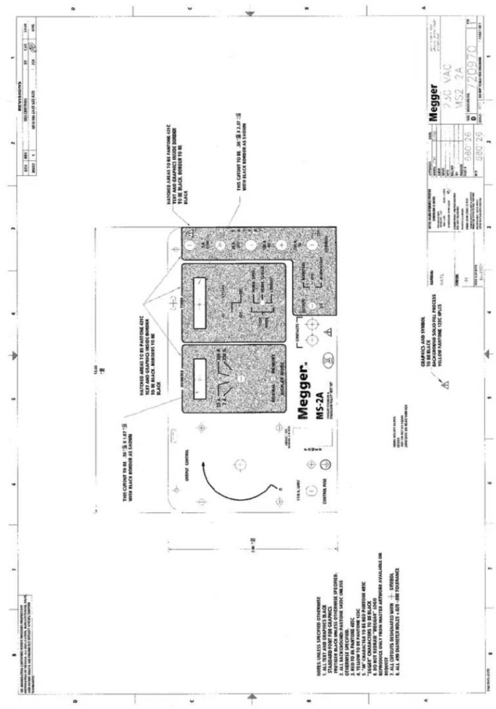
SCHEMATIC DRAWINGS
| REV. | DATE: 2014-03-24 | SCH. DAIGRAM MS2A | SCH. DAIGRAM MS2A | |
| C | 7401.12 | 0 | ||
| C | 2014-03-24 | 2014-03-24 | ||
| SCH. DAIGRAM MS2A | ||||
| SCH. DAIGRAM MS2A | ||||
| SCH. DAIGRAM MS2A | ||||
| SCH. DAIGRAM MS2A | ||||
| SCH. DAIGRAM MS2A | ||||
| SCH. DAIGRAM MS2A | ||||
| SCH. DAIGRAM MS2A | ||||
| TCEB5 | 9588 | 024E | SETD5 | KDP | E2 | ADE2 |
| PCB5 | LRC6 | MBOX | CJDX | QBC | AC'10 | VCS 5 AN11 |
| =E2 | +YCH | +AX | +TACH | -XX | MABBA | NOTBEA |

| 1 | 20051 | 06/27/08 | 2008 |
| 2 | 2006 | 03/09 | 2008 |
CITAMEHCS DRAWINGS

SCHEMATIC DRAWINGS
- HIGH CURRENT TEST SET
- MODEL MS-2A
- APPRECIATION
- IMPORTANT
- TABLE OF CONTENTS
- SECTION PAGE
- INTRODUCTION
- WARNING
- CAUTION
- DESCRIPTION OF CONTROLS
- POWER ON/OFF
- OUTPUT
- NOTE:
- MOMENTARY Position:
- MAINTAIN
- OFF Position:
- NORMAL Position:
- MEMORY Position:
- CYCLES Position:
- Position:
- SELECTION OF OUTPUT TERMINAL
- OVERLOAD CAPACITY
- EXAMPLE:
- STORAGE AND OPERATION CONDITIONS
- TEST PROCEDURE FOR TIME DELAY OF MOTOR OVERLOAD RELAYS
- IMPORTANT NOTE
- TEST PROCEDURE FOR
- INSTANTANEOUS ELEMENT OF MOTOR OVERLOAD RELAYS
- THERMAL ELEMENT OF MOLDED CASE CIRCUIT BREAKERS
- INSTANTANEOUS ELEMENT OF MOLDED CASE CIRCUIT BREAKERS
- CIRCUIT BREAKER GROUND FAULT TRIP DEVICES
- OVERLOAD DEVICES MAINTENANCE DATA
- MAINTENANCE OF MOLDED CASE CIRCUIT BREAKERS
- PLANNED MAINTENANCE PROGRAM
- Clean
- Tighten Connections
- Test
- MAINTENANCE OF MOTOR OVERLOAD RELAYS
- APPLICATION
- TYPES
- Inspect Heater Size
- Inspect Settings (Where applicable)
- Test
- SERVICE DATA
- SERVICING
- Enclosure:
- Control Panel:
- Variable Autotransformer:
- Other Components:
- Insulation:
- SERVICE AND REPAIR ORDER INSTRUCTIONS
- PREPARATION FOR RESHIPMENT
- WARRANTY STATEMENT
- ENVIRONMENTAL CONDITIONS
- OPERATIONAL ERRORS/TROUBLESHOOTING
- Difference in Memory/Normal ammeter readings:
- PARTS LIST
- Model MS-2A Portable High Current Test Set
- NOTES:
- INDEX
- SCHEMATIC DRAWINGS
- CITAMEHCS DRAWINGS
Brand : Megger
Model : MS-2A
Category : Measurement