
48BTCAN65 - Soundbar KICKER - Free user manual and instructions
Find the device manual for free 48BTCAN65 KICKER in PDF.


User questions about 48BTCAN65 KICKER
0 question about this device. Answer the ones you know or ask your own.
Ask a new question about this device
Download the instructions for your Soundbar in PDF format for free! Find your manual 48BTCAN65 - KICKER and take your electronic device back in hand. On this page are published all the documents necessary for the use of your device. 48BTCAN65 by KICKER.
USER MANUAL 48BTCAN65 KICKER
6.5" Powered Bluetooth® Speakers
natural_image
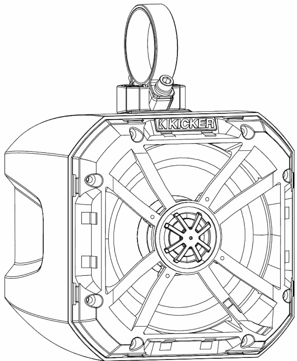
Technical line drawing of a KIKICKER airship with visible fan blades and mounting bracket (no text or symbols beyond branding)select language
seleccione el idioma
choisir la langue
sprache auswählen




Contents
Overview......2
Specifications....3
Installation 5
Power & Auxiliary Wiring......5
Switch Install 6
LED Grille Wiring....7
Speaker Wiring....7
Mounting....9
Operation....11
Multi-Function Button......11
Status LED....12
Setting Input Source ...... 13
Line Output & AUX IN ..... 13
Remote Control Install......14
Remote Control Operation ... 16
Troubleshooting ..... 17
Warranty 18
IMPORTANT SAFETY WARNING
PROLONGED CONTINUOUS OPERATION OF AN AMPLIFIER, SPEAKER, OR SUBWOOFER IN A DISTORTED, CLIPPED OR OVER-POWERED MANNER CAN CAUSE YOUR AUDIO SYSTEM TO OVERHEAT, POSSIBLY CATCHING FIRE AND RESULTING IN SERIOUS DAMAGE TO YOUR COMPONENTS AND/OR VEHICLE. AMPLIFIERS REQUIRE UP TO 4 INCHES (10CM) OPEN VENTILATION. SUBWOOFERS SHOULD BE MOUNTED WITH AT LEAST 1 INCH (2.5CM) CLEARANCE BETWEEN THE FRONT OF THE SPEAKER AND ANY SURFACE. KICKER PRODUCTS ARE CAPABLE OF PRODUCING SOUND LEVELS THAT CAN PERMANENTLY DAMAGE YOUR HEARING! TURNING UP A SYSTEM TO A LEVEL THAT HAS AUDIBLE DISTORTION IS MORE DAMAGING TO YOUR EARS THAN LISTENING TO AN UNDISTORTED SYSTEM AT THE SAME VOLUME LEVEL. THE THRESHOLD OF PAIN IS ALWAYS AN INDICATOR THAT THE SOUND LEVEL IS TOO LOUD AND MAY PERMANENTLY DAMAGE YOUR HEARING. PLEASE USE COMMON SENSE WHEN CONTROLLING VOLUME.
The PowerCan is the next generation in mobile audio systems, combining the innovations of new transfer protocols with KICKER's finest speaker and amp performance. This audio system has everything you need ready to roll right out of the box. Bluetooth 5.0 and AUX Input, integrated amplifier, RGB lighting, line output, and a wired remote control built to mount in a standard marine panel. And at its heart, the high-powered amp and 6.5" speakers pack a punch with KICKER signature quality audio.
Use the following instructions to install and operate your PowerCan and PowerCan Remote.
Specifications
Model: BTCAN65
| Power Output | 75W x 2 |
| @ 14.4V, <10% THD+N | |
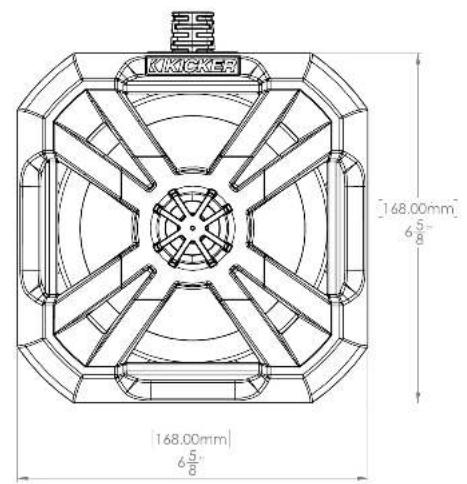
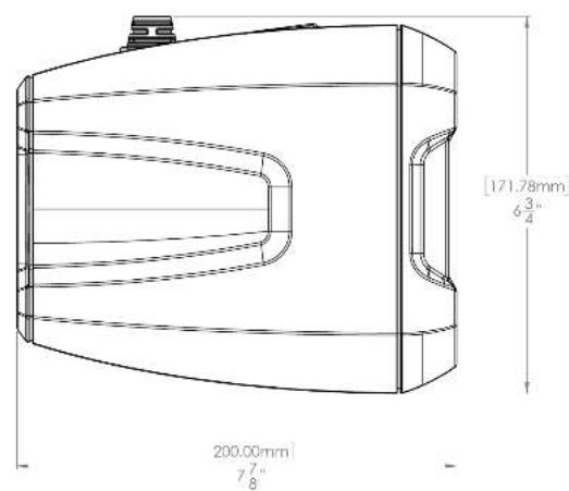
| Height [in, mm] 6-5/8, 168 | |
| Width [in, mm] 6-5/8, 168 | |
| Depth [in, mm] 7-7/8,200 | |
| Weight [lbs, kg] 13.6, 6.2 | |
| Woofer [in, mm] 6-1/2, 160 | |
| Tweeter [in, mm] 1, 25 | |
| Wiring Harness Length [ft, m] 12, 3.66 | |
| Frequency Response [Hz] 80-20K | |
| Signal-to-Noise Ratio >102, A-weighted,re: rated power | |
| Tweeter Magnet Material Neodymium | |
| Tweeter Dome Material Titanium | |
| Tweeter Design | Dome |
| Woofer Cone Material | Polypropolene |
| Woofer Surround Material | Santoprene |
| Aux Input | Stereo 3.5mm Female1.0 V Sensitivity |
| Line Output | Stereo 3.5mm FemaleBuffered, 1V |
Primary
(Right)
![[200.00mm] 77 B 187.78mm 73 B](/content/2026/05/998883/images/b8b976f9d4b8fb214bad15a3f3ad15558b1f9f42da818540c65a1b55bae69f23.jpg)
Secondary
(Left)
![KKICKER [168.00mm] 6 5/8" [168.00mm] 6 5/8"](/content/2026/05/998883/images/dd20b602e8406884f9bf44f89bb61ff3693015096f554955d8efcea127a1c13b.jpg)
Power & Auxiliary Wiring
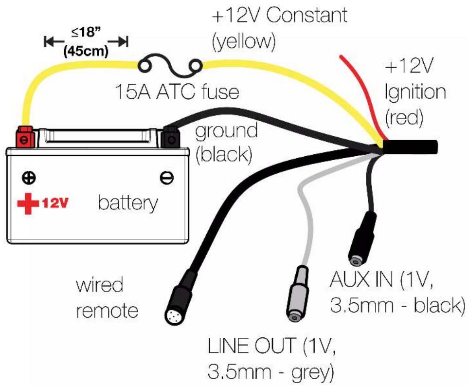
Disconnect the vehicle's battery to avoid an electrical short. Run the black ground wire to a paint-and-corrosion-free, solid, metal area of the vehicle's chassis or the negative battery terminal. Crimp the provided 5/16" ring terminal to the ground wire. The ring terminals have been left off so that power and ground wires may be run through vehicle tubing. Do not install the ring terminals until all wires have been run to their final location.
Run the yellow +12V constant wire to the battery location. Crimp the provided 15A ATC fuse to the yellow wire, which includes a heat-shrink butt connector. Once mechanically crimped, apply heat to the connector to create a secure, insulated connection. Then securely connect the fuse's 5/16" ring terminal to the positive battery terminal. Note that while the ring terminals can be cut off if necessary, the fuse should always be kept within 18 inches of the battery.
Connect the Red +12V Ignition Wire to the switched ignition power source, dash-mounted switch, accessory or relay switch.
Switch Install
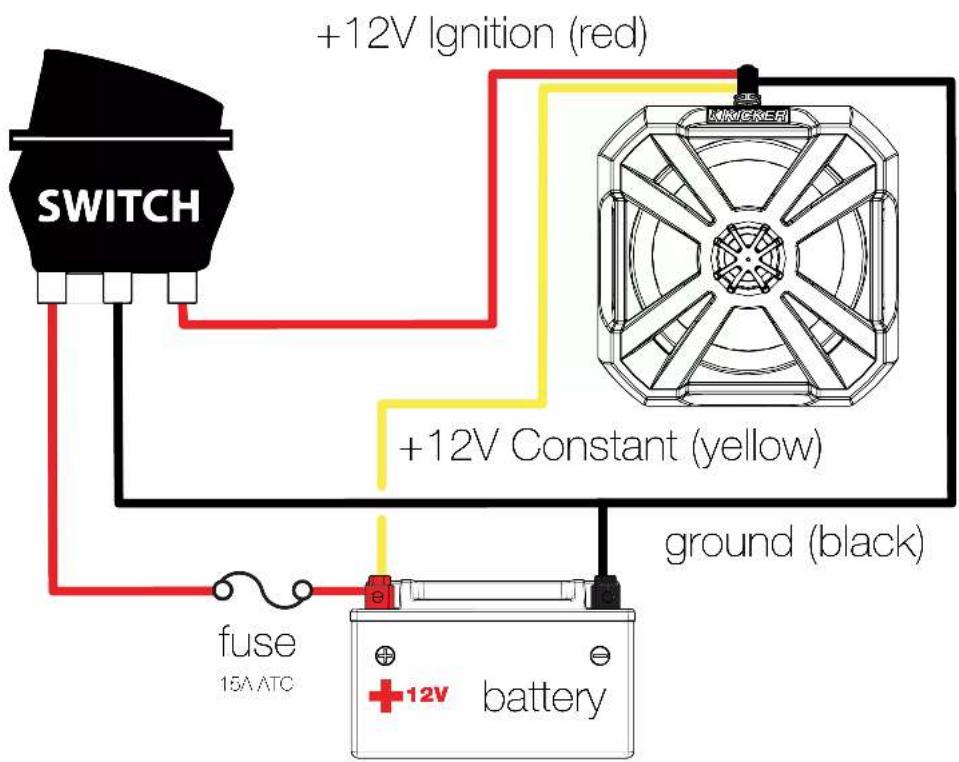
If you'd like to use a switch to control power to your PowerCan, wire it according to the following diagram.
Speaker Wiring
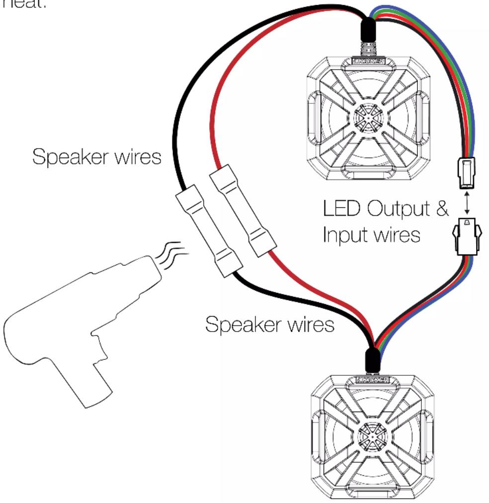
The speaker wiring for the PowerCan comes pre-installed with heat-shrink butt connectors on the Right PowerCan for a fast and secure connection. Connect the Right PowerCan's speaker wire to the left PowerCan's speaker wire, then crimp and apply heat.
LED Grille Wiring
- Connect the LED Output of the Right PowerCan (female plug), located on the smaller wire loom, to the LED Input (male plug) of the Left PowerCan.
- To control LED Grille behavior, install the KICKER KMLC (sold separately) by connecting the male LED plug of the Right PowerCan, located on the larger wire loom, to the KMLC female plug.

natural_image
Diagram showing two types of cable connectors connected via a bidirectional arrow (no text or symbols present)- If you're not using the KMLC, use the included RGB Pigtail to hard-wire your LED. Connect the RGB Pigtail to the male LED plug of the Right PowerCan.
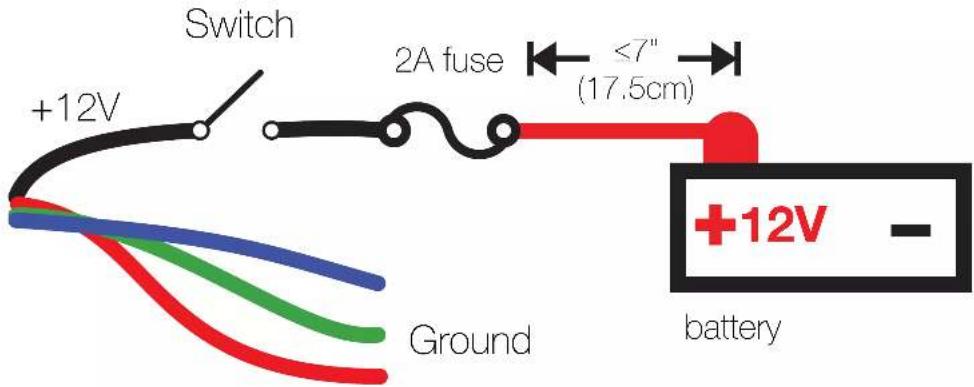
When hard-wiring the LED lighting, the black lead is +12V and the blue, red and green leads are ground.
Connect the black LED wire to the positive terminal of the battery.
a. Place a 2-amp fuse (not included) no further than 7" away from the battery terminal.
b. Install a switch (not included) on the black LED wire between the fuse and the speaker, so the LED's can be turned off. Without a switch to turn them off, they will always be on.
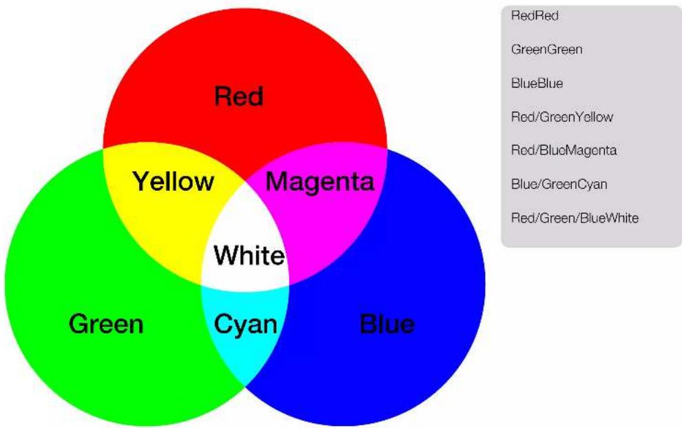
Connect the red, blue and/or green LED wires to the negative terminal of the battery. See the Venn diagram below for available combinations.
other
| Category | Count | | ---------------- | ----- | | Red | 1 | | Green | 1 | | Blue | 1 | | Yellow | 1 | | Cyan | 1 | | Magenta | 1 | | White | 1 |Mounting
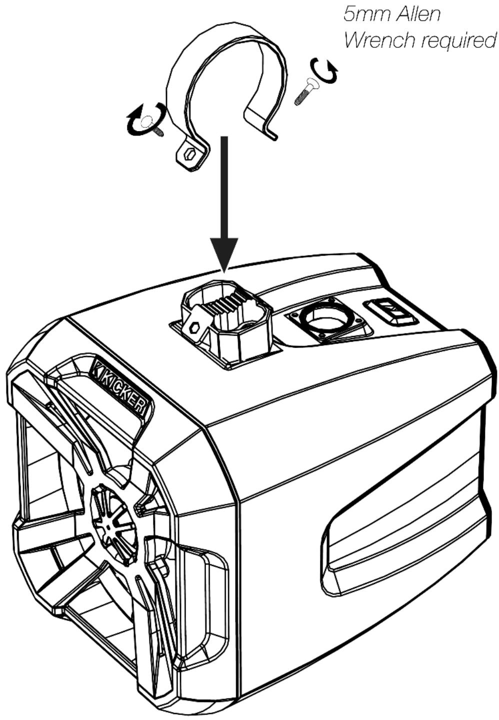
The PowerCan mounts out-of-the-box to round bars with the included 1.5", 1.75", and 2" diameter Bar Clamps. Use the KPB Square Clamps (47KPBSQ), sold separately, to mount your PowerCan to square bars. Choose a structurally sound location to mount the PowerCan. The Mounting Base may be rotated ±30° to accommodate some curved bars. Make sure there are no items interfering with the route of the wiring. Installation tools are not provided. 5mm and 6mm Allen Wrenches are required. Using mounting hardware, including clamps and screws, not provided by KICKER will result in a voided warranty.
- Screw the Mounting Bases to the PowerCan using the Mounting Screws.
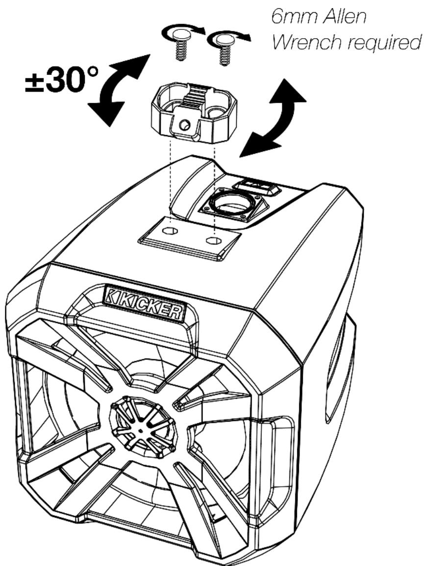
- Place the included rubber inserts in the Clamp Rings for improved vibration dampening, then install the Clamp Rings around your bar, securing them to the Mounting Bases using the Clamp Screws.
Multi-Function Button
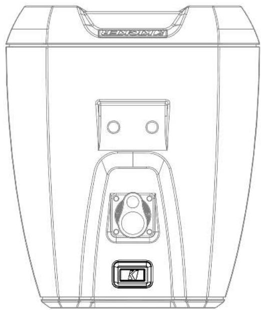
Use the multi-function button on top of the Right PowerCan for basic controls.

short press

1S
long press

10S
very long press

double-press
natural_image
Technical line drawing of a device casing with internal components and mounting bracket (no text or symbols)Short Press - Change Input Source Long Press - Enter Pairing Mode Very Long Press - Software Reset Double-Press - Play/Pause

A Software Reset will restore the PowerCan to factory settings and wipe the Bluetooth device list.
Status LED
The LED color displays audio source, pairing status, and warnings:
Off Remote Input wire is low
Blue Bluetooth Mode
Blue Blinking Bluetooth Pairing Mode
Red AUX Mode
Red Constant Blinking
Red Double Blinking
Red Triple Blinking
Over-Temperature / Amp Error
Under Voltage
Over Voltage
Setting Input Source
Short Press the Multi-Function button to switch between Bluetooth (blue) and AUX IN (red) input sources.
To enter Bluetooth Pairing Mode, Long Press the Multi-Function button. The STATUS LED will begin to flash blue. You may exit pairing mode at this stage by short pressing the Multi-Function button.
To finish pairing, from your audio device select 'BT CANS KICKER'. When successfully connected, the STATUS LED will be solid blue. When the PowerCan powers on in, or enters, Bluetooth mode, it will automatically begin to search for and connect with the last connected device.
Line Output & AUX IN
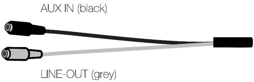
To use an external audio device as your input source, connect it to the AUX IN jack using a 1/8" (3.5mm) AUX cable, then set your input source to AUX IN. If the Wired Remote is not installed, use your audio device to control volume.
To send a line-level signal, connect a 1/8" (3.5mm) AUX cable from the Line Output of the PowerCan to your external audio device's line-level input.
Remote Control Install
The PowerCan Remote installs seamlessly into Carling-style cutouts. If performing a custom install, make sure there are no electronics or mechanisms behind the surface area into which you will cut. The mounting hole dimensions are H37mm X W22mm.
Remote Cutout Dimensions:
H: 1.45 inches, 36.83mm
W: .85 inches, 21.59mm
![.85" [21.59mm] 1.45" [36.83mm]](/content/2026/05/998883/images/e60a7e0da126de4271f151715bdd03d2b4d909f01cf90f1ec511091d62a920a8.jpg)
The Wired Remote is not required to use the PowerCans. If the remote isn't connected, volume levels will be controlled from your audio device.
IMPORTANT: If the wired remote is not used, keep the cap on the plug to prevent water from damaging the system
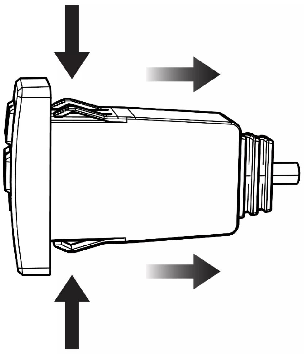
Push the PowerCan Remote into the cutout, depressing the tabs on the top and bottom, until the PowerCan Remote is secured in the mounting hole cutout (you may not hear a click).
natural_image
Technical diagram of a mechanical component with directional arrows indicating flow or movement (no text or symbols)Route the PowerCan remote wire to the remote input from the Right PowerCan's larger wire loom.
Remote Control Operation

short press

long press

10S
very long press

double-press
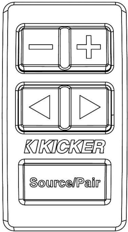
Source/Pair
Short Press - Change Input Source Long Press - Enter Pairing Mode Very Long Press - Software Reset Double-Press - Play/Pause

Short Press - Increase Volume by 1 step Long Press - Raise Volume until max
Short Press - Decrease Volume by 1 step Long Press - Lower Volume until muted

Short Press - Next Track Long Press (Bluletooth) - Fast Forward Long Press (AUX) - Raise LED Brightness

Short Press - Previous Track Long Press - Rewind Long Press (AUX) - Decrease LED Brightness
Troubleshooting
If the PowerCan becomes frozen or stuck, does not appear to be working, or gives an error code, check the obvious things first such as blown fuses, poor or incorrect wiring connections, etc.
No power? With a Volt Ohm Meter (VOM) check the following: ①+12 volt power terminal (should read +12V to +16V) ②Check for reversed power and ground connections ③Check Ground terminal for proper conductivity. ④Check fuses. ⑤Check that red & yellow ignition wire both have +12V.
Power on, no signal? Check the following: ① AUX In/Out connections and cables ② Test audio source signal, either with a "known good" output device or other means. ③ Audio source volume & PowerCan output volume are increased.
Bluetooth device will not connect? On your mobile device: ①Turn Bluetooth off, then on again. ②Remove 'BT CANS KICKER' from the Bluetooth menu. Then pair again (see page 11). ③Move your mobile device closer to the speaker. Avoid obstacles that may block the wireless signal. ④Perform a software reset by pressing and holding the PLAY/PAUSE button for 10 seconds (Bluetooth devices must be re-paired after software reset).
No or low output? ① Check the settings on the audio source. ② Check the speaker wiring, including AUX input and Line-level connections.
PowerCan frozen or stuck in operating procedure? ① Perform a software reset on the PowerCan ② Cycle the power.
No Remote Function? ① Check wiring. ② Cycle the power.
CAUTION: When jump starting the vehicle, be sure that connections made with jumper cables are correct. Improper connections can result in blown fuses as well as the failure of other critical systems in the vehicle.
If you have more questions about the installation or operation of your new KICKER product, see the Authorized KICKER Dealer where you made your purchase. For more advice on installation, click on the SUPPORT tab on the KICKER homepage, www.KICKER.com. Choose the TECHNICAL SUPPORT tab, choose the subject you are interested in, and then download or view the corresponding information. Please E-mail support@KICKER.com or call Technical Services (405) 624-8583 for unanswered or specific questions.
When purchased from an Authorized KICKER Dealer, KICKER warrants this product to be free from defects in material and workmanship under normal use for a period of TWO (2) YEARS from date of original purchase with receipt. If this product is identified as "Refurbished" or "B Goods", the warranty is limited to a period of THREE (3) MONTHS from the date of original purchase. In all cases you must have the original receipt. Should service be necessary under this warranty for any reason due to manufacturing defect or malfunction during the warranty period, KICKER will repair or replace (at its discretion) the defective merchandise with equivalent merchandise. Warranty replacements may have cosmetic scratches and blemishes. Discontinued products may be replaced with more current equivalent products. This warranty is valid only for the original purchaser and is not extended to owners of the product subsequent to the original purchaser. Any applicable implied warranties are limited in duration to a period of the express warranty as provided herein beginning with the date of the original purchase at retail, and no warranties, whether express or implied, shall apply to this product thereafter. Some states do not allow limitations on implied warranties; therefore, these exclusions may not apply to you. This warranty gives you specific legal rights; however you may have other rights that vary from state to state.
WHAT TO DO IF YOU NEED WARRANTY OR SERVICE:
Defective merchandise should be returned to your local Authorized Stillwater Designs (KICKER) Dealer for warranty service. Assistance in locating an Authorized Dealer can be found at www.KICKER.com or by contacting Stillwater Designs directly. You can confirm that a dealer is authorized by asking to see a current authorized dealer window decal.
If it becomes necessary for you to return defective merchandise directly to Stillwater Designs (KICKER), call the KICKER Customer Service Department at (405) 624-8510 for a Return Merchandise Authorization (RMA) number. Package only the defective items in a package that will prevent shipping damage, and return to:
Stillwater Designs
3100 North Husband St
Stillwater, OK 74075
The RMA number must be clearly marked on the outside of the package. Please return only defective components. The return of functioning items increases your return freight charges. Non-defective items will be returned freight-collect to you. For example, if a subwoofer is defective, only return the defective subwoofer, not the entire enclosure. Include a copy of the original receipt with the purchase date clearly visible, and a “proof-of-purchase” statement listing the Customer’s name, Dealer’s name and invoice number, and product purchased. Warranty expiration on items without proof-of-purchase will be determined from the type of sale and manufacturing date code. Freight must be prepaid; items sent freight-collect, or Cash-On-Demand, will be refused.
WHAT IS NOT COVERED?
This warranty is valid only if the product is used for the purpose for which it was designed. It does not cover:
o Damage due to improper installation
o Subsequent damage to other components
o Damage caused by exposure to moisture, excessive heat, chemical cleaners, and/or UV radiation
o Damage through negligence, misuse, accident or abuse. Repeated returns for the same damage may be considered abuse
o Any cost or expense related to the removal or reinstallation of product
o Speakers damaged due to amplifier clipping or distortion
o Items previously repaired or modified by any unauthorized repair facility
o Return shipping on non-defective items
o Products with tampered or missing barcode labels
o Products with tampered or missing serial numbers
o Products returned without a Return Merchandise Authorization (RMA) number
o Products purchased from an UNAUTHORIZED dealer
o Freight Damage
o The cost of shipping product to KICKER
o Service performed by anyone other than KICKER
HOW LONG WILL IT TAKE?
KICKER strives to maintain a goal of one week turnaround for all electronics (amplifiers, crossovers, equalizers, etc.) returns. Delays may be incurred if lack of replacement inventory or parts is encountered. Failure to follow these steps may void your warranty. Any questions can be directed to the KICKER Customer Service Department at (405) 624-8510. Contact your International KICKER dealer or distributor concerning specific procedures for your country's warranty policies.
KICKER® BT Cans
Info Card | Tarjeta de Información | Carte Info | Infokarte
KKICKER®
IMPORTANT: KICKER recommends a
professional installation performed by authorized retailers. You are solely responsible for safely mounting and wring your products.
Scan here for
owner's manual
Thank you and congratulations on your purchase of the KICKER BT Cans Speaker System! The BT Cans are the next generation in mobile audio systems, combining the innovations of new transfer protocols with KICKER's finest speaker and amp performance. This audio system has everything you need ready to roll right out of the box. Bluetooth and AUX input, integrated amplifier, RGB lighting, line output, and a remote control built to mount in a standard marine panel. And at its heart, the high-powered amp and 6.5" speakers pack a punch with KICKER signature quality audio.
Sincerely
Steve Iroy
President/CEO

Install the included 15A fuse on the Yellow +12V Constant wire within 18" of the battery. Connect the battery ring terminals of the Yellow +12V Constant and Black Ground wires to the battery. Connect the Red +12V Ignition Wire to the switched ignition power source, or dash-mounted switch. Using the included splice connectors, connect the right speaker to the left speaker. Connect the male LED plug (4-pin molex) to the female LED plug (4-pin molex). Use the KMLC (sold separately) to control the RGB LED lighting. Connect the remote control to the remote input. Mount the remote control in your vehicle.
Use the multi-function button on the Right.
BT65 to control.
Short Press - Source
Long Press - Pairing
Very Long Press - Reset
Double-Press - Play/Pause
Appui court - Source
Appui long - Appairage
Press and hold the Source/Pair button of the remote, or the multi-function button of the Right BT65, to enter Bluetooth pairing mode. The LEDs will begin to blink blue. Select BT CANS KICKER from your list of Bluetooth devices. Once successfully paired, the LEDs will turn solid blue. Please see the owner's manual for more installation and operation instructions. Remote not required for operation. Remote uses Carling-style cutout.
- 6.5" Powered Bluetooth® Speakers
- Contents
- IMPORTANT SAFETY WARNING
- Specifications
- Power & Auxiliary Wiring
- Switch Install
- Speaker Wiring
- LED Grille Wiring
- Mounting
- Multi-Function Button
- Status LED
- Setting Input Source
- Line Output & AUX IN
- Remote Control Install
- Remote Control Operation
- Source/Pair
- Troubleshooting
- WHAT TO DO IF YOU NEED WARRANTY OR SERVICE:
- WHAT IS NOT COVERED?
- HOW LONG WILL IT TAKE?
- KICKER® BT Cans
- Info Card | Tarjeta de Información | Carte Info | Infokarte
- KKICKER®
Brand : KICKER
Model : 48BTCAN65
Category : Soundbar