
D315AOB - Electronic board AVERMEDIA - Free user manual and instructions
Find the device manual for free D315AOB AVERMEDIA in PDF.


| Product Type | Carrier Board for NVIDIA® Jetson AGX Orin™ Module |
| Model Number | D315AOB |
| Compatible Module | NVIDIA® Jetson AGX Orin™ 32GB or 64GB |
| Dimensions | 181.5 mm (W) x 137 mm (L) x 88 mm (H) (with mounting holes) |
| Operating Temperature | -25°C to 65°C (D315AOB) |
| Storage Temperature | -40°C to 85°C |
| Relative Humidity | 95% @ 40°C, Non-Condensing |
| Power Input (DC Jack) | 12~54V DC, 7~1.95A (54V/2.78A adapter included) |
| Power Input (ATX 4-pin) | 12~54V DC, 10.8~2.4A |
| Networking | 1x GbE RJ-45, 1x 10GbE RJ-45, 1x M.2 E key (Wi-Fi 6E) |
| Display Output | 1x HDMI 2.1 (up to 8K60) |
| USB Ports | 2x USB 3.2 Gen 2 Type-A, 2x USB 2.0 Type-A, 1x USB 2.0 Micro-B (recovery) |
| Storage | 1x micro-SD card slot, 1x M.2 M key (SSD or capture card) |
| Expansion Headers | 40-pin (UART, SPI, CAN, I2C, I2S, GPIOs), 1x mPCIe (4G/5G), 1x PCIe x16 (x8 lanes), 120-pin (MIPI SerDes) |
| Audio | Intel HD Audio analog connector (9-pin header) |
| CAN Bus | 3-pin terminal block with transceiver |
| RTC Battery | CR2032 3V coin cell battery |
| Cooling | Heat sink with optional fan (12V PWM fan connector) |
| Buttons | Power button, Recovery button, DIP switch (SW1) |
| Certifications | CE, FCC, KC (pending) |
| Included Accessories | Power adapter (region-specific), fan module, power cord |
Frequently Asked Questions - D315AOB AVERMEDIA
/sys/devices/platform/pwm-fan/hwmon/hwmon2/pwm1.User questions about D315AOB AVERMEDIA
0 question about this device. Answer the ones you know or ask your own.
Ask a new question about this device
Download the instructions for your Electronic board in PDF format for free! Find your manual D315AOB - AVERMEDIA and take your electronic device back in hand. On this page are published all the documents necessary for the use of your device. D315AOB by AVERMEDIA.
USER MANUAL D315AOB AVERMEDIA
AVerMedia D315 series
Applies to NVIDIA ® Jetson AGX Orin 32G/64G module
AVerMedia Technologies, Inc.
No. 135, Jian 1st Rd., Zhonghe Dist., New Taipei City 23585, Taiwan
Tel: 886-2-2226-3630
Fax: 886-2-3234-4842
Sales and Marketing: Contact
Technical Support: Professional User
Table of Contents
1.0 Introduction......8
1.1 Product Specifications ____ 9
1.2 Product Overview 10
Block Diagram 10
Front View and Back View of Carrier board 10
1.3 Connector Summary 12
1.4 Carrier Board Interface 13
2.0 Feature Description.... 16
2.1 Jetson module Connector 16
2.2 Fan Power connector 16
2.3 RTC Battery Connector 17
2.4 HDMI OUTPUT 17
2.5 USB 3.2 Gen 2 Type-A Connector #1, #2 ____ 17
2.6 M.2 E key 2230 18
2.7 M.2 M key 2280 18
2.8 USB 2.0 Micro B Connector 18
2.9 Micro SD Card Slot 19
2.10 10 Gigabit Ethernet Connector 19
2.11 40-Pin expansion header ____ 20
2.12 Audio pin header 22
2.13 Gigabit Ethernet Connector 22
AVerMedia

NVIDIA
ELITE
PARTNER
2.14 Micro SIM Card Socket 23
2.15 Mini card socket 23
2.16 OOB board connector 24
2.17 54V DC POWER JACK____ 25
2.18 ATX 4P 25
2.19 USB 2.0 Gen 1 Type-A Connector #1, #2 ____ 26
2.20 12V power input connector for daughter board 26
2.21 PCIE x16 socket 27
2.22 Board to board connector (to Camera board) 27
2.23 CAN Bus 3-pin terminal block with transceiver ____ 27
2.24 Debug port 28
2.25 Switch Button 28
2.26 Power & Recovery Button 29
3.0 Installation.... 30
3.1 BSP Setup Instructions 30
4.0 Software 31
5.0 Force Recovery Mode.... 35
6.0 Accessory Drawings 36
6.1 Fan Module/ Adapter/ Power Cord 36
Preface
Disclaimer
The information contained in this user manual, including but not limited to any product specification is subject to change without notice. AVerMedia assumes no liability for any damages incurred directly or indirectly from any technical or typographical errors or omissions contained herein or for discrepancies between the product and the user manual.
Technical Support
If you experience the difficulty after reading this manual and/or using the product, please contact the reseller from which you purchased the product. In most cases, the reseller can help you with the product installation and the difficulty you encountered.
In case the reseller is not able to resolve your problem, our highly capable global technical support team can certainly assist you. Our technical support section is available 24 hours a day and 7 days a week through our website, with the click here. For more contact information, you may find it in the section of AVerMedia Global Offices.
Contact Enquiry
For more information of our products, pricing, and order placement, please fill in our inquiry form here, we will contact you within 24 hours.
Download User Manual
Please click the link here to download the file of this user manual from AVerMedia website.
Revision History
| Revision | Date | Updates |
| V01 | Sep 29, 2022 | 1st Released |
| V02 | Nov 08, 2022 | Update specification |
AVerMedia Global Offices
https://www.avermedia.com/professional/contact
Headquarters
Taiwan Office
No. 135, Jian 1st Rd., Zhonghe Dist., New
Taipei City 23585.Taiwan
Tel: +886-2-2226-3630
Fax: +886-2-3234-4842
Sales & Marketing: Contact
Technical Support: Home users /
Professional users
The Americas
USA Office
4038 Clipper Court Fremont, CA 94538
Tel: S (510) 403-0006
Fax: (510) 403-0022
Sales & Marketing: Contact
Technical Support: Home users /
Professional users
Brazil Office
Sales & Marketing: Contact
Technical Support: Home users /
Professional users
Latin America Office
Sales & Marketing: Contact
Technical Support: Home users /
Professional users
Europe
Head Office EU
AVT Solutions GmbH
S: technicalsupport_120
Sales & Marketing: Contact
Technical Support: Home users /
Professional users
Russia Office
Sales & Marketing: Contact
Technical Support: Home users /
Professional users
Professional Solutions Support Tel:
S+7 (925) 834-0310
Spain Office
AVerMedia Europe Group
S: technicalsupport_120
Sales & Marketing: Contact
Technical Support: Home users /
Professional users
Asia-Pacific
China Office
Room 1510, No.488, Hitech Plaza, South
Wuning Rd., Jingan District, Shanghai,
China
Tel: +86-021-5298 7985
Fax: +86-021-5298 7981
Sales & Marketing: Contact
Technical Support: Home users /
Professional users
Japan Office
6F.Kojimachi Syuei Bldg.4-3-13 Kudan-
minami, Chiyoda-ku, Tokyo, 102-0074,
Japan
Sales & Marketing: Contact
Technical Support: Home users /
Professional users
Limited Product Warranty
AVerMedia provides the one-year product warranty. Should this product, in AVerMedia's opinion, fail to be in the good working order during the warranty period, AVerMedia will, at its option, repair or replace it at no charge, provided that the product has not been subjected to abuse, misuse, accident, disaster, or non-AVerMedia authorized modification or repair.
You may obtain the warranty service by delivering this product to an authorized AVerMedia business partner or to AVerMedia along with the proof of purchase. Product returned to AVerMedia must be pre-authorized by AVerMedia with an RMA (Return Material Authorization) number marked on the outside of the package and sent prepaid, insured, and packaged for the safe shipment. AVerMedia will return the product by prepaid shipment service.
It is not recommended to disassemble the box PC, which will impact the warranty. The limited product warranty is only valid over the serviceable life of the product. This is defined as the period during which all components are available. Should the product prove to be irreparable, AVerMedia reserves the right to substitute an equivalent product if available or to retract the product warranty if no replacement is available.
The above product warranty is the only warranty authorized by AVerMedia. Under no circumstances will AVerMedia be liable in any way for any damages, including any lost profits, lost savings, or other incidental or consequential damages arising out of the use of, or inability to use, such product.
Copyright Notice
The information contained in this document is subject to change without notice. AVerMedia shall not be liable for errors contained herein or for incidental consequential damages in connection with the furnishing, performance, or use of this material. This document contains proprietary information that is protected by copyright. All rights are reserved. No part of this document may be photocopied, reproduced, or translated to another language without the prior written consent by AVerMedia.
Trademark Acknowledgement
AVerMedia acknowledges all the trademarks, registered trademarks, and/or copyrights referred to in this document as the property of their respective owners. Not listing all possible trademarks or copyright acknowledgments does not constitute the lack of acknowledgment to the rightful owners of the trademarks and copyrights mentioned in this document.
ESD Warning
Electronic components and circuits are sensitive to Electrostatic Discharge (ESD). When handling any circuit board assemblies including AVerMedia AVerMedia products, it is highly recommended that ESD safety precautions can be observed. ESD safe best practices can include, but are not limited to the following ones.
- Leave the circuit board in the antistatic package until it is ready to be installed.
- Use a grounded wrist strap when handling the circuit board. At a minimum, you need to touch a grounded metal object to dissipate any static charge, which may be present on you.
- Avoid handling the circuit board in the carpeted areas.
- Handle the board by the edges and avoid the contact [L] with the components.
- Only handle the circuit boards in ESD safe areas, which may include ESD floor and/or table mats, wrist strap stations, and ESD safe lab coats.
Safety Precaution:
- All cautions and warnings on the device should be noted.
- For safety consideration, do NOT open the device if not a qualified service stuff.
-
Place the device on a solid surface during installation to prevent falls.
-
Keep the device away from humidity.
-
Do NOT leave this device in an un-controlled environment with temperatures beyond the device's permitted storage temperature to avoid damage.
-
All adaptors and cables supplied by AVerMedia are verified. Do NOT use any others not supplied by AVerMedia to avoid any malfunction or fires.
-
Make sure the power source matches the power rating of the device.
-
Place the power cord where people cannot step on it. Do not put anything on the power cord.
-
Always completely disconnect the power while the device is not usage or idle for a long time.
-
Disconnect the device from any AC supply before cleaning. While cleaning, use a damp cloth instead of liquid or spray detergents.
-
Make sure the device is installed near a power outlet and easy for accessible.
-
Do not cover the openings on the device to ensure optimal heat dissipation.
-
Watch out the heatsink or heat spreader of the device when the system is running.
-
Never pour any liquid into the openings. This could cause fire or electric shock.
-
The static electricity should be noted while installing any internal components. Consider to use a grounding wrist strap and put all electronic parts in static-shielded containers.
If the following situations occur, please contact our service personnel:
(1) The device is dropped or damaged
(2) Damaged power cord or plug
(3) Exposure to moisture
(4) Liquid intrusion into the device
(5) Any obvious signs of damage displayed on the device
(6) Device is not working as expected or in a manner as described in this manual
AVerMedia

NVIDIA
ELITE PARTNER
1.0 Introduction
AVerMedia AVerMedia D315/D315AO/D315AOB include fully featured carrier board which is all developed for NVIDIA Jetson AGX Orin 32G/64G modules. D315/D315AO/D315AOB provide multiple I/O include one 4Kp60 HDMI video output, two USB 3.2 ports, one GbE, one 10G RJ-45 port, 40-pin expansion, one M.2 Key E, one M.2 key M.
Operating with NVIDIA ® Jetson AGX Orin 32G/64G modules and the rich I/O functions, AVerMedia D315/D315AO/D315AOB is the perfect choice for high-end performance AI edge computing platform for intelligent video analytics applications.
1.1 Product Specifications
| NVIDIA Jetson SoM | NVIDIA® Jetson AGX OrinTM module (32GB or 64GB) |
| Networking | 1x GbE RJ-451x 10G RJ-451x M.2 E key (for Wi-Fi 6E) |
| Display Output | 1x HDMI 2.1 (8K60) |
| Temperature | Operating temperature( TBD):-25°C~85°C (D315), -25°C~70°C (D315AO) and -25°C~65°C(D315AOB)Storage temperature -40°C ~ 85°CRelative humidity 40 °C @ 95%, Non-Condensing |
| MIPI & SerDes Camera (120-pin) | GMSL2/FPD-link III/V-by-One® HS (optional) |
| USB | 1x USB 2.0 Micro-B for recovery2x USB 2.0 Type-A2x USB 3.2 Type-A |
| Audio | Intel HD Audio analog connector |
| StorageExpansion Header | 1x micro-SD card slot |
| 40-pin (UART, SPI, CAN, I2C, I2S, GPIOs )1x M.2 M key (for SSD or AVerMedia capture card: CL312H1,CN311-H, CN312SW, CN312MW)1x Micro SIM socket1x mPCIe (for 4G LTE module or 5G module via adapter card)1x PCIe x16 (only support x8 PCIe lane)1x CAN bus with transceiver120-pin (for MIPI SerDes) | |
| Input Power | DC in jack on board: 54V/2.78A adapter, DC Range12~54V(7~1.95A)ATX 4-pin: 12~54V (10.8~2.4A) |
| Power CordThermal Solution | US/JP/EU/UK/TW/AU/CN |
| Heat sink with fan (optional) | |
| Buttons | Power and Recovery |
| RTC Battery | Support RTC Battery and Battery Life Monitoring by MCU |
| Dimensions | D315: 141.5mm (W) x 133.5mm (L) x 29mm (H)D315AO: 141.5mm(W) x 133.5mm(L) x 63mm(H)D315AOB: 181.5mm (W) x 137mm (L) x 88mm (H) (with mounting hole) |
| Certifications | CE, FCC, KC (To be applied |
1.2 Product Overview
Block Diagram
![graph TD A["DC Jack P4 Wafer"] --> B["Power Circuit"] B --> C["CR2032"] C --> D["4P Header"] D --> E["MSD CARD"] E --> F["EEPROM"] F --> G["Audio Codec A[C3101"] G --> H["MIC In Speaker out"] H --> I["3P Connector"] I --> J["CAN Bus Transceiver IFX1050GXD"] J --> K["HINE4 90 pins"] B --> L["SYS_VIN_…](/content/2026/05/998778/images/4cdc71bcf1452bb96b71f743c270f6015210c260f9fcd0f2c2378db4515d85bf.jpg)
AVerMedia

NVIDIA
ELITE PARTNER
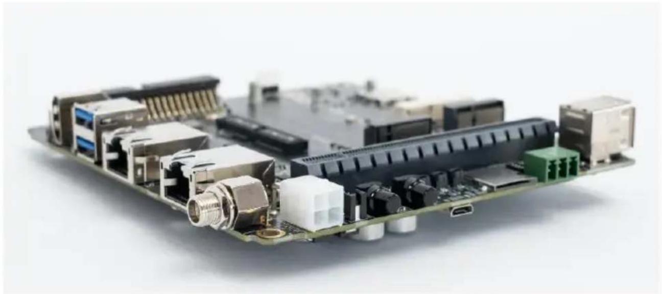
Front View and Back View of Carrier board


1.3 Connector Summary
| J1 | 699-pin high-speed/high-density connector |
| J2 | Fan Wafer |
| J3 | External RTC Battery wafer |
| J4 | HDMI output Type-A Vertical Side Connector (Female) |
| J5 | USB 3.2 Gen2 Dual Port Type A Connector |
| J6 | M.2 E-Key Socket |
| J7 | M.2 M-Key Socket |
| J8 | USB 2.0 Micro B Connector |
| J9 | Micro SD Card Socket (Push-Push) |
| J13 | 10 Gigabit Ethernet Connector w/LEDs |
| J14 | 40-pin Expansion |
| J15 | Audio 9-pin header |
| J16 | Gigabit Ethernet Connector w/LEDs |
| J17 | Micro SIM card socket (Push-Push) |
| J22 | Mini card socket |
| J26 | OOB board connector (5V) |
| J27 | OOB board connector (Reset) |
| J28 | OOB board connector (Power) |
| J30 | DC power Jack with Lock |
| J31 | Input Power – 4.2mm Pitch 90° ATX Power 4P |
| J33 | USB 2.0 Gen1 Dual Port Type A Connector |
| J37 | DC 12V connector for daughter board |
| J38 | PCIE x16 socket |
| J60 | 120-pin high speed board to board connector (to Camera board) |
| BJ3 | CAN bus 3-pin terminal block with transceiver |
1.4 Carrier Board Interface
Top View Interface
| J1 | 699-pin high-speed/high-density connector |
| J2 | Fan Wafer |
| J3 | External RTC Battery wafer |
| J8 | USB 2.0 Micro B Connector |

| J31 | Input Power – 4.2mm Pitch 90° ATX Power 4P |
| J33 | USB 2.0 Gen1 Dual Port Type A Connector |
| J37 | 12V Power input for sub board |
| J38 | PCIE X16 connector |
| J60 | 2x60 pin high speed board to board connector (to Camera board) |
| BJ3 | CAN bus 3-pin terminal block with transceiver |
| JP8 | Debug port |
| SW1 | Switch Button |
| BSW1 | Power Button w/LEDs |
| BSW3 | Recovery Button w/LEDs |
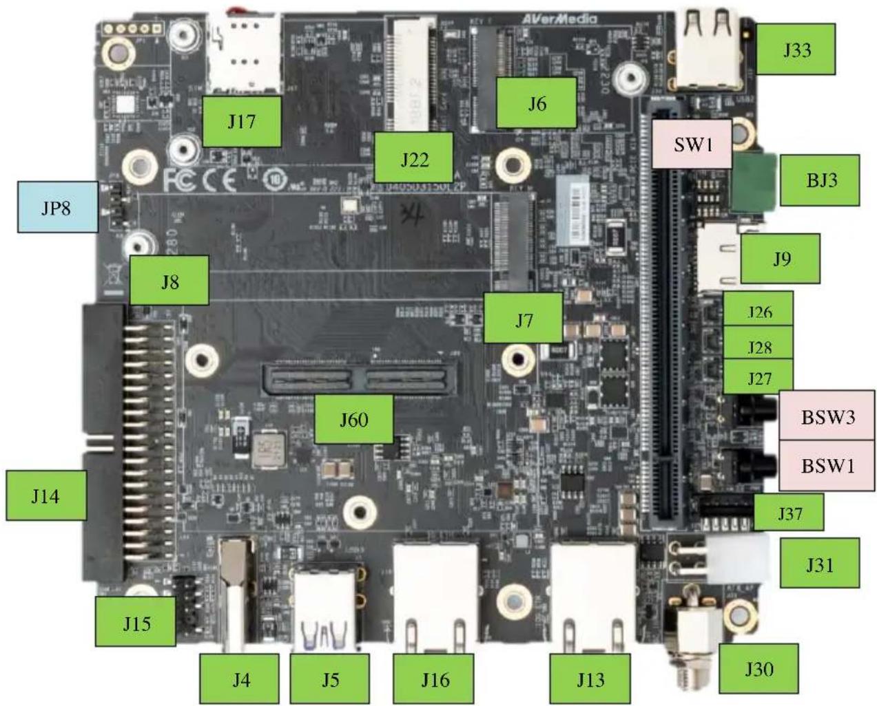
2.0 Feature Description
2.1 Jetson module Connector
| Function | Provide connection with NVIDIA® JetsonTM AGX XavierTM module |  | |
| Location | J1 | ||
| Type Description | MOLEX 699pin socket | ||
| Manufacturer and Part Number | MOLEX,203456-0003 | ||
| Mating Connector | MOLEX,203456-0003 | ||
| Pinout | Please refer to NVIDIA JetsonTM AGX OrinTM and AGX OrinTM System-on-Module datasheet for pinout details. | ||
| Remarks | https://developer.nvidia.com/ embedded/downloads | ||
2.2 Fan Power connector
| Function | Fan Power Connector | 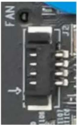 | ||
| Location | J2 | |||
| Type Description | WAFER_1*4PIN_1.25 mm_90° | |||
| Manufacturer and Part Number | ACES 50271-0040N-001_BLACK | |||
| Mating Connector | ACES 50276-004H0H0-001 | |||
| Pinout | Pin # | Description | ||
| PIN 1 | GND | |||
| PIN 2 | +12V Power | |||
| PIN 3 | FAN_TACH | |||
| PIN 4 | FAN_PWM | |||
| Remarks | None | |||
2.3 RTC Battery Connector
| Function | RTC battery for module | 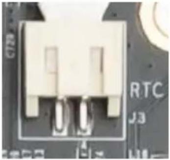 | ||
| Location | J3 | |||
| Type Description | 2.0mm wire-to-board header 02P type | |||
| Manufacturer and Part Number | Pinrex, 721-94-02TWR9 | |||
| Mating Connector | Tyu, TU2001HNO-02 | |||
| Pinout | Pin # | Description | ||
| PIN1 | 3V Power | |||
| PIN2 | GND | |||
| Remarks | RTC Battery:, CR2032 3V | |||
2.4 HDMI OUTPUT
| Function | HDMI output connector |  |
| Location | J4 | |
| Type Description | HDMI Type-A female connector | |
| Manufacturer and Part Number | 捷湧 EDL TECHNOLOGY CO. HM-FVD480B | |
| Mating Connector | Any HDMI standard Type-A interface cable or device. | |
| Pinout | Please refer to HDMI standard. | |
| Remarks | None | |
2.5 USB 3.2 Gen 2 Type-A Connector #1, #2
| Function | USB 3.2 Gen 2 Type-A connector #1 #2 | 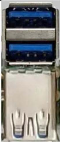 | |
| Location | J5 | ||
| Type Description | Dual-port USB 3.2 Gen 2 Type-A female connector | ||
| Manufacturer and Part Number | 冠泰 ChampwayCU3B-AFR15U-096H | ||
| Mating Connector | Any USB 3.2 Gen 2 standard Type-A interface cable or device. | ||
| Pinout | Please refer to USB 3.2 Gen 2 standard. | ||
| Remarks | None | ||
2.6 M.2 E key 2230
| Function | M.2 E key |  |
| Location | J6 | |
| Type Description | SOCKET_M.2-KEY E_75PIN_90°_SMD | |
| Manufacturer and Part Number | 宏致ACES51748-07502-005_P0.5 H8.5 | |
| Mating Connector | Any M.2 E key 2230 card standard interface device. | |
| Pinout | Please refer to M.2 E key card standard for the pinout details. | |
| Remarks | None | |
2.7 M.2 M key 2280
| Function | M.2 M key | 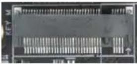 |
| Location | J7 | |
| Type Description | SOCKET_M.2-KEYM_75PIN_90°_SMD | |
| Manufacturer and Part Number | 宏致_ACES51757-0750C-012_P0.5 mm-H5.5 mm | |
| Mating Connector | Any M.2 M key 2280 card standard interface device. | |
| Pinout | Please refer to M.2 M key card standard for the pinout details. | |
| Remarks | None | |
2.8 USB 2.0 Micro B Connector
| Function | BSP Installation as recovery mode |  |
| Location | J8 | |
| Type Description | USB micro-type B female connector | |
| Manufacturer and Part Number | 福軒 FullgloryFG-MCB-111440 | |
| Mating Connector | Any USB standard Micro-type interface cable or device. | |
| Pinout | Please refer to USB Micro-type standard. | |
| Remarks | None | |
2.9 Micro SD Card Slot
| Function | Micro SD Card |  |
| Location | J9 | |
| Type Description | SOCKET_MICRO SDCARD_9PIN_90°_SMD | |
| Manufacturer and Part Number | 福軒 FullgloryFG-0011BAAS09A | |
| Pinout | Refer to MicroSD card standard | |
| Remark | Push-Push | |
2.10 10 Gigabit Ethernet Connector
| Function | 10 Gb single-port Ethernet connector, used to connect to the host system. | 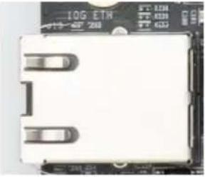 |
| Location | J13 | |
| Type Description | RJ45 with integrated magnetics | |
| Manufacturer and Part Number | 志展 Compupack(CPC)ACNRJJA0001-00610G-LEFT(G/Y)+RIGHT(Y)-UP | |
| Mating Connector | Any standard 10Gb Ethernet mating connector can be applicable. | |
| Pinout | Comply with Ethernet standards. | |
| Remarks | None | |
2.11 40-Pin expansion header
| Function | General-purpose input/output |  | ||||
| Location | J14 | |||||
| Type Description | HEADER_BOX_2*20PIN_2.54 mm_90°_SMD | |||||
| Manufacturer and Part Number | 志展 Compupack(CPC)ACNBH420029-040 | |||||
| Mating Connector | Any 2.54mm pitch standard interface female | |||||
| Pinout | [PCB Ver.A] | |||||
| Sysfs GPIO | Connector Label | Pin | Pin | Connector Label | Sysfs GPIO | |
| 3.3 VDC | 40 | 39 | 5.0 VDC | |||
| /dev/i2c-7 | I2C_GP8_DAT | 38 | 37 | 5.0 VDC | ||
| I2C_GP8_CLK | 36 | 35 | GND | |||
| gpio454 | MCLK05 | 34 | 33 | UART1_TX | /dev/ttyTHS0 | |
| GND | 32 | 31 | UART1_RX | |||
| SFIO (gpio460) | UART1_RTS | 30 | 29 | I2S2_CLK | gpio398 | |
| SFIO (gpio456) | PWM01 | 28 | 27 | GND | ||
| gpio433 | GPIO27_PWM2 | 26 | 25 | GPIO8_AO_DMIC_IN_DAT | gpio325 | |
| 3.3 VDC | 24 | 23 | GPIO35_PWM3 | gpio391 | ||
| gpio483 | SPI1_MOSI | 22 | 21 | GND | ||
| gpio482 | SPI1_MISO | 20 | 19 | GPIO17_40HEADER | gpio444 | |
| gpio481 | SPI1_SCK | 18 | 17 | SPI1_CS0 | gpio484 | |
| GND | 16 | 15 | SPI1_CS1 | gpio485 | ||
| /dev/i2c-1 | I2C_GP2_DAT | 14 | 13 | I2C_GP2_CLK | /dev/i2c-1 | |
| CAN0 | CAN0_RX | 12 | 11 | GND | ||
| CAN0_TX | 10 | 9 | GPIO9_CAN1_GPIO0 | gpio324 | ||
| gpio318 | CAN1_DOUT | 8 | 7 | GND | ||
| gpio401 | I2S2_FS | 6 | 5 | UART1_CTS | SFIO (gpio461) | |
| gpio319 | CAN1_DIN | 4 | 3 | I2S2_SDIN | gpio400 | |
| GND | 2 | 1 | I2S2_SDOUT | gpio399 | ||
[PCB Ver.A1]
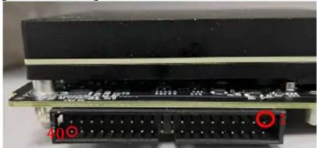
| Sysfs GPIO | Connector Label | Pin | Pin | Connector Label | Sysfs GPIO |
| 3.3 VDC | 1 | 2 | 5.0 VDC | ||
| /dev/i2c-7 | I2C_GP8_DAT | 3 | 4 | 5.0 VDC | |
| I2C_GP8_CLK | 5 | 6 | GND | ||
| gpio454 | MCLK05 | 7 | 8 | UART1_TX | /dev/ttyTHS0 |
| GND | 9 | 10 | UART1_RX | ||
| SFIO (gpio460) | UART1_RTS | 11 | 12 | I2S2_CLK | gpio398 |
| SFIO (gpio456) | PWM01 | 13 | 14 | GND | |
| gpio433 | GPIO27_PWM2 | 15 | 16 | GPIO8_AO_DMIC_IN_DAT | gpio325 |
| 3.3 VDC | 17 | 18 | GPIO35_PWM3 | gpio391 | |
| gpio483 | SPI1_MOSI | 19 | 20 | GND | |
| gpio482 | SPI1_MISO | 21 | 22 | GPIO17_40HEADER | gpio444 |
| gpio481 | SPI1_SCK | 23 | 24 | SPI1_CS0 | gpio484 |
| GND | 25 | 26 | SPI1_CS1 | gpio485 | |
| /dev/i2c-1 | I2C_GP2_DAT | 27 | 28 | I2C_GP2_CLK | /dev/i2c-1 |
| CAN0 | CAN0_RX | 29 | 30 | GND | |
| CAN0_TX | 31 | 32 | GPIO9_CAN1_GPIO0 | gpio324 | |
| gpio318 | CAN1_DOUT | 33 | 34 | GND | |
| gpio401 | I2S2_FS | 35 | 36 | UART1_CTS | SFIO (gpio461) |
| gpio319 | CAN1_DIN | 37 | 38 | I2S2_SDIN | gpio400 |
| GND | 39 | 40 | I2S2_SDOUT | gpio399 |
Note
None
2.12 Audio pin header
| Function | Audio pin header. |  | |||
| Location | J15 | ||||
| Type Description | HEADER_PIN_2*5(-8)PIN_2.54 mm_180°_SMD | ||||
| Manufacturer and Part Number | 頻銳 Pinrex212-92-05GBER | ||||
| Mating Connector | Any 2.54mm pitch standard interface female | ||||
| Pinout | Definition | PinNo. | PinNo. | Definition |  |
| MIC_L | 1 | 2 | GND | ||
| MIC_R | 3 | 4 | NC | ||
| Line Out (R) | 5 | 6 | NC | ||
| NC | 7 | 8 | (No Pin) | ||
| Line Out (L) | 9 | 10 | NC | ||
| Remarks | None | ||||
2.13 Gigabit Ethernet Connector
| Function | 1Gb single-port Ethernet connector, used to connect to the host system. | 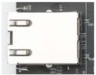 |
| Location | J16 | |
| Type Description | RJ45 with integrated magnetics | |
| Manufacturer and Part Number | 志展 Compupack(CPC)ACNRJGA0029-0061G-LEFT(G/Y)+RIGHT(Y)-UP | |
| Mating Connector | Any standard 1Gb Ethernet mating connector can be applicable. | |
| Pinout | Comply with Ethernet standards. | |
| Remarks | None | |
2.14 Micro SIM Card Socket
| Function | Micro SIM Card |  |
| Location | J17 | |
| Type Description | SOCKET_MICRO SIM_8PIN_90°_SMD | |
| Manufacturer and Part Number | 福軒 FullgloryFG-0271AAAG06APUSH PUSH 1.42H | |
| Pinout | Refer to Micro SIM card standard | |
| Remark | *Push Push type*Inserting directing as below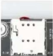  | |
2.15 Mini card socket
| Function | Mini Card (PCIe) interface |
| Location | J22 |
| Type Description | SOCKET_MINI PCIE_52PIN |
| Manufacturer and Part Number | FOXCONN, AS0B221-S68Q-7H_H=6.8MM-062AL6 |
| Mating Connector | Any Mini Card standard interface device. |
| Pinout | Please refer to Mini Card standard for the pinout details. |
| Remarks | None |
2.16 OOB board connector
| Function | Connector of OOB board |  | ||
| Location | J26, J27, J28 | |||
| Type Description | WAFER_1*2PIN_1 mm_180°_SMD | |||
| Manufacturer and Part Number | 宏致 ACES50228-00271-001_WTB | |||
| Mating Connector | 宏致 ACES50233-002H0H0-001 | |||
| Pinout | J26 | Description | ||
| PIN1 | +5V Power | |||
| PIN2 | GND | |||
| J27 | Description | |||
| PIN1 | Reset | |||
| PIN2 | GND | |||
| J28 | Description | |||
| PIN1 | Power | |||
| PIN2 | GND | |||
| Remarks | None | |||
2.17 54V DC POWER JACK
| Function | 54V Power input with lock | 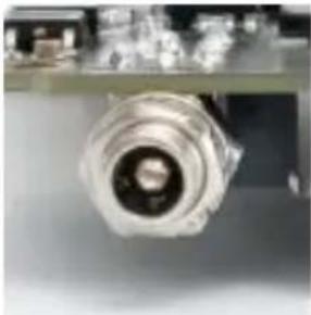 | ||
| Location | J30 | |||
| Type Description | JACK_DC POWER_D2.5 mm_90°_DIP include nut and washer | |||
| Manufacturer and Part Number | 京政 JKCR DCD-020-105B | |||
| Mating Connector | Any OD 5.5/2.5 mm & 12mm length plug | |||
| Pinout | Pin Number | Description | ||
| 3 | GND | |||
| 1 | Power | |||
| 2 | GND | |||
| Remarks | NA | |||
2.18 ATX 4P
| Function | ATX 4P |  | ||
| Location | J31 | |||
| Type Description | WAFER_2*2PIN_4.2 mm_90°_DIP | |||
| Manufacturer and Part Number | 福軒 FullgloryFPWD-42R2-04NAT | |||
| Mating Connector | power plug cable | |||
| Pinout | Pin Number | Description | ||
| 1 | GND | |||
| 2 | GND | |||
| 3 | 12-54V Power | |||
| 4 | 12-54V Power | |||
| Remarks | None | |||
2.19 USB 2.0 Gen 1 Type-A Connector #1, #2
| Function | USB 2.0 Gen 1 Type-A connector #1 #2 |  |
| Location | J33 | |
| Type Description | Dual-port USB 2.0 Gen 1 Type-A female connector | |
| Manufacturer and Part Number | 捷湧 EDLUAF208D010B | |
| Mating Connector | Any USB 2.0 standard Type-A interface cable or device. | |
| Pinout | Please refer to USB 2.0 Gen 1 standard. | |
| Remarks | None | |
2.20 12V power input connector for daughter board
| Function | 12V power input connector |  | |
| Location | J37 | ||
| Type Description | WAFER_1*5PIN_2 mm_180°_SMD | ||
| Manufacturer and Part Number | 宏致 ACES50310-0057N-001_WTB HEADER-H6.5mm | ||
| Mating Connector | 宏致 ACES50389-005H0H0-001 | ||
| Pinout | Pin Number | Description | |
| 1 | +12V Power | ||
| 2 | +12V Power | ||
| 3 | GND | ||
| 4 | GND | ||
| 5 | NC | ||
| Remarks | None | ||
2.21 PCIE x16 socket
| Function | PCIE x16 socket |  |
| Location | J5,J6 | |
| Type Description | SOCKET_PCIE_164PIN_180°_SMD | |
| Manufacturer and Part Number | 鴻海 Foxconn2EF5823-DA9D0-8F | |
| Mating Connector | Please refer to PCIE card standard | |
| Pinout | Please refer to PCIE card standard | |
| Remarks | None | |
2.22 Board to board connector (to Camera board)
| Function | Board to board connector |  | |
| Location | J60 | ||
| Type Description | WAFER_2*60PIN_0.5 mm_180°_SMD | ||
| Manufacturer and Part Number | SAMTECQSH-060-01-L-D-A-K-TRBTB-RECEPTACLE | ||
| Mating Connector | SAMTECQTH-060-03-H-A-D BTB-PLUGQTH-060-04-H-A-D BTB-PLUG | ||
| Pinout | Comply with Nvidia Devkit pinout. | ||
| Remarks | None | ||
2.23 CAN Bus 3-pin terminal block with transceiver
| Function | CAN Bus 3-pin terminal block with transceiver |  |
| Location | BJ3 | |
| Type Description | TERMINAL BLOCK_1*3PIN | |
| Manufacturer and Part Number | 進聯 DECA,ME030-38103T, GREEN-P3.81 mm | |
| Mating Connector | 進聯 DECA,MC420-38103Z |
| Pinout | Pin # | Description | |||
| 1 | CANH | ||||
| 2 | GND | ||||
| 3 | CANL | ||||
| Remarks | None | ||||
2.24 Debug port
| Function | Debug port | 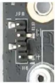 | ||
| Location | JP8 | |||
| Type Description | HEADER_PIN_1*4PIN_2.54 mm_180°_SMD | |||
| Manufacturer and Part Number | 宏致 ACES60240-00471-001 | |||
| Mating Connector | Any 2.54mm pitch standard interface female | |||
| Pinout | Pin # | Description | ||
| 1 | +3.3V Power | |||
| 2 | RX | |||
| 3 | TX | |||
| 4 | GND | |||
| Remarks | None | |||
2.25 Switch Button
| Function | Switch Button |  | ||
| Location | SW1 | |||
| Type Description | 4 SPST DIP switch | |||
| Manufacturer and Part Number | 圜達 DIPTRONICS IN OFF-SWITCHING 0.025A/24VDC | |||
| Pinout | Pin # | Description | ||
| 1 | OFF=>Auto Power ON=>Button Power | |||
| 2 | OFF=>FAN PWM ON=>FAN Always | |||
| 3 | NC | |||
| 4 | OFF=>CAN W/O Terminal ON=>CAN W/ Terminal | |||
| Remark | NA | |||
2.26 Power & Recovery Button
| Function | Power & Recovery control button | 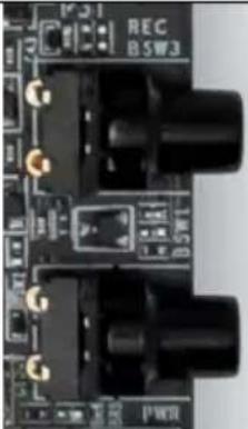 |
| Location | BSW1, BSW3 | |
| Type Description | Button | |
| Manufacturer and Part Number | 冠泰 ChampwayLS67AK-NBR-A-R2KA9RGB-CAP(BLACK) | |
| Pinout | N/A | |
| Remark | None | |
Other Switches and Jumpers
Other switches and jumpers listed on the boards but not mentioned in this manual are reserved for the internal use by AVerMedia. They are not open to the client application.
3.0 Installation
- Check and ensure all the external system power supplies are turned off.
● Install the Micro USB2.0 cable to Jetson platform connector. - Press and hold on the Recover button.
- Connect the power cord to the box PC.
3.1 BSP Setup Instructions
BSP (board support package) file: D315AO-R2.*.*.*.tar.gz for D315AO If you want to get the BSP download link, Please contact with AVerMedia FAE.
Default login username/password of the BSP is nvidia/nvidia
If you have difficulties to access the BSP download link, please visit AVerMedia website at https://www.avermedia.com/professional/download, or contact technical support at https://www.avermedia.com/professional/technical_support or e-mail us at eusupport@avermedia.com for further assistance.
BSP Installation steps for NVIDIA Jetson board: (Important Note: Please backup your personal files before re-flashing BSP)
After you download the BSP file and put the file in a Linux PC, please refer to the steps below to re-flash BSP.
1. Let the JETSON AGX Orin initiate recovery mode.
You have to keep pressing “Recovery” button and then power on the NVIDIA Jetson board to initiate recovery mode.
When connecting a NVIDIA Jetson board to a Linux PC via a MicroUSB to USB cable, you can check kernel messages with `dmesg` command in the Linux PC.
Once you see the similar messages as below, it means that the NVIDIA Jetson board is in the recovery mode.
[24685.229129] usb 1-7: Product: APX
[24685.229132] usb 1-7: Manufacturer: NVIDIA Corp
2. Using the commands below in the Linux PC to start re-flashing BSP.
# sudo is required to extract BSP
\$ sudo tar zxvf D315AO-R2.*.*.**.tar.gz
\$ cd JetPack_*.**/Linux_for_Tegra
\$ ./install.sh
4.0 Software
This section describes BSP's features for D315AO
- Support optional M.2 WI-FI/Bluetooth modules (Intel® Wireless-AX210), the manager UI of AX210 WiFi/Bluetooth is located on the upper-right corner of Ubuntu desktop. It can be also controlled by nmcli/bluetoothctl in command line.
- Power Mode
Power mode can be modified by the UI on the upper-right corner of Ubuntu or the following commands.
<h1 id="get-current-power-mode">get current power mode</h1>
$ sudo nvpmodel -q
<h1 id="setup-power-mode">setup power mode</h1>
<h1 id="where-x-is-power-mode-number-please-refer-to">where <x> is power mode number, please refer to</h1>
https://docs.nvidia.com/jetson/archives/r35.1/DeveloperGuide/text/SD/PlatformPowerAndPerformance/JetsonOrinNxSeriesAndJetsonAgxOrinSeries.html?highlight=nvpmodel#supported-modes-and-power-efficiency for more information
$ sudo nvpmodel -m <x>
* Current default power mode:
D315AO: MODE 30W (2)
- RTC Battery
The following command can get RTC battery voltage.
\$ sudo avt_tool -a | grep -oP "AIN5.*[\K[^]]*"
- Fan Speed
The following commands can get PWM fan information.
<h1 id="get-current-speed-setting-of-pwm-fan-0-255">get current speed setting of PWM Fan (0 ~ 255)</h1>
$ cat /sys/devices/platform/pwm-fan/hwmon/hwmon2/pwm1
<h1 id="get-fan-rpm-value">get Fan RPM value</h1>
$ cat /sys/devices/platform/39c0000.tachometer/hwmon/hwmon1/rpm
5. CAN Bus
(1) Enable and setup CAN Bus
<h1 id="1-enable-can-bus">1. Enable CAN Bus</h1>
$ sudo modprobe can
$ sudo modprobe can-raw
$ sudo modprobe mttcan

<h1 id="2-setup-can-bus">2. Setup CAN Bus</h1>
$ sudo ip link set can0 type can bitrate 500000 dbitrate 2000000 berr-reporting on fd on restart-ms 100
$ sudo ip link set can0 up
(2) Receive and Send
<h1 id="receive">Receive</h1>
$ candump can0
<h1 id="send">Send</h1>
$ cansend can0 <can_frame>
* where:
6. Camera
The camera support on D315AO are listing as below:
* ECON AR0230 (120p serdes camera)
Test Command:
> ECON eCAM20 (ar0230):
No width height framerate
0 640 480 60/45
1 960 540 58/30
2 1280 720 45
3 1280 960 34
4 1920 1080 30
\( gst-launch-1.0 -e v4l2src device=/dev/video0 do-timestamp=true ! 'video/x-raw,width=640,height=480,framerate=60/1,format=UYVY' ! fpsdisplaysink video-sink=ximagesink sync=false
\( gst-launch-1.0 -e v4l2src device=/dev/video0 do-timestamp=true ! 'video/x-raw,width=960,height=540,framerate=58/1,format=UYVY' ! fpsdisplaysink video-sink=ximagesink sync=false
\( gst-launch-1.0 -e v4l2src device=/dev/video0 do-timestamp=true ! 'video/x-raw,width=1280,height=720,framerate=45/1,format=UYVY' ! fpsdisplaysink video-sink=ximagesink sync=false
\( gst-launch-1.0 -e v4l2src device=/dev/video0 do-timestamp=true ! 'video/x-raw,width=1280,height=960,framerate=34/1,format=UYVY' ! fpsdisplaysink video-sink=ximagesink sync=false
\( gst-launch-1.0 -e v4l2src device=/dev/video0 do-timestamp=true ! 'video/x-raw,width=1920,height=1080,framerate=30/1,format=UYVY' ! fpsdisplaysink video-sink=ximagesink sync=false
7. GPIO usage
(1) Output: (e.g. gpio483)
sudo su
gpio_id=483
echo $gpio_id > /sys/class/gpio/export
cat /sys/kerne/debug/gpio | grep 483
gpio-483 (PZ.05)
$ gpio_index=PZ.05
echo out > /sys/class/gpio/$gpio_index/direction
echo 1 > /sys/class/gpio/$gpio_index /value # HIGH
echo 0 > /sys/class/gpio/$gpio_index /value # LOW
(2) Input
\$ sudo su
$ gpio_id=483
echogpio_id > /sys/class/gpio/export
$ cat /sys/kerne/debug/gpio | grep 483
gpio-483 (PZ.05)
$ gpio_index=PZ.05
echo in > /sys/class/gpio/gpio_index /direction
cat /sys/class/gpio/gpio_index /value # 1: HIGH, 0: LOW
(3) Disable
For L4T (Linux for Tegra) BSP support and the other software support associated with NVIDIA® Jetson AGX Orin, please visit AVerMedia website to contact our technical support function. (https://www.avermedia.com/tw/support/contact)
5.0 Force Recovery Mode
MicroUSB Jetson platform port of D315 can be used to re-program NVIDIA® Jetson AGX Orin by using the other host system running NVIDIA Jetpack, as the procedure described below.
-
Before you start
-
Please make sure to use a Linux host PC with Ubuntu 18.04 or 20.04 operating system.
- Please use a native setup (no virtual machine) installation file in the following steps.
● You will also need a high-quality standard USB. Type A to micro-USB cable -
Download installation file from Avermedia.
-
Connect carrier board to host PC
-
Connect the system to the Linux host PC. Please use a USB cable (micro-USB on the carrier board).
- After connecting to the host PC powering up the system. The system will detect the host PC and automatically enter the flashing state (also called force recovery mode).
- Check that the connection is established with the lsusb command. You should find one entry with Nvidia Corp. as highlighted below.
- Flashing of system
- Use the flash cmd script in the extracted bootloader folder to transfer the software into the Jetson compute module and flash it.
- Please connect a monitor to the system. After the flashing process has completed the should automatically boot and show the Ubuntu desktop.
● You now have a functioning system ready for your needs.
6.0 Accessory Drawings
6.1 Fan Module/ Adapter/ Power Cord
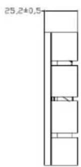
Fan Module for AGX Orin
■ Rated Voltage: 12V
■ Operating Voltage Range: 11.4V\~12.6V
■ Rated Speed: 4200±10% RPM
(Testing Speed After Continuous 3Minute Operation At Ambient Temperature Of 25°C)
■ Life Expectancy: 50,000 hours at 40°C (5 TO 90% RH)
■ Bearing Type: Two Ball


Power Adapter 041318GOUANL

64APOWERBRX-IPD (TW version)

AVerMedia

NVIDIA
ELITE PARTNER
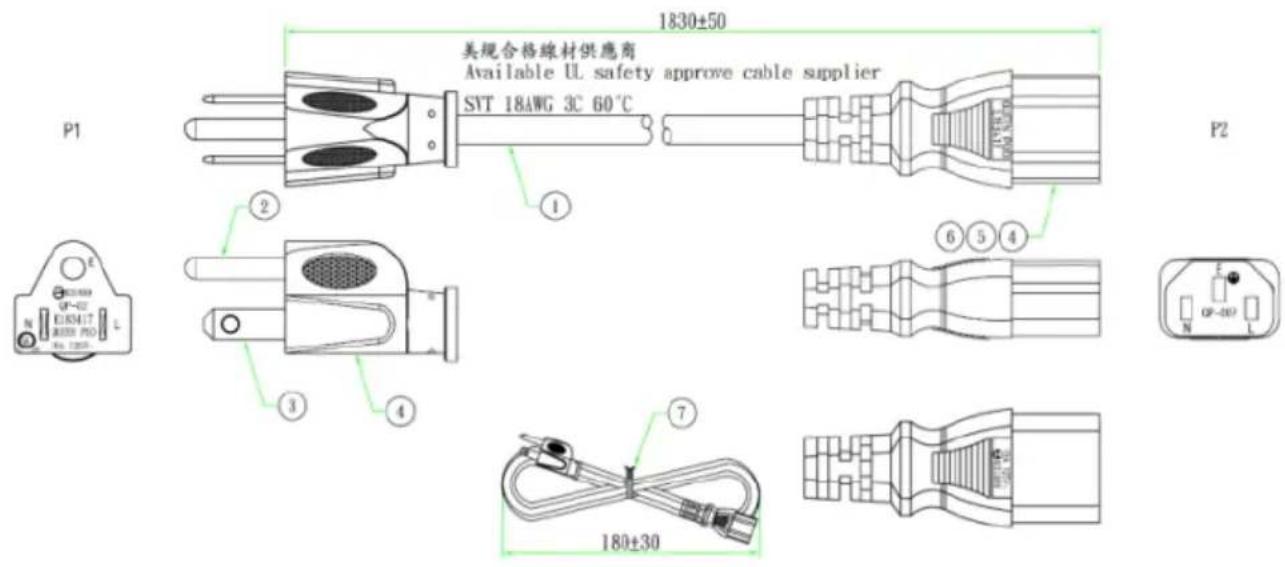
064APOWERBR2-IPD (US version)
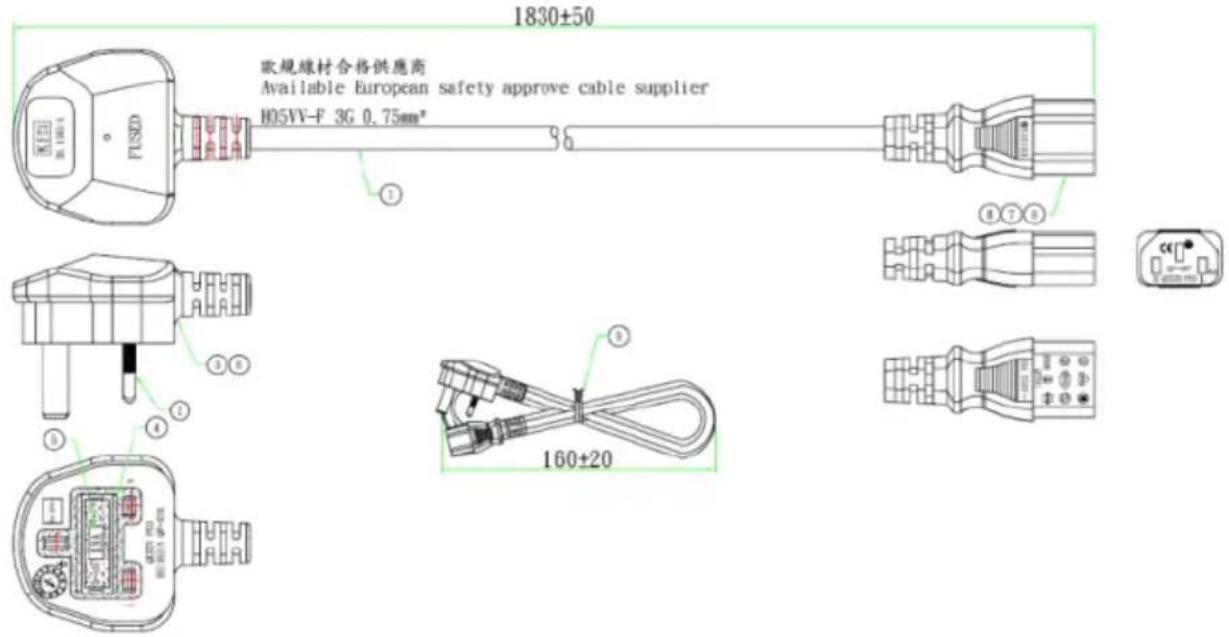
064APOWERBRW-IPD (UK version)
AVerMedia

NVIDIA
ELITE PARTNER
064APOWERBR5-IPD (EU version)

AVerMedia

NVIDIA
ELITE PARTNER
064APOWERBSL (JP version)
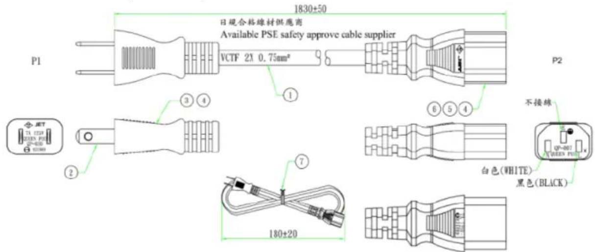
064APOWERBR4-IPD (CN version)

- AVERMEDIA D315 SERIES
- TABLE OF CONTENTS
- 1.0 INTRODUCTION......8
- 2.0 FEATURE DESCRIPTION.... 16
- AVERMEDIA
- PREFACE
- DISCLAIMER
- TECHNICAL SUPPORT
- CONTACT ENQUIRY
- DOWNLOAD USER MANUAL
- AVERMEDIA GLOBAL OFFICES
- HEADQUARTERS
- TAIWAN OFFICE
- THE AMERICAS
- USA OFFICE
- BRAZIL OFFICE
- LATIN AMERICA OFFICE
- EUROPE
- HEAD OFFICE EU
- RUSSIA OFFICE
- SPAIN OFFICE
- ASIA-PACIFIC
- CHINA OFFICE
- JAPAN OFFICE
- LIMITED PRODUCT WARRANTY
- COPYRIGHT NOTICE
- TRADEMARK ACKNOWLEDGEMENT
- ESD WARNING
- SAFETY PRECAUTION
- 1.0 INTRODUCTION
- 1.2 PRODUCT OVERVIEW
- BLOCK DIAGRAM
- 1.3 CONNECTOR SUMMARY
- 1.4 CARRIER BOARD INTERFACE
- 2.0 FEATURE DESCRIPTION
- 2.12 AUDIO PIN HEADER
- 2.13 GIGABIT ETHERNET CONNECTOR
- 2.24 DEBUG PORT
- 2.25 SWITCH BUTTON
- OTHER SWITCHES AND JUMPERS
- 3.0 INSTALLATION
- 3.1 BSP SETUP INSTRUCTIONS
- LET THE JETSON AGX ORIN INITIATE RECOVERY MODE
- USING THE COMMANDS BELOW IN THE LINUX PC TO START RE-FLASHING BSP
- SUDO IS REQUIRED TO EXTRACT BSP
- 4.0 SOFTWARE
- CAN BUS
- CAMERA
- GPIO USAGE
- 5.0 FORCE RECOVERY MODE
- 6.0 ACCESSORY DRAWINGS
- 6.1 FAN MODULE/ ADAPTER/ POWER CORD
- FAN MODULE FOR AGX ORIN
Brand : AVERMEDIA
Model : D315AOB
Category : Electronic board