
RGB Laser 1 6 - Laser projector MARTIN - Free user manual and instructions
Find the device manual for free RGB Laser 1 6 MARTIN in PDF.


| Product Type | RGB Laser Projector |
| Brand | Martin |
| Model | RGB Laser 1 6 |
| Category | Laser Projector |
| Laser Source | Diode-pumped solid-state (DPSS) laser |
| Laser Wavelengths | Red: 638 nm, Green: 520 nm, Blue: 445 nm |
| Output Power | 1.6 W (RGB combined) |
| Beam Angle | 45° x 45° |
| Control Options | DMX512, ILDA, Auto, Sound-active, Master/Slave |
| DMX Channels | 13 (or 7 in simplified mode) |
| Power Supply | AC 100-240 V, 50/60 Hz |
| Power Consumption | 150 W maximum |
| Dimensions (W x H x D) | 260 x 160 x 220 mm |
| Weight | 3.5 kg |
| Housing Material | Aluminum and steel |
| Cooling | Forced air convection (integrated fan) |
| Operating Temperature | 0°C to 40°C |
| Laser Safety Class | Class 4 (requires safety interlock) |
| IP Rating | IP20 (indoor use only) |
| Included Accessories | Power cord, DMX cable, safety cable, user manual |
| Maintenance | Clean optical windows with lens cleaning solution and microfiber cloth; check ventilation regularly |
| Reparability | Modules are replaceable; contact authorized Martin service centers |
| General Information | Professional-grade RGB laser projector for stage, disco, and architectural lighting effects |
Frequently Asked Questions - RGB Laser 1 6 MARTIN
User questions about RGB Laser 1 6 MARTIN
0 question about this device. Answer the ones you know or ask your own.
Ask a new question about this device
Download the instructions for your Laser projector in PDF format for free! Find your manual RGB Laser 1 6 - MARTIN and take your electronic device back in hand. On this page are published all the documents necessary for the use of your device. RGB Laser 1 6 by MARTIN.
USER MANUAL RGB Laser 1 6 MARTIN
RGB laser 1.6 TM user manual

Dimensions
All dimensions are given in millimeters
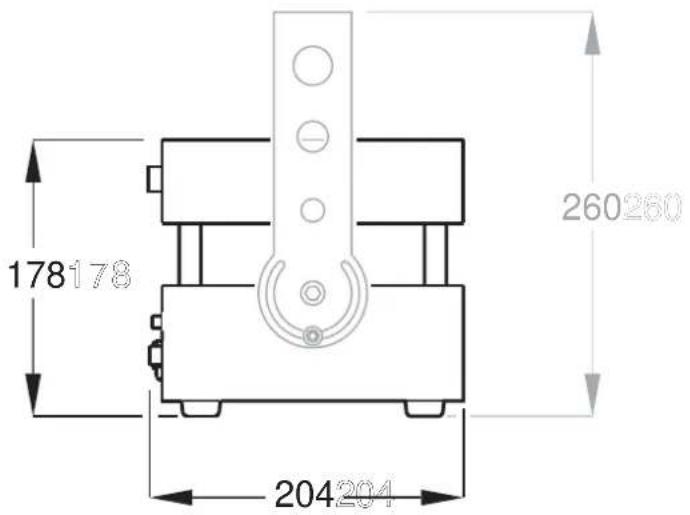

© 2006-2009 Martin Professional A/S. Information subject to change without notice. Martin Professional A/S and all affiliated companies disclaim liability for any injury, damage, direct or indirect loss, consequential or economic loss or any other loss occasioned by the use of, inability to use or reliance on the information contained in this manual. The Martin logo, the Martin name and all other trademarks in this document pertaining to services or products by Martin Professional A/S or its affiliates and subsidiaries are trademarks owned or licensed by Martin Professional A/S or its affiliates or subsidiaries.
P/N 35000189 Rev. C
Contents
Dimensions....2
Rear panels overview....4
Safety Information ....5
Introduction....7
Features 7
Special product information....8
Storage temperature 8
Temperature stabilization at power on 8
Internal memory 8
Installation 9
Connecting to AC power 9
Physical installation....9
Connecting to external devices....11
Operation....13
Monitoring fixture status....13
Using the control panel and display....14
Using the Martin RGB Laser Show Software....17
DMX operation....27
ILDA operation....28
Service and Troubleshooting....29
Cleaning 29
Replacing fuses....29
Firmware updates ....29
Martin RGB Laser 1.6 Specifications ....30
Appendix 1: DMX Protocol ....35
Appendix 2: Warning Label Location and Identification....36
Rear panels overview


N
A – Interlock safety cutout connector
B - USB signal indicator
C – DMX signal indicator
D - DMX out
E - DMX in
F - 6-pin XLR connector for link to PC via USB adapter cable
G - Display
H - ILDA in
I – Power input IEC connector
J - Control buttons
K - Keyswitch
L - ILDA out
M - Power on/off switch
N - Main fuseholder
Safety Information

DANGER! CLASS 4 LASER PRODUCT
General
DANGER! This product is for professional use only! It presents risks of lethal or severe injury due to laser radiation, fire and heat, electric shock, skin hazards and falls.
Read this manual before installing or powering the fixture, follow the safety precautions listed below and observe all warnings in this manual and on the fixture. If you have any questions about how to operate the fixture safely, please contact your Martin supplier or call the Martin 24-hour service hotline.
Refer all service not described in this manual to a Martin service technician.
Laser safety
This product is a Class 4 laser with more than 1000 mW visible output. This laser system presents a hazard from direct or specular reflections, but may also produce hazardous diffuse reflections and may present significant eye and skin hazards as well as fire hazards.
Warning! Only Laser Safety Officers who are officially certified by a regulatory body or authorized training organization are allowed to use class 4 lasers in public. The Laser Safety Officer is responsible for all aspects of use of this laser, including ensuring that all locally applicable safety laws and regulations are observed.
Laser Safety is regulated by different authorities in each country:
• In Canada, the Radiation Protection Bureau (RPB)
• In the United States of America, the Center for Devices and Radiological Health [CDRH]
• In Europe, the European Norm-organization CENELEC
Refer to these institutions for detailed information about the safety regulations that apply in your country before operating this laser. Note that if safety practices required by locally applicable law or regulations differ from those outlined in this manual, the stricter requirement must be respected.
Caution – use of controls or adjustments or performance of procedures other than those specified herein may result in hazardous radiation exposure.
Protecting yourself and others from electric shock and injury
- Disconnect the fixture from AC power before removing or installing a fuse or any part, and when not in use.
• Always ground (earth) the fixture electrically. - Use only a source of AC power that complies with local building and electrical codes and has both overload and ground-fault (earth fault) protection.
-
Do not expose the fixture to rain or moisture.
-
Do not use the fixture if ambient temperature is above 40° C ( 104° F) or below 5° C ( 41° F), if relative humidity exceeds 90%, or if condensation is forming.
- If the fixture, power cable or power plug is visibly damaged in any way, cut power, disconnect it and do not operate it until it has been repaired by Martin Service.
- Use only the power cable supplied with the fixture. Replacement power cables are available from Martin.
- If the output window is not in perfect condition, for example if there are visible cracks or scratches, disconnect the fixture from power and do not operate it until the output window has been replaced by Martin Service.
- Do not operate the fixture if any covers are open, missing or damaged in any way.
- Protect your eyes with laser safety goggles that give protection from the laser output as defined in the Specifications section of this user manual when working on or near the fixture.
- Do not look directly into the output window or laser beam.
- Keep fingers and objects out of the holes in the mounting bracket, as there is a risk of cutting or shearing if the fixture moves or is adjusted in the bracket.
- Keep fingers and other objects out of the cooling fans.
Protecting yourself and others from burns and fire
- Ensure that people and objects cannot come closer than 2 meters (7 feet) to the fixture within a zone of 80° × 80° around the output window.
- Keep the fixture well out of reach of the public.
- Keep the output window minimum 3 meters (10 feet) above the level of any floor that is accessible to the public.
- Do not illuminate any surface within 2 meters (7 feet) of the fixture
- Keep combustible materials (for example fabric, wood, paper) at least 1 meter (40 inches) away from the fixture.
- Keep flammable materials well away from the fixture.
- Maintain a minimum free space of 30 centimeters (12 inches) around the fixture.
- Do not attempt to bypass thermal protection mechanisms or fuses.
- Replace defective fuses with ones of the specified type and rating only.
Protecting yourself and others from injury due to falls
- When suspending the fixture above ground level, check that the structure can hold at least 10 times the weight of all installed devices.
- Check that all external covers and rigging hardware are securely fastened and use an approved means of secondary attachment such as a safety cable.
- Block access below the work area whenever installing, servicing or removing the fixture.

Martin products are supplied in compliance with Directive 2002/96/EC of the European Parliament and of the Council of the European Union on WEEE (Waste Electrical and Electronic Equipment), as amended by Directive 2003/108/EC, where applicable.
Help preserve the environment! Ensure that this product is recycled at the end of its life. Your supplier can give details of local arrangements for the disposal of Martin products
Introduction
Thank you for selecting the Martin RGB Laser 1.6 ™ . This laser fixture is designed to give full access to laser light effects and projections using a regular lighting desk with DMX output or an advanced laser controller.
The RGB Laser 1.6 is supplied with a library of standard beam and graphic effects stored in internal memory and controllable by DMX. A PC software package supplied with the fixture allows effects to be taken from a library or created, edited and stored in internal memory. Effects editing is intuitive and user-friendly, with parameters, image and text editing in a familiar Windows environment. Effects can be projected in real time by the RGB Laser 1.6 while they are edited.
The RGB Laser 1.6 also has a standard ILDA analog connection, and can be controlled using any ILDA-compatible laser control device.
A range of fail-safe systems shut down the laser if the operator attempts to project a beam that is static and concentrated enough to cause injury.
Features
- Direct RGB color mixing through analog modulation
- White-light laser with balanced cool white
- Adjustable white balance
- Onboard show playback system with 432 cues available
- Library of 288 cues supplied pre-installed
• Real-time effect programming, editing and viewing - USB 2.0 PC interface
- DMX controllable
- Stand-alone demo mode with 256 cues available
- Stand-alone (autostart) mode
- Can be operated with any ILDA compatible controller
- Fail-safe laser radiation protection systems
• Temperature stabilized - Dust-free sealed optics
- Rugged, compact design
• Auto-sensing power supply: 100-240 VAC, 50/60Hz - Wide ambient temperature range from 5°C (41°F) non-condensing to 40°C (104°F)
- Rated diode life of 10 000 hours (at 80% output), giving minimal service cost and downtime
Special product information
Storage temperature
Diode laser devices are subject to internal thermal stresses that have a small effect on beam precision over time if the device is exposed to temperature fluctuation. The effect on precision is minimal: after 100 cycles of being warmed from 5°C (41°F) up to 40°C (104°F) and back again, RGB beam drift will be less than 1% of beam diameter. However, for maximum beam precision over the RGB Laser 1.6's lifetime, store the fixture at room temperature and keep ambient temperature as stable as possible.
Temperature stabilization at power on
Important! When power is applied, laser output may be disabled for between 1 and 10 minutes while diode temperature stabilizes.
When the RGB Laser 1.6 fixture is powered on, laser output is disabled and the message Warming up appears in the display until the laser operating temperature has stabilized:
- At room temperature of 20-25°C (68-77°F), stabilization takes approximately one minute.
- At the two extremes of the ambient temperature range the fixture can operate in, i.e. at 40° C ( 104° F) or 5° C ( 41° F), stabilization takes approximately 10 minutes.
Maximum diode lifetime is obtained if the laser is only used at stabilized operating temperature. We therefore recommend you wait for minimum one minute after powering on before you activate the beam.
Internal memory
The RGB Laser 1.6 has 128 MB of internal flash memory available for storing cues and settings. It is supplied with 288 cues stored in memory. Cues can be uploaded to memory using a PC running the supplied Martin Laser Show software and connected to the RGB Laser 1.6 using the supplied USB to 6-pin XLR adapter cable.
The internal memory uses a special file system and is supplied correctly formatted. The memory can be reformatted using Tools → Format card... in the Martin Laser Show software, but reformatting should only be carried out if the show software reports that there is a memory error while uploading cues.
Instructions for projecting and uploading cues are provided in the Operation section of this manual.
Installation
Warning! Read 'Safety Information' on page 5 before installing the Martin RGB Laser 1.6.
Connecting to AC power
Warning! Local AC power must have both overload and ground fault (earth leakage) protection.
The RGB laser 1.6 power supply is fully auto-sensing and the fixture can be connected to AC power at any nominal voltage from 100 - 240 VAC at 50 or 60 Hz.
Installing a power plug
Warning! For protection from dangerous electric shock, the fixture must be grounded (earthed). Consult a qualified electrician if you have any doubts about proper installation.
The RGB Laser 1.6 is supplied with three IEC-type power cables: one with a Schuko (Euro) plug, one with a US plug, and one with no plug.
If neither of the first two power cables matches your local power outlets, fit the third cable with a suitable grounding-type (earthed) power plug, following the plug manufacturer's instructions. Connect the yellow and green wire to ground (earth), the brown wire to live, and the blue wire to neutral. The table below shows some pin identification schemes.
| Wire | Pin | Marking | Screw |
| brown live “L” yellow or brass | |||
| blue neutral | “N” silver | ||
| yellow/green | ground | green | |
color
Physical installation
The RGB laser 1.6 may be suspended at any angle from a suitable support such as a truss, placed on a horizontal surface resting on its rubber feet, or fastened to a surface.
DANGER! Ensure that people and objects cannot come closer than 2 meters (7 feet) to the fixture within a zone of 80° × 80° around the output window.
The RGB laser 1.6 must be positioned well out of reach of the public. The output window must be kept minimum 3 meters (10 feet) above the level of any floor that is accessible to the public.
Do not illuminate any surface within 2 meters (7 feet) of the fixture. Locate the fixture at least 1 meter (4 feet) from any combustible materials (wood, fabric, paper, etc.) and well away from any flammable materials. Leave 30 centimeters (12 inches) minimum free space around the fixture.
Suspending from a support
Warning! Block access below the work area and work from a stable platform when installing, servicing or removing the machine.
Use a secure secondary attachment such as a safety wire that can hold at least 10 times the weight of the machine.
Keep fingers and other objects out of the holes in the mounting brackets.
Rigging clamps, omega brackets, fasteners and safety wires are available as accessories from your Martin supplier.
To suspend the fixture from a support:
- Ensure that any structure used to support the machine can support at least 10 times the total weight of all installed fixtures, clamps, cables, auxiliary equipment, etc.
- Ensure that all rigging clamps and fasteners are undamaged and can support at least 10 times the machine's weight.
-
Bolt a rigging clamp to the fixture's flying bracket using a grade 8.8 (minimum) M12 bolt and lock nut, or as recommended by the clamp manufacturer, through the 13 mm hole in the center of the mounting bracket.
-
Loop a safety wire that can hold at least 10 times the weight of the machine through/over the support and around one of the four corner pillars that connect the fixture's upper and lower modules. Do not simply loop the safety wire around the flying bracket, as this will leave the fixture unsecured.
-
See illustration on right. Keep fingers and other objects out of the holes in the mounting bracket. Loosen the swivel lock Allen screws approximately one full turn, tilt the fixture to the desired angle and retighten the screws.
-
Ensure that fixture, rigging hardware and safety attachment are secure and that the output window is minimum 3 meters (10 ft.) above any publicly accessible floor before applying power.

Placing on a horizontal surface
The RGB laser 1.6 can be placed or permanently installed on a level horizontal surface resting on its rubber feet.
To install the fixture on a horizontal surface:
- Ensure that the surface is level, stable and capable of supporting at least ten times the weight of the machine.
- Secure the machine so that it cannot slide, fall, or tilt, even if vibration from audio equipment or another source is present.
- Eliminate any risk of loss of alignment or contact by members of the public.
Connecting to a PC
The RGB Laser 1.6 can be connected to a PC running the Martin RGB Laser Show software via the 6-pin XLR socket on the upper rear panel. Use the 6-pin XLR to USB adapter cable supplied with the fixture.
Note how connecting to a PC affects demo mode:
- If a PC is connected first and the RGB Laser 1.6 is then powered on, demo mode will be disabled until the fixture is powered off and then on again with no PC connected.
- If a PC is connected after the RGB Laser 1.6 has been powered on, demo mode will be disabled until the PC is disconnected again – in this case there is no need to power the fixture off and on to enable demo mode.
Connecting to a DMX data link
The RGB Laser 1.6 DMX data connections are XLR type, wired with pin 1 to ground, pin 2 to signal - (cold), and pin 3 to signal + (hot). This is the standard configuration for DMX devices.
To connect to the DMX data link:
- Power all devices off.
- Run a data cable from the DMX output of the DMX controller or the previous fixture on the data link to the RGB Laser 1.6's DMX IN socket
- Either:
- run a data cable from the DMX OUT socket of the RGB Laser 1.6 to the IN socket of the next fixture, or
- terminate the DMX link by inserting a 5-pin XLR male termination plug into the data output of the last fixture. A termination plug is simply an XLR connector with a 120 Ohm, 0.25 W resistor soldered across pins 2 and 3.
Connecting to an ILDA analog control device
The RGB laser 1.6 has a symmetrical ILDA standard 25-pin Sub-D input connector and a 1:1 wired 25-pin Sub-D output (throughput) connector for connection to an ILDA control link.
ILDA analog Sub-D connector pinout
The pinout and maximum voltages for the ILDA standard Sub-D connectors are as follows:
| Pin | Signal |
| 1 | X + (horizontal) + 5.0 V |
| 2 | Y + (vertical) + 5.0 V |
| 4 | Interlock A |
| 5 | Red + + 2.5 V |
| 6 | Green + + 2.5 V |
| 7 | Blue + + 2.5 V |
| 13 | Shutter + 5.0 V |
| 14 | X - (horizontal) - 5.0 V |
| 15 | Y - (vertical) - 5.0 V |
| 17 | Interlock B |
| 18 | Red - - 2.5 V |
| 19 | Green - - 2.5 V |
| 20 | Blue - - 2.5 V |
| 25 | Ground |
Operation
DANGER! Read 'Safety Information' on page 5 before operating the Martin RGB Laser 1.6.
Only Laser Safety Officers who are officially certified by a regulatory body or authorized training organization are allowed to use the Martin RGB Laser 1.6. The Laser Safety Officer is responsible for all aspects of use of this laser, including ensuring that all locally applicable safety laws and regulations are observed. The security key for the key switch must stay with the Laser Safety Officer at all times.
Before powering on or operating the RGB Laser 1.6, make sure that there will be no risk from sudden exposure.
Do not allow people or objects to come within 2 meters (6.5 feet) of the RGB Laser 1.6 in the 80° horizontal, 80° vertical projection zone in front of the output window while the fixture is connected to power.
Protect your eyes with laser safety goggles that are suitable for the RGB Laser 1.6 emissions listed in the specifications section of this manual when working on or near the fixture, unless you have made sure that the fixture is powered off and that power cannot be reapplied. Do not look directly into the output window or laser beam.
Use of controls or adjustments or performance of procedures other than those specified in this user manual may result in hazardous radiation exposure.
Important! Lasers are sensitive to temperature conditions. Do not operate the RGB Laser 1.6 at ambient temperatures below 5°C (41°F) or above 40°C (104°F), or you will cause damage to the diodes that is not covered by the product guarantee.
Note that the heatsink between upper and lower modules can reach up to 55° C ( 131° F) when operating at close to the upper ambient temperature limit.
Monitoring fixture status
DANGER! See illustration on right. When the EMISSION LASER ON LED is lit, the laser is enabled and can project a beam without any other warning.
The RGB Laser 1.6 has two feedback LEDs and a backlit LCD display that allow you to monitor the status of the fixture:
- The EMISSION LASER ON LED lights when the laser is enabled, whether it is projecting a beam or not. It is an important safety indicator.
- The DMX and USB LEDs on the lower rear panel light when the fixture is receiving valid DMX data or there is a USB connection to a PC respectively.

Status messages in the display
When you power the fixture on at the main power switch, the fixture's current status appears in the display:
| Status message Is displayed when... | |
| Laser of f | ...the keyswitch is in the OFF position, the interlock is open, or the housing is open |
| Ext er nal ILDA | ...the keyswitch is in the External position and the fixture will respond to ILDA control signal input via the ILDA connector |
| Int er nal DMX: XXX | ...the keyswitch is in the DMX position, and the fixture is using its internal controller. The fixture will communicate with a PC running the Martin Laser Show software and accept DMX control signal input via the DMX connector (XXX is the fixture's DMX address) |
Each time the keyswitch is turned to a new position, the display shows the new status.
If the interlock or the housing is open, the display shows Laser off regardless of keyswitch position.
Using the control panel and display
The RGB Laser 1.6's onboard control panel and backlit LCD display allow you to read fixture status data, adjust settings and set the fixture's DMX address.
Control panel
The buttons grouped together on the control panel have the following functions:
The + and - (plus and minus) buttons scroll through the main menu.
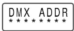
Main menu items are underlined with a line of stars *
Once you have scrolled to the main menu item that you want to adjust, the ▲ and ▼ (up and down) buttons scroll through the submenus.
Once you are in a submenu, the + and - buttons adjust values in the submenus. These buttons have no effect in the Info menu because there are no values to adjust.
The ENTER button in the center is used to start and stop selected cues in Demo mode and to reset values in the Settings menu.

Control menus
The table below gives an overview of the menus, submenus and functions or values in the control panel.
| Main menu Submenu Function/values | ||
| DMX ADDR********** | 0 - 508 | |
| Info********** | Soft ware | Current fixture software version. |
| Temp. ¿C | Baseplate temperature. | |
| Temp. ¿F | Baseplate temperature (degrees Fahrenheit). | |
| Total Hrs. | Total hours of fixture operation. | |
| LD Hrs. | Total hours of operation of the laser diodes. | |
| Power R | Average power output in mW of red laser. | |
| Power G | Average power output in mW of green laser. | |
| Power B | Average power output in mW of blue laser. | |
| Settings********** | Size X | Horizontal size and orientation (flip): from -512 to +512Default = +512 (100%). |
| Size Y | Vertical size and orientation (flip): from -512 to +512Default = +512 (100%). | |
| Offset X | Horizontal position: from -512 to +512Default = 0 (center position). | |
| Offset Y | Vertical position: from -512 to +512Default = 0 (center position). | |
| Gain R | Red laser gain 0 – 100%: 0 – 255Default = 255 (100%). | |
| Gain G | Green laser gain 0 – 100%: 0 – 255Default = 255 (100%). | |
| Gain B | Blue laser gain 0 – 100%: 0 – 255Default = 255 (100%). | |
| Enter to reset! | Press ENTER to set all the values in the Settings menu to default values. | |
| Demo********** | Enter to start XX | Press ENTER to start the selected cue. |
| Enter to stop XX | Press ENTER to stop the cue that is currently running. | |
| ïi. Page: XX | Select page 1 – 8 from the pages of cues stored in fixture memory (top line of display shows status message: see next page). | |
| ïi.. Cue: XX | Select cue 1 – 32 from the currently selected page of cues (top line of display shows status message: see next page). | |
The following status messages are displayed in the top line of the display in demo mode:
| Message Indicates that ... | |
| IDLE...... | ...the fixture is ready. |
| PLAY...... | ...a cue is already running. |
| BUSY...... | ...the fixture is receiving signals from a PC running Martin Laser Show software or from a DMX controller (demo mode will become available again as soon as the PC or the DMX controller is disconnected or powered off). |
| DISABLED...... | ...either the fixture detected a connection to a PC at power on (demo mode is disabled until the PC is powered off and on again with no PC connected), ...or stand-alone autostart mode has been activated in the Martin Laser Show software (demo mode is disabled until stand-alone autostart mode is de-activated in the Laser Show software). |
| ERROR...... | ...the internal memory is corrupt or incorrectly formatted |
Fixture information readouts
The Inf o menu in the control panel has the following submenus:
- Soft ware: Displays fixture's internal firmware version.
- Temp. C : Internal baseplate temperature. In normal conditions, this should stay between 24°C and 28°C. If it falls below 15°C or rises above 30°C, the ambient temperature may be outside the specified limits. If you do not bring the ambient temperature back to within the limits, the laser may shut down. Displays ↑ while the fixture is warming up, ↓ while the fixture is cooling down and * when stable optimum temperature is reached.
• Temp. ¿F: Identical to above but in degrees Fahrenheit. - Total Hrs. and LD Hrs.: Display the total number of hours of fixture operation and the number of hours with laser diodes active since manufacture. These counters are not user-resettable.
- Power R, Power G, Power B: Display power readings for red, green and blue laser diodes, measured at the sources inside the fixture and averaged over several samples while the laser is modulated..
Fixture settings and manual adjustment
As well as the adjustments available in the show software (see 'Live control during playback' on page 26), fixture settings can be adjusted using the Settings menu in the control panel.
Adjusting offset and size for the x and y axes allows you to define your projection area and keep it within safe limits. There are two advantages to setting your safe projection area manually in this way:
-
You no longer need to pay attention to the risk of projecting outside your safe projection area when controlling offset and size (zoom) via the control desk.
-
You have the full resolution of the DMX signal available to control offset and size (zoom) via the control desk.
The following settings are available:
- Size X and Size Y: Allow adjustment of the size of the projection. The default value is +512 (100%). At negative values the image is flipped (reversed left-to-right or inverted). Negative value -512 gives a full-size flipped image. Flipping the image can be useful if the laser is being used with a mirror or for back projection, for example. When using two fixtures, you can obtain symmetrical effects by flipping the x axis on one fixture.
- Offset X and Offset Y: Move the projection without affecting projection size. You can use these controls to adjust the position of the projection to illuminate a specific area or avoid projecting into the public. The default value is 0 (center position, no offset).
- Gain R, Gain G, Gain B: Allow adjustment of color balance. The laser diode manufacturing process means that it is quite normal for output power of the three different colors to vary by up to ±2.5%. Because of this, color balance adjustment may be necessary if you are running more than one fixture and want to obtain the same white light color temperature from each fixture. The default value is +512 (100%).
- Enter to reset! As soon as this menu item is displayed, pressing the ENTER button in the center of the control panel resets all the functions in the Settings menu to their default values.
Demo mode
The RGB Laser 1.6's demo mode lets you run cues 1 – 32 from pages 1 – 8 of the fixture memory without an external controller and without setting the fixture to stand-alone mode in the Martin Laser Show software.
Demo mode is NOT available:
- if the fixture is receiving signals from a PC running the Martin Laser Show software
- if the fixture has been powered on with a PC connected (it must be powered off then on again with no PC connected before demo mode is available)
- if the fixture is receiving signals from a DMX controller
- if the fixture has been set up using the Martin Laser Show software so that it automatically plays a cue at start-up (see Stand-alone mode on page 25).
Using the Martin RGB Laser Show Software
The Martin RGB Laser Show software package is supplied with the product. The most recent version of the software can also be downloaded from the Support area of www.martin.com.
The Laser Show software allows you to
- Manage shows (save, backup, edit, transfer to storage media, etc.)
- Trigger cues by clicking on buttons with the mouse
- Upload frames or complete animations to the RGB Laser 1.6's internal memory
- Create and edit the frames and animations online (real time editing)
• Control several parameters live during cue playback
- Update the fixture firmware
- Select a cue to run in stand-alone (autostart) mode
If you use the show software online (i.e. with a Martin RGB Laser 1.6 connected and running), you can view edited cues in real time.
If you use the show software offline, certain functions – such as uploading – are disabled, but you can familiarize yourself with the software and prepare shows for upload at a later time.
Managing shows in workspaces
A workspace (*.sws) file contains all the elements of a laser show packaged into one single file. Workspace files offer a convenient way of storing, backing up and transferring laser shows.
You can create a new workspace or open and save an existing workspace using the File menu.
Previewing and triggering cues, selecting pages
When you start the show software, the main window appears:

There are 48 cue buttons on each page. Each cue button carries an image of the cue's projection on a black background. Empty cues simply carry the word Empty.
The RGB Laser 1.6 is supplied with cues stored on pages 1 – 6. Pages 7, 8 and 9 are empty and available for user-designed cues.
Click on any cue button that is not empty to preview or trigger that cue.
Pages are banks of cues. To change the active page, select one of the PAGE tabs 1 - 9 at the bottom of the window.
Creating, editing and importing frames and animations
To edit the content of a cue, select the cue and click on Edit in the toolbar (or right-click the cue and select Edit from the pop-up menu) to open the Edit window. In this window you can create, edit and import frames and animations. Select editing tools from the toolbar on the left.
Imported graphics will probably need to be processed and converted in suitable software such as 3D Studio MAX and Lasershow Converter MAX from Pangolin Laser Systems, for example.
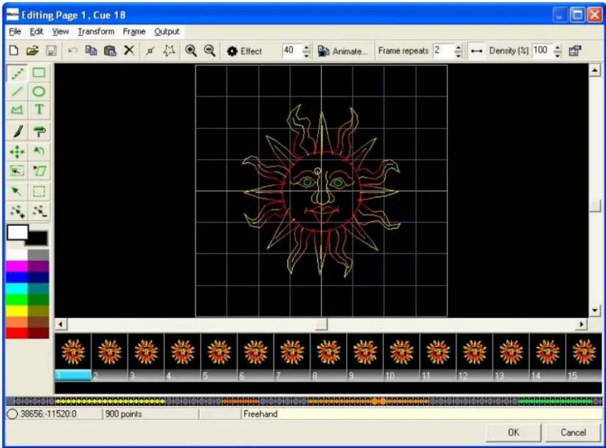
When you have finished editing, click on OK to return to the main window.
If you made any changes to the cue, you will notice that the cue button now has a floppy disk icon in the upper right corner. The icon is a reminder that the content of the cue has only been updated in the software and the fixture memory still contains old data. You can preview changes to cues while the floppy disk icon is displayed, but you need to carry out an upload in order to synchronize fixture memory with the software workspace.

To update internal memory with the changes, click on the Upload button on the toolbar or use one of the Upload options in the Tools menu.
Cue properties
To view or modify the properties of a cue, right-click on the cue button and select Properties... from the pop-up menu.
You can now view or modify a number of parameters for the cue, including:
- Settings (projection size, animation type and zone, autostart setting)
• Output (sample rate and custom color settings)
• Vector settings (for advanced users)
• Information about the cue and memory usage

Properties... → Settings
Size
Size X = Size X for this particular cue
Size Y = Size Y for this particular cue
Animation
Stop output at the end: The cue runs once and stops. If the cue only contains one frame, there will be one very short flash whenever this cue is executed. This setting is therefore mainly useful for multi-frame animations.
Loop animation: The cue runs in a loop and starts again automatically when it reached the end. It continues looping until another cue is selected.
Suspend on the last frame: The cue runs once and stops but holds the last frame of the animation.
Repeat last frame for duration, then terminate output: Similar to Suspend on the last frame, but you can set how long the last frame is held by scrolling to a value in the Last frame duration box. Possible times are 0.01 – 60 seconds.
Calculate duration: Clicking this box displays how long one frame takes to be projected. For example, if it shows 0.30 and you have a cue with 10 pictures in the animation, it will run for 3 seconds.
Options
Projection zone: You can choose between four projection zones: Graphics, Atmosphere, Beam Effects and User Defined. Choosing one of these projection zones for a cue applies the settings defined for that zone in Settings → Geometric correction... to the cue.
To exploit this feature, adjust your projection area in the Settings → Geometric Correction... menu:
• to match the projection surface or screen in Zone 1: Graphics
• to project in a safe area above the public in Zone 2: Atmosphere Effects
- to project to a specific area (for example, an area where effect mirrors are placed) in Zone 3: Targeted Beams
• to project to any other area you may wish to create in Zone 4: User defined.
Then choose which of these zones you want your cue to be projected in.
Checkbox: Automatically play this cue after power up of FB3SE board: Use this checkbox to set up stand-alone (autostart) mode. If you check this checkbox for a cue, the cue will start automatically
after you apply power to the RGB laser if the keyswitch is set to DMX internal.
If you have selected a cue to be played automatically after power up, a colored star appears in the cue's preview window (see illustration on right).
If you have linked cues in a loop, cues will play repeatedly after power up.
To select a different cue to start automatically at power up, check this checkbox in the new cue's Properties... window. The old cue will automatically be deselected.

Properties... → Output
Sample rate
Scan rate: You can adjust the scan frequency for a cue by entering its scan rate as a percentage of the master scan rate setting (the master scan rate setting is defined in Settings → Projector settings → Master scan rate). Possible values are 25% - 200%
Sample rate: You can adjust the scan frequency for a cue independently of the master setting by entering its sample rate. Possible values are 5 – 30 K-PPS (kilopoints per second).
Overwrite projector color channels settings for this cue
If you check the Overwrite projector color channels settings for this cue checkbox, you can adjust the color for this cue independently of the master color settings (the master color settings are defined in Settings → Projector Settings → Master scan rate and Color settings). Red, green and blue intensity can be adjusted from 0% to 100%.
Properties... → Vector settings
If you check the Overwrite projector Vector display settings for this cue checkbox, you can adjust the vector settings for this cue independently of the master vector setting (the master vector setting is defined in Settings → Projector Settings → Vector display settings).
The vector settings options available for individual cues are the same as the master vector settings options, and are explained under "Projector settings... → Vector display settings" on page 23.
Properties... → Information
This window displays information about the cue and memory usage.
Cue information shows the date the cue was last modified and the cue's internal ID number.
If the laser is connected, Memory information shows the amount of memory used by the cue, total memory capacity and how much memory capacity is still available.
Settings menu
The Settings menu contains two submenus:
- Projector settings
- Geometrical correction
Projector settings
Projector settings are master settings that are applied to all cues (except cues that have been given their own custom settings in the Properties... window).
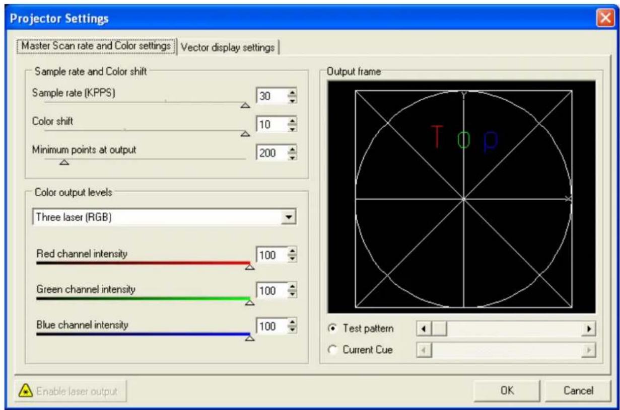
Before adjusting the projector settings, you may find it useful to read the following explanation of some of the principles involved.
Due to the mechanical behavior of the projection galvos, the length of and number of points in a projected line affect the projected image's characteristics.
A projected image is mapped as vector points to force the galvos to go to that point at maximum speed. Effective speed depends on how many points are in a line. The more points a line has, the more precise the projection, but the more it flickers.
The image map of a square only contains the square's four corner points. Because of galvo inertia, raw projected output will have a tendency to be circular rather than rectangular. The software can counteract this tendency in two ways: firstly it can add points on the straight lines and secondly it can detect the angle, note that the laser beam has to make a sharp change in direction, and add more points to the four corner points to give the galvos enough time to change direction.
If you have two objects to project, the projection will follow a connection line between these two objects, but with the laser dimmed to 0%. This is called a blank line.
Projector settings... → Master Scan rate and Color settings
Sample rate and color shift
Sample rate (K-PPS): Sets the master scan speed in kilopoints per second. Possible values are 5 – 30.
Color shift: Delays color modulation in relation to scanning. Modulation is faster than scanning, so it has to be delayed and adjusted to match galvo movement. When color shift is correctly adjusted, the color at the beginning and at the end of a scanned line will be the same. Possible values are 0 - 10.
Minimum points at output: Sets the minimum number of points the projector will use when displaying an image. Blankpoints are added to an image if it contains fewer points than this minimum, in order to keep the projection stable and avoid safety override by the scanner. Possible values are 8 – 2000.
The more illuminated points a projected image contains, the brighter it will be. Blankpoints added to an image are not illuminated and will reduce brightness. Therefore:
- If you have a small image that is made up of fewer points, it can be an advantage to set a lower value for Minimum points at output. This will reduce the number of blankpoints added and increase image brightness. However, if the image becomes too intense, the scanner will override and cut output for safety reasons.
- If you have several separate objects, it can be advantageous to enter a higher value to harmonize the brightness of each object.
Color output levels
Allows you to set laser type and adjust red green and blue channel intensity master settings for white balance.
For the Martin RGB Laser 1.6, do not change the default laser type setting, i.e. Three laser (RGB).
Projector settings... → Vector display settings
Spacing
Visible lines spacing: The maximum allowed distance between two points in all visible lines. If the distance between two points in an image exceeds the figure set here, the software will automatically add points between these two points to make the projection more stable.
- If you increase this value, fewer points will be added. The result is increased scanning speed but reduced precision and image quality.
- If you decrease this value, more points will be added. The result is higher projection quality but reduced scanning speed.
Blanked lines spacing: The maximum allowed distance between two points in all invisible lines. If the distance between two points in a blank line exceeds the figure set here, the software will automatically add points between these two points to make the projection more stable.
- If you increase this value, fewer points will be added to the blank line. The result is increased scanning speed, but the start point of the next visible line might not be precise and you may see a tail fading in.
- If you decrease this value, more points will be added. The result is higher projection quality but reduced scanning speed.
Anchors and Angle optimization
Visible Line begin: When a visible line begins, there will be one point to project. To force the galvos to start at this point more precisely, you can overlay more points at the beginning of a visible line.
- If you increase this value, the line starts more precisely at the expected co-ordinates, but also will become brighter because the laser stays at this point longer than at just one point. The point then becomes a hotspot.
- If you decrease this value, the laser may start projecting before the galvos reach the correct coordinates.
Visible Line end: When a visible line ends, there will be one point to project at the end. To force the galvos to reach the end of the line more precisely you can overlay more points at the end of the visible line.
- If you increase this value, the line ends more precisely at the expected co-ordinates, but also will be brighter at this point.
- If you decrease this value, the laser may stop projecting before the galvos reach the correct coordinates and a fade out tail may be seen at the end of the line.
Visible Corner: If the software detects a sharp angle, it will add/overlay more points at this set of coordinates. You can adjust how many points are added here.
• If you increase this value, more points will be added and the corner will be sharper.
• If you decrease this value, fewer points will be added and the corner will be more rounded.
Linear angle to anchor relation: Sets the threshold for when an angle is detected as a sharp angle and the software starts to add points.
Blanked Line begin: Same as Visible line begin, but for blank lines.
Blanked Line end: Same as Visible line end, but for blank lines.
Test pattern: This fader lets you choose from a range of standard test patterns to make it easier to adjust the vector display settings.
Current Cue: This fader displays the currently selected cue so that you can make adjustments while watching the cue.
Geometrical Correction
The geometrical correction options in the Settings menu allow you to modify image geometry. They are useful for setting the limits of projection zones and matching images to the characteristics of the projection surface (compensating for keystoning, for example).
You can define geometrical settings for each of the projection zones that you can route cues to. A logical way of exploiting this feature is to adjust your projection area:
• to match the projection surface or screen in Zone 1: Graphics
• to project in a safe area above the public in Zone 2: Atmosphere Effects
- to project to a specific area (for example, an area where effect mirrors are placed) in Zone 3: Targeted Beams
• to project to any other area you may wish to create in Zone 4: User defined.
Moving cues
To move a cue, simply click-and-drag to a new location on the page.
To move a cue to a different page, click and drag the cue button down onto the tab for the page you want to move it to. The window for the new page opens, and you can continue dragging the cue button up to a location on that page.
If you try to move a cue to a location that already contains a cue, the software asks you to confirm that you want to overwrite the existing cue.
You can also copy, cut and paste cues to new locations in the Edit menu.
Linking cues
You can set one cue to automatically follow another as a chaser by creating a link. To create a chaser:
- Select the first cue.
- Activate the link command, either in the Edit menu, by right-clicking on the cue and selecting Link, or by clicking on the Link icon in the toolbar at the top of the main window.
- The cursor turns into an arrow. Point it at the cue you want to link to and click.
- The cue you linked to will now automatically follow the first cue. The link is displayed at the bottom of the cue button. (Example: Cue 01 > 02).
- Continue linking to add cues to your chaser.
- To create a loop, link the last cue in your chaser to the first.
Stand-alone mode
In stand-alone autostart mode, the RGB Laser 1.6 runs a cue automatically when it is powered on. To activate this mode:
- Right-click on the cue and click on Properties... in the drop-down menu.
- At the bottom of the Properties window, mark the checkbox: Automatically play this cue after power up of FB3 SE board.
√ Automatically play this cue after power up of FB3 SE board
- Upload the cue to the fixture using the Tools menu.
The selected cue will now play automatically when the fixture is powered on. Note that it will also play automatically during DMX operation if Page selection and Cue selection channels are both set to zero.
If you have linked cues in a loop, the looped chaser will play continuously.
Note that demo mode is not available when stand-alone autostart mode has been activated.
Uploading cues from your PC to the fixture
If you have modified cues and settings on your PC, use the Tools... → Upload 432 cues... command to upload the cues and settings to the fixture's internal memory.
To upload only one cue and leave the other cues in the fixture's memory unchanged, use Tools... → Upload "Cue XX" only (where XX is the number of the currently selected cue).
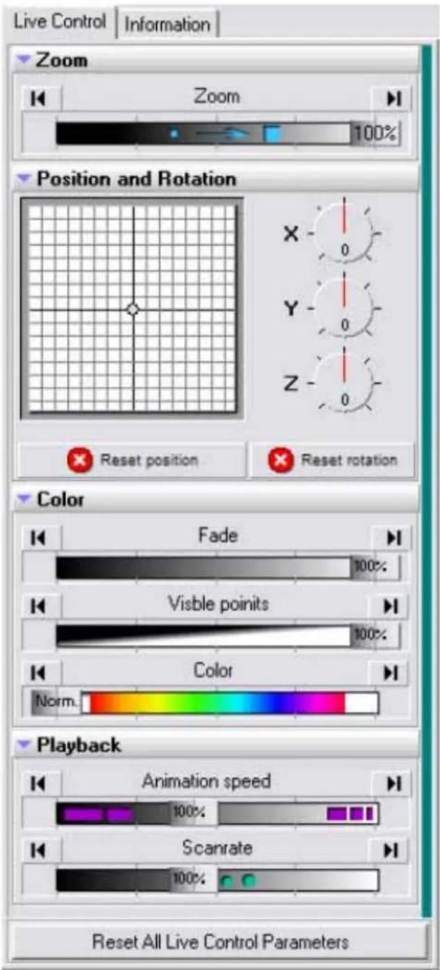
Live control during playback
The show software allows live control of several parameters in real time during cue playback. Live controls are accessed in the side panel to the right of the main window. The side panel contains two subpanels, Live Control and Information, which are selected using tabs above the panels.
In the Live Control sub-panel you can control:
- Zoom (size)
- X Position
- Y Position
- X Rotation
- Y Rotation
- Z Rotation
- Brightness
- Visible points
- Color
- Animation speed
- Scan rate
See the DMX Protocol included as Appendix 1 at the end of this manual for a complete overview of DMX modes, channels used and control options available.
Check that the RGB laser 1.6 is correctly and safely installed. If so, power up at the fixture's power on/off switch. If the fixture resets and starts up successfully, the fixture's DMX address appears in the display.
Setting DMX addresses
Basic principles
The DMX address of a fixture is the first channel used to receive control data within the range of 512 physical channels available in one DMX universe. If the fixture is set up to use 16 channels, for example, it will respond to commands on this first channel and the next 15 channels. Thus, if the DMX address is set to 48, channels 1 - 16 on the fixture will correspond to physical channels 48 - 63 at the DMX controller.
To avoid unexpected behavior, make sure that channels used by different fixtures do not overlap. In the example above, channel 64 is available as the DMX address for the next fixture.
Fixtures of the same type with the same DMX address will respond identically to commands from the control desk.
Allow enough channels for the fixture out of the 512 available. If the fixture is set up to use 16 channels, for example, the highest value you should set as DMX address is the first of those 16 channels, i.e. 497.
Setting a fixture's DMX address
DANGER! Before changing the DMX address, set the keyswitch to the OFF position to avoid accidental exposure.
The RGB Laser 1.6's DMX address is set manually using the control panel and display.
To set the fixture's DMX address:
- Set the keyswitch to the OFF position to avoid accidental exposure if the fixture reacts unexpectedly.
- Press the button repeatedly until DMX ADDR appears in the display
- Enter the DMX address submenu by pressing the UP button or the DOWN button once.
- Set the fixture's DMX address by using + to increase or - to decrease the address
- A short blink in the display illumination will show that the new value is stored
- After setting the DMX address, check that there is no possibility of accidental exposure before turning the key switch to the INTERNAL DMX position.
Selecting a DMX mode
The RGB Laser 1.6 offers a choice of four DMX control modes. It uses 4 DMX channels minimum and 16 channels maximum, depending on which DMX control mode is selected:
- Basic mode uses 4 DMX channels
- Standard mode uses 8 DMX channels
- Extended mode uses 12 DMX channels
• Full mode uses 16 DMX channels
The DMX mode is selected by sending a corresponding DMX value on fixture channel 1.
Show selection via DMX
If you are using an analog DMX desk, it is not possible to place all 432 possible show selections on one channel with 256 possible fader positions. The Player therefore uses two channels for show selection, one channel to select a Page, and the next channel to select a cue from the current Page. Pages can therefore be considered as banks.
To select a show:
- On channel 2 (PAGE), select a Page from 1-9 in the show software.
- On channel 3 (CUE), select one of the 48 Cues on the selected Page.
If you set both channel 2 and 3 faders to zero, show output stops unless you have set the fixture to run in stand-alone mode with DMX connected (see next section).
Running in stand-alone mode with DMX connected
When the RGB Laser 1.6 is receiving a DMX signal, stand-alone operation is disabled by default. To set the fixture to play in stand-alone mode when it is still connected to a DMX controller:
- Right-click on a cue
- Choose Properties... from the drop-down menu.
- Put a check in the checkbox Automatically play this cue after power up...
- Move channel 2 (PAGE) and 3 (CUE) faders to zero to play the cue in stand-alone mode.
Note that this cue will also play when you power the fixture on and it is not receiving a DMX signal.
DMX failure protection
The RGB Laser 1.6 automatically recognizes a valid DMX signal. If the signal fails because the DMX link is broken or disconnected, or if the DMX controller stops sending a valid DMX signal, output is shut down.
ILDA operation
The RGB laser 1.6 has a standard symmetrical ILDA input interface.
Any type of show controller with a symmetrical ILDA output can be connected to the fixture using a 1:1 25-pin Sub-D cable.
Make sure that your controller supports a +5 V Shutter signal at Pin 13.
A controller with non-symmetrical signals can be used if all negative input pins (14, 15, 18, 19, and 20) are connected to ground.
Important! The signals for x and y must not exceed +10 V and the signals for RGB must not exceed +5 V with reference to ground at any time!
After connecting your ILDA-compatible controller, power up the fixture and turn the key switch to the EXTERNAL position.
Service and Troubleshooting
DANGER! Protect your eyes with laser safety goggles suitable for the emissions from the fixture as described in the Specifications section at the end of this manual when working on or near the fixture, unless you have made sure that the fixture is powered off and that power cannot be applied accidentally. Do not look into the output window or laser beam.
Important! This fixture contains no user-serviceable or adjustable parts. Do not try to open the sealed dust-free optical module – doing so will destroy the optical coatings inside the fixture, allow dust to enter the module and invalidate the product guarantee. Even one speck of dust can cause serious damage to the laser.
Cleaning
Warning! Do not use water or any other liquid to clean the fixture.
Wipe the housing of the fixture with a damp (but not wet) cloth if necessary.
To maintain adequate cooling, dust must be cleaned from the fan and air vents periodically. Check and, if necessary, clean fixtures at regular intervals.
To clean the fan and air vents:
- Disconnect the data and power cables and allow the fixture to cool for at least 5 minutes.
- Remove dust and dirt from the fan blades, vent grill and heatsink using a soft brush, cotton swab, vacuum, or compressed air.
Replacing fuses
Warning! Do not bypass a fuse or replace it with one of another size or rating.
The RGB laser 1.6 uses two slow-blow 2.5 amp main fuses for protection against current overload. An indication that a fuse may have blown is that when power is applied, the LCD display does not light up and fans do not run.
If the fuse blows repeatedly, there is probably a fault. Disconnect the fixture from power and data and contact a Martin service technician.
To replace a fuse:
- Disconnect the power cable.
- Open the fuseholder (located next to the power cable entry) with a flat-headed screwdriver and remove the fuses for testing.
- Replace a defective fuse with a new 2.5 A slow blow, 5 x 20 mm glass-type fuse (available from Martin, P/N 05020010).
- Replace the fuseholder before reconnecting to power.
Firmware updates
If new firmware is released, it is included in a new version of the Martin RGB Laser Show software and made available on the Martin website at http://www.martin.com
When the show software is connected to the fixture, it checks the fixture's firmware. If it detects an older version, it displays a dialog box asking if you would like to update it. Click OK to allow the show software to automatically update the firmware.
Martin RGB Laser 1.6 Specifications
Physical
Size (L x W x H)....290 x 204 x 178 mm (11.5 x 8.1 x 7.0 in.)
Height with bracket attached 260 mm (10.3 in.)
Length with bracket attached 326 mm (12.9 in.)
Weight 11.2 kg (24.7 lb.)
Control and Programming
Control options ......DMX, ILDA, PC software (supplied), stand-alone autostart mode
Resolution x and y 12-bit
Resolution RGB intensity 8-bit
DMX channels 4, 8, 12 or 16
Demo sequence ...... Storage for 256 cues, can be edited/overwritten
Stand-alone memory 128 MB, 432 linkable/loopable cues
DMX address setting...... Onboard control panel with backlit LCD display
Stand-alone programming....PC software
Projection settings and data readouts...... Onboard control panel with backlit LCD display
Protocol ...... USITT DMX512-A
Laser
Class....4
Type......Diode laser, cw-emission
Pλ 440 nm-660 nm max. 2000 mW cw
White light output....1.3 W
Maximum output....1.6 W
Beam divergence.... 0.8 mrad
Wavelengths
Red 650 nm +/-5 nm
Green....532.5 nm +/-0.5 nm
Blue 446 nm +/-3 nm
Projector
Projection angle horizontal 80°
Projection angle vertical 80°
SASRT (step response time)....0.3 ms
Construction
Housing …… Aluminum
Finish .... Black
Ingress Protection rating IP 52
Installation
Orientation....Any
Minimum distance to persons and objects in beam zone 2 m (79 in.)
Minimum height above publicly accessible floor 3 m (10 ft.)
Minimum distance to illuminated surfaces 2 m (79 in.)
Minimum distance to combustible materials 1 m (40 in.)
Minimum clearance around device.... 30 cm (12 in.)
Relative humidity limits....0 – 90% non-condensing
Connections
AC power inlet....3-prong IEC male socket
Analog (ILDA) in/out.... 25-pin Sub-D
DMX in/out....5-pin locking XLR
Programming and uploads....USB 2.0 (via 6-pin XLR chassis connector)
Electrical
AC power....100-240 VAC nominal, 50/60 Hz
Power supply unit....Auto-ranging electronic switch-mode
Main fuses....2.5 AT (slow blow), 5 x 20 mm glass type, P/N 05020010
Maximum power and current
100V, 60Hz....1.8 A, 180 W
110V, 60Hz....1.7 A, 180 W
115V, 60Hz....1.7 A, 180 W
120V, 60Hz....1.7 A, 180 W
220V, 50Hz....0.7 A, 180 W
230V, 50Hz....0.7 A, 180 W
240V, 50Hz....0.7 A, 180 W
Measurements taken at nominal voltage. Allow for +/-10% variation.
Thermal
Maximum ambient temperature ( Ta ) 40°C (104°F)
Minimum ambient temperature ( Ta ) 5°C (41°F) non-condensing
Recommended storage temperature 20-25°C (68-77°F)
Acoustic
Sound pressure level....<42 dBA at 1 m, (3.3 ft.), steady state, Ta 25°C (77°F)
Approvals


US Safety .....IEC 60825-1 / FDA Laser Notice 50
US Federal standard....21 CFR 1040.10 and 1040.11(c)
Canadian safety ....CSA C22.2 No. 60950-1
EU Safety ...... EN 60950, EN 60825-1
EU EMC ......EN 55022, EN 55103-1, EN 55103-2, EN 61000-3-2, EN 61000-3-3
Included items
CD with Martin RGB Laser Show software, default cue library and fixture firmware (backup copy)
Two security keys for key switch....P/N 50521000
Interlock connector (AMP)....P/N 05347230
Adjustable mounting yoke....P/N 56600069
5 meter (16 ft.) 6-pin XLR to USB adaptor cable
3 m power cable, IEC, Schuko plug....P/N 11501020
1.8 m power cable, IEC, US plug....P/N 11501502
1.8 m power cable, IEC, without plug....P/N 11501010
User manual....P/N 35000189
Ordering Information
Martin RGB Laser 1.6 (in cardboard box).... P/N 90432000
Martin RGB Laser 1.6 (in flight case) P/N 90432001
Specifications subject to change without notice
Appendix 1: DMX Protocol
| BASIC | CHANNEL 1 | 0-31 | 33-95 | 97-159 | 161-223 | 225-255 | ||||||||||
| ACCESS | BLACKOUT | BASIC RANGE | STANDARD RANGE | EXTENDED RANGE | FULL RANGE | |||||||||||
| CHANNEL 2 | 0-15 | 17-31 | 33-47 | 49-63 | 65-79 | 81-95 | 97-111 | 113-127 | 129-255 | |||||||
| PAGE | 1 | 2 | 3 | 4 | 5 | 6 | 7 | 8 | 9 | |||||||
| CHANNEL 3 | 0-31 | CUE1=33..35, CUE2=37..39..., CUE46=221..223 | 225-255 | |||||||||||||
| CUE | BLACKOUT | 1 | 2 | 3 | 4 | 5 | 6 | 7 | 8 | 9 | 10 ... | ... 48 | ||||
| CHANNEL 4 | 0-15 | 17-31 | 33 ... ... 64 ... ... 128 ... ... 255 | |||||||||||||
| SPEED | 100% | PAUSE | 25% ... ... 50% ... ... 100% ... ... 200% | |||||||||||||
| STANDARD | CHANNEL 5 | 0-255 | ||||||||||||||
| FADE | Black ... ... Full brightness | |||||||||||||||
| CHANNEL 6 | 0-255 | |||||||||||||||
| ZOOM | Zero size ... ... Full size | |||||||||||||||
| CHANNEL 7 | 0-255 | |||||||||||||||
| X SIZE | Negative full size ... Zero size ... Positive full size | |||||||||||||||
| CHANNEL 8 | 0-255 | |||||||||||||||
| Y SIZE | Negative full size ... Zero size ... Positive full size | |||||||||||||||
| EXTENDED | CHANNEL 9 | 0-255 | ||||||||||||||
| Z ANGLE | 0 degrees ... ... 360 degrees | |||||||||||||||
| CHANNEL 10 | 0-255 | |||||||||||||||
| X POSITION | Left ... Center ... Right | |||||||||||||||
| CHANNEL 11 | 0-255 | |||||||||||||||
| Y POSITION | Down ... Center ... Up | |||||||||||||||
| CHANNEL 12 | 0-255 | |||||||||||||||
| VISIBLE POINTS | No visible points ... ... All points visible | |||||||||||||||
| FULL | CHANNEL 13 | 0-31 | 33-223 | 225-255 | ||||||||||||
| SCAN RATE | DEFAULT | 6K | 7K | 8K | 9K | 10K ... ... 29K | 30K | |||||||||
| CHANNEL 14 | 0-31 | 33-95 | 97-159 | 161-223 | 225-255 | |||||||||||
| RELEASE | DEFAULT | HOLD | LOOP | NEXT | STOP | |||||||||||
| CHANNEL 15 | 0-31 | 33-223 | 225-255 | |||||||||||||
| COLOR | DEFAULT | RED - ORANGE - YELLOW - LIME - GREEN - CYAN - BLUE - PURPLE - PINK - RED | WHITE | |||||||||||||
| CHANNEL 16 | 0-255 | |||||||||||||||
| RESERVED | RESERVED | |||||||||||||||
Appendix 2: Warning Label Location and Identification
When supplied, the Martin RGB Laser 1.6 is fitted with the warning labels illustrated below.
Warning! Do not cover these warning labels with sticky tape, labels, etc.
![graph TD A["Laser radiation warning label"] --> B["Mastering a laser aperture label"] B --> C["EMISSION LASER ON"] C --> D["Warming and classification label"] D --> E["INTERLOCK"] E --> F["Housing interlock label"] F --> G["DANGER"] style A fill:#FFD700,stroke:#333 style B fill:#FFD700,stroke:#333 s…](/content/2026/05/998682/images/a364238f5995e9c9d4a27231fd8954b12bd39cc287b204eed3225b1cd0c9aa35.jpg)
- RGB LASER 1.6 TM USER MANUAL
- DIMENSIONS
- CONTENTS
- REAR PANELS OVERVIEW
- SAFETY INFORMATION
- DANGER! CLASS 4 LASER PRODUCT
- GENERAL
- LASER SAFETY
- PROTECTING YOURSELF AND OTHERS FROM ELECTRIC SHOCK AND INJURY
- PROTECTING YOURSELF AND OTHERS FROM BURNS AND FIRE
- PROTECTING YOURSELF AND OTHERS FROM INJURY DUE TO FALLS
- INTRODUCTION
- FEATURES
- SPECIAL PRODUCT INFORMATION
- STORAGE TEMPERATURE
- TEMPERATURE STABILIZATION AT POWER ON
- INTERNAL MEMORY
- INSTALLATION
- CONNECTING TO AC POWER
- INSTALLING A POWER PLUG
- PHYSICAL INSTALLATION
- SUSPENDING FROM A SUPPORT
- PLACING ON A HORIZONTAL SURFACE
- CONNECTING TO A PC
- CONNECTING TO A DMX DATA LINK
- CONNECTING TO AN ILDA ANALOG CONTROL DEVICE
- ILDA ANALOG SUB-D CONNECTOR PINOUT
- OPERATION
- MONITORING FIXTURE STATUS
- STATUS MESSAGES IN THE DISPLAY
- USING THE CONTROL PANEL AND DISPLAY
- CONTROL PANEL
- CONTROL MENUS
- FIXTURE INFORMATION READOUTS
- FIXTURE SETTINGS AND MANUAL ADJUSTMENT
- DEMO MODE
- USING THE MARTIN RGB LASER SHOW SOFTWARE
- MANAGING SHOWS IN WORKSPACES
- PREVIEWING AND TRIGGERING CUES, SELECTING PAGES
- CREATING, EDITING AND IMPORTING FRAMES AND ANIMATIONS
- CUE PROPERTIES
- PROPERTIES... → SETTINGS
- ANIMATION
- OPTIONS
- PROPERTIES... → OUTPUT
- SAMPLE RATE
- OVERWRITE PROJECTOR COLOR CHANNELS SETTINGS FOR THIS CUE
- PROPERTIES... → VECTOR SETTINGS
- PROPERTIES... → INFORMATION
- SETTINGS MENU
- PROJECTOR SETTINGS
- PROJECTOR SETTINGS... → MASTER SCAN RATE AND COLOR SETTINGS
- SAMPLE RATE AND COLOR SHIFT
- COLOR OUTPUT LEVELS
- PROJECTOR SETTINGS... → VECTOR DISPLAY SETTINGS
- SPACING
- ANCHORS AND ANGLE OPTIMIZATION
- GEOMETRICAL CORRECTION
- MOVING CUES
- LINKING CUES
- STAND-ALONE MODE
- UPLOADING CUES FROM YOUR PC TO THE FIXTURE
- LIVE CONTROL DURING PLAYBACK
- SETTING DMX ADDRESSES
- BASIC PRINCIPLES
- SETTING A FIXTURE'S DMX ADDRESS
- DANGER! BEFORE CHANGING THE DMX ADDRESS, SET THE KEYSWITCH TO THE OFF POSITION TO AVOID ACCIDENTAL EXPOSURE
- SELECTING A DMX MODE
- SHOW SELECTION VIA DMX
- RUNNING IN STAND-ALONE MODE WITH DMX CONNECTED
- DMX FAILURE PROTECTION
- ILDA OPERATION
- SERVICE AND TROUBLESHOOTING
- CLEANING
- REPLACING FUSES
- FIRMWARE UPDATES
- MARTIN RGB LASER 1.6 SPECIFICATIONS
- PHYSICAL
- CONTROL AND PROGRAMMING
- LASER
- WAVELENGTHS
- PROJECTOR
- CONSTRUCTION
- CONNECTIONS
- ELECTRICAL
- MAXIMUM POWER AND CURRENT
- THERMAL
- ACOUSTIC
- APPROVALS
- INCLUDED ITEMS
- ORDERING INFORMATION
- APPENDIX 1: DMX PROTOCOL
- APPENDIX 2: WARNING LABEL LOCATION AND IDENTIFICATION
Brand : MARTIN
Model : RGB Laser 1 6
Category : Laser projector