
K7P3M075WPCR - Lighting HAGER - Free user manual and instructions
Find the device manual for free K7P3M075WPCR HAGER in PDF.


| Product Type | Pre-wired Plug and Socket for Dimmable Luminaires |
| Model | K7P3M075WPCR |
| Brand | Hager |
| Rated Current | 6 A |
| Rated Voltage | 230 V AC (typical) |
| Cable Length | 3 m |
| Cable Core Size | 0.75 mm2 |
| Number of Cores | 5 (Line, Neutral, CPC, DA+, DA-) |
| Number of Pins (Plug) | 7 |
| Connector Type | Klik 7-pin plug with KLPCR/7 ceiling rose socket |
| Standards | BS 5733:2010, BS EN 61535 |
| Short Circuit Rating | 1500 A conditional |
| Cable Material | Low Smoke Zero Halogen (LSZH) |
| Application | Dimmable luminaires with DALI/DSI control |
| Safety Feature | Safe on-load connection/disconnection with earth first make |
| System Compatibility | Klik 7 marshalling boxes (KLMB) and accessories |
Frequently Asked Questions - K7P3M075WPCR HAGER
User questions about K7P3M075WPCR HAGER
0 question about this device. Answer the ones you know or ask your own.
Ask a new question about this device
Download the instructions for your Lighting in PDF format for free! Find your manual K7P3M075WPCR - HAGER and take your electronic device back in hand. On this page are published all the documents necessary for the use of your device. K7P3M075WPCR by HAGER.
USER MANUAL K7P3M075WPCR HAGER
Klik Lighting Connection
Klik is the lighting connection system for all your lighting designs, benefiting from its modular and adaptable design. From concept to commissioning, Klik adapts to meet your requirements.
:hager

natural_image
Overhead view of people working at a wooden table with white panels and tools, no visible text or symbols
natural_image
Two white geometric shapes on a plain background, one folded and one tilted (no text or symbols)Klik is the lighting connection system for all your lighting designs.
Established in the UK in the 1980s with its innovative 4 Pin plug & socket, installers have come to know and love Klik for its speed & ease of installation.
Klik has continued to develop to meet the changing needs of modern lighting connection & control systems through the Klik 4 & Klik 7 Ranges.
But the ethos has stayed the same...
Just Klik and forget.
From Start to Finish.
With its pre-wired plugs, Klik saves time on site, eliminates the chance of poor connections and allows for the system to adapt as needs change.
Luminaires can be plugged-in in seconds, with absolute safety and without circuit isolation. The secure, simultaneous mechanical & electrical connection gives complete confidence.
01 Design

natural_image
Icon of an open book with a pencil writing on it, symbolizing study or editing (no text present)Klik is able to exploit the benefits of pre-fabricated wiring systems through its modular and adaptable design. From concept to commissioning, Klik adapts to meet your requirements.
By being a pluggable system, the prospect of future refurbishments is also nothing to worry about, lights or groups of lights can be relocated quickly and easily.
02 Install

natural_image
Blue wrench icon with two blue hexagons below (no text or symbols)The Klik connector system brings plug-in convenience and versatility to lighting. Lights can be plugged-in, in seconds, with absolute safety, without circuit isolation.
The unique design prevents any unwanted disconnections due to load on cables or vibrations.
03 Use

natural_image
Simple icon of a light bulb with radiating lines, symbolizing an idea or illumination (no text or symbols)Klik is a truly fit and forget lighting connection system. With a range of settings for daylight linked dimming, occupancy sensing photocell control for standard luminaires and DALI control, after Klik is installed, you'll forget it's even there.
04 Adapt

natural_image
Abstract icon of two interlocking puzzle pieces in blue and dark blue, no text or symbols present.Part of the problem with traditional lighting systems comes when a building or office space needs to change. The inherent benefit of Klik is that adapting to a new layout is as easy as plugging in a plug.
What Klik can do for you
Over 75% of existing lighting installations are thought to be out of date and unable to meet current design standards.
With Klik 7, we provide a system which is energy efficient, meets current design standards and takes into account the usage and function of a space, responding to daylight levels as well as occupancy and footfall.
Benefits - At a Glance
Klik 3 / 4 Klik 7


| Connection | Safe on-load connection / disconnection | √ | √ |
| Superior electromechanical connection | √ | √ | |
| Control | Occupancy sensing for on / off control | √ | √ |
| Occupancy sensing for daylight linked on / off control | √ | √ | |
| Lux level ‘trimming’ during commissioning | ✕ | √ | |
| Automatic dimming (daylight linked) | ✕ | √ | |
| Manual dimming (via wall switch) | ✕ | √ | |
| DALI / DSI | ✕ | √ |

By following the information CIBSE provide, building operators, designers and employers are better able to demonstrate compliance with UK building regulations and a number of lighting related BS EN standards, by incorporating the following Klik features.
CIBSE
Use Occupancy Sensors
Use Daylight Sensors
Have a Maintenance Plan


Safe on-load connection
Luminaires can be connected in seconds in absolute safety, without circuit isolation, as all live contacts are inaccessible and the earth connection is made before any other, facilitating a simplified maintenance plan.
02 0301
Electro Mechanical Connection
All Klik plugs feature a unique plug-in method which achieves a simultaneous mechanical and electrical connection.

Occupancy Sensing
Our range of occupancy sensors can provide presence and absence control of lighting, providing energy savings by switching lights on or off depending on the usage of the room.
04

DALI Control
DALI (digital addressable lighting interface) is a broadcast communication system that brings digital technology to lighting. Our 7 pin Klik products offer full compatibility with DALI control solutions.
05

Trimming of lux level
DALI based occupancy sensors enable trimming of lux level at commissioning stage to ensure optimum final lighting levels, when used with compatible, dimmable luminaire.
06

Daylight Link
Klik allows for automatic lighting control which can provide energy savings by not operating when sufficient light levels exist.

A Fast, Adaptable & Secure Solution.
Providing an optimal lux level for the occupiers of a building is just one of the often overlooked functions of a quality lighting connection system.
Klik 7 provides an adaptable solution to any challenge faced in designing a modern, scalable lighting system, by ensuring the lux levels of dimmable luminaires can be adjusted during commissioning and, most importantly, after feedback from the occupiers.
The Value of Control
A basic level of control can be achieved easily with the use of occupancy sensors, by 'trimming' the lux level of dimmable luminaires to the required level at commissioning stage, helping to avoid costly problems later.
As lighting technologies and their applications continue to evolve, so too must the lighting connection systems used. The Klik range, with its combination of occupancy sensors, motion detectors, ceiling roses and marshalling boxes, can facilitate the inclusion of more complex control options as required.
Klik 7 provides all the benefits of Klik 4, creating a truly scalable level of control when matched with our sensors or other higher level supervisory systems, with the advantages associated with a built in control pair.
Application Examples
Application 1 - Office with no natural light
| Sensor settings Presence |
| Lux sensor used No |
| Wall switching None - auto only |
- Two KLMB/KLDS marshalling boxes
- No natural light
- Standard or digital luminaires
- Auto on when entering room
- 20 Minute time out when vacant

flowchart
graph TD
    A["Node 1"] --> B["Central Node"]
    C["Node 2"] --> B
    D["Node 3"] --> B
    E["Node 4"] --> B
    F["Node 5"] --> B
    G["Node 6"] --> B
    H["Node 7"] --> B
    I["Node 8"] --> B
    J["Node 9"] --> B
    K["Node 10"] --> B
    L["Node 11"] --> B
    M["Node 12"] --> B
    N["Node 13"] --> B
    O["Node 14"] --> B
    P["Node 15"] --> B
    Q["Node 16"] --> B
    R["Node 17"] --> B
    S["Node 18"] --> B
    T["Node 19"] --> B
    U["Node 20"] --> B
    V["Node 21"] --> B
    W["Node 22"] --> B
    X["Node 23"] --> B
    Y["Node 24"] --> B
    Z["Node 25"] --> B
    AA["Node 26"] --> B
    AB["Node 27"] --> B
    AC["Node 28"] --> B
    AD["Node 29"] --> B
    AE["Node 30"] --> B
    AF["Node 31"] --> B
    AG["Node 32"] --> B
    AH["Node 33"] --> B
    AI["Node 34"] --> B
    AJ["Node 35"] --> B
    AK["Node 36"] --> B
    AL["Node 37"] --> B
    AM["Node 38"] --> B
    AN["Node 39"] --> B
    AO["Node 40"] --> B
    AP["Node 41"] --> B
    AQ["Node 42"] --> B
    AR["Node 43"] --> B
    AS["Node 44"] --> B
    AT["Node 45"] --> B
    AU["Node 46"] --> B
    AV["Node 47"] --> B
    AW["Node 48"] --> B
    AX["Node 49"] --> B
    AY["Node 50"] --> B
Application 2 - Office with windows on two sides
| Sensor settings Presence | |
| Lux sensor used Yes | |
| Wall switching Optional | |
- One dual supply KLMB marshalling boxes & one standard KLMB box
- Auto on when entering room
- Natural light on two sides
- Digital luminaires adjacent to windows - standard or digital luminaires elsewhere
- 2 x digital sensors & 1 x standard sensor.
- 20 minute time out when vacant

flowchart
graph TD
    subgraph Zone_A
        A1["Zone A"] --> B1["Component"]
        A2["Zone A"] --> B1
        A3["Zone A"] --> B1
        A4["Zone A"] --> B1
        A5["Zone A"] --> B1
        A6["Zone A"] --> B1
        A7["Zone A"] --> B1
        A8["Zone A"] --> B1
        A9["Zone A"] --> B1
        A10["Zone A"] --> B1
        A11["Zone A"] --> B1
        A12["Zone A"] --> B1
        A13["Zone A"] --> B1
        A14["Zone A"] --> B1
        A15["Zone A"] --> B1
        A16["Zone A"] --> B1
        A17["Zone A"] --> B1
        A18["Zone A"] --> B1
        A19["Zone A"] --> B1
        A20["Zone A"] --> B1
        A21["Zone A"] --> B1
        A22["Zone A"] --> B1
        A23["Zone A"] --> B1
        A24["Zone A"] --> B1
        A25["Zone A"] --> B1
        A26["Zone A"] --> B1
        A27["Zone A"] --> B1
        A28["Zone A"] --> B1
        A29["Zone A"] --> B1
        A30["Zone A"] --> B1
        A31["Zone A"] --> B1
        A32["Zone A"] --> B1
        A33["Zone A"] --> B1
        A34["Zone A"] --> B1
        A35["Zone A"] --> B1
        A36["Zone A"] --> B1
        A37["Zone A"] --> B1
        A38["Zone A"] --> B1
        A39["Zone A"] --> B1
        A40["Zone A"] --> B1
    end
    subgraph Zone_B
        B1_1["A"] --> B1_2["B"]
        B1_2 --> B1_3["B"]
        B1_3 --> B1_4["B"]
        B1_4 --> B1_5["B"]
        B1_5 --> B1_6["B"]
        B1_6 --> B1_7["B"]
        B1_7 --> B1_8["B"]
        B1_8 --> B1_9["B"]
        B1_9 --> B1_10["B"]
        B1_10 --> B1_11["B"]
        B1_11 --> B1_12["B"]
        B1_12 --> B1_13["B"]
        B1_13 --> B1_14["B"]
        B1_14 --> B1_15["B"]
        B1_15 --> B1_16["B"]
        B1_16 --> B1_17["B"]
        B1_17 --> B1_18["B"]
        B1_18 --> B1_19["B"]
        B1_19 --> B1_20["B"]
    end
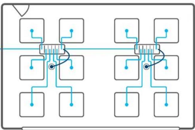
Application 3 - Klik connection with 3rd party control
| Sensor settings Presence |
| Lux sensor used Optional |
| Wall switching Optional |
- Two KLMB marshalling boxes
- Natural light on one side
- Digital luminaires
- Auto on when entering room
- 3rd Party head-end lighting control/supervisory system
DALI / DSI
flowchart
graph TD
    A["Input"] --> B["Node 1"]
    A --> C["Node 2"]
    A --> D["Node 3"]
    A --> E["Node 4"]
    A --> F["Node 5"]
    G["Input"] --> H["Node 6"]
    G --> I["Node 7"]
    G --> J["Node 8"]
    G --> K["Node 9"]
    G --> L["Node 10"]
    M["Input"] --> N["Node 11"]
    M --> O["Node 12"]
    M --> P["Node 13"]
    M --> Q["Node 14"]
    M --> R["Node 15"]
Klik 7
Delivering all the time saving, flexibility and secure lighting connection benefits of Klik 4, Klik 7 offers the additional benefit of an embedded control pair for the dimming of luminaires, providing a scalable approach to lighting control.
Developed to specifically address the latest lighting technologies, Klik 7 has evolved as an essential element of controllable lighting solutions.

natural_image
Electrical panel with multiple switches and a magnified inset showing terminal connections (no visible text or symbols)Essential ‘trimming’ of lux levels to optimise the light in a room can easily be implemented through the use of DALI enabled Occupancy Sensors, which can then be adjusted at the commissioning phase and if required, after occupier feedback.
Klik 7 facilitates a truly scalable approach to lighting control, without compromising speed, security or flexibility of installation.
From intelligent occupancy sensors to manage lux levels and common control requirements, to sophisticated 3rd party ‘head end’ control and supervisory solutions, Klik 7 facilitates all your lighting application requirements.
Klik 4
Klik 4 is a modular plug-in marshalling solution for lighting systems that provides simultaneous mechanical and electrical connection in one click-in action. Designed for on-load connection & disconnection, Klik 4 allows individual light fittings to be removed or added without affecting other fittings on the circuit.
3 pin moulded plugs and leads distribute switch live, neutral and earth with 4 pin providing an additional connection, normally a permanent live for emergency lighting.
Pre-wired or self-wired plugs provide a highly adaptable solution for when systems need to be altered. Klik significantly cuts down on installation time by limiting the testing requirements at the commissioning stage.
natural_image
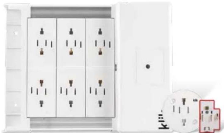
Exterior view of a white electrical enclosure with multiple socket switches (no text or symbols visible)
Project Name: Facebook Data Centre
Location: Clonee, Co. Meath, Ireland.
Products Used: Klik 7 with DALI sensors
Klik 7 and DALI sensors were chosen to provide lighting connection and control, to be installed in a Facebook Data Centre in Clonee, Co. Meath, Ireland.
The 250 acre Clonee Data Centre is home to servers that hold data from Instagram, WhatsApp, Messenger, and Oculus. Introduced in 2015, construction began on the €200m facility in April 2016 and rapidly grew to be the largest construction project in Ireland at the time.
After 7.2 million hours completed on the construction site by nearly 1,550 workers at peak, the first two buildings called Clonee 1 and 2, are now up and running. Clonne 3 is on the path to completion and Facebook is hoping to have it finished next year, while a planning application for Clonee 4 and 5 has been lodged. With the employment of 1,000 – 1,500 people for continuous periods of time, projects of this nature are remarkably good for the local and regional economy.
In an effort to stay energy efficient, Facebook designed an agreement with Brookfield renewable Partners, confirming that the site is 100% powered by wind energy and actively investing in constructing renewable generation capacity. At present, Facebook has stated it has added 2,500MW of renewable infrastructure that includes solar, wind and hydro globally in the last year alone and continues to increase as time goes on.
Mercury Engineering needed a lighting solution for wiring all the DALI fittings throughout the numerous data halls, and office spaces that occupy the building. Hager presented the Klik solution valued at €200k with the agreement to customise the length and part numbers to match the specifications of the project. After the decision was finalised, Mercury Engineering, distributor NEW and Hager worked closely together to come to an arrangement on time-scale, quantities and supply.
Hager's Klik range is a solution for any lighting design scenario. The Klik offer allows for automatic lighting control that provides energy savings by not operating when there are sufficient light levels present. With a range of settings for daylight linked dimming, occupancy sensing and DALI control, Klik was an ideal lighting solution for the Facebook Data Centre project.
Lighting Connection
Lighting creates an impression. Klik, our lighting connection system provides the roots to a buildings lighting system, allowing it to adapt and grow with ease. Controls, including occupancy sensors, ensure that light is only available when needed and tailored to a users needs.

natural_image
Row of identical rectangular electronic components with black cylindrical pins arranged in a diamond pattern (no text or symbols visible)Klik
Klik 7 14
Klik 4 22
Controls
Motion Detectors 19
Technical Pages 33
natural_image
Exterior view of a modern office building (no signage)KLMB4W
Marshalling Boxes - Wire In, Plug Out
Characteristics:
- The KLMB marshalling box allows the connection and control of multiple luminaires. The marshalling box utilises a robust extruded aluminium body.
-7 Pole.
- 4, 6, 8, 10 & 12 outlets.
- 16A Rated BS 5733:2010
- Short circuit tested: 1500A conditional rating.
Description Cat ref.
Marshalling Box, Single Supply, Wire In, Plug Out
4 Way KLMB4W
6 Way KLMB6W
8 Way KLMB8W
10 Way KLMB10W
12 Way KLMB12W
Marshalling Box, Dual Channel, Wire In, Plug Out
8 Way, 4/4 KLMB244W
10 Way, 5/5 KLMB255W
12 Way, 6/6 KLMB266W

KLMB5P
Marshalling Boxes - Plug In, Plug Out
Characteristics:
- The KLMB marshalling box allows the connection and control of multiple luminaires. The marshalling box utilises a robust extruded aluminium body.
- 7 Pole.
- 5, 7, 9 & 11 outlets.
- 16A Rated BS 5733:2010
- Short circuit tested: 1500A conditional rating.
Description Cat ref.
Marshalling Box, Single Supply, Plug In, Plug out
5 Way KLMB5P
7 Way KLMB7P
9 Way KLMB9P
11 Way KLMB11P

natural_image
White electrical plug with multiple circuit breakers and a terminal block (no visible text or symbols)K7B1M075WPCR
Klik 7 Pre-wired Plugs with Sockets
Characteristics:
- Connections to the luminaire are made via a pre-wired plug and lead. All leads are low smoke zero halogen and are factory connected and tested.
- Standard, digital and emergency luminaires.
- Short circuit tested: 1500A conditional rating.
- Cable standard BS 7211.
Description Cat ref.
Pre-wired Plugs and Sockets for Standard Luminaires
6A Luminaire Lead 1.5m 0.75mm² 3 Core Plug to Wire + KLPCR7 K7B1M075WPCR
6A Luminaire Lead 3m 0.75mm² 3 Core Plug to Wire + KLPCR7 K7B3M075WPCR
Pre-wired Plugs and Sockets for Standard Luminaires with Emergency
6A Luminaire Lead 1.5m 0.75mm² 4 Core Plug to Wire + KLPCR7 K7J1M075WPCR
6A Luminaire Lead 3m 0.75mm² 4 Core Plug to Wire + KLPCR7 K7J3M075WPCR
Pre-wired Plugs and Sockets for Dimmable Luminaires
6A Luminaire Lead 1.5m 0.75mm² 5 Core Plug to Wire + KLPCR7 K7P1M075WPCR
6A Luminaire Lead 3m 0.75mm² 5 Core Plug to Wire + KLPCR7 K7P3M075WPCR
Pre-wired Plugs and Sockets for Dimmable Luminaires with Emergency
6A Luminaire Lead 1.5m 0.75mm 6 Core Plug to Wire + KLPCR7 K7T1M075WPCR
6A Luminaire Lead 3m 0.75mm 6 Core Plug to Wire + KLPCR7 K7T3M075WPCR
Klik 7 Pre-wired Plugs
Characteristics:
- Connections to the luminaire are made via a pre-wired plug and lead. All leads are low smoke zero halogen and are factory connected and tested.
- Standard, digital and emergency luminaires.
- Short circuit tested: 1500A conditional rating.
- Cable standard BS 7211.
- New for 2019 - references with 1m cable length will be provided as 1.5m.
We have recently improved our range of Klik 7 pre-wired leads. As part of this process, we have changed how our part references work. For example KLB/3/0-75W will now become K7B3M075W. For a full supercession chart, see page 30.
K7
Range
B
Function
3M
Length
075
Core Size
W
Wired or Plug End
A Link Lead, Power
G Link Lead, Power, Emergency
K Link Lead, Power, Emergency, Switched Line
Z Link Lead, Power, Emergency, Switched Line, Control
B Standard Luminaire
J Standard Luminaire, Emergency
P Dimmable Luminaire
T Dimmable Luminaire, Emergency
E Emergency Exit Luminaire
F Switch Drop Lead
W Control, +/- & Cpc
Description Cat ref.
Pre-wired Plugs for Standard Luminaires
6A Luminaire Lead 1.5m 0.75mm² 3 Core Plug to Wire K7B1M075W
6A Luminaire Lead 3m 0.75mm² 3 Core Plug to Wire K7B3M075W
6A Luminaire Lead 5m 0.75mm² 3 Core Plug to Wire K7B5M075W
6A Luminaire Lead 7m 0.75mm² 3 Core Plug to Wire K7B7M075W
10A Luminaire Lead 1.5m 1mm² 3 Core Plug to Wire K7B1M1W
10A Luminaire Lead 3m 1mm² 3 Core Plug to Wire K7B3M1W
10A Luminaire Lead 5m 1mm² 3 Core Plug to Wire K7B5M1W
10A Luminaire Lead 7m 1mm² 3 Core Plug to Wire K7B7M1W
16A Luminaire Lead 3m 1.5mm² 3 Core Plug to Wire K7B3M15W
16A Luminaire Lead 5m 1.5mm² 3 Core Plug to Wire K7B5M15W
Pre-wired Plugs for Standard Luminaires with Emergency
6A Luminaire Lead 1.5m 0.75mm² 4 Core Plug to Wire K7J1M075W
6A Luminaire Lead 3m 0.75mm² 4 Core Plug to Wire K7J3M075W
6A Luminaire Lead 5m 0.75mm² 4 Core Plug to Wire K7J5M075W
6A Luminaire Lead 7m 0.75mm² 4 Core Plug to Wire K7J7M075W
6A Luminaire Lead 9m 0.75mm² 4 Core Plug to Wire K7J9M075W
10A Luminaire Lead 1.5m 1mm² 4 Core Plug to Wire K7J1M1W
10A Luminaire Lead 3m 1mm² 4 Core Plug to Wire K7J3M1W
10A Luminaire Lead 5m 1mm² 4 Core Plug to Wire K7J5M1W
10A Luminaire Lead 7m 1mm² 4 Core Plug to Wire K7J7M1W
10A Luminaire Lead 9m 1mm² 4 Core Plug to Wire K7J9M1W
16A Luminaire Lead 3m 1.5mm² 4 Core Plug to Wire K7J3M15W
16A Luminaire Lead 5m 1.5mm ^2 4 Core Plug to Wire K7J5M15W
16A Luminaire Lead 3m 1.5mm² 4 Core Plug to Plug K7J3M15P
16A Luminaire Lead 5m 1.5mm² 4 Core Plug to Plug K7J5M15P
16A Luminaire Lead 7m 1.5mm² 4 Core Plug to Plug K7J7M15P
Pre-wired Plugs for Emergency Exit Luminaires
16A Luminaire Lead 3m 1.5mm² 3 Core Plug to Wire K7E3M15W
16A Luminaire Lead 5m 1.5mm² 3 Core Plug to Wire K7E5M15W
16A Luminaire Lead 7m 1.5mm² 3 Core Plug to Wire K7E7M15W
16A Luminaire Lead 11m 1.5mm² 3 Core Plug to Wire K7E11M15W
natural_image
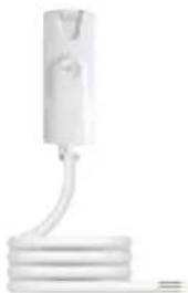
Simple line drawing of a white cylindrical object with a coiled base, no text or symbols present.K7B1M075W

natural_image
White medical or laboratory device with a coiled tube and red connector (no visible text or symbols)K7J1M075W
natural_image
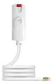
White medical device with attached tubing and a small connector (no visible text or symbols)K7T3M075W
Klik 7 Pre-wired Plugs for Dimmable Luminaires
Description Cat ref.
Pre-wired Plugs for Dimmable Luminaires
6A Luminaire Lead 1.5m 0.75mm² 5 Core Plug to Wire K7P1M075W
6A Luminaire Lead 3m 0.75mm² 5 Core Plug to Wire K7P3M075W
6A Luminaire Lead 5m 0.75mm² 5 Core Plug to Wire K7P5M075W
6A Luminaire Lead 7m 0.75mm² 5 Core Plug to Wire K7P7M075W
10A Luminaire lead 1.5m 1mm² 5 core Plug to Wire K7P1M1W
10A Luminaire Lead 3m 1mm² 5 Core Plug to Wire K7P3M1W
10A Luminaire Lead 5m 1mm² 5 Core Plug to Wire K7P5M1W
10A Luminaire Lead 7m 1mm² 5 Core Plug to Wire K7P7M1W
16A Luminaire lead 1.5m 1.5mm² 5 core Plug to Wire K7P1M15W
16A Luminaire Lead 3m 1.5mm² 5 Core Plug to Wire K7P3M15W
16A Luminaire Lead 5m 1.5mm² 5 Core Plug to Wire K7P5M15W
16A Luminaire Lead 7m 1.5mm² 5 Core Plug to Wire K7P7M15W
Pre-wired Plugs for Dimmable Luminaires with Emergency
6A Luminaire Lead 1.5m 0.75mm² 6 Core Plug to Wire K7T1M075W
6A Luminaire Lead 3m 0.75mm² 6 Core Plug to Wire K7T3M075W
6A Luminaire Lead 5m 0.75mm² 6 Core Plug to Wire K7T5M075W
6A Luminaire Lead 7m 0.75mm² 6 Core Plug to Wire K7T7M075W
10A Luminaire Lead 1.5m 1mm² 6 Core Plug to Wire K7T1M1W
10A Luminaire Lead 3m 1mm² 6 Core Plug to Wire K7T3M1W
10A Luminaire Lead 5m 1mm² 6 Core Plug to Wire K7T5M1W
10A Luminaire Lead 7m 1mm² 6 Core Plug to Wire K7T7M1W
16A Luminaire Lead 3m 1.5mm² 6 Core Plug to Wire K7T3M15W
16A Luminaire Lead 5m 1.5mm² 6 Core Plug to Wire K7T5M15W
16A Luminaire Lead 3m 1.5mm² 6 Core Plug to Plug K7T3M15P
16A Luminaire Lead 5m 1.5mm² 6 Core Plug to Plug K7T5M15P
16A Luminaire Lead 7m 1.5mm² 6 Core Plug to Plug K7T7M15P
Klik 7 Pre-wired Marshalling Box Link Leads
Characteristics:
- The link leads are used to connect KLMB to KLMB. All leads are low smoke zero halogen and are factory connected and
tested. Note: to ensure correct link lead selection see the connection key on page. - 1.5mmCSA.
- 3m, 5m & 10m lengths.
- Standard, Digital and Emergency Luminaires.
- 16A Rated
- BS 5733:2010, BS EN 61535.
- Short circuit tested: 1500A conditional rating.
- Cable standard BS 6500 & BS 7211.

natural_image
Two white electrical connectors with coiled cable, no visible text or symbolsK7A3M15P
Description Cat ref.
Pre-wired Link Leads - L, N, CPC
16A Luminaire Lead 10m 1.5mm² 3 Core Plug to Plug K7A10M15P
16A Luminaire Lead 5m 1.5mm² 3 Core Plug to Plug K7A5M15P
Pre-wired Link Leads - L, N, CPC, Emergency
16A Link Lead 10m 1.5mm² 4 Core Plug to Plug K7G10M15P
16A Link Lead 5m 1.5mm² 4 Core Plug to Plug K7G5M15P
Pre-wired Link Leads - L, N, SL, CPC, Emergency
16A Link Lead 5m 1.5mm² 5 Core Plug to Plug K7K5M15P
Pre-wired Link Leads - CPC, DA+, DA-
6A DALI Link Lead 3m 0.75mm² 3 Core Plug to Wire K7W3M075W
6A DALI Link Lead 5m 0.75mm² 3 Core Plug to Wire K7W5M075W
Pre-wired Link Leads - L, N, SL, CPC, DA+, DA-, Emergency
16A Link Lead 3m 1.5mm² 7 Core Plug to Plug K7Z3M15P
16A Link Lead 5m 1.5mm² 7 Core Plug to Plug K7Z5M15P
Ceiling Roses
Characteristics:
- 7 Pole conduit box / surface connector to allow the easy connection of digital lighting within traditional fixed wire installations.
The connector is fitted directly to trunking or conduit allowing the luminaire to be connected / disconnected via the pluggable luminaire lead.
-7 Pole.
- 16A Rated.
- Standards: BS 5733:2010.
- Short circuit tested: 1500A conditional rating.
Description Cat ref.
16A 7 Pin Ceiling Rose KLPCR/7
16A 7 Pin Wireable Plug & Ceiling Rose K7PLUGPCR

natural_image
White handheld electronic device with multiple ports and a strap (no visible text or symbols)KLPCR7

natural_image
Exterior view of a white industrial electrical enclosure with multiple circuitry (no visible text or symbols)K7PLUGPCR
Wireable / Rewireable Plug
Characteristics:
- 7 Terminal plug, enabling you to make leads on site to the configuration required.
- Complies with BS EN 61535-2009+A1-2013
- Enables you to add the plug after cable routing, for example when cables pass through walls.
Description Cat ref.
16A Wireable Klik 7 Plug K7PLUG

K7PLUG

natural_image
Exterior view of a modern office ceiling light fixture with adjustable arm and base (no text or symbols visible)EEK515P

EEK001
Occupancy Sensors with Remote Programming & Control Options
Characteristics:
- EEK520B - Detector for control of digital (DSI/DALI) luminaires
- Direct control of a light load.
- Lux level and ON delay adjustable via potentiometers or EEK001 remote control.
- DALI/DSI bus output accommodates up to 24 ballasts.
- 230V wall switch override.
- Presence or absence detection available.
-EEK523P - As EEK520B but pre-wired with 3m Lead
-EEK525P - As EEK520B but pre-wired with 5m Lead
-EEK513P-detector for control of standard luminaires (On/Off)
- Presence or Absence detection available.
- Programmable from EEK001
- 7m Range
-EEK515P - As EEK513P but pre-wired with 5m Lead
- EEK001 - IR programming tool
- Installer remote control to commission settings.
- EEK002 - IR remote control
- Customer remote control for override operation.
- Complies with BS EN 60669-1 & BS EN 60669-2-1.
Description Cat ref.
Wireable Digital PIR Occupancy Sensor - Dimmable & Daylight Linked EEK520B
Pluggable Digital PIR Occupancy Sensor 3m lead - Dimmable & Daylight Linked EEK523P
Pluggable Digital PIR Occupancy Sensor 5m lead - Dimmable & Daylight Linked EEK525P
Flush Mounted Standard Occupancy Sensor (without cable) EEK510B
Pluggable PIR Occupancy Sensor 3m lead - On / Off & Daylight Linked EEK513P
Pluggable PIR Occupancy Sensor 5m lead - On / Off & Daylight Linked EEK515P
Pre-Wired PIR Occupancy Sensor 3m lead - On / Off & Daylight Linked EEK513W
Programming Tool EEK001
Remote Control for the End User EEK002
Backbox Accessory for Surface BESA Detectors EEK005
Semi-Recessed Occupancy Sensor
Characteristics:
- The presence area is especially suitable in offices, where there may be notional corridors.
- EE810 - 1 channel detector
- Provides direct control of a light load or can be used as a slave with EE811 for enlargement of detection area.
- Lux level and ON delay (duration or pulse) defined via potentiometers.
- Test mode in order to set lux level and the detection pattern.
- EE811 - 2 channel detector
- Lux level and ON delay adjustable via potentiometers.
- Input for slave (EE810) and/or remote push button.
- 230V wall switch override
- Complies with BS EN 60669-1 & BS EN 60669-2-1.
Description Cat ref.
Presence Detector 1 Channel EE810
Presence Detector 2 Channel EE811
Surface Mounting Box for EE810 and EE811 EE813
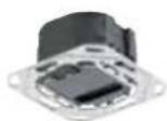

EE810
Hyper Frequency Detector
Characteristics:
- The detection range diameter is adjustable from one to eight metres. The hyper frequency sensor allows for detection of movement through partitions (drywall, wood, glass) independent of temperature detection.
Features
- 230V AC.
- Detection area 360°.
- Complies with BS EN 60669-1, BS EN 60669-2-1.

natural_image
Close-up of a white cylindrical object with a dark top and a small protruding rod (no visible text or symbols)EE883
Description Cat ref.
360° Hyper Frequency Sensor EE883
Protection Basket for Hyper Frequency Sensor EEK006
Corridor Motion Detector
Characteristics:
- Infra-red corridor motion detector for surface mounting.
Features
- 230V AC.
- IP54 rated.
- Detection zone of 4m x 20m.
- Overrun timer from 5 seconds to 15 minutes.
- Complies with BS EN 60669-1 & BS EN 60669-2-1.
natural_image
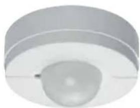
Close-up of a circular mechanical component with a central recess and a small protrusion (no text or symbols visible)EE880
Description Cat ref.
PIR Corridor Motion Detector EE880
Klik
Lighting Control Module
Klik LCM's (Lighting Control Module) enable the control of an area with up to 4 different control groups. Each group of outputs can control standard switched and/or digital dimmable (DALI/DSI) luminaires. The control module can be connected to up to 4 SELV occupancy sensors and up to 4 wall switch overrides (double retractive, centre off). Any switch or occupancy sensor can be assigned to any output.
The programming is carried out with iPad and communicates with the LCM via Bluetooth. We've also recently introduced an LCM which allows for local physical disconnection of bluetooth technology, for use in security sensitive applications.


SELV Switching / Dimming
Each channel is capable of being switched via one of 4 or more switch inputs.

Sensor with integral lux sensor (SELV)
This allows daylight dimming and switching utilising any natural light available

Scene setting
4 lighting scenes are possible (plus global Up/Down-On/Off) controlled via centre-off 2 pole retractive grid switch modules and 2 separate scene profiles are available.

Partition switch
This allows total and separate control of a room with a partition and switch fitted.

Corridor hold
Linking LCMs with RJ45 lead to hold designated corridor area

Bluetooth local disconnection
LCM references with BT suffix: Bluetooth function can be locally disconnected for enhanced security applications.

Integral emergency test timers
Emergency test carried out via an emergency test switch (can be set for up to 5 hours). Whilst on test the other luminaires will dim to a pre-set value.

Presence & absence sensing
Each output channel can be set to Presence or Absence individually.

Light level offset between channels
This function allows phasing channels to set as a percentage of the lead channel (e.g. 10%, 60%, 80%, 100%).

Three level timeout
At timeout, lighting can turn Off or Dim down in three stages.

Dimming - DSI, DALI (Broadcast)
Broadcast on the required channel to all connected luminaire
Lighting Control Module with KlikLink
Characteristics:
- The KLCM allows connection and control of multiple luminaires with four separate channels.
- Switching, dimming (DSI & DALI), corridor hold, partition switching, daylight switching & dimming, scene settings, integral emergency test times, reset profiles, light level offset (channel to channel).
- Setting up of KLCM is accomplished via KlikLink app, available on iOS for iPad.
- For technical data, see page 36
| Description | Cat ref. |
| 13 Way 4 Channel LCM Wire in, Plug out | KLCM413W |
| 13 Way 4 Channel LCM Wire in, Plug out, 230V EM Test Override | KLCM413WIET |
| 13 Way 4 Channel LCM Wire in, Plug out, with bluetooth disconnect switch | KLCM413WBT ★ |
| 13 Way 4 Channel LCM Wire in, Plug out, 230V EM Test Override, with bluetooth disconnect switch | KLCM413WETBT ★ |
| KlikLink iPad App (Free of charge) | Search KlikLink In |
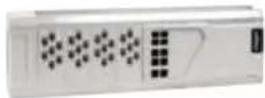
KLCM413W
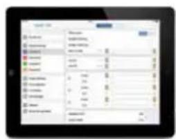
KlikLink App (Shown on iPad, not included)
Lighting Control Module Occupancy Sensors
Characteristics:
- Klik SELV LCM occupancy sensors come complete with a 10m RJ11 lead and have integrated daylight sensing.
- Sensing options are selected via the KlikLink app (e.g. presence/absence).
- KLCM-30S is designed for use as a corridor sensor.
- KLCM-5OS is designed for use as a whole room sensor.
| Description Range | Cat ref. | |
| Klik LCM Occupancy Sensor with 1 Sensor Head | 5m | KLCM-OS |
| Klik LCM Occupancy Sensor with 1 Sensor Head | 10m | KLCM-1OS |
| Klik LCM Corridor Sensor with 3 Sensor Heads | 15 x 5m | KLCM-3OS |
| Klik LCM Wide Area Sensor with 5 Sensor Heads | 15 x 15m | KLCM-5OS |

KLCM-OS

natural_image
Close-up of a ceiling-mounted air vent with a circular fan and mounting bracket (no text or symbols visible)KLCM-5OS
Lighting Control Module Switch Drop Leads (Grey)
Characteristics:
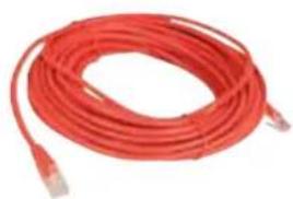
- RJ45 to switch (wire-in) lead available in a variety of lengths.
SELV. - Cables supplied standard with RJ45 plug on both ends.
Note: for retractive wall switch, please see below
Description Cat ref. Red Cat ref. Grey
RJ45 SELV Switch Drop Lead
5m KLO5RJ45R KLO5RJ45G
10m KLO10RJ45R KLO10RJ45G
15m KLO15RJ45R KLO15RJ45G
20m KLO20RJ45R KLO20RJ45G
30m KLO30RJ45R KLO30RJ45G
40m KLO40RJ45R KLO40RJ45G
50m KLO50RJ45R KLO50RJ45G
RJ45 Splitter KLORJ45CON

natural_image
Coiled white cable or wire with two connectors, no visible text or symbolsKLO15RJ45G
natural_image
Red cable with connectors, no visible text or symbolsKLO15RJ45R
User Controls
Characteristics:
- Our Sollysta grid retractive wall switches make the perfect user control companion to the LCM.
- Other grid finishes are available, please see our Wiring Accessories Catalogue for the full range.
Description Cat ref.
Sollsyta Grid Retractive Wall Switch
1 Gang Grid Plate WMGP1
1 Gang Grid Frame WMGF1
2 Way & Centre Off Retractive Wall Switch WMGS13R

WMGS13R

natural_image
White electronic device with four vertical slots and a label 'Klik' on the front panel (no readable text or symbols beyond branding)KLDS4

natural_image
Black rectangular electronic component with multiple slots and mounting holes (no visible text or symbols)KLDS6BLACK
Marshalling Boxes
Characteristics:
- Klik marshalling boxes are used in conjunction with Klik 3 and 4 pin plugs to connect luminaires within an area. The Klik marshalling box can be separated into two independently switched circuits. These circuits can be controlled via wall switch or occupancy sensor.
- Complies with BS 5733:2010.
- Main terminal rating: 16 Amps.
- Socket outlet rating: 6 Amps.
- Separate terminals for flexible conductors, rating: 10 Amps.
- Short circuit tested 1500A conditional rating.
- Socket outlets accept either Klik lighting (3 pin) plugs, Klik auxiliary (4 pin) plugs.
Description Cat ref.
4 Way Klik Lighting Distribution Unit KLDS4
6 Way Klik Lighting Distribution Unit KLDS6
8 Way Klik Lighting Distribution Unit KLDS8
10 Way Klik Lighting Distribution Unit KLDS10
12 Way Klik Lighting Distribution Unit KLDS12
6 Way Klik Lighting Distribution Unit - Black
KLDS6BLACK ★
natural_image
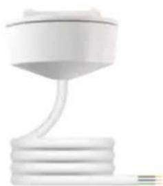
White plastic cup with a coiled tube, isolated on white background (no text or symbols)PCR2000/1.0
3 Pin Pre-wired 6A Plug-in Ceiling Rose
Characteristics:
- 6A pre-wired plug-in ceiling roses are used to connect luminaires to a fixed wiring installation.
- Complies with BS 6972 and BS 5733:2010.
- PVC flexible cord complies with BS EN 50525-2-11.
- Low smoke zero halogen flexible cord, complies with BS EN 50525-3-11.
- All leads have prepared ends.
Description Box Quantity PVC Cat ref. LSZH Cat ref.
6A Plug-in Ceiling Rose with 0.75mm² Flexible Cord
1 Metre 10 PCR2000/1.0 PCR2000/LSF/1.0
2 Metre 10 PCR2000/2.0 PCR2000/LSF/2.0
3 Metre 5 PCR2000/3.0 PCR2000/LSF/3.0
4 Metre 5 PCR2000/4.0 PCR2000/LSF/4.0
6A Plug-in Ceiling Rose with 1mm² Flexible Cord
2 Metre 10 PCR2000/1.0PVC/2 PCR2000/1.0LSF/2
3 Metre 5 PCR2000/1.0PVC/3 PCR2000/1.0LSF/3
4 Metre 5 PCR2000/1.0PVC/4 PCR2000/1.0LSF/4
5 Metre 5 PCR2000/1.0PVC/5 PCR2000/1.0LSF/5
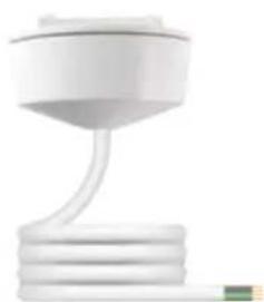
natural_image
White office lamp with a curved neck and base, no visible text or symbolsCR64AX/1.0
4 Pin (Including Auxiliary) Pre-wired 6A Plug-in Ceiling Rose
Characteristics:
- Auxiliary 6A pre-wired plug-in ceiling roses are used to connect luminaires to a fixed wiring installation.
- Complies with BS 6972 and BS 5733:2010.
- PVC flexible cord complies with BS EN 50525-2-11.
- Low smoke zero halogen flexible cord, complies with BS EN 50525-3-11.
- All leads have prepared ends.
| Description | Box Quantity | PVC Cat ref. LSZH Cat ref. | |
| 6A Pre-wired Ceiling Rose with 0.75mm ^2 Flexible Cord | |||
| 1 Metre | 10 | CR64AX/1.0 | CR64AX/LSF/1.0 |
| 2 Motre | 10 | CR64AX/2.0 | CR64AX/LSF/2.0 |
| 3 Metre | 5 | CR64AX/3.0 | CR64AX/LSF/3.0 |
| 4 Metre | 5 | CR64AX/4.0 | CR64AX/LSF/4.0 |
6A Pre-wired Ceiling Rose with 1mm² Flexible Cord
| 2 Metre | 10 | CR64AX/1.0PVC/2 | CR64AX/1.0LSF/2 |
| 3 Metre | 5 | CR64AX/1.0PVC/3 | CR64AX/1.0LSF/3 |
| 4 Metre | 5 | CR64AX/1.0PVC/4 | CR64AX/1.0LSF/4 |
| 5 Metre | 5 | CR64AX/1.0PVC/5 | CR64AX/1.0LSF/5 |
3 Pin Pre-wired 6A Plugs
Characteristics:
- 6A pre-wired plugs are used to connect luminaires to a Klik ceiling rose or marshalling box. All leads have prepared ends.
- Complies with BS 6972 and BS 5733:2010.
- PVC flexible cord complies with BS EN 50525-2-11.
- Low smoke zero halogen flexible cord, complies with BS EN 50525-3-11.
Description Quantity PVC Cat ref. LSZH Cat ref.
6A Pre-wired Plugs with 0.75mm² Flexible Cord
| 1 Metre 10 P22/1.0 P22/LSF/1.0 | ||
| 2 Metre 10 P22/2.0 P22/LSF/2.0 | ||
| 3 Metre 5 P22/3.0 P22/LSF/3.0 | ||
| 4 Metre 5 P22/4.0 P22/LSF/4.0 | ||
| 6A Pre-wired Plugs with 1mm^2 Flexible Cord | ||
| 2 Metre 10 P22/1.0PVC/2 P22/1.0LSF/2 | ||
| 3 Metre 5 P22/1.0PVC/3 P22/1.0LSF/3 | ||
| 4 Metre 5 P22/1.0PVC/4 P22/1.0LSF/4 | ||
| 5 Metre 5 P22/1.0PVC/5 P22/1.0LSF/5 | ||
4 Pin (Including Auxiliary) Pre-wired 6A Plugs - White
Characteristics:
- Klik auxiliary 6A pre-wired plugs are used to connect luminaires to a Klik ceiling rose or marshalling box.
- Complies with BS 6972 and BS 5733:2010.
- PVC flexible cord complies with BS EN 50525-2-11
- Low smoke zero halogen flexible cord, complies with BS EN 50525-3-11.
- All leads have prepared ends.
Description Quantity PVC Cat ref. LSZH Cat ref.
6A Pre-wired Plugs with 0.75mm² Flexible Cord
| 1 Metre 10 P64AX/1.0 P64AX/LSF/1.0 | |||
| 2 Metre 10 P64AX/2.0 P64AX/LSF/2.0 | |||
| 3 Metre 5 P64AX/3.0 P64AX/LSF/3.0 | |||
| 4 Metre 5 P64AX/4.0 P64AX/LSF/4.0 |
6A Pre-wired Plugs with 1mm² Flexible Cord
| 2 Metre 10 P64AX/1.0PVC/2 P64AX/1.0LSF/2 | ||
| 3 Metre 5 P64AX/1.0PVC/3 P64AX/1.0LSF/3 | ||
| 4 Metre 5 P64AX/1.0PVC/4 P64AX/1.0LSF/4 | ||
| 5 Metre 5 P64AX/1.0PVC/5 P64AX/1.0LSF/5 |
4 Pin (Including Auxiliary) Pre-wired 6A Plugs - Red
Characteristics:
- Klik auxiliary 6A pre-wired plugs are used to connect luminaires to a Klik ceiling rose or marshalling box.
- Complies with BS 6972 and BS 5733:2010.
- PVC flexible cord complies with BS EN 50525-2-11.
- Low smoke zero halogen flexible cord, complies with BS EN 50525-3-11.
- All leads have prepared ends.
Description Quantity PVC Cat ref. LSZH Cat ref.
6A Pre-wired Plugs with 0.75mm ^2 Flexible Cord
| 1 Metre | 10 | P64AXR/1.0 P64AXR/LSF/1.0 |
| 2 Motre | 10 | P64AXR/2.0 P64AXR/LSF/2.0 |
| 3 Metre | 5 | P64AXR/3.0 P64AXR/LSF/3.0 |
| 4 Motre | 5 | P64AXR/4.0 P64AXR/LSF/4.0 |
6A Pre-wired Plugs with 1mm² Flexible Cord
| 2 Metre 1.00mm ^2 Flexible Cord | 10 | P64AXR/1.0PVC/2 | P64AXR/1.0LSF/2 |
| 3 Metre 1.00mm ^2 Flexible Cord | 5 | P64AXR/1.0PVC/3 | P64AXR/1.0LSF/3 |
| 4 Metre 1.00mm ^2 Flexible Cord | 5 | P64AXR/1.0PVC/4 | P64AXR/1.0LSF/4 |
| 5 Metre 1.00mm ^2 Flexible Cord | 5 | P64AXR/1.0PVC/5 | P64AXR/1.0LSF/5 |

natural_image
White electrical plug with coiled cable and two terminal connectors (no text or symbols visible)P22/1.0

natural_image
White electrical plug with coiled cable and two terminal connectors (no text or symbols visible)P64AX/1.0

natural_image
Red and white electrical plug with coiled wire (no text or symbols visible)P64AXR/1.0

natural_image
White circular electronic device with a central knob and two mounting holes (no visible text or symbols)PCR2000
3 Pin Plug-in Ceiling Rose & Cover
Characteristics:
- The 6A plug-in ceiling rose is used to offer a pluggable connection for luminaires. The luminaire can be connected and disconnected under load.
- Complies with BS 5733:2010.
- Sockets have 4 terminations: line, neutral, CPC and loop-in.
- Plugs have 3 terminations: line, neutral and CPC.
- Fixing: 50.8mm Standard Diagonal (BESA)
Description Quantity Cat ref.
3 Pin Plug-in Ceiling Rose White 10 PCR2000
3 Pin Plug-in Ceiling Rose Black 10
PCR2000BLACK ★

natural_image
Two overlapping discs, one red and one white, showing no text or symbols.CR64AX/R
4 Pin (including Auxiliary) Plug-in Ceiling Rose & Cover
Characteristics:
- Klik 6A pre-wired plug-in ceiling roses are used to connect luminaires to a fixed wiring installation. Auxiliary contact available, a typical use is for emergency lighting.
- Complies with BS 6972 and BS 5733:2010.
- Sockets have 5 terminations: line, neutral, CPC, auxiliary and loop-in.
- Plugs have 4 terminations: line, neutral, CPC and auxiliary.
Description Quantity Cat ref.
4 Pin Plug-in Ceiling Rose White 10 CR64AX
4 Pin Plug-in Ceiling Rose Red 10 CR64AX/R

A1/R
Spare Ceiling Rose Cover
Description Quantity Cat ref.
Ceiling Rose Cover White 10 A1
Ceiling Rose Cover Red 10 A1/R
Ceiling Rose Cover Black 10
A1BLACK ★

natural_image
Pure electrical circuit lines without any symbolsP22
3 Pin Plug
Characteristics:
- Klik 3 pin plugs are used to connect into a Klik socket giving a pluggable connection to luminaires.
- Complies with BS 6972 and BS 5733:2010.
- Suitable for use with any Klik 3 or 4 pin socket.
- P22 plug is supplied in a plug-in ceiling rose, cat ref. PCR2000.
- Plugs have 3 terminations: line, neutral and CPC.
Warning: Plugs must not be fitted on the supply side of any installation - they must be connected to the load / fitting / appliance side of the installation.
Description Quantity Cat ref.
3 Pin Plug White 10 P22
3 Pin Plug Black
10
P22BLACK ★
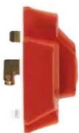
natural_image
Red plastic door panel with metal bracket (no text or symbols visible)P64AX/R
4 Pin (Including Auxiliary) Plug
Characteristics:
- Klik plugs with auxiliary pin are used to connect into the Klik sockets giving a pluggable connection to luminaires.
- Complies with BS 6972 and BS 5733:2010.
- Suitable for use with any Klik 4 pin sockets.
- P64AX plug is supplied in a plug-in ceiling rose, Cat. ref. CR64AX.
- Plugs have 4 terminations: line, neutral, CPC and auxiliary.
Warning: Plugs must not be fitted on the supply side of any installation - they must be connected to the load / fitting / appliance side of the installation.
Description Quantity Cat ref.
4 Pin Plug White 10 P64AX
4 Pin Plug Red
10 P64AX/R
3 Pin Plug Socket Outlets
Characteristics:
- 6A socket outlets are used in conjunction with 6A plugs to provide a pluggable connection to luminaires.
- Complies with BS 6972 and BS 5733:2010.
- Suitable for use with standard Klik 3 pin plug.
- S27 socket is supplied in plug-in ceiling rose, Cat. Ref. PCR2000.
- S27 socket will accept A1 cover.
- S26/TC socket is an S26 architrave socket pre-assembled with a trunking clamp.
Description Quantity Cat ref.
3 Pin Round Socket White 10 S27

natural_image
White circular socket with three slots and two holes, labeled 'klik' (no other text or symbols)S27
4 Pin (Including Auxiliary) Plug Socket Outlets
Characteristics:
- Klik auxiliary 6A socket outlets are used in conjunction with Klik auxiliary 6A plugs to provide a pluggable connection to luminaires.
- Complies with BS 6972 and BS 5733:2010.
- Suitable for use with standard Klik 4 pin plug.
- S64AX socket is supplied in plug-in ceiling rose, Cat. Ref. PCR2000.
- S64AX socket will accept A1 cover.
- S65AX socket is a square variant.
- All sockets have 5 terminations: line, neutral, CPC, auxiliary and loop-in.
- Can be used with Klik 3 or 4 pin plug.
Description Quantity Cat ref.
4 Pin Round Socket White 10 S64AX
4 Pin Round Socket Black 10
S64BLACK ★
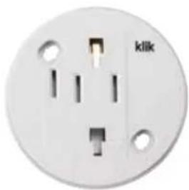
natural_image
White electrical socket with three slots and a label 'klik' on the side (no other text or symbols visible)S64AX

natural_image
Close-up of a black circular electronic component with internal components and mounting holes (no text or symbols visible)S64BLACK
Moulded Mounting Boxes
Description Quantity Cat ref.
Round Surface Box White 10 MB2
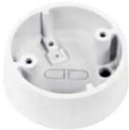
natural_image
White electrical outlet casing with visible circuit breakers and mounting holes (no text or symbols)MB2

natural_image
White ceiling-mounted recessed light fixture with adjustable lighting fixtures (no text or symbols visible)EEK513W
Occupancy Sensors with Remote Programming & Control Options
Characteristics:
- Comes complete with integral photocell and the facility for wall switch override.
- Can be programmed for absence or presence.
- Range 7m diameter for large movements, 5m diameter for small movements.
- Factory presets, lux = 400, time = 20 min, presence detection.
Description Cat ref.
Flush Mounted Standard Occupancy Sensor, Pre-Wired 3m EEK513W
Flush Mounted Standard Occupancy Sensor (without cable) EEK510B
Klik Occupancy Sensor 6 Amp Long Range KLOS6LR
Flush Mounted Standard Occupancy Sensor (without cable) - Black
EE815B ★

natural_image
Close-up of a black ceiling-mounted recessed lamp with adjustable lighting (no text or symbols visible)EE815B
natural_image
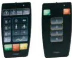
Two identical black-and-white photos of a mobile phone with control buttons and navigation icons (no visible text or symbols)EEK001 EEK002
Remote Controls for EEK Sensors Only
Characteristics:
- EEK001 programming tool is easy to use with 2 memory settings to enable repeatability.
- EEK002 remote control comes with a wall mounting bracket for storage and allows room occupant to have control of lighting output.
Description Cat ref.
Programming Tool EEK001
Remote Control EEK002
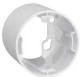
natural_image
White cylindrical mechanical component with internal cutouts (no text or symbols)EE005
Accessories
Description Cat ref.
Backbox for surface/conduit mounting of flush sensors EEK005
Backbox for surface/conduit mounting of flush sensors - Black
EEK005B ★
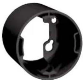
natural_image
Black plastic mechanical component with cutouts and mounting holes (no text or symbols)EEK005B
Occupancy Sensors
Characteristics:
- Adjustment achieved by potentiometer only
- Automatic switching of electric loads depending on heat motion and ambient brightness
- EE804A: Surface-mounted installation
- EE805A: Cavity/Flush installation (75mm hole diameter)
- Combination of presence and motion detector with enhanced detection sensitivity in the central presence-detection area
- Response brightness adjustable
- Delay time adjustable
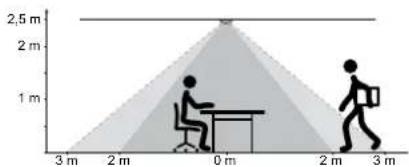
- Coverage 360 degrees, Diameter 6m @ 2.5m, (motion) enhanced detection area 4m Diameter (presence) @ 2.5m
- Factory presets: Lux = 200, Time = 3 Minutes
Description Cat ref.
Movement Detector 360" Surface Mounted EE804A
Movement Detector 360° Flush Mounted EE805A

natural_image
Circular white object with concentric rings, resembling a mechanical or architectural component (no text or symbols visible)EE804A
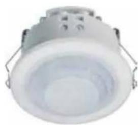
natural_image
Exterior view of a white ceiling-mounted recessed light fixture (no text or symbols visible)EE805A
Mounting Options for Trunking
Mounting Accessory can be clipped into the rear or top channel slot. It can be easily removed by inserting a screwdriver in the RELEASE slot.

Fixed Wiring Connection
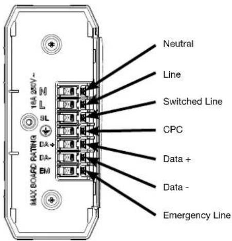
Klik 7 Pin LMB has seven screw terminals available to the installer and are arranged in the end cap as per diagram. DA+/DA- connections can be used for DALI/DSI control.

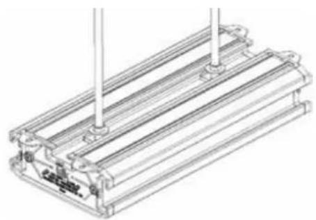
Mounting Options for Drop Rod (Lighting Marshalling Box)
Option 1.
Klik 7 Pin LMB features open ends to allow you to slide the box into position before tightening for easier installation, or push the box up on to the nut and rotate to locate and tighten to secure.

natural_image
Technical line drawing of an electrical enclosure or module with internal compartments and connections (no text or symbols)Option 2.
Single sided LMB can be mounted from the top as option 1 or from the rear as shown. Note: Double sided LMBs can only be mounted with option 1.
natural_image
Technical line drawing of a mechanical assembly with vertical rods and a base plate (no text or symbols)Mounting Options for Wall & Ceiling
Klik 7 Pin LMB includes the Klik mounting accessory, this makes it much easier to mount LMB with Nail Guns or traditional fixings. 2 accessories are included with each LMB. Mounting Accessory can be clipped into the rear or top channel slot. It can be easily removed by inserting a screwdriver in the RELEASE slot.
Note: Double sided LMB can only be mounted on top channel slot.

natural_image
Exploded view diagram of a battery pack assembly (no text or labels)Screw mounting tabs (x4)

flowchart
graph TD
    A["Module 1"] --> B["Component 1"]
    C["Module 2"] --> D["Component 2"]
    E["Module 3"] --> F["Component 3"]
    G["Module 4"] --> H["Component 4"]
    I["Module 5"] --> J["Component 5"]
    K["Module 6"] --> L["Component 6"]
    M["Module 7"] --> N["Component 7"]
    O["Module 8"] --> P["Component 8"]
    Q["Module 9"] --> R["Component 9"]
    S["Module 10"] --> T["Component 10"]
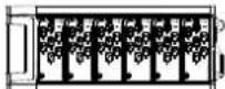
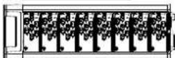
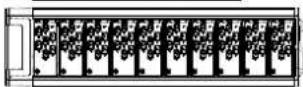
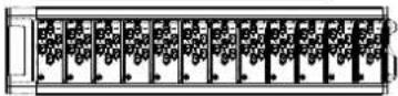
Lighting Marshalling Boxes (LMB) - Fixed Wiring
16A Rated LMB Complying to BS 5733:2010

KLMB4W
KLMB6W
KLMB8W
KLMB10W
KLMB12W

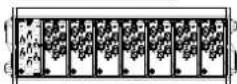
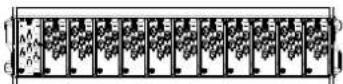
Lighting Marshalling Boxes (LMB) - Pluggable 16A Rated LMB Complying to BS 5733:2010

KLMB5P
KLMB7P
KLMB9P
KLMB11P


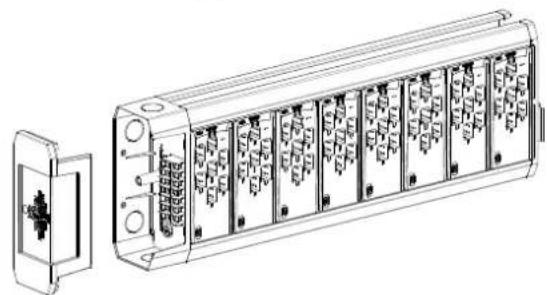
Dual Channel Lighting Marshalling Boxes (LMB) - Fixed Wiring
16A Rated LMB complying to BS 5733:2010
natural_image
Technical line drawing of a multi-chamber electronic device with internal components and a separate housing (no text or symbols visible)KLMB244W
KLMB255W
KLMB266W


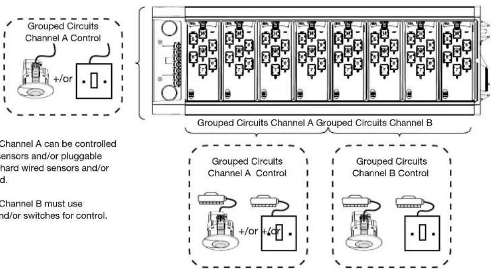
Grouped Circuits - Control
-
Grouped Circuits Channel A can be controlled by using pluggable sensors and/or pluggable switch. Alternatively hard wired sensors and/or switches can be used.
-
Grouped Circuits Channel B must use pluggable sensors and/or switches for control.
| Previous Part Reference | Description New Part | Reference | New Description |
| KLA/10/1-5P 16A Lighting Link Lead 10m 1.5mm 3 Core P-P | K7A10M15P ★ | 16A Lighting Link Lead 10m 1.5mm 3 Core P-P | |
| KLA/5/1-5P 16A Lighting Link Lead 5m 1.5mm 3 Core P-P | K7A5M15P ★ | 16A Lighting Link Lead 5m 1.5mm 3 Core P-P | |
| KLB/1/0-75W 16A Lighting Lead 1m 0.75mm 3 Core P-W | K7B1M075W ★ | 16A Lighting Lead 1.5m 0.75mm 3 Core P-W | |
| KLB/1/1W 16A Lighting Lead 1m 1mm 3 Core P-W | K7B1M1W ★ | 16A Lighting Lead 1.5m 1mm 3 Core P-W | |
| KLB/3/0-75W 16A Lighting Lead 3m 0.75mm 3 Core P-W | K7B3M075W ★ | 16A Lighting Lead 3m 0.75mm 3 Core P-W | |
| KLB/3/1W 16A Lighting Lead 3m 1mm 3 Core P-W | K7B3M1W ★ | 16A Lighting Lead 3m 1mm 3 Core P-W | |
| KLB/5/0-75W 16A Lighting Lead 5m 0.75mm 3 Core P-W | K7B5M075W ★ | 16A Lighting Lead 5m 0.75mm 3 Core P-W | |
| KLB/5/1W 16A Lighting Lead 5m 1mm 3 Core P-W | K7B5M1W ★ | 16A Lighting Lead 5m 1mm 3 Core P-W | |
| KLE/3/1-5W 16A Lighting Lead 3m 1.5mm 3 Core P-W | K7E3M15W ★ | 16A Lighting Lead 3m 1.5mm 3 Core P-W | |
| KLE/5/1-5W 16A Lighting Lead 5m 1.5mm 3 Core P-W | K7E5M15W ★ | 16A Lighting Lead 5m 1.5mm 3 Core P-W | |
| KLG/10/1-5P 16A Lighting Link Lead 10m 1.5mm 4 Core P-P | K7G10M15P ★ | 16A Lighting Link Lead 10m 1.5mm 4 Core P-P | |
| KLG/5/1-5P 16A Lighting Link Lead 5m 1.5mm 4 Core P-P | K7G5M15P ★ | 16A Lighting Link Lead 5m 1.5mm 4 Core P-P | |
| KLJ/1/0-75W 16A Lighting Lead 1m 0.75mm 4 Core P-W | K7J1M075W ★ | 16A Lighting Lead 1.5m 0.75mm 4 Core P-W | |
| KLJ/1/1W 16A Lighting Lead 1m 1mm 4 Core P-W | K7J1M1W ★ | 16A Lighting Lead 1.5m 1mm 4 Core P-W | |
| KLJ/3/0-75W 16A Lighting Lead 3m 0.75mm 4 Core P-W | K7J3M075W ★ | 16A Lighting Lead 3m 0.75mm 4 Core P-W | |
| KLJ/3/1-5P 16A Lighting Lead 3m 1.5mm 4 Core P-P | K7J3M15P ★ | 16A Lighting Lead 3m 1.5mm 4 Core P-P | |
| KLJ/3/1W 16A Lighting Lead 3m 1mm 4 Core P-W | K7J3M1W ★ | 16A Lighting Lead 3m 1mm 4 Core P-W | |
| KLJ/5/0-75W 16A Lighting Lead 5m 0.75mm 4 Core P-W | K7J5M075W ★ | 16A Lighting Lead 5m 0.75mm 4 Core P-W | |
| KLJ/5/1-5P 16A Lighting Lead 5m 1.5mm 4 Core P-P | K7J5M15P ★ | 16A Lighting Lead 5m 1.5mm 4 Core P-P | |
| KLJ/5/1W 16A Lighting Lead 5m 1mm 4 Core P-W | K7J5M1W ★ | 16A Lighting Lead 5m 1mm 4 Core P-W | |
| KLK/5/1-5P 16A Lighting Link Lead 5m 1.5mm 5 Core P-P | K7K5M15P ★ | 16A Lighting Link Lead 5m 1.5mm 5 Core P-P | |
| KLP/1/0-75W 16A Lighting Lead 1m 0.75mm 5 Core P-W | K7P1M075W ★ | 16A Lighting Lead 1.5m 0.75mm 5 Core P-W | |
| KLP/1/1-5W 16A Lighting lead 1m 1.5mm2 5 core P-W | K7P1M15W ★ | 16A Lighting lead 1.5m 1.5mm2 5 core P-W | |
| KLP/1/1W | 10A Lighting lead 1m 1mm2 5 core P-W | K7P1M1W ★ | 10A Lighting lead 1.5 1mm2 5 core P-W |
| KLP/3/0-75W 16A Lighting Lead 3m 0.75mm 5 Core P-W | K7P3M075W ★ | 16A Lighting Lead 3m 0.75mm 5 Core P-W | |
| KLP/3/1-5W 16A Lighting Lead 3m 1.5mm 5 Core P-W | K7P3M15W ★ | 16A Lighting Lead 3m 1.5mm 5 Core P-W | |
| KLP/3/1W | 16A Lighting Lead 3m 1mm 5 Core P-W | K7P3M1W ★ | 16A Lighting Lead 3m 1mm 5 Core P-W |
| KLP/5/0-75W 16A Lighting Lead 5m 0.75mm 5 Core P-W | K7P5M075W ★ | 16A Lighting Lead 5m 0.75mm 5 Core P-W | |
| KLP/5/1-5W 16A Lighting Lead 5m 1.5mm 5 Core P-W | K7P5M15W ★ | 16A Lighting Lead 5m 1.5mm 5 Core P-W | |
| KLP/5/1W | 16A Lighting Lead 5m 1mm 5 Core P-W | K7P5M1W ★ | 16A Lighting Lead 5m 1mm 5 Core P-W |
| KLT/1/0-75W 16A Lighting Lead 1m 0.75mm 6 Core P-W | K7T1M075W ★ | 16A Lighting Lead 1.5m 0.75mm 6 Core P-W | |
| KLT/1/1W | 16A Lighting Lead 1m 1mm 6 Core P-W | K7T1M1W ★ | 16A Lighting Lead 1.5m 1mm 6 Core P-W |
| KLT/3/0-75W 16A Lighting Lead 3m 0.75mm 6 Core P-W | K7T3M075W ★ | 16A Lighting Lead 3m 0.75mm 6 Core P-W | |
| KLT/3/1-5P | 16A Lighting Lead 3m 1.5mm 6 Core P-P | K7T3M15P ★ | 16A Lighting Lead 3m 1.5mm 6 Core P-P |
| KLT/3/1W | 16A Lighting Lead 3m 1mm 6 Core P-W | K7T3M1W ★ | 16A Lighting Lead 3m 1mm 6 Core P-W |
| KLT/5/0-75W 16A Lighting Lead 5m 0.75mm 6 Core P-W | K7T5M075W ★ | 16A Lighting Lead 5m 0.75mm 6 Core P-W | |
| KLT/5/1-5P | 16A Lighting Lead 5m 1.5mm 6 Core P-P | K7T5M15P ★ | 16A Lighting Lead 5m 1.5mm 6 Core P-P |
| KLT/5/1W | 16A Lighting Lead 5m 1mm 6 Core P-W | K7T5M1W ★ | 16A Lighting Lead 5m 1mm 6 Core P-W |
| KLTB/1/1-5W 16A T Connector 1m 1.5mm 3 Core P-W | K7B1M15WTEE ★ | 16A T Connector 1.5m 1.5mm 3 Core P-W | |
| KLTJ/1/1-5W 16A T Connector 1m 1.5mm 4 Core P-W | K7J1M15WTEE ★ | 16A T Connector 1.5m 1.5mm 4 Core P-W | |
| KLTP/1/1-5W | 16A T Connector 1m 1.5mm 5 Core P-W | K7P1M15WTEE ★ | 16A T Connector 1.5m 1.5mm 5 Core P-W |
| KLTT/1/1-5W 16A T Connector 1m 1.5mm 6 Core P-W | K7T1M15WTEE ★ | 16A T Connector 1.5m 1.5mm 6 Core P-W | |
| KLZ/3/1-5P | 16A Lighting Link Lead 3m 1.5mm 7 Core P-P | K7Z3M15P ★ | 16A Lighting Link Lead 3m 1.5mm 7 Core P-P |
| KLZ/5/1-5P | 16A Lighting Link Lead 5m 1.5mm 7 Core P-P | K7Z5M15P ★ | 16A Lighting Link Lead 5m 1.5mm 7 Core P-P |
KLPCR - Surface Mount Connector

PCR can be mounted in two ways, firstly on to conduit box or secondly direct on to a surface.

Terminating cables.
Terminal screws are retained in pockets.
Max Terminal Capacity 2x4mm ^2
Conductor strip length: 10mm.

K7PLUG Wireable Plug Configurations and Labels
Self Adhesive ID Labels:
Apply label for the type of lead you are making.
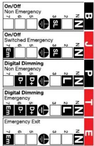
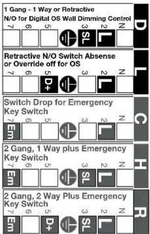
Lighting configurations for on / off and dimmable solutions.

Luminaire Connections Switch Drops Link Lead

EEK Sensors
Detection areas

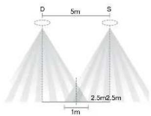
| H 2.5m | 3m 3.5m | |
| X 5m | 5m 5m | |
| Y 7m | 8m 9m |
Settings EEK513P/EEK515P
EEK523P/EEK525P


natural_image
Diagram of a mechanical device with a curved pipe and directional arrow, no text or symbols present
EE804A / EE805A Sensors
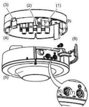
- Connecting terminals
- Mounting device locking screw
- Release opening
- Fastening grids
- Detector lens
- Response brightness potentiometer
- Potentiometer delay time
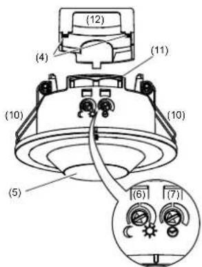
- Cover for potentiometer
- Locking screw
- Fixing springs
- Strain relief with mounting device for
cable ties - Cover for connection compartment
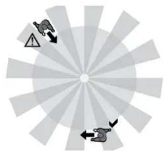
flowchart
graph TD
    A["Start"] --> B{Warning}
    B --> C["Action"]
    C --> D["End"]
Manual dimming with retractable switch (no OS)
Hager Sollysta retractable wall switch references
| Description | Cat ref. |
| 1 Gang Grid Plate WMGP1 | |
| 1 Gang Grid Frame WMGF1 | |
| 2 Way & Centre Off Retractive Wall Switch | WMGS13R |
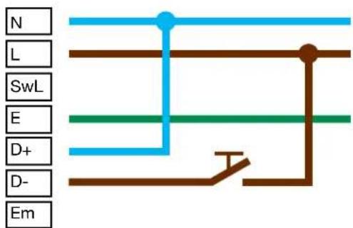
flowchart
graph TD
    N --> A
    L --> A
    SwL --> A
    E --> A
    D+ --> A
    D- --> A
    Em --> A
    A --> T
    style T stroke:#000,stroke-width:2px
Klik 7 Pin Product Standards
Product Description Klik Product identification BS number Description
| Klik 7 pin Marshalling Boxes | KLMB*W / P | BS 5733:2010 | General Requirements for Electrical Accessories. |
| Occupancy Sensor | EEK* | IEC 60669-1, IEC 60669-2-1 | Switches for household & similar fixed electrical installations Part 2-1 for Electronic switches. |
| Conduit Box / Surface Connector | KLPCR/7 | BS 5733:2010 | General requirements for Luminaire supporting couplers for domestic, light industrial & commercial use. |
| Luminaire Leads | K7B*, K7J*, K7P*, K7T* | BS 5733:2010 BS EN 61535 | Thermosetting insulated & thermoplastic sheathed cables for voltages up to & including 450 / 750 V for electric power & lighting & having low emission of smoke & corrosive gases when affected by fire. |
| LSOH Flexible Cord | Supplied with luminaire lead | BS 6500:2000 BS 7211:2012 | Thermosetting insulated & thermoplastic sheathed cables for voltages up to & including 450 / 750 V for electric power & lighting & having low emission of smoke & corrosive gases when affected by fire. |
Klik 4 Pin Product Standards
Product Description Klik Product identification BS number Description
| Klik Distribution Boxes | KLDSKLMB | BS 5733:2010 General requirements for Electrical Accessories | |
| Occupancy Sensor EEK*W | BS EN 60669-1,BS EN 60669-2-1 | Switches for household & similar fixed electrical installations Part 2-1 for Electronic switches. | |
| Mounting Boxes MB BS 5733:2010 General requirements for Electrical Accessories | |||
| Klik Ceiling Roses, Plugs,Outlets & Pre-Wired Leads | S, P, PCR | BS 5733:2010BS 6972:1988 | General requirements for Electrical AccessoriesGeneral requirements for Luminaire supporting couplers for domestic, light industrial & commercial useInstallation couplers intended for permanent connection in fixed installations |
| PVC Flexible Cord PVC BS 6500:2000 | Thermosetting insulated & thermoplastic sheathed cables for voltages up to & including 450 / 750 V for electric power & lighting & having low emission of smoke & corrosive gases when affected by fire. | ||
| LSF Flexible Cord LS0H | BS 6500:2000BS 7211:1998 | Thermosetting insulated & thermoplastic sheathed cables for voltages up to & including 450 / 750 V for electric power & lighting & having low emission of smoke & corrosive gases when affected by fire. | |
Product Materials
Klik plugs and sockets feature solid brass terminals and phosphor bronze contacts for good conductivity. Moulded components are manufactured from high quality thermoplastics.
Klik Terminal Capacities
Number of Conductors
| 0.75mm^2 | 1.0mm^2 | 1.5mm^2 | 2.5mm^2 | 4.0mm^2 | |
| Socket Outlets | - | 5 | 4 | 3 | 2 |
| Plugs P22, P64X, K7PLUG | 1 | 1 | 1 | - | - |

natural_image
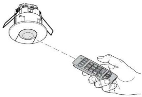
Line drawing of a hand holding a remote control with a ceiling-mounted device (no text or symbols)
The acknowledgment LED blinks during the sending of the IR message.
Technical specification
Power supply: 1x 3V CR2032 Shelf life of battery: 2½ years Protection index: IP 30
Use
The remote control allows the user to set or modify presence detector settings. When the potentiometer is on auto test it allows single and multiple settings.
The SET key is used to send the IR messages to the occupancy sensors. Multiple settings can be stored in Memo 1 and Memo 2 and re-called to set several devices.
Single setting
Example: reset


Multiple settings
Define the parameters to be changed and press SET to send.
Example: for 25 minutes and corridor use, press 20°, 5° and corridor.

In the case of 2 opposite states the green LED denotes ON and red LED denotes OFF (except Presence / Absence).
When no function is selected all LED's are OFF.
Settings available
| Key Meaning Indication | Function | ||
 | Presence Green LED on Presence on (automation mode) | ||
| Absence Red LED on Absence on (semi automatic mode) | |||
 | Power Up Green LED on The light is automatically switched on for 30 seconds after power up | ||
| Red LED on During warm up phase, the light output is off | |||
| Reset | Reset LED on To return to factory settings (Lux = 400, time = 20 min, presence on, power up off and cell active) | ||
| Test | Test LED on To validate the detection area | ||
| 8 | Time | LED on To set the time | It is possible to add times together e.g. press 2' and 5' for a time value of 7' |
 | Day level 1000 Lux | LED on To set the value to 1000 Lux | |
 | Learn | LED on To learn the current Lux level | |
| [2YAT] | Corridor 200 Lux | LED on To set the value to 200 Lux | |
 | Office 400 Lux | LED on To set the value to 400 Lux | |
| [S4AT] | Lux + | LED on To increase the Lux level (+100) | |
| Lux - | LED on To decrease the Lux level (-100) | ||
| [TICK] | Active cell | Green LED on The light is continuously measured | |
| Passive cell | RED LED on | The sensor will not switch the light off even if the ambient luminosity is sufficient | |
| Memo and set Key | Meaning Indication Function | ||
| Memo 1 | Press | LED is on until a setting is changed | To load/unload Memo 1 |
| Long press | LED is on for 5s, then will blink until released. After release, the LED goes off in case of setting change | To save the current setting as Memo 1 | |
| Memo 2 | Press | LED is on until a setting is changed | To load/unload Memo 2 |
| Long press | LED is on for 5s, then will blink until released. After release, the LED goes off in case of setting change | To save the current setting as Memo 2 | |
| SET | Short press (<5s) | LED flashes | To send an IR message of the current setting |
| Long press (>5s but <10s) only available if no setting active | LED blinks until release press | To toggle automatic mode on DALI/DSI | |

Use
The remote control allows the user to set or modify settings on the presence detectors EEK513W and EEK510B.
Each button corresponds to a command.

The acknowledgment LED blinks during the sending of the IR message.
Technical specification
Power supply: 1x 3V CR2032
Shelf life of battery: 3½ years
Protection index: IP 30
Settings available
| Key Action Function Product Type | |||
| on + | Short Press (< 5s.) On EEK513W / EEK510B | ||
| Long Press (> 5s.) Dim up EEK513W / EEK510B | |||
| off _ | Short Press Off EEK513W / EEK510B | ||
| Long Press (> 5s.) Dim down EEK513W / EEK510B | |||
| 1 | Short Press To start scene 1 | ||
| 2 | Short Press To start scene 2 | ||
| 3 | Short Press To start scene 3 | ||
| 4 | Short Press To start scene 4 | ||
Fixing Methods

natural_image
Technical line drawings of three different electronic device modules (no text or symbols visible)Drop Rods Direct: e.g. nail gun or screw fixing
(Not possible for plug-in KLCM412P)
(not possible for hard-wire KLCM413W)
Switch inputs - 1 to 4 (retractive wall switch ref: WMGS13R) Emergency test in & out
| Orange/White Scene 1 | Orange/White | Override - All Outputs On |
| Orange Scene 2 | Orange | Override - All Outputs Off |
| Green/White Scene 3 | Green/White | Corridor Hold Line |
| Blue Scene 4 | Blue | Emergency Test (Timer 1) |
| Brown/White On/Dim Up | Blue/White | Emergency Test (Timer 2) |
| Blue/White Off/Dim Down | Green | Emergency Test (Timer 3) |
| Brown 0V (Common) | Brown | Common |
| Green 12V (Not Used, must not be connected.) | Brown/White | Not Used. |
Occupancy Sensor Technical Characteristics
| Technical Characteristics | KLCM-OS | KLCM-1OS | KLCM-3OS | KLCM-5OS |
| Supply Voltage | 12V DC | SELV (12VDC) | SELV (12VDC) | SELV (12VDC) |
| Detection Area | Motion area: diameter 6m (product installed at 21⁄2m height) presence area: diameter 6m (product installed at 21⁄2m height) | 360° 10m | 360° 5m to 15m | 360° 15m |
| Receiver Class | 2 | 2 | 2 | 2 |
| Parasitic Power | .672mW | .672mW | 1.044mW | |
| Duration of lighting output operation | Via KlikLink App & LCM | Via KlikLink App & LCM | Via KlikLink App & LCM | Via KlikLink App & LCM |
| Luminocity threshold | Via KlikLink App & LCM | Via KlikLink App & LCM | Via KlikLink App & LCM | Via KlikLink App & LCM |
| Recommended installation height | 2.5m | 2.5m | 2.5m | 2.5m |
| Operating temperature | -20°C to +60°C | -20°C to +50°C | -20°C to +50°C | -20°C to +50°C |
| Storage temperature | -2-C to +70°C | -35°C to +70°C | -35°C to +70°C | -35°C to +70°C |
| Insulation class | II | II | II | II |
| Protection rating | IP41 | IP41 | IP41 | IP41 |
| Standards | BS EN 55015:2013 | BS EN55015:2013, BS EN61547:2009 | BS EN55015:2013, BS EN61547:2009 | BS EN55015:2013, BS EN61547:2009 |
| Maximum installation altitude | 2000m | 2000m | 2000m | 2000m |
| Polution degree | 2 | 2 | 2 | 2 |
| Connection | RJ11 | RJ11 6P4C | RJ11 6P4C | RJ11 6P4C |
| Dimensions | High: 70mm, Diameter: 101mm | High: 70mm, Diameter: 101mm | High: 70mm, Diameter: 101mm | |
| Weight | 110 grams | 110 grams | 110 grams | |
| Mounting hole diameter | 85mm | 85mm | 85mm |

Up to 4 sensor inputs per LCM (part ref: KLCM-OS)
Up to 4 switch inputs per LCM

- Plug-in sensor and switch control
- Any port can be configured via the KlikLink App.
- Grouping LCMs via RJ45 leads for corridor hold and groups for emergency test
- Programmed via the KlikLink app. Download from the App Store.
Wiring accessories from the Sollysta Grid range
| Centre off retractive switch module WMGS13R | |
| White moulded Grid Plates WMGPx (1,2,3 | 4,6 & 8) G |
| Grid Frames WMGFx (1,2 & 3/4) G | |
Technical Characteristics
| Number of channels 4 | ||||
| Number of outputs per channel 3 (hard wired LCM has 4 outputs on channel A) | ||||
| Number of sensor inputs 4 (KLCM-OS 10S / 30S / 50S) | ||||
| Number of switch inputs 4 | ||||
| Supply Voltage 230V AC 50Hz | ||||
| Rated current 10A (total load) | ||||
| Rated current each connector | 10A | |||
| Complies with | BS 5733:2010,BS EN 60669-2-5BS EN 61535:2009 - (Excluding clauses 10.1 and 10.3 due to Aluminium enclosure) | |||
| IP protection | IP20 | |||
| Connection for programming | Bluetooth Smart (Bluetooth 4) (only available on Apple iPad) | |||
| Dimensions | Height 145mm | Width 440mm | Depth 58mm | Weight 1.9kg |
Supply input connection Pluggable
Hard wired


natural_image
Technical line drawing of a mechanical or electrical component with multiple connectors and wiring (no text or symbols)
- Connecting the supply lead: plug in and push down
- Disconnecting the supply lead: press button and push up.
Plug colour coding
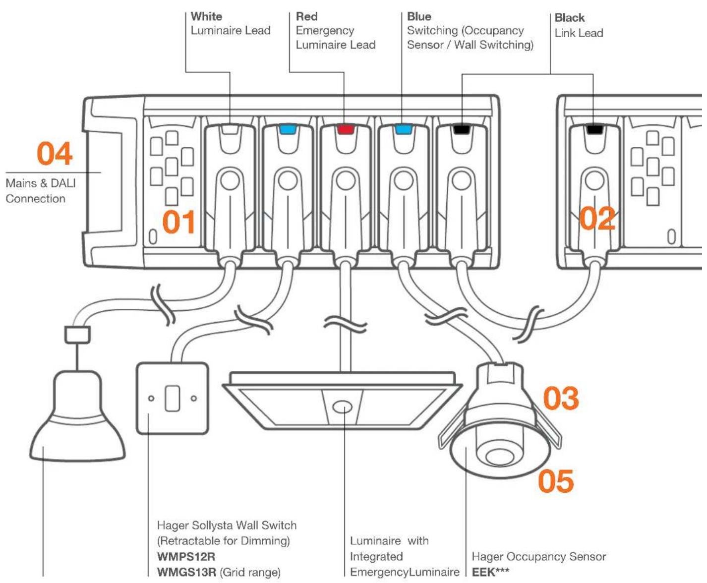
White: Luminaire Lead
Red: Luminaire & Emergency
Black: Link Lead
Klik 4
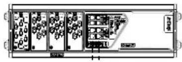
 + 3m Lead, Flush Mount + 3m Lead, Flush Mount |  Wireable, FlushMount Klik 4 Direct Plug-In Wireable, FlushMount Klik 4 Direct Plug-In |  |  Wireable, SurfaceMount Wireable, SurfaceMount | 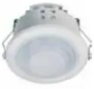 Wireable, FlushMount Wireable, FlushMount | |
| Technical characteristics EEK513W | EEK510B/EE815B KLOS | S6LR EE804A EE805A | |||
| Supply voltage | 230V- 50Hz | 230V- 50Hz | 230V - 50Hz | 230V - 50Hz | 230V - 50Hz |
| Detection type | Presence | Presence | Presence | Motion / Presence | Motion / Presence |
| Parasitic power | 270mW | 270mW | - | 0.3W | 0.3W |
| Detection (Length) | 7m | 7m | 25m | 6m | 6m |
| Detection (Width) | 7m | 7m | - | 6m | 6m |
| Detection angle | 360° | 360° | 6-18° | 360° | 360° |
| Detection frequency | - | - | - | - | - |
| Receiver class | - | - | - | - | - |
| Standby consumption | 2.4VA/270mW | 2.4VA/270mW | - | - | - |
| Duration of lighting output operation(S1) | 1min to 1hour | 1min to 1hour | 10 Secs to 40 Mins | 5s - 30min | 5s - 30min |
| Duration of time delay (S2) | - | - | - | - | - |
| Luminosity threshold | 5 to 1000 Lux | 5 to 1000 Lux | 30 Lux | 5 - 1000 | 5 - 1000 |
| Recommended installation height | 2.5m | 2.5m | 2.5m | 2.5m | 2.5m |
| Operating temperature | -10°C to +45°C | -10°C to +45°C | - | -5 - +45 | -5 - +45 |
| Storage temperature | -20°C to +60°C | -20°C to +60°C | - | -25 - +70 | -25 - +70 |
| Insulation class | II | II | - | 11 | 11 |
| Protection rating | IP41 | IP41 | IP20 | IP21 | IP21 |
| Standards | BS EN 60669-1BS EN 60669-2-1 | BS EN 60669-1BS EN 60669-2-1 | - | ||
| Pollution degree | 2 | 2 | - | ||
| Connection stranded | 0.5mm2 to 1.5mm2 | 0.5mm2 to 1.5mm2 | - 1mm - 2.5mm | 1mm - 2.5mm | |
| Connection solid | 0.5mm2 to 1.5mm2 | 0.5mm2 to 1.5mm2 | - 1mm - 2.5mm | 1mm - 2.5mm | |
| Switching channel | 1 | 1 | 1 | 1 | 1 |
| Lighting loads 230V~ AC1 | 16A | 16A | 6A | 10A | 10A |
| Switching capacity (Incandescent) | 2300W | 2300W | 1500W | 2300W | 2300W |
| Halogen lamps LV | - | - | - | ||
| Halogen ELV (12 or 24V) viaferromagnetic or electronictransformer | 1500W | 1500W | - 2300W | 2300W | |
| Compact fluorescent | 23 X 23W | 23 X 23W | 1500W Max | 20 x 20W | 20 x 20W |
| LED | 20 X20W | 20 X20W | 500W Max | 20 x 20W | 20 x 20W |
| Parallel compensated fluorescenttubes | 1000W | 1000W | 500W Max | 1000W | 1000W |
| Fluorescent tubes non-compensated | 1000W | 1000W | - | 1000W | 1000W |
| Electronic ballast | - | - | 750W- | 1000W | 1000W |
| DSI/DALI ballast | - | - | - | - | - |
| Remote programming | EEK001 | EEK001 | - | - | - |
| Remote control | EEK002 | EEK002 | - | - | - |
| Adjustable shutters (supplied) | x | x | x | x | x |
| Dimensions (L*W*H) | 80 x 80 x 70mm | 80 x 80 x 70mm | 80 x 80 x 50mm | ø 100 x 50mm | ø 90 x 61mm |
 |  |  |  |  | 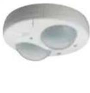 |
| On / Off, Plug-In Flush, 3m / 5m | Digital, Plug-In Flush, 3m / 5m | Digital, Wireable, Flush | Wireable, Surface Mount, Corridor | Mount, Hyper Frequency | Wireable, Semi-Recessed, 1 / 2 Channel |
| EEK513PEEK515P | EEK523PEEK525P | EEK520B EE880 EE883 | EE810 / EE811 | ||
| 230V- 50Hz | 230V- 50Hz | 230V- 50Hz | 230V- 50Hz | 230V- 50Hz | 230V- 50Hz |
| Presence | Presence | Presence | Motion | Motion | Presence |
| 60mW | 60mW | 60mW | 1W | 1W | 1.2W |
| 7m | 7m | 7m | 20m | 1m to 8m | 15.5m |
| 7m | 7m | 7m | 4m | 1m to 8m | 8m |
| 360^a | 360^o | 360^o | 360^o | 360^o | 360^o |
| - | - | - | - | 5.8 Ghz ± 0.075 Ghz | - |
| - | - | - | - | 2 | - |
| 60mW | 60mW | 60mW | 1W | 1W | 1.2W |
| 1min to 1hour | 1min to 1hour | 1min to 1hour | 5sec to 15 min | 5sec to 15 min | 1min to 30min |
| - | - | - | - | - | 30sec to 60min |
| 5 to 1000 Lux | 5 to 1000 Lux | 5 to 1000 Lux | 2 to 2000 lux | 2... 2000 lux | 5 to 1200Lux |
| 2.5m | 2.5m | 2.5m | 3 m | 2.5 m | 3 m |
| -10°C to +45°C | -10°C to +45°C | -10°C to +45°C | 20°C to +50°C | 20°C to +50°C | 0°C to +45°C |
| -20°C to +60°C | -20°C to +60°C | -20°C to +60°C | 35°C to +70°C | 35°C to +70°C | 10°C to +60°C |
| II | II | II | II | II | II |
| IP41 | IP41 | IP41 | IP54 | IP54 | IP41 |
| BS EN 60669-1BS EN 60669-2-1 | BS EN 60669-1BS EN 60669-2-1 | BS EN 60669-1BS EN 60669-2-1 | BS EN 60669-1BS EN 60669-2-1 | BS EN 60669-2-1EN 300 440-1 V1.3.1 | BS EN 60669-1BS EN 60669-2-1 |
| 2 | 2 | 2 | 2 | 2 | 2 |
| ^2 to 1.5mm ^2 | 0.5mm ^2 to 1.5mm ^2 | 0.5mm ^2 to 1.5mm ^2 | Max 1.5mm ^2 | Max 1.5mm ^2 | 1mm ^2 to 4mm ^2 |
| ^2 to 1.5mm ^2 | 0.5mm ^2 to 1.5mm ^2 | 0.5mm ^2 to 1.5mm ^2 | Max 1.5mm ^2 | Max 1.5mm ^2 | 1mm ^2 to 4mm ^2 |
| 1 | 1 | 1 | 1 | 1 | 1 |
| - | - | - | 10A | 10A | 16A |
| - | - | - | 2300W | 2300W | 2300W |
| - | - | - | 2300W | 2300W | - |
| - | - | - | 1500VA | 1500VA | 1500W |
| - | - | - | 20 x 20W | 20 x 20W | 20 X 18W |
| - | - | - | 20 x 20W | 20 x 20W | 20 X 18W |
| - | - | - | 1000W/C=110μf | 1000W/C=110μf | 290W/C=32μf |
| - | - | - | 1200W | 1200W | - |
| - | - | - | 580W | 580W | 1000W |
| Yes (24) | Yes (24) | Yes (24) | - | - | - |
| EEK001 | EEK001 | EEK001 | × | × | × |
| EEK002 | EEK002 | EEK002 | × | × | × |
| × | × | × | × | × | × |
| 80 x 80 x 70mm | 80 x 80 x 70mm | 80 x 80 x 70mm | 125 x 125 x 60mm | 110 x 110 x 70mm |
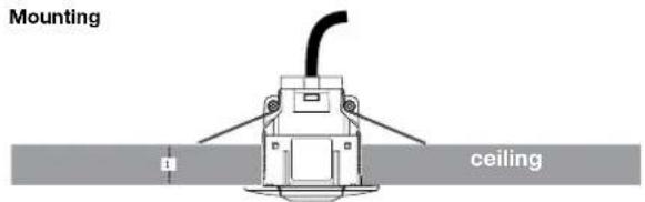
Mounting Methods
- Hanging from ceiling suspension system with Caddy Clips™
- Direct fixing to lighting trunking
- Direct fixing to ceiling or wall with No. 8 screws

Drop rods on sides Screw to surface Drop rods on rear

natural_image
Exterior view of a white industrial electrical cabinet with multiple panel slots and overhead wires (no visible text or symbols)
natural_image
Electrical cabinet with four switches and a battery unit (no visible text or symbols)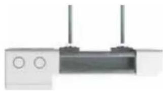
natural_image
Exterior view of a modern office building (no signage)Local Lighting Switch Control
Permanent emergency feed
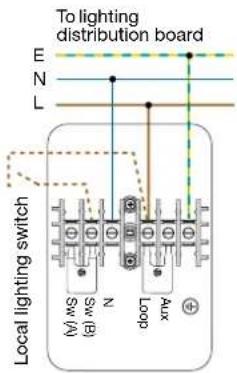
Local Lighting Switch Control
Centralised emergency test via key switch

Zone Lighting Control
Local emergency test control
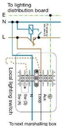
All ways switched by a single Hager EEK513W occupancy sensor

Switch wire to be connected as required.
Connected directly to a single luminaire
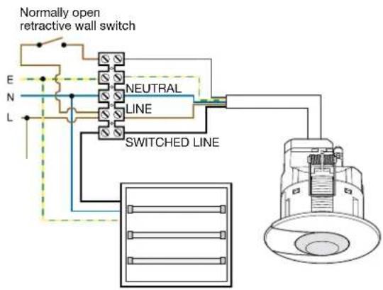

- Strip cable as above - Note: Trim cable tails to double over for better terminal contact.
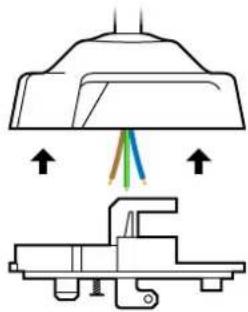
natural_image
Diagram showing a mechanical assembly with arrows indicating direction (no text or symbols present)- Remove plug cover.
- Pass cable through plug cover centre hole.

- Terminate conductors into terminals.
- Push outer sheath of cable firmly into jaws of sheath grip, making sure that at least 2mm of sheath protrudes below the grip.
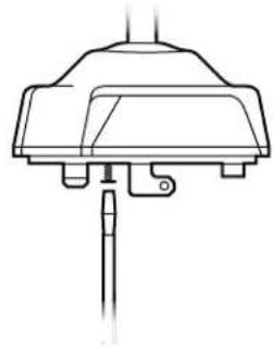
natural_image
Technical line drawing of a mechanical component or bracket (no text or symbols)- Refit cover.
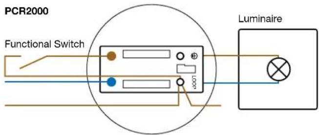
Note: earth connections omitted for clarity


:hager
Hager Ltd.
Hortonwood 50
Telford
Shropshire
TF1 7FT
Customer Contact Centre: 01952 675612
Technical Helpline: 01952 675689
hager.com/uk
sales@hager.co.uk
technical@hager.co.uk
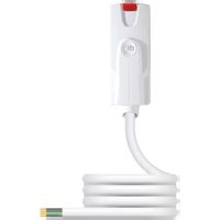
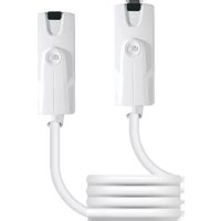
- Klik Lighting Connection
- Klik is the lighting connection system for all your lighting designs.
- From Start to Finish.
- Install
- Use
- Adapt
- What Klik can do for you
- Benefits - At a Glance
- Safe on-load connection
- 0301
- Electro Mechanical Connection
- Occupancy Sensing
- 04
- DALI Control
- 05
- Trimming of lux level
- 06
- Daylight Link
- A Fast, Adaptable & Secure Solution.
- The Value of Control
- Application Examples
- Klik 7
- Klik 4
- Lighting Connection
- Marshalling Boxes - Wire In, Plug Out
- Characteristics:
- Marshalling Box, Single Supply, Wire In, Plug Out
- Marshalling Box, Dual Channel, Wire In, Plug Out
- Marshalling Boxes - Plug In, Plug Out
- Marshalling Box, Single Supply, Plug In, Plug out
- Klik 7 Pre-wired Plugs with Sockets
- Pre-wired Plugs and Sockets for Standard Luminaires
- Pre-wired Plugs and Sockets for Standard Luminaires with Emergency
- Pre-wired Plugs and Sockets for Dimmable Luminaires
- Pre-wired Plugs and Sockets for Dimmable Luminaires with Emergency
- Klik 7 Pre-wired Plugs
- Pre-wired Plugs for Standard Luminaires
- Pre-wired Plugs for Standard Luminaires with Emergency
- Pre-wired Plugs for Emergency Exit Luminaires
- Klik 7 Pre-wired Plugs for Dimmable Luminaires
- Pre-wired Plugs for Dimmable Luminaires
- Pre-wired Plugs for Dimmable Luminaires with Emergency
- Klik 7 Pre-wired Marshalling Box Link Leads
- Pre-wired Link Leads - L, N, CPC
- Pre-wired Link Leads - L, N, CPC, Emergency
- Pre-wired Link Leads - L, N, SL, CPC, Emergency
- Pre-wired Link Leads - CPC, DA+, DA-
- Pre-wired Link Leads - L, N, SL, CPC, DA+, DA-, Emergency
- Ceiling Roses
- Wireable / Rewireable Plug
- Occupancy Sensors with Remote Programming & Control Options
- Semi-Recessed Occupancy Sensor
- Hyper Frequency Detector
- Features
- Corridor Motion Detector
- Klik
- Lighting Control Module
- SELV Switching / Dimming
- Sensor with integral lux sensor (SELV)
- Scene setting
- Partition switch
- Corridor hold
- Bluetooth local disconnection
- Integral emergency test timers
- Presence & absence sensing
- Light level offset between channels
- Three level timeout
- Dimming - DSI, DALI (Broadcast)
- Lighting Control Module with KlikLink
- Lighting Control Module Occupancy Sensors
- Lighting Control Module Switch Drop Leads (Grey)
- RJ45 SELV Switch Drop Lead
- User Controls
- Sollsyta Grid Retractive Wall Switch
- Marshalling Boxes
- Pin Pre-wired 6A Plug-in Ceiling Rose
- 6A Plug-in Ceiling Rose with 0.75mm² Flexible Cord
- 6A Plug-in Ceiling Rose with 1mm² Flexible Cord
- Pin (Including Auxiliary) Pre-wired 6A Plug-in Ceiling Rose
- Pin Pre-wired 6A Plugs
- Pin (Including Auxiliary) Pre-wired 6A Plugs - White
- Pin (Including Auxiliary) Pre-wired 6A Plugs - Red
- Pin Plug-in Ceiling Rose & Cover
- Pin (including Auxiliary) Plug-in Ceiling Rose & Cover
- Spare Ceiling Rose Cover
- Pin Plug
- Pin (Including Auxiliary) Plug
- Pin Plug Socket Outlets
- Pin (Including Auxiliary) Plug Socket Outlets
- Moulded Mounting Boxes
- Remote Controls for EEK Sensors Only
- Accessories
- Occupancy Sensors
- Mounting Options for Trunking
- Fixed Wiring Connection
- Mounting Options for Drop Rod (Lighting Marshalling Box)
- Option 1.
- Option 2.
- Mounting Options for Wall & Ceiling
- K7PLUG Wireable Plug Configurations and Labels
- Self Adhesive ID Labels:
- Product Materials
- Technical specification
- Use
- Single setting
- Multiple settings
- Mounting Methods
- Local Lighting Switch Control
- Zone Lighting Control
- :hager
Brand : HAGER
Model : K7P3M075WPCR
Category : Lighting