
TH-65PF9UK - Screen PANASONIC - Free user manual and instructions
Find the device manual for free TH-65PF9UK PANASONIC in PDF.


| Product Type | Professional Plasma Display |
| Screen Size | 65 inches (diagonal) |
| Resolution | 1920 x 1080 (Full HD) |
| Aspect Ratio | 16:9 |
| Contrast Ratio | 5,000,000:1 (dynamic) |
| Brightness | 1,500 cd/m² |
| Dimensions (without stand) | 1550 x 910 x 95 mm |
| Weight (without stand) | Approximately 45 kg |
| Power Consumption (typical) | 500 W |
| Standby Power Consumption | < 1 W |
| Video Inputs | HDMI x2, DVI-D x1, VGA (D-Sub) x1, Composite, Component |
| Control Input | RS-232C, LAN (RJ45) |
| Features | High brightness, anti-glare coating, 24/7 operation capable |
| Cleaning Instructions | Wipe gently with a soft, dry cloth; do not use liquid cleaners |
| Safety | Designed for wall mount or optional stand; ensure stable installation |
| Spare Parts | Available through Panasonic authorized service centers |
| Repairability | Professional service recommended; replaceable power supply and main board |
Frequently Asked Questions - TH-65PF9UK PANASONIC
User questions about TH-65PF9UK PANASONIC
0 question about this device. Answer the ones you know or ask your own.
Ask a new question about this device
Download the instructions for your Screen in PDF format for free! Find your manual TH-65PF9UK - PANASONIC and take your electronic device back in hand. On this page are published all the documents necessary for the use of your device. TH-65PF9UK by PANASONIC.
USER MANUAL TH-65PF9UK PANASONIC
Panasonic®
Operating Instructions
The illustration shown is an image.
Before connecting, operating or adjusting this product, please read these instructions completely.
Please keep this manual for future reference.
WARNING: To reduce the risk of electric shock, do not remove cover or back. No user-serviceable parts inside. Refer servicing to qualified service personnel.

The lightning flash with arrow-head within a triangle is intended to tell the user that parts inside the product are a risk of electric shock to persons.

The exclamation point within a triangle is intended to tell the user that important operating and servicing instructions are in the papers with the appliance.
WARNING: To prevent damage which may result in fire or shock hazard, do not expose this apparatus to rain or moisture. Do not place containers with water (flower vase, cups, cosmetics, etc.) above the set. (including on shelves above, etc.)
WARNING: 1) To prevent electric shock, do not remove cover. No user serviceable parts inside. Refer servicing to qualified service personnel. 2) Do not remove the grounding pin on the power plug. This apparatus is equipped with a three-pin grounding-type power plug. This plug will only fit a grounding-type power outlet. This is a safety feature. If you are unable to insert the plug into the outlet, contact an electrician. Do not defeat the purpose of the grounding plug.

Important Safety Instructions
1) Read these instructions.
2) Keep these instructions.
3) Heed all warnings.
4) Follow all instructions.
5) Do not use this apparatus near water.
6) Clean only with dry cloth.
7) Do not block any ventilation openings. Install in accordance with the manufacturer's instructions.
8) Do not install near any heat sources such as radiators, heat registers, stoves, or other apparatus (including amplifiers) that produce heat.
9) Do not defeat the safety purpose of the polarized or grounding-type plug. A polarized plug has two blades with one wider than the other. A grounding type plug has two blades and a third grounding prong. The wide blade or the third prong are provided for your safety. If the provided plug does not fit into your outlet, consult an electrician for replacement of the obsolete outlet.
10) Protect the power cord from being walked on or pinched particularly at plugs, convenience receptacles, and the point where they exit from the apparatus.
11) Only use attachments / accessories specified by the manufacturer.
12) Use only with the cart, stand, tripod, bracket, or table specified by the manufacturer, or sold with the apparatus. When a cart is used, use caution when moving the cart / apparatus combination to avoid injury from tip-over.
13) Unplug this apparatus during lightning storms or when unused for long periods of time.

14) Refer all servicing to qualified service personnel. Servicing is required when the apparatus has been damaged in any way, such as power-supply cord or plug is damaged, liquid has been spilled or objects have fallen into the apparatus, the apparatus has been exposed to rain or moisture, does not operate normally, or has been dropped.
15) To prevent electric shock, ensure the grounding pin on the AC cord power plug is securely connected.
Dear Panasonic Customer
Welcome to the Panasonic family of customers. We hope that you will have many years of enjoyment from your new Plasma Display.
To obtain maximum benefit from your set, please read these Instructions before making any adjustments, and retain them for future reference.
Retain your purchase receipt as well, and record the model number and serial number of your set in the space provided on the rear cover of these instructions.
Table of Contents
Important Safety Instructions .... 3
FCC STATEMENT 5
Safety Precautions 6
Maintenance....7
Accessories 8
Accessories Supplied 8
Remote Control Batteries 8
Connections....9
PC Input Terminals connection 10
SERIAL Terminals connection 11
DVI-D connection 12
COMPONENT / RGB connection & RGB signal (R, G, B) 12
Power ON / OFF 13
Basic Controls 14
On-Screen Menu Displays 16
Initial selections 18
Selecting the input signal 18
Selecting the On-Screen Menu Language 18
ASPECT Controls 19
Adjusting POS. /SIZE 20
MULTI PIP 22
Advanced PIP 23
PICTURE Adjustments 24
ADVANCED SETTINGS 25
SOUND Adjustment 26
MUTE 26
Digital Zoom 27
PRESENT TIME SETUP / SET UP TIMER ...... 28
PRESENT TIME SETUP 28
SET UP TIMER 29
SCREENSAVER (For preventing after-images) ... 30
Setup of SCREENSAVER Time 31
Reduces screen after-image 31
SIDE BAR ADJUST 32
Reduces power consumption 33
Customizing the Input labels 33
SET UP for MULTI DISPLAY 34
How to setup MULTI DISPLAY 34
How to set the Display location number for each Plasma Display 35
SEAM HIDES VIDEO Setting 36
ID Remote Control Function 36
SET UP for Input Signals 37
COMPONENT / RGB IN SELECT 37
3D Y/C FILTER 37
COLOR SYSTEM / Panasonic AUTO 38
Options Adjustments 40
Shipping condition 43
Troubleshooting 44
DVI-D/COMPONENT/RGB/PC input signals ..... 45
Specifications 46
FCC STATEMENT
This equipment has been tested and found to comply with the limits for a Class B digital device, pursuant to Part 15 of the FCC Rules. These limits are designed to provide reasonable protection against harmful interference in a residential installation. This equipment generates, uses and can radiate radio frequency energy and, if not installed and used in accordance with the instructions, may cause harmful interference to radio communications. However, there is no guarantee that interference will not occur in a particular installation. If this equipment does cause harmful interference to radio or television reception, which can be determined by turning the equipment off and on, the user is encouraged to try to correct the interference by one or more of the following measures:
- Reorient or relocate the receiving antenna.
- Increase the separation between the equipment and receiver.
- Connect the equipment into an outlet on a circuit different from that to which the receiver is connected.
- Consult the dealer or an experienced technician for help.
This device complies with Part 15 of the FCC Rules. Operation is subject to the following two conditions: (1) This device may not cause harmful interference, and (2) this device must accept any interference received, including interference that may cause undesired operation.
FCC CAUTION:
Pursuant to 47CFR, Part 15.21 of the FCC rules, any changes or modifications to this monitor not expressly approved by Panasonic Corporation of North America could cause harmful interference and would void the user's authority to operate this device.
FCC Declaration of Conformity
Model No. TH-65PF9UK
Responsible Party: Panasonic Corporation of North America
One Panasonic Way, Secaucus, NJ 07094
Contact Source: Panasonic Broadcast & Television Systems Company
1-800-524-1448
email: pbtscservice@us.panasonic.com
CANADIAN NOTICE:
This Class B digital apparatus complies with Canadian ICES-003.
Note:
Do not allow a still picture to be displayed for an extended period, as this can cause permanent after-image to remain on the Plasma Display.
Examples of still pictures include logos, video games, computer images, teletext and images displayed in NORMAL mode.
Trademark Credits
• VGA is a trademark of International Business Machines Corporation. • Macintosh is a registered trademark of Apple Computer, USA. • S-VGA is a registered trademark of the Video Electronics Standard Association. Even if no special notation has been made of company or product trademarks, these trademarks have been fully respected.
Safety Precautions

CAUTION
This Plasma Display is for use only with the following optional accessories. Use with any other type of optional accessories may cause instability which could result in the possibility of injury.
(All of the following accessories are manufactured by Matsushita Electric Industrial Co., Ltd.)
- Speakers TY-SP65P7W-K
- Pedestal TY-ST65-K
- Wall-hanging bracket (vertical) ..... TY-WK65PV7 • Wall-hanging bracket (angled) ..... TY-WK65PR8 • BNC Component Video Terminal Board ..... TY-42TM6A • BNC Composite Video Terminal Board ..... TY-42TM6B • BNC Dual Video Terminal Board ..... TY-FB9BD • DVI-D Terminal Board for PF Series ..... TY-FB9FDD • RCA Component Video Terminal Board ..... TY-42TM6Z • RCA Composite Video Terminal Board ..... TY-42TM6V
- RGB Active Through Terminal Board ...... TY-42TM6G • PC Input Terminal Board ..... TY-42TM6P
- Composite / Component Video Terminal Board ..... TY-42TM6Y • SDI Terminal Board ...... TY-FB7SD • HD-SDI Terminal Board ..... TY-FB7HD, TY-FB9HD • HDMI Terminal Board ..... TY-FB8HM
- Ir Through Terminal Board TY-FB9RT
- Touch Panel TY-TP65P8-S
- Anti glare filter TY-AR65P9W
Always be sure to ask a qualified technician to carry out set-up.
Small parts can present choking hazard if accidentally swallowed. Keep small parts away from young children. Discard unneeded small parts and other objects, including packaging materials and plastic bags/sheets to prevent them from being played with by young children, creating the potential risk of suffocation.
■ When using the Plasma Display
Do not bring your hands, face or objects close to the ventilation holes of the Plasma Display.
The top of the Plasma Display is usually very hot due to the high temperature of exhaust air being released through the ventilation holes. Burns or personal injuries can happen if any body parts are brought too close. Placing any object near the top of the display could also result in heat damage to the object as well as to the Display if its ventilation holes are blocked.
Be sure to disconnect all cables before moving the Plasma Display.
Moving the Display with its cables attached might damage the cables which, in turn, can cause fire or electric shock.
Disconnect the power plug from the wall outlet as a safety precaution before carrying out any cleaning.
Electric shocks can result if this is not done.
Clean the power cable regularly to prevent it from becoming dusty.
Built-up dust on the power cord plug can increase humidity which might damage the insulation and cause fire. Unplug the cord from the wall outlet and clean it with a dry cloth.
This Plasma Display radiates infrared rays, therefore it may affect other infrared communication equipment. Install your infrared sensor in a place away from direct or reflected light from your Plasma Display.
Note:
Do not allow a still picture to be displayed for an extended period, as this can cause a permanent after-image to remain on the Plasma Display.
Examples of still pictures include logos, video games, computer images, teletext and images displayed in NORMAL mode.
WARNING
Setup
Do not place the Plasma Display on sloped or unstable surfaces.
The Plasma Display may fall off or tip over.
Do not place any objects on top of the Plasma Display.
- If water spills onto the Plasma Display or foreign objects get inside it, a short-circuit may occur which could result in fire or electric shock. If any foreign objects get inside the Plasma Display, please consult an Authorized Service Center.
Do not cover the ventilation holes.
- Doing so may cause the Plasma Display to overheat, which can cause fire or damage to the Plasma Display.
Transport only in upright position!
- Transporting the unit with its display panel facing upright or downward may cause damage to the internal circuitry.
If using the pedestal (optional accessory), leave a space of 3 15/16" (10 cm) or more at the top, left and right, 2 3/8" (6 cm) or more at the bottom, and 2 3/4" (7 cm) or more at the rear. If using some other setting-up method, leave a space of 3 15/16" (10 cm) or more at the top, bottom, left and right, and 2 3/4" (7 cm) or more at the rear.
■ AC Power Supply Cord
The Plasma Display is designed to operate on 120 V AC, 50/60 Hz.
Securely insert the power cord plug as far as it will go.
- If the plug is not fully inserted, heat may be generated which could cause fire. If the plug is damaged or the wall socket plate is loose, they should not be used.
Do not handle the power cord plug with wet hands.
- Doing so may cause electric shocks.
Do not do anything that might damage the power cable. When disconnecting the power cable, hold the plug, not the cable.
- Do not make any modifications, place heavy objects on, place near hot objects, heat, bend, twist or forcefully pull the power cable. Doing so may cause damage to the power cable which can cause fire or electric shock. If damage to the cable is suspected, have it repaired at an Authorized Service Center.
If the Plasma Display will not be used for a long period of time, unplug the power cord from the wall outlet.
■ If problems occur during use
If a problem occurs (such as no picture or no sound), or if smoke or an abnormal odor is detected from the Plasma Display, unplug the power cord immediately.
- Continuous use of the Display under these conditions might cause fire or permanent damage to the unit. Have the Display evaluated at an Authorized Service Center. Services to the Display by any unauthorized personnel are strongly discouraged due to its high voltage dangerous nature.
If water or foreign objects get inside the Plasma Display, if the Plasma Display is dropped, or if the cabinet becomes damaged, disconnect the power cord plug immediately.
- A short may occur, which could cause fire. Contact an Authorized Service Center for any repairs that need to be made.
Maintenance
The front of the display panel has been specially treated. Wipe the panel surface gently using only a cleaning cloth or a soft, lint-free cloth.
- If the surface is particularly dirty, wipe with a soft, lint-free cloth which has been soaked in pure water or water to which a small amount of neutral detergent has been added, and then wipe it evenly with a dry cloth of the same type until the surface is dry.
- Do not scratch or hit the surface of the panel with fingernails or other hard objects, otherwise the surface may become damaged. Furthermore, avoid contact with volatile substances such as insect sprays, solvents and thinner, otherwise the quality of the surface may be adversely affected.
If the cabinet becomes dirty, wipe it with a soft, dry cloth.
- If the cabinet is particularly dirty, soak the cloth in water to which a small amount of neutral detergent has been added and then wring the cloth dry. Use this cloth to wipe the cabinet, and then wipe it dry with a dry cloth.
- Do not allow any detergent to come into direct contact with the surface of the Plasma Display. If water droplets get inside the unit, operating problems may result.
- Avoid contact with volatile substances such as insect sprays, solvents and thinner, otherwise the quality of the cabinet surface may be adversely affected or the coating may peel off. Furthermore, do not leave it for long periods in contact with articles made from rubber or PVC.
Accessories
Accessories Supplied
Check that you have the accessories and items shown.


Operating Instruction Book


Remote Control Transmitter EUR7636070R


Batteries for the Remote Control Transmitter (2 × AA Size)


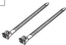

AC cord, Fixing bands × 2

Remote Control Batteries
Requires two AA batteries.
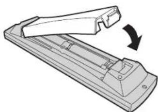
- Pull and hold the hook, then open the battery cover.
- Insert batteries - note correct polarity (+ and -).
- Replace the cover.


Helpful Hint:
For frequent remote control users, replace old batteries with Alkaline batteries for longer life.

Precaution on battery use
Incorrect installation can cause battery leakage and corrosion that will damage the remote control transmitter. Disposal of batteries should be in an environment-friendly manner.
Observe the following precautions:
- Batteries should always be replaced as a pair. Always use new batteries when replacing the old set.
- Do not combine a used battery with a new one.
- Do not mix battery types (example: "Zinc Carbon" with "Alkaline").
- Do not attempt to charge, short-circuit, disassemble, heat or burn used batteries.
- Battery replacement is necessary when the remote control acts sporadically or stops operating the Plasma Display.
Connections
When connecting the speakers, be sure to use only the optional accessory speakers.
Refer to the speaker's Installation Manual for details on speaker installation.
![graph TD A["Speakers (Optional accessories)"] --> B["AC cord fixing"] B --> C["Speaker Terminals (R)"] B --> D["SPEAKERS Terminals (L)"] C --> E["① Connect the AC cord plug to Plasma Display."] C --> F["② Fix the left side clamper."] C --> G["③ Fix the right side clamper."] D --> H["④ Close Push unt…](/content/2026/05/998345/images/ea44eac0b2a0ebf84c4c82e9ac79ad621793582b3f1d61f478f1c96de1e7cf49.jpg)
Note: At factory shipment, Terminal boards are installed in SLOT 2 and SLOT 3.
Connections
PC Input Terminals connection
![graph TD A["COMPUTER"] --> B["Conversion adapter (if necessary)"] B --> C["PC cable"] C --> D["Mini D-sub 15p"] D --> E["PC IN"] D --> F["Audio"] D --> G["Stereo plug"]](/content/2026/05/998345/images/9c09a3e78f5bbaf8d636faf5c50df28142043c9c51bc9663b3216de2813e13fb.jpg)
Connect a cable which matches the audio output terminal on the computer.
Notes:
- Due to space limitations, occasionally you may have trouble connecting Mini D-sub 15P cable with ferrite core to PC input Terminal.
- Computer signals which can be input are those with a horizontal scanning frequency of 15 to 110 kHz and vertical scanning frequency of 48 to 120 Hz. (However, the image will not be displayed properly if the signals exceed 1,200 lines.)
- The display resolution is a maximum of 1,440 × 1,080 dots when the aspect mode is set to "NORMAL", and 1,920 × 1,080 dots when the aspect mode is set to "FULL". If the display resolution exceeds these maximums, it may not be possible to show fine detail with sufficient clarity.
- The PC input terminals are DDC1/2B-compatible. If the computer being connected is not DDC1/2B-compatible, you will need to make setting changes to the computer at the time of connection.
- Some PC models cannot be connected to the set.
- There is no need to use an adapter for computers with DOS/V compatible Mini D-sub 15P terminal.
- The computer shown in the illustration is for example purposes only. • Additional equipment and cables shown are not supplied with this set.
- Do not set the horizontal and vertical scanning frequencies for PC signals which are above or below the specified frequency range.
- Component Input is possible with the pin 1, 2, 3 of the D-sub 15P Connector.
- Change the "COMPONENT/RGB-IN SELECT" setting in the "SET UP" menu to "COMPONENT" (when COMPONENT/RGB connection) or "RGB" (when RGB signal connection). (see page 37)
Signal Names for Mini D-sub 15P Connector
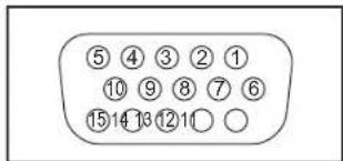
Pin Layout for PC Input Terminal
| Pin No. | Signal Name | Pin No. | Signal Name | Pin No. | Signal Name |
| 1 | R (PR/CR) | 6 | GND (Ground) | 11 | NC (not connected) |
| 2 | G (Y) | 7 | GND (Ground) | 12 | SDA |
| 3 | B ( PB/CB ) | 8 | GND (Ground) | 13 | HD/SYNC |
| 4 | NC (not connected) | 9 | NC (not connected) | 14 | VD |
| 5 | GND (Ground) | 10 | GND (Ground) | 15 | SCL |
SERIAL Terminals connection
The SERIAL terminal is used when the Plasma Display is controlled by a computer.


Pin layout for SERIAL Terminal
Notes:
- Use the RS-232C cable to connect the computer to the Plasma Display.
- The computer shown is for example purposes only. Additional equipment and cables shown are not supplied with this set.
The SERIAL terminal conforms to the RS-232C interface specification, so that the Plasma Display can be controlled by a computer which is connected to this terminal.
The computer will require software which allows the sending and receiving of control data which satisfies the conditions given below. Use a computer application such as programming language software. Refer to the documentation for the computer application for details.
Communication parameters
| Signal level | RS-232C compliant |
| Synchronization method | Asynchronous |
| Baud rate | 9600 bps |
| Parity | None |
| Character length | 8 bits |
| Stop bit | 1 bit |
| Flow control | - |
| RS-232C Conversion cable | |
| D-sub 9-pin female Details | |
| R X D 2 | |
| T X D 3 | |
| 5 | GND |
| • Non use4 6 | |
| 78 | Shorted |
| 1 • 9 | NC |
Basic format for control data
The transmission of control data from the computer starts with a STX signal, followed by the command, the parameters, and lastly an ETX signal in that order. If there are no parameters, then the parameter signal does not need to be sent.
![graph TD A["STX"] --> B["Start (02h)"] C["C1"] --> D["3-character command (3 bytes)"] E["C2"] --> D F["C3"] --> G[":"] H["P1"] --> I["Colon"] J["P2"] --> K["Parameter(s) (1 - 5 bytes)"] L["P3"] --> K M["P4"] --> K N["P5"] --> O["ETX"] P["End (03h)"] --> O](/content/2026/05/998345/images/454f2e1c3a3c75fc4f8576d24a073b00cc3174cd6e8d28118e2af5edd1dd08b3.jpg)
Notes:
- If multiple commands are transmitted, be sure to wait for the response for the first command to come from this unit before sending the next command.
- If an incorrect command is sent by mistake, this unit will send an "ER401" command back to the computer.
Command
| Command | Parameter | Control details |
| PON | None | Power ON |
| POF | None | Power OFF |
| AVL | ** | Volume 00 - 63 |
| AMT | 0 | Audio MUTE OFF |
| 1 | Audio MUTE ON | |
| IMS | None | Input select (toggle) |
| SL1 | Slot1 input | |
| SL2 | Slot2 input | |
| SL3 | Slot3 input | |
| PC1 | PC input | |
| DAM | None | Screen mode select (toggle) |
| NORM | NORMAL (4 : 3) | |
| ZOOM | ZOOM | |
| FULL | FULL | |
| JUST | JUST | |
| SELF | Panasonic AUTO |
With the power off, this display responds to PON command only.
Connections
DVI-D connection
![graph TD A["PC with DVI-D video out"] --> B["DVI-D video cable (Within 5 m)"] B --> C["Mini-plug (M3)"] C --> D["Audio Interface"] D --> E["SLOT2"] E --> F["Computer with monitor"]](/content/2026/05/998345/images/d2aaf6239aae452fa960d5e58dc57323b9175aab3d0abe1faf0e2590b78b117a.jpg)
DVI-D Input Connector Pin Layouts

Connection port view
| Pin No. | Signal Name | Pin No. | Signal Name |
| 1 | T.M.D.S. data 2- | 13 | T.M.D.S. data 3+ |
| 2 | T.M.D.S. data 2+ | 14 | +5 V DC |
| 3 | T.M.D.S. data 2/4 shielded | 15 | Ground |
| 4 | T.M.D.S. data 4- | 16 | Hot plug sense |
| 5 | T.M.D.S. data 4+ | 17 | T.M.D.S. data 0- |
| 6 | DDC clock | 18 | T.M.D.S. data 0+ |
| 7 | DDC data | 19 | T.M.D.S. data 0/5 shielded |
| 8 | —— | 20 | T.M.D.S. data 5- |
| 9 | T.M.D.S. data 1- | 21 | T.M.D.S. data 5+ |
| 10 | T.M.D.S. data 1+ | 22 | T.M.D.S. clock shield |
| 11 | T.M.D.S. data 1/3 shielded | 23 | T.M.D.S. clock+ |
| 12 | T.M.D.S. data 3- | 24 | T.M.D.S. clock- |
Notes:
• Additional equipment, cables and adapter plugs shown are not supplied with this set. • Refer to page 45 for applicable input signal.
COMPONENT / RGB connection & RGB signal (R, G, B)
![graph TD A["Example of input signal source"] --> B["DVD"] B --> C["Digital TV-SET-TOP-BOX (DTV-STB)"] C --> D["Component Video OUT"] D --> E["RCA-BNC adapter plug"] D --> F["Computer"] D --> G["RGB Camcorder or"]](/content/2026/05/998345/images/4ce14282a2b92479f8a45bdf18f9e64e222c376ad178527d9151666463654462.jpg)
Notes:
- Change the "COMPONENT/RGB-IN SELECT" setting in the "SET UP" menu to "COMPONENT" (when COMPONENT/RGB connection) or "RGB" (when RGB signal connection). (see page 37) • Additional equipment, cables and adapter plugs shown are not supplied with this set. • SYNC ON G signal is needed. (see page 39)
Power ON / OFF
Connecting the AC cord plug to the Plasma Display.
Fix the AC cord plug securely to the Plasma Display with the clamper. (see page 9)

Connecting the plug to the Wall Outlet
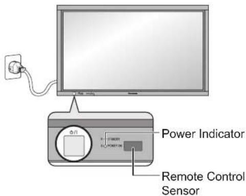
Press the Power switch on the Plasma Display to turn the set on: Power-On.
Power Indicator: Green
Example: The screen below is displayed for a while after the Plasma Display is turned on. (Setting condition is an example.)
When the POWER is turned on for the first time, the LANGUAGE selection screen is displayed.
From the second time on, language selection can be done from the setup menu. (See page 18)
Select the desired language using the ▲ or ▼ button and press the ACTION (■) button.

From the second time on, the screen shown below is displayed for a while (setting condition is an example).


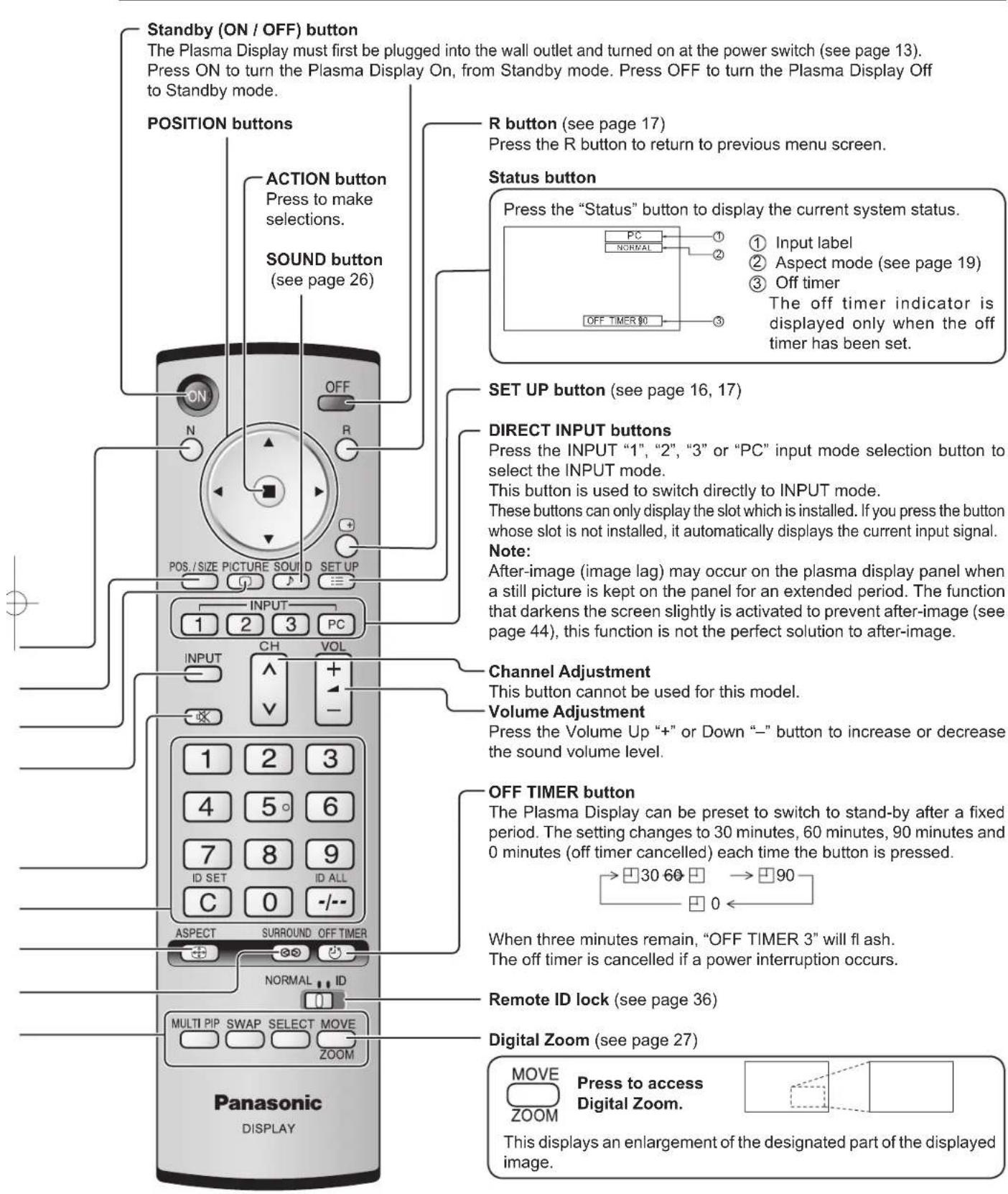
Press the button on the remote control to turn the Plasma Display off.
Power Indicator: Red (standby)
Press the Ⓞ button on the remote control to turn the Plasma Display on.
Power Indicator: Green
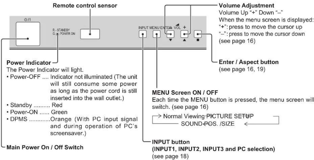
Turn the power to the Plasma Display off by pressing the ⏻/I switch on the unit, when the Plasma Display is on or in standby mode.
Note:
During operation of the power management function, the power indicator turns orange in the power off state.

Basic Controls
SURROUND button
The surround setting switches on and off each time the SURROUND button is pressed.
The benefits of surround sound are enormous. You can be completely enveloped in sound; just as if you were at a concert hall or cinema.
Note:
The surround settings are memorized separately for each AUDIO MENU (STANDARD, DYNAMIC, CLEAR).

N button (see page 20, 24, 25, 26)
POS. /SIZE button (see page 20)
PICTURE button (see page 24)
INPUT button
(INPUT1, INPUT2, INPUT3 and PC selection)
Press to select INPUT1, INPUT2, INPUT3 and PC input SLOTS sequentially. (see page 18)
Sound mute On / Off (see page 26)
Numeric buttons (see page 36, 42)
ASPECT button
Press to adjust the aspect. (see page 19)
MULTI Window buttons (see page 22)
Basic Controls
On-Screen Menu Displays
To PICTURE adjust menu (see page 24)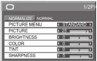
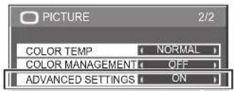


Press to select "ON".
Press to enter ADVANCED SETTINGS.
To ADVANCED SETTINGS (see page 24, 25)
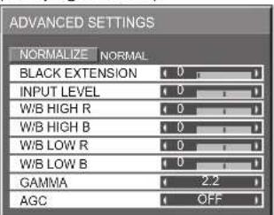
To POS./SIZE adjust menu (see page 20) During "VIDEO (S VIDEO)", "Digital", "SDI" and "HDMI" input signal.
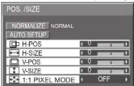
During "COMPONENT", "RGB" and "PC" input signal.

The MENU button on the unit can also be pressed.

Each time the MENU button is pressed, the menu screen will switch.
→ Normal Viewing PICTURE SETUP SOUND←POS./SIZE

To SOUND adjust menu (see page 26)


① Press to select.
[from the unit]

① Press to select. ② Press to access each adjust screen.


Note:
Menu that cannot be adjusted is grayed out. Adjustable menu changes depending on signal, input and menu setting.
Press to access each adjust screen. Press to return to next menu screen. Press the R button to return to previous menu.
To SIGNAL screen for VIDEO (S VIDEO) (see page 37, 38)
To SIGNAL screen for COMPONENT (see page 38)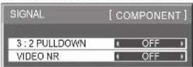
To SIGNAL screen for RGB (see page 38, 39)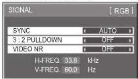
To SIGNAL screen for Digital (see page 38, 39) Note: "SIGNAL" setup menu displays a different setting condition for each input signal. (see page 18)
To setup SCREENSAVER
(See page 30-32)
Press to select START TIME/ FINISH TIME (When TIME OF DAY is selected). Press to select SHOW DURATION/ SAVER DURATION (When INTERVAL is selected). Press to set up.
Press the R button to return to "SET UP" menu.


To setup MULTIDISPLAY screen.
(See page 34)
Press to select
POWER ON TIME /
POWER OFF TIME.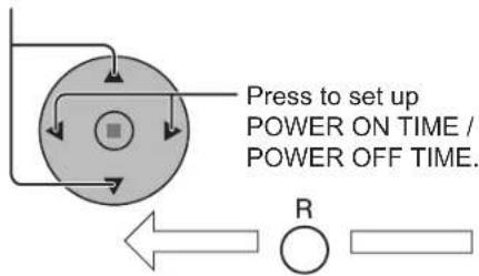
Press the R button to return to "SET UP" menu.

To SET UP TIMER selection screen. (see page 28, 29)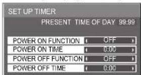
Selecting the input signal
Select the input signals to be connected by installing the optional Terminal Boards.

Press to select the input signal to be played back from the equipment which has been connected to the Plasma Display.
Input signals will change as follows:


Notes:
- Selecting is also possible by pressing the INPUT button on the unit.
- Input terminal will not be selected if the terminal board is not installed into the SLOT.
- Select to match the signals from the source connected to the component/RGB input terminals. (see page 37)
- In 2 screen display, the same input mode cannot be selected for the main picture and sub picture.

Selecting the On-Screen Menu Language

ASPECT Controls
The Plasma Display will allow you to enjoy viewing the picture at its maximum size, including wide screen cinema format picture.
ASPECT

Press repeatedly to move through the aspect options:

[from the unit]

The aspect mode changes each time the ENTER button is pressed.
[During MULTI PIP Operations]
• Picture and Picture, Picture in Picture:

- Others: Aspect switching is not possible.
Notes:
- For PC signal input, the mode switches between "NORMAL", "ZOOM" and "FULL" only.
- For a 1125 (1080) / 60i · 50i · 60p · 50p · 24p · 25p · 30p · 24sF, 1250 (1080) / 50i, 750 (720) / 60p · 50p signal input, the mode is set to "FULL" mode, and switching is not possible.
- Panasonic AUTO can be selected only during Video signal input.
- The aspect mode is memorized separately for each input terminal.
| Mode Picture Explanation | ||||
| NORMAL |  | NORMAL will display a 4:3 picture at its standard 4:3 size. | ||
| ZOOM |  | → | 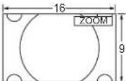 | ZOOM mode magnifi es the central section of the picture. |
| FULL |  | → |  | FULL will display the picture at its maximum size but with slight elongation. |
| JUST |  | → |  | JUST mode will display a 4:3 picture at its maximum size but with aspect correction applied to the center of the screen so that elongation is only apparent at the left and right edges of the screen. The size of the picture will depend on the original signal. |
| Panasonic AUTO |  | → |  | The display will automatically become enlarged (depending on the picture source), allowing you to view the picture at its maximum size.Notes:Panasonic AUTO mode is designed to automatically adjust the aspect ratio to handle a mix of 16:9 and 4:3 program material. Certain 4:3 program material, such as stock market data screens, may occasionally cause the image size to change unexpectedly. When viewing such programs, it is recommended that the ASPECT be set to NORMAL.If adjusting the PICTURE V-POS/V-SIZE in Panasonic AUTO with FULL mode, the adjustment is not memorized. When exiting the mode, the screen will return to a former adjustment.Panasonic AUTO can not be selected while TY-FB9BD (optional BNC Dual Video Terminal Board) is installed. |
| For an elongated image | Image is expanded | |||
 | → |  | ||
| For a 4:3 image | p | |||
Note: Do not allow the picture to be displayed in NORMAL mode for an extended period, as this can cause a permanent after-image to remain on the Plasma Display Panel.

Adjusting POS. /SIZE
1
2
Press to display the POS. /SIZE menu.
Press to select AUTO SETUP / H-POS / H-SIZE / V-POS / V-SIZE / DOT CLOCK / CLOCK PHASE / 1:1 PIXEL MODE.
3

Press to adjust POS. /SIZE.
Press to exit from adjust mode.
Notes:
- Adjustment details are memorized separately for different input signal formats (Adjustments for component signals are memorized for 525 (480) / 60i · 60p, 625 (575) / 50i · 50p, 1125 (1080) / 60i · 50i · 60p · 50p · 24p · 25p · 30p · 24sF, 1250 (1080) / 50i, 750 (720) / 60p · 50p each, and RGB/PC/Digital signals are memorized for each frequency.)
- If a "Cue" or "Rew" signal from a VCR or DVD player is received, the picture position will shift up or down. This picture position movement cannot be controlled by the POS. /SIZE function.
- If adjusting the PICTURE V-POS / V-SIZE in Panasonic AUTO with FULL mode, the adjustment is not memorized. When exiting the mode, the screen will return to a former adjustment.

During "VIDEO (S VIDEO)", "Digital", "SDI" and "HDMI" input signal.
During "COMPONENT", "RGB" and "PC" input signal.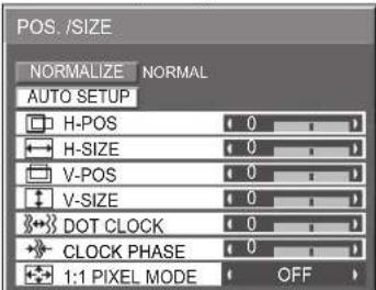
Helpful Hint ( Ⓞ NORMALIZE Normalization)
While the POS. /SIZE display is active, if either the N button on the remote control is pressed at any time or the ACTION (■) button is pressed during "NORMALIZE", then all adjustment values are returned to the factory settings.
AUTO SETUP
Automatically adjust H-POS / V-POS / CLOCK PHASE / DOT CLOCK and set H-SIZE / V-SIZE the standard value when RGB signal is input.
Notes:
- If the dot clock frequency is 162 MHz or higher, DOT CLOCK cannot be made.
- If the image is that the edge is hardly figured out or shadowy, that cannot be adjusted automatically. In such case, press AUTO SETUP again after changing the image to the clearer one.
- When DVI-D is input, CLOCK PHASE cannot be adjusted automatically.
- Select NORMALIZE in POS./SIZE and press the ACTION (■) button when appropriate adjustment cannot be made.
H-POS: Adjust the horizontal position.

H-SIZE: Adjust the horizontal size.
V-POS: Adjust the vertical position.
V-SIZE: Adjust the vertical size.
DOT CLOCK (During "COMPONENT", "RGB" and "PC" input signal)
Periodic striped pattern interference (noise) may occur when a striped pattern is displayed. If this happens, adjust so that any such noise is minimized.
CLOCK PHASE (During "COMPONENT", "RGB" and "PC" input signal)
Eliminate the flickering and distortion.
1:1 PIXEL MODE: Adjusts the display size when 1125i, 1125p or 1250i signal is input.

Notes:
- Select ON when you would like to replay 1920 x 1080 input signal. • Applicable input signal; 1125 / 50i · 60i · 24sF · 24p · 25p · 30p · 50p · 60p · 1250i
- Select OFF when flickering is shown around the image. • H-SIZE, V-SIZE and DOT CLOCK cannot be adjusted when ON is selected.
Helpful Hint (NORMALIZE Normalization)
While the POS./SIZE display is active, if either the N button on the remote control is pressed at any time or the ACTION (■) button is pressed during "NORMALIZE", then all adjustment values are returned to the factory settings.
MULTI PIP
MULTI PIP
Press repeatedly.
Each time pressing this button main picture and sub picture will be displayed as follows below.

[Picture and Picture] [Picture] [Picture] [Picture]![graph TD A["Normal Viewing"] --> B["Main picture Sub picture"] B --> C["Main picture"] C --> D["Sub picture"] D --> E["Main picture Sub picture"] E --> F["Main picture"] F --> G["SWAP"] G --> H["Swap Swap"] H --> I["B A"] I --> J["SWAP"] J --> K["B A"] K --> L["SWAP"] L --> M["B A"] M --> N["SWAP"]…](/content/2026/05/998345/images/eb4813e8eb307f785ce30ca87555ea1d5a03c2dfdd7b081cc12ead43ecf1adb6.jpg)

Press to select the input mode.
Under main Picture and sub picture display, select the picture which you would like to change input modes.
Notes:
- The sub picture sound is heard while a sub picture operation is underway.
- The sub picture operation automatically returns to the main picture operation if a sub picture operation has not been performed for about 5 seconds or if any of the remote control buttons is pressed (except INPUT button).
Press to change input signal.
[Example] Main picture label is bright Sub picture label is bright![graph TD A["Input Mode A"] -->|PC1 VDDR02| B["Select"] B -->|B| A A -->|PC1 VDDR02| C["Output Module A"] style A fill:#f9f,stroke:#333 style B fill:#ccf,stroke:#333 style C fill:#cfc,stroke:#333 note right of A: Input modes switching is possible](/content/2026/05/998345/images/4aec32616c52575f1888bf31a72ea3558e0e7250fa3681a2bf2b53c3a5ac5898.jpg)
Main picture label is changed Sub picture label is changed![graph TD A["Block A"] -->|V3.04 V5.01| B["Block B"] A -->|V6.02| D["Block D"] B -->|Picture is changed| A D -->|Picture is changed| A](/content/2026/05/998345/images/f5ec2ba8eb1612c92cdc9d567346b8a927a5380535fef20494d7d7e19ec0fa47.jpg)
INPUT

Press to change input signal.

Press to move the sub picture.
Each time the location of the sub picture will be moved.
Notes:
- This button is effective only in the picture in picture.
- The sub picture may be hidden by the on screen display, depending on its position.

Notes:
- Sound output is from the picture which is selected in Audio OUT(PIP) (See page 26). • In 2 screen display, the same input mode cannot be selected for the main picture and sub picture.
- The main picture and sub picture are processed by different circuits, resulting in a slight difference in the clarity of the pictures. There may also be a difference in the picture quality of the sub picture depending on the type of signals displayed on the main picture and depending on the 2-picture display mode.
- Due to the small dimensions of the sub pictures, these sub pictures cannot be shown in detail.
- Computer screen picture is displayed in a simplified format, and it may not be possible to discern details on them satisfactorily.
- Following combinations of two analog signals cannot be displayed simultaneously;
Component - Component, Component - PC (RGB), PC (RGB) - Component, PC (RGB) - PC (RGB)
- Following signals are not applicable to this menu.
1125 / 50p · 60p, 1152 × 864 @60 Hz, 1400 × 1050 @60 Hz, 1600 × 1200 @60Hz, 1920 × 1200 @60 Hz
Advanced PIP
1
SET UP
Press to display the Setup menu.
2

Press to select "OSD Language".
3
SURROUND
◀▶
Press and hold until the Options menu is displayed.
4

Press to select Advanced PIP.
5

Press to adjust the menu.
Off: Sets normal two-screen display mode (see page 22).
On: Sets Advanced PIP mode.
Press to confirm.
6

Press to exit from
Options menu.
(When Advanced PIP is On)
7

Press repeatedly.
Each time pressing this
![graph TD A["One screen"] --> B["Advanced PIP"] B --> C["Main screen Sub screen"] C --> D["Final Screen"]](/content/2026/05/998345/images/c5869ebb4c6e7926cb9930a74be859ac9923c9f5b0cbbe72d2edf2f84459cfd5.jpg)
button, the main picture and sub picture will be displayed as above.
Note:


INPUT MOVE buttons for
2
Notes:


- Adva
nced PIP corresponding signal
| Sub screen Main screen | |
| NTSC, PAL, SECAM (tuner, video)525i, 525p, 625i, 625p, 750/60p, 750/50p, 1125/60i, 1125/50i, 1250/50i (Component Video, RGB, DVI, SDI, HDMI) | 640x480@60Hz, 852x480@60Hz, 1024x768@60Hz, 1366x768@60Hz (RGB, DVI, HDMI)1280x768@60Hz (DVI) |
• Sound output is from the picture which is selected in Audio OUT (PIP) (See page 26).
• In 2 screen display, the same input mode cannot be selected for the main picture and sub picture.
- The main picture and sub picture are processed by different circuits, resulting in a slight difference in the clarity of the pictures. There may also be a difference in the picture quality of the sub picture depending on the type of signals displayed on the main picture and depending on the 2-picture display mode.
- Due to the small dimensions of the sub pictures, these sub pictures cannot be shown in detail.
- Computer screen picture is displayed in a simplified format, and it may not be possible to discern details on them satisfactorily.
- Following combinations of two analog signals cannot be displayed simultaneously;
Component - Component, Component - PC (RGB), PC (RGB) - Component, PC (RGB) - PC (RGB)
- Following signals are not applicable to this menu.
1125 / 50p • 60p, 1152 × 864 @60 Hz, 1400 × 1050 @60 Hz, 1600 × 1200 @60Hz, 1920 × 1200 @60 Hz
• Refer to each board's operating instruction for DVI, SDI, HDMI's corresponding signals.
PICTURE Adjustments
1
PICTURE

Press to display the PICTURE menu.
2
Select to adjust each item.
![graph TD A["Top Left Arrow"] --> B["Center Square"] C["Bottom Right Arrow"] --> B D["Bottom Left Arrow"] --> B E["Bottom Right Arrow"] --> B B --> F["Right Arrow"]](/content/2026/05/998345/images/7025f0b39cf19b46bf0b0e1830fc9cdcb77d4eaab2d4e2837ba472d0fa0e9571.jpg)
Press to select the menu to adjust.
Select the desired level by looking at the picture behind the menu.
Note:
Menu that cannot be adjusted is grayout. Adjustable menu changes depending on signal, input and menu setting.


Press the left ◀ or right▶ button to switch between modes.

STANDARD
For viewing in standard (evening lighting) environments. This menu selects the normal levels of BRIGHTNESS and PICTURE.

DYNAMIC
For viewing in brighter environments. This menu selects higher than normal levels of BRIGHTNESS and PICTURE.

Press to select "ON".
Press to enter Advanced Settings.
ADVANCED SETTINGS ON
Enables fine picture adjustment at a professional level (see next page).

ADVANCED SETTINGS OFF
Displays images with settings of the PICTURE menu.
CINEMA
Ideal for movies.
SUPER CINEMA
Displays velvety picture.
Note:
If you would like to change the picture and color of the selected PICTURE menu to something else, adjust using the items in the PICTURE menu. (see next page)
Press the left ◀ or right ▶ button to switch between modes.

COLOR MANAGEMENT ON
Enables vivid color adjustment automatically.
Helpful Hint

NORMALIZE
Normalization)
While the "PICTURE" menu is displayed, if either the N button on the remote control is pressed at any time or the ACTION
(■) button is pressed during "NORMALIZE", then all adjustment values are returned to the factory settings.
PICTURE Adjustments
| Item | Effect | Adjustments |
| PICTURE |  | Adjusts the proper picture contrast. |
| BRIGHTNESS |  | Adjusts for easier viewing of dark pictures such as night scenes and black hair. |
| COLOR |  | Adjusts color saturation. |
| TINT | [R  | Adjusts for natural flesh tones. |
| SHARPNESS |  | Adjusts picture sharpness. |
Notes:
- "COLOR" and "TINT" settings cannot be adjusted for "RGB/PC" and "Digital" input signal.
- You can change the level of each function (PICTURE, BRIGHTNESS, COLOR, TINT, SHARPNESS) for each PICTURE MENU.
- The "TINT" setting can be adjusted for NTSC signal only during "VIDEO (S VIDEO)" input signal.
- In PICTURE, there is not a noticeable change even when contrast is increased with a bright picture or reduced with a dark picture.
ADVANCED SETTINGS
| Item | Effect | Details | |
| BLACK EXTENSION |  | Adjusts the dark shades of the image in gradation. | |
| INPUT LEVEL |  | Adjustment of parts which are extremely bright and hard to see.(This cannot be adjusted when the input signal is Digital.) | |
| W/B HIGH R |  | Adjusts the white balance for light red areas. | |
| W/B HIGH B |  | Adjusts the white balance for light blue areas. | |
| W/B LOW R |  | Adjusts the white balance for dark red areas. | |
| W/B LOW B |  | Adjusts the white balance for dark blue areas. | |
| GAMMA |  | S CURVE 2.0 2.2 2.5 | |
| AGC |  | Increases the brightness of dark signal automatically. | |
Notes:
- Carry out "W/B" adjustment as follows.
- Adjust the white balance of the bright sections using the "W/B HIGH R" and "W/B HIGH B" settings.
- Adjust the white balance of the dark sections using the "W/B LOW R" and "W/B LOW B" settings.
- Repeat steps 1 and 2 to adjust.
Steps 1 and 2 affect each other's settings, so repeat each step in turn to make the adjustment.
- The adjustment values are memorized separately for each input terminal.
- The adjustment range values should be used as an adjustment reference.
- The adjustment values are memorized separately for each input terminal. - The adjustment range values should be used as an adjustment reference.
| Helpful Hint (N NORMALIZE Normalization) |
| On the remote control unit, while the “ADVANCED SETTINGS” menu is displayed, if either the N button is pressed at any time or the ACTION (■) button is pressed during “NORMALIZE”, then all adjustment values are returned to the factory settings. |
SOUND Adjustment
1
SOUND
♪
Press to display the SOUND menu.
2
Select to adjust each item.
![graph TD A["Top"] --> B["Center"] B --> C["Bottom"] C --> D["Right"] D --> E["Left"] E --> F["Right"] F --> G["Bottom"] G --> H["Left"] H --> I["Right"] I --> J["Bottom"]](/content/2026/05/998345/images/972f18c8173a7806ef882ac466c0108166f8eabd60923ed9b0864c295827889f.jpg)
Press to select the menu to adjust.
Select the desired level by listening to the sound.


Notes:
- Press the SURROUND button to directly turn the surround effect ON and OFF. (see page 14) • BASS, MID, TREBLE and SURROUND settings are memorized separately for each AUDIO MENU.
Helpful Hint

NORMALIZE
Normalization)
While the "SOUND" menu is displayed, if either the N button on the remote control is pressed at any time or the ACTION (■) button is pressed during "NORMALIZE", then all adjustment values are returned to the factory settings.
MUTE
Useful when answering the phone or receiving unexpected visitors.
Press this button to mute the sound.
Press again to reactivate sound. Sound is also reactivated when power is turned off or volume level is changed.
26
Digital Zoom
This displays an enlargement of the designated part of the displayed image.
1 Display the "Operation Guide".
Press to access Digital Zoom. The "Operation Guide" will be displayed.

During Digital Zoom, only the following buttons can be operated.
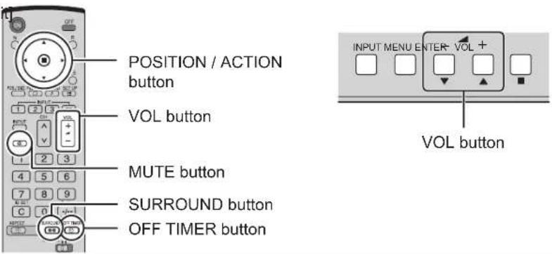
[Remote control] [Uni
2 Select the area of the image to be enlarged.

Press on the enlargement location to select.
The cursor will move.

3 Select the magnification required for the enlarged display.
Each time this is pressed, the magnification factor changes. This is shown in the image being displayed.
![graph LR A["×1×2"] --> B["×3×4"] B --> C[" "] C --> D[" "]](/content/2026/05/998345/images/94819c973cc27753f2fe938bfa4daacf65c728dc67dd2ffec2d93123a2a45c2c.jpg)
4 Return to normal display (quit Digital Zoom).

Press to exit from the Digital Zoom.
Notes:
- When power goes OFF (including "Off Timer" operation), Digital Zoom terminates.
- The Digital Zoom function cannot be selected while in the following operation state: "Multi-viewer" (Picture in Picture, Picture out Picture, Picture and Picture) operation. (see page 22)
- While Digital Zoom is in operation, "Adjusting POS. /SIZE" cannot be used.
- Following signals are not applicable to this menu. 1125 / 50p • 60p, 1152 × 864 @60 Hz, 1400 × 1050 @60 Hz, 1600 × 1200 @60Hz, 1920 × 1200 @60 Hz
PRESENT TIME SETUP / SET UP TIMER
The timer can switch the Plasma Display ON or OFF.
Before attempting Timer Set, confirm the PRESENT TIME OF DAY and adjust if necessary. Then set POWER ON TIME / POWER OFF TIME.
1

Press to display the SET UP menu.

2

Press to select SET UP TIMER or PRESENT TIME SETUP.
Press to display the SET UP TIMER screen or PRESENT TIME SETUP screen.

PRESENT TIME SETUP
Display the PRESENT TIME SETUP screen.
To set up PRESENT TIME OF DAY, follow the procedure described below.
1
![graph TD A["Top"] --> B["Center"] B --> C["Right"] B --> D["Left"] B --> E["Bottom"] B --> F["Square Node"] style B fill:#ccc,stroke:#333](/content/2026/05/998345/images/c38779be9a93a4f5f62120d0a26c89e7ee98f7a0874bbb05479c810d73e473f4.jpg)
Press to select PRESENT TIME OF DAY.
Press to set up PRESENT TIME OF DAY.
▶ button: Forward
button: Back
Notes:
- Pressing "◀" or "▶" button once changes PRESENT TIME OF DAY by 1 minute.
- Pressing "◀" or "▶" button continuously changes PRESENT TIME OF DAY by 15 minutes.

2

Press to select Set.
Press to store PRESENT TIME SETUP.
Note:
Set cannot be selected unless PRESENT TIME OF DAY is set.

3
Press to exit from PRESENT TIME SETUP.
28
SET UP TIMER
Display the SET UP TIMER SCREEN.
1
![graph TD A["Top"] --> B["Center"] B --> C["Bottom"] C --> D["Right"] D --> E["Left"] E --> F["Right"] F --> G["Bottom"] G --> H["Left"] H --> I["Right"] I --> J["Bottom"]](/content/2026/05/998345/images/93aff822abbe46a4b0a54e665e7124d46898a15341af077aa612e0501c38ea33.jpg)
Press to select POWER ON TIME / POWER OFF TIME.
Press to set up POWER ON TIME / POWER OFF TIME.
▶ button: Forward button: Back

- Pressing “◀” or “▶” button once changes POWER ON TIME / POWER OFF TIME 1 minute.
- Pressing “◀” or “▶” button continuously changes POWER ON TIME / POWER OFF TIME by 15 minutes.
2
![graph TD A["Top"] --> B["Center"] B --> C["Bottom"] C --> D["Right"] D --> E["Left"] E --> F["Right"] F --> G["Bottom"] G --> H["Right"] H --> I["Left"] I --> J["Right"] J --> K["Bottom"]](/content/2026/05/998345/images/ff12cb535ce3d6c2def05bcb2934aef181c63f91f9e81400c39ab91cc8a91fce.jpg)
Press to select POWER ON FUNCTION / POWER OFF FUNCTION.
Press to select ON.
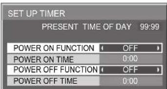
Press twice to exit from SET UP.
Note:
Timer function will not work unless "PRESENT TIME OF DAY" is set.
SCREENSAVER (For preventing after-images)
Do not display a still picture, especially in NORMAL mode, for any length of time. If the display must remain on, a SCREENSAVER should be used.
1
2

Press to display the SET UP menu.
Press to select the SCREENSAVER.
Press to select the SCREENSAVER screen.

3
NEGATIVE / SCROLL selection
![graph TD A["Top Left Arrow"] --> B["Center Square"] C["Right Arrow"] --> B D["Bottom Right Arrow"] --> B B --> E["Bottom Left Arrow"]](/content/2026/05/998345/images/b4eb6329820a3d46faefb2f3bd536b0e55651d3c005b758ef6886ec2203e604d.jpg)
Press to select the FUNCTION.
Press to select the desired function.
WHITE BAR SCROLL <NEGATIVE
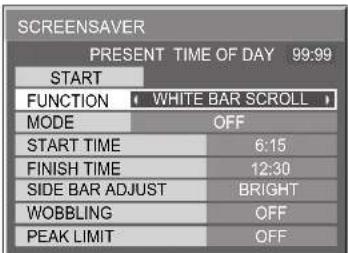
WHITE BAR SCROLL : A white bar will scroll from left to right. NEGATIVE : A negative image will be displayed on the screen.
4
MODE selection
![graph TD A["Top"] --> B["Center"] B --> C["Right"] B --> D["Left"] B --> E["Bottom"] B --> F["Right"] style B fill:#ccc,stroke:#333,stroke-width:2px](/content/2026/05/998345/images/398c71d5c748db15770ae5c303e6c0dcbcacb901485b07c6f84f175907b53441.jpg)
Press to select the MODE.
Press to select each mode items.
![graph TD A["OFF"] --> B["INTERVAL : Operates when SHOW DURATION and SAVER DURATION are set up and those times arrive."] B --> C["TIME OF DAY : Operates when START TIME and FINISH TIME are set up and those times arrive."] C --> D["ON : Operates when START is selected and the ACTION ( ) button is pres…](/content/2026/05/998345/images/fee2e6a4fb8ee5be633191a2ad13c5e36e083acd40aaf9fe859c1f99bda5429a.jpg)

5
START setting

When the MODE is set to ON, press to select START.
Press to start SCREENSAVER.
The menu screen will disappear and the SCREENSAVER will be activated. To stop the SCREENSAVER under ON, press the R button.

Setup of SCREENSAVER Time
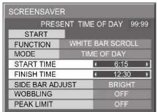
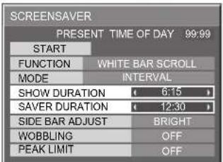
After selecting TIME OF DAY or INTERVAL, the relevant Time Setup will become available for selection and the Operating Time may be set. (Time cannot be set when "MODE" is "ON" or "OFF".)


Press to select START TIME / FINISH TIME (When TIME OF DAY is selected). Press to select SHOW DURATION / SAVER DURATION (When INTERVAL is selected).
Press to setup. ▶ button: Forward button: Back
Notes:
- Pressing "◀ or "▶ button once changes the Time 1 minute. [However, switching occurs every 15 minutes when Periodic Time is selected.]
- Pressing “◀ or “▶ button continuously changes the Time by 15 minutes.


Note: Timer function will not work unless "PRESENT TIME OF DAY" is set.
Reduces screen after-image
These functions prevent the occurrence of an "after image" on the display when turned ON.
WOBBLING: Automatically shifts the display image at a dot level pitch (therefore unnoticeable to the eye) to prevent after image of sharper contour of image.
ON1: Shifts the image over time.
ON2: Shifts the image depending on screen-detection.
PEAK LIMIT: Suppresses image contrast (peak brightness).
Note: When a still picture is viewed for an extended time, the screen may become slightly darker. (see page 44)
1
2

Press to display the SET UP menu. Press to select "SCREENSAVER".
3
![graph TD A["Top Left Arrow"] --> B["Center Square"] C["Right Arrow"] --> B D["Bottom Right Arrow"] --> B B --> E["Bottom Left Arrow"]](/content/2026/05/998345/images/77b2202c13616a355ae6a05743bf152729febc922cf247745a995544d386d17f.jpg)
Press to display SCREENSAVER menu.
Press to select "WOBBLING" or "PEAK LIMIT".
Press to select "ON1", "ON2" or "OFF" (WOBBLING). "ON" or "OFF" (PEAK LIMIT).


SCREENSAVER (For preventing after-images)
SIDE BAR ADJUST
Do not display a picture in NORMAL mode for an extended period, as this can cause an after-image to remain on the side bars on either side of the display field.
To reduce the risk of such an after-image, change the brightness of the side bars.

This function may be applicable to the non-picture area.

Display the SCREENSAVER screen.
(Refer to the previous page, operation guide steps 1 and 2)
1

2
Notes:
• To reduce the occurrence of after-images, set the SIDE BAR ADJUST to BRIGHT. - The side bar may flash (alternate black/white) depending on the picture being shown on the screen. Using Cinema mode will reduce such flashing.
Reduces power consumption
- POWER SAVE: When this function is turned ON, luminous level of the Plasma Display is suppressed, so power consumption is reduced.
- STANDBY SAVE: When this function is turned ON, power consumption of the microcomputer is reduced during power supply standby (see page 13-15), so standby power of the set is reduced.
- POWER MANAGEMENT: The unit power supply is turned ON or OFF depending on whether or not there is a signal during PC input mode. This function is enabled when it is turned ON. (Only during input from PC(Mini D-sub) terminal)
- AUTO POWER OFF: Equipment power supply is turned OFF when there is no signal. When this is set to On, the power supply of the unit goes Off 10 minutes after the input signals stop. This function is effective for input signals except input from PC (Mini D-sub) terminal.
1

Press to select "POWER SAVE" "STANDBY SAVE" "POWER MANAGEMENT" "AUTO POWER OFF".
2

Press to select "ON" or "OFF". On ←→ Off

3
SET UP
Press to exit from SET UP.
Note:
"POWER MANAGEMENT" and "AUTO POWER OFF" are effective during normal viewing (one picture screen) only.
Customizing the Input labels
This function can change the label of the Input signal to be displayed. Select the input signal which you would like to change its label before customizing the Input labels. (see page 15, 18)
![graph TD A["Outer Ring"] --> B["Inner Circle"] B --> C["Square Node"] C --> D["Arrow Right"] C --> E["Arrow Left"] C --> F["Arrow Down"] C --> G["Arrow Up"]](/content/2026/05/998345/images/9cede27a8fd4b8357e0d377cffd3a42520e1dad04f32c35b00a1316157b716fc.jpg)
Press to select INPUT LABEL.
Press to change the INPUT LABEL.

Note:
While selecting an Input signal through Optional Terminal Board connected to Slot 1, Slot 2 and Slot 3, the Input label will depend on each Optional Terminal Board.
INPUT LABELS for Slot 1, Slot 2, Slot 3 and Mini D-sub:
[Slot1 Input] INPUT1/VIDEO1/COMPONENT1/RGB1/DIGITAL1/PC1/DVD1/CATV1/VCR1/STB1
[Slot2 Input] INPUT2/VIDEO2/COMPONENT2/RGB2/DIGITAL2/PC2/DVD2/CATV2/VCR2/STB2
[Slot3 Input] INPUT3/VIDEO3/COMPONENT3/RGB3/PC3/DVD3/CATV3/VCR3/STB3
[PC (Mini D-sub) input] PC/COMPONENT/RGB/DVD/STB
When TY-FB9BD (optional BNC Dual Video Terminal Board) is used, an "A" or "B" is added at the end of each input label, depending on the input selected (see below).
| Addition sign “A” | “B” | |
| Selected Input | Composite | S VIDEO |
SET UP for MULTI DISPLAY
By lining up Plasma Displays in groups, for example, as illustrated below, an enlarged picture may be displayed across all screens. For this mode of operation, each plasma display has to be set up with a Display number to determine its location.
(Example)
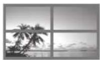

group of 16 (4 × 4) group of 4 (2 × 2) group of 9 (3 × 3)

(see page 35 for more displays lineups.)
Note: Following signals are not applicable to this menu.
1125 / 50p · 60p, 1152 × 864 @60 Hz, 1400 × 1050 @60 Hz, 1600 × 1200 @60Hz, 1920 × 1200 @60 Hz.
How to setup MULTI DISPLAY
1

Press to display the SET UP menu.

2

Press to select the MULTI DISPLAY SETUP.
Press to display the "MULTI DISPLAY SETUP" menu.

![graph TD A["Top"] --> B["Center"] B --> C["Right"] B --> D["Left"] B --> E["Down"] B --> F["Up"] style B fill:#ccc,stroke:#333](/content/2026/05/998345/images/a0291195a92c07497edb6cf09669ae8e6ec8e2ac101a367354cb6de20b68f353.jpg)
Press to select the MULTI DISPLAY SETUP.
Press to select "ON" or "OFF".

How to set the Display location number for each Plasma Display
![graph TD A["Top Left Arrow"] --> B["Center Square"] C["Right Arrow"] --> B D["Bottom Right Arrow"] --> B B --> E["Bottom Left Arrow"]](/content/2026/05/998345/images/4aa13afa9f813ec24962448fe1eb3721726b550a4accbe4b674994c0b4a2c561.jpg)
Press to select HORIZONTAL SCALE.
Press to select "× 1", "× 2", "× 3", "× 4".

![graph TD A["Top"] --> B["Center"] B --> C["Right"] B --> D["Left"] B --> E["Bottom"] B --> F["Square Node"] style B fill:#ccc,stroke:#333](/content/2026/05/998345/images/017dd16b697c73e2ff224c05916487023b16fbb9987b705b2f02e4cadca28e66.jpg)
Press to select VERTICAL SCALE.
Press to select "× 1", "× 2", "× 3", "× 4".

![graph TD A["Top Left Arrow"] --> B["Center Square"] B --> C["Bottom Right Arrow"] C --> D["Bottom Left Arrow"] D --> A style A fill:#ccc,stroke:#333 style B fill:#ccc,stroke:#333 style C fill:#ccc,stroke:#333 style D fill:#ccc,stroke:#333](/content/2026/05/998345/images/bc904b47da4e9f264f7f76455dc7185286c7b2f3b6e2ccfe6e0bdbea1d02e0b8.jpg)
Press to select SEAM HIDES VIDEO.
Press to select "OFF", "ON".

![graph TD A["Top Left Arrow"] --> B["Center Square"] B --> C["Bottom Right Arrow"] C --> D["Right Arrow"] D --> E["Left Arrow"] E --> F["Bottom Left Arrow"]](/content/2026/05/998345/images/2134434f0e98117a1dff77b6807de48aa88f12d2351e6c1b3ee82418bc528893.jpg)
Press to select LOCATION.
Press to select the required arrangement number. (A1-D4 : Refer to the following)

Display Number locations for each arrangement. (Examples)


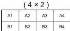
| A1 | A2 | A3 | A4 |
| B1 | B2 | B3 | B4 |
| C1 | C2 | C3 | C4 |
| D1 | D2 | D3 | D4 |
8

Press twice to exit from SET UP.
SEAM HIDES VIDEO Setting
| Reference | To hide joints between TVs. Suitable for moving image display. Suitable for moving image display. | To show joints between TVs. Suitable for still image display. Suitable for still image display. |
| Step 6, Page 35 ON OFF | ||
ID Remote Control Function
You can set the remote control ID when you want to use this remote control on one of several different TVs.
1 Switch to on the right side. 2 Press the button on the remote control. 3 Press one of 1, for the tens digit setting. 4 Press one of 1, for the units digit setting.

Notes:
• The numbers in 2, 3 and 4 should be set up quickly. - Adjustable ID number range is 0 - 99. - If a number button is pressed more than two times, the first two numbers become the ID number for the remote control.
ID remote control button operation
The operation is the same as normal remote control except for the button.
ID Cancellation
Press Ⓗ ALL button on remote control. (This has the same effect as pressing the Ⓗ SET, 0, 0 buttons at the same time.)
Notes:
- Set the Remote ID "On" to operate the ID remote control. If remote ID is set to "On", you can use the remote control without identical ID number during option menu display. (see page 42)
- The ID remote control cannot be used when ID select is set to anything other than 0, and the remote control ID is not the same as the ID select number (see page 42).
SET UP for Input Signals
COMPONENT / RGB IN SELECT
Select to match the signals from the source connected to the COMPONENT / RGB input terminals. Y, PB, PR signals ☐COMPONENT R, G, B, HD, VD signals ☐RGB
1

Press to display the SET UP menu.
2
![graph TD A["Outer Ring"] --> B["Inner Circle"] B --> C["Square Node"] C --> D["Arrow Right"] C --> E["Arrow Left"] C --> F["Arrow Down"] C --> G["Arrow Up"] style A fill:#ccc,stroke:#333 style B fill:#ccc,stroke:#333 style C fill:#ccc,stroke:#333 style D fill:#ccc,stroke:#333 style E fill:#ccc,strok…](/content/2026/05/998345/images/08cb39c5871f9d49deeb65ab201ffa7fa89e0f867c2e8369a09b4318dff5f825.jpg)
Press to select the "COMPONENT / RGB-IN SELECT".
Press to select the desired mode. COMPONENT ←→ RGB
3

Press to exit from adjust mode.


Note:
Selection may not be possible, depending on which optional board is installed.
3D Y/C FILTER – For NTSC AV images
Select "SIGNAL" from the "SET UP" menu during VIDEO (S VIDEO) input signal mode. ("SIGNAL [VIDEO]" menu is displayed.)
1
![graph TD A["Top"] --> B["Center"] B --> C["Right"] B --> D["Down"] B --> E["Left"] B --> F["Square"]](/content/2026/05/998345/images/1ad6c0dd4375481faa59570f4082b9a9f375a2e0b458fa8509fd82d8f2001bdd.jpg)
Press to select the "3D Y/C FILTER (NTSC)".
Press to set ON / OFF.
2
Press to exit from adjust mode.
Note:
When ON, this setting only affects NTSC input signals.


Press ACTION (■) button
![SIGNAL [VIDEO] 3D Y/C FILTER (NTSC) ON COLOR SYSTEM AUTO 3 : 2 PULLDOWN OFF Panasonic AUTO (4 : 3) NORMAL VIDEO NR OFF](/content/2026/05/998345/images/ae9f96c4f1a3a2bb3c1ef97e4c12a014cc05d5eda8502e1cfb14503c5e051a2a.jpg)
COLOR SYSTEM / Panasonic AUTO
Select SIGNAL from the "SET UP" menu during VIDEO (S VIDEO) input signal mode. ("SIGNAL [VIDEO]" menu is displayed.)
![graph TD A["Top"] --> B["Center"] B --> C["Right"] B --> D["Left"] B --> E["Bottom"] B --> F["Right"] style B fill:#ccc,stroke:#333](/content/2026/05/998345/images/fa69de7e49c67465b179f0b6d2163c3dc59ace9c11c3db9d3957250e46d5be35.jpg)
Press to select the "COLOR SYSTEM" or "Panasonic AUTO".
Press to select each function.
If the image becomes unstable:
With the system set to Auto, under conditions of low-level or noisy input signals, the image may in rare cases become unstable. Should this occur, set the system to match the format of the input signal.

↓ Press ACTION (■) button
| Mode Function | |
| COLOR SYSTEM | Set the color system to match the input signal. If set to “AUTO”, the color system is determined automatically.→ AUTO SEGAM M.NTSC NTSCPAL ↔ ← |
| Panasonic AUTO(4:3) | Set to “NORMAL” to view 4:3 images in an unchanged format when Panasonic AUTO is selected. If you would like to view 4:3 images in Just format, set to “JUST”. |
Note:
Panasonic AUTO does not function when TY-FB9BD (BNC Dual Video Terminal Board (option)) is used.
3:2 PULLDOWN: When ON, the display attempts to reproduce a more natural interpretation of sources such as movie pictures, which are recorded at 24 frames per second.
pictures, which are recorded at 24 frames per second.
If the picture is not stable, turn the setting to OFF.
When ON, this setting only affects the following signal input:
When ON, this setting only affects the following signal input:
- 525i(480i) 625i(575i), 1125(1080)/60i signal input during "COMPONENT" input signal.
- 525i (480i), 625i (575i), 1125 (1080)/60i signal input during "COMPONENT" input signal.
VIDEO NR: Automatically reduces unwanted picture noise.
VIDEO NR cannot be adjusted while a PC signal is being applied.
VIDEO NR cannot be adjusted while a PC signal is being applied.

Press the ACTION (■) button.
1
![graph TD A["Top Left Arrow"] --> B["Center Square"] C["Right Arrow"] --> B D["Bottom Right Arrow"] --> B B --> E["Bottom Left Arrow"]](/content/2026/05/998345/images/fe9e5421557cb8c8383e1ca37060e65da7ec3f009976890514f75f0ecaf81d0a.jpg)
Press to select 3:2.
Press to set ON/OFF.

![SIGNAL [ RGB ] SYNC AUTO 3 : 2 PULLDOWN OFF VIDEO NR OFF H-FREQ: 33.8 kHz V-FREQ: 60.0 Hz](/content/2026/05/998345/images/12d153e3c64718cef6b0ea3f191f70eb79c5c7eb8a9071b09e831f0cab5410ad.jpg)
2

Press to exit from adjust mode.


SYNC
Select SIGNAL from the "SET UP" menu during RGB input signal.
1
2


↓ Press ACTION (■) button
Setting RGB sync signal
Confirm that the input is set to RGB INPUT (this setting is valid only for RGB INPUT signal).
AUTO: The H and V sync or synchronized signal are automatically selected. If both are input, the H and V sync is selected.
ON G: Uses a synchronized signal on the Video G signal, which is input from the G connector.
VBS: Uses a synchronized signal of Composite Sync input, which is input from the HD connector.
![graph TD A["SYNC"] --> B["AUTO"] C["SYNC"] --> D["ON G"] E["SYNC"] --> F["VBS"]](/content/2026/05/998345/images/38030a57723d3cf58815f8e928aea63d44dba4e269c44c86ff8372a93f011321.jpg)
H-FREQ. (kHz) / V-FREQ. (Hz)
Displays the H (Horizontal) / V (Vertical) frequencies.
This display is valid only for RGB/PC and Digital input signal.
Display range:
Horizontal 15 - 110 kHz
Vertical 48 - 120 Hz

Options Adjustments
1

Press to display the Setup menu.
2

Press to select "OSD Language".
3

Press and hold until the Options menu is displayed.
4

Press to select your preferred menu.
5
Press to adjust the menu.
Press to confirm.
6

Press to exit from Options menu.

| Options | 1/3 |
| Off-timer function | Enable |
| Onscreen display | On |
| Initial INPUT | Off |
| Initial VOL level | Off 0 |
| Maximum VOL level | Off 0 |
| INPUT lock | Off |
| Studio W/B | Off |
| Advanced PIP | Off |
| Display size | Off |
| Item | Effect | Adjustments | |
| Off-timer function | Enable Disable | Enable: Switches the “Off-timer function” to “On”Disable: Switches the “Off-timer function” to “Off”Note: When “Disable” is set, the Off-timer is cancelled. | |
| Onscreen display | On Off | On: Displays all the following on screen.• Power on display• Input signal switch display• No signal display• Mute and the remaining time of off-timer after ☐ was pressed.Off: Hides all the items above from view. | |
| Initial INPUT | ◀ ▶ | Off ◁PC INPUT1 INPUT2 INPUT3→Adjusts the input signal when TV is turned on.Notes:• Only the adjusted signal is displayed. (see page 18).• Signal can be displayed when the Terminal board is installed.• This menu is available only when “INPUT lock” is “Off”. | |
Options Adjustments
| Options | 1/3 | |
| Off-timer function | Enable | |
| Onscreen display | On | |
| Initial INPUT | Off | |
| Initial VOL level | Off | 0 |
| Maximum VOL level | Off | 0 |
| INPUT lock | Off | |
| Studio W/B | Off | |
| Advanced PIP | Off | |
| Display size | Off | |
| Item | Effect | Adjustments | |
| Initial VOL level | Press button to adjust the volume when TV is turned on.Off←→ OnOff: Sets normal volume.On: Sets your preferred volume.Notes:When “Maximum VOL level” is “On”, the volume can only be adjusted between 0 and your maximum range.You can hear the changed volume regardless of your volume setting before opening the options menu if you adjust the volume when “Initial VOL level” is “On” and cursor is on the menu. | ||
| Maximum VOL level | Press button to adjust the maximum volume.Off←→ OnOff: Sets auto maximum volume.On: Sets your preferred maximum volume.Notes:If the “Maximum VOL level” is set lower than the “Initial VOL level”, the “Initial VOL level” automatically becomes the same as the “Maximum VOL level”.The volume display can go up to 63 regardless of the settings.You can hear the changed volume regardless of your volume setting before opening the options menu if you adjust the volume when “Maximum VOL level” is “On” and cursor is on the menu. | ||
| INPUT lock | Off←→ PC INPUT1 <INPUT2 INPUT3Locks the input switch operation.Notes:Only the adjusted signal is displayed (see page 18).Signal can be displayed when the Terminal board is installed.Input switch can be used when this is set to “Off”.In two screen display mode, if anything other than “Off” is set, the value will be fixed as the value input in the single screen display mode. | ||
| Studio W/B | Off: Nullify all the settings adjusted.On: Sets the color temperature for TV studio.Note: Valid only when the low is set as color temperature on screen adjustment. | ||
| Advanced PIP | Off: Sets normal two screen display mode (see page 22).On: Sets Advanced PIP mode (see page 23).Notes:When “INPUT lock” is “On”, you cannot use all the two screen display functionsütters buttons are unavailable during Advanced PIP mode operation. | ||
| Display size | Adjusts the image display size on screen.Off: Sets the normal image display size on screen.On: Sets the image display size approximately 95 % of the normal image display.O f f O n[IMAGE]Notes:This setting is valid only when the input signals are as follows; 525i, 525p, 625i, 625p, 750/60p, 750/50p, 1125/60i, 1125/50i, 1125/24sF, 1125/25p, 1125/24p, 1125/30p, 1125/50p/60p, 1250/50i (Component Video, RGB, DVI, SDI, HDMI)This setting is invalid when two screen display, digital zoom or Multi screen is selected.When “Display size” is set to “On”, “H-POS” and “V-POS” in “POS. /SIZE” can be adjusted.Refer to each board’s operating instruction for DVI, SDI, HDMI’s corresponding signals. | ||
Options Adjustments
| Options | 2/3 |
| Button lock | Off |
| Remocon User level | Off |
| ID select | 0 |
| Remote ID | Off |
| Serial ID | Off |
| Item | Effect | Adjustments | |
| Button lock | Off←→ MENU&ENTER OnOff: All the buttons at the bottom of the main unit can be used.MENU & ENTER:Locks □ and □ buttons on bottom face of main unit.On: Locks all the button on bottom face of main unit. | ||
| RemoconUser level | Off←→ User1 ←User2 User3Off: You can use all of the buttons on the remote control.User1:You can only use ON, OFF INPUT 1 2 3 PC SURROUND + buttons on the remote control.User2:You can only use ON buttons on the remote control.User3:Locks all the buttons on remote control. | ||
| ID select | Sets panel ID number when panel is used in “Remote ID” or “Serial ID”.Set value range: 0 - 100(Standard value: 0) | 1 2 34 5 67 8 90 | |
| Remote ID | Off On | Off: Disables ID remote control functions. You can use normal remote control operations.On: Enable ID remote control functions. | |
| Serial ID | Off On | Sets the panel ID Control.Off: Disables external control by the ID.On: Enables the external control by the ID. | |
| Options | 3/3 |
| Slot power | Off |
| V. Installation | Off |
| Rotate | Off |
| Serial Slot Select | Slot1 |
| Item | Effect | Adjustments | |
| Slot Power | Off←AutoOnOff:Power is not transmitted to the slot power.Auto:Power is transmitted to the slot power only when main power is on.On:Power is transmitted to the slot power when main power is on or in the standby state.Note:In some cases, power is transmitted to the slot power when main power is on or in the standby state regardless of the slot power setting. | ||
| V.Installation | Off:Sets fan to the horizontal installation mode.On:Sets fan to the vertical installation mode.Notes:This functions when display is turned on.Turn up the power switch for the upward direction when you set Display vertically. | ||
| Rotate | Off:Does not rotate the image.On:Rotates the image 180 degrees. | ||
| Serial Slot Select | Slot1Selects the slot which communicates serial.Note:The setting of an external command can be set only from the fixed serial terminal (see page 11) | ||
Normalization
When both main unit buttons and remote control are disabled due to the "Button lock", "Remocon User level" or "Remote ID" adjustments, set all the values "Off" so that all the buttons are enabled again.
Press the □ button on main unit together with ○ button on the remote control and hold for more than 5 seconds. The "SHIPPING" menu is displayed and the lock is released when it disappears.
Shipping condition
This function allows you to reset the unit to the factory setting.
1


Press to display the SET UP menu.
2

Press to select "OSD LANGUAGE".
3

Press and hold till the SHIPPING menu is displayed.
4

Press to select "YES".
Press to confirm.


[from the unit]
1 Press the MENU button till the Setup menu is displayed. 2 Press the Volume Up "+" or Down "-" button to select "OSD LANGUAGE". 3 Press and hold the ENTER button till the SHIPPING menu is displayed. 4 Press the Volume Up "+" or Down "-" button to select "YES". 5 Press the ENTER button.
Note:
Press the R button to return to SET UP menu when SHIPPING menu is displayed.
Troubleshooting
Before you call for service, determine the symptoms and make a few simple checks as shown below.
| Symptoms | Checks | ||
| Picture Sound | |||
 | Interference No |  | Electrical AppliancesCars / MotorcyclesFluorescent light |
 | Normal Picture |  | Volume(Check whether the mute function has been activated on the remote control.) |
 | No Picture No S |  | Not plugged into AC outletNot switched onPICTURE and BRIGHTNESS/Volume setting(Check by pressing the power switch or stand-by button on the remote control.) |
 | No Picture Norm |  | If a signal with a non-applicable color system format, or frequency is input, only the input terminal indication is displayed. |
 | No Color Norma |  | Color controls set at minimum level. (see page 24, 25)COLOR SYSTEM (see page 38) |
| No remote control operations can be performed. | Check whether the batteries have discharged completely and, if they have not, whether they were inserted properly.Check whether the remote control sensor is exposed to an outdoor light or a strong fluorescent light.Check whether the remote control designed specifically for use with the unit is being used.(The unit cannot be operated by any other remote control.) | ||
| A cracking sound is sometimes heard from the unit. | If there is nothing wrong with the picture or sound, this is the sound of the cabinet undergoing very slight contractions in response to changes in the room temperature. There are no adverse effects on the performance or other aspects. | ||
| The top or bottom of the picture on the screen is cut off when I use the zoom function. | Adjust the position of the picture on the screen. | ||
| Areas at the top and bottom of the screen where the image is missing appear when I use the zoom function. | When using a video software program (such as a cinema size program) with a screen wider than one in the 16:9 mode, blank areas separate from the images are formed at the top and bottom of the screen. | ||
| I can hear sounds coming from inside the unit. | When the power is turned on, a sound of the display panel being driven may be heard: This is normal and not indicative of malfunctioning. | ||
| This Plasma Display uses special image processing. Hence a slight time lag may occur between image and audio, depending on the type of input signal. However, this is not a malfunction. | |||
Plasma Display panel
| Symptoms Check | |
| The screen darkens slightly when bright pictures with minimal movements are shown. | The screen will darken slightly when photos, still images of a computer or other pictures with minimal movements are shown for an extended period. This is done to reduce after-image on the screen and the shortening of the screen's service life: It is normal and not indicative of malfunctioning. |
| It takes a while for the picture to appear. | The unit digitally processes the various signals in order to reproduce esthetically pleasing images. As such, it sometimes takes a few moments for the picture to appear when the power has been turned on, when the input has been switched or when the images for the main picture and sub picture on the two screens are swapped. |
| The edges of the images flicker. | Due to the characteristics of the system used to drive the panel, the edges may appear to flicker in the fast-moving parts of the images: This is normal and not indicative of malfunctioning. |
| The brightness on both sides of images in NORMAL mode changes. | When viewing the side panels at the "BRIGHT" or "MID" setting, the brightness on both sides may change depending on the kind of program shown: This is normal and not indicative of malfunctioning. |
| Some parts of the screen do not light up. | The plasma display panel is manufactured using an extremely high level of precision technology, however, sometimes some parts of the screen may be missing picture elements or have luminous spots. This is not a malfunction. |
 After-images appear After-images appear | Do not allow a still picture to be displayed for an extended period, as this can cause a permanent after-image to remain on the Plasma Display.Examples of still pictures include logos, video games, computer images, teletext and images displayed in NORMAL mode.Note:The permanent after-image on the Plasma Display resulting from fixed image use is not an operating defect and as such is not covered by the Warranty.This product is not designed to display fixed images for extended periods of time. |
| Whirring sounds can be heard from the display unit. | The display unit is fitted with a cooling fan to dissipate heat generated during normal use. The whirring sound is caused by rotation of the fan and is not a malfunction. |
DVI-D/COMPONENT/RGB/PC input signals
Applicable input signals for Component / RGB, Mini D-sub 15P (Component / RGB), DVI-D (* Mark)
| Signal name | Horizontal frequency (kHz) | Vertical frequency (Hz) | Component / RGB / Mini D-sub 15P (Component / RGB) | DVI-D | ||||||
| 1 | 525 | (480) | / | 60i | 15 | 73 | 59.94 | * | ||
| 2 | 525 | (480) | / | 60p | 31 | 47 | 59.94 | * *1 | * | |
| 3 | 625 | (575) | / | 50i | 15 | 63 | 50.00 | * | ||
| 4 | 625 | (575) | / | 50p | 31 | 25 | 50.00 | * | ||
| 5 | 626 | (576) | / | 50p | 31 | 25 | 50.00 | * | ||
| 6 | 750 | (720) | / | 60p | 45 | 00 | 60.00 | * | * | |
| 7 | 750 | (720) | / | 50p | 37 | 50 | 50.00 | * | * | |
| 8 | 1,125 | (1,080) | / 60p | 67.50 | 60.00 | * | * | |||
| 9 | 1,125 | (1,080) | / 60i | 33.75 | 60.00 | * | * | |||
| 10 | 1,125 | (1,080) | / 50p | 56.26 | 50.00 | * | * | |||
| 11 | 1,125 | (1,080) | / 50i | 28.13 | 50.00 | * | * | |||
| 12 | 1,125 | (1,080) | / 24sF | 27.00 | 47.92 | * | ||||
| 13 | 1,125 | (1,080) / 30p | 33.75 | 30.00 | * | |||||
| 14 | 1,125 | (1,080) | / 25p | 28.13 | 25.00 | * | ||||
| 15 | 1,125 | (1,080) | / 24p | 27.00 | 24.00 | * | ||||
| 16 | 1,250 | (1,080) | / 50i | 31.25 | 50.00 | * | ||||
| 17 | 640 × 400 @70 Hz | 31.46 70.07 * | ||||||||
| 18 | 640 × | 480 | @60 | Hz | 31.47 | 59.94 | * *2 | * | ||
| 19 | 640 × | 480 | @72 | Hz | 37.86 | 72.81 | * | |||
| 20 | 640 × | 480 | @75 | Hz | 37.50 | 75.00 | * | |||
| 21 | 640 × | 480 | @85 | Hz | 43.27 | 85.01 | * | |||
| 22 | 800 × 600 @56 Hz | 35.16 56.25 * | ||||||||
| 23 | 800 × 600 @60 Hz | 37.88 60.32 * | ||||||||
| 24 | 800 × 600 @72 Hz | 48.08 72.19 * | ||||||||
| 25 | 800 × 600 @75 Hz | 46.88 75.00 * | ||||||||
| 26 | 800 × 600 @85 Hz | 53.67 85.06 * | ||||||||
| 27 | 852 × | 480 | @60 | Hz | 31.47 | 59.94 | * *2 | * | ||
| 28 | 1,024 × 768 @50 Hz | 39.55 50.00 * | ||||||||
| 29 | 1,024 × 768 @60 Hz | 48.36 60.00 * | ||||||||
| 30 | 1,024 × 768 @70 Hz | 56.48 70.07 * | ||||||||
| 31 | 1,024 × 768 @75 Hz | 60.02 75.03 * | ||||||||
| 32 | 1,024 × 768 @85 Hz | 68.68 85.00 * | ||||||||
| 33 | 1,066 × 600 @60 Hz | 37.88 60.32 * | ||||||||
| 34 | 1,152 × 864 @60 Hz | 53.70 60.00 * | ||||||||
| 35 | 1,152 × 864 @75 Hz | 67.50 75.00 * | ||||||||
| 36 | 1,280 × 960 @60 Hz | 60.00 60.00 * | ||||||||
| 37 | 1,280 × 960 @85 Hz | 85.94 85.00 * | ||||||||
| 38 | 1,280 × 1,024 @60 Hz | 63.98 60.02 * | ||||||||
| 39 | 1,280 × 1,024 @75 Hz | 79.98 75.03 * | ||||||||
| 40 | 1,280 × 1,024 @85 Hz | 91.15 85.02 * | ||||||||
| 41 | 1,366 × 768 @50 Hz | 39.55 50.00 * | ||||||||
| 42 | 1,366 × 768 @60 Hz | 48.36 60.00 * | ||||||||
| 43 | 1,400 × 1,050 @60 Hz | 65.22 60.00 * | ||||||||
| 44 | 1,600 × 1,200 @60 Hz | 75.00 60.00 * | ||||||||
| 45 | 1,600 × 1,200 @65 Hz | 81.25 65.00 * | ||||||||
| 46 | 1,920 × 1,200 @60 Hz | 74.04 59.95 * | ||||||||
| 47 | Macintosh13" (640 × 480) | 35.00 66.67 * | ||||||||
| 48 | Macintosh16" (832 × 624) | 49.72 74.54 * | ||||||||
| 49 | Macintosh21" (1,152 × 870) | 68.68 75.06 * | ||||||||
*1: When the RGB format and 525p signal are input to the Mini D-sub 15P terminal, it is recognized as a VGA 60Hz signal.
*2: When a VGA 60Hz format signal is input from a terminal other than the Mini D-sub 15P terminal, it is recognized as a 525p signal.
Note: Signals that do not meet the above specifications may not be displayed properly.
Specifications
| TH-65PF9UK | ||
| Power Source 120 V AC, 50/6 | 0 Hz | |
| Power Consumption | ||
| Power on 790 W | ||
| Stand-by condition Save OFF 1.0 W, Save ON 0.8 W | ||
| Power off condition 0.1 W | ||
| Plasma Display panel Drive method : AC type 65-inch,16:9 aspect ratio | ||
| Screen size | 56.5" (1,434 mm) (W) × 31.8" (807 mm) (H)× 65" (1,646 mm) (diagonal) | |
| (No.of pixels) 2,073,600 (1,920 (W) × 1,080 (H))[5,760 × 1,080 dots] | ||
| Operating condition | ||
| Temperature 32 °F - 104 °F (0 °C - 40 °C) | ||
| Humidity 20% - 80% | ||
| Applicable signals | ||
| Color System NTSC | PAL, PAL60, SECAM, Modifi ed NTSC | |
| Scanning format | 525 (480) / 60i · 60p, 625 (575) / 50i · 50p, 750 (720) / 60p · 50p, 1125 (1080) / 60i · 50i · 24p · 25p· 30p · 24sF .... SMPTE274M, 1250 (1080) / 50i | |
| PC signals VGA, SVGA, XGA, SXGA,UXGA .... (compressed)Horizontal scanning frequency 15 - 110 kHzVertical scanning frequency 48 - 120 Hz | ||
| Connection terminals | ||
| DVI-D Video Input | DVI-D 24 Pin x 1compliance with DVI Revision 1.0* Refer to page 12 for applicable signalsStereo mini jack (M3) x 10.5VrmsCompatible with HDCP 1.1 | |
| Y/G (BNC)Y or G with/sync 1.0 Vp-p (75 Ω)PB/B (BNC), PR/R (BNC)0.7 Vp-p (75 Ω)AUDIO IN (RCA PIN JACK × 2)0.5 Vrms | ||
Note: Design and specifications are subject to change without notice. Mass and dimensions shown are approximate.
Panasonic Broadcast & Television Systems Company, Unit of Panasonic Corporation of North America
One Panasonic Way 2A-4
Secaucus, NJ 07094
Panasonic Puerto Rico, Inc.
Ave. 65 de Infantería, Km. 9.5
San Gabriel Industrial Park
Carolina, Puerto Rico 00985
PANASONIC PLASMA SCREEN
Limited Warranty
Panasonic Broadcast & Television Systems Company or Panasonic Puerto Rico, Inc. (collectively referred to as "the Warrantor") will repair this product and all included accessories with new or refurbished parts, free of charge in the USA or Puerto Rico, of the original purchase in the event of a defect in materials or workmanship as follows:
| Models or Parts | Part Warranty | Labor Warranty |
| Plasma Screen | 1 Year | 1 Year |
Carry-in or mail-in service in the USA may be obtained during the warranty period by contacting Panasonic Broadcast & Television Systems Company Factory Servicenter listed in the Service Directory or call toll free 1-800-526-6610 to locate an authorized Servicenter.
Carry-in or mail-in service in Puerto Rico can be obtained during the warranty period by calling 787-750-5135.
This warranty is extended only to the original purchaser and is non-transferable. A purchase receipt or other proof of date of original purchase will be required before warranty service is rendered.
This warranty only covers failures due to defects in materials or workmanship, which occur during normal use. The warranty does not cover damage which occurs in shipment, or failures which are caused by products not supplied by the warrantor, or failures which result from installation, set-up adjustments, improper antenna,
inadequate signal pickup, maladjustment of consumer controls, improper operation, power line surge, improper voltage supply, lightning damage, or service by anyone other than an authorized repair facility, or damage attributable to acts of God.
LIMITS AND EXCLUSIONS
There are no express warranties except as listed above.
THE WARRANTOR SHALL NOT BE LIABLE FOR INCIDENTAL OR CONSEQUENTIAL DAMAGES (INCLUDING, WITHOUT LIMITATION, DAMAGE TO DISCS) RESULTING FROM THE USE OF THIS PRODUCT, OR ARISING OUT OF ANY BREACH OF THE WARRANTY. ALL EXPRESS AND IMPLIED WARRANTIES, INCLUDING THE WARRANTIES OF MERCHANTABILITY AND FITNESS FOR PARTICULAR PURPOSE, ARE LIMITED TO THE APPLICABLE WARRANTY PERIOD SET FORTH ABOVE.
Some states do not allow the exclusion or limitation of incidental or consequential damages, or limitations on how long an implied warranty lasts, so the above exclusions or limitations may not apply to you. This warranty gives you specific legal rights and you may have other rights, which vary from state to state.
If you have a problem with this product that is not handled to your satisfaction, then write to the Consumer Affairs Department at the Company address indicated above.
| In the USAFOR THE NEAREST SERVICE CENTER1-800-526-6610Regional Offi ccs | |||
| New Jersey50 Meadowlands Pkwy – 2A4Secaucus, NJ 07094201-348-7975 | Illinois1713 N. Randall – E1-E1Elgin, IL 60123847-468-5270 | Georgia1225 Northbrook PkwySuwanee, GA 30093770-338-6855 | California3330 Cahuenga Blvd WestLos Angeles, CA 90068323-436-3505 |
| In Puerto RicoFor service call 787-750-5135 | |||
Panasonic Canada Inc.
Broadcast & Television Systems Division
5770 Ambler Drive, Mississauga, Ontario L4W 2T3
LIMITED WARRANTY STATEMENT
Panasonic Canada Inc. (also known as PCI) warrants this product to be free of defects in material and workmanship under normal use during the applicable warranty coverage period described below. PCI agrees to repair, or at its option, exchange, any part that becomes defective. However, the product must be purchased and serviced in Canada. The product or part that shows evidence of defect must be delivered prepaid or carried in to an authorized Panasonic Broadcast Service Center. This warranty does not cover shipping costs.
The warranty coverage period is one year for both parts and labor, beginning with the date of original end-user purchase, subject to the exceptions stated below. Repaired or replacement parts supplied during the warranty coverage period carry the unexpired portion of the original warranty coverage period. Proof of product purchase is a condition of warranty service. The owner must produce the product purchase receipt or other satisfactory evidence of the date of original purchase.
This warranty does not apply to external appearance items, such as handles, knobs, safety windows, etc. This warranty does not apply to any part or parts of the product that are installed, altered, repaired, or misused in any way that, in the opinion of PCI, affects the reliability of or detracts from the performance of the product.
For products requiring routine preventive maintenance, that maintenance must be performed in order to maintain warranty coverage.
Serial numbers that have been altered, defaced, or removed void this warranty. This warranty does not cover replacements or repairs necessitated by loss or damage resulting from any cause beyond the control of PCI.
Marking or retained images (sometimes called "burn-in") resulting from the display of fixed images on video display products are not defects and are not covered under this warranty.
THIS EXPRESS, LIMITED WARRANTY IS IN LIEU OF ALL OTHER WARRANTIES, EXPRESS OR IMPLIED, INCLUDING ANY IMPLIED WARRANTIES OF MERCHANTABILITY AND FITNESS FOR A PARTICULAR PURPOSE. IN NO EVENT WILL PANASONIC CANADA INC. BE LIABLE FOR ANY SPECIAL, INDIRECT, OR CONSEQUENTIAL DAMAGES.
In certain instances, some jurisdictions do not allow the exclusion or limitation of incidental or consequential damages, or the exclusion of implied warranties, so the above limitations and exclusions may not be applicable.
WARRANTY COVERAGE PERIOD EXCEPTIONS
| Item | Parts | Labour |
| Video Tape | 30 days—Replacement only (content not covered) | N/A |
| P2 Cards | (Content not covered) | N/A |
| Video Heads | 1 year or 2,000 hrs. (prorated) Whichever comes first | 1 year or 2,000 hrs.Whichever comes first |
| D5 Video heads | 1 year or 500 hrs.Whichever comes first | 1 year or 500 hrs.Whichever comes first |
| Maintenance Items | 90 days | 90 days |
| Colour Camera CCD Imaging Block | 2 years | 1 year |
| LCD/CRT Monitors | 2 years | 1 year |
| * DLP TM Projectors | 3 years or 5,000 hrs.Whichever comes first | 3 years or 5,000 hrs.Whichever comes first |
| * LCD Projectors above 2,500 ANSI Lumens | 3 years or 2,500 hrs.Whichever comes first | 3 years or 2,500 hrs.Whichever comes first. |
| * LCD Projectors below 2,500 ANSI Lumens | 3 years or 1,500 hrs.Whichever comes first | 3 years or 1,500 hrs.Whichever comes first |
| Projector Lamps | 90 Days or 500 hrs.Whichever comes first | 90 Days or 500 hrs.Whichever comes first. |
| Plasma Displays | 1 year (burn-in not covered) | 1 year (burn-in not covered) |
| Hard Drive Disk Unit | 1 year plus balance (if any) of any original Manufacturer's Limited Warranty.(Content not covered) | 1 year |
- Dust, smoke, rental/staging environment, and twenty-four/seven operation dramatically decrease the interval between performances of routine preventive maintenance required to maintain this warranty coverage.
Warranty Service
If the product needs to be shipped for service, carefully pack (preferably in the original carton) and enclose a letter detailing the complaint. Send prepaid and adequately insured to the local authorized Panasonic Broadcast Service Centre in your area or to Panasonic Broadcast & Security Systems Service Department, 5770 Ambler Drive, Mississauga, Ontario, L4W 2T3. Shipping to the latter location requires a return authorization before shipment. No liability is assumed for loss or damage to the product while in transit.
Customer's Record
The model number and serial number of this product can be found on its back cover. You should note this serial number in the space provided below and retain this book, plus your purchase receipt, as a permanent record of your purchase to aid in identification in the event of theft or loss, and for Warranty Service purposes.
Model Number Serial Number
© 2006 Matsushita Electric Industrial Co., Ltd. All Rights Reserved.
Panasonic Broadcast & Television Systems Company
Unit of Panasonic Corporation of North America
Executive Office:
One Panasonic Way 4E-7, Secaucus, NJ 07094 (201) 348-7000
EASTERN ZONE: One Panasonic Way 4E-7 Secaucus, NJ 07094 (201) 348-7621
Mid-Atlantic/New England: One Panasonic Way 4E-7 Secaucus, NJ 07094 (201) 348-7621
Southeast Region: 1225 Northbrook Parkway, Ste 1-160 Suwanee GA 30024 (770)338-6835
Central Region: 1707 N Randall Road E1-C-1, Elgin, IL 60123 (847)468-5200
WESTERN ZONE: 3330 Cahuenga Blvd W., Los Angeles, CA 90068 (323) 436-3500
Dallas Region: 6226 Abington Way, Houston, TX 77008 (713) 802-2726
No. CA/Northwest Region: 5870 Stone Ridge, #3, Pleasanton, CA (925) 416-5108
Government Marketing Department: 52 West Gude Drive, Rockville, MD 20850 (301) 738-3840
Panasonic Canada Inc.
5770 Ambler Drive
Mississauga, Ontario
L4W 2T3
Printed in U.S.A.
MBS0706A0
- PANASONIC®
- OPERATING INSTRUCTIONS
- IMPORTANT SAFETY INSTRUCTIONS
- DEAR PANASONIC CUSTOMER
- TABLE OF CONTENTS
- FCC STATEMENT
- FCC CAUTION
- CANADIAN NOTICE
- NOTE
- TRADEMARK CREDITS
- SAFETY PRECAUTIONS
- CAUTION
- WHEN USING THE PLASMA DISPLAY
- WARNING
- SETUP
- AC POWER SUPPLY CORD
- IF PROBLEMS OCCUR DURING USE
- MAINTENANCE
- ACCESSORIES
- ACCESSORIES SUPPLIED
- REMOTE CONTROL BATTERIES
- REQUIRES TWO AA BATTERIES
- HELPFUL HINT
- PRECAUTION ON BATTERY USE
- CONNECTIONS
- PC INPUT TERMINALS CONNECTION
- NOTES
- SIGNAL NAMES FOR MINI D-SUB 15P CONNECTOR
- SERIAL TERMINALS CONNECTION
- BASIC FORMAT FOR CONTROL DATA
- DVI-D CONNECTION
- COMPONENT / RGB CONNECTION & RGB SIGNAL (R, G, B)
- POWER ON / OFF
- CONNECTING THE PLUG TO THE WALL OUTLET
- BASIC CONTROLS
- SURROUND BUTTON
- INPUT BUTTON
- ASPECT BUTTON
- ON-SCREEN MENU DISPLAYS
- SELECTING THE INPUT SIGNAL
- SELECTING THE ON-SCREEN MENU LANGUAGE
- ASPECT CONTROLS
- ADJUSTING POS. /SIZE
- HELPFUL HINT ( Ⓞ NORMALIZE NORMALIZATION)
- AUTO SETUP
- HELPFUL HINT (NORMALIZE NORMALIZATION)
- MULTI PIP
- INPUT
- ADVANCED PIP
- PICTURE ADJUSTMENTS
- STANDARD
- DYNAMIC
- CINEMA
- SUPER CINEMA
- NORMALIZE
- NORMALIZATION)
- ADVANCED SETTINGS
- SOUND ADJUSTMENT
- MUTE
- DIGITAL ZOOM
- PRESENT TIME SETUP / SET UP TIMER
- PRESENT TIME SETUP
- SET UP TIMER
- SCREENSAVER (FOR PREVENTING AFTER-IMAGES)
- NEGATIVE / SCROLL SELECTION
- MODE SELECTION
- START SETTING
- SETUP OF SCREENSAVER TIME
- REDUCES SCREEN AFTER-IMAGE
- SIDE BAR ADJUST
- REDUCES POWER CONSUMPTION
- CUSTOMIZING THE INPUT LABELS
- SET UP FOR MULTI DISPLAY
- HOW TO SETUP MULTI DISPLAY
- HOW TO SET THE DISPLAY LOCATION NUMBER FOR EACH PLASMA DISPLAY
- DISPLAY NUMBER LOCATIONS FOR EACH ARRANGEMENT. (EXAMPLES)
- SEAM HIDES VIDEO SETTING
- ID REMOTE CONTROL FUNCTION
- ID REMOTE CONTROL BUTTON OPERATION
- ID CANCELLATION
- SET UP FOR INPUT SIGNALS
- COMPONENT / RGB IN SELECT
- D Y/C FILTER – FOR NTSC AV IMAGES
- COLOR SYSTEM / PANASONIC AUTO
- IF THE IMAGE BECOMES UNSTABLE
- WHEN ON, THIS SETTING ONLY AFFECTS THE FOLLOWING SIGNAL INPUT
- VIDEO NR CANNOT BE ADJUSTED WHILE A PC SIGNAL IS BEING APPLIED
- SYNC
- SETTING RGB SYNC SIGNAL
- H-FREQ. (KHZ) / V-FREQ. (HZ)
- DISPLAYS THE H (HORIZONTAL) / V (VERTICAL) FREQUENCIES
- OPTIONS ADJUSTMENTS
- NORMALIZATION
- SHIPPING CONDITION
- TROUBLESHOOTING
- DVI-D/COMPONENT/RGB/PC INPUT SIGNALS
- PANASONIC PLASMA SCREEN
- LIMITED WARRANTY
- LIMITS AND EXCLUSIONS
- PANASONIC CANADA INC
- BROADCAST & TELEVISION SYSTEMS DIVISION
- LIMITED WARRANTY STATEMENT
- WARRANTY SERVICE
- CUSTOMER'S RECORD
- PANASONIC BROADCAST & TELEVISION SYSTEMS COMPANY
- EXECUTIVE OFFICE
Brand : PANASONIC
Model : TH-65PF9UK
Category : Screen