
ARMOR AR3000.2 - Hi-Fi System BOSS - Free user manual and instructions
Find the device manual for free ARMOR AR3000.2 BOSS in PDF.


| Product Type | 2-Channel Car Audio Amplifier |
| Model | ARMOR AR3000.2 |
| RMS Power Output | 300W x 2 @ 4 ohms, 500W x 2 @ 2 ohms |
| Peak Power Output | 1500W peak @ 2 ohms bridged |
| Bridged Power (RMS) | 1000W x 1 @ 4 ohms |
| Frequency Response | 20Hz - 20kHz ±1dB |
| Total Harmonic Distortion (THD) | < 0.05% |
| Signal-to-Noise Ratio | > 90dB |
| Input Sensitivity | 200mV - 8V |
| Load Impedance | 2 ohms - 8 ohms stereo, 4 ohms - 8 ohms bridged |
| Crossover | Variable low-pass (50Hz - 250Hz) and high-pass (50Hz - 500Hz) |
| Bass Boost | 0dB - 18dB @ 45Hz |
| Dimensions (W x H x D) | 13.0 x 2.5 x 11.0 inches |
| Weight | 8.0 lbs |
| Power Supply | 12V DC (10V - 15V) |
| Protection Circuits | Thermal, short circuit, over voltage, under voltage |
| Cooling | Convection cooled with finned heatsink |
| Speaker Outputs | Two sets of binding posts (stereo), one pair (bridged) |
| Input Connections | RCA line inputs, speaker-level inputs (via adapter) |
| Remote Turn-On | Yes (REM terminal) |
| Maintenance | Wipe with dry cloth; keep away from moisture |
| Safety | Install with appropriate fuse; disconnect battery before wiring |
Frequently Asked Questions - ARMOR AR3000.2 BOSS
User questions about ARMOR AR3000.2 BOSS
0 question about this device. Answer the ones you know or ask your own.
Ask a new question about this device
Download the instructions for your Hi-Fi System in PDF format for free! Find your manual ARMOR AR3000.2 - BOSS and take your electronic device back in hand. On this page are published all the documents necessary for the use of your device. ARMOR AR3000.2 by BOSS.
USER MANUAL ARMOR AR3000.2 BOSS



2-Channel MOSFET Amplifiers
| MODEL | AR1200.2 | AR1600.2 | AR2600.2 | AR3000.2 |
| RMS POWERinto 4 Ohms | 230W x 2 | 260W x 2 | 400W x 2 | 480W x 2 |
| MAX POWERinto 2 Ohms | 600W x 2 | 800W x 2 | 1300W x 2 | 1500W x 2 |
| BRIDGED POWERinto 4 Ohms | 1200W x 1 | 1600W x 1 | 2600W x 1 | 3000W x 1 |
| Min. speakerImpedance | 2 Ohm Stereo4 Ohm Mono Bridged | |||
| THD | 0.01% | |||
| Frequency response | 9Hz-50kHz | |||
| Signal-to-noise ratio | >105dB | |||
| Channel separation | 90dB | |||
| Damping factor | 125+ | |||
| Crossover rangelow pass | 35Hz-160Hz | |||
| high pass | fixed, 200Hz | |||
| Bass boost | Variable 0 - +18dB | |||
| Fuse rating | 35A | 25A x 2 | 30A x 2 | 40A x 2 |
| Dimensions: | 10.3"x6.5"x2.8" | 13.1"x6.5"x2.8" | 14.3"x6.5"x2.8" | 18.6"x6.5"x2.8" |
| MODEL | 4-Channel MOSFET Amplifiers | MonoBlock MOSFET Amplifiers | |||
| AR1600.4 | AR2400.4 | AR1500M | AR2000M | AR2500M | |
| RMS POWER into 4 Ohms | 160W x 4 | 240W x 4 | 700W x 1 | 1000W x 1 | 1400W x 1 |
| MAX POWER into 2 Ohms | 400W x 4 | 600W x 4 | 1500W x 1 | 2000W x 1 | 2500W x 1 |
| BRIDGED POWER into 4 Ohms | 800W x 2 | 1200W x 2 | n/a | n/a | n/a |
| Min. speaker impedance | 2 Ohm Stereo4 Ohm Mono Bridged | 2 Ohm Stereo4 Ohm Mono Bridged | 2 Ohm | 2 Ohm | 2 Ohm |
| THD | 0.01% | 0.01% | 0.01% | 0.01% | 0.01% |
| Frequency response | 9Hz-50kHz | 9Hz-50kHz | 9Hz-50kHz | 9Hz-130Hz | 9Hz-130Hz |
| Signal-to-noise ratio | >105dB | >105dB | >105dB | >105dB | >105dB |
| Channel separation | 90dB | 90dB | n/a | n/a | n/a |
| Damping factor | 125+ | 125+ | 125+ | 125+ | 125+ |
| Crossover range low pass | 35Hz-160Hz | 35Hz-160Hz | 35Hz-160Hz | 40 -130Hz/Hz | 40 -130Hz/Hz |
| high pass | fixed, 200Hz | fixed, 200Hz | n/a | n/a | n/a |
| Bass boost | Variable 0 - +18dB | Variable 0 - +18dB | Variable 0 - +18dB | Variable 0 - +12dB | Variable 0 - +12dB |
| Fuse rating | 25A x 2 | 35Ax2 | 30A | 25A x 2 | 30A x 2 |
| Dimensions: | 12.3"x6.5"x2.8" | 16.2"x6.5"x2.8" | 10.3"x6.5"x2.8" | 13.1"x6.5"x2.8" | 16.2"x6.5"x2.8" |
All specifications subject to change without notice.
BOSS® AUDIO SYSTEMS
AR1200.2 AR1600.2 AR2600.2 AR3000.2
Two Channel MOSFET Car Audio Amplifiers
AR1600.4 AR2400.4
Four Channel MOSFET Car Audio Amplifiers
AR1500M AR2000M AR2500M
MonoBlock MOSFET Car Audio Amplifier
Congratulations on your purchase of a BOSS AUDIO SYSTEMS ARMOR Amplifier.
It has been designed, engineered and manufactured to bring you the highest level of performance and quality, and will afford you years of listening pleasure.
Thank you for making BOSS AUDIO SYSTEMS your choice for car audio entertainment!
USER'S MANUAL
page
CONTENTS
2 Introduction
2 What is included?
3 Features
3 About 2 Ohm operation
4 General precautions
4 Installation precautions
4 Mounting the amplifier
5 Connecting the amplifier
6 Low level input wiring
8 High level input wiring
10 2CH Power and Speaker wiring 2CH and Bridged Modes
11 2CH Power and Speaker wiring TriMode
12 4CH Power and Speaker wiring 4CH and Bridged Modes
13 4CH Power and Speaker wiring TriMode
14 MonoBlock Power and Speaker wiring
15 Troubleshooting
16 Specifications
Introduction
With the BOSS ARMOR MOSFET amplifier series, we are introducing nine new amplifiers, all designed in the USA. This new series includes three monoblock amps, four 2-channel, two 4-channel amplifiers.
All ARMOR models feature variable low pass and fixed high pass crossovers and variable input gain controls.
For further flexibility in the use of a subwoofer, 0-+18dB Bass Boost control (2CH/4CH/AR1500M) or 0-+12dB Bass Boost control (AR2000M /AR2500M) has been included on all amplifiers. You can control the subwoofer level with the remote level control module.
BOSS understands that amplifiers are placed in many different kinds of installations, so we incorporated a very flexible system of controls in these amplifiers in order to help you integrate the amp into your system regardless of the nature of your input source.
What is included?
When first unpacking your new amplifier, please check first that the package contains all of the items below. If something is missing, contact the store where you purchased the amplifier.
• ARMOR Amplifier
- Remote subwoofer level control
• High input cable with connector
• Four (4) mounting screws
Troubleshooting
If you experience operation or performance problems with this product, compare your installation with the electrical wiring diagram on the previous pages. If problems persist, read the following troubleshooting tips which may help eliminate the problems.
SYMPTOM
POSSIBLE REMEDY
| Amplifier will not power up. | Check to make sure you have a good ground connection.Check that the Remote Input (Turn-On) has at least 3VDC.Check that there is battery power on the (+) terminal.Check that there is at least 12v.Check all fuses, replace if necessary.Make sure that the Protection LED is not illuminated. If it is lit, shut off the amplifier briefly, and then repower it. |
| Protection LED comes on when amplifier is powered up. | Check for short circuits on speaker leads.Turn down the volume control on the head unit to prevent overdriving.Remove speaker leads, and reset the amplifier. If the Protection LED still comes on, then the amplifier is faulty and needs servicing. |
| No output. | Check that all fuses are OK.Check that amplifier is properly grounded.Check that the Remote Input (Turn-On) has at least 3VDC.Check that the RCA audio cables are plugged into the proper inputs.Check all speaker wiring. |
| Low output. | Reset the Level Control.Check the Crossover Control settings. |
| Audio present in only one channel. | Check the RCA interconnect cables.Check all speaker wiring. |
| High hiss in the speakers. | Disconnect all RCA inputs to the amplifiers. If the hiss disappears, then plug in the component driving the amplifier and unplug its inputs. If the hiss disappears at this point, go on until the faulty/noisy component is found.It is best to set the amplifier's input level control as low as possible. The best subjective signal-to-noise ratio is achieved in this manner. Try to set the head unit as high as possible (without distortion) and the amp input level as low as possible. |
| Squealing noise from speakers. | Check for improperly grounded RCA interconnects. |
| Distorted sound. | Check that the Input Level Control is set to match the signal level of the head unit. Always try to set the Input Level as low as possible.Check that all crossover frequencies are properly set.Check for short circuits on the speaker leads. |
| Amplifier gets very hot. | Check that the minimum speaker impedance for the amp model is correct.Check that there is good air circulation around the amp. In some applications, it may be necessary to add external cooling fan(s). |
| Engine noise (static type) | This is usually caused by poor quality RCA cables,which can pick up radiated noise. Use only the best quality cables, and route them away from power cables. |
| Engine noise (alternator whine) | Check that speaker leads are not shorted to the vehicle chassis.Check that the RCA grounds are not shorted to the vehicle chassis.Check that the head unit is properly grounded. |
Power and Speaker Wiring
MonoBlock Mode
Monoblock Amplifiers AR1500M, AR2000M, and AR2500M
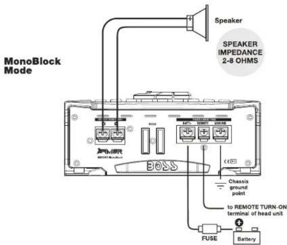
Features
Your new ARMOR ARMOR features the following:
• Class A-B operation
- Bridgeable outputs (except AR1500M, AR2000M and AR2500M)
• Tri-Mode capable (except AR1500M, AR2000M and AR2500M)
• MOSFET PWM (Pulse Width Modulated) Power Supply
• 2 Ohm stable operation with output power increase
• Thermal and speaker short protection
- Soft turn-on circuit
- Remote turn-on/turn-off circuit
• Variable input gain control
• Variable low pass crossover(s)
• Fixed high pass crossover(s) (except AR1500M, AR2000M and AR2500M)
• Variable 0 to +18dB Bass Boost (0 to +12dB for AR2000M/AR2500M)
- Nickel-plated RCA low level and high level inputs
• LED power and protection indicators
• Gun metal gray anodized heatsink
- Remote subwoofer level control
About 2 Ohm operation
Your amplifier has been designed to operate efficiently at loads down to 2 Ohms. This means that you can install four 8 Ohm speakers per channel, when using parallel wiring.
Doubling the number of woofers produces an acoustic coupling effect. This acoustic coupling effect increases the output by about 3dB for each doubling of the number of woofers.
When operating at 2 Ohms, the amplifiers will increase their output power by approximately 50%. The current draw will also increase by about the same amount, so be sure you have enough current to run the amplifiers into a 2 Ohm load.
If you lack adequate current, your music reproduction will be distorted.
General precautions
Before installing and using your new BOSS amplifier, please become familiar with all the information contained in this manual.
Please keep this manual in a safe place for future reference.
- Do not open or attempt to repair this unit yourself. Dangerous high voltages are present which may result in electric shock. Refer any repairs to a qualified service technician.
- To avoid risk of electronic shock or damage to the amplifier, do not permit any of this equipment to become damp or wet from water or drinks. If this does occur, immediately unplug the power wires and send the amplifier to your local dealer or service center as soon as possible.
- If there is smoke or any peculiar odor present during use or if there is damage to any of the component enclosures, immediately unplug the power wire and send the amplifier to your local dealer or service center as soon as possible.
Installation precautions
Before you drill or cut any holes, investigate your car's layout very carefully. Take special care when you work near the gas tank, fuel lines, hydraulic lines and electrical wiring.
Never operate the amplifier when it is unmounted. Attach all audio system components securely to prevent damage, especially in an accident.
Before making or breaking power connections in your system, disconnect the vehicle battery. Confirm that your head unit or other equipment is turned off while connecting the input jacks and speaker terminals.
If you need to replace the power fuse, replace it only with a fuse identical to that supplied with the amplifier. Using a fuse of a different type or rating may result in damage to your audio system or your amplifier which is not covered by the manufacturer's warranty.
Mounting the amplifier
- Find a suitable location in the vehicle in which to mount the amplifier.
- Make sure there is sufficient air circulation around the intended mounting location.
- Mark the location for the mounting hole screws by positioning the amplifier where you wish to install it. Use a scribe or mounting screw, inserted through each of the amp's mounting holes, to mark the mounting surface. If the mounting surface is carpeted, measure the hole centers and mark with a felt tip pen.
- Drill pilot holes in the mounting surface for the mounting screws. Place the amplifier in position, and attach the amplifier to the mounting surface securely using screws.
SHOCK HAZARD! Do not open the case of this product. There are dangerous voltages present within the unit. There are no user-serviceable parts within the unit.
Power and Speaker Wiring
Tri-Mode
4-Channel Amplifiers
AR1600.4 and AR2400.4
Tri-mode operation allows you to connect this amplifier to a pair of main speakers plus a subwoofer on one pair of output channels. The main speakers will operate in STEREO while the subwoofer simultaneously operates in MONO.
To set up the amplifier to run in this mode, put the crossover switches in the FULL position. Insert high pass filter capacitors and a low pass filter inductor into the wiring as shown below. Be sure to check the table at the bottom of this page to determine the correct capacitor and inductor values for the crossover frequency you wish to achieve.
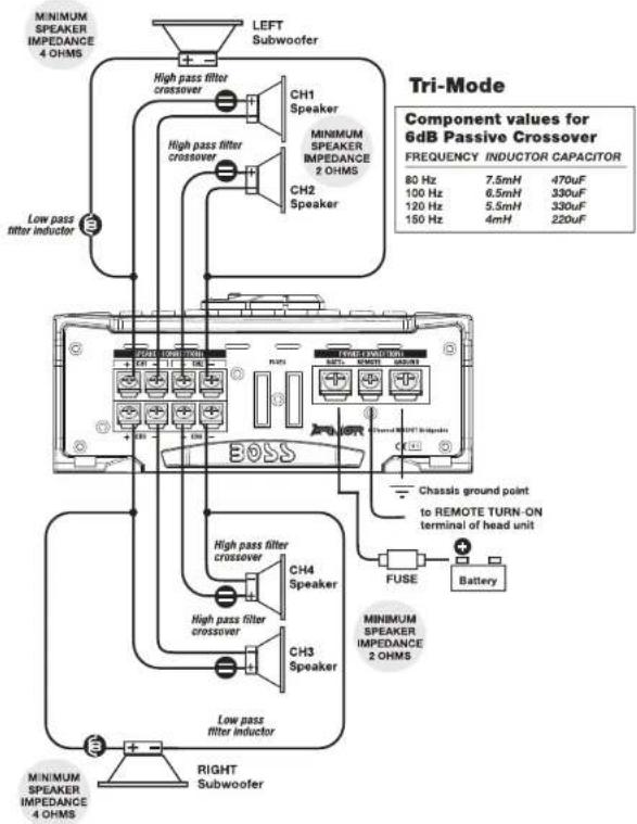
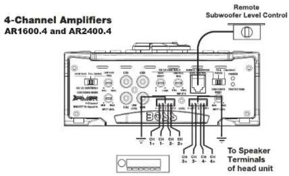
Power and Speaker Wiring
4 Channel and Bridged Modes
4-Channel Amplifiers
AR1600.4 and AR2400.4
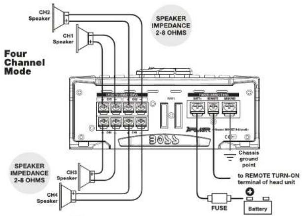
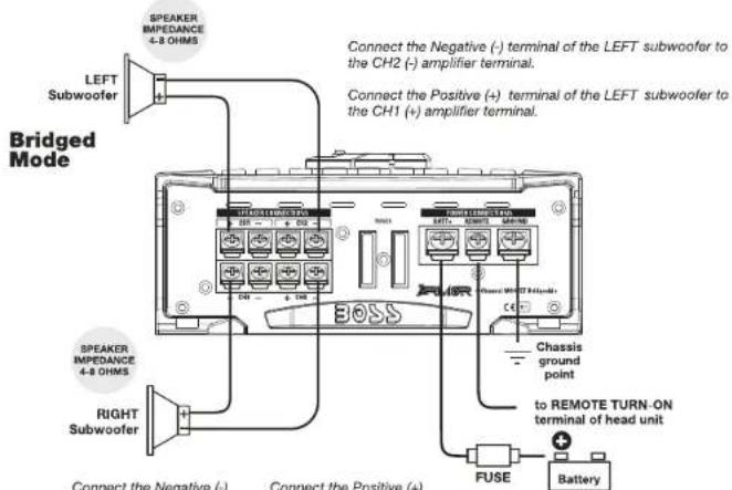
Connect the Negative (-) terminal of the RIGHT subwoofer to the CH4 (-) amplifier terminal.
Connect the Positive (+) terminal of the RIGHT subwoofer to the CHS (+) amplifier terminal.
ARMOR AMPLIFIER Amplifier User's Manual - page 12
Connecting the amplifier
Before doing any wiring, look through this manual and identify the diagrams to follow for power, input and speaker connections for your particular installation. Be sure you understand all the connections before you proceed.
-
Connect the power ground terminal to the closest point on the chassis of the car. Keep this ground wire to less than 39" (100 cm) in length. Use 8 gauge (or heavier) wire.
-
Connect the remote terminal to the remote output of the head unit using 16 gauge (or heavier) wire.
-
Connect an empty fuse holder within 18" (45 cm) of the car battery, and run 8 gauge (or heavier) cable from this fuse to the amplifier location.
-
Check that the fuse holder is empty. Then connect the fuse holder to the "BATT+" connection on the amplifier.
-
If multiple amplifiers are being used in your system, either:
- Run a separate pair of cables from the battery and a chassis ground point to each amplifier. Each (+) cable must have its own inline fuse.
- Run a #4 cable from the fuse holder at the battery to a distribution block at or near the amplifier's location. Then run separate cables from the amplifier to this distribution block and to independent chassis ground points.
-
Connect all line inputs and outputs (if used) using high-quality cables. Connect all speakers, following the diagrams in this manual. Be sure to observe proper polarity to avoid audio phase problems.
-
Insert fuse(s) into the battery fuse holder(s).
- Recheck all connections before powering up the amplifier.
- Set all level controls to minimum position, and set all crossover controls/switches to the desired frequency points.
- Power up the head unit and the amplifier. Then set the volume control on the head unit to about 3/4 volume, and adjust the amplifier's input level control(s) to just below the level of distortion.
- Further fine tuning of the various controls may be necessary to obtain best results.
Don't misuse the level control!
Do not mistake the input level control for a volume control! It is designed ONLY to match the output level of your audio source to the input level of your amplifier.
Do not adjust this input level to maximum unless your input level requires it.
Ignoring these instructions will result in an input overload to the amplifier, and excessive audio distortion. It can also cause the protection circuit to engage.
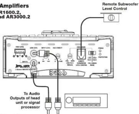
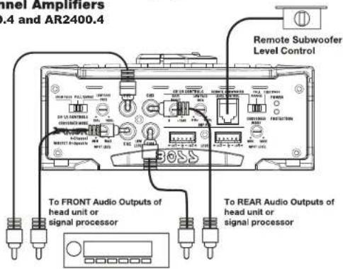
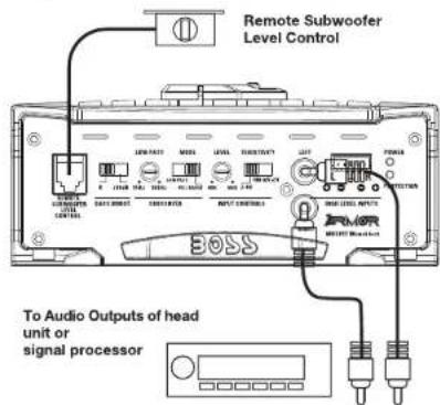
Low Level Input Wiring
Low-level (RCA) input wiring is preferred for best audio performance. Always use a high-quality RCA cable for best audio performance.
NOTE: Do not connect BOTH the high level and low level inputs from your receiver to your amplifier at the same time!
2-Channel Amplifiers
AR1200.2, AR1600.2, AR2600.2, and AR3000.2
4-Channel Amplifiers
AR1600.4 and AR2400.4
ARMOR AMBIOR Amplifier User's Manual - page 6
Power and Speaker Wiring
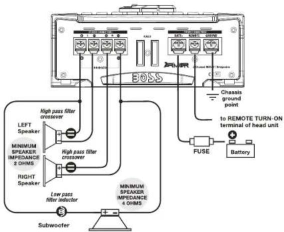
Tri-Mode
2-Channel Amplifiers
AR1200.2, AR1600.2
AR2600.2, and AR3000.2
Tri-mode operation allows you to connect this amplifier to a pair of main speakers plus a subwoofer on one pair of output channels. The main speakers will operate in STEREO while the subwoofer simultaneously operates in MONO.
To set up the amplifier to run in this mode, put the crossover switches in the FULL position. Insert high pass filter capacitors and a low pass filter inductor into the wiring as shown below. Be sure to check the table at the bottom of this page to determine the correct capacitor and inductor values for the crossover frequency you wish to achieve.
| Component values for 6dB Passive Crossover | ||
| FREQUENCY | INDUCTOR | CAPACITOR |
| 80 Hz | 7.5mH | 470uF |
| 100 Hz | 6.5mH | 330uF |
| 120 Hz | 5.5mH | 330uF |
| 150 Hz | 4mH | 220uF |
Tri-Mode
MOSFET Amplifier User's Manual · page 11
Power and Speaker Wiring
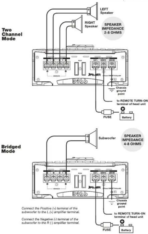
2 Channel and Bridged Modes
2-Channel Amplifiers
AR1200.2, AR1600.2
AR2600.2, and AR3000.2
ARMOR AMPLIFIER Amplifier User's Manual - page 10
Low Level Input Wiring
Low-level (RCA) input wiring is preferred for best audio performance. Always use a high-quality RCA cable for best audio performance.
NOTE: Do not connect BOTH the high level and low level inputs from your receiver to your amplifier at the same time!
MonoBlock Amplifier
AR1500M
MonoBlock Amplifiers
AR2000M and AR2500M
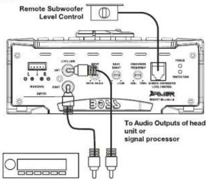
MOSFET Amplifier User's Manual • page 7
High Level Input Wiring
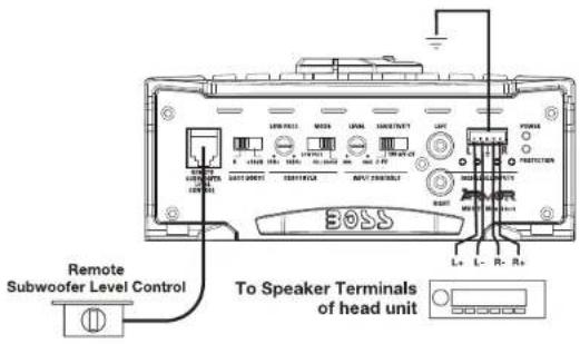
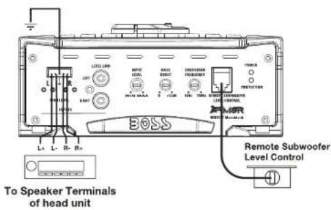
The high level input(s) should only be used when your head unit lacks RCA outputs. If the RCA outputs are not present, connect the speaker outputs from the receiver to the high level input connector of the amplifier. Be sure to observe polarity to avoid audio phase problems.
NOTE: Do not connect BOTH the high level and low level inputs from your receiver to your amplifier at the same time!
2-Channel Amplifiers
AR1200.2, AR1600.2, AR2600.2, and AR3000.2
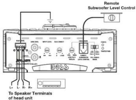
ARMOR RABOR Amplifier User's Manual - page 8
High Level Input Wiring
The high level input(s) should only be used when your head unit lacks RCA outputs. If the RCA outputs are not present, connect the speaker outputs from the receiver to the high level input connector of the amplifier. Be sure to observe polarity to avoid audio phase problems.
NOTE: Do not connect BOTH the high level and low level inputs from your receiver to your amplifier at the same time!
MonoBlock Amplifier
AR1500M
MonoBlock Amplifiers
AR2000M and AR2500M
MOSFET Amplifier User's Manual • page 9
- BOSS® AUDIO SYSTEMS
- Congratulations on your purchase of a BOSS AUDIO SYSTEMS ARMOR Amplifier.
- USER'S MANUAL
- page
- CONTENTS
- Introduction
- What is included?
- Troubleshooting
- Power and Speaker Wiring
- Monoblock Amplifiers AR1500M, AR2000M, and AR2500M
- Features
- About 2 Ohm operation
- General precautions
- Installation precautions
- Mounting the amplifier
- 4-Channel Amplifiers
- AR1600.4 and AR2400.4
- Connecting the amplifier
- Don't misuse the level control!
- Low Level Input Wiring
- High Level Input Wiring
- 2-Channel Amplifiers
- MonoBlock Amplifier
- MonoBlock Amplifiers
Brand : BOSS
Model : ARMOR AR3000.2
Category : Hi-Fi System