
M2605 - Water heater MIDEA - Free user manual and instructions
Find the device manual for free M2605 MIDEA in PDF.


| Product Type | Electric Water Heater |
| Model | Midea M2605 |
| Capacity | 30 Liters |
| Dimensions (WxDxH) | 400 mm x 400 mm x 600 mm |
| Net Weight | 15 kg |
| Power Supply | 220-240 V ~ 50/60 Hz |
| Rated Power | 1500 W |
| Temperature Range | 30°C to 75°C |
| Energy Efficiency Class | A |
| Max Working Pressure | 8 bar |
| Safety Features | Overheat protection, Pressure relief valve, Anti-dry heating protection |
| Installation Type | Wall-mounted vertical |
| Water Connection | 1/2 inch BSP |
| Material | Enamel coated steel tank with magnesium anode |
| Maintenance | Replace magnesium anode every 2 years; descale annually |
| Cleaning | Wipe exterior with damp cloth; do not use abrasive cleaners |
| Spare Parts | Anode rod, thermostat, heating element, pressure relief valve |
| Repairability | Repairable by qualified technician; spare parts available |
| Warranty | 2 years on tank, 1 year on electrical components |
| Certifications | CE, RoHS |
Frequently Asked Questions - M2605 MIDEA
User questions about M2605 MIDEA
0 question about this device. Answer the ones you know or ask your own.
Ask a new question about this device
Download the instructions for your Water heater in PDF format for free! Find your manual M2605 - MIDEA and take your electronic device back in hand. On this page are published all the documents necessary for the use of your device. M2605 by MIDEA.
USER MANUAL M2605 MIDEA
Continuous Flow Gas Water Heater
Installation And Operation Guide
MODELS:
M2005
M2005-50
M2605
M2605-50
FOR EXTERNAL INSTALLATION ONLY
1. IMPORTANT NOTES ......2
1.1. INSTALLATION NOTES ......2
1.2. SERVICE NOTES ...... 2
1.3. PLUMBING NOTES ......2
2. SPECIFICATION ....4
3. INTRODUCTION 5
3.1. DIMENSIONS AND CONNECTION POINTS (M20) 6
3.2. DIMENSIONS AND CONNECTION POINTS (M2605) .....7
3.3.SAFETY GUIDELINES....8
3.4. GENERAL GUIDELINES....8
4. INSTALLATION 9
4.1. CONFIRM THE APPLIANCE SUITABILITY ......9
4.2. SELECTING A SUITABLE LOCATION FOR INSTALLATION ....10
4.3. CLEARANCES FOR OUTDOOR HEATER LOCATIONS .....11
4.4. GAS CONNECTION....12
4.5. SIZING AND CONNECTION SUITABILITY ......12
4.6. MEASURING INLET GAS PRESSURE AND TESTING GAS LEAKAGE....13
4.7. WATER CONNECTIONS 14
4.8. ELECTRICAL CONNECTIONS....14
5. REMOTE CONTROLLER ....15
5.1. REMOTE CONTROLLER INSTALLATION 16
5.2. CONNECTION OF REMOTE CONTROLLER WIRING TO THE WATER HEATER....17
8.6. WATER FLOW AND WATER TEMPERATURE (M20) 30
8.7. WATER FLOW AND WATER TEMPERATURE (M2605) 30
9. M-SMART LIFE APP....31
9.1. INSTALLATION OF WI-FI MODULE (WITHOUT REMOTE CONTROLLER) ....32
9.2. INSTALLATION OF WI-FI MODULE (WITH REMOTE CONTROLLER)....32
9.3. USING YOUR APPLIANCE WITH THE M-SMART LIFE APP....34
1. IMPORTANT NOTES
This manual has been prepared for the relevant licensed professionals of the equipment. Please keep it in a safe place for future reference.
1.1 INSTALLATION NOTES
The installation must be done in accordance with the information supplied in this manual. All other relevant national, state and local regulations must also be adhered to including (but are not limited to):
- Australian Standard AS3500.1 – Water Services.
- Australian Standard AS3500.4 – Heated Water Services.
- Australian Standard AS3000 – Electrical Installation.
- Australian Standard AS/NZS5601 – Gas Appliance Installation.
- Local Water, Gas & Electrical Authority Regulations.
- Municipal Building Codes including local OH&S requirements.
1.2 SERVICE NOTES
Maintenance and fault-finding must be done in accordance with these instructions and the applicable regulations listed above.

WARNING
Installation and service must be performed by a licensed professional (for example, a licensed plumber or gas fitter).
The outlet intended to deliver heated water to sanitary fixtures used primarily for personal hygiene purposes.
1.3 PLUMBING NOTES
PLEASE NOTE M2005 and M2605 models are Nominal 70°C maximum outlet water temperature to comply with the requirements of AS 3498 Clause 7.2.2
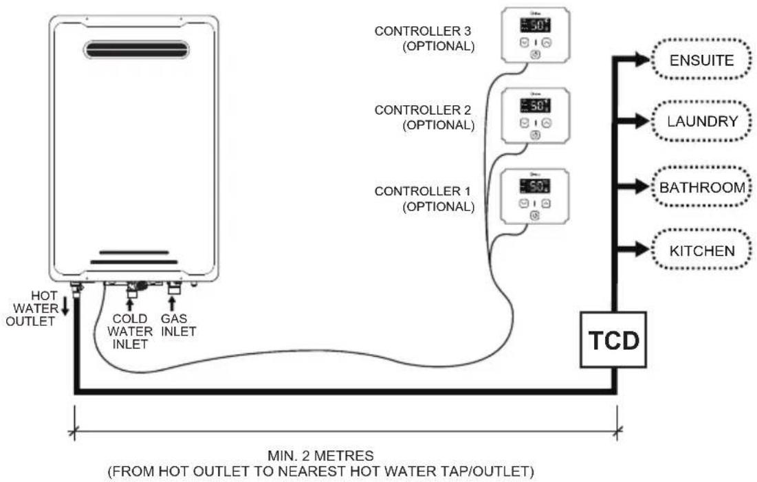
The M2005 and M2605 unit REQUIRES a temperature control device to be installed.
The M2005 and M2605 unit preset temperature is 55^ C.
PLEASE NOTE M2005-50 and M2605-50 model is supplied factory pre-set at Nominal 50°C maximum outlet water temperature(dip switch preset temperature as 48°C) to comply with the requirements of AS 3498 Clause 7.2.1.
The M2005-50 and M2605-50 unit DOES NOT REQUIRE a temperature control device to be installed.
Please follow all the instructions in the Installation Guide and the following additional instructions for the water heater outlet connection.
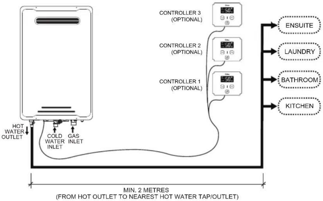
- When connecting the hot water supply to the fixtures of the property a minimum of two (2) metres of pipework must be used between the outlet of the water heater and the first tap / outlet. (See Diagram on following page).
- The hot water line should be insulated with Armaflex or similar pipe insulation.
- When the installation is completed the temperature is to be tested at the taps to confirm the water temperature does not exceed the required 50°C setting.
- Water pipe size is nominal 15mm from hot water outlet to the first tap / outlet.
• Gas pipe size is nominal 20mm.
flowchart
graph TD
    A["Hot Water Outlet"] --> B["COLD WATER INLET"]
    B --> C["Gas INLET"]
    C --> D["COLT WATER INLET"]
    D --> E["CONTROLLER 1 (OPTIONAL)"]
    E --> F["50°C"]
    E --> G["50°C"]
    E --> H["50°C"]
    H --> I["CONTROLLER 2 (OPTIONAL)"]
    I --> J["50°C"]
    I --> K["50°C"]
    K --> L["CONTROLLER 3 (OPTIONAL)"]
    L --> M["50°C"]
    L --> N["50°C"]
    N --> O["ENSUITE"]
    N --> P["LAUNDRY"]
    N --> Q["BATHROOM"]
    N --> R["KITCHEN"]
    style A fill:#f9f,stroke:#333
    style B fill:#ccf,stroke:#333
    style C fill:#cfc,stroke:#333
    style D fill:#fcc,stroke:#333
    style E fill:#cff,stroke:#333
    style F fill:#ffc,stroke:#333
    style G fill:#ffc,stroke:#333
    style H fill:#ffc,stroke:#333
    style I fill:#ffc,stroke:#333
    style J fill:#ffc,stroke:#333
    style K fill:#ffc,stroke:#333
    style L fill:#ffc,stroke:#333
    style M fill:#cfc,stroke:#333
    style N fill:#cfc,stroke:#333
    style O fill:#cfc,stroke:#333
    style P fill:#cfc,stroke:#333
    style Q fill:#cfc,stroke:#333
    style R fill:#cfc,stroke:#333
50°C PRESET UNIT
WARNING — THIS APPLIANCE MUST ONLY BE INSTALLED IN ACCORDANCE WITH THE ACCEPTABLE PLUMBING CONFIGURATIONS SPECIFIED IN THESE INSTRUCTIONS. FAILURE TO DO SO MAY RESULT IN CONDITIONS WHERE DELIVERY TEMPERATURE CONTROL IS INADEQUATE.
THIS APPLIANCE DELIVERS WATER NOT EXCEEDING 50 °C IN ACCORDANCE WITH AS 3498. For 50 °C-limited water heaters with multiple outlets, identification of the outlet intended to deliver heated water to sanitary fixtures used primarily for personal hygiene purposes.
flowchart
graph TD
    A["HVAC System"] --> B["Controller 1 (OPTIONAL)"]
    A --> C["Controller 2 (OPTIONAL)"]
    A --> D["Controller 3 (OPTIONAL)"]
    B --> E["TCD"]
    C --> E
    D --> E
    E --> F["ENSUITE"]
    E --> G["LAUNDRY"]
    E --> H["BATHROOM"]
    E --> I["KITCHEN"]
    J["HOT WATER OUTLET"] --> A
    K["COLD WATER INLET"] --> A
    L["GAS INLET"] --> A
    M["MIN. 2 METRES (FROM HOT OUTLET TO NEAREST HOT WATER TAP/OUTLET)"] --> A
70°C PRESET UNIT (NOTE: TCD - TEMPERATURE CONTROL DEVICE)
WARNING —
THIS APPLIANCE MAY DELIVER WATER AT HIGH TEMPERATURE. REFER TO THE PLUMBING CODE OF AUSTRALIA (PCA), LOCAL REQUIREMENTS AND INSTALLATION INSTRUCTIONS TO DETERMINE IF ADDITIONAL DELIVERY TEMPERATURE CONTROL IS REQUIRED.
2. SPECIFICATIONS
TECHNICAL DATA AND DIMENSIONS
| MODEL | M2005/M2005-50 M2605/M2605-50 | |||
| Gas Type | Natural Gas | ULPG | Natural Gas | ULPG |
| Gas Input (MJ/h) | 160 | 200 | ||
| Inlet Pressure (kPa) | 1.13 - 2.75 | 2.75 - 4.00 | 1.13 - 2.75 | 2.75 - 4.00 |
| Main Injector (mm) | φ1.65 φ | 0.96 | φ1.8 | φ1.3 |
| Test Point Pressure High/Low (kPa) | 0.87/0.18 1 | 92/0.18 | 0.83/0.21 0 | 92/0.27 |
| Water Heating Capacity (At 25°C Rise) | 20L/min | 26L/min | ||
| Max. Water Pressure (kPa) | 1000 | |||
| Min. Water Pressure (kPa) | 150 | |||
| Relief Valve Pressure Setting (kPa) | 1200 | |||
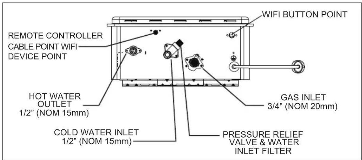
| Gas Connection | 3/4" (Nom 20mm) | |||
| Water Connections | 1/2" (Nom 15mm) | |||
| Ingress Protection Rating (AS60529): | IPX4 | |||
| Ignition | Electronic | |||
| Rated Voltage: | AC.240V/50Hz | |||
| Net Weight (kG) | 15.4 | 19.2 | ||
| Gross Weight (kG) | 16 | 21.5 | ||
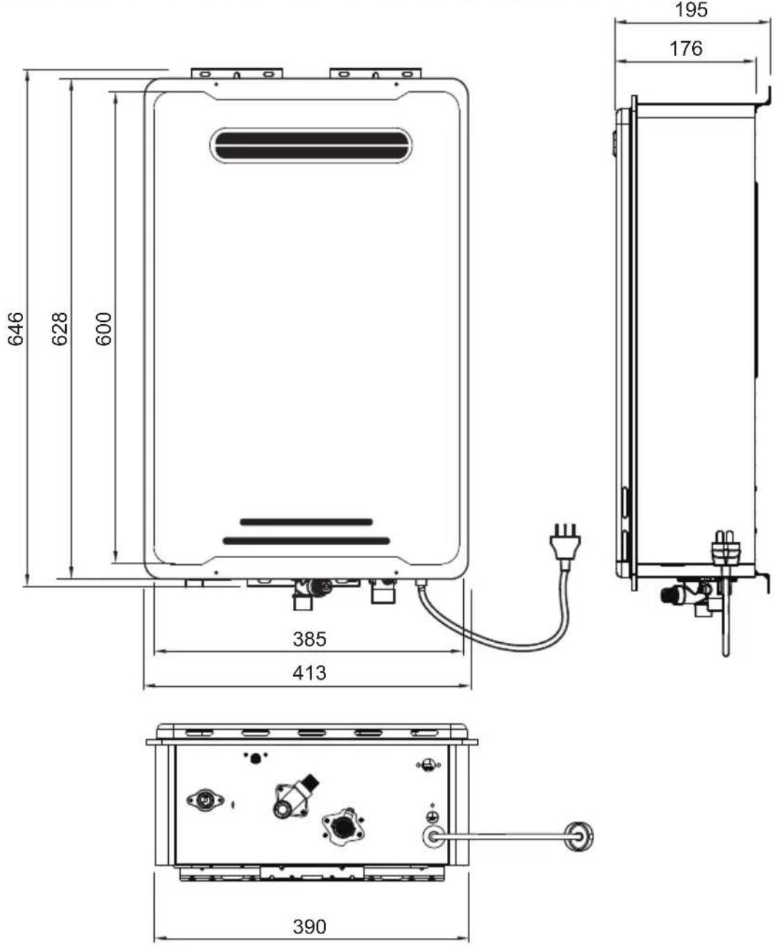
| Product Dimensions (mm) | 595 x 375 x 165 | 628 x 413 x 177 | ||
| Package Dimensions (mm) | 748 x 420 x 230 | 735 x 455 x 267 | ||
| IAPMO Gas Mark Approval Number: | GMK10177 | |||
| IAPMO Water Mark Approval Number: | WM-022451 | |||

NOTES
- The appliance will operate at reduced performance below 340 kPa water pressure.
- For information relating to burner test point pressures and injector sizes refer to the name plate located on the right hand side of the case for each model. (please refer to p.9)
-
For information relating to overall dimensions and connection points refer to diagrams. (Please refer to p.6 & 7)
• Installing in areas over 1500 m above sea level will reduce performance. -
Do not spray aerosols in the vicinity of this appliance while it is inoperation.
- Do not use or store flammable materials in or near this appliance.
- Do not place articles on or against this appliance.
• Do not modify this appliance
3. INTRODUCTION
- This manual provides information necessary for the installation, operation, and maintenance of the water heater.
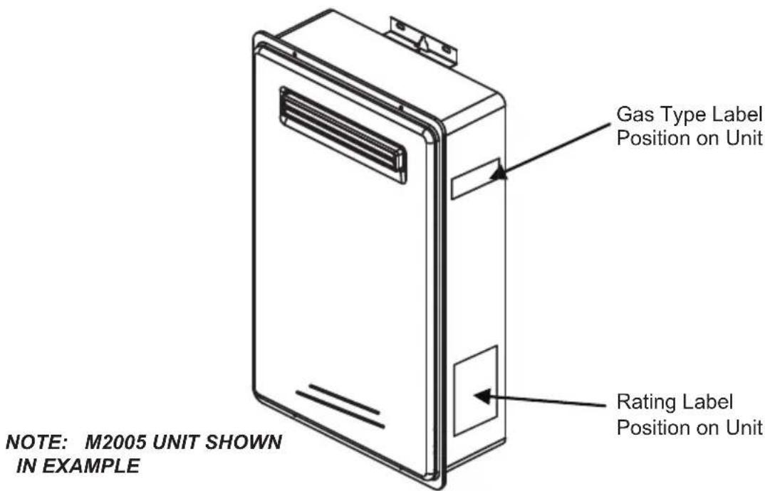
- The model description is listed on the name plate which is attached to the right side of the case of the water heater. (Please refer to p.9)
Please read all installation instructions completely before installing this product. ●
- The Water Heater is an instantaneous, water heater designed to efficiently supply endless hot water on demand.
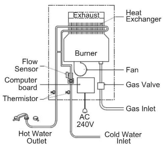
The principle of the water heater is shown below: ●
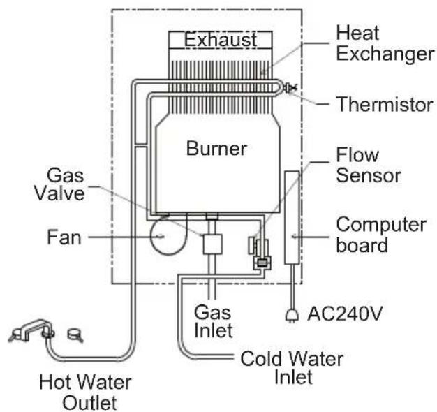
M2005/M2005-50 UNIT M2605/M2605-50 UNIT
The diagrams are representative only and do not truly represent the physical product.
- A hot water tap is turned on.
- Water enters the water heater via the cold water inlet.
- The water flow sensor detects the water flow.
- The computer automatically ignites the burner.
- Water circulates through the heat exchanger and is heated
- The computer will modulate the gas supply valve and water flow to produce the right amount of hot water at the correct temperature.
- When the tap is turned off, the unit shuts down.
3.1 DIMENSIONS AND CONNECTION POINTS (M2005/M2005-50)
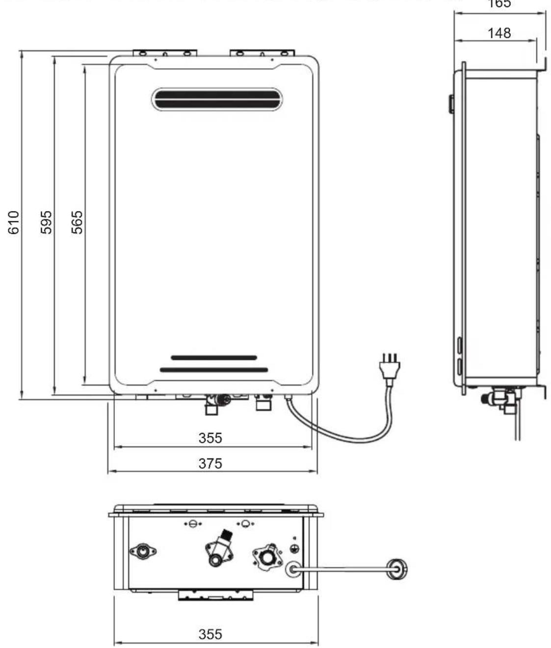
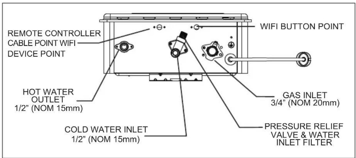
3.2 DIMENSIONS AND CONNECTION POINTS (M2605/M2605-50)
3.3 SAFETY GUIDELINES
Ensure the following warnings and instructions are read and understood before commencing installation.

WARNING
- Installation and service must be performed by a licensed professional (for example, a licensed plumber or gas fitter).
- The licensed professional is responsible for the correct installation of the water heater and for compliance with all relevant national, state and local regulations.
- The water heater must be installed OUTDOORS ONLY. DO NOT install water heater indoors.
• Not to be used as a pool heater.
3.4 GENERAL GUIDELINES
- Carefully plan where you intend to install the water heater.
Please ensure: The water heater has adequate space for natural ventilation; Is located where water leakage will not damage surrounding areas Has all transit protection/packaging removed. - Check the name plate and gas type label for the correct GAS TYPE, GAS PRESSURE, WATER PRESSURE and ELECTRIC RATING; If this unit does not match operating condition, do not install and consult with your supplier.
- If any problem should occur, turn off the gas, all hot water taps and call a licensed professional

WARNING
- Water temperatures above 50°C can cause severe burns or death from scalding. Children, the disabled and the elderly are at a high risk of being injured. Feel the water temperature before bathing or showering. Do not leave children, disabled persons, or the elderly unsupervised. The Australian Standards AS 3498 gives full details of the requirements for supply of controlled temperatures to ablution outlets (bathrooms) and is required to conform to all plumbing codes within Australia.

PROHIBITED
- Do not store or use gasoline or other flammables, vapors, or liquids in the vicinity of this appliance. Vapors from flammable liquids will explode and catch fire causing death or severe burns.
- Do not reverse the water and/or gas connections as this will damage the gas valves and can cause severe injury or death. Follow the diagram on p. 6 & 7 when installing your water heater.
- Do not use this appliance if any part has been in contact with or been immersed in water. Immediately call a licensed professional to inspect and/or service the unit if necessary.
- Do not disconnect the electrical supply if the ambient temperature will drop below freezing. The Freeze Prevention System only works if the unit has electrical power. The warranty will not be covered if the heat exchanger is damaged due to freezing. Refer to the section on the Freeze Prevention System on p. 19 for more information.
4. INSTALLATION
The water heater requires careful and correct installation to ensure safe and efficient operation. This manual must be followed. Please read the "SAFETY GUIDELINES" and the "IMPORTANT NOTES" sections at the beginning of this manual.
4.1 CONFIRM THE APPLIANCE SUITABILITY
Check the gas type label and the name plate for the correct gas type, gas pressure, water pressure and electrical rating for your application. Do not install the unit if these requirements are not met.

CAUTION
- This equipment is not suitable for pool or spa heating.
- Water hardness may affect the water heater performance. It is important that the water heater is installed in water conditions that are suitable for long term operation.
- This is a water heating apparatus only and the delivered water quality is dependent upon the quality of water supplied to this system.
- The connection, attachment, integration or general association of other equipment or parts not specified by the water heater which either directly or indirectly affect the operation or performance of this equipment could void the warranty.
- The manifold pressure is preset at the factory. It is computer controlled and should not need adjustment.
- Please follow the electrical earthing procedure outlined in AS/NZS3000 & AS/NZS3500 before cutting or uncoupling existing metallic pipework.
- It should be as close as practical to the hot water outlets to minimise heat loss and cost.
- The water heater does not require a fireproof back plate if installed on a timber wall.
4.2 SELECTING SUITABLE LOCATION FOR INSTALLATION
Carefully read this section before installation, and selecting the location for installing the water heater. The following precautions should be considered.

CAUTION
- This is a water heating apparatus only and the delivered water quality is dependent upon the quality of water supplied to this system.
- Although the water heater is designed to operate with minimal noise level, you should not install the unit on a wall adjacent to a bedroom, or a room that is intended for quiet study or meditation, etc.
- Locate your heater close to a drain where leakage will not do damage to surrounding areas. As with any water heating appliance, the potential for leakage at some time in the life of the product does exist.

WARNING
- Every care is taken to warn occupants of the building and the public of any injury that may occur from falling tools, open trenches, water connections or any other general hazard.
- Make sure the water heater will have sufficient room to expel combustion air and operate with natural ventilation.
- Keep the area around the water heater clean. Particles may clog the air vent, reduce fan function, or cause improper combustion.
- Locate the unit for easy access and maintain clearance for service and maintenance. Install the unit so that it can be connected or removed easily.
- The water heater must be installed outdoors only. Do not install the water heater indoors.
- Not to be used as a swimming pool heater.
- Do not locate your water heater in a pit or any location where gas and water can accumulate.
- Please check the proximity of gas & electrical connections so as not to create a hazard and avoid access problems for other services.
- It must be located in accordance with the requirements of AS/NZS5601 and have sufficient clearances from eaves, windows, vents etc. – see the diagram on the p.11.
- Most load bearing walls such as brick, brick/veneer, weatherboard and stud-frames are suitable locations.
- Securely fasten the unit to the wall with screws or bolts in the top and bottom brackets.
4.3 CLEARANCES FOR OUTDOOR HEATER LOCATIONS-AS/NZS 5601.1:2013
Figure 1
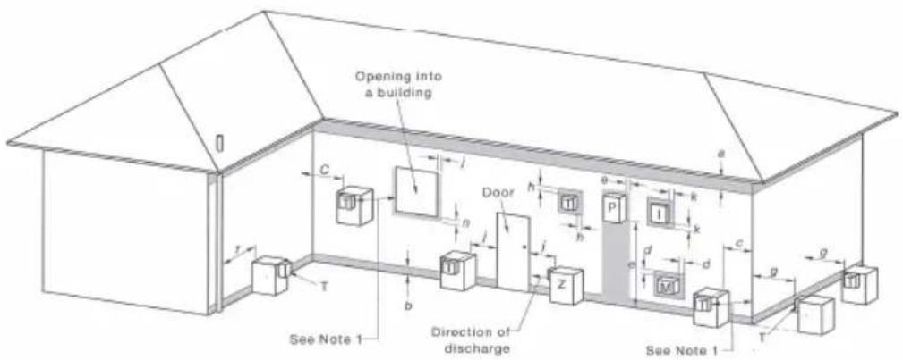
I = Mechanical air inlet M = Gas meter P = Electricity meter or fuse box T = Flue terminal Z = Fan-assisted appliance only
Shading indicates prohibited area for flue terminals
| Ref. | Item | Minimum clearances (mm) | |
| Natural draft | Auxiliary fan | ||
| A | Below eaves, balconies and other projections | ||
| • Appliances up to 50 MJ/h input | 300 | 200 | |
| • Appliances over 50 MJ/h input | 500 | 300 | |
| B | From the ground, above a balcony or the other surface | 300 | 300 |
| C | From a return wall or external corner | 500 | 300 |
| D | From a gas meter (M) (vent terminal location of regulator) | 1000 | 1000 |
| E | From an electricity meter or fuse box (P) | 500 | 500 |
| F | From a drain or soil pipe | 150 | 75 |
| G | Horizontally from any building structure or obstruction facing a terminal | 500 | 500 |
| H | From any other flue terminal, cowl or combustion air intake | 500 | 300 |
| J | Horizontally from an openable window, door non-mechanical air inlet, or any other opening into a building with the exception of sub-floor ventilation | ||
| • Appliances up to 150 MJ/h input | 500 | 300 | |
| • Appliances between 150 and 200 MJ/h input | 1500 | 300 | |
| • Appliances over 200 MJ/h input | 1500 | 1500 | |
| • All fan-assisted flue appliances, in the direction of discharge | 1500 | ||
| K | From a mechanical air inlet, including spa blower | 1500 | 1000 |
| N | Vertically below an openable window, non-mechanical air inlet, or any other opening into a building with the exception of sub-floor ventilation | ||
| • Space heaters up to 50 MJ/h input | 150 | 150 | |
| • Other appliances up to 50 MJ/h input | 500 | 500 | |
| • Appliances between 50 and 150 MJ/h input | 1000 | 1000 | |
| • Appliances over 150 MJ/h input | 1500 | 1500 | |
*Unless appliance is certified for closer installation

NOTE
- All distances are measured to the nearest part of the terminal.
• See Appendix J, Figures J2(a) and J3(a), for clearances required from a flue terminal to an LP Gas cylinder. A flue terminal is considered to be a source of ignition. - For appliances not addressed above acceptance should be obtained from the technical regulator.
4.4 GAS CONNECTION
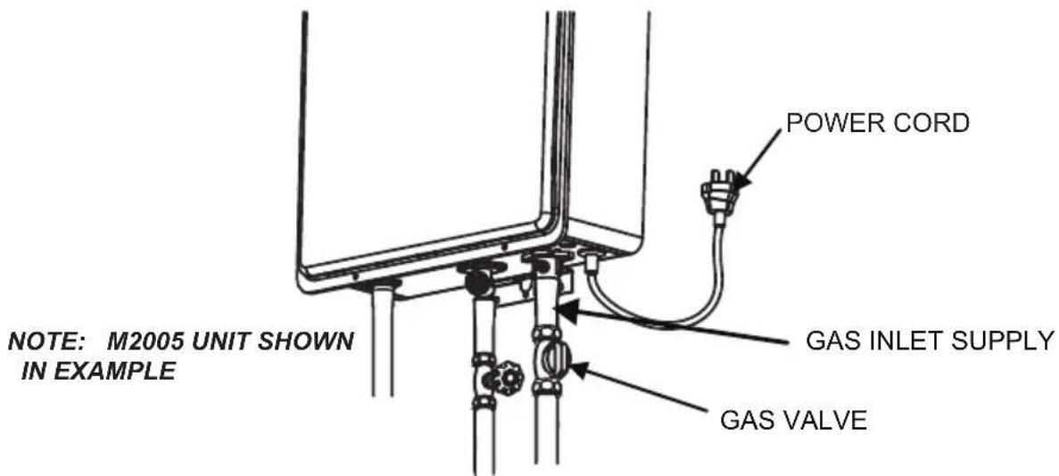
CAUTION
- Turn off the electric power to the water heater and manual gas valve located on the outside of the unit before beginning gas connection.
- Confirm the position of the gas inlet. Do not connect water line to gas inlet.
4.5 SIZING AND CONNECTION SUITABILITY
- Check the gas type label to make sure that the unit was built for the type of gas you will be using, and that the gas inlet pressure is within the appropriate range. (Please refer to p.4.)
- Gas pressure below this specified range for the water heater and/or insufficient gas volume will adversely affect performance.
- Inlet gas pressure must not exceed the maximum values; gas pressure above the specified range will cause dangerous operating conditions and damage to the unit.
- Until testing of the main gas line supply pressure is completed, ensure the gas line to the water heater is disconnected to avoid any damage to the water heater.
- Size the gas piping according to AS/NZS5601 installation code for the correct pipe sizing for the water heater.
- Always use approved connectors to connect the unit to the gas line. Always purge the gas line of any debris before connecting to the water heater.
• Install a manual gas shut-off valve between the water heater and the gas supply line. - The regulator is preset at the factory. It is computer controlled and is not to be adjusted by any person other than a licensed professional.
- When the gas connections are completed, perform a gas leak test either by applying soapy water to all gas fittings and observing for bubbles or by using a gas leak detection device.

WARNING
Conversion of this unit from natural gas to propane (ULPG) or propane (ULPG) to natural gas cannot be done in the field. Contact your supplier to get the correct unit for your gas type.
4.6 MEASURING INLET GAS PRESSURE AND TESTING GAS LEAKAGE
The appliance and its gas connections must be fully tested before the unit is put into operation for proper performance and safety.
NOTE: M2005 UNIT SHOWN IN EXAMPLE
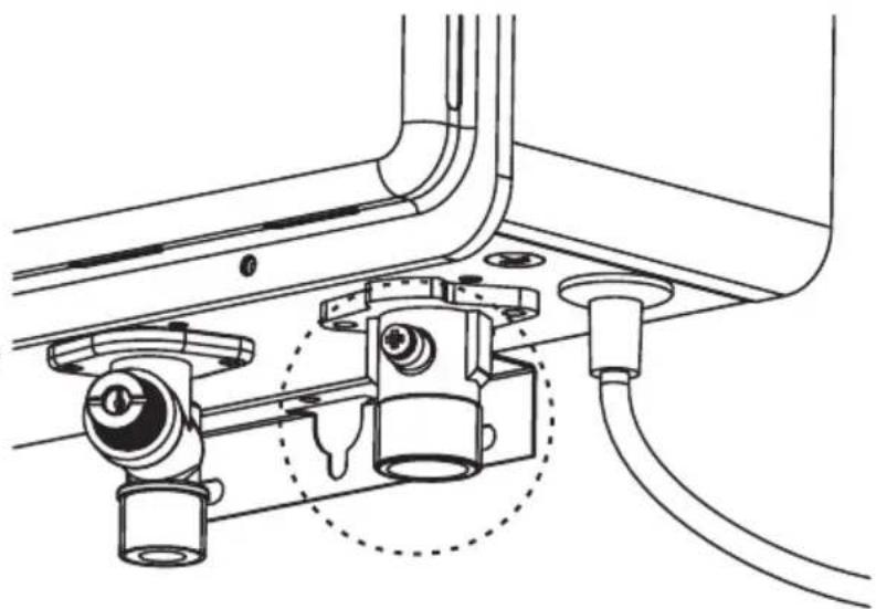
natural_image
Technical line drawing of a mechanical assembly with no visible text or symbols- Shut off the manual gas valve on the supply gas line.
- Open a tap/outlet. The unit should turn on and the gas in the gas pipe line should be purged. Leave the tap/outlet running until the unit shuts down due to lack of gas supply. Then turn off the tap/outlet.
- Remove the screw on the pressure port located on the gas inlet of the water heater shown in the diagram to the above.
- Connect the manometer to the pressure port.
- Re-open the manual gas valve. Check to see that there are no gas leaks.
- Open some of the fixtures that use a high flow rate to turn on the water heater.
- Check the inlet gas pressure. When the water heater is at a maximum operation capacity, the inlet gas pressure point must be within the appropriate range. (Please refer to p.4)
4.7 WATER CONNECTIONS
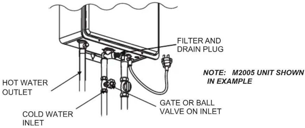
- All pipes, pipe fittings, valves and other components, including soldering materials, must be suitable for potable water systems.
- A manual shut off valve must be installed on the cold water inlet to the water heater between the main water supply line and the water heater.
- Only a gate valve or a ball valve is to be used on the cold water supply.
- Check the cold water pressure. If above 1000 kPa an approved limiting valve must be fitted.
- Before installing the water heater, flush the water line to remove all debris, and after installation is complete, purge the air from the line. Failure to do so may cause damage to the heater.
- There is a wire mesh filter to discourage debris from entering your heater. Clean filter after initial installation to ensure no debris from the pipe work has clogged it.

WARNING
Do not reverse the hot outlet and cold supply line connections to the water heater as this will cause your heater to operate improperly.
4.8 ELECTRICAL CONNECTION
- The water heater must be electrically grounded. Do not attach the ground wire to either the gas or water piping.
- The water heater requires an AC 240V 50Hz electrical power supply and draws a current of 0.8A. The weather-proof power point should be no more than 1 meter from the base of the water heater for easy access.
• Install a power switch so that the electrical power can be switched off if necessary. - If the cord supplied with this appliance must be replaced, it must be replaced with the correct appliance wiring material supplied by the Manufacturer.
- When servicing or replacing parts within the water heater, label all wires prior to disconnection to facilitate an easy and error free reconnection. Verify proper operation after servicing
5. REMOTE CONTROLLER (OPTIONAL)
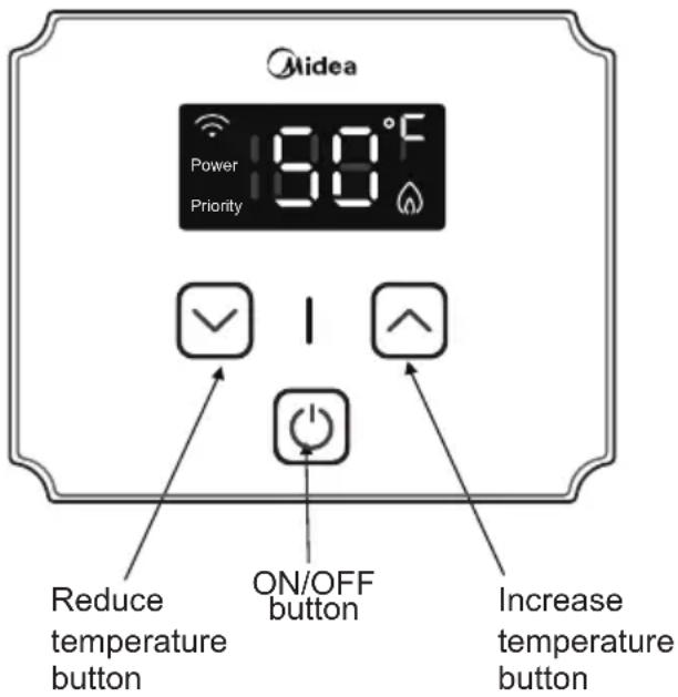
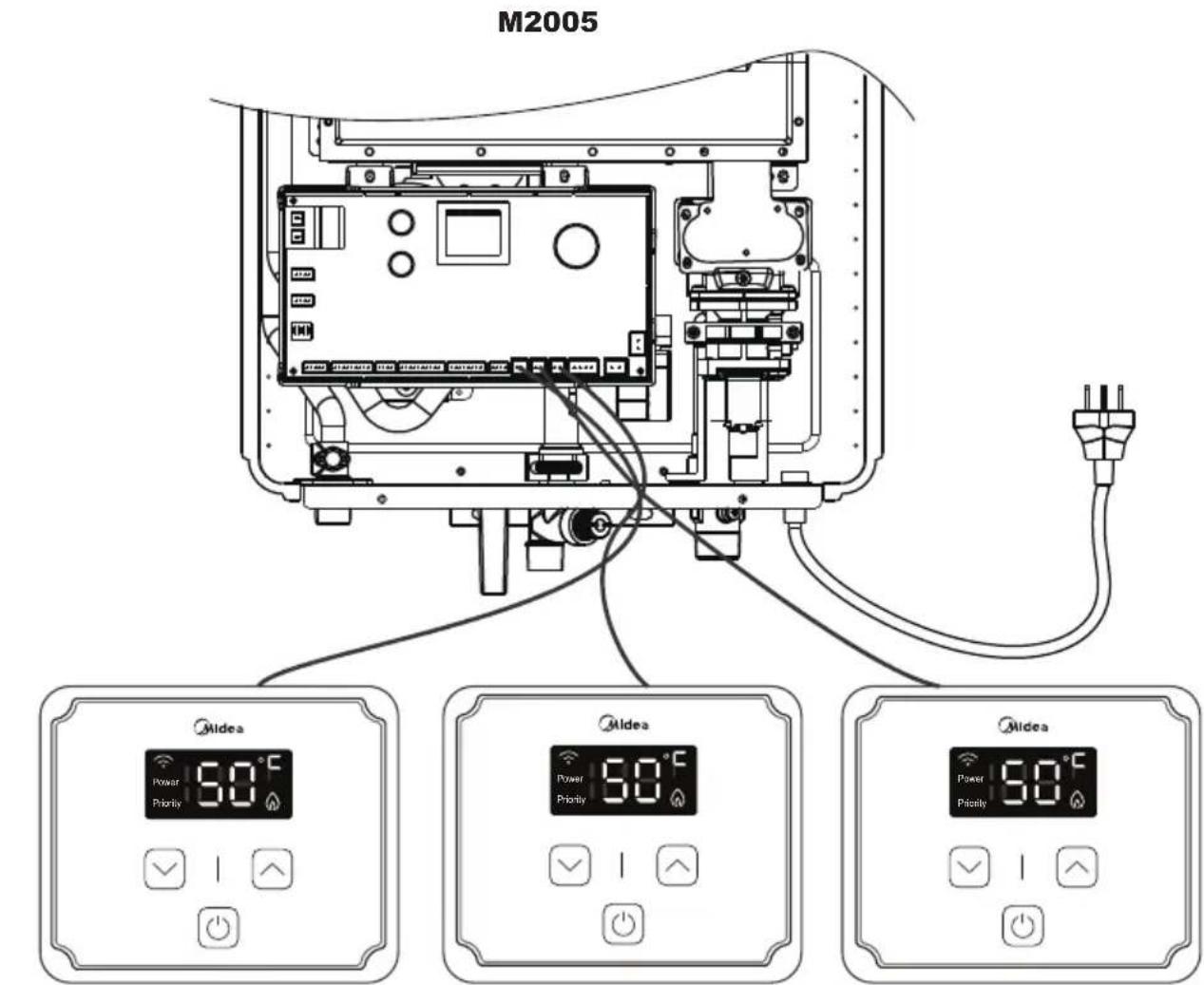
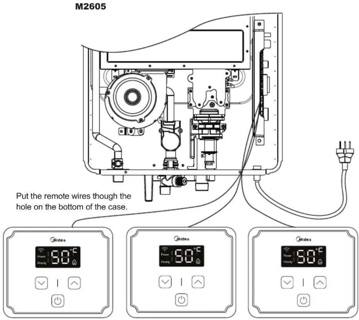
Remote controllers are available as an optional extra. The water heater can be installed with up to three remote controllers. Each remote controller has two functions which can adjust the set temperature and indicate the error code.
- PRIORITY function: The controller that is activated first (i.e. button is pressed) is given PRIORITY function, and can freely adjust the temperature. Remaining controllers will display the set temperature however will not be able to make any adjustments. After a 10 minute period of inactivity the priority on the first remote will cease and priority can then be assigned to another remote by activating it (i.e. a button is pressed). Then the new controller has priority and the cycle repeats
- Default setting temperature: At the initial power on, the setting temperature will be the same as the value set on DIP switch. After the initial use, it will remember the former setting temperature.
- All water heater models have self diagnostic function for safety and convenience when trouble shooting. If there is a problem with the installation or the unit, it will display a numerical error code on the remote controller (or the LED of the computer board will be blink.)
Remote controller installation requirements
- The remote controllers are splash resistant, however should not be positioned where it can be splashed directly & should be appropriately sealed between the surface of the wall & controller.
- The remote controller can be installed in the bathroom provided it is correctly installed.
Remote controllers output temperature setting (70°C mode)
- The remote controller is able to adjust the output temperature in the range of 38^ C to 65^ C in one degree increments.
Remote controllers output temperature setting (50°C mode)
- The remote controller is able to adjust the output temperature in the range of 38^ C to 48^ C in one degree increments.
5.1 REMOTE CONTROLLER INSTALLATION
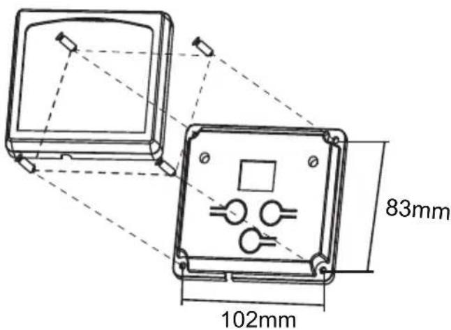
- The remote controller shall be connected by a cable with the specifications below:
a. Minimum 18AWG wire
b. Maximum run of 60m
- Attach the remote control to the wall with screws supplied.

WARNING
- DO NOT locate the remote controls where they may come into contact with water.
• DO NOT position the remote controls in the vicinity of chemicals.
• DO NOT position the remote controls over a heat generating appliance (i.e. cooker, toaster) - DO NOT position the remote controls where materials may spill onto them.
- PLEASE NOTE IF THE CONTROLS ARE TO BE FITTED TO A METAL SURFACE AN INSULATION PLATE SHOULD BE PROVIDED BEHIND THE MOUNTING POSITION.
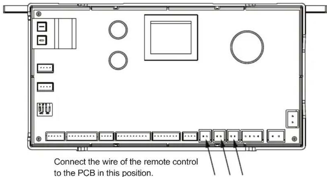
5.2 CONNECTION OF REMOTE CONTROLLER WIRING TO THE WATER HEATER
- Turn off the power supply to the water heater.
- Remove the front cover from the water heater. There are 4 screws on the front cover.
- Feed the remote wires through the hole on the bottom of the case.
- Connect the first controller only and turn on the power supply to the water heater.
- Turn off the first controller by pressing the on/off button (LED light will turn off).
- Continue to connect any additional remote control wires to the remote terminals directly.
DO NOT jump or short-circuit wires otherwise the PCB may become damaged.
- Return the front cover.
DO NOT turn on the remotes until instructed.
-
Activate the first remote by pressing & holding the 'cool' (down arrow) button for 5 secs until a single beep sounds. Then press & hold the 'heat' (up arrow) button for 5 seconds until the LED screen lights up.
-
Adjust the on screen value to set the ID (available ID's include 00, 01, 02). Press the on/off button to confirm
-
Repeat for all additional controllers.
-
Controllers can now be turned on and will operate as per the PRIORITY function (refer to p. 15)
- Check the GAS and WATER CONNECTIONS for leaks before startup for the first time.
- Open the main gas supply valve to the unit using only your hand to avoid any spark. Never use tools. If the knob will not turn by hand, do not try to force it. Forced repair may result in a fire or explosion due to gas leaks.
- Check the GAS PRESSURE. Refer to p.4
- Do not try to light the burner manually. It is equipped with an electronic ignition device which automatically lights the burner.
- Check for PROPER VENTING and COMBUSTIBLE AIR to the heater.
- Purge the GAS and WATER LINES to remove any air pockets.
- Do not use this water heater if any part has been submersed under water.
1. Once the above checks have been completed, please clean filter of any debris. Refer to p. 20 for instructions. | 2. Fully open the manual water control valve on the water supply line[IMAGE] | 3. Open a hot water tap to verify that water is flowing to that tap.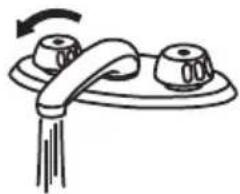 |
4. Fully open the manual gas control valve installed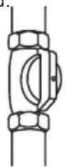 | 5. Turn on the 240 volt 50 Hz power supply to the water heater.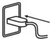 | 6. Now you are ready to enjoy hours of endless hot water.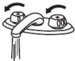 |
7. NORMAL OPERATION
- Flow rate to activate the water heater: ≥ 2.2 litre per minute.
- Flow rate to keep the water heater running: ≤1.8 litre per minute.
7.1 NORMAL OPERATION WITHOUT REMOTE CONTROLLER
1. Open a hot water tap. 2.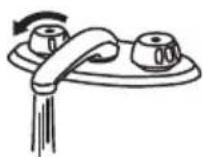 | Mix cold water with the hot to get the correct temperature water.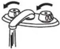 | 3. Close the hot water tap.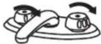 |
7.2 NORMAL OPERATION WITH MULTIPLE REMOTE CONTROLLERS INSTALLED
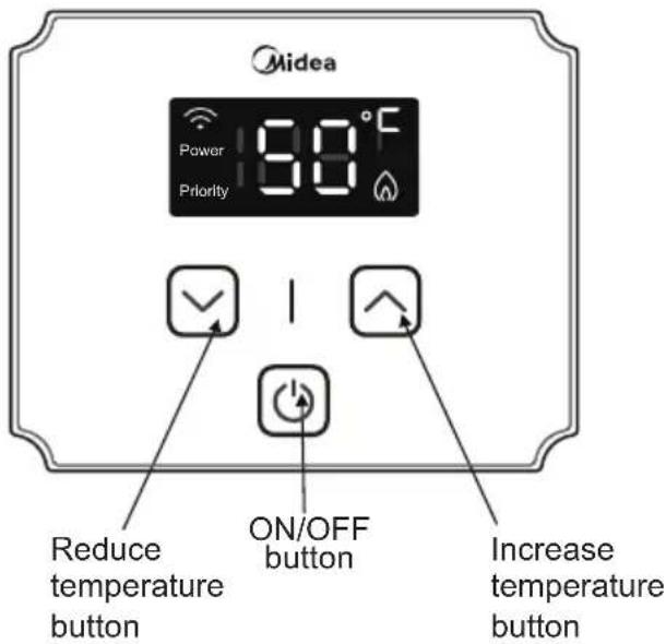
- Press the ON/OFF button. The Power light will become lit on the remote controller with setting temperature displayed on each of the remote controllers. The controller with PRIORITY function will have a flashing Power light.
- Set the required temperature using the Cool & Heat Buttons. (The temperature setting can only be changed by the priority controller. (Refer to p. 15 for detail regarding the PRIORITY function)
- Open a hot water tap, and ensure the Burner ON light is lit. Mix cold water with the hot as required.
- Close the hot water tap. The Burner light will turn off.
7.3 FREEZE PREVENTION
CAUTION
Only the pipes and heat exchanger inside the water heater will be protected. Any hot or cold water pipes located outside of the unit will not be protected. Proper protection and insulation of these pipes will be required to ensure these are protected from freezing.
8. MAINTENANCE AND SERVICE
The water heater should be checked at least once a year or as necessary by a licensed technician. If repairs are needed, any repairs should be done by a licensed technician. The water heater's lifetime may be extended by regular maintenance.

WARNING
Turn off the electrical power supply and close the manual gas control valve and the manual water control valve before servicing.
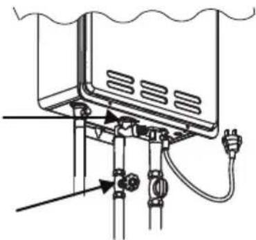
- Clean the cold-water inlet filter. (Refer to diagram below).
- Be sure that all openings for combustion air are not blocked. If blocked, remove obstruction.
- Check that the opening for exhaust is not blocked. If blocked, shutoff the water heater's combustion. And then after a while, remove obstruction. DO NOT touch while unit operating, otherwise you might get burnt due to high temperature.
- Check the gas pressure.
- Keep the area around the water heater clear. Remove any combustible materials, gasoline or any flammable vapors and liquids.
8.1 UNIT DRAINING AND FILTER CLEANING
- Close the manual gas shut off valve.
- Turn off the power supply to the water heater.
- Close the manual water shut off valve.
- Open all hot water taps in the house (Bathroom, kitchen, laundry, etc.). When the residual water flow has ceased, close all hot water taps.
- Have a bucket or container to catch the water from the unit's drain plugs. Unscrew the drain plugs to drain all the water out of the unit.
- Wait a few minutes to ensure all water has completely drained from unit.
- Clean the filter: Check the water filter located within the cold inlet. With a tiny brush, clean the water filter of any debris which may have accumulated and reinsert the filter back into the cold water inlet.
- Securely screw the drain plugs back into place. Hand- tighten only.
REMOVE BY TURNING COUNTER CLOCKWISE AND THEN CLEAN AND REPLACE
- TURN OFF THE WATER INLET SUPPLY VALVE.
- OPEN A HOT WATER TAP TO RELEASE THE LINE PRESSURE.
natural_image
Technical diagram of a water heater system with pipes and connections (no text or labels)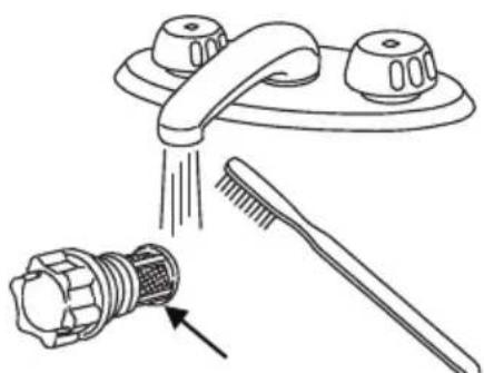
natural_image
Line drawing of a kitchen sink with a showerhead and a toothbrush, showing no text or symbols.FILTER
8.2 GENERAL TROUBLESHOOTING
| ~ TEMPERATURE and AMOUNT OF HOT WATER ~ | |
| PROBLEM POSSIBLE SOLUTIONS | |
| It takes long time to get hot water at the fixtures. | The time it takes to deliver hot water from the water heater to your fixtures depends on the length of piping between the two. The longer the distance or the larger the pipes, the longer it will take to get hot water. |
| The water is not hot enough. | Compare the flow and temperature. See the chart on p. 24.Check cross plumbing between cold water lines and hot water lines.Is the gas supply valve fully open? (p. 18)Is the gas line sized properly? (p. 12)Is the gas supply pressure enough? (p. 13)Is the set temperature set too low? (p. 23) |
| The water is too hot. | Is the set temperature set too high? (p. 23) |
| The hot water is not available when a fixture is opened. | Make sure the unit has 240V 50Hz power supply.If you are using the remote controller, is the power button turned on? (p. 19)Is the gas supply valve fully open? (p. 18)Is the water supply valve fully open? (p. 18)Is the filter on cold water inlet clean? (p. 20)Is the hot water fixture sufficiently open to draw at least 3.0l/min through the water heater? (p. 19)Is the unit frozen?Is there enough LPG in the bottle? (for propane) |
| The hot water gets cold and stays cold. | Is the flow rate enough to keep the water heater running? (p. 19)Is the gas supply valve fully open? (p. 18)Is the filter on cold water inlet clean? (p. 20)Are the fixtures clean of debris and obstructions? |
| Fluctuation in hot water temperature. | Is the filter on cold water inlet clean? (p. 22)Is the gas line sized properly? (p. 12)Is the supply gas pressure enough? (p. 13)Check for cross connection between cold water lines and hot water lines. |
| ~ WATER HEATER ~ | |
| PROBLEM POSSIBLE SOLUTIONS | |
| The Unit does not ignite when water goes through the unit. | Is the flow rate over 3.0l/min? (p. 19)Check for the filter on cold water inlet. (p. 20)Check for reverse connection and cross connection.If you use the remote controller, is the power button turned on? (p. 19) |
| The fan motor is still spinning after operation has stopped. | This is normal. After operation has stopped, the fan motor keeps running for 15 ~ 75 seconds in order to re-ignite quickly, as well as push all exhaust gas out of the flue. |
| ~ REMOTE CONTROLLER (OPTIONAL) ~ | |
| PROBLEM POSSIBLE SOLUTIONS | |
| Remote controller does not display anything when the power button is turned on. | Press the ON/OFF button.If the light does not light up ⇒Make sure the unit has power supply.Make sure the connection to the unit is correct.(p. 17) |
| An ERROR code is displayed. Please | see the p.22 |
| Remote controller can not change the set temperature. | Is power light flashing?If it is not, locate priority controller and turn off, or wait for 10 mins on inactivity |
8.3 PCB ERROR CODES
The water heater is self diagnostic for safety and convenience when troubleshooting. If there is a problem with the installation or the unit, it will display an error code on the remote controller. Consult the following chart for each error code.
When remote controller is installed
Error Codes On the Remote controllers
| Error code | Fault name Fault | definition description Fault reset method | |
| E0 Outlet temperature sensor failure | When the system is started or working normally, if the system detects an open or short circuit of the outlet temperature sensor, it is determined that the outlet temperature sensor is faulty | Turn off water flow or shut down to eliminate | |
| F2 Inlet water temperature sensor failure | When the system starts or works normally, if the system detects that the inlet water temperature sensor is open or short-circuited, it is determined that the inlet water temperature sensor is faulty | Turn off water flow or shut down to eliminate | |
| E1 Unexpected flameout failure | When the system is in a burning state, when an unexpected flameout is detected, the valve is closed within 1 second, then cleaned for 1 second, and then the ignition valve is re-ignited (the water flow has not been closed). If the system ceases to fire unexpectedly again, close the valve within 1 second, then clean it for 1 second, and then re-ignite the suction valve to work (the water flow has not been closed).If the system detects an accidental flameout for the third time in a cycle with water flow during startup, it is judged as an accidental flameout failure | Turn off water flow or shut down to eliminate | |
| C0 Ignition failure When the system needs to be ignited, it can be fired up to 8 seconds at a time and 5 times at most. Before the second, third, fifth, ignition, the fan needs to be cleaned for 3 seconds, and before the fourth and seventh ignition, the fan needs to be cleaned for 8 seconds.If there is no successful fire 5 times in a row, it is judged as ignition failure | system needs to be ignited, it can be fired up to 8 seconds at a time and 5 times at most. Before the second, third, fifth, ignition, the fan needs to be cleaned for 3 seconds, and before the fourth and seventh ignition, the fan needs to be cleaned for 8 seconds. | Turn off water flow or shut down to eliminate | |
| E2 False flame signal failure | Before starting the ignition work, the system has detected the flame signal and judged it as a false fire fault | Turn off water flow or shut down to eliminate | |
| C1 Residual fire failure | When the system is turned on, a flame signal is detected for 2 seconds from “after closing the valve to stop burning for 3 seconds” to “before the end of post-sweeping”, and it is judged as a residual fire fault | After the shutdown is eliminated or the water flow is shut off for 1 second, no flame can be detected and can be eliminated. | |
| E3 Thermostat (overheating) failure | When the system starts or works normally, it is detected that the overheating protection thermostat is disconnected, and the thermostat is judged to be faulty | Turn off water flow or shut down to eliminate |
| E4 Outlet temperature over temperature fault | When the system is in a burning state, if the outlet temperature is detected to exceed 85°C for 3 consecutive seconds, it is determined that the outlet temperature is over temperature. | Turn off water flow or shut down to eliminate |
| C4 Air duct blockage failure | When the system is in the burning state, when the smoke pipe is blocked or the back flow air is to a certain degree (the action value is determined by the current fan speed and current), it is judged as a wind blockage fault. | Turn off water flow or shut down to eliminate |
| E5 Fan failure When the system is turned on and there is water, the wind speed is less than 600r/min for 2 seconds after the fan is started, and it is judged as a fan failure | Turn off water flow or shut down to eliminate | |
| E6 Solenoid valve failure | When the system detects that the solenoid valve (including the proportional valve) drives the triode short circuit at startup, or the valve wiring of the whole machine is disconnected, it is determined that the solenoid valve is faulty | Turn off water flow or shut down to eliminate |
| E7 Remote control communication failure | The PCB of the remote control and the water heater cannot be connected, and there is no signal AC feedback | shut down to eliminate |
| EE Timeout fault The system | burns continuously for more than 40 minutes in a 40-minute timer mode, and it is judged as a timeout fault | Turn off water flow or shut down to eliminate |
Unable to recover fault code
| Error code | Fault name Fault definition description | |
| A0 Watchdog circuit failure | Controller watchdog circuit or chip is abnormal | |
| A1 MCU PC | command failure | The PC command of the main chip of the controller is abnormal |
| A2 Instruction | compilation and | Controller main chip instruction compilation and execution failure |
| A3 MCU RAM | fault | The main chip ram of the controller does not pass the walk pat check |
| A4 | MCU ROM fault | The CRC test of the main chip ROM of the controller failed |
| A5 | MCU Register fault | The controller master chip failed the register test |
When these codes appear, the system cannot be recovered at this time. You need to contact the after-sales personnel to replace the corresponding PCB
8.4 WIRING DIAGRAM
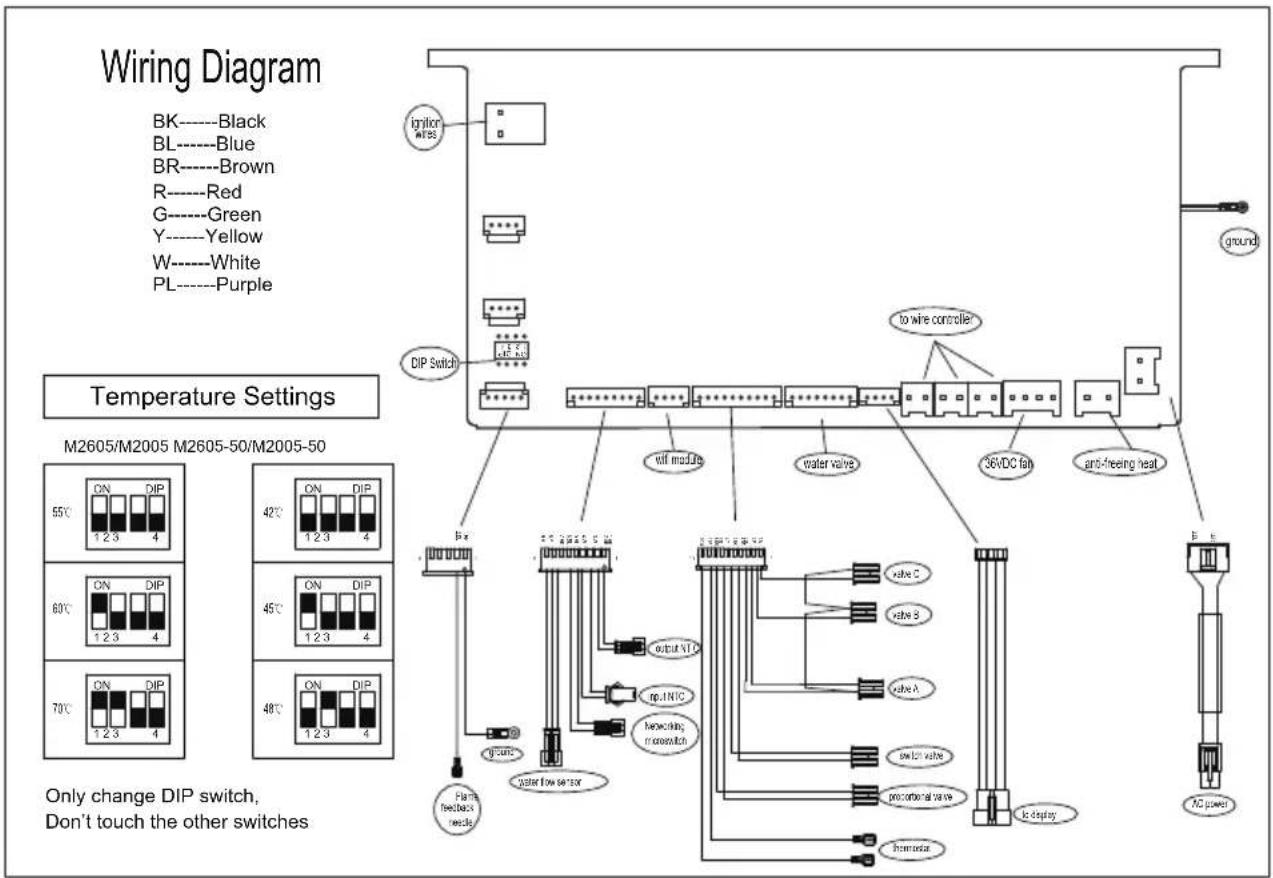
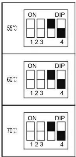
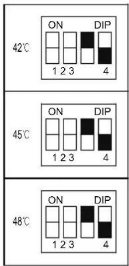
The DIP Temperature setting
M2605/M2005 M2605-50/M2005-50
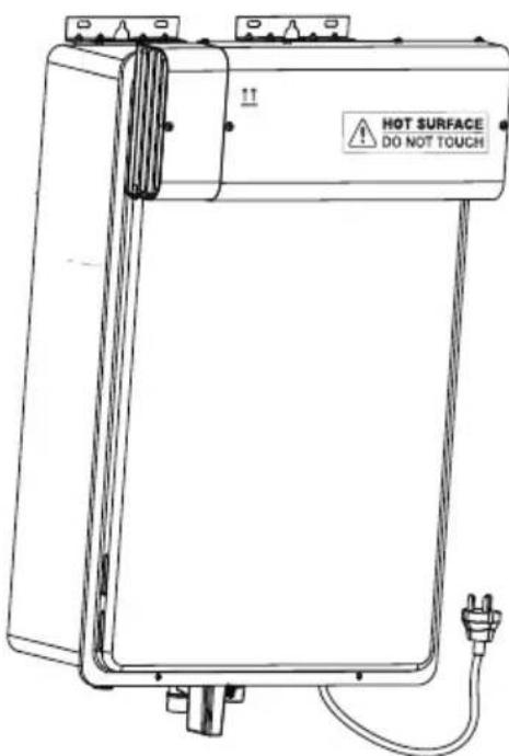
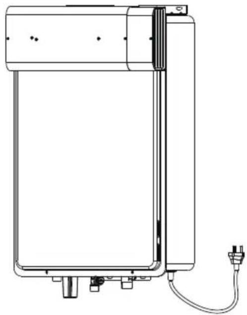
- If you choose to include a side diverter, it must be installed by a professional
- Do not touch the flue diverter during operation as the surface will be extremely hot
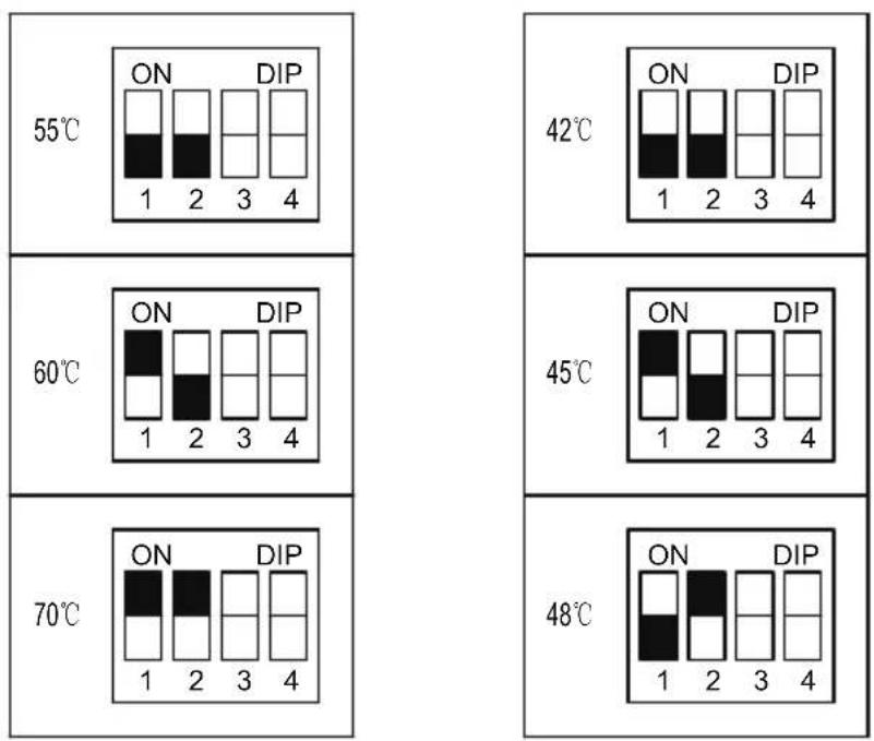
To ensure normal operation of the product when a side diverter is installed please configure the switches according to the below diagram.
M2605/M2005 M2605-50/M2005-50
Make sure that the drain holes is facing down during installation
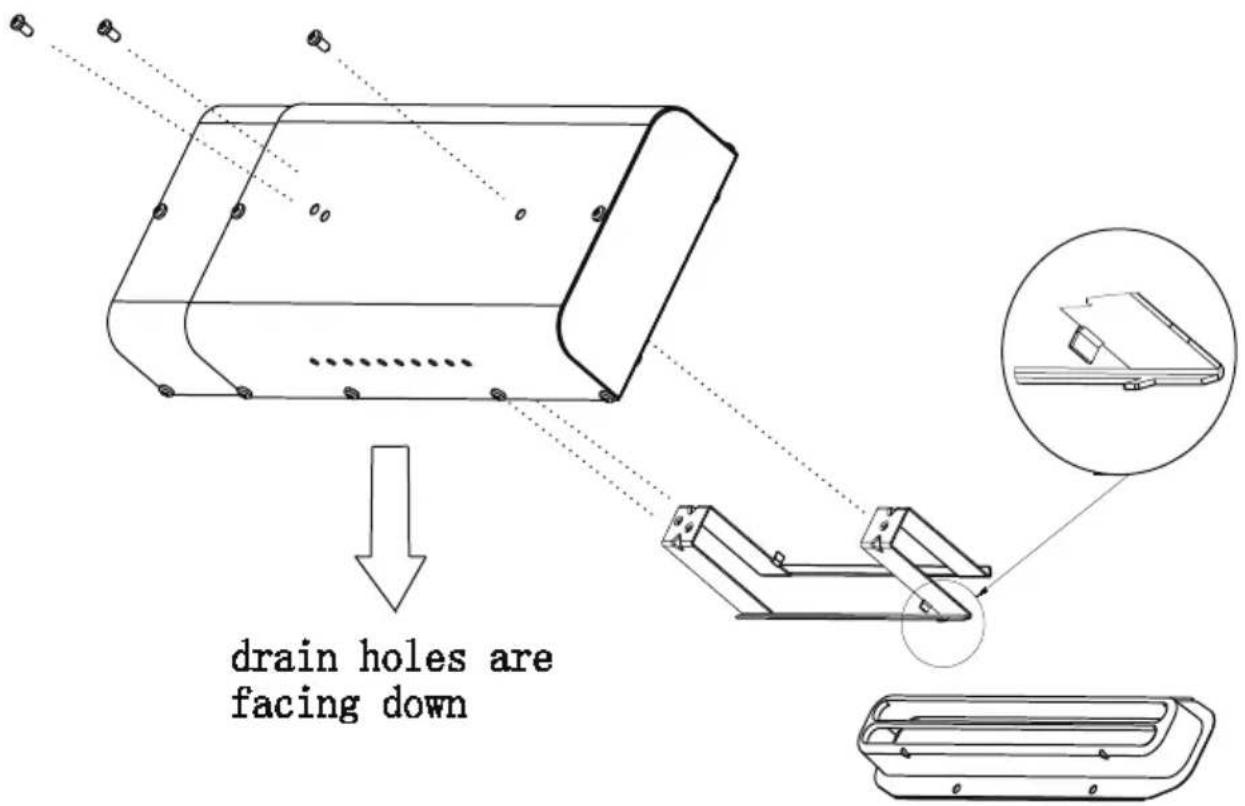
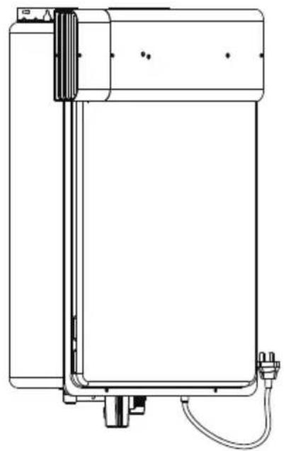
Only authorised personnel can install a side diverter. The side diverter incorporates the following mechanical means to prevent incorrect installation, please pay attention:
- Two screws are installed on the left side of the mounting bracket, and one screw is installed on theright side, as per image above. Note the position of the left screws are not in a horizontal line.
- The mounting bracket for the side diverter has a locating tab on the lower right, as per image above, to ensure only this side is fitted to the right side exhaust opening.
Left side of flue gas outlet
natural_image
Technical line drawing of a vertical cylindrical device with attached components and wiring (no text or symbols)Right side of flue gas outlet
natural_image
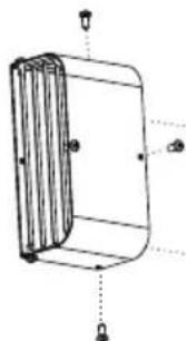
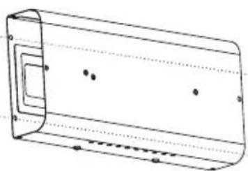
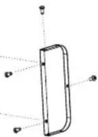
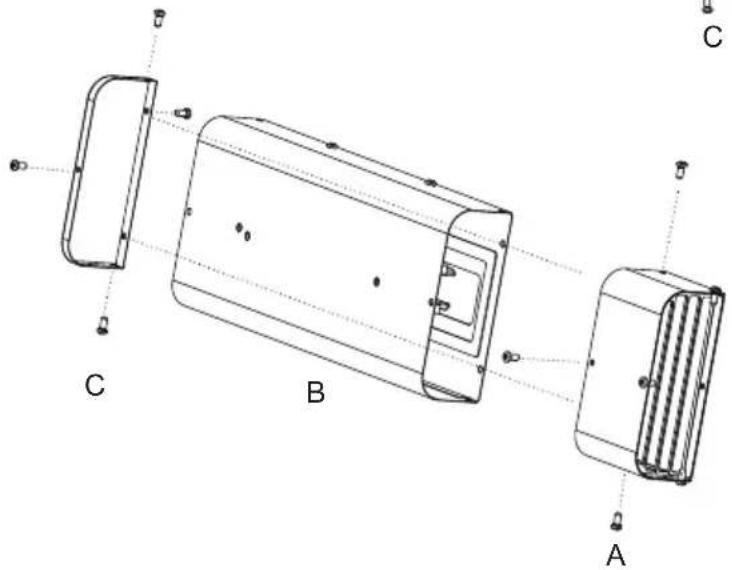
Technical line drawing of a rectangular electronic device with mounting feet and wiring (no text or symbols)The side diverter can be configured to have the flue gas outlet on either the left or the right side. To reverse the direction complete the following (as shown in the figure below):
- Remove the fixed screw
- Swap the A & C module positions
- Refix the corresponding screws
natural_image
Technical line drawing of a cylindrical device with internal vertical structure and mounting points (no text or symbols)A
natural_image
Technical line drawing of a rectangular enclosure with internal components and dot markers (no text or symbols)B
natural_image
Simple line drawing of a rectangular object with four corner points and dotted lines indicating alignment (no text or symbols)Left side of flue gas outlet
Right side of flue gas outlet
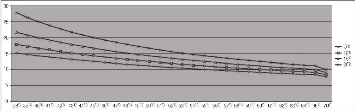
8.6 WATER FLOW AND WATER TEMPERATURE (M20)
line
| Temperature | 5°C | 10°C | 15°C | 20°C | | ----------- | ----- | ----- | ----- | ----- | | 38°C | 28.0 | 22.0 | 18.0 | 15.0 | | 39°C | 26.0 | 21.0 | 17.0 | 14.5 | | 40°C | 24.0 | 20.0 | 16.5 | 14.0 | | 41°C | 22.0 | 19.0 | 16.0 | 13.5 | | 42°C | 20.0 | 18.0 | 15.5 | 13.0 | | 43°C | 18.0 | 17.0 | 15.0 | 12.5 | | 44°C | 16.0 | 16.0 | 14.5 | 12.0 | | 45°C | 14.0 | 15.0 | 14.0 | 11.5 | | 46°C | 12.0 | 14.0 | 13.5 | 11.0 | | 47°C | 10.0 | 13.0 | 13.0 | 10.5 | | 48°C | 8.0 | 12.0 | 12.5 | 10.0 | | 49°C | 6.0 | 11.0 | 12.0 | 9.5 | | 50°C | 4.0 | 10.0 | 11.5 | 9.0 | | 51°C | 2.0 | 9.0 | 11.0 | 8.5 | | 52°C | - | - | - | - | | 53°C | - | - | - | - | | 54°C | - | - | - | - | | 55°C | - | - | - | - | | 56°C | - | - | - | - | | 57°C | - | - | - | - | | 58°C | - | - | - | - | | 59°C | - | - | - | - | | 60°C | - | - | - | - | | 61°C | - | - | - | - | | 62°C | - | - | - | - | | 63°C | - | - | - | - | | 64°C | - | - | - | - | | 65°C | - | - | - | - | | 70°C | - | - | - | - |- The flow rate through the water heater is limited to a maximum of 20L/min.
- The temperature setting, along with the supply temperature of the water will determine the flow rate output of the unit.
- Please refer to the temperature versus litre per minute chart to determine the likely flow rates based on your local ground water temperature and your desired outlet water temperature combination.
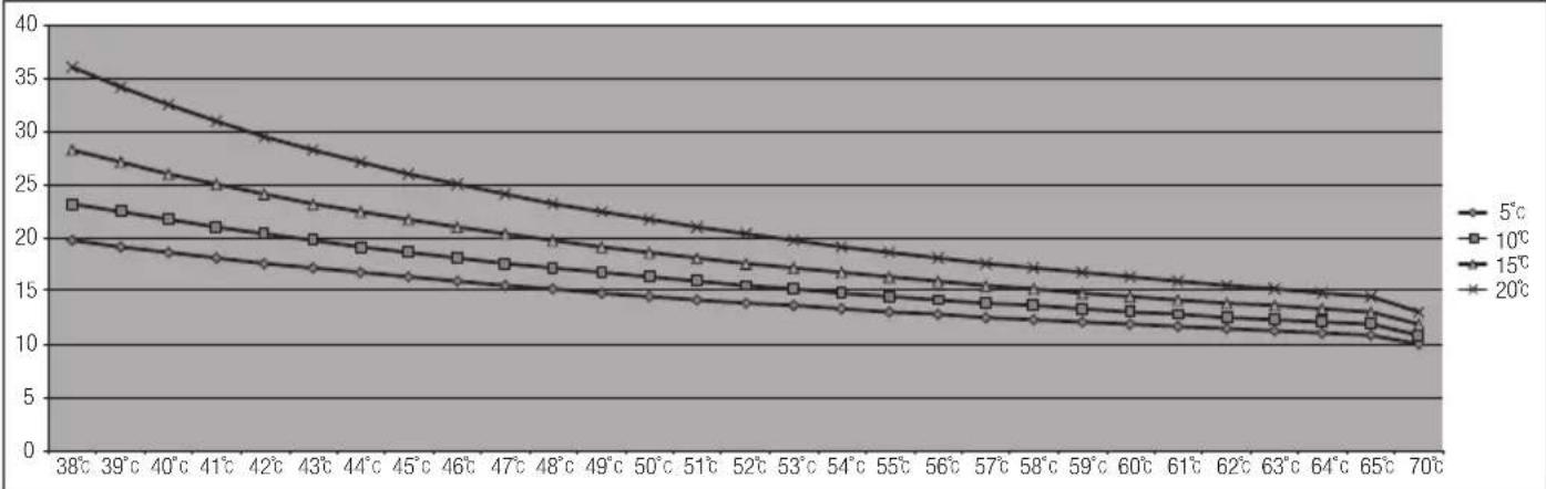
8.7 WATER FLOW AND WATER TEMPERATURE (M2605)
line
| Latitude | 5°C | 10°C | 15°C | 20°C | | -------- | ---- | ---- | ---- | ---- | | 38°C | 36 | 28 | 23 | 20 | | 39°C | 35 | 27 | 22 | 19 | | 40°C | 34 | 26 | 21 | 18 | | 41°C | 33 | 25 | 20 | 17 | | 42°C | 32 | 24 | 19 | 16 | | 43°C | 31 | 23 | 18 | 15 | | 44°C | 30 | 22 | 17 | 14 | | 45°C | 29 | 21 | 16 | 13 | | 46°C | 28 | 20 | 15 | 12 | | 47°C | 27 | 19 | 14 | 11 | | 48°C | 26 | 18 | 13 | 10 | | 49°C | 25 | 17 | 12 | 9 | | 50°C | 24 | 16 | 11 | 8 | | 51°C | 23 | 15 | 10 | 7 | | 52°C | 22 | 14 | 9 | 6 | | 53°C | 21 | 13 | 8 | 5 | | 54°C | 20 | 12 | 7 | 4 | | 55°C | 19 | 11 | 6 | 3 | | 56°C | 18 | 10 | 5 | 2 | | 57°C | 17 | 9 | 4 | 1 | | 58°C | 16 | 8 | 3 | 0.5 | | 59°C | 15 | 7 | 2 | 0.3 | | 60°C | 14 | 6 | 1 | 0.2 | | 61°C | 13 | 5 | 0.5 | 0.15 | | 62°C | 12 | 4 | 0.3 | 0.1 | | 63°C | 11 | 3 | 0.2 | 0.05 | | 64°C | 10 | 2 | 0.15 | 0.03 | | 65°C | 9 | 1.5 | 0.1 | 0.02 | | 70°C | - | - | - | - |- The flow rate through the water heater is limited to a maximum of 26L/min.
- The temperature setting, along with the supply temperature of the water will determine the flow rate output of the unit.
- Please refer to the temperature versus litre per minute chart to determine the likely flow rates based on your local ground water temperature and your desired outlet water temperature combination.
9. WI-FI MODULE & M-SMART LIFE APP (OPTIONAL)

NOTE
Wi-Fi & Voice Control is available as an additional option.
M2005 M2605
Do not jump or short circuit wires, otherwise the PCB may become damaged
9.1 INSTALLATION OF WI-FI MODULE (WITHOUT REMOTE CONTROLLER)
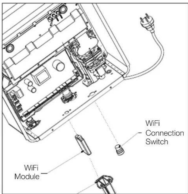
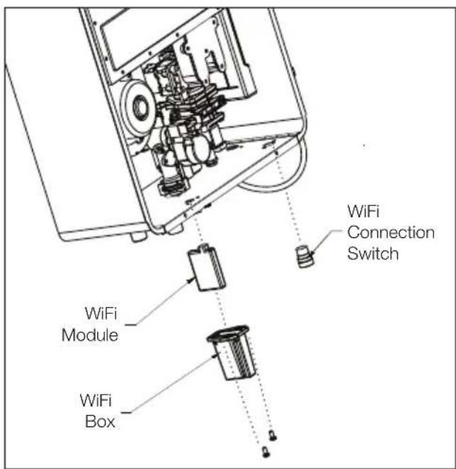
In order to use the M-Smart life app for systems without a remote controller, the WiFi module and the WiFi connection switch must be installed as follows:
- Turn off the power supply to the water heater.
- Remove the front cover from the water heater by removing the four cover screws.
- Remove the small cover plates at the connection points in the lower section of the main casing.
- Install the purchased accessories as shown in the agure on previous page:
- The WiFi module must be installed in the WiFi box and axed into position on the underside of the maincasing using screws.
- The WiFi connection switch can be simply screwed into position to the underside of the main unit.
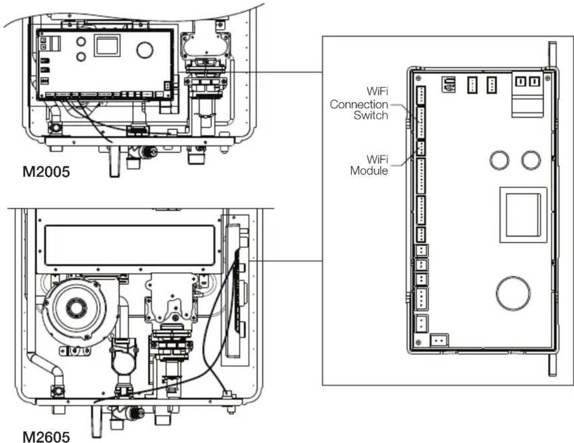
- Connect the accessories to the speciaed circuit connector on the PCB (refer previous page). The WiFi connection switch is the blue line.
- Replace the front cover and power up the unit by connecting the power plug.
- Connect to the WiFi network according to the app instruction (further information available on page 34).
9.2 INSTALLATION OF WI-FI MODULE (WITH REMOTE CONTROLLER)
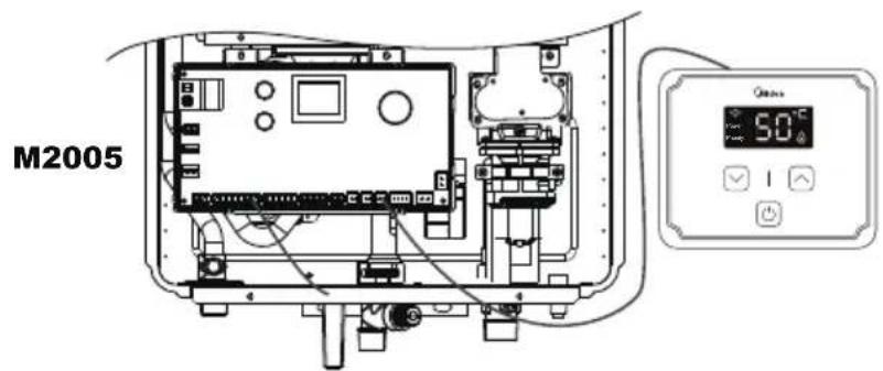
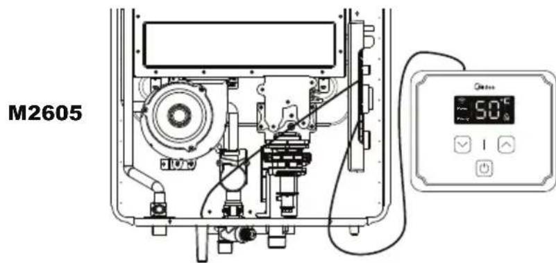
In order to use the M-Smart life app for systems that include a remote controller, only the addition of the WiFi module needs to be installed as the remote controller can detect the corresponding WiFi network functions. Instruction as follows:
- Turn off the power supply to the water heater.
- Remove the front cover from the water heater by removing the four cover screws.
- Remove the small cover plate at the connection point in the lower section of the main casing.
- Install the purchased accessory as shown in the \âgure\ on previous page:
- The WiFi module must be installed in the WiFi box and axed into position on the underside of the maincasing using screws.
- The remote controller must be installed as per the instruction in section 5.
- Connect the accessories to the specified circuit connector on the PCB (refer previous page).
- Replace the front cover and power up the unit by connecting the power plug.
- When the remote control displays '01', press and hold the "up" button for 3 seconds to trigger the network.(at this time, the buzzer will sound four times).
- Connect to the WiFi network according to the app guidelines (further information available on page 34).
REMOTE CONTROLLER WI-FI ICON & CONNECTION STATUS
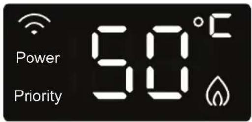
| WiFi icon on remote control WiFi connection status | |
| Flashing slowly WiFi icon(on for 1 second, off for 1 second)Will run for 10 mins, and go out if not connected | Waiting for connection(the device has turned on the hotspot or started the Bluetooth network broadcast) |
| Longer Flashing WiFi icon(on for 0.2 seconds, off for 0.2 seconds) | Equipment networking(APP networking during network operation) |
| Solidly lit WiFi icon Connection to network successful. | |
| Non lit WiFi icon | No corresponding serial number or WiFi module.Or unable to connect. |
9.3 USING YOUR APPLIANCE WITH THE M-SMART LIFE APP
Before you start, make sure that:
- Your smartphone is connected to home wifi network, and you know the network password.
- Make sure you are next to home appliances.
- The 2.4GHz (preferable) or 5GHz band wireless signal is enabled on your wireless router.
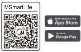
Download MSmartLife App
Scan the QR code below, or search for "MSmartLife" in Google play(Android devices) or App Store(ios devices) to download the app.
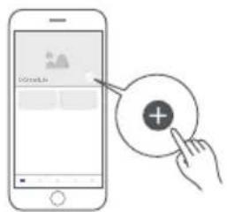
③ Add your appliance
Tap the "+"icon to add home appliance to your MsmartLife account.
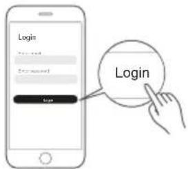
2 Register or Login account
Open the App and create a user account, if you already have one, just log in.
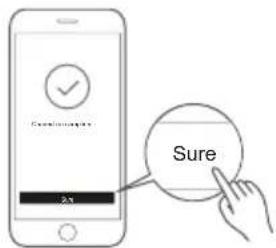
4 Connected to the network
Follow the instructions in the App to set up the WiFi connection. If the network connection fails, please refer to the App tips for operation.
WiFi Status Light
| Slowly flashing | Waiting for connection | |
| Quickly Flashing | Connecting | |
| Quickly flashing solid | Connected to your wireless router |
⚠️ Notes on networking
- When networking the product, please make sure that the mobile phone is as close as possible to the product.
- According to the App tips, if the product only supports 2.4GHz wifi communication, please note that the 2.4GHz network is selected for connection.
- Midea recommends WiFi router SSID names contain only alphanumeric values. If special characters, punctuation marks or spaces are used it might prevent the SSID name from showing up in the available networks to join in the App. Try it and if the SSID shows up then it is ok to use, otherwise log into the router and change the SSID name.
- A large number of devices on the WiFi router can affect network stability, there is no way that Midea can advise a specific number limitation as this depends on router quality and many other factors.
• If the router or WiFi name and WiFi password change, please repeat the above process to reconnect to the network. - As the product technology is updated, the content of MSmartLife may change, and the actual display in MSmartLifeApp shall prevail.
Product is subject to change without notice.
Please keep this manual for future reference
- Continuous Flow Gas Water Heater
- Installation And Operation Guide
- IMPORTANT NOTES ......2
- SPECIFICATION ....4
- INTRODUCTION 5
- INSTALLATION 9
- REMOTE CONTROLLER ....15
- M-SMART LIFE APP....31
- IMPORTANT NOTES
- INSTALLATION NOTES
- SERVICE NOTES
- WARNING
- PLUMBING NOTES
- WARNING —
- SPECIFICATIONS
- NOTES
- INTRODUCTION
- SAFETY GUIDELINES
- GENERAL GUIDELINES
- PROHIBITED
- INSTALLATION
- CONFIRM THE APPLIANCE SUITABILITY
- CAUTION
- SELECTING SUITABLE LOCATION FOR INSTALLATION
- CLEARANCES FOR OUTDOOR HEATER LOCATIONS-AS/NZS 5601.1:2013
- NOTE
- GAS CONNECTION
- SIZING AND CONNECTION SUITABILITY
- MEASURING INLET GAS PRESSURE AND TESTING GAS LEAKAGE
- WATER CONNECTIONS
- ELECTRICAL CONNECTION
- REMOTE CONTROLLER (OPTIONAL)
- Remote controller installation requirements
- Remote controllers output temperature setting (70°C mode)
- Remote controllers output temperature setting (50°C mode)
- REMOTE CONTROLLER INSTALLATION
- CONNECTION OF REMOTE CONTROLLER WIRING TO THE WATER HEATER
- NORMAL OPERATION
- NORMAL OPERATION WITHOUT REMOTE CONTROLLER
- NORMAL OPERATION WITH MULTIPLE REMOTE CONTROLLERS INSTALLED
- FREEZE PREVENTION
- MAINTENANCE AND SERVICE
- UNIT DRAINING AND FILTER CLEANING
- GENERAL TROUBLESHOOTING
- PCB ERROR CODES
- WIRING DIAGRAM
- WATER FLOW AND WATER TEMPERATURE (M20)
- WATER FLOW AND WATER TEMPERATURE (M2605)
- WI-FI MODULE & M-SMART LIFE APP (OPTIONAL)
- INSTALLATION OF WI-FI MODULE (WITHOUT REMOTE CONTROLLER)
- INSTALLATION OF WI-FI MODULE (WITH REMOTE CONTROLLER)
- USING YOUR APPLIANCE WITH THE M-SMART LIFE APP
- ⚠️ Notes on networking
Brand : MIDEA
Model : M2605
Category : Water heater