Tambora Linear 100 - Lighting Claypaky - Free user manual and instructions
Find the device manual for free Tambora Linear 100 Claypaky in PDF.


| Product Type | Linear LED Wash Light |
| Brand | Claypaky |
| Model | Tambora Linear 100 |
| Dimensions (L x W x H) | 1000 x 100 x 200 mm |
| Weight | 10 kg |
| Power Consumption | 300 W |
| Power Supply | 100-240 V AC, 50/60 Hz |
| Light Source | 100 x 1W RGBW LEDs |
| Beam Angle | 10° to 60° (adjustable) |
| IP Rating | IP20 |
| Control Protocol | DMX512, RDM |
| DMX Channels | 8 / 16 / 24 (selectable) |
| Functions | Dimmer, Strobe, Color Mixing, Color Presets, Master/Slave |
| Cooling | Forced air (fan) |
| Housing Material | Aluminum, steel |
| Mounting | Floor stand, truss clamp, or wall mount |
| Safety | Use safety cable; max ambient temp 40°C |
| Maintenance | Clean optical lenses with soft cloth; ensure vents not blocked |
| Accessories | Optional barn doors, gel frame, floor stand |
Frequently Asked Questions - Tambora Linear 100 Claypaky
User questions about Tambora Linear 100 Claypaky
0 question about this device. Answer the ones you know or ask your own.
Ask a new question about this device
Download the instructions for your Lighting in PDF format for free! Find your manual Tambora Linear 100 - Claypaky and take your electronic device back in hand. On this page are published all the documents necessary for the use of your device. Tambora Linear 100 by Claypaky.
USER MANUAL Tambora Linear 100 Claypaky
natural_image
Technical line drawing of a mechanical assembly with no visible text or symbols| INDEX | |
| Page | Contents |
| 2 | 1. Safety information |
| 3 | 2. Unpacking and preparation |
| 3 | 3 Installation and start-up |
| 3 | 3.1 Fixture overview |
| 4 | 3.2 Installing the fixture |
| 5 | 3.3 Connecting to mains supply |
| 5 | 3.4 Connecting the control signal line: DMX / Art-N |
| 6 | 3.5 Switching on the fixture and basic SetUp |
| 7 | 4. Maintenance |
| 7 | 4.1 Fuses replacing |
| 8 | 4.2 Periodical cleaning & Caution |
| 9 | 4.3 Battery removal |
| 10 | 5. Specifications |
| 10 | 6. Cause and solution of problems |
Congratulations on choosing a Claypaky product!
We thank you for your custom.
Please note that this product, as all the others in the rich Claypaky range, has been designed and made with total quality to ensure excellent performance and best meet your expectations and requirements.
1. SAFETY INFORMATION
EN
SAFETY INFORMATION
IMPORTANT: Claypaky recommends you carefully read and keep the safety information on this product, also available in digital format at the following link:
www.claypaky.com
Ref: FIS02C - Safety Information Tambora Linear 100
IT
Ref: FIS02C - Safety Information Tambora Linear 100
ES
Ref: FIS02C - Safety Information Tambora Linear 100
FR
CONSIGNES DE SÉCURITÉ
Packing contents - Fig. 1
3. INSTALLATION AND START-UP
3.1 Fixture overview
2
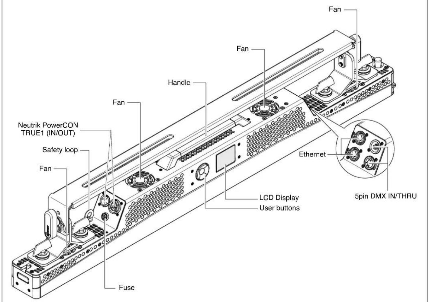
3
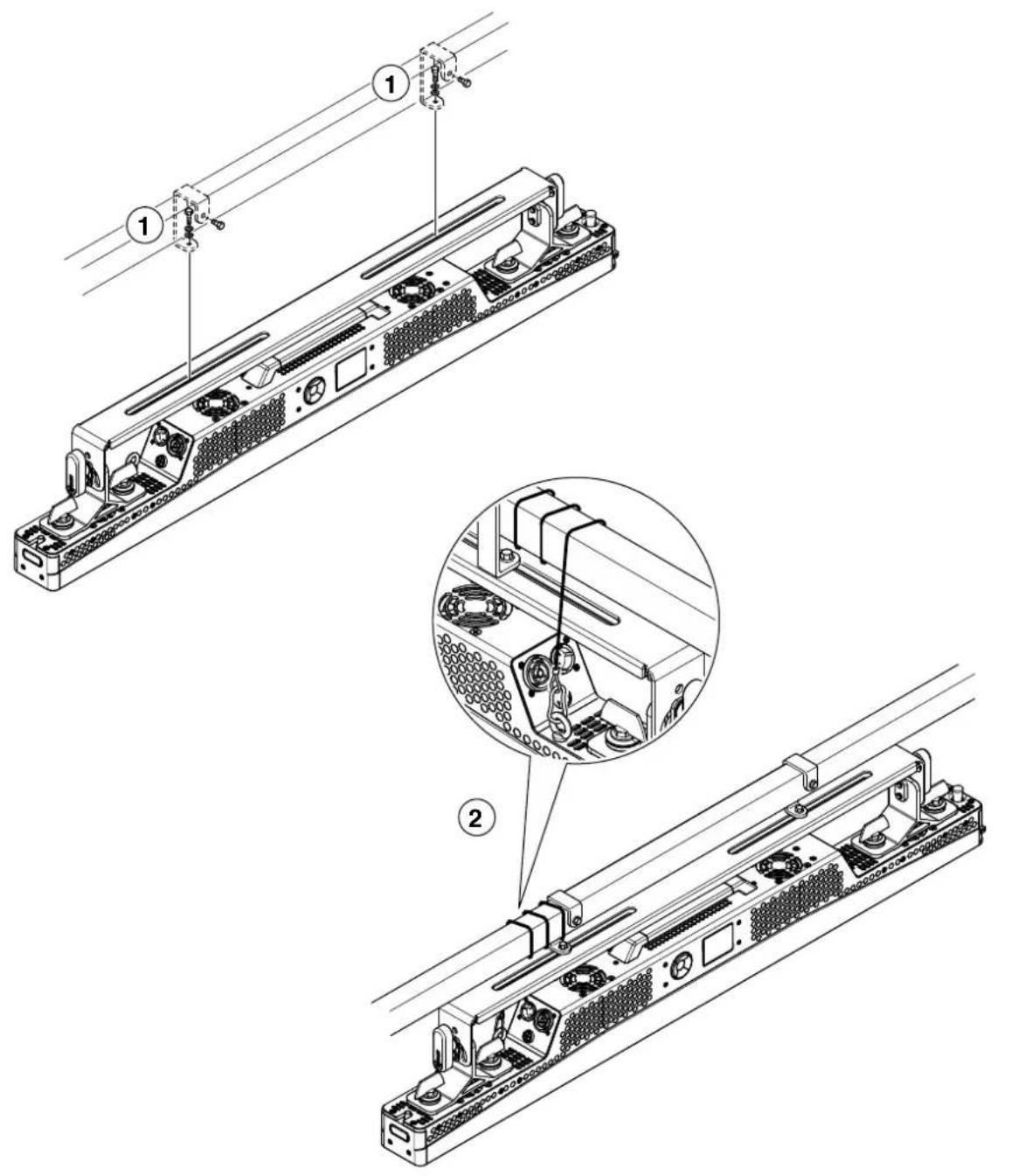

Projector installation - Fig. 3
The projector can be installed on the floor resting on specific rubber feet, on a truss, on the ceiling or wall.
WARNING: the safety chain must be installed except when the projector rests on the floor. (Code 105041-003 available upon request).
This must be secured to the projector support structure and then hooked to the fastening point at the centre of the fixture.
3.3 Connecting to mains supply
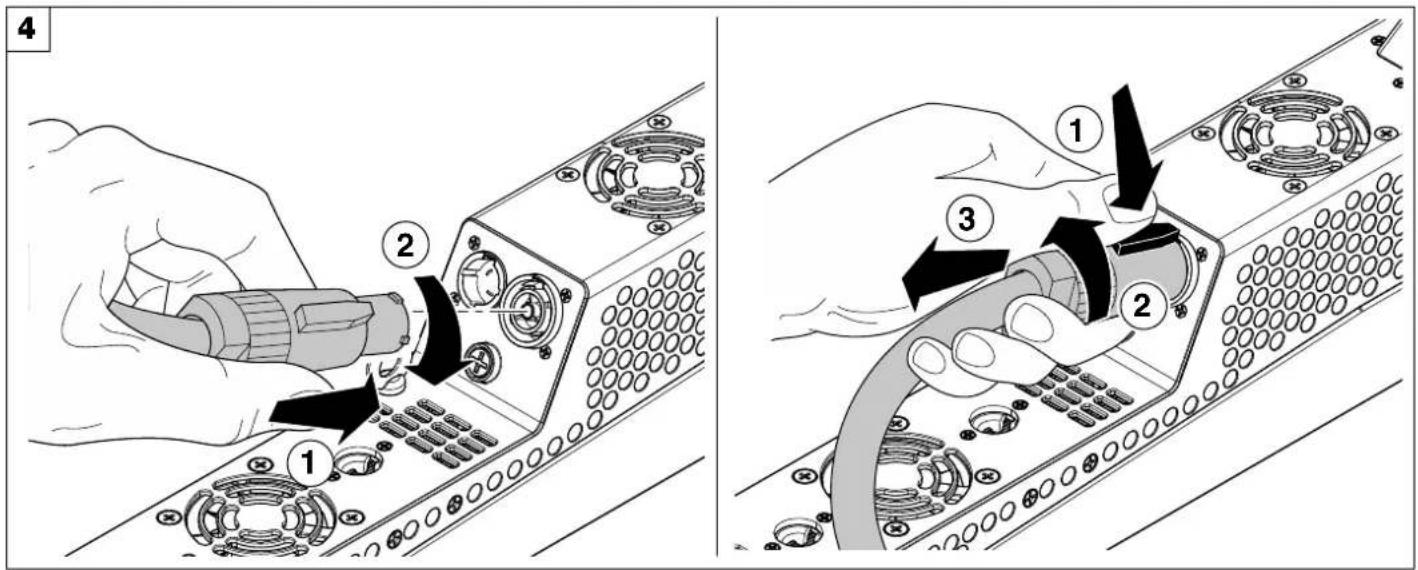
Connecting and disconnecting the power cord - Fig. 4
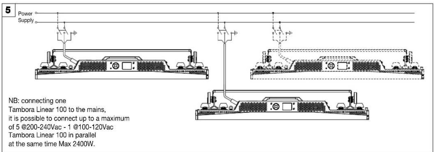
Connections to the power mains - Fig. 5
3.4 Connecting the control signal line: DMX / Art-Net
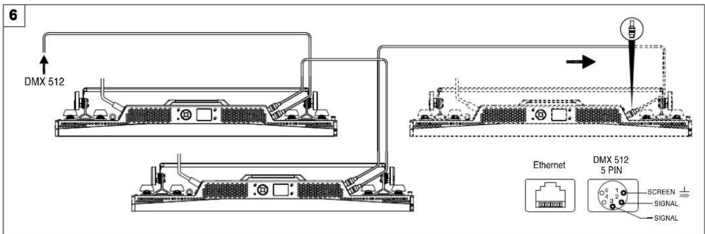
Connections to the control signal line (DMX) - Fig. 6
Use a cable conforming to specifications EIA RS-485: 2-pole twisted, shielded, 120Ω characteristic impedance, 22-24 AWG, low capacity. Do not use microphone cable or other cable with characteristics differing from those specified. End connections must be made using XLR type 5-pin male/female connectors. A terminating plug must be inserted on the last projector with a resistance of 120 (minimum 1/4 W) between terminals 2 and 3.
IMPORTANT: The wires must not make contact with each other or with the metal casing of the connectors. The casing must be connected to the shield braid and pin 1 of the connectors.
3.5 Switching on the fixture and basic SetUp
7
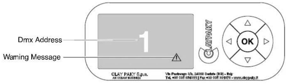
Switching on the projector - Fig. 7
Switch-on the fixture. The projector starts resetting the effects. At the same time, the following information scrolls on the display:

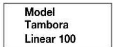
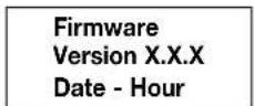
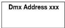
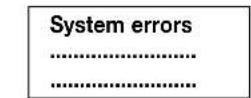
The control panel (Fig. 7) has a display and buttons for the complete programming and management of the projector menu. The display can be in one of two conditions: rest status and setting status. When it is in the rest status, the display shows the projector's DMX address.
During menu setting status, after a wait time (about 30 seconds) without any key having been pressed, the display automatically returns to rest status. It should be noted that when this condition occurs, any possible value that has been modified but not yet confirmed with the OK key will be cancelled.
8
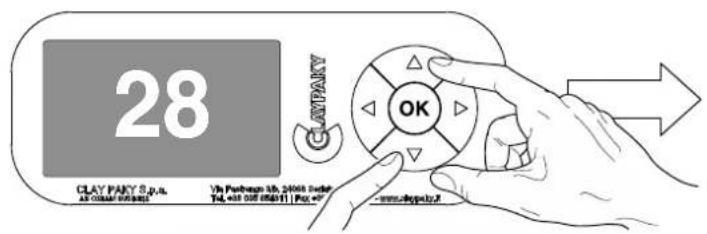

Reversal of the display - Fig. 8
To activate this function, press UP ⬆ and DOWN ⬇ keys simultaneously while the display is in the rest mode. This status will be memorised and maintained even for the next time it will be switched on. To return to the initial state, repeat the operation all over again.
Setting the projector starting address
On each projector, the starting address must be set for the control signal (addresses from 1 to 512).
The address can also be set with the projector switched off.
Functions of the buttons - Using the menu
| OK | Confirms the displayed value, or activates the displayed function, or enters the successive menu. |
| DOWN | Decreases the value displayed (with auto-repetitions) or passes to the next item in the menu. |
| UP | Increases the value displayed (with auto-repetitions) or passes to the previous item in a menu. |
| LEFT | Return to the top level |
| RIGHT | Enters the successive menu |
USING THE MENU:
1) Press LEFT ◆ once - "Main Menu" appears on the display.
2) Use the UP ⬆ and DOWN ⬇ keys to select the menu to be used:
- Setup (Setup Menu): To set the setting options.
- Option (Option Menu): To set the operating options
- Informations (Informations Menu): To read the counters, software version and other information.
- Manual Control (Manual control Menu): To trigger the test and manual control functions.
- Test (Test Menu): To check the proper functioning of effects
- Advanced (Advanced Menu): Access to the "Advanced menu" is recommended for a trained technical personnel.
3) Press Ⓞ to display the first item in the selected menu.
4) Use the UP ▲ and DOWN ▼ keys to select the MENU items.
Setting addresses and options with the projector disconnected
The projector's DMX address, as well as other possible operating options, can also be set when the appliance is disconnected from the electricity supply. All that is needed is to press RIGHT ▶ to momentarily activate the display and thus access the settings. Once the required operations have been carried out, the display will switch off again after a wait time of 30 seconds.
4. MAINTENANCE
4.1 Fuses replacing
9
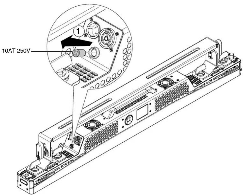
Fuse replacing - Fig. 9
Each Tambora Linear 100 has 1 fuse 10AT 250V, associated with the main power cord connection.
4.2 Periodical cleaning & Caution
10
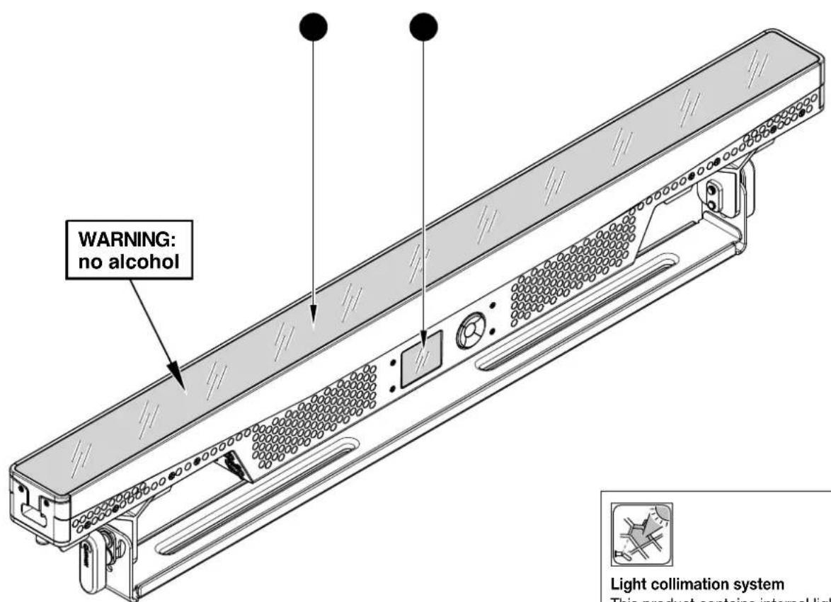

This product contains internal light collimation system. Avoid intense light from any angle.
● Parts requiring frequent cleaning.
CAUTION:
- To ensure optimal operation and performance for a long time it is essential to periodically clean the parts subject to dust and grease deposits. The frequency with which the following operations are to be carried out depends on various factors, such as the amount of the effects and the quality of the working environment (air humidity, presence of dust, salinity, etc.).
It is recommended that the projector undergoes an annual service by a qualified technician for special maintenance involving at least the following operations:
- General cleaning of internal parts.
- General visual check of the internal components, cabling, mechanical parts, etc.
- Electrical, photometric and functional checks; eventual repairs.
Cleaning the LED cover
Only use neutral soap and water to clean the LED cover, then dry it carefully with a soft, non-abrasive cloth. (WARNING: the use of alcohol or any other detergent could damage the LED cover).
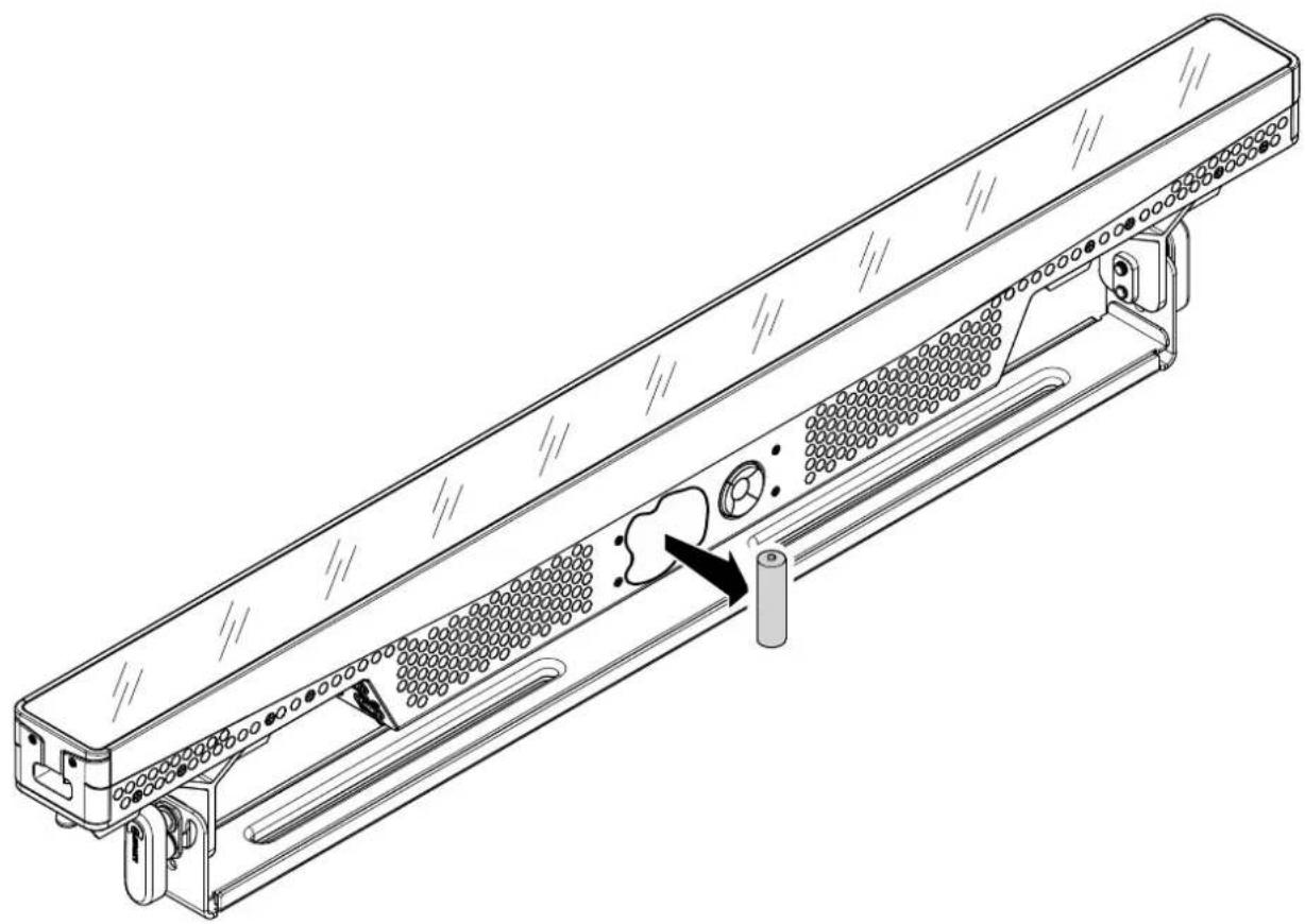
4.3 Battery removal
11
natural_image
Technical line drawing of a mechanical device with internal components and a circular component, no text or symbols present.
This product contains a rechargeable battery. To preserve the environment, please dispose the battery at the end of its life according to the regulation in force.
- DIMENSIONS
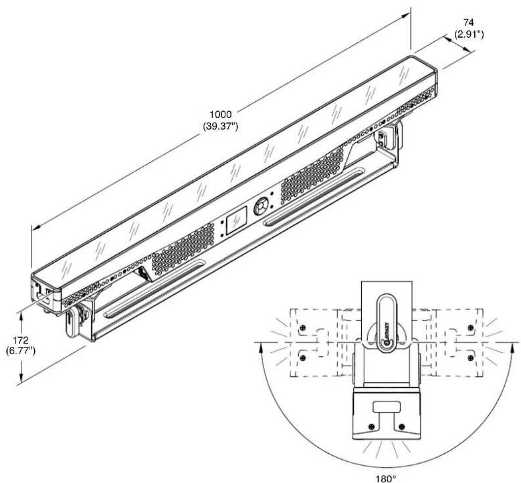
Rotating angle
- CAUSE AND SOLUTION OF PROBLEMS
| THE PROJECTOR WILL NOT SWITCH ON | TROUBLE | |||||
| ELECTRONICS NON-OPERATIONAL | ||||||
| DEFECTIVE PROJECTION | ||||||
| REDUCED LUMINOSITY | ||||||
| POSSIBLE CAUSES | CHECKS AND REMEDIES | |||||
| ● | No power supply. | Check the power supply voltage. | ||||
| ● | ● | LED burnt out or defective. | Call an authorised technician. | |||
| ● | Signal transmission cable faulty or disconnected. | Replace the cables. | ||||
| ● | Incorrect addressing. | Check addresses (see instructions). | ||||
| ● | Fault in the electronic circuits. | Call an authorised technician. | ||||
| ● | Optic fault. | Call an authorised technician. | ||||
| ● | ● | Dust or grease deposits. | Clean (see instructions). | |||
- SAFETY INFORMATION
- EN
- SAFETY INFORMATION
- IT
- ES
- FR
- CONSIGNES DE SÉCURITÉ
- INSTALLATION AND START-UP
- Fixture overview
- Connecting to mains supply
- Connecting the control signal line: DMX / Art-Net
- Switching on the fixture and basic SetUp
- Functions of the buttons - Using the menu
- USING THE MENU:
- Setting addresses and options with the projector disconnected
- MAINTENANCE
- Fuses replacing
- Periodical cleaning & Caution
- CAUTION:
- Cleaning the LED cover
- Battery removal
Brand : Claypaky
Model : Tambora Linear 100
Category : Lighting