
AP-0622 - Access Point ZEBRA - Free user manual and instructions
Find the device manual for free AP-0622 ZEBRA in PDF.


| Product Type | Access Point |
| Brand | Zebra |
| Model | AP-0622 |
| Wireless Standard | IEEE 802.11ac Wave 2 |
| Frequency Bands | 2.4 GHz and 5 GHz |
| Maximum Data Rate | Up to 1.73 Gbps |
| Ethernet Ports | 1 x 10/100/1000 Mbps (PoE) |
| Power Supply | Power over Ethernet (802.3af/at) or 12V DC adapter |
| Dimensions (W x D x H) | 20.3 cm x 20.3 cm x 3.8 cm |
| Weight | 0.45 kg |
| Mounting | Ceiling or wall mount (bracket included) |
| Security | WPA2, WPA3, 802.1X, RADIUS |
| Management | Web interface, SNMP, Cloud management |
| LED Indicators | Status, Power, Ethernet, Wireless |
| Operating Temperature | 0°C to 40°C |
| Storage Temperature | -20°C to 70°C |
| Humidity | 10% to 90% non-condensing |
| Certifications | FCC, CE, IC |
Frequently Asked Questions - AP-0622 ZEBRA
User questions about AP-0622 ZEBRA
0 question about this device. Answer the ones you know or ask your own.
Ask a new question about this device
Download the instructions for your Access Point in PDF format for free! Find your manual AP-0622 - ZEBRA and take your electronic device back in hand. On this page are published all the documents necessary for the use of your device. AP-0622 by ZEBRA.
USER MANUAL AP-0622 ZEBRA
AP-0622 Access Point
INSTALLATION GUIDE

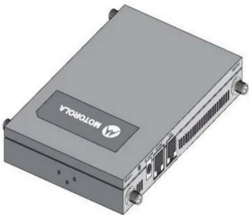
natural_image
3D rendering of a black rectangular electronic device labeled 'MOTOROLA' with ports and connectors (no readable text beyond label)MOTOROLA SOLUTIONS and the Stylized M Logo are registered in the US Patent & Trademark Office. © Motorola Solutions, Inc. 2011. All rights reserved.
1.0 Introduction ......4
1.1 Document Conventions 4
1.2Warnings 5
1.3 Site Preparation 5
1.4 AP-0622 Package Contents .... 5
2.0 Hardware Installation ....7
2.1 Installation Instructions .... 7
2.2 Precautions....7
2.3 Access Point Placement....8
2.4 Integrated Antenna Model Wall Mount Instructions .....8
2.5 Integrated Antenna Model Suspended Ceiling T-Bar Mount ....11
2.6 External Antenna Model Wall Mount Instructions ..... 12
2.7 External Antenna Model Suspended Ceiling T-Bar Mount ..... 15
2.8 External Antenna Suspended Ceiling Tile (Plenum) Mount.....17
2.9 AP-0622 External Antenna Model Antenna Options ..... 19
2.10 LED Indicators 21
3.0 Initial Access Point Configuration .....22
4.0 Specifications....23
4.1 AP-0622 Integrated Antenna Model Electrical Characteristics...23
4.2 AP-0622 Integrated Antenna Model Physical Characteristics . . . 23
4.3 AP-0622 External Antenna Model Electrical Characteristics ....24
4.4 AP-0622 External Antenna Model Physical Characteristics .....24
4.5 Radio Characteristics....25
5.0 Regulatory Information ....26
6.0 Part Numbers, Support, and Sales ....34
7.0 Motorola Solutions, Inc. End-User License Agreement . . . 35
8.0 AP-0622 Access Point China ROHS Compliance ..... 38
1 Introduction
The AP-0622 access point, a component of the Motorola Solutions wireless controller system, links wireless 802.11a/b/g/n devices to the controller, enabling the growth of your wireless network with a cost effective alternative to standard access points. The AP-0622 access point provides multiple deployment options.
The AP-0622 access point receives all power and transfers data through the same CAT-5 or better Ethernet cable. An 802.3af Ethernet switch or power supply (specifically rated for the AP-0622) is required (Part No. PWRS-14000-148R).
This guide applies to Model Number AP-0622.
This document is written for the qualified network device installer.
1.1 Document Conventions
The following graphical alerts are used in this document to indicate notable situations:

NOTE Tips, hints, or special requirements that you should take note of.

CAUTION Care is required. Disregarding a caution can result in data loss or equipment malfunction.

WARNING! Indicates a condition or procedure that could result in personal injury or equipment damage.
1.2 Warnings
- Read all installation instructions and site survey reports, and verify correct equipment installation before connecting the AP-0622 model access point.
- Remove jewelry and watches before installing this equipment.
- Verify the unit is grounded before connecting it to the power source.
- Verify any device connected to this unit is properly wired and grounded.
- Verify there is adequate ventilation around the device, and that ambient temperatures meet equipment operation specifications.
1.3 Site Preparation
- Consult your site survey and network analysis reports to determine specific equipment placement, power drops, and so on.
- Assign installation responsibility to the appropriate personnel.
- Identify and document where all installed components are located.
- Ensure adequate, dust-free ventilation to all installed equipment.
- Identify and prepare Ethernet and console port connections.
- Verify cable lengths are within the maximum allowable distances for optimal signal transmission.
1.4 AP-0622 Package Contents
An AP-0622 access point is available in integrated antenna and external antenna models. Contents differ depending on the model ordered.
1.4.1 External Antenna Model Package Contents
- AP-0622 access point with external antenna connectors (Plenum Rated)
- 2 customer installed mounting lugs
- 4 mounting lug retaining screws
• AP-0622 Installation Guide (This Guide)
1.4.2 Internal Antenna Model Package Contents
- AP-0622 access point with internal antennas
- AP-0622 Installation Guide (This Guide)
1.4.3 Features
- 2 RJ-45 connectors, one for 10/100/1000 Ethernet and the other for the serial/console connector
- LED indicators
- Slots for wall mounting
- Clips for mounting on a suspended ceiling T-bar (internal antenna model only) with separately orderable accessories
- Lock port for Kensington style Security Lock
The AP-0622 access point has one RJ-45 connector supporting an 10/100/1000 Ethernet port and accepts 802.3af-compliant power from an external source. The illustration below is of an integrated antenna model AP-0622.

NOTE When operating in a Gigabit Ethernet environment, CAT-5e or CAT-6 cable is recommended for Gigabit operation.
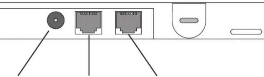
DC12V GE1/PoE Console
The AP-0622 access point comes with dual radios supporting 802.11a/b/g/n. The access point contains runtime firmware which enables the unit to boot after a power up or watchdog reset. The runtime firmware on the access point and the firmware downloaded from the connected controller can be updated via the Ethernet interface.
2 Hardware Installation
2.1 Installation Instructions
The AP-0622 access point mounts either on a wall (with customer supplied M4 x 25 pan head screws and wall anchor - or equivalent) or on a suspended ceiling T-bar. If deploying an external antenna model AP622, access point mounting kit (Part No. KT-135628-01) is required. An AP-0622 is not designed for mounting on a desk.
To prepare for the installation:
- Match the model number on the purchase order with the model numbers in the packing list and on the case of the access point.
- Verify the contents of the box include the intended AP-0622 access point, and he included hardware matches the package contents on page 4.
| Part Number Description | |
| AP-0622-66030-US 802.11n dependent access point, dual radio, internal antenna | |
| AP-0622-66040-US 802.11n dependent access point, dual radio, external antenna | |
| AP-0622-66030-WR 802.11n dependent access point, dual radio, internal antenna | |
| AP-0622-66040-WR 802.11n dependent access point, dual radio, external antenna | |

NOTE In the above part numbers, a country code of "WR" represents a world wide model, whereas "US" defines the model as only legally deployable in the United States.
- Review site survey and network analysis reports to determine the location and mounting position for the AP-0622 access point.
- Connect a CAT-5 or better Ethernet cable to a compatible 802.3af power source and run the cable to the installation site. Ensure there is sufficient slack on the cable to perform the installation steps.

NOTE When operating in a Gigabit Ethernet environment, CAT-5e or CAT-6 cable is recommended for Gigabit operation.
2.2 Precautions
Before installing an AP-0622 model Access Point, verify the following:
- Your using the correctly rated power supply for the AP-0622 (PWRS-14000-148R)
- Motorola Solutions recommends you do not to install the AP-0622 in wet or dusty areas.
- Verify the environment has a continuous temperature range between 0^ to 40^ .
2.3 Access Point Placement
For optimal performance, install the access point away from transformers, heavy-duty motors, fluorescent lights, microwave ovens, refrigerators and other industrial equipment. Signal loss can occur when metal, concrete, walls or floors block transmission. Install the access point in an open area or add access points as needed to improve coverage.
Antenna coverage is analogous to lighting. Users might find an area lit from far away to be not bright enough. An area lit sharply might minimize coverage and create dark areas. Uniform antenna placement in an area (like even placement of a light bulb) provides even, efficient coverage.
Place the access point using the following guidelines:
• Install the access point at an ideal height of 10 feet from the ground.
- Orient the access point antennas vertically for best reception (applies to external antenna models only).
To maximize the access point's radio coverage area, Motorola Solutions recommends conducting a site survey to define and document radio interference obstacles before installing the access point.
2.4 Integrated Antenna Model Wall Mount Instructions
This mounting requires hanging the AP-0622 along its width or length using the two slots on the bottom of the unit. The AP22 can be mounted onto any plaster, wood, or cement wall surface using customer supplied screw hardware (M3.5 x 0.6 x 20 mm- or equivalent).
2.4.1 Wall Mount Hardware
- Two wide-shoulder Phillips pan head self-tapping screws (customer supplied)
- Two wall anchors (customer supplied)
• Security cable (optional)

NOTE The following screws are recommended: (ANSI Standard) #6-18 X 0.875in. Type A or AB Self-Tapping Screw, or (ANSI Standard Metric) M3.5 X 0.6 X 20mm Type D Self-Tapping Screw.
2.4.2 Wall Mount Procedure
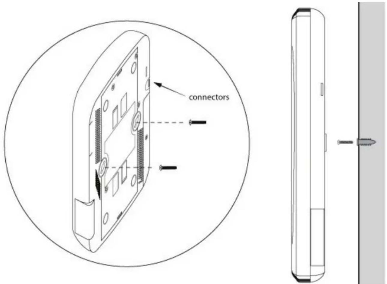
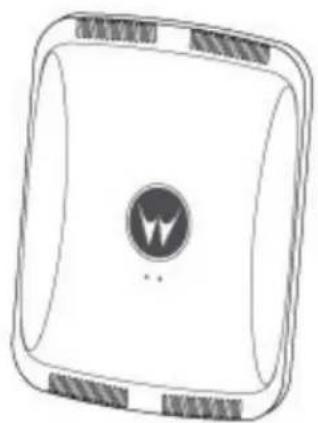
- Orient the case on the wall by its width or length.
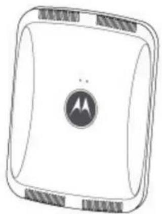
natural_image
Simple line drawing of a square device with a central circular logo (no text or symbols)Correct Orientation
natural_image
Simple line drawing of a square device with a central circular symbol and textured edges (no text or labels)Incorrect Orientation

CAUTION To ensure proper operation of an AP-0622 access point, ensure it is mounted in the correct orientation as shown above.
- Mark two points (for drill holes) 4.08 inches (103.7 mm) apart on a horizontal line.
- At each point, drill a hole in the wall, insert an anchor, screw into the anchor the wall mounting screw and stop when there is 1mm between the screw head and the wall.

NOTE When pre-drilling a hole the recommended hole size is 2.8mm (0.11in.).
- If required, install and attach a Kennsington security cable (customer supplied) to the unit's lock port.
- Attach an Ethernet cable from the access point to a controller with an 802.3af-compatible power source or use the PWRS-14000-148R power supply to supply power to the AP-0622 (once fully cabled).
- Place the middle of each of the case's mount slots over the screw heads.
- Slide the case down along the mounting surface to hang the mount slots on the screw heads.
- Verify the unit has power by observing that the LEDs are lit or flashing.

CAUTION If not using a 802.3af capable controller to power the AP-0622, ensure only the AP-0622's designated power supply (PWRS-14000-148R) is used to supply power to the access point. Using an incorrectly rated power supply could damage the unit and void the product warranty. Do not actually connect to the power source until the cabling portion of the installation is complete.
2.5 Integrated Antenna Model Suspended Ceiling T-Bar Mount
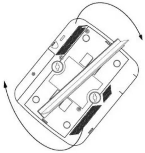
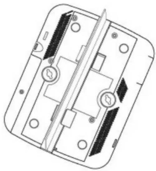
Ceiling mount requires holding the AP-0622 access point up against a T-bar of a suspended ceiling grid and twisting the case onto the T-bar.
2.5.1 Suspended Ceiling T-Bar Mount Procedure
natural_image
Diagram of a smartphone showing internal components and directional arrows indicating rotation (no text or symbols)Plastic Under Ceiling Mount A
natural_image
Technical line drawing of a mechanical component with internal parts and mounting holes (no text or symbols)Plastic Under Ceiling Mount B
- If required, install and attach a Kensington security cable (customer supplied) to the unit's lock port.
- Attach an Ethernet cable from the access point to a controller with an 802.3af compatible power source or use the PWRS-14000-148R power supply to supply power to the AP-0622 (once fully cabled).
- Align the bottom of the T-bar with the back of the case.
- Orient the case by its length, and the length of the T-bar.
- Rotate the case 45 degrees clockwise, or about 10 o'clock.
- Push the back of the case onto the bottom of the T-bar.
- Rotate the case 45 degrees counter-clockwise. The clips click as they fasten to the T-bar.
- Verify the unit has power by observing the LEDs.

CAUTION If not using a 802.3af capable controller to power the AP-0622, ensure only the AP-0622's designated power supply (PWRS-14000-148R) is used to supply power to the access point. Using an incorrectly rated power supply could damage the unit and void the product warranty. Do not actually connect to the power source until the cabling portion of the installation is complete.
2.6 External Antenna Model Wall Mount Instructions
A wall mount deployment requires hanging the AP-0622 access point along its width or length using the pair of slots on the bottom of the unit. The AP-0622 can be mounted on to any plaster, wood or cement wall surface using the provided wall anchors.
2.6.1 Wall Mount Hardware
- Two customer provided wide-shoulder Phillips pan head self-tapping screws (M3.5 x 0.6 x 20 mm)
- Two wall anchors (customer supplied)
• Security cable (optional)

NOTE The following screws are recommended: (ANSI Standard) #6-18 X 0.875in. Type A or AB Self-Tapping Screw, or (ANSI Standard Metric) M3.5 X 0.6 X 20mm Type D Self-Tapping Screw.
2.6.2 Wall Mount Procedure - New Installation
This section describes a new AP-0622 installation with no previous access point existing on the intended wall surface.
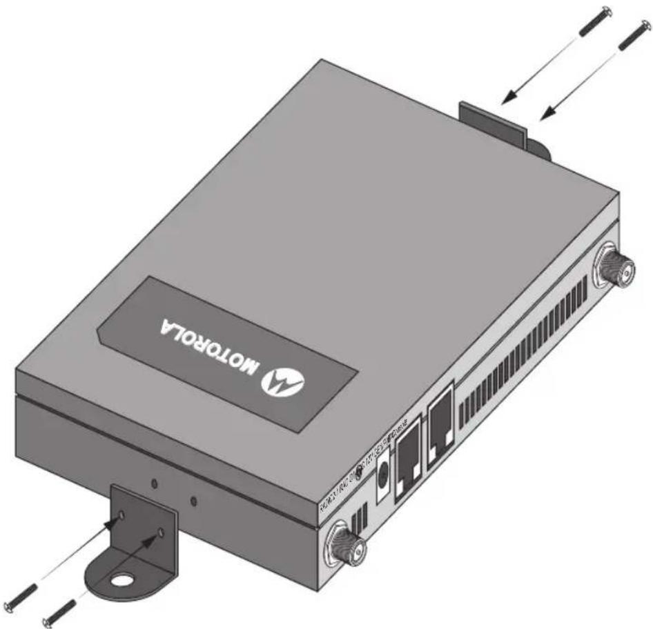
- Attach the two provided mounting ears (using four ear mounting screws) to the two narrow ens of the AP-0622. Align the ears using the built in ear alignment pin on the access point housing. Torque the screws to 6 lb-in.
natural_image
3D rendering of a motorola device with ports and connectors, shown without any text or symbols on the device itself.-
Place the access point against the wall, ensuring the access point's Motorola Solutions "bat wings" logo is in the correct orientation.
-
Mark the screw hole locations on a vertical axis using the ear's mounting holes.
-
At each point, drill a hole in the wall and insert the anchor.

NOTE When pre-drilling a hole the recommended hole size is 2.8mm (0.11in.).
-
Place the access point on the anchor. Insert screws through the access point's mounting ears and into the anchor.
-
If required, install and attach a Kensington security cable (customer supplied) to the unit's lock port.
-
Attach an Ethernet cable from the access point to a controller with an 802.3af-compatible power source or use the PWRS-14000-148R power supply to supply power to the AP-0622 (once fully cabled).
-
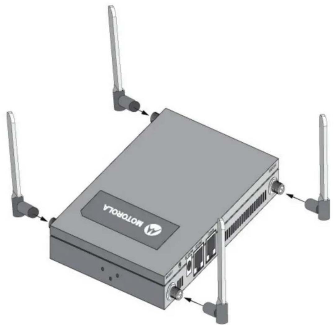
Attach appropriate antennas to the connectors.
-
Attach an Ethernet cable from the access point to a controller with an 802.3af compatible power source.
-
Verify the access point is receiving power by observing that the LEDs are lit or flashing.

CAUTION If not using a 802.3af capable controller to power the AP622, ensure only the AP622's designated power supply (PWRS-14000-148R) is used to supply power to the access point. Using an incorrectly rated power supply could damage the unit and void the product warranty. Do not actually connect to the power source until the cabling portion of the installation is complete.
2.6.3 Wall Mount Procedure - Existing Access Point Replacement
An existing external antenna model AP300 (WSAP-5100-100) or external antenna model AP650 (AP-0650-660X0) access point, installed on a wall (plenum installation), can be placed by an AP-0622. Simply remove the existing legacy model access point form its mounting screws, leave the mounting hardware in place and install the new external antenna model AP-0622 directly on to the existing mounting hardware. The cabling procedure for such a replacement is as described in the previous section.
2.7 External Antenna Model Suspended Ceiling T-Bar Mount
Ceiling mount requires holding the AP-0622 access point up against a T-bar of a suspended ceiling grid and the case onto the T-bar. If deploying an external antenna model AP-0622 on a ceiling T-Bar, access point must kit (Part No. KT-135628-01) or ceiling mount hardware (SCT-2) is required.
2.7.1 Suspended Ceiling T-Bar Mount Procedure - Using Mounting Kit
The following installation uses the access point mounting kit (Part No. KT-135628-01) to deploy the access on a ceiling T-Bar.
- If required, install and attach a Kensington security cable (customer provided) to the unit's lock port.
- Using only the mounting bracket from the mounting kit, rotate and click the mounting bracket into the most slots on the AP-0622.
- Attach an Ethernet cable from the access point to a controller with an 802.3af compatible power source or the PWRS-14000-148R power supply to supply power to the AP-0622 (once fully cabled).
- With the ceiling tile raised, slip the T-Bar bracket on to the exposed T-Bar flange.
- Lower the ceiling tile and verify the stability of the T-Bar mounting bracket connection. There will be no stability in this assembly until the ceiling tile is lowered on to the T-Bar to secure the mounting hardware.
- Verify the unit has power by observing the LEDs.

CAUTION If not using a 802.3af capable controller to power the AP-0622, ensure only the AP-0622's designated power supply (PWRS-14000-148R) is used to supply power to the access point. Using an incorrectly rated power supply could damage the unit and void the product warranty. Do not actually connect to the power source until the cabling portion of the installation is complete.
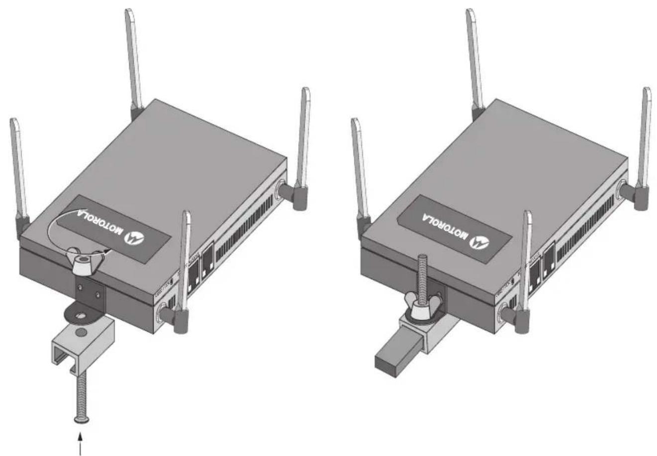
2.7.2 Suspended Ceiling T-Bar Mount Procedure - Using Ceiling Mount Hardware
The following installation uses the access point ceiling mounting kit (Part No. SCT-2) to deploy the access | a ceiling T-Bar.
- If required, install and attach a Kensington security cable (customer provided) to the unit's lock port.
- Remove nut from the SCT-2 kit and place assembly and screw through access point mounting ear.
- Place the clips from the SCT-2 ceiling mount kit over ceiling T-Bar.
- Tighten clips using provided nuts.
natural_image
Two identical 3D diagrams of a motorola device with visible wiring and mounting bracket, no text or symbols present.- Attach an Ethernet cable from the access point to a controller with an 802.3af compatible power source or use the PWRS-14000-148R power supply to supply power to the AP-0622 (once fully cabled).
- Attach appropriate antennas to the connectors.
- Attach an Ethernet cable from the access point to the controller with an 802.3af compatible power source.
- Verify the unit has power by observing the LEDs.

CAUTION If not using a 802.3af capable controller to power the AP-0622, ensure only the AP-0622's designated power supply (PWRS-14000-148R) is used to supply power to the access point. Using an incorrectly rated power supply could damage the unit and void the product warranty. Do not actually connect to the power source until the cabling portion of the installation is complete.
2.8 External Antenna Suspended Ceiling Tile (Plenum) Mount
Ceiling mount requires placing the AP-0622 access point above suspended ceiling tile.

NOTE Notes or warnings about suspended ceiling mounts apply to all installations where the unit is placed on suspended ceiling tile.

CAUTION Motorola Solutions does not recommend mounting the AP-0622 access point directly to any suspended ceiling tile with a thickness less than 12.7mm (0.5in.) or a suspended ceiling tile with an unsupported span greater than 660mm (26in.). Motorola Solutions strongly recommends fitting the AP-0622 access point with the supplied mounting ears and hanging the access point on a pipe or beam.
2.8.1 Suspended Ceiling Mount Hardware
• Security cable (optional)
- Mounting ears
- Customer supplied pipe or channel clamps
2.8.2 Ceiling Mount Procedure
- If possible, remove the ceiling tile from its frame and place it, finish side down, on a work surface.
- If required, install and attach a Kensington security cable (customer provided) to the unit's lock port.
- Place the access point on the ceiling tile or attach to a plenum beam or pipe using industry available clamps.
- Attach appropriate antennas to the connectors.
- Bring the tile into the ceiling space
- Attach an Ethernet cable from the access point to a controller with an 802.3af compatible power source or use the PWRS-14000-148R power supply to supply power to the AP-0622 (once fully cabled).
- Verify the access point is receiving power by observing the LEDs.
- Place the ceiling tile back in its frame.

CAUTION If not using a 802.3af capable controller to power the AP-0622, ensure only the AP-0622's designated power supply (PWRS-14000-148R) is used to supply power to the access point. Using an incorrectly rated power supply could damage the unit and void the product warranty. Do not actually connect to the power source until the cabling portion of the installation is complete.
2.9 AP-0622 External Antenna Model Antenna Options
Motorola Solutions supports two antenna suites for AP-0622 External Antenna models. One antenna suite supporting the 2.4 GHz band and another antenna suite supporting the 5 GHz band. Select an antenna model best suited to the intended operational environment of your access point.
natural_image
Illustration of a Motorola network device with visible ports and antennas (no text or symbols on the device itself)The 2.4 GHz antenna suite includes the following models:
| Part Number Antenna Type | |
| ML-2452-APA2-01 Dipole Antenna | |
| ML-2499-SD3-01R Patch Antenna | |
| ML-2499-HPA3-01R Omni Antenna | |
| ML-2452-PNA5-01R Panel Antenna | |
| ML-2452-PTA3M3-036 Omni Antenna | |
| ML-2452-APAG2A1-01 (Black)ML-2452-APAG2A1-02 (White) | Dipole Antenna |
The 5 GHz antenna suite includes the following models:
| Part Number Antenna Type | |
| ML-2452-APA2-01 Dipole Antenna | |
| ML-5299-PTA1-01R Patch Antenna | |
| ML-5299-HPA1-01R Omni Antenna | |
| ML-2452-PNA5-01R Panel Antenna | |
| ML-2452-PTA3M3-036 Omni Antenna | |
| ML-2452-APAG2A1-01 (Black)ML-2452-APAG2A1-02 (White) | Dipole Antenna |
For up-to-date information on supported antennas and antenna specifications, please refer to the Motorola Solutions Enterprise Wireless LAN Antenna Specification Guide available on the Motorola Solutions Web site.
2.10 LED Indicators
Both Integrated Antenna and External Antenna models have LED activity indicators on the front of the case. With the External Antenna models mounted above a ceiling, LEDs are at the center of an oval badge on the ceiling.
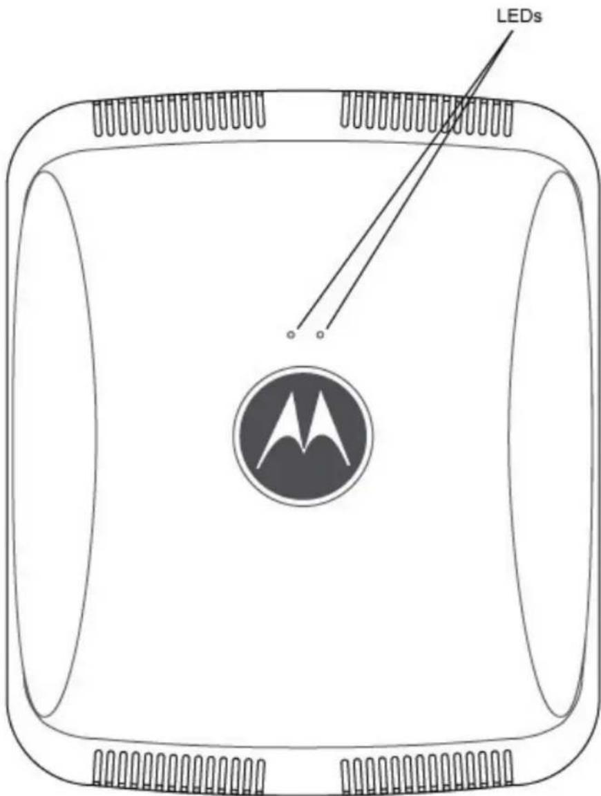
The LEDs provide a status display indicating error conditions, transmission, and network activity for the 5 GHz 802.11a/n (amber) radio or the 2.4 GHz 802.11b/g/n (green) radio.
| Task | 5 GHz Activity LED (Amber) | 2.4 GHz Activity LED (Green) |
| Unadopted Off | Blinking at 5Hz | |
| Normal Operation | If this radio band is enabled:Blink at 5 second intervalIf this radio band is disabled:OffIf there is activity on this band:Blink at a 1Hz | If this radio band is enabled:Blink at 5 second intervalIf this radio band is disabled:OffIf there is activity on this band:Blink at a 1Hz |
| Firmware Update | On Off | |
| Locate AP Mode | Blink at 5Hz Blink at 5Hz |
3 Initial Access Point Configuration
The AP-0622 access point receives its configuration once adopted by a Motorola Solutions RFS4000, RFS6000, RFS7000 or NX9000 series controller. There are no required initial configuration settings beyond verifying power and LED functionality for an AP-0622 model access point. Once adopted, the access point is managed by its connected controller and can receive periodic firmware updates when Motorola Solutions releases updates with new controller functionality.
For information on how use a Motorola Solutions RFS Series controller to manage an AP-0622 access point, refer to http://support.symbol.com/support/product/manuals.do.
4 Specifications
4.1 AP-0622 Integrated Antenna Model Electrical Characteristics
An AP-0622 Integrated model Access Point has the following electrical characteristics:
Operating Current & 12VDC, 1A (accessory power connector)
Voltage 48V,0.25A (PoE connector)
4.2 AP-0622 Integrated Antenna Model Physical Characteristics
An AP-0622 Integrated Antenna model Access Point has the following physical characteristics:
Dimensions 9.38 inches x 7.5 inches x 1.38 inches
23.82 cm x 19.50 cm x 3.50 cm
Housing Plastic
Weight 0.90 lbs / 0.40 kg
Operating 32^ F to 104^ F/ 0^ C to 40^ C
Temperature
Storage Temperature -40°F to 185°F/-40°C to 85°C
Operating Humidity 5 to 95% Relative Humidity non-condensing
Storage Humidity 85% Relative Humidity non-condensing
Operating Altitude 8,000 ft @ 28C
(max)
Storage Altitude 30,000 ft @ 12C
(max)
Electrostatic +/-15kV Air and +/-8kV Contact @ 50% Relative Humidity
Discharge
4.3 AP-0622 External Antenna Model Electrical Characteristics
An AP-0622 External Antenna model Access Point has the following electrical characteristics:
Operating Current & 12VDC, 1A (accessory power connector)
Voltage 48V,0.25A (PoE connector)
4.4 AP-0622 External Antenna Model Physical Characteristics
An AP-0622 External Antenna model Access Point has the following physical characteristics:
Dimensions 7.88 inches x 5.00 inches x 1.00 inches
20.01 cm x 12.70 cm x 2.54 cm
Housing Metal
Weight 1.45 lbs / 0.65 kg
Operating 32^ F to 104^ F/ 0^ C to 40^ C
Temperature
Storage Temperature -40°F to 185°F/-40°C to 85°C
Operating Humidity 5 to 95% Relative Humidity non-condensing
Storage Humidity 85% Relative Humidity non-condensing
Operating Altitude 8,000 ft @ 28C
(max)
Storage Altitude 30,000 ft @ 12C
(max)
Electrostatic +/-15kV Air and +/-8kV Contact @ 50% Relative Humidity
Discharge
4.5 Radio Characteristics
The AP-0622 model Access Points have the following radio characteristics:
| Operating Channels All channels from 4920 MHz to 5825 MHz except channel | |
| 52 -64 | |
| Channels 1-13 (2412-2472 MHz) | |
| Channel 14 (2484 MHz) Japan only | |
| Actual operating frequencies depend on regulatory approval for the country of use. | |
| Data Rates Supported 802.11b: 1,2,5.5,11Mbps | |
| 802.11g: 1,2,5.5,11,6,9,12,18,24,36,48, and 54Mbps | |
| 802.11a: 6,9,12,18,24,36,48, and 54Mbps | |
| 802.11n: MCS 0-15 up to 300Mbps | |
| Wireless Medium Direct Sequence Spread Spectrum (DSSS), | |
| Orthogonal Frequency Division Multiplexing (OFDM) | |
| Spatial multiplexing (MIMO) | |
| Network Standards 802.11a, 802.11b, 802.11g, 802.3, 802.11n (Draft 2.0) | |
| Maximum Available Transmit Power | Maximum available conducted transmit power per chain: 2.4 GHz: 21dBm |
| Maximum available conducted transmit power all chains: 2.4 GHz: 24dBm | |
| Maximum available conducted transmit power per chain: 5 GHz: 19dBm | |
| Maximum available conducted transmit power all chains: 5 GHz: 22dBm | |
| Transmit Power Adjustment | 1dB increments |
5 Regulatory Information
This device is approved under the Symbol Technologies, Inc. brand: Symbol Technologies, Inc. is a wholly owned subsidiary of Motorola Solutions, Inc. (collectively "Motorola").
This guide applies to Model Number AP-0622.
All Motorola/Symbol devices are designed to be compliant with rules and regulations in locations they are sold and will be labeled as required.
Local language translations are available at the following website: http://supportcentral.motorola.com/
Any changes or modifications to Motorola/Symbol Technologies equipment, not expressly approved by Motorola/Symbol Technologies, could void the user's authority to operate the equipment.
Motorola/Symbol devices are professionally installed, the Radio Frequency Output Power will not exceed the maximum allowable limit for the country of operation.
Antennas: Use only the supplied or an approved replacement antenna. Unauthorized antennas, modifications, or attachments could cause damage and may violate regulations.
This device is only to be used with a Motorola/Symbol Technologies Wireless Switch.
Country Approvals
Regulatory markings, subject to certification, are applied to the device signifying the radio(s) is/are approved for use in the following countries: United States, Canada, Japan, China, S. Korea, Australia, and Europe.
Please refer to the Declaration of Conformity (DoC) for details of other country markings. This is available at: http://www.motorola.com/doc
Note: For 2.4GHz or 5GHz Products: Europe includes, Austria, Belgium, Bulgaria, Czech Republic, Cyprus, Denmark, Estonia, Finland; For 2.4GHz or 5GHz Products: Europe includes, Austria, Belgium, Bulgaria, Czech Republic, Cyprus, Denmark, Estonia, Finland, France, Germany, Greece, Hungary, Iceland, Ireland, Italy, Latvia, Liechtenstein, Lithuania, Luxembourg, Malta, Netherlands, Norway, Poland, Portugal, Romania, Slovak Republic, Slovenia, Spain, Sweden, Switzerland and the United Kingdom.

Operation of the device without regulatory approval is illegal.
Health and Safety Recommendations
Country Selection
Select only the country in which you are using the device. Any other selection will make the operation of this device illegal.
Frequency of Operation – FCC and IC
You are reminded of the need to observe restrictions on the use of radio devices in fuel depots, chemical plants etc. and areas where the air contains chemicals or particles (such as grain, dust, or metal powders).
5 GHz Only
The use in the UNII (Unlicensed National Information Infrastructure) band 1 (5150-5250 MHz) is restricted to Indoor Use Only; any other use will make the operation of this device illegal.
Industry Canada Statement:
Caution: The device for the band 5150-5250 MHz is only for indoor usage to reduce potential for harmful interference to co-Channel mobile satellite systems. High power radars are allocated as primary users (meaning they have priority) of 5250-5350 MHz and 5650-5850 MHz and these radars could cause interference and/or damage to LE-LAN devices.
Health and Safety Recommendations
Warnings for Use of Wireless Devices

Please observe all warning notices with regard to the usage of wireless devices.
Potentially Hazardous Atmospheres - Fixed Installations
You are reminded of the need to observe restrictions on the use of radio devices in fuel depots, chemical plants etc. and areas where the air contains chemicals or particles (such as grain, dust, or metal powders).
Safety in Hospitals

Wireless devices transmit radio frequency energy and may affect medical electrical equipment. When installed adjacent to other equipment, it is advised to verify that the adjacent equipment is not adversely affected.
Pacemakers
Pacemaker manufacturers recommended that a minimum of 15cm (6 inches) be maintained between a handheld wireless device and a pacemaker to avoid potential interference with the pacemaker. These recommendations are consistent with independent research and recommendations by Wireless Technology Research.
Persons with Pacemakers:
- Should ALWAYS keep the device more than 15cm (6 inches) from their pacemaker when turned ON.
- Should not carry the device in a breast pocket.
- Should use the ear furthest from the pacemaker to minimize the potential for interference.
- If you have any reason to suspect that interference is taking place, turn OFF your device.
Other Medical Devices
Please consult your physician or the manufacturer of the medical device, to determine if the operation of your wireless product may interfere with the medical device.
RF Exposure Guidelines
Safety Information
Reducing RF Exposure - Use Properly
Only operate the device in accordance with the instructions supplied.
International
The device complies with internationally recognized standards covering human exposure to electromagnetic fields from radio devices. For information on “International” human exposure to electromagnetic fields refer to the Motorola/Symbol Declaration of Conformity (DoC) at: http://www.motorola.com/doc
EU
Remote and Standalone Antenna Configurations
To comply with EU RF exposure requirements, antennas that are mounted externally at remote locations or operating near users at stand-alone desktop of similar configurations must operate with a minimum separation distance of 20 cm from all persons.
US and Canada
Co-located statement
To comply with FCC RF exposure compliance requirement, the antennas used for this transmitter must not be co-located or operating in conjunction with any other transmitter/antenna except those already approved in this filling.
Remote and Standalone Antenna Configurations
To comply with FCC RF exposure requirements, antennas that are mounted externally at remote locations or operating near users at stand-alone desktop of similar configurations must operate with a minimum separation distance of 20 cm from all persons.
Power Supply
Use ONLY a LISTED Motorola, Type no. PWRS-14000-148R (12VDC @ 4.16A), direct plug-in power supply, marked Class 2 (IEC60950-1, SELV).
This device can be powered from a 802.3af compliant power source which is certified by the appropriate agencies.
Use of alternative Power Supply will invalidate any approvals given to this unit and may be dangerous.
Wireless Devices - Countries
Country Selection
Select only the country in which you are using the device. Any other selection will make the operation of this device illegal.

NOTE
The US only models (AP-0622-66030-US and AP-0622-66040-US) have the country code permanently set to the US. The (AP-0622-66030-WR and AP-0622-66040-WR) models cannot be configured for use in the US.
Operation in the US and Canada
The use on UNII (Unlicensed National Information Infrastructure) Band 1 5150-5250 MHz is restricted to indoor use only, any other use will make the operation of this device illegal.
The available channels for 802.11 b/g operation in the US are Channels 1 to 11. The range of channels is limited by firmware.
Radio Frequency Interference Requirements—FCC
This equipment has been tested and found to comply with the limits for a Class B digital device, pursuant to Part 15 of the FCC rules. These limits are designed to provide reasonable protection against harmful interference in a residential installation. This equipment generates, uses and can radiate radio frequency energy and, if not installed and used in accordance with the instructions, may cause harmful interference to radio communications. However there is no
guarantee that interference will not occur in a particular installation. If this equipment does cause harmful interference to radio or television reception, which can be determined by turning the equipment off and on, the user is encouraged to try to correct the interference by one or more of the following measures:
- Reorient or relocate the receiving antenna
- Increase the separation between the equipment and receiver
- Connect the equipment into an outlet on a circuit different from that to which the receiver is connected
- Consult the dealer or an experienced radio/TV technician for help.
Radio Transmitters (Part 15)
This device complies with Part 15 of the FCC Rules. Operation is subject to the following two conditions: (1) this device may not cause harmful interference, and (2) this device must accept any interference received, including interference that may cause undesired operation.
Radio Frequency Interference Requirements – Canada
This Class B digital apparatus complies with Canadian ICES-003.
The use of 5 GHz RLAN's, for use in Canada, have the following restrictions:
• Restricted Band 5.60 – 5.65 GHz
This device complies with RSS 210 of Industry Canada. Operation is subject to the following two conditions: (1) this device may not cause harmful interference and (2) this device must accept any interference received, including interference that may cause undesired operation.
Label Marking: The Term "IC:" before the radio certification signifies that Industry Canada technical specifications were met.

CE Marking and European Economic Area (EEA)
The use of 2.4GHz RLAN's, for use through the EEA, have the following restrictions:
• Maximum radiated transmit power of 100 mW EIRP in the frequency range 2.400 -2.4835 GHz.
- France outside usage, the equipment is restricted to 2.400-2.45 GHz frequency range.
- Italy requires a user license for outside usage.
Statement of Compliance
Motorola hereby, declares that this device is in compliance with the essential requirements and other relevant provisions of Directive 1999/5/EC. A Declaration of Conformity may be obtained from http://www.motorola.com/doc.
Korea Warning Statement for Class B
Use of 5GHz RLAN's in Australia is restricted in the following band 5.50 – 5.65GHz.
Brazil
Restrict Frequency Range to: 2.450 - 2.4835 GHz.
Taiwan
臺灣
低功率電波輻射性電機管理辦法
第十二條
Turkish WEEE Statement of Compliance
Waste Electrical and Electronic Equipment (WEEE)
English: For EU Customers: All products at the end of their life must be returned to Motorola for recycling. For information on how to return product, please go to: http://www.motorola.com/recycling/weee.
Part Numbers, Support, and Sales
| Part Number Description | |
| AP-0622-66030-US 802.11n dependent access point, dual radio, internal antenna | |
| AP-0622-66040-US 802.11n dependent access point, dual radio, external antenna | |
| AP-0622-66030-WR 802.11n dependent access point, dual radio, internal antenna | |
| AP-0622-66040-WR 802.11n dependent access point, dual radio, external antenna | |
Motorola's Enterprise Mobility Support Center
If you have a problem with your equipment, contact Enterprise Mobility support for your region. Support and issue resolution is provided for products under warranty or that are covered by an Enterprise Mobility Services agreement. Contact information and web self-service is available by visiting http://supportcentral.motorola.com/.
When contacting Enterprise Mobility support, please provide the following information:
- Serial number of the unit
- Model number or product name
- Software type and version number
Motorola Solutions responds to calls by email or telephone within the time limits set forth in support agreements. If you purchased your Enterprise Mobility business product from a Motorola Solutions business partner, contact that business partner for support.
Customer Support Web Sites
Motorola Solutions' Support Central Web site, located at http://supportcentral.motorola.com/ provides information and online assistance including developer tools, software downloads, product manuals and online repair requests.
Manuals
http://support.symbol.com/support/product/manuals.do
6 Motorola Solutions, Inc. End-User License Agreement
BY DOWNLOADING, INSTALLING, OR USING THE SOFTWARE DESCRIBED IN THIS DOCUMENT, YOU OR THE ENTITY OR COMPANY THAT YOU REPRESENT ("LICENSEE") ARE UNCONDITIONALLY CONSENTING TO BE BOUND BY AND ARE BECOMING A PARTY TO THIS LICENSE AGREEMENT ("AGREEMENT"). LICENSEE'S USE OR CONTINUED USE OF THE DOWNLOADED OR INSTALLED MATERIALS SHALL ALSO CONSTITUTE ASSENT TO THE TERMS OF THIS AGREEMENT. IF LICENSEE DOES NOT UNCONDITIONALLY AGREE TO ALL OF THE TERMS OF THIS AGREEMENT, DO NOT CONTINUE THE INSTALLATION PROCESS. IF THESE TERMS ARE CONSIDERED AN OFFER, ACCEPTANCE IS EXPRESSLY LIMITED TO AND EXPRESSLY CONTINGENT UPON THESE TERMS. IF YOU ARE ACCEPTING THESE TERMS ON BEHALF OF A COMPANY, ANOTHER PERSON OR ANY OTHER LEGAL ENTITY, YOU REPRESENT AND WARRANTY THAT YOU HAVE THE AUTHORITY TO BIND THAT COMPANY, PERSON OR ENTITY.
1 LICENSE GRANT. Subject to the terms of this Agreement, Motorola, Inc. and/or its subsidiaries ("Licensor") hereby grants Licensee a limited, personal, non-sublicensable, non-transferable, nonexclusive license to use the software that Licensee is about to download or install and the documentation that accompanies it (collectively, the "Software") for Licensee's personal use in connection with hardware produced by Licensor and only in accordance with the accompanying documentation. Licensee may download, install and use the Software only on a single computer. Licensee may make one copy of the Software (excluding any documentation) for backup purposes, provided that copyright and other restricted rights notices of Licensor and its suppliers are reproduced exactly.
2 LICENSE RESTRICTIONS. Except as expressly permitted by this Agreement, Licensee shall not, nor permit anyone else to, directly or indirectly: (i) copy (except for one backup copy), modify, distribute or create derivative works based upon the Software; (ii) reverse engineer, disassemble, decompile or otherwise attempt to discover the source code or structure, sequence and organization of the Software; or (iii) rent, lease, or use the Software for timesharing or service bureau purposes, or otherwise use the Software for any commercial purpose/on behalf of any third party. Licensee shall maintain and not remove or obscure any proprietary notices on the Software, and shall reproduce such notices exactly on all permitted copies of the Software. All title, ownership rights, and intellectual property rights in and to the Software, and any copies or portions thereof, shall remain in Licensor and its suppliers or licensors. Licensee understands that Licensor may modify or discontinue offering the Software at any time. The Software is protected by the copyright laws of the United States and international copyright treaties. The Software is licensed, not sold. This Agreement does not give Licensee any rights not expressly granted herein.
3 INTELLECTUAL PROPERTY; CONTENT. All title and intellectual property rights in and to the Software (including but not limited to any images, photographs, animations, video, audio, music, text and "applets" incorporated into the Software), and any copies you are permitted to make herein are owned by Licensor or its suppliers. All title and intellectual property rights in and to the content which may be accessed through use of the Software is the property of the respective content owner and may be protected by applicable copyright or other intellectual property laws and treaties. This EULA grants you no rights to use such content. As a condition to Licensee's use of the Software, Licensee represents, warrants and covenants that Licensee will not use the Software: (i) to infringe the intellectual property rights or proprietary rights, or rights of publicity or privacy, of any third party; (ii) to violate any applicable law, statute, ordinance or regulation; (iii) to disseminate information or materials in any form or format ("Content") that are harmful, threatening, abusive, harassing, tortuous, defamatory, vulgar, obscene, libelous, or otherwise objectionable; or (iv) to disseminate any software viruses or any other computer code, files or programs that may interrupt, destroy or limit the functionality of any computer software or hardware or telecommunications equipment. Licensee, not Licensor, remains solely responsible for all Content that Licensee uploads, posts, e-mails, transmits, or otherwise disseminates using, or in connection with, the Software.
4 FEES; SUPPORT AND UPGRADES. Licensor may, at Licensor's sole option, provide support services related to the Software ("Support Services"). Nothing in this Agreement grants Licensee any right to receive any Support Services. Use of any Support Services provided is governed by the Licensor policies and programs described in the user manual, in "online" documentation, and/or in other Licensor-provided materials or support agreements. Any supplemental software code provided to you as part of any Support Services shall be considered part of the Software and subject to the terms and conditions of this EULA. With respect to technical information you provide to Licensor as part of any Support Services, Licensor may use such information for its business purposes, including for product support and development. Licensor will not utilize such technical information in a form that personally identifies Licensee.
5 TERMINATION. Either party may terminate this Agreement at any time, with or without cause, upon written notice. Any termination of this Agreement shall also terminate the licenses granted hereunder. Upon termination of this Agreement for any reason, Licensee
shall return all copies of the Software to Licensor, or destroy and remove from all computers, hard drives, networks, and other storage media all copies of the Software, and shall so certify to Licensor that such actions have occurred. Sections 2-13 shall survive termination of this Agreement.
6 DISCLAIMER OF WARRANTIES. To the maximum extent permitted by applicable law, Licensor and its suppliers provide the Software and any (if any) Support Services AS IS AND WITH ALL FAULTS, and hereby disclaim all warranties and conditions, either express, implied or statutory, including, but not limited to, any (if any) implied warranties or conditions of merchantability, of fitness for a particular purpose, of lack of viruses, of accuracy or completeness of responses, of results, and of lack of negligence or lack of workmanlike effort, all with regard to the Software, and the provision of or failure to provide Support Services. ALSO, THERE IS NO WARRANTY OR CONDITION OF TITLE, QUIET ENJOYMENT, QUIET POSSESSION, CORRESPONDENCE TO DESCRIPTION, OR NON-INFRINGEMENT WITH REGARD TO THE SOFTWARE. THE ENTIRE RISK AS TO THE QUALITY OF OR ARISING OUT OF USE OR PERFORMANCE OF THE SOFTWARE AND SUPPORT SERVICES, IF ANY, REMAINS WITH LICENSEE.
7 EXCLUSION OF INCIDENTAL, CONSEQUENTIAL AND CERTAIN OTHER DAMAGES. TO THE MAXIMUM EXTENT PERMITTED BY APPLICABLE LAW, IN NO EVENT SHALL LICENSOR OR ITS SUPPLIERS BE LIABLE FOR ANY GENERAL, SPECIAL, INCIDENTAL, DIRECT, INDIRECT, OR CONSEQUENTIAL DAMAGES WHATSOEVER (INCLUDING, BUT NOT LIMITED TO, DAMAGES FOR LOSS OF PROFITS OR CONFIDENTIAL OR OTHER INFORMATION, FOR BUSINESS INTERRUPTION, FOR PERSONAL INJURY, FOR LOSS OF PRIVACY, FOR FAILURE TO MEET ANY DUTY INCLUDING OF GOOD FAITH OR OF REASONABLE CARE, FOR NEGLIGENCE, AND FOR ANY OTHER PECUNIARY OR OTHER LOSS WHATSOEVER) ARISING OUT OF OR IN ANY WAY RELATED TO THE USE OF OR INABILITY TO USE THE SOFTWARE, THE PROVISION OF OR FAILURE TO PROVIDE SUPPORT SERVICES, OR OTHERWISE UNDER OR IN CONNECTION WITH ANY PROVISION OF THIS AGREEMENT, EVEN IN THE EVENT OF THE FAULT, TORT (INCLUDING NEGLIGENCE), STRICT LIABILITY, BREACH OF CONTRACT OR BREACH OF WARRANTY OF LICENSOR OR ANY SUPPLIER, AND EVEN IF LICENSOR OR ANY SUPPLIER HAS BEEN ADVISED OF THE POSSIBILITY OF SUCH DAMAGES.
8 LIMITATION OF LIABILITY AND REMEDIES. Notwithstanding any damages that Licensee might incur for any reason whatsoever (including, without limitation, all damages referenced above and all direct or general damages), the entire liability of Licensor and any of its suppliers under any provision of this Agreement and Licensee's exclusive remedy for all of the foregoing shall be limited to the greater of the amount actually paid by Licensee for the Software or U.S.\$5.00. The foregoing limitations, exclusions and disclaimers shall apply to the maximum extent permitted by applicable law, even if any remedy fails its essential purpose.
9 INDEMNITY. Licensee agrees that Licensor shall have no liability whatsoever for any use Licensee makes of the Software. Licensee shall indemnify and hold harmless Licensor from any claims, damages, liabilities, costs and fees (including reasonable attorney fees) arising from Licensee's use of the Software as well as from Licensee's failure to comply with any term of this Agreement.
10 FAULT TOLERANCE. The Software is not fault-tolerant and is not designed, manufactured or intended for use or resale in on-line control equipment in hazardous environments requiring fail-safe performance, such as, but not limited to, the operation of nuclear facilities, aircraft navigation or communication systems, air traffic control, life support machines, or weapons systems, in which the failure of the Software could lead directly or indirectly to death, personal injury, or physical or environmental damage ("High Risk Activities"). Licensor and its suppliers specifically disclaim any express or implied warranty of fitness for High Risk Activities.
11 U.S. GOVERNMENT LICENSE RIGHTS. Software provided to the U.S. Government pursuant to solicitations issued on or after December 1, 1995 is provided with the commercial license rights and restrictions described elsewhere herein. Software provided to the U.S. Government pursuant to solicitations issued prior to December 1, 1995 is provided with "Restricted Rights" as provided for in FAR, 48 CFR 52.227-14 (JUNE 1987) or DFAR, 48 CFR 252.227-7013 (OCT 1988), as applicable. The "Manufacturer" for purposes of these regulations is Motorola, Inc., One Symbol Plaza, Holtsville, NY 11742.
12 EXPORT RESTRICTIONS. Licensee shall comply with all export laws and restrictions and regulations of the Department of Commerce, the United States Department of Treasury Office of Foreign Assets Control ("OFAC"), or other United States or foreign agency or authority, and Licensee shall not export, or allow the export or re-export of the Software in violation of any such restrictions, laws or regulations. By downloading or using the Software, Licensee agrees to the foregoing and represents and warrants that Licensee is not located in, under the control of, or a national or resident of any restricted country.
13 MISCELLANEOUS. Licensee may not sublicense, assign, or transfer this Agreement, or its rights or obligations hereunder, without the prior written consent of Licensor. Any attempt to otherwise sublicense, assign, or transfer any of the rights, duties, or obligations hereunder is null and void. Licensor may assign this Agreement in its sole discretion. In the event that any of the provisions of this
Agreement shall be held by a court or other tribunal of competent jurisdiction to be illegal, invalid or unenforceable, such provisions shall be limited or eliminated to the minimum extent necessary so that this Agreement shall otherwise remain in full force and effect. No waiver or modification of this Agreement will be binding upon a party unless made in writing and signed by a duly authorized representative of such party and no failure or delay in enforcing any right will be deemed a waiver. This Agreement shall be governed by the laws of the State of New York without regard to the conflicts of law provisions thereof. The application the United Nations Convention of Contracts for the International Sale of Goods is expressly excluded. Unless waived by Licensor for a particular instance, any action or proceeding arising out of this Agreement must be brought exclusively in the state or federal courts of New York and Licensee hereby consents to the jurisdiction of such courts for any such action or proceeding. This Agreement supersedes all prior discussions and writings and constitutes the entire agreement between the parties with respect to the subject matter hereof. The prevailing party in any action arising out of this Agreement shall be entitled to costs and attorneys' fees.
7 AP-0622 Access Point China ROHS Compliance

natural_image
Two horizontal bars, one gray and one black, with no text or symbols present.| 部件名称(Parts) | 有毒有害物质或元素 | |||||
| 铅(Pb) | 汞(Hg) | 镉(Cd) | 六价铬( Cr^6+ ) | 多溴联苯(PBB) | 多溴二苯醚(PBDE) | |
| 金属部件(Metal Parts) | O | O | O | O | O | O |
| 电路模块(Circuit Modules) | X | O | O | O | O | O |
| 电缆及电缆组件(Cables and Cable Assemblies) | X | O | O | O | O | O |
| 塑料和聚合物部件(Plastic and Polymeric Parts) | O | O | O | O | O | O |
| 光学和光学组件(Optics and Optical Components) | O | O | O | O | O | O |
| 电池(Batteries) | O | O | O | O | O | O |
This table was created to comply with China RoHS requirements for Motorola Solutions' AP-0622 Access Point.

bar
| Category | Value | |---|---| | Category 1 | 100 | | Category 2 | 100 | | Category 3 | 100 | | Category 4 | 100 | | Category 5 | 100 | | Category 6 | 100 | | Category 7 | 100 | | Category 8 | 100 | | Category 9 | 100 | | Category 10 | 100 | | Category 11 | 100 | | Category 12 | 100 | | Category 13 | 100 | | Category 14 | 100 | | Category 15 | 100 | | Category 16 | 100 | | Category 17 | 100 | | Category 18 | 100 | | Category 19 | 100 | | Category 20 | 100 | | Category 21 | 100 | | Category 22 | 100 | | Category 23 | 100 | | Category 24 | 100 | | Category 25 | 100 | | Category 26 | 100 | | Category 27 | 100 | | Category 28 | 100 | | Category 29 | 100 | | Category 30 | 100 | | Category 31 | 100 | | Category 32 | 100 | | Category 33 | 100 | | Category 34 | 100 | | Category 35 | 100 | | Category 36 | 100 | | Category 37 | 100 | | Category 38 | 100 | | Category 39 | 100 | | Category 40 | 100 | | Category 41 | 100 | | Category 42 | 100 | | Category 43 | 100 | | Category 44 | 100 | | Category 45 | 100 | | Category 46 | 100 | | Category 47 | 100 | | Category 48 | 100 | | Category 49 | 100 | | Category 50 | 100 | | Category 51 | 100 | | Category 52 | 100 | | Category 53 | 100 | | Category 54 | 100 | | Category 55 | 100 | | Category 56 | 100 | | Category 57 | 100 | | Category 58 | 100 | | Category 59 | 100 | | Category 60 | 100 | | Category 61 | 100 | | Category 62 | 100 | | Category 63 | 100 | | Category 64 | 100 | | Category 65 | 100 | | Category 66 | 100 | | Category 67 | 100 | | Category 68 | 100 | | Category 69 | 100 | | Category 70 | 100 | | Category 71 | 100 | | Category 72 | 100 | | Category 73 | 100 | | Category 74 | 100 | | Category 75 | 100 | | Category 76 | 100 | | Category 77 | 100 | | Category 78 | 100 | | Category 79 | 100 | | Category 80 | 100 | | Category 81 | 100 | | Category 82 | 100 | | Category 83 | 100 | | Category 84 | 100 | | Category 85 | 100 | | Category 86 | 100 | | Category 87 | 100 | | Category 88 | 100 | | Category 89 | 100 | | Category 90 | 100 | | Category 91 | 100 | | Category 92 | 100 | | Category 93 | 100 | | Category 94 | 100 | | Category 95 | 100 | | Category 96 | 100 | | Category 97 | 100 | | Category 98 | 100 | | Category 99 | 100 | | Total (Total) |
MOTOROLA
Motorola Solutions, Inc.
1301 E. Algonquin Rd.
Schaumburg, IL 60196-1078, U.S.A.
http://www.motorolasolutions.com
MOTOROLA, MOTO, MOTOROLA SOLUTIONS and the Stylized M Logo are trademarks or registered trademarks of Motorola Trademark Holdings, LLC and are used under license. All other trademarks are the property of their respective owners.
© 2011 Motorola Solutions, Inc. All Rights Reserved.

72-157808-01 Revision A
December 2011

- AP-0622 Access Point
- INSTALLATION GUIDE
- Introduction ......4
- Hardware Installation ....7
- Initial Access Point Configuration .....22
- Specifications....23
- Regulatory Information ....26
- Part Numbers, Support, and Sales ....34
- Motorola Solutions, Inc. End-User License Agreement . . . 35
- AP-0622 Access Point China ROHS Compliance ..... 38
- Introduction
- Document Conventions
- Warnings
- Site Preparation
- AP-0622 Package Contents
- External Antenna Model Package Contents
- Internal Antenna Model Package Contents
- Features
- Hardware Installation
- Installation Instructions
- Precautions
- Access Point Placement
- Integrated Antenna Model Wall Mount Instructions
- Wall Mount Hardware
- Wall Mount Procedure
- Integrated Antenna Model Suspended Ceiling T-Bar Mount
- Suspended Ceiling T-Bar Mount Procedure
- External Antenna Model Wall Mount Instructions
- Wall Mount Hardware
- Wall Mount Procedure - New Installation
- Wall Mount Procedure - Existing Access Point Replacement
- External Antenna Model Suspended Ceiling T-Bar Mount
- Suspended Ceiling T-Bar Mount Procedure - Using Mounting Kit
- Suspended Ceiling T-Bar Mount Procedure - Using Ceiling Mount Hardware
- External Antenna Suspended Ceiling Tile (Plenum) Mount
- Suspended Ceiling Mount Hardware
- Ceiling Mount Procedure
- AP-0622 External Antenna Model Antenna Options
- LED Indicators
- Initial Access Point Configuration
- Specifications
- AP-0622 Integrated Antenna Model Electrical Characteristics
- AP-0622 Integrated Antenna Model Physical Characteristics
- AP-0622 External Antenna Model Electrical Characteristics
- AP-0622 External Antenna Model Physical Characteristics
- Radio Characteristics
- Regulatory Information
- Country Approvals
- Health and Safety Recommendations
- Country Selection
- Frequency of Operation – FCC and IC
- GHz Only
- Industry Canada Statement:
- Warnings for Use of Wireless Devices
- Potentially Hazardous Atmospheres - Fixed Installations
- Safety in Hospitals
- Pacemakers
- Other Medical Devices
- RF Exposure Guidelines
- Safety Information
- Reducing RF Exposure - Use Properly
- International
- EU
- Remote and Standalone Antenna Configurations
- US and Canada
- Co-located statement
- Power Supply
- Wireless Devices - Countries
- NOTE
- Operation in the US and Canada
- Radio Frequency Interference Requirements—FCC
- Radio Transmitters (Part 15)
- Radio Frequency Interference Requirements – Canada
- CE Marking and European Economic Area (EEA)
- Statement of Compliance
- Brazil
- Taiwan
- 臺灣
- 第十二條
- Turkish WEEE Statement of Compliance
- Waste Electrical and Electronic Equipment (WEEE)
- Part Numbers, Support, and Sales
- Motorola's Enterprise Mobility Support Center
- Customer Support Web Sites
- Manuals
- Motorola Solutions, Inc. End-User License Agreement
- AP-0622 Access Point China ROHS Compliance
- MOTOROLA
Brand : ZEBRA
Model : AP-0622
Category : Access Point