
T-1 - Satellite Transmitter YSI - Free user manual and instructions
Find the device manual for free T-1 YSI in PDF.


| Type of product | Satellite Transmitter |
| Model | YSI T-1 |
| Dimensions | 6 in x 8 in x 1.5 in (152 mm x 203 mm x 38 mm) |
| Weight | Approximately 1.5 lbs (0.68 kg) |
| Power supply | 12 VDC lead-acid battery (input range typical for 12V systems) |
| Average power consumption | Under 4 mA at 12.5V (typical sleep mode 2 mA) |
| Main functions | GOES (300/1200 bps) and METEOSAT/EUMETSAT (100/1200 bps) satellite data transmission; GPS time sync and TCXO calibration; failsafe monitor; USB and RS-232 interface |
| Satellite compatibility | NOAA GOES (Version 2.0), METEOSAT/EUMETSAT, CGMS International Channels |
| Data rates | 100 bps, 300 bps, 1200 bps |
| Transmit power | Adjustable, typical 0.8-5.0 W depending on antenna and rate |
| GPS receiver | Internal, used for time synchronization and TCXO calibration |
| Temperature operating range | -40°C to +50°C (certified); -42°C to +52°C for transmission enable |
| Failsafe monitor | Independent TKM monitor for message too long/too soon; manual reset via push-button or external interface |
| LED indicators | Red (FS), Green (TX), Green (GPS), Green (DATA) |
| Connectors | RF OUT (SMA female), GPS ANT (MCX female), RS-232 (9-pin D-sub), USB (Type B), Main power (Phoenix 2-pin), External failsafe (4-pin Amphenol) |
| Data storage | 128 kB event/parameter log (circular buffer, ~30,000 entries) |
| Firmware upgrade | In-Application-Programmable (IAP) via RS-232 or USB without opening case |
| Warranty | 2 years against defects (excluding batteries) |
| Maintenance and cleaning | Keep connectors clean; avoid moisture; no user-serviceable parts inside; contact authorized service center for repairs |
| Safety | Failsafe prevents extended or premature transmissions; transmission disabled outside temperature limits; battery voltage monitoring |
| Spare parts and repairability | Authorized YSI service centers worldwide; firmware and configuration can be restored; no user-replaceable internal parts |
| General information | Manufacturer: YSI, a Xylem brand; Address: 1725 Brannum Lane, Yellow Springs, OH 45387, USA; Support: +1 877 726 0975 (USA) / +1 937 767 7241 (Global); info@ysi.com; Manual version subject to change |
Frequently Asked Questions - T-1 YSI
User questions about T-1 YSI
0 question about this device. Answer the ones you know or ask your own.
Ask a new question about this device
Download the instructions for your Satellite Transmitter in PDF format for free! Find your manual T-1 - YSI and take your electronic device back in hand. On this page are published all the documents necessary for the use of your device. T-1 by YSI.
USER MANUAL T-1 YSI
Register your product with the online warranty card: www.YSI.com/warranty
Instrument Warranty
Warranted for two years against defects in workmanship and materials when used for their intended purposes and maintained according to instructions and exclusive of batteries and any damage caused by defective batteries.
To exercise this warranty, write or call your local representative, or contact Technical Support. Send the product and proof of purchase, transportation prepaid, to the Authorized Service Center selected by the manufacturer. Repair or replacement will be made and the product returned transportation prepaid. Repaired or replaced products are warranted for the balance of the original warranty period, or at least 90 days from date of repair or replacement.
Limitation of Warranty
This Warranty does not apply to any product damage or failure caused by (i) failure to install, operate or use the product in accordance with the written instructions, (ii) abuse or misuse of the product, (iii) failure to maintain the product in accordance with the written instructions or standard industry procedure, (iv) any improper repairs to the product, (v) use by you of defective or improper components or parts in servicing or repairing the product, or (vi) modification of the product in any way not expressly authorized by the manufacturer.
THIS WARRANTY IS IN LIEU OF ALL OTHER WARRANTIES, EXPRESSED OR IMPLIED, INCLUDING ANY WARRANTY OF MERCHANTABILITY OR FITNESS FOR A PARTICULAR PURPOSE. YSI's LIABILITY UNDER THIS WARRANTY IS LIMITED TO REPAIR OR REPLACEMENT OF THE PRODUCT, AND THIS SHALL BE YOUR SOLE AND EXCLUSIVE REMEDY FOR ANY DEFECTIVE PRODUCT COVERED BY THIS WARRANTY. IN NO EVENT SHALL YSI BE LIABLE FOR ANY SPECIAL, INDIRECT, INCIDENTAL OR CONSEQUENTIAL DAMAGES RESULTING FROM ANY DEFECTIVE PRODUCT COVERED BY THIS WARRANTY.
YSI Authorized Service Centers are located in the United States and around the world. Please refer to the YSI website (www.YSI.com/Repair) for your nearest Authorized Service Center.
The information contained in this manual is subject to change without notice. Effort has been made to make the information in this manual complete, accurate, and current. The manufacturer shall not be held responsible for errors or omissions in this manual. Consult YSl.com/ysit1 for the most up-to-date version of this manual.
Product Components
Carefully unpack the instrument and accessories and inspect for damage. If any parts or materials are damaged, contact YSI Customer Service at +1 877 726 0975 (+1 937 767-7241) or the authorized YSI distributor from whom the instrument was purchased.
Technical Support
Telephone: +1 877 726 0975 (USA), +1 937 767 7241 (Globally)
Monday through Friday, 8:00 AM to 5:00 ET
Fax: +1 937 767 9353 (orders)
Email: info@ysi.com
YSI.com

THIS IS AN INTERACTIVE DOCUMENT
When viewing this document as an Adobe® PDF hovering your cursor over certain phrases will bring up the finger-point icon. Clicking elements of the Table of Contents, website URLs, or references to certain sections will take you automatically to those locations.
Table of Contents
1. | Introduction
1.1 | Manual Organization
1.1.1 | YSIT-1 Upgrade Utility
1.2 | Theory of Operation
1.2.1 | Main Microcontroller
1.2.2 | Time Keeping Microcontroller
1.2.3 | YSIT-1 Operational Overview
1.2.3.1 | Time Management
1.2.3.1.1 | Transmission Scheduler
1.2.3.1.2 | Real-Time Clock Update and TCXO Calibration Scheduler
1.2.3.1.3 | Transmitter and Internal Parameter Data Collection
1.2.3.2 | Data/Memory Storage
1.2.3.2.1 | Satellite Transmit Buffers
1.2.3.2.1.1 | Self-Timed Transmit Buffer
1.2.3.2.1.2 | Random Transmit Buffer
1.2.3.2.2 | Event and Transmit Parameter Log
1.2.3.2.3 | Configuration Memory
1.2.3.2.4 | Program/Firmware Memory
1.2.3.3 | Satellite Transmission Messages
1.2.3.3.1 | GOES ASCII and Pseudo Binary Transmit Buffer Formatting
1.2.3.3.2 | GOES Binary Buffer Formatting
1.2.3.4 | RF Transmitter Control
1.2.3.4.1 | Battery Voltage Monitor
1.2.3.4.2 | Transmitter Power Control
1.2.3.4.3 | Channel Selection Synthesizer
1.2.3.4.4 | Forward and Reverse Power Monitor
1.2.3.5 | USB and Serial Port Interfaces
1.2.3.6 | Temperature and Battery Voltage Internal Parameters
1.2.3.7 | TKM Real-Time Clock
1.2.3.7.1 | TCXO Temperature Sensor
1.2.3.7.2 | Temperature Monitor Function
1.2.3.8 | Main Microcontroller Wake Up
1.2.3.8.1 | Alarm Clock Function
1.2.3.8.2 | USB/Serial Port Activity
1.2.3.8.3 | Push-Button Wakeup
1.2.3.9 | GPS Receiver and Interface
1.2.2.9.1 | Clock Set and Synchronization to UTC
1.2.3.9.2 | TCXO Frequency Calibration
1.2.3.9.3 | Lat/Long Position
1.2.3.10 | Failsafe Transmit Monitor
1.2.3.11 | Push-Button/LED Interface
1.2.3.12 | External Failsafe Interface
2. | YSIT-1 Hardware Set Up
2.1 | Connector Information
2.1.1 | Main Power Connections
2.1.2 | RF Output Connections
2.1.3 | External Failsafe Connections
2.1.4 | GPS Antenna Connections
2.1.5 | RS-232 Serial Port Connections
2.1.6 | USB Connector
2.2 | Failsafe Reset Push-Button and LED Indicators
2.3 | Power Supply, Battery, and Power Consumption
2.4 | Antenna Selections and Mounting
3. | YSIT-1 Basic Operation and Configuration
3.1 | Terminal Interface
3.1.1 | Typical Command Usage
3.2 | Enabled versus Disabled Operation
3.2.1 | Configuring the YSIT-1 to Power Up Enabled
3.2.2 | GPS Receiver, Time Sync, and TCXO Calibration on Power Up
3.3 | GPS Time Sync and TCXO Calibration Settings
4. | YSIT-1 Operation with GOES
4.1 | GOES DCS Description
4.2 | Set Up for Use with Self-Timed Operation
4.3 | Set Up for Use with Random Operation
4.4 | Timed and Random Operation Flags
4.4.1 | Common Operation Flags
4.4.2 | Timed Only Operation Flags
4.4.2.1 | Center Transmission in Window
4.4.2.2 | Timed Buffer Control Flags
5. | Loading Message Data into Transmit Buffers
5.1 | USB/RS-232 Message Data from an External Datalogger
5.2 | Transmission Health Parameters
5.3 | Internal Parameters
5.3.1 | Temperature Sensor
5.3.2 | Battery or Supply Voltage
5.3.3 | Internal Parameter Logging
6. | Formatting Transmission Buffers
6.1 | ASCII Versus Pseudo Binary Formatting
7. | Retrieving the Event/Parameter Buffer
7.1 | Events Summary
7.2 | EventLog Retrieval
8. | Serial Command Reference
8.1 | Serial Command Protocol
8.1.1 | General Characteristics of the Serial Interface Protocol
8.1.2 | RS-232 Port Hardware Interface
8.1.3 | USB Hardware Interface
8.1.4 | Serial Command Format
8.1.5 | Verbose Serial Error Responses
8.1.6 | Serial Access Rights
8.1.7 | Password Protection for Configuration Commands
8.2 | Serial Port Configuration Commands
8.2.1 | Disable Echo (DisableEcho=b) [dtx]
8.2.2 | Disable Echo RS-232 (DisableEchoRS232=b) [dtx]
8.2.3 | Disable Echo USB (DisableEchoUSB) [dtx]
8.2.4. | Disable Verbose Errors (DisVerboseErrors=b) [dtx]
8.2.5. | Command Active Time (CommActiveTime=xxx) [all]
8.2.6. | Sleep Mode (Sleep) [all]
8.3 | Satellite Transmission Configuration Commands
8.3.1 | Platform ID (PlatformID=xxxxxxxx) [dtx]
8.3.2 | YSIT-1 Satellite Mode (Satellite=xxxxx) [dtx]
8.3.3 | Timed Transmit Data Rate (TimedBPS=bbbb) [dtx]
8.3.4 | Timed Transmit Channel (TimedChannel=ccc) [dtx]
8.3.5 | Timed Transmit Interval (TimedTxInterval=hh:mm:ss) [dtx]
8.3.6 | First Transmission Time (OffsetTime=hh:mm:ss) [dtx]
8.3.7 | Timed Window Length (TimedWindowLength=xxx) [dtx]
8.3.8 | Timed Operation Flags (TimedOpFlags=xx) [dtx]
8.3.9 | Self-Timed Message Alignment (TimedWindowAlign) [dtx]
8.3.10 | Self-Timed Empty Buffer Mode (TimedEmptyBufferMode) [dtx]
8.3.11 | Self-Timed Buffer Mode (TimedBufferMode) [dtx]
8.3.12 | Timed Data Format (TimedDataFormat=xxxxxx) [dtx]
8.3.13 | Random Transmit Data Rate ( RandomBPS=bbbb) [dtx]
8.3.14 | Random Transmit Channel (RandomChannel=ccc[,bbbb]) [dtx]
8.3.15 | Random Transmit Interval (RandomInterval=xxx) [dtx]
8.3.16 | Randomization Percent (RandomPercent=pp) [dtx]
8.3.17 | Random Repeat Count (RandomRepeatCnt=xx) [dtx]
8.3.18 | Random Data Format (RandomDataFormat=xxxxxx) [dtx]
8.3.19 | Random Operation Flags (RandomOpFlags=xx) [dtx]
8.4 | General Transmitter Configuration Commands
8.4.1. | Transmit Power High (TxPower=a.a) (1200) [dtx]
8.4.2 | Transmit Power Low (TxPowerL=a.a) (100/300) [dtx]
8.4.3 | Time (Time=hh:mm:ss) [dtx]
8.4.4 | Date (Date=mm/dd/yyyy) [dtx]
8.4.5 | UTC Correction (UnivTimeCor) [all]
8.4.6 | Invalid Replace Character (InvalidReplaceChar=c) [dtx]
8.4.7 | Slash Fill (SlashFill=b) [dtx]
8.4.8 | Power Up Enabled (PowerUpEnable=b) [dtx]
8.5 | Serial Transmit Data Storage Commands
8.5.1 | Literal Character Designator, '\
8.5.2 | Timed Data Buffer Load (TimedData=xxx...) [etx]
8.5.3 | Timed Buffer Size (TimedBufferSize) [all]
8.5.4 | Clear Timed Buffer (ClearTimedBuffer) [all]
8.5.5 | Timed Buffer Dump (TimedBfrDump) [all]
8.5.6 | Random Data Buffer Load (RandomData=xxx...) [etx]
8.5.7 | Random Buffer Size (RandomBufferSize) [all]
8.5.8 | Clear Random Buffer (ClearRandomBuffer) [all]
8.5.9 | Random Buffer Dump (RandomBfrDump) [all]
8.5.10 | Random Buffer Transmissions Remaining (RandomBufferTxs) [all]
8.6 | Internal Parameter Setup and Test Commands
8.6.1 | Internally Measurable Parameters
8.6.2 | Internal Parameters Collection Setup and Test Commands
8.6.2.1 | Internal Parameter Sampling Command Basics
8.6.2.2 | Internal Parameter Define (InternalParamX=ip, rate, offset or InternalParamX=ip, tx) [dtx]
8.6.2.2.1 | Battery Voltage and Temperature Schedule Sampling
8.6.2.2.2 | Transmit Parameter Sampling
8.6.2.2.3 | Clearing and Querying Internal Parameter Definitions
8.6.2.3 | Internal Parameter Label (InternallabelX=xxxx) [dtx]
8.6.2.4 | Internal Parameter Sample (InternalSampleX) [all]
8.6.2.5 | Internal Parameters Test (IntParamTest) [all]
8.6.2.6 | Read Battery Volts (ReadBattVolts) [all]
8.6.2.7 | TCXO Temperature (TCXOTemp) [all] -Internal Temperature
8.7 | Header Parameter Setup Commands
8.7.1 | Transmit Header Parameters (TimedHeaderParam & RandomHeaderParam) [dtx]
8.7.1.1 | Header Data Parameters Summary
8.7.1.2 | Platform Identification String (PlatformIDStr) [dtx]
8.7.1.3 | Pseudo Binary Character 1 and 2 (PseudoBinChar1 and PseudoBinChar2) [dtx]
8.8 | Time Sync and Oscillator CalibrationConfiguration
8.8.1 | GPS Time Sync Rate Interval (GPSSyncRate=ttt) [dtx]
8.8.2 | GPS TCXO Calibration (GPSTCXOCal=dd) [dtx]
8.8.3 | GPS Sync/Calibration Timeout (GPSSyncCalTimeout=to) [dtx]
8.8.4 | GPS Log Sync/Calibration (GPSLog=f) [dtx]
8.9 | General Configuration Commands
8.9.1 | Configuration Save (ConfigSave) [dtx]
8.9.2 | Configuration Restore (ConfigRestore) [dtx]
8.9.3 | Configuration Default (SetDefault) [dtx]
8.9.4 | Configuration Verify (ConfigVerify) [all]
8.9.5 | Configuration Change Begin (ConfigBegin) [dtx]
8.9.6 | Configuration Enable (ConfigEnable) [dtx]
8.9.7 | Configuration Password (ConfigPassword) [dtx]
8.10 | Status and Other Commands
8.10.1 | Read Configuration (ReadConfiguration) [all]
8.10.2 | Enable YSIT-1 (EnableTx) [all]
8.10.3 | Disable YSIT-1 (DisableTx) [all]
8.10.4 | Enable/Disable Transmitter (Transmitter) [all]
8.10.5 | Check YSIT-1 Configuration (CheckTx) [all]
8.10.6 | Read Status (ReadStatus) [all]
8.10.7 | Time of the Next Self-Timed Transmission (TimedTxAt) [all]
8.10.8 | Time of the Next Random Transmission (RandomTxAt) [all]
8.10.9|Read Last Transmission Status (ReadLastTxStatus [all])
8.10.10 | Read Last Battery Voltage During Transmission (BattDuringTx) [all]
8.10.11 | Read Last Forward Power Measurement (LastForwardPower) [all]
8.10.12 | Read Last Reverse Power Measurement (LastReversePower) [all]
8.10.13 | Transmission Summary Counts (TxCounts) [all]
8.10.14 | Transmit Frequency Timed (TransmitFreqT) [all]
8.10.15 | Transmit Frequency Random (TransmitFreqR) [all]
8.11 | GPS Control, Status and Other Commands
8.11.1 | GPS Module On/Off (GPSOn) [dtx]
8.11.2 | GPS Status (GPSStatus) [all]
8.11.3 | GPS Extended Status (GPSStatusX) [all]
8.11.4 | GPS Version (GPSVersion) [all]
8.11.5 | GPS Satellite Status (GPSSatStats) [all]
8.11.6 | GPS Clock Check (GPSClockCheck) [all]
8.11.7 | Read GPS (ReadGPS) [all]
8.11.8 | Read GPS Position as Degrees, Minutes Seconds (ReadGPSDMS) [all]
8.11.9 | Read GPS Position as Float (ReadGPSFloat) [all]
8.11.10 | Last GPS Calibration (LastGPSCal) [all]
8.11.11 | Satellite Longitude Setting Commands
8.11.11.1 | GOES-East Longitude (GOESEastLon) [all]
8.11.11.2 | GOES-West Longitude (GOESWestLon) [all]
8.11.11.3 | Meteorological Satellite 1 Longitude (MetSat1Lon) [all]
8.11.11.4 | Meteorological Satellite 2 Longitude (MetSat2Lon) [all]
8.11.11.5 | Satellite Longitude Default (SatLonDefault) [all]
8.12 | Data Log Retrieval Commands
8.12.1 | Event/Parameter Log Dump (EventLog) [all]
8.12.2 | Event/Parameter Log Dump (EventLogAll) [all]
8.12.3 | Log Filter Control (LogFilterX) [all]
8.12.4 | Auto Event/Parameter Log Dump Monitor (EventLog=AUTO) [all]
8.12.5 | Log Memory Size (LogSize) [all]
8.13 | Transmitter Test Commands
8.13.1 | Force Random Transmission (ForceRandom=xxxxxxxx...xxxxxxxx) [all]
8.13.2 | Force Test Transmission (ForceTx=type, channel, bitrate) [dtx]
8.13.3 | Stop Test Transmission (StopTx) [dtx]
8.13.4 | Fail Safe Reset (ResetFailsafe) [dtx]
8.13.5 | Force GPS Fix (ForceGPSFix) [dtx]
8.13.6 | GPS Calibration/Sync Start (GPSCalStart) [dtx]
Appendix A | Command Summary by Function
Appendix B | Alphabetical Command Summary
Appendix C | In-Application-Programming Procedure
C.1 | Configuring the Upgrade Utility for Operation
C.2 | Determining the Current Firmware Versions
C.3 | Upgrading the YSIT-1 Firmware
Appendix D | List of Acronyms
List of Figures
Figure 1 | YSIT-1 Case....1.2.3.12.
Figure 2 | Command Line Configuration Example .....3.1.1.
Figure 3 | Read Configuration Example....3.1.1.
Figure 4 | Major Elements of GOES DCS.... 4.1.
Figure 5 | Channel 49 GOES East Received Messages Overlaid Time Assigned Slots.... 4.1.
Figure 6 | Random Transmission Terminal Setup....4.3.
Figure 7 | EventLog Dump Example.... 7.2.
Figure 8 | EventLog? Dump Example....7.2.
Figure 9 | EventLog? Dump with More Than 100 Entries in the Log....7.2.
Figure 10 | YSIT-1 Upgrade Utility...... C.1.
Figure 11 | YSIT-1 Upgrade Utility - Selecting the "Comm Port" C.1.
Figure 12 | YSIT-1 Upgrade Utility - Current Version Identification C.2.
Figure 13 | YSIT-1 Upgrade Utility - Preparing for a Firmware Update.... C.3.
Figure 14 | YSIT-1 Upgrade Utility - Programming ...... C.3.
Figure 15 | YSIT-1 Upgrade Utility - Programming Complete.... C.3.
List of Tables
Table 1 | Approved International Alphabet ......1.2.3.3.1.
Table 2 | Failsafe Time Limits ....1.2.3.10.
Table 3 | External Failsafe Pin-out....2.1.3.
Table 4 | RS-232 Serial Port Pin-out....2.1.5.
Table 5 | Sample Power Consumption ...... 2.3.
Table 6 | Antenna Selection for GOES Operation.... 2.4.
Table 7 | Timed Transmission Setup Commands ..... 4.2.
Table 8 | Random Transmission Setup Commands...... 4.3.
Table 9 | Transmit Operation Flags 4.4.
Table 10 | Pseudo Binary Character Set....6.1.
Table 11 | Logged Events Summary....7.1.
Table 12 | Verbose Error Response .....8.1.5.
Table 13 | Satellite Mode Designations....8.3.2.
Table 14 | Valid Channel Designations.... 8.3.4.
Table 15 | Timed Operation Flag Byte .....8.3.8.
Table 16 | Random Operation Flag Byte....8.3.19.
Table 17 | GOES Power Setting by Data Rate and Antenna Gain for 1 dB Cable Loss....8.4.1.
Table 18 | Internal Parameter Codes ....8.6.2.2.
Table 19 | Transmit Buffer Header Parameters....8.7.1.1.
Table 20 | Check YSIT-1 Configuration Message Summary....8.10.5.
Table 21 | ForceRandom Checks Before Transmitting .....8.13.1.
Table 22 | GPSCalStart Command Bit Map....8.13.6.
1. | Introduction
The YSI Model YSIT-1 is a highly versatile, yet easy-to-use Satellite Transmitter intended for use in a wide variety of satellite based meteorological data collection applications. The YSIT-1 transmitter is designed to efficiently interface with an external data logger.
The YSIT-1 is certified to Version 2.0 of the NOAA/NESDIS GOES Data Collection Platform Radio Set (DCPRS) CERTIFICATION STANDARDS at 300 bps and 1200 bps. The YSIT-1 is also certified for use on the satellite systems summarized below. While this manual primarily focuses on data formatting and transmission for the NOAA/NESDIS GOES systems, various addendums are available that detail the difference for the other meteorological satellite systems.
• METEOSAT/EUMETSAT at 100 bps* - International and Regional Channels
• EUMETSAT at 1200 bps* - Regional Channels
* Certification Pending
1.1 | Manual Organization
This Operation Manual is divided into the following sections:
■ Section 1 provides the introduction and theory of operation
■ Section 2 details the hardware setup of the YSIT-1
■ Section 3 details the basic operation of the YSIT-1
■ Section 4 details the setup options of the YSIT-1 for GOES operation
■ Section 5 provides information on loading message data into the transmit buffers
■ Section 6 details the formatting of transmission buffers
■ Section 7 details the retrieval of logged events and transmitter parameters
■ Section 8 provides a complete serial communication command summary
■ Appendix A is the Command Summary by Function
■ Appendix B is the Command Summary in alphabetical order
■ Appendix C provides information on the YSIT-1 reprogramming application
■ Appendix D provides a summary of acronyms
1.1.1 | YSIT-1 Upgrade Utility
In addition to detailing the operation of the YSIT-1 itself, this manual also describes how to use the YSIT-1 Upgrade Utility (see Appendix C). This PC application is provided at no charge to YSIT-1 users.
1.2 | Theory of Operation
The YSI YSIT-1 Transmitter system utilizes two separate microcontrollers to distribute the required functionality of the system. In addition to ensuring that no one controller is overburdened, separating the functionality into multiple microcontrollers also facilitates power management and satisfies the independent Failsafe requirements required by most satellite based meteorological data collection systems.
The following sections will provide a brief overview of these two microcontrollers and the major functional tasks of the YSIT-1.
1.2.1 | Main Microcontroller
The Main Microcontroller is the central control unit for the transmitter. It communicates directly with the Time Keeping Microcontroller (TKM). It is also responsible for scheduling tasks both for itself and for the TKM, e.g. satellite transmissions and Real-Time Clock updates. It manages transmitter parameter storage and retrieval, system calibration, and system setup functions. It also has direct control of the RF transmitter hardware and is responsible for encoding and modulating externally provided data for transmission. Finally, the Main Microcontroller provides the user interface for setup and calibration via both a USB and a Serial RS-232 interface. A summary of the major functions related to the Main Microcontroller is provided below.
- Time Management
• Transmission Message Formatting
• Transmission Modulation and Sequencing Control - Internal Transmitter Data Collection
• Transmitter Parameter Storage - Time Keeping Interface
- System Setup and Control - USB/RS-232 Interface
During idle periods, the Main Microcontroller enters a Power Down state to reduce the system's power requirements. Prior to entering the Power Down mode, the Main Microcontroller notifies the Time Keeping Microcontroller when to be awakened for the next scheduled task.
1.2.2 | Time Keeping Microcontroller
The primary functions of the Time Keeping Microcontroller (TKM) are to provide a highly accurate real-time clock function and act as an "alarm clock" to the Main Microcontroller. However, the TKM provides several other functions that are critical to the transmitter's overall operation. Specifically, the TKM provides an independent Failsafe operation (as required by most certification requirements for satellite transmitters), as well as the GPS receiver interface.
The Time Keeping Module also provides for external events to wake up the Main Microcontroller. When an event occurs (time or external) that requires the Main Microcontroller's attention, the TKM will wake it up and can provide the reason for the wakeup upon request.
The TKM directly interfaces with the internal GPS module to facilitate and perform time synchronization and frequency correction of the YSIT-1's Temperature Controlled Crystal Oscillator (TCXO). The TCXO aging and temperature correction, GPS time, and position data are all readable by the Main Microcontroller.
A summary of the major functions related to the Time Keeping Microcontroller is provided below.
• Real-Time Clock
- Main Processor Wake Up
• TCXO Temperature Sensor
- GPS Interface
• Failsafe Transmit Monitor
• LED and Push-Button Interface
1.2.3 | YSIT-1 Operational Overview
The following subsections detail the operational functionality of the YSIT-1 transmitter and provide an overview of how these functions are distributed between the two microcontrollers.
The following functional aspects are addressed:
- Time Management
- Data Storage
• GOES Data Formatting
• RF Transmitter Control - USB Interface
- Serial Port Interface (RS-232)
- Internal Parameters
• Real-Time Clock - Main Microcontroller Wakeup
• GPS Receiver and Interface
• Failsafe Transmit Monitor - System Setup and Calibration - USB/RS-232 Interface
1.2.3.1 | Time Management
While the Time Keeping Microcontroller provides the Real-Time clock functions, the Main Microcontroller provides the scheduling of tasks. The Main Microcontroller utilizes the TKM as an alarm clock to wake itself up to perform the next scheduled task. The three main tasks that are scheduled by the system are summarized below.
- Satellite Transmissions (Self-Timed and Random/Alert)
• Real-Time Clock Updates and TCXO Calibration
• Transmitter Parameter Collection
The Main Microcontroller maintains a task list with an entry for each of the configured functions including the time the next task needs to be completed and the anticipated time required to complete and/or initiate the task. Prior to entering the Power Down mode, the unit determines the time it needs to be awakened to complete the task and then notifies the TKM accordingly. Depending on how the system is configured, more than one task may need to be completed each time the Main Microcontroller is awakened.
The task scheduler, when necessary, will also reschedule tasks to avoid conflicts. For example, if the next Random transmission is scheduled too close to the next Timed transmission, the scheduler will reschedule the Random transmission to avoid tripping the Failsafe.
1.2.3.1.1 | Transmission Scheduler
The primary task of the YSIT-1 is to transmit environmental data at scheduled intervals beginning at a predetermined start time. Given that a self-timed transmission may need to occur at very precise times (e.g. +/- 0.25 seconds for NOAA Version 2 GOES operation), the Transmission Scheduler has the highest priority. The scheduler must ensure the Main Microcontroller is up and running with sufficient time to prepare the supplied and buffered data for transmission and enable the RF circuitry to commence transmission. Once the data has been formatted (aka framed) and the RF sections are energized, the Main Microcontroller will enable the RF Final and begin the transmission at the required time.
The Transmission Scheduler is also responsible for scheduling Random Reports (used on GOES Random channels). The Transmission Scheduler utilizes a pseudo-random delay between Random Reports to minimize the possibility of transmission collisions. In the event a Random Report will conflict with a Timed Report, the Random Report will be rescheduled to the next pseudo time to avoid tripping the Failsafe. The task scheduler utilizes a user programmable report interval and a user programmable randomizing percentage, to determine the delay between multiple Random Reports. This results in a uniformly distributed pseudo-random delay between reports.
1.2.3.1.2 | Real-Time Clock Update and TCXO Calibration Scheduler
To achieve the required time and frequency accuracy, the YSIT-1 utilizes an internally installed GPS receiver to synchronize its clock with Coordinated Universal Time (UTC). To provide this synchronization, the Main Microcontroller will periodically schedule a UTC clock update using the GPS receiver.
Also periodically, but typically less frequently than a UTC clock update, the Main Microcontroller will perform a calibration of the TCXO (Temperature-Compensated-Crystal Oscillator) using the GPS receiver's PPS. A TCXO is utilized to provide a precision clock source and to provide the transmit frequency reference for the channel synthesizer of the transmitter.
The primary goal of the Real-Time Clock Update and TCXO Calibration Scheduler is to ensure sufficient updates are done to maintain UTC time synchronization and transmit frequency accuracy, while at the same time keeping the number of updates to a minimum to avoid unnecessary power drain on the battery. The frequency of UTC updates may be configured by the user in hourly increments, while the TCXO frequency calibration schedule is in days. However, the YSIT-1 places limits on the schedule to ensure the unit does not violate system requirements. Specifically, if the transmitter is unable to obtain a time update or perform a TCXO calibration within 20 days of the last time update, all transmissions will be disabled until a clock sync and TCXO calibration can be performed. If a clock update and/or TCXO frequency calibration cannot be completed as scheduled (e.g. due to the failure of the GPS receiver to acquire sufficient satellites), the functions will be rescheduled to occur in the next hour.
1.2.3.1.3 | Transmitter and Internal Parameter Data Collection
While the YSIT-1 is strictly a satellite transmitter, there are Transmit parameters and other internal parameters used in the device that can be sampled or collected and may be useful to include in the transmit message for diagnostic purposes. These parameters can also be logged into the YSIT-1's internal event memory.
These parameters would most likely be captured at the time of a transmission for inclusion in the message data of the next transmission. However, the YSIT-1 does include an internal temperature sensor, which can be sampled, captured, and logged at a defined interval. Likewise, the power input voltage, aka system battery, can also be collected as needed. Using a mechanism like the Transmission Scheduler, the unit can schedule the collection of the internal temperature and/or the unit's battery voltage. The sampling rate or transmit type for each parameter can be uniquely configured using RS-232/USB serial commands. Once defined and the unit is enabled, the Transmit Parameter and Internal Parameter Collection scheduler, in concert with the transmission scheduler, will monitor the task list and ensure that the configured parameters are sampled as defined.
1.2.3.2 | Data/Memory Storage
Various memory storage components are included in the YSIT-1 to store transmission data, log transmit parameters and events, save calibration and configuration information, and provide the program operation memory.
1.2.3.2.1 | Satellite Transmit Buffers
Data for satellite transmissions can be provided via the RS-232 and/or the USB serial interfaces. Further, key transmit parameters may be collected from a transmission and included in the next transmission for monitoring, diagnostic, and/or troubleshooting purposes.
The data that is provided via the RS-232/USB port is stored in one of two buffers until it is needed for a transmission. Two types of transmissions, Self-Timed and Random/Alert, are available and can be configured by the user, and the YSIT-1 provides two independent buffers for each transmission type, a Self-Timed transmit buffer and a Random transmit buffer.
The primary distinctions between Self-Timed and Random transmissions are 1) when they occur and 2) the allowed length of the messages. Timed messages must occur at a precise instant in time but can be quite long (e.g. up to 110 seconds for GOES 300/1200 bps operation). Random or Alert messages often transmit more frequently but require random interval scheduling and are limited in their duration (e.g. 3 seconds for GOES 300 bps mode). The duration limits for all transmission types and bit-per-second rates are provided in Table 2 in Section 1.2.3.10.
Random messages are typically triggered by an external source. At the data logger, this typically is based on the value of a sensor reading, but for the YSIT-1, the triggering event is data being loaded into the Random transmit buffer. Once triggered, a Random transmission sequence usually consists of a predetermined number of transmit messages at a uniformly distributed random interval before the random reports are terminated until the next trigger event.
The following subsections provide additional details regarding Timed and Random transmit buffers.
1.2.3.2.1.1 | Self-Timed Transmit Buffer
The Self-Timed Transmit Buffer's associated control functions are responsible for storing and framing data in the buffer. Data for a Timed Transmission may be received via the RS-232 port or the USB interface and must be formatted by the host depending on the transmission format selected, i.e. ASCII, Pseudo Binary, or Binary (see Section 8.3.12). Note that the transmitter does not preclude loading of prohibited characters into the buffer; instead, the transmission function will substitute a valid ASCII character instead of transmitting the invalid character (see Section 8.4.6).
The Timed Transmit Buffer can be configured to be cleared automatically following a Timed Transmission. If data is received for the Timed Transmit Buffer after a Timed Transmission has been initiated (approximately 5 seconds before the scheduled transmission window) or during the actual Timed Transmission, the new data will not be included in the current transmission but will be buffered for the next Timed Transmission.
1.2.3.2.1.2 | Random Transmit Buffer
The Random Transmit Buffer control functions handle buffering of transmit data for random reports. The loading of data into the Random report buffer is similar in fashion to the Timed report buffer. Specifically, the transmit data provided via the Serial or USB port must be formatted by the host depending on the transmission format selected, i.e. ASCII, Pseudo Binary, or Binary (see Section 8.3.18). Likewise, as with the Self-Time Transmit buffer, the transmitter does not preclude loading of various prohibited characters. However, the transmission function will replace an invalid ASCII character with an appropriate valid character based on the satellite system configured (see Section 8.4.6).
Receipt of data for the Random Transmit Buffer Report will trigger the random report sequence. The reports can be repeated multiple times at randomly generated intervals (see Sections 8.3.15 through 8.3.17). If data is received for the Random buffer prior to completing the required number of Random Transmission, the new data overwrites the previous data and triggers a new report cycle, i.e. the number of random reports is reset. After the last transmission, the data in the buffer will be flushed.
When configuring the number of times to repeat the Random Report (Section 8.3.17), the following strategies are implemented. If the repeat count is not set to zero, then the Random Report Buffer will be automatically cleared after the last transmission has occurred. A value of zero for the repeat count will cause the system to repeat the random transmission until the buffer is cleared by the host. Clearing the Random buffer via the RS-232 serial port or USB interface with the repeat count set to a non-zero value will also terminate the random transmissions sequence.
1.2.3.2.2 | Event and Transmit Parameter Log
The YSIT-1 includes 128 kilobytes of memory for capturing transmitter events and parameters and can also periodically log the YSIT-1's internal temperature sensor and sensed battery voltage for troubleshooting. All logged events, parameters, and data can be retrieved via the RS-232 port or the USB interface.
The Event/Parameter Log is stored in nonvolatile memory. As such, the log is not affected by power supply interruptions. Events, parameters, and/or data are stored in a large circular buffer, whereby the oldest information is replaced with new information as it is logged. Each entry in the log is time and date stamped. Utilizing a circular buffer with individual time/date stamps eliminates the need to pre-format the memory based on the rate of collection of the information, which means changes in the timing of events or information collection does not require the logged data to be erased nor does it prevent stored information from being properly recalled.
Normally, including unique time/date stamps with each entry would result in a significant reduction in the logging capability since a large portion of the memory would be utilized to store this information. However, the YSI YSIT-1 implements sophisticated logging/retrieval algorithms to compress entries into as few bytes as possible. While the actual number of bytes required to store a log entry is dependent on several factors (e.g. rate of occurrence, data precision, etc.), most entries can be stored with as few as 4 bytes, and the maximum entry is only 8 bytes.
A unique characteristic of the compression algorithm employed in the YSIT-1 is that more frequent logging reduces the number of bytes required to store each entry. YSI has evaluated numerous typical configurations and determined that the average number of bytes required to store entries in the Event/Parameter Log is approximately 4 14 to 4 12 bytes. This results in the 128 kilobytes of memory being able to store approximately 30,000 entries.
The nonvolatile memory device utilized in the YSIT-1 for this log has a data retention specification of over 200 years and is specified to withstand over 1 million erase/write cycles (read cycles are unlimited). Since the log is a circular buffer, memory locations are overwritten very infrequently. For example, assuming 6 entries are written every 5 minutes, memory locations will only be overwritten once every 1000 cycles (30,000 / (6*5)); this is equivalent to approximately once every 3.5 days. Even assuming 1 byte is written every second, it would take over 4000 years to exceed the specified 1 million erase/write cycle limit.
1.2.3.2.3 | Configuration Memory
Configuration memory consists of three distinct sections: 1) transmitter calibration constants, 2) general transmission configuration, and 3) internal parameters (e.g. temperature and battery) collection configuration. All configuration data is stored in nonvolatile memory separate from the Event/Parameter log.
For data integrity, three copies of the transmitter calibration constants are kept in two distinct memory devices. Two copies of the general transmission configuration and the internal parameter collection configuration are kept. Each copy of a configuration block has its own unique identifier and data validation checksum. If one copy of a configuration block is corrupted, the YSIT-1 will automatically utilize a valid copy. If all copies of a particular section are corrupt, the YSIT-1 will not operate until the problem is rectified. The ConfigVerify command (see Section 8.9.4) can be used to check the validity of the configuration sections.
The nonvolatile memory used to store the calibration and configuration information has a data retention specification of over 15 years and an erase/write endurance of over 100,000 cycles.
1.2.3.2.4 | Program/Firmware Memory
The YSIT-1's operational program or firmware consist of two major elements; the Main Microcontroller's firmware and the TKM's firmware. Both of these firmware sections are In-Application-Programmable (IAP). This means the firmware of the YSIT-1 can be upgraded without replacing any memory devices, nor without even having to open up the YSIT-1 case.
See Appendix C: for more information on the IAP procedures and utilities.
1.2.3.3 | Satellite Transmission Messages
The YSIT-1 fully complies with NESDIS specifications for GOES HDR messages per the GOES Data Collection Platform Radio Set (DCPRS) CERTIFICATION STANDARDS at 300 bps and 1200 bps, Version 2.0. Further, regardless of the type of GOES transmission (Timed or Random), the YSIT-1 provides the necessary functionality to properly format a GOES message.
Pursuant to NESDIS guidelines, 100 bps transmissions are no longer to be made on the GOES system except on for the CGMS approved International channels. The YSIT-1 is certified for 100 bps operation on the METEOSAT/EUMETSAT system, which also supports the CGMS International channels. To use the YSIT-1 at 100 bps on the GOES system on the approved International channels, the YSIT-1 must be operated in the METEOSAT/EUMETSAT mode (see Section 8.3.2). For 100 bps operation, the YSIT-1 only operates in Long preamble mode.
The YSIT-1 also complies with EUMETSAT 1200 bps HRDCP specifications. For 1200 bps HRDCP operation, the YSIT-1 must be in the METEOSAT/EUMETSAT mode (see Section 8.3.2).
1.2.3.3.1 | GOES ASCII and Pseudo Binary Transmit Buffer Formatting
Formatting for ASCII or Pseudo Binary data for either GOES Timed or Random transmissions assumes all data provided is in 7-bit ASCII format without parity (i.e. extended ASCII characters cannot be transmitted).
Data received via the RS-232 port or USB interface is provided by the Host using the either the Timed Data (TimedData) (Section 8.5.2) or Random Data (RandomData) (Section 8.5.6) commands. When loading data from the host, any 8-bit binary value will be accepted; however, prior to transmission the byte value stored will have its most-significant bit set to odd parity based on the lower 7-bits.
Since all RS-232/USB commands must be terminated by a [CR] (or a [CR]/[LF] sequence), a literal character designator, '/' (slash), must precede these characters to embed them in the data to be transmitted. The transmitter will automatically parse out the literal designator prior to loading the appropriate buffer.
With the advent of Version 2.0 of the GOES Certification Specification, the prohibition of certain ASCII characters has been eliminated. With one exception, all ASCII characters with a hexadecimal value between 0x00 and 0x7F can now be transmitted in a GOES ASCII message. The only exception is the GOES EOT (0x04) control code; ASCII messages must be terminated with single EOT. As such, additional EOT codes CANNOT appear in the message content.
For Pseudo Binary transmissions, the transmitter will replace any ASCII character other than space [SP], slash ('/'), [CR] or [LF] that does not conform to the Pseudo Binary specification (0x3F-0x7F) with a user definable character, even if it is another valid ASCII printable character.
For 100 bps transmissions on the CGMS International channels, only the ASCII characters shown in Table 1 are permitted. When attempting to transmit any other character than those listed in the table below, the YSIT-1 will also replace the noncompliant characters with a user definable character.
The default replacement character is the ASCII forward slash ('/', 0x2F), which is valid in both character sets. While the user can change the replacement character (see Section 8.4.6), the YSIT-1 does not limit the choices of the character nor ensure that it is a valid Pseudo Binary or International character since the sets are not identical. As such, it is the user's responsibility to ensure the chosen replacement character is valid for the type of satellite transmissions to be utilized.
| b7 | 0 | 0 | 0 | 0 | 1 | 1 | 1 | 1 | ||||
| b6 | 0 | 0 | 1 | 1 | 0 | 0 | 1 | 1 | ||||
| b5 | 0 | 1 | 0 | 1 | 0 | 1 | 0 | 1 | ||||
| b4 | b3 | b2 | b1 | 0 | 1 | 2 | 3 | 4 | 5 | 6 | 7 | |
| 0 | 0 | 0 | 0 | 0 | SP | 0 | P | |||||
| 0 | 0 | 0 | 1 | 1 | 1 | A | Q | |||||
| 0 | 0 | 1 | 0 | 2 | 2 | B | R | |||||
| 0 | 0 | 1 | 1 | 3 | 3 | C | S | |||||
| 0 | 1 | 0 | 0 | 4 | 4 | D | T | |||||
| 0 | 1 | 0 | 1 | 5 | 5 | E | U | |||||
| 0 | 1 | 1 | 0 | 6 | 6 | F | V | |||||
| 0 | 1 | 1 | 1 | 7 | · | 7 | G | W | ||||
| 1 | 0 | 0 | 0 | 8 | ( | 8 | H | X | ||||
| 1 | 0 | 0 | 1 | 9 | ) | 9 | I | Y | ||||
| 1 | 0 | 1 | 0 | A | LF | : | J | Z | ||||
| 1 | 0 | 1 | 1 | B | + | K | ||||||
| 1 | 1 | 0 | 0 | C | . | L | ||||||
| 1 | 1 | 0 | 1 | D | CR | - = M | ||||||
| 1 | 1 | 1 | 0 | E | ||||||||
Table 1 | Approved International Alphabet
1.2.3.3.2 | GOES Binary Buffer Formatting
Formatting for GOES Binary data for either the Timed or Random Transmit Buffers assumes the data provided to the transmitter will be 8-bit binary values. The data to be loaded into the appropriate buffer is provided by the Host using the Timed Data (TimedData - see Section 8.5.2) or Random Data (RandomData - see Section 8.5.6) commands.
The same literal character translation operation defined for [CR] and [LF] characters also apply to Binary formatting. No other data formatting operations are required for Binary Buffer Formatting.
Note that while the YSIT-1 has provisions for supporting loading binary data into the transmit buffers and selecting the Binary format message option, binary transmissions are currently not allowed by NESDIS on the GOES system. However, a proposed binary standard is currently under consideration by NOAA/NESDIS and the DCS user and manufacturing community. This proposed binary standard is expected to be formally adopted in the coming years.
1.2.3.4 | RF Transmitter Control
All RF Transmitter Control functions (except for the Failsafe Transmit Monitor, Section 1.2.3.10) are handled by the Main Microcontroller. The various functions required to implement a GOES Transmission are listed below and explained in the following sections.
- Battery Voltage Monitor
• Transmitter Power Control
• Channel Selection Synthesizer
• Forward and Reverse Power Monitor
• Symbol Timing, I/Q Modulation, and AGC
1.2.3.4.1 | Battery Voltage Monitor
Prior to initiating a transmission, the Main Microcontroller verifies the battery voltage is within acceptable limits. If the voltage is too low (indicating a weak or defective battery) or too high (indicating a disconnected battery with power coming only from the photovoltaic cells), the Main Microcontroller will abort the transmission, and log this event.
The Battery Voltage is also measured during the carrier portion of a transmission (i.e. under load). This reading is saved and included in the status report of the last transmission (see Section 8.10.9) and can be read by the datalogger to be included in the next transmission (see Section 8.10.10).
If the voltage is too low before any transmit circuits are enabled, the transmission is aborted and none of the circuits are energized. However, if the supply voltage is above the limit, a portion of the transmit circuitry is enabled to produce a partially loaded battery condition. After a brief warm up delay, the high limit is checked, and the low limit is re-checked. Providing a partial load can be helpful under extreme cold conditions where it is typical for lead-acid batteries to be charged to a much higher level; testing for the high limit under a load can pull the battery level back within acceptable limits. Further, re-checking the supply for the low limit under a loaded condition provides a better indication that the battery can support the transmission.
The battery voltage can also be collected and stored for troubleshooting and diagnostic purposes (see Section 8.6).
1.2.3.4.2 | Transmitter Power Control
Prior to commencing a transmission, the Main Microcontroller will power up the RF circuitry. To conserve power, these sections are maintained in a power off state except when making a transmission.
1.2.3.4.3 | Channel Selection Synthesizer
Once the RF circuitry is energized, the Main Microcontroller will configure the Channel Selection Synthesizer for the required channel depending on the type of transmission (Timed or Random), and the user configured channel. The YSIT-1 can tune the Channel Synthesizer to any frequency in the range of 400 MHz to 405 MHz with a resolution of less than 20 Hz. This allows operation on a wide variety of meteorological satellite systems. However, to simplify user configuration, the user simply needs to enter the correct channel number for the intended system. In other words, the YSIT-1 facilitates set up by allowing entry of channel numbers instead of operating frequency. The reference frequency for the Channel Synthesizer is provided by the low-power TCXO.
1.2.3.4.4 | Forward and Reverse Power Monitor
During a transmission, the Forward Power and Reverse Power are measured by the Main Microcontroller. The Forward and Reverse power readings are used to calculate the VSWR for the transmission; this provides a measure of the health of the antenna.
The Forward Power reading is also used by an Automatic Gain Control (AGC) function to control the transmitter's RF output during the message. The AGC function ensures a constant average RF output power from transmission to transmission and accounts for variations in temperature and power supply.
Similar to the Battery Voltage, both the Forward and Reverse (i.e. Reflected) power readings are saved and included in the status report of the last transmission (see Section 8.10.9) and can be read by the datalogger for inclusion in the next transmission (see Sections 8.10.11 and 8.10.12).
1.2.3.4.5 | Symbol Timing, Data Modulation, and AGC
The Main Microcontroller is in total control of the Symbol Timing, the I/Q Modulation, and the AGC functions. Other than setting the desired bps rate, the user does not need to provide any configuration settings for these functions.
1.2.3.5 | USB and Serial Port Interfaces
All transmission configuration, system setup, calibration, and diagnostic functions are performed using an RS-232 serial port and/or USB interface. The USB interface uses an internal USB-to-Serial converter eliminating the need to utilize an external USB-to-RS-232 dongle. As such, both host interfaces are effectively a serial port in nature, and both utilize an identical ASCII command line interface allowing configuration via a terminal program, such as HyperTerminal. Utilizing an ASCII command line interface (as opposed to a menu system) allows common configurations to be captured in a simple ASCII text editor. The captured file can then be downloaded to allow multiple units to be quickly configured with a simple terminal interface.
The USB interface facilitates connection to a laptop computer, while the RS-232 serial port provides for a suitable connection to dataloggers equipped with an RS-232 port, such as the Xylem/YSI Storm3.
1.2.3.6 | Temperature and Battery Voltage Internal Parameters
The YSIT-1 provides both a temperature sensor and battery or input voltage sensing circuitry. Both measurement circuits act in some ways like internal sensors in that the YSIT-1 can be configured to periodically sample these measurements and log the readings into the Event/Parameter log. While the sampled data collected from these internal circuits cannot be directly included in a transmission by the YSIT-1, the host data logger can read these parameters and insert them into the message to be transmitted.
The primary purpose of the temperature sensor is to improve the time keeping accuracy by compensating for temperature variations of the TCXO. The primary purpose of the battery or input voltage sensing circuitry is to ensure the YSIT-1 can reliably complete a transmission as explained in Section 1.2.3.4.1.
1.2.3.7 | TKM Real-Time Clock
As noted previously, the primary function of the TKM is to provide a precise, low power Real-Time clock. The TKM's Real-Time clock also has complete calendar functions, i.e. time and date are kept internally by the YSIT-1 in the TKM. Time is kept in 24-hour mode to 0.01 seconds (i.e. hh:mm:ss.ss). The calendar function provides month, date, and year in four-digit mode with leap year correction.
Even without periodic updates from the GPS receiver, the YSIT-1 provides a time keeping accuracy of ±0.1 PPM typically; ±0.5 PPM worst case. To facilitate accurate time keeping, the TKM utilizes a low-power TCXO as its clock source. While the TCXO provides an accurate timing source, its accuracy over temperature by itself does not yield the ±0.1 PPM typical performance. Instead, YSI implemented proprietary functionality in the YSIT-1 to significantly improve the time keeping accuracy beyond that which was possible by the TCXO alone.
These functions allow the TKM to make small adjustments to its basic time base in response to temperature variations. In essence, the TKM monitors the temperature of the TCXO, and utilizes a frequency correction versus temperature table to compute a clock correction factor. The frequency correction table is pre-loaded at the factory and does not require on-site generation, i.e. this table is NOT built up over time once the unit is deployed. Using this table, the temperature of the TCXO, and an aging calibration factor, the TKM determines an overall clock correction factor. By continuously monitoring the temperature and updating the clock correction factor, the YSIT-1 can achieve superior time keeping performance.
1.2.3.7.1 | TCXO Temperature Sensor
To provide TCXO temperature correction for improved time keeping accuracy, the TKM interfaces to a Digital Temperature Sensor. The TKM communicates directly with the temperature sensor and initiates a temperature measurement every second. The temperature sensor provides measurements directly in Celsius with a resolution of 0.25^ C. Each new temperature reading is used to enter the TCXO lookup table to get the corresponding TCXO temperature correction factor. The temperature correction value is added to the TCXO aging correction to provide the total error correction.
The temperature is also readable by the Main Microcontroller, and can provide an internal, local temperature measurement for the overall system.
1.2.3.7.2 | Temperature Monitor Function
The TCXO temperature sensor is also used to monitor the operational temperature of the YSIT-1 and, moreover, to preclude certain functions if the temperature is outside safe operating limits. Since this sensor is internal to the YSIT-1, it provides an accurate measurement of the unit's current operational temperature.
The YSIT-1, like all GOES transmitters, is certified to operate over a temperature range of -40^ to +50^ Celsius. The TCXO temperature curve used to improve the time keeping accuracy of the YSIT-1 covers a range of -40^ to +60^ Celsius. All components for basic operation are specified with minimum operating temperature range of -40^ to +85^ Celsius. Further, YSI has tested numerous YSIT-1 units and confirmed with a high degree of certainty that the two microcontrollers and their associated circuitry work reliably down to -43^ C.
Since the YSIT-1 can remain operational outside the GOES certification temperature range, special code has been included to disable transmissions whenever the operating temperature is more than 2 degrees outside this range, i.e. below -42^ or above +52^ ; the additional two degrees does not impact transmissions and provides some margin to account for measurement errors.
Further, the same algorithm is applied to energizing the GPS receiver albeit with a slightly wider range, i.e. -42^ to +62^ Celsius. Specifically, GPS fixes are disabled whenever the operating temperature is sensed to be outside this range.
Finally, to ensure Self-Timed transmissions are not sent when the internal clock is suspect following extreme adverse temperature conditions, the firmware will disable Timed transmissions until a GPS fix can be made. The two conditions that result in disabling Self-Timed transmission until after the next GPS fix are summarized below:
• Temperature sensed below -45^ or above +65^
- Operation between -45^ and -42^ or +62^ and +65^ for more than 4 hours
Note that for a GPS fix to occur following either of the above two conditions, the operating temperature must first return to an acceptable value.
It should be stressed that these temperature monitoring and disabling functions only apply to transmissions and GPS fixes. The YSIT-1 will attempt to continue to capture and log the internal temperature and battery voltage outside of these limits.
1.2.3.8 | Main Microcontroller Wake Up
The second main purpose of the Time Keeping Microcontroller is to wake up the Main Microcontroller when it is required to perform some action or respond to some external event. Provided below is a list of the possible wakeup sources/reasons. After being awakened, the Main Microcontroller will query the TKM as to what triggered the wakeup.
- Alarm Clock Function
- USB/Serial Port Activity
- Push-Button Wakeup
1.2.3.8.1 | Alarm Clock Function
Prior to entering the low power sleep mode, the Main Microcontroller will notify the TKM when to wake it up. The TKM includes an alarm clock function to provide this wakeup. The Main Microcontroller will simply configure the time that it should be awakened. Each time the TKM updates its Real-Time clock, it also compares the current time to the alarm time; when a match occurs, the TKM will initiate the wakeup sequence.
1.2.3.8.2 | USB/Serial Port Activity
To facilitate waking up the Main Microcontroller in response to either USB or RS-232 activity, the TKM monitors the RXD input of both the USB's internal serial port and the RS-232 serial port. Further, the YSIT-1 also monitors the RS-232 port's RTS lines. Several conditions occurring on these monitored signal lines will cause the TKM to wake the Main Microcontroller up from its sleep mode. Note that if the Main Microcontroller is awake, the TKM ignores these signals.
The first condition that will wake the Main Microcontroller from its sleep mode is an active signal on the RS-232 port's RTS line. Therefore, this function requires the RTS to go to the inactive state to allow the Main Microcontroller to enter the sleep mode. The Main Microcontroller will also de-assert the CTS line prior to entering the sleep state.
The second condition that will wake the Main Microcontroller from its sleep mode is receipt of the [CR] attention character on either the USB interface or the RS-232 port; all other characters are ignored when in the sleep mode. Using this method, it is possible to only use the RS-232 port's TXD and RXD lines to communicate with the transmitter, i.e. the RTS and CTS handshake lines do not need to be connected. Note that the inherent nature of the USB interface implementation means no handshake lines are present in the USB interface.
The final condition is receiving a break condition on either of the unit's RXD lines. Detection of a break condition on an RXD input is essentially the same as the RTS becoming active.
Note the primary distinction between the methods is that receiving a [CR] automatically gets the transmitter's attention. The other two methods only wake up the Main Microcontroller, a [CR] must still be issued to allow the unit to respond to serial data.
1.2.3.8.3 | Push-Button Wakeup
For diagnostic and troubleshooting purposes, a discrete push-button is provided through the case of the transmitter. If the Main Microcontroller is asleep, pressing the push-button will wake the unit up.
This button is one of the mechanisms to clear the Failsafe in normal operation. To reset the Failsafe with this push-button, it must be continuously depressed for a period of five seconds and then released.
1.2.3.9 | GPS Receiver and Interface
The TKM also provides the serial communication interface to the GPS Receiver module. Use of the GPS is required for NOAA GOES operation, and most other satellite data collection systems. The TKM also controls the power to the GPS; the GPS receiver normally resides in a powered down state to minimize system current drain. The GPS receiver is powered up as needed to maintain time synchronization with UTC. The system will also periodically use the GPS's Pulse-Per-Second (PPS) signal to calibrate the TCXO to account for aging effects.
The GPS Receiver is directly connected to the TKM. Note that because the system only utilizes the GPS receiver for self-calibration purposes, which are controlled by the Main Microcontroller, the TKM only enables the GPS receiver when instructed to do so.
The following sections (summarized below) provide additional detail on the use of the GPS receiver.
• Clock Set and Synchronization to UTC
• TCXO Frequency Calibration
- Lat/Long Position
1.2.2.9.1 | Clock Set and Synchronization to UTC
As noted previously, the main purpose of the GPS receiver is to synchronize the Real-Time clock to Universal Coordinated Time (UTC). Setting the clock and synchronizing it to UTC requires coordinating a GPS time request in concert with the PPS signal. After powering up the GPS receiver, the TKM in coordination with the Main Microcontroller monitors the status of satellite acquisition.
Once enough GPS satellites have been acquired to allow the receiver to accurately determine the GPS time, the transmitter will begin monitoring the PPS line. To synchronize to UTC, the TKM waits for a 1 PPS pulse; upon receipt, the TKM requests the GPS time. This information is converted to UTC (GPS time differs from UTC by a known offset included in the GPS almanac data) and is loaded into the timing registers of the TKM. Prior to loading the registers, the internal time keeping function is temporarily disabled. At the next PPS strobe (i.e. one second after the first), the time keeping is re-enabled. This procedure allows the TKM to synchronize its Real-Time clock to within a few microseconds of UTC.
1.2.3.9.2 | TCXO Frequency Calibration
As explained previously, the GPS receiver's PPS signal is used to calibrate the TCXO to account for aging effects. Calibration of the TCXO is performed by the TKM under direction of the Main Microcontroller.
To perform a TCXO calibration, the GPS receiver must be powered up and must have acquired sufficient satellites to be able to perform a position fix. When enough satellites have been acquired and the PPS signal is present, the transmitter will use the PPS as a gate time to count the TCXO's frequency. Upon completion of the frequency counting process, the unit will compute the frequency error and compute a revised correction factor.
1.2.3.9.3 | Lat/Long Position
Whenever the GPS receiver is enabled, the TKM will update its Latitude and Longitude information. This information is stored by the transmitter and can be retrieved by the user/host. Commands to direct the unit to perform a GPS position fix have also been implemented (see Section 8.13.5).
1.2.3.10 | Failsafe Transmit Monitor
The TKM provides the independent Failsafe monitor as required by the various transmitter certification specifications. Whenever the Main Microcontroller activates the RF Final for a transmission, the TKM senses that it is on and times its duration. The Failsafe will trip if either of the following two conditions occurs.
- Message Too Long
- Message Too Soon
Since the allowed length of a transmitted message varies with BAUD rate, message type (Timed vs. Random), and satellite system, the "Message Too Long" Failsafe operation requires notification by the Main Microntroller of the type and bps rate of the upcoming message. Upon receipt of this notification, the TKM will set its Too Long time limit to the values shown in Table 2. Detection of a transmission exceeding the appropriate time limit will immediately trip the Failsafe and terminate the transmission.
If the Main Microcontroller fails to notify the TKM of the impending transmission, the TKM will trip the Failsafe immediately upon detection of a transmission. Following each notified transmission, the TKM automatically clears the fact that a notification has been made. In other words, every transmission must be preceded by a notification, even if the new transmission is at the same bps rate as the previous one.
The "Message Too Soon" limit is based primarily on the satellite system being used and is 60 seconds for both GOES and METEOSAT/EUMETSAT operation as detailed in Table 2. Following completion of any transmission, detection of another transmission within the "Too Soon" limit will immediately trip the Failsafe.
| Systembps Rate | Timed Length Limit(seconds) | Random Length Limit(seconds) | Too Soon Limit(seconds) |
| GOES 300 110 3 30 | |||
| GOES 1200 110 1.5 30 | |||
| METEOSAT 100 150 10 30 | |||
| EUMETSAT 1200 60 60 30 |
Table 2 | Failsafe Time Limits
The Failsafe status is readable by the Main Microcontroller, and the Failsafe can be reset by the host issuing the ResetFailsafe command (see Section 8.13.4).
Further, a tripped failsafe can be cleared utilizing the wakeup push-button pressing by depressing the button for a minimum of five seconds and then releasing. The red failsafe (FS) LED indicates the status of the Failsafe. When the Failsafe has been tripped, the failsafe LED is illuminated whenever the Main Microcontroller is not in sleep mode.
Finally, the Failsafe can be monitored and reset via the External Failsafe Interface as detailed in Section 1.2.3.12.
The Failsafe status is not reset when power is removed and restored to the system.
1.2.3.11 | Push-Button/LED Interface
The YSIT-1 transmitter has one push-button switch and four LEDs. The push-button and LEDs are interfaced directly to the TKM. While the TKM monitors and determines the response to the Push-Button (although it is readable by the Main Microcontroller), the TKM only updates the LEDs under direction of the Main Microcontroller, i.e. the TKM functions only as an LED driver.
The purpose of the push-button is to be able to wake the Main Microcontroller up when requested without disturbing the RS-232 port or USB interface connections and to reset the Failsafe status, as explained in the previous section.
The four LEDs are utilized to report transmitter status. However, the LEDs are only active when the Main Microcontroller is awake. This can be in response to an "Alarm Clock" function, serial port activity, or the wakeup push-button being pressed. Once activated, the LEDs will only remain active for a short period of time, i.e. they are turned off to conserve power when the Main Microcontroller is asleep. Provided below is a summary of the meaning of each LED.
LED 1: Red (FS) Lit if Fail-Safe is tripped.
LED 2: Green (TX) Lit when RF output is on.
LED 3: Green (GPS) Lit when GPS receiver is on.
LED 4: Green (DATA) Flickers when Main is awake and
Lit solid when Wakeup Push-Button is depressed.
1.2.3.12 | External Failsafe Interface
The External Failsafe Interface provides a mechanism to bring the failsafe indication and manual reset control to another location in the system enclosure or outside of a sub-enclosure. The four-pin connector is divided into two sets of two pins: one set for an external LED and a second set for an external push-button.
While controlled from the same signal path as the internal FS LED, the external LED is independently powered from the internal +3.3V supply. The LED current is limited by an internal series resistor of 150 ohms. As such, for a typical red LED, the current is limited to approximately 10 milliamps.
The external push-button is electrically connected in parallel with the internal push-button. As such, the external push-button will also wake up the Main Microcontroller when pressed and must be held down for five seconds before being released to reset the failsafe.
It should be noted that continuously shorting the external push-button interface will NOT reset the failsafe. As required by the NOAA GOES DCP certification specifications, the failsafe reset must act on signal transitions and not a continuous signal level. However, shorting the external push-button interface WILL prevent the Main Microcontroller from entering the sleep mode resulting in an unnecessary higher current draw.
2. | YSIT-1 Hardware Set Up
The YSI YSIT-1 is housed in a rugged, compact 6"x8"x1.5" aluminum enclosure. All connections to the transmitter are via end panel connectors as shown in Figure 1.
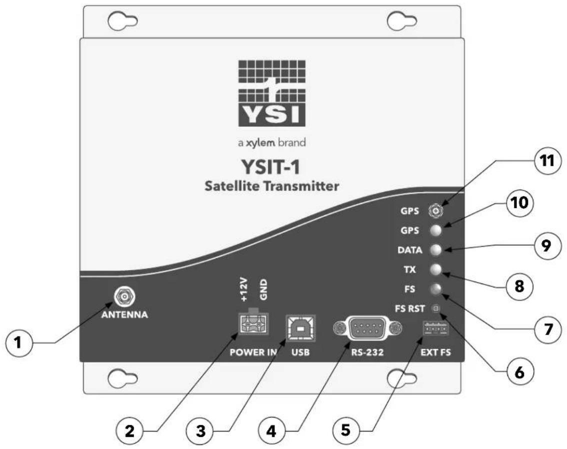
Figure 1 | YSIT-1 Case
Referring to Figure 1, provided below is a list of the major end panel components.
- RF Output Connector
- Main Power Input Connector (+12.5 VDC)
- USB Connector
- RS-232 Serial Port Connector
- External Failsafe Connector
- Failsafe Reset Push-Button
- LED1: Failsafe Tripped LED (Red)
- LED2: RF Transmit Active LED (Green)
- LED4: Data Information LED (Green)
- LED3: GPS Receive Active LED (Green)
- GPS Antenna Connector
2.1 | Connector Information
2.1.1 | Main Power Connections
The main power input to the YSIT-1 is designed for a standard 12 Volt Lead Acid battery. The YSIT-1 uses a 2-position. keyed, locking, high current power connection; Phoenix P/N 1755736. The mating terminal block (Phoenix P/N 1757019) is supplied with the unit.
2.1.2 | RF Output Connections
The RF Output connector (RF OUT) is a standard female SMA RF connector. External cabling must be provided to connect the RF Output to the GOES transmit antenna. For minimal cost, YSI can provide the GOES transmit antenna cable. The standard cable is SMA-to-N with 20' of LMR-240. Custom lengths and antenna connections can also be provided.
2.1.3 | External Failsafe Connections
The External Failsafe Connector is a 4-postion Amphenol P/N 69167-104. The pinout is provided in Table 3. As indicated, the optional external FS LED connects to pins 1 and 2, and the optional external FS reset push-button connects to pins 3 and 4. The mating connector is the Amphenol P/N 78211-004, and can be optionally ordered from YSI. Pin 1 is located nearest to the RS-232 connector.
| Pin Number Signal | |
| 1 LED Anode | |
| 2 Led Cathode | |
| 3 Ext Push-Button Out | |
| 4 Ext Push-Button In |
Table 3 | External Failsafe Pin-out
2.1.4 | GPS Antenna Connections
The GPS Antenna connector (GPS ANT) is a standard female MCX RF connector. The GPS Antenna connection must be interfaced to either a Trimble 3V Bullet (P/N 48360) or a Trimble 3V Magnetic-Mount Patch (39265-50) antenna. If desired YSI can supply either the antenna and/or the interface cable for a Bullet antenna (the Magnetic Mount antenna incorporates a 5M cable). The standard Bullet interface cable is MCX-to-TNC with 20' of LMR-240; custom lengths can also be provided.
2.1.5 | RS-232 Serial Port Connections
The RS-232 Serial Port connector typically provides the host datalogger interface. The connector is a standard 9-pin female Sub-D connector.
Table 4 provides the signal connection for the 9-pin female Sub-D connector. Note that the signal names are referenced to the YSIT-1; e.g. the TXD line is the transmit output from the YSIT-1, which should be connected to the receive input of the host. All signals are true bipolar RS-232 levels.
| Pin Number Signal Description | |
| 1 N/C No Connect | |
| 2 TXD Transmit Data | |
| 3 RXD Receive Data | |
| 4 N/C No Connect | |
| 5 GND Signal Ground | |
| 6 N/C No Connect | |
| 7 RTS Request To Send | |
| 8 CTS Clear To Send | |
| 9 N/C No Connect |
Table 4 | RS-232 Serial Port Pin-out
If desired, the connections shown in Table 4 allow the transmitter to be directly connected to a standard COMM port on a PC using a straight-through 9 conductor RS-232 patch cable.
Use of the RTS and CTS lines are optional as explained in Sections 1.2.3.8.2 and 3.1.
2.1.6 | USB Connector
The USB connector is a standard Type B Device connector. The USB interface will most commonly be used to connect the YSIT-1 to a computer or laptop for configuration, troubleshooting, and/or interrogation of the Event/Parameter log.
The internal circuitry is a USB-to-RS-232 interface. This circuitry is powered by the USB interface, so it does not draw current when not connected to a USB host.
2.2 | Failsafe Reset Push-Button and LED Indicators
Figure 1 also shows the location of the Failsafe Reset Push-Button and LED indicators that are explained in section 1.2.3.11.
2.3 | Power Supply, Battery, and Power Consumption
The following Table is a sample derivation of average power consumption of a YSIT-1 set up to transmit once per hour with a message length of 4 seconds at 300 bps into a UB8 antenna. This power budget does not include the data logger or any external sensor requirements.
| Operating Condition | Milliamps Current at 12.5 Volts | Power Milliwatts | Seconds per Hour | Duty Cycle % | Average Power Milliwatts |
| Sleep 2 25 35 | 86 99.61 24.90 | ||||
| Tx Warm Up 10 | 125 10 0.28 0.35 | ||||
| Transmission 150 | 0 18,750 4 0.11 | 20.63 | |||
| Summary | 3.67 | 3600 | 45.88 |
Table 5 | Sample Power Consumption
For this example, the aggregate average current draw of the YSIT-1 is under 4 milliamps, which equates to a nominal power consumption of under 50 milliwatts. Approximately 45% of the power consumption is related to the actual transmission.
At 300 bps, the data portion of the transmission is approximately 0.8 seconds less than the total transmission time. Further, the number of bytes in the message is this time multiplied by 37.5 bytes per second (300 bits per second/8 bits per byte). As such for this example the approximate number of data bytes in the message is 37.5 × (4 - 0.8) = 120 bytes.
2.4 | Antenna Selections and Mounting
Output power on the YSIT is factory set for the antenna and is an estimated 1 dB cable loss. Typically, the YSIT-1 is configured for one of the antennas listed in Table 6. However, the YSIT-1 can be used with other antennas with gains in the range of 3 to 11 dB. Note that Table 6 applies to NESDIS GOES operation only; contact YSI for information on antenna selection and maximum powers for use on other satellite systems.
To ensure optimum operation, it is necessary to properly aim the transmit antenna. Appendix C provides the necessary azimuth and elevation curves for any Latitude and Longitude within the satellite's look angle.
| Antenna Manufacturer | Model | Gain dB | Max Power 300 GOES (Watts) | Max Power 1200 GOES (Watts) |
| Microcom Design | UB6 (XPress) | 6 | 2.5 | N/A |
| Microcom Design | UB8 | 8 | 1.6 | 5.0 |
| Samco | SAMGOES-11 | 11 | 0.8 | 3.0 |
Table 6 | Antenna Selection for GOES Operation
3. | YSIT-1 Basic Operation and Configuration
Prior to placing the YSIT-1 into service, the unit must be properly configured for the intended application. Configuring the YSIT-1 for operation consists of setting up the data collection functions and/or the transmission parameters.
The YSIT-1 may be configured using the intuitive command line interface using a generic terminal computer application or by the host datalogger. The YSIT-1 can also be easily configured when mated to the Xylem Storm3 datalogger.
Configuration from a terminal interface can be accomplished via the RS-232 port or the USB interface. The USB interface utilizes an internal USB to serial converter and the command set utilized is common to both interfaces. The following sections provide an overview of the terminal interface method. Section 8 provides a complete reference for the serial port command interface.
When the YSIT-1 is mated to a Storm3 datalogger, it is done so via the RS-232 port. While configuration of the transmitter will be handled via the Storm3 (not covered in this manual), the USB interface can still be utilized for diagnostics and testing.
3.1 | Terminal Interface
The YSIT-1 was designed with a highly versatile and intuitive ASCII command line interface, which allows complete configuration via a terminal program, such as HyperTerminal. The interface is also suitable for connection to data loggers equipped with an RS-232 port. By utilizing an ASCII command line interface (as opposed to a menu system), common configurations can be captured in a text editor, which can be edited and easily downloaded to other units to facilitate configuring multiple units with similar setups.
The RS-232 port communicates at 9600 BAUD with 8 data bits, no parity and 1 stop bit. The serial port interface implements the RS-232 standard TXD, RXD, RTS, and CTS signals. While the handshake lines (RTS & CTS) are provided, the YSIT-1 is also designed to work with just the data lines (TXD & RXD). In other words, only the TXD, RXD, and GND connections are absolutely required for proper communications.
As noted above, the USB interface provides an internal USB-to-RS-232 convertor, and the effective serial port also operates at 9600 BAUD with 8 data bits, no parity and 1 stop bit. Unlike the native RS-232 port, the USB interface does not provide any handshaking signals.
With few exceptions, all commands are a three-character alphanumeric abbreviation or acronym of the command functionality. Certain critical commands are more than three alphanumeric characters in length to prevent them from being inadvertently entered. Throughout this manual, the three-character commands are shown in all uppercase and are bolded. Any commands that are longer than three characters are shown in mixed case for readability. In actual use, the YSIT-1 command set is case insensitive, i.e. the YSIT-1 will accept any combination of upper- and lower-case characters for all commands.
Many commands are used to set or retrieve various configuration/calibration parameters. When setting parameters, the command is followed by an equal's sign ('='). When retrieving parameters, the command is issued without any additional characters.
Certain commands are used to direct the transmitter to execute a specific function (e.g. clear a buffer); in such cases, an equal's sign ('=') is typically not permitted. However, some of these commands may allow an optional parameter that further defines what action(s) will be executed. In this case, the equal's sign will be utilized. If the command can be executed, the YSIT-1 will respond with "OK"; otherwise, an error response will be issued.
3.1.1 | Typical Command Usage
Figure 2 shows a typical command line sequence to set up a YSIT-1 for an hourly timed transmission using a terminal interface. Following configuring the YSIT-1 for GOES mode (Satellite=GOES2), the command sequence sets the NOAA/NESDIS supplied parameters, i.e. the DCP's Platform ID, the GOES channel and data rate, the self-timed transmission interval of 1 hour, the start time of the window assignment, and the window length. Following this information, the example in Figure 2 configures some of the user determinable settings, i.e. the message data format (ASCII), and the Timed Operational Flags.
Figure 3 shows a typical response to the Read Configuration (ReadConfiguration) command. The first nine lines of the response essentially parrots the commands that were used to configure Timed operation in the example of Figure 2. The remaining lines show the current configuration for Random transmission operation. Using the Read Configuration command, the user can capture the setup to a text file that can then be edited and downloaded to another YSIT-1.

Figure 2 | Command Line Configuration Example

Figure 3 | Read Configuration Example
3.2 | Enabled versus Disabled Operation
Figure 2 shows a typical command line sequence to set up a YSIT-1 for an hourly timed transmission using a terminal interface. Following configuring the YSIT-1 for GOES mode (Satellite=GOES2), the command sequence sets the NOAA/NESDIS supplied parameters, i.e. the DCP's Platform ID, the GOES channel and data rate, the self-timed transmission interval of 1 hour, the start time of the window assignment, and the window length. Following this information, the example in Figure 2 configures some of the user determinable settings, i.e. the message data format (ASCII), and the Timed Operational Flags.
The YSIT-1 operates in one of two main states, Enabled or Disabled. A Terminal Interface can be used to transition the YSIT-1 back and forth between the Enabled and Disabled state. To deploy a YSIT-1 for operation, it must be placed in the Enabled state.
Upon entering or exiting the Enabled state, the YSIT-1 saves that operational stat in non-volatile memory and will re-enter the same state on power up. As such, if power is lost or a system reset occurs, the transmitter will return to an operational state.
In the Disabled state, the YSIT-1 can be configured. In the Disabled state, the YSIT-1 will not automatically send transmissions. However, test commands have been provided to perform these functions for test and troubleshooting. In the Disabled state, the YSIT-1's Main Microcontroller always remains awake (i.e. does not enter its low power sleep state) and the RS-232 port and USB interface are continuously enabled.
In the Enabled state, the YSIT-1's configuration can NOT be altered. In this state, the unit will transmit normally, i.e. according to the self-timed schedule or send random transmission in response to message data being loaded into the Random Transmit Buffer. When the YSIT-1 is enabled, the unit will also automatically enter the sleep mode to reduce current consumption. To send commands to the YSIT-1, the user or host datalogger must first wake up the unit via the RS-232 port or USB interface before it will respond to any commands.
With the ForceRandom command, the user can send a test transmission when a YSIT-1 is Enabled. Numerous other diagnostic commands can be issued to confirm proper operation without disabling the unit.
3.2.1 | Configuring the YSIT-1 to Power Up Enabled
As previously noted, the YSIT-1 must be Enabled to commence operation. While this can be accomplished in the field by issuing either the Transmitter=Enabled or EnableTx command from a Terminal application or host datalogger, the YSIT-1 also has a Power Up Enable flag that can be used to simplify field deployment.
To configure the YSIT-1 to "Power Up Enabled" using a Terminal interface, the PowerUpEnable=1 command can be used (see Section 8.4.8).
When the Power Up Enable flag is set, the YSIT-1 will automatically enter the Enabled state when power is applied. This will cause the unit to energize the GPS receiver to obtain time sync with UTC. However, neither scheduled internal parameter collection nor any transmissions will occur until the YSIT-1's clock is set using GPS. Once the clock is set, the unit will automatically schedule any parameter collections and the first self-timed transmission and begin normal operation.
As noted above, the YSIT-1 remembers the last operation state (Enabled or Disabled) it was in. This is accomplished by automatically updating and the Power Up Enable flag when the transmitter goes into or out of the Enabled state. Using the PowerUpEnable command allows the user to configure the transmitter prior to heading to the field and not have to Enable the transmitter. By setting the Power Up Enable flag while the unit is Disabled and saving the configuration, the YSIT-1 will come up Enabled.
3.2.2 | GPS Receiver, Time Sync, and TCXO Calibration on Power Up
Regardless of whether the YSIT-1 powers up into the Enabled or Disabled state, the GPS receiver will be automatically energized on startup and a Time Sync and TCXO Calibration will be performed. Once these operations are completed, the GPS receiver will be automatically powered down.
3.3 | GPS Time Sync and TCXO Calibration Settings
The YSIT-1 provides several commands to fine-tune the GPS utilization for the intended application: specifically, the GPS Time Sync and GPS TCXO Calibration options.
First, the user can specify how often, in hours, the GPS receiver is energized to synchronize the YSIT-1's internal clock (GPSSyncRate see Section 8.8.1). The default setting is 24 hours, or once a day.
Second, a command is provided to configure how often the YSIT-1 will calibrate the internal TCXO using the GPS receiver (GPSTCXOCal see Section 8.8.2). The default is once every 10 days, which should be wiladequate for most applications. Note, to maintain the required transmit frequency accuracy for GOES operation, the YSIT-1 MUST perform a TCXO calibration at least once every 20 days. Otherwise, per NOAA/NESDIS requirements, the YSIT-1 will discontinue making transmissions. However, any configured periodic internal parameter collection functions will remain active.
The third parameter that can be configured is a timeout value in minutes (GPSSyncCalTimeout see Section 8.8.3). If the GPS receiver cannot acquire sufficient satellites to perform a Time Sync or TCXO Calibration in the specified time, e.g. 15 minutes, the operation will be aborted and re-scheduled for the next hour. This timeout is simply to minimize current drain on the system battery if some fault exists in the GPS subsystem.
Finally, using the GPSLog command (see Section 8.8.4), the YSIT-1 can be configured to log any occurrence of a GPS Time Sync, or TCXO Calibration in the Event/Parameter buffer. When a Time Sync event is logged, the log entry's timestamp is the actual time the sync occurred, and the data saved is the YSIT-1's clock error just prior to the synchronization; this value is measured and stored in seconds with millisecond resolution. When the YSIT-1 logs a TCXO calibration, the correction factor in parts per million is logged.
The default configuration of the YSIT-1 is to log GPS events.
4. | YSIT-1 Operation with GOES
This section provides an overview of the required setup of the YSIT-1 for operation on the GOES DCS system.
4.1 | GOES DCS Description
A more complete description of the GOES DCS is included on the references in the appendices. The description here is given to aid in the initial operating set up of the YSIT-1.
GOES DCS is a US supported system for the collection of environmental data. Its principal components are the geosynchronous spacecrafts (East and West), NOAA's Wallops Command and Data Acquisition Station (WCDA) located at Wallops Island, and the Remote Data Collection Platform (DCP) transmitters. These elements are shown in the Figure 4.
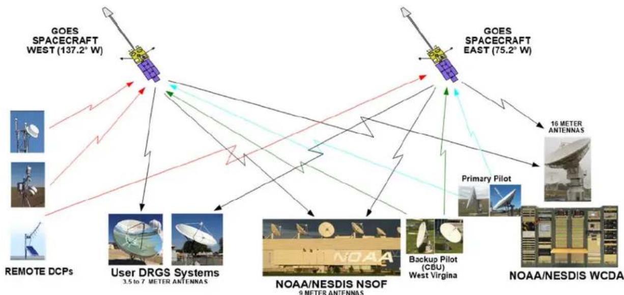
flowchart
graph TD
    A["GOES SPACECRAFT WEST (137.2° W)"] --> B["User DRGS Systems 3.5 to 7 METER ANTENNAS"]
    C["GOES SPACECRAFT EAST (75.2° W)"] --> D["NOAA/NESDIS NSOF 9 METER ANTENNAS"]
    E["Primary Pilot"] --> F["Backup Pilot (CBU) West Virginia"]
    G["REMOTE DCPs"] --> A
    G --> C
    H["NOAA/NESDIS WCDA"] --> I["16 METER ANTENNAS"]
    H --> J["NOAA/NESDIS WCDA"]
Figure 4 | Major Elements of GOES DCS
The spacecrafts are located at approximately 75.2° W (GOES East) and 137°.2 W (GOES West) longitude and zero latitude positions at a geosynchronous altitude of 22,236 miles (35,786 km) above the earth's surface. The remote DCPs transmit in a frequency band of about 402 MHz. The downlink from the spacecraft is at 1680-1695 MHz and includes the DCS signals from the remote sites along other weather data, e.g. earth imagery. The uplink frequencies are reserved internationally for exclusive use in this service.
GOES DCS is part of a worldwide system of satellites that provide global coverage for environmental observations that includes systems such as EUMETSAT/METEOSAT, JMA (Japan) Himawari, and INSAT.
In all these systems, the satellites function as radio repeaters where signals in the specified frequency band are received by the satellite, amplified, converted in frequency and relayed to the ground receiving equipment of the system operator.
The system user provides the remote sensing equipment. Received data or messages may be obtained from the system operator via various terrestrial communication links (e.g. the Internet) and satellite rebroadcasts. However, the system user may also provide their own satellite-receiving equipment, also known as a Direct Readout Ground Station (DRGS), to directly receive the remote transmissions.
Since the satellite repeater is shared by all users, its method of shared use is specified by the system operator. These methods of use and equipment must be agreed to by the system users.
The YSIT-1 is certified for use on:
• GOES, all bands
• METEOSAT International and Regional Bands (certification pending)
• EUMETSAT HRDCP (certification pending)
Currently the only operating method for GOES DCS is self-initiated; interrogation or polled operation is not currently supported. The YSIT-1 supports two methods of self-initiated operation, self-timed and random reporting. The self-timed mode uses the transmitter's internal clock to trigger a data transmission. The random mode typically uses sensor activity to trigger a transmission sequence.
The frequency band of operation for GOES DCS uplink is 401.7 to 402.1 MHz. Per the second certification standard (CS2), the 400 kHz frequency band is divided into 532 channels of 750 Hz each for low-rate operation of 300 bps. Portions of this same frequency band can be allocated to 1200 bps operation; in the latest standard, a 1200 bps channel requires three consecutive 750 Hz channel, or 2,250 Hz. In the original HDR certification standard (CS1), 300 bps channels were 1,500 kHz wide, and 1200 bps channels were 3kHz wide. The allocation of 300 bps channels versus 1200 bps channels is solely at the discretion of NOAA/NESDIS, the GOES system operator. NOAA is currently operating in a transition phase where both CS1 and CS2 transmissions are being made by users' remote DCPs.
The target completion date for the transition period is May 2026. All 300 bps CS1 channels can also support CS2 transmissions to facilitate the transition. As the transition nears completion, NOAA will begin to assign new CS2 only channels, which will essentially double the GOES DCS channel capacity.
NOAA/NESDIS (and other system operators) typically specify or assign the following items to the user:
• List of Certified Transmitters available for selection
- Remote Platform ID of 8 hexadecimal characters
- Operating channel(s)
- Operating data rate(s)
• Self-Timed reporting time slot
• Random reporting daily transmission rate
An example of received messages and their associated NOAA assigned time slots is shown in Figure 5. The yellow lines indicate the actual times of the received messages overlaying the assigned windows as indicated by the two-tone gray spaces. The messages would be ideally located in the center of the assigned time spaces.

line
| 1/2 Hour Segments (MM SE) | Value | | ------------------------- | ----- | | 11.20 | 13.30 | | 11.45 | 13.00 | | 11.70 | 12.20 | | 11.95 | 12.00 | | 12.20 | 11.30 | | 12.45 | 11.00 | | 12.70 | 10.20 | | 13.00 | 10.00 | | 13.30 | 09.30 | | 13.65 | 09.00 | | 14.00 | 08.20 | | 14.35 | 08.00 | | 14.70 | 07.30 | | 15.05 | 07.00 | | 15.40 | 06.30 | | 15.75 | 06.00 | | 16.20 | 08.00 | | 16.55 | 08.20 | | 17.00 | 08.40 | | 17.35 | 08.60 | | 17.70 | 08.80 | | 18.05 | 09.00 | | 18.40 | 09.20 | | 18.75 | 09.40 | | 19.20 | 09.60 | | 19.55 | 09.80 | | 20.00 | 10.00 | | 20.35 | 10.20 | | 20.70 | 10.40 | | 21.05 | 10.60 | | 21.40 | 10.80 | | 21.75 | 11.00 | | 22.20 | 11.20 | | 22.55 | 11.40 | | 23.00 | 11.60 | | 23.35 | 11.80 | | 23.70 | 12.00 | | 24.05 | 12.20 | | 24.40 | 12.40 | | 24.75 | 12.60 | | 25.20 | 12.80 | | 25.55 | 13.00 | | 26.00 | 13.20 | | 26.35 | 13.40 | | 26.70 | 13.60 | | 27.05 | 13.80 | | 27.40 | 14.00 | | 27.75 | 14.20 | | 28.20 | 14.40 | | 28.55 | 14.60 | | 29.00 | 14.80 | | 29.35 | 15.00 | | 29.70 | 15.20 | | 30.05 | 15.40 | | 30.40 | 15.60 | | 30.75 | 15.80 | | 31.20 | 16.00 | | 31.55 | 16.20 | | 32.00 | 16.40 | | 32.35 | 16.60 | | 32.70 | 16.80 | | 33.05 | 17.00 | | 33.40 | 17.20 | | 33.75 | 17.40 | | 34.20 | 17.60 | | 34.55 | 17.80 | | 35.00 | 18.00 | | 35.35 | 18.20 | | 35.70 | 18.40 | | 36.05 | 18.60 | | 36.40 | 18.80 | | 36.75 | 19.00 | | 37.20 | 19.20 | | 37.55 | 19.40 | | 38.00 | 19.60 | | 38.35 | 19.80 | | 38.75 | 20.00 | | 39.20 | 20.20 | | 39.55 | 20.40 | | 40.00 | 20.60 | | 40.35 | 20.80 | | 40.75 | 21.00 | | 41.20 | 21.20 | | 41.55 | 21.40 | | 42.00 | 21.60 | | 42.35 | 21.80 | | 42.75 | 22.00 | | 43.20 | 22.20 | | 43.55 | 22.40 | | 44.00 | 22.60 | | 44.35 | 22.80 | | 44.75 | 23.00 | | 45.20 | 23.20 | | 45.55 | 23.40 | | 46.00 | 23.60 | | 46.35 | 23.80 | | 46.75 | 24.00 | | 47.20 | 24.20 | | 47.55 | 24.40 | | 48.00 | 24.60 | | 48.35 | 24.80 | | 48.75 | 25.00 | | 49.20 | 25.20 | | 49.55 | 25.40 | | 50.00 | 25.60 | | ... | ... |Figure 5 | Channel 49 GOES East Received Messages Overlaid Time Assigned Slots
4.2 | Set Up for Use with Self-Timed Operation
To configure a YSIT-1, the user should have on hand the following information and equipment:
■ NOAA/NESDIS information for:
• Reporting Channel and BAUD/BPS Rate, example is 195 at 300 bps
• Reporting Time, e.g. 02:30 (in UTC/GMT; not local time)
• Reporting Interval, e.g. 60 minutes
• Reporting Window length, e.g. 10 seconds
■ YSIT-1 connected to laptop, power supply, antenna or RF load, and GPS antenna.
Time given by NESDIS is the time after midnight of UTC/GMT on which the first transmission of that day will be made. The YSIT-1's clock must be synchronized to UTC/GMT for proper operation, which will occur automatically when the YSIT-1's internal clock is set using the integral GPS receiver.
The following paragraphs detail the procedures for setting up a YSIT-1 for Self-Timed operation. However, the information provided only covers the scheduling and formatting of self-timed transmissions; the procedures and set up information for loading data into the Timed transmission buffer will be covered in later sections.
Figure 2 provides an example of setting up the YSIT-1 for GOES Self-Timed operation. A minimum of seven commands must be provided to properly schedule and format GOES self-timed transmissions.
Note that all the commands involving transmitter set up require the YSIT-1 to be placed in the Disabled mode (i.e. first send the Transmitter=Disabled or DisableTx command). Complete descriptions of all commands are provided in Section 8.2. Table 7 provides a summary of the commands required to complete the Self-Timed setup.
When a Terminal Interface is used to setup a YSIT-1, it is often helpful to perform a ReadConfiguration command. This command prints out the current configuration and presents that information in the proper format as shown in Figure 3.
| Self-Timed Transmission Configuration Commands | ||
| Command Section Notes | ||
| TimedBPS=bbbb 8.3.2 Self-Timed Data Rate (e.g. 300 or 1200) | ||
| TimedChannel=ccc 8.3.4 Self-Timed Transmit Channel | ||
| TimedTxInterval=hh:mm:ss 8.3.5 Interval in hours, minutes, and seconds | ||
| OffsetTime=hh:mm:ss 8.3.6 First Tx in hours, minutes, and seconds | ||
| TimedWindowLength=xxx 8.3.7 Window in seconds (1 - 110) | ||
| TimedOpFlags=xx | 8.3.8 | Timed Flags - Bit 0 determines window centering |
| TimedDataFormat=xxxxxx | 8.3.9 | ASCII, Pseudo Binary, or Binary Format |
Table 7 | Timed Transmission Setup Commands
4.3 | Set Up for Use with Random Operation
The user should have on hand the following information and equipment:
■ NOAA/NESDIS information for:
• Reporting Channel and BAUD Rate, example is 121 at 300 bps
• Reporting Interval, e.g. 5 minutes
• Reporting Repeat Count, e.g. 3 transmissions
■ YSIT-1 connected to laptop, power supply, antenna or RF load, and GPS antenna.
The following paragraphs detail the procedures for setting up a YSIT-1 for Random operation. However, the information provided only covers the scheduling and formatting of self-timed transmissions; the procedures and set up information for loading data into the Random transmission buffer will be covered in later sections.
Figure 6 provides an example of setting up the YSIT-1 for Random operation using a Terminal interface. A total of seven commands must be provided to properly schedule and format random transmissions.
Note that all the commands involving transmitter set up require the YSIT-1 to be placed in the Disabled mode (i.e. first send the Transmitter=Disabled or DisableTx command). Complete descriptions of all commands are provided in Section 8.2. Table 8 provides a summary of the commands required to complete the Random setup.
| Random Transmission Configuration Commands | ||
| Command Section Notes | ||
| RandomBPS=bbbb 8.3.13 Random Data Rate (e.g. 300 or 1200) | ||
| RandomChannel=ccc,bbbb 8.3.14 Random Transmit Channel | ||
| RandomInterval=mm 8.3.15 Interval in minutes | ||
| RandomPercent=pp 8.3.16 Randomization in percent | ||
| RandomRepeatCnt=xx 8.3.17 | Repeat count | |
| RandomDataFormat=xxxxxxx | 8.3.18 | ASCII, Pseudo Binary, or Binary |
| RandomOpFlags=xx | 8.3.19 | Random Op Flags |
Table 8 | Random Transmission Setup Commands
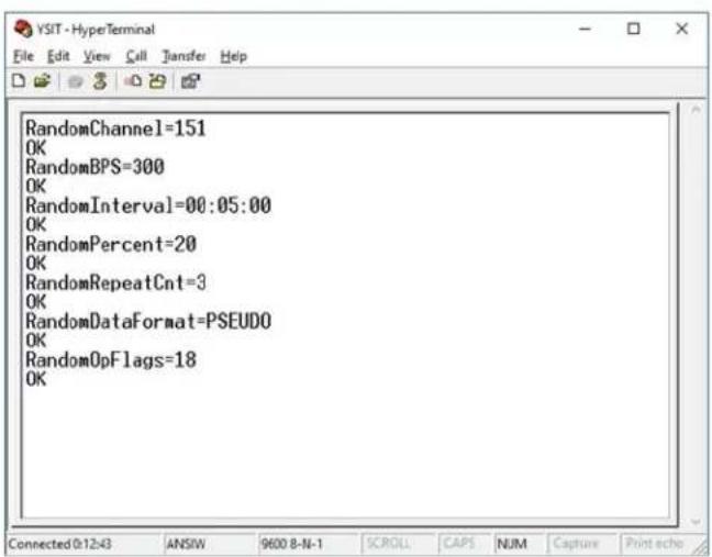
Figure 6 | Random Transmission Terminal Setup
4.4 | Timed and Random Operation Flags
As indicated in Table 7 and Table 8, both Self-Timed and Random transmission setups include a command to configure a set of Op or Operation Flags. Table 9 summarizes all the Op Flags; as indicated, five of the Op Flags are identical to both Timed and Random Operation and will be discussed in tandem in the following subsection. The subsequent subsection will detail the flags unique to Timed transmissions.
| Transmit Operation Flags | |||
| Bit Name Used In Description | tion | ||
| 0 Window Position Timed Only 0 = Message aligned at top of Timed Window.1 = Message aligned to center of Timed Window. | |||
| 1 Buffer Dump Timed & Random 0 = Do not dump Timed/Random Buffer.1 = Dump Timed/Random Buffer to Serial Port after Tx. | |||
| 2 Status Dump Timed & Random 0 = Do not dump Timed/Random status.1 = Dump Timed/Random status to Serial Port after Tx. | |||
| 3 | Log TX Start | Timed & Random | 0 = Do not log start of Tx in Event/Parameter buffer.1 = Log start of Tx in Event/Parameter buffer. |
| 4 | Log TX End | Timed & Random | 0 = Do not log end of Tx in Event/Parameter buffer.1 = Log end of Tx and stats in Event/Parameter buffer. |
| 5 | Dump To USB | Timed & Random | 0 = Dump Buffer/Status to RS-232 port.1 = Dump Buffer/Status to USB Interface. |
| 6 | Buffer Empty | Timed Only | 0 = Send null data if Timed Buffer empty.1 = Send “BUFFER EMPTY” if no Timed data. |
| 7 | No Clear | Timed Only | 0 = Timed Buffer cleared after transmission.1 = Timed Buffer not cleared after transmission. |
Table 9 | Transmit Operation Flags
The operation flags are a bit-mapped value as explained in Section 8.3.8 (TimedOpFlags) and Section 8.3.19 (RandomOpFlags).
4.4.1 | Common Operation Flags
The five common Operation Flags are primarily intended for testing and troubleshooting.
The Dump Buffer and Dump Status flags, when set, direct the YSIT-1 to dump test information to a serial interface when a transmission occurs. Using these flags, the user can configure the YSIT-1 to dump the contents of corresponding transmission buffer and/or the status results (see Section 8.10.9) from the transmission. The buffer dump begins at the start of the transmission, while the status report is sent at the completion of the transmission. The Buffer Dump and Status Dump bits are primarily intended for testing.
The Dump to USB bits determines the destination of the information dump; i.e. either to the RS-232 Serial Port or the USB Port depending on the state of this bit. It is not possible to automatically dump this information to both the Serial Port and the USB Port.
The two "Log" flags, when set, direct the YSIT-1 to log the occurrence and/or results from a transmission in the Event/Parameter log. This information can be retrieved at a later date (see Section 8.12). Logging the Beginning of the Transmission simply logs the time the transmission was started and the type of transmission. Logging the End of the Transmission directs the YSIT-1 to capture when the transmission completed and whether a fault occurred. Recalling this data can provide useful information about the performance of the unit over time.
4.4.2 | Timed Only Operation Flags
Three additional flags applicable to Timed transmissions only are included in the Timed Operation Flags as shown in Table 9.
4.4.2.1 | Center Transmission in Window
The Window Position flag, when set, directs the YSIT-1 to center the Timed transmission within the programmed transmission window. Specifically, prior to sending a Timed message, the YSIT-1 will compute the message length in seconds, subtract this value from the Timed Window Length (TimedWindowLength) setting, and adjust the transmission start time by one half of the difference. This process ensures that the transmission is centered in the window; i.e. equal amounts of unused time on both ends of the self-timed window. Not setting this flag will direct the YSIT-1 to start the message at the top of window.
Centering the transmission in the window ensures the maximum protection from being interfered with by a platform in a neighboring window, especially when the message length is small compared to the window size. This approach can be critical to reliable message reception when neighboring windows are “owned” by another GOES user and is recommended by NOAA/NESDIS.
4.4.2.2 | Timed Buffer Control Flags
The remaining two Timed Operation Flags are related to the Timed message buffer. The Buffer Empty flag directs the YSIT-1 to send the message "BUFFER EMPTY" if the Timed message buffer is empty at the start of a timed transmission, i.e. has not been loaded by the host. The No Clear flag overrides the default operation of automatically clearing the Timed message buffer at completion of a transmission and relieves the host from having to issue the Clear Timed Buffer (ClearTimedBuffer) command after every transmission.
5. | Loading Message Data into Transmit Buffers
While the YSI YSIT-1 is essentially a "transmitter only", it does have the capability to capture key transmission and system parameters. However, the message data for transmissions must be provided by an external host datalogger.
5.1 | USB/RS-232 Message Data from an External Datalogger
As noted above, the YSIT-1 requires that the message data that it will load into a transmission buffer be provided by a datalogger. Further, the datalogger is responsible for capturing and formatting the data before providing it to the YSIT-1. Data for the Timed Buffer is supplied using the Timed Data (TimedData) command, see Section 8.5.2. Data for the Random Buffer is supplied using the Random Data (RandomData) command, see Section 8.5.6.
The TimedData and RandomData commands can be utilized on the RS-232 port, the USB interface, or both. Note that loading data into the Random Buffer is also the event which triggers the Random reporting sequence.
5.2 | Transmission Health Parameters
While the transmission data is provided externally, the YSIT-1 captures key transmission health parameters that the datalogger can include in a message transmission in the form of health parameters. These parameters can also be useful for troubleshooting and diagnostic purposes. The three key transmit health parameters are 1) the battery voltage under load (BattDuringTx, see Section 8.10.10), 2) forward transmit power (LastForwardPower, see Section 8.10.11), and 3) reverse (aka reflected) transmit power (LastReversePower, see Section 8.10.12). The internal temperature at the time of transmission is also captured.
5.3 | Internal Parameters
The YSIT-1 implements functions to capture and log various system/transmit parameters, e.g. internal temperature, battery or supply voltage, RF transmit forward and reflected power, etc. Since these are not environmental sensors, these are referred to as Internal Parameters throughout this manual.
Since the transmit parameters are sampled during a transmission, if the sampled values are to be reported, they must be included in the next transmission.
Serial commands are available to allow the host datalogger to read all these internal parameters for inclusion in a transmitted message.
5.3.1 | Temperature Sensor
While the primary purpose of the internal temperature sensor is to monitor the temperature of the TCXO for improved time keeping accuracy (see Section 1.2.3.1.2), the temperature readings can also be captured for other purposes. While this temperature cannot typically be used for environmental monitoring since the sensor resides inside the YSIT-1, it can provide a useful measurement of the temperature inside an enclosure.
The measurement reading from the temperature sensor has a resolution of 0.25^ . The ASCII format of the temperature reading has a maximum width of 7 characters ( ± xxx.xx): sign, 1-3 digits left, decimal point, 2 digits right.
To read the current temperature of the YSIT-1, the TCXOTemp command (Section 8.6.2.6) is used.
5.3.2 | Battery or Supply Voltage
The battery voltage sensor allows the unit's power source (battery or power supply) to be read in VDC. The voltage reading for this sensor has a resolution of 0.1 VDC. The ASCII format of the battery voltage has a maximum width of 5 characters (±xx.x): sign, 1-2 digits left, decimal point, 1 digit right.
To read the current battery voltage, which is typically not during a transmission and therefore not under maximum load, the ReadBattVolts command (Section 8.6.2.6) is used.
5.3.3 | Internal Parameter Logging
The internal parameters discussed in the previous sections can also be logged into the Event/Parameter. The default configuration for the YSIT-1 is to log the internal temperature and battery voltage on an hourly basis. The default configuration also enables logging of the four transmit health parameters (battery under load, forward power, reverse power, and internal temperature).
Complete details of modifying or setting up the internal parameter logging can be found in Section 8.6.
6. | Formatting Transmission Buffers
As noted in Section 5, the YSIT-1's transmission buffers are expected to be loaded from an external datalogger (e.g. the Xylem Storm3) connected via the RS-232 port and/or the USB interface.
Even though the external datalogger is responsible for formatting the data before providing it via the serial interface(s), the YSIT-1 still needs to know which GOES message format (ASCII or Pseudo Binary, or in the future 8-bit Binary) is being utilized for two reasons.
First, the YSIT-1 must populate or set key bits for the GOES Flag Word based on the message data format since these bits cannot be directly set by the host datalogger.
Second, the GOES certification requirements prohibit certain characters from being transmitted when generating a Pseudo Binary formatted message.
The format for the Timed and Random buffers is selected via the serial interfaces using the TIMedDataFormat (see Section 8.3.9) and RandomDataFormat (see Section 8.3.18) commands, respectively.
6.1 | ASCII Versus Pseudo Binary Formatting
This section provides an instructive brief description of the two types of formats, ASCII versus Pseudo Binary.
When a DCP is configured for ASCII messages, data is sent using the ASCII character set and sensor readings are typically formatted as numeric values in engineering units. ASCII messages quite often label the measurements and utilize various white space characters and delimiters (e.g. spaces, commas, carriage returns, etc.). While this approach provides a message structure that can be easily read upon receipt, it also can significantly increase the message size and duration to the point where the message length may exceed the allotted time window.
While the YSIT-1 supports the ASCII format for platforms that require it, it also supports Pseudo Binary messages. Pseudo Binary formatting can greatly reduce the message size, which allows more data points to be sent than would be possible using ASCII formatted data. Pseudo Binary format is generally preferred by the GOES DCS user community and is strongly recommended by NOAA/NESDIS.
The Pseudo Binary format is an encoding scheme that utilizes a subset of the ASCII character set. Each byte transmitted is an ASCII character and contains 6 bits of binary information. The pseudo binary character set is provided in Table 10 below.
As shown in Table 10, the 64 characters from @ to DEL represent a contiguous range of values from 0 to 63. Apart from DEL (ASCII delete), the characters are all printable. While it is permissible to transmit the DEL character, the pseudo binary specification allows the ? character to be used in place of the DEL so that all the characters are printable.
Using a single pseudo binary character allows one of 64 values to be represented. To represent more values, multiple characters are used. Specifically, two characters can be used to represent a 12-bit value, which yields a range of 0 to 4095 or 4096 distinct values (64*64=4096). If necessary, three and four characters can be used to represent 18-bit and 24-bit values, respectively.
The key to using pseudo binary is range limiting and scaling. For example, it is possible that a single pseudo binary character can be used to represent battery voltage. Since it can be reasonably assumed that the battery voltage in a data collection system will be in the range of 10.0 to 16.3 VDC, a battery voltage reading can be converted to an integer in the range of 0 to 63 by subtracting 10 and multiplying by 10. The resulting integer would then be encoded using the table below. For a battery reading of 12.5 the result is 25 = 10^*(12.5 - 10.0) , in which case the corresponding Pseudo Binary value would be the 'Y' character.
As the battery voltage example shows, range limiting is accomplished by adding or subtracting an offset and scaling is applied to convert the value to an integer to the desired precision. The scale value is also known as the "slope". By choosing the appropriate slope and offset values, most readings can be readily converted to one or two pseudo binary characters. Note that by converting the battery voltage to pseudo binary format, the number of characters required to represent the reading is reduced from a minimum of four (e.g. 12.5) to just one character (e.g. 'Y').
Pseudo Binary Character Set
| Char | Hex | Value | Char | Hex | Value | Char | Hex | Value | Char | Hex | Value | |||
| @ 40 | 0 P 50 | 16' 60 3 | 2 p 70 4 | 8 | ||||||||||
| A 41 | 1 Q 51 | 17 a 61 | 33 q 71 | 49 | ||||||||||
| B 42 | 2 R 52 | 18 b 62 | 34 r | 72 50 | ||||||||||
| C | 43 | 3 | S | 53 | 19 | c | 63 | 35 | s | 73 | 51 | |||
| D 44 | 4 | T 54 20 | d 64 36 | t | 74 | 52 | ||||||||
| E 45 | 5 | U 55 21 | e 65 37 | u 75 53 | ||||||||||
| F 46 | 6 V 56 | 22 f 66 3 | 8 v | 76 54 | ||||||||||
| G 47 | 7 W | 57 23 | g 67 39 | w | 77 55 | |||||||||
| H 48 | 8 | X 58 24 | h 68 40 | x | 78 | 56 | ||||||||
| I 49 | 9 Y 59 2 | 5 i 69 4 | 1 y | 79 57 | ||||||||||
| J | 4A | 10 | Z | 5A | 26 | j | 6A | 42 | z | 7A | 58 | |||
| K | 4B | 11 | [ | 5B | 27 | k | 6B | 43 | { | 7B | 59 | |||
| L | 4C | 12 | \ | 5C | 28 | l | 6C | 44 | | | 7C | 60 | |||
| M | 4D | 13 | ] | 5D | 29 | m | 6D | 45 | } | 7D | 61 | |||
| N 4E | 14 ^ 5E | 30 n 6E | 46 ~ 7E | 62 | ||||||||||
| O | 4F | 15 | _ | 5F | 31 | o | 6F | 47 | DEL | 7F | 63 | |||
| ? | 3F | 63 |
Table 10 | Pseudo Binary Character Set
Values that can be both positive and negative can be handled in one of two ways: 1) an offset can be added to shift the range of numbers to all positive values, or 2) the data can be converted to a two's-complement value. Two's-complement representation is a method of expressing negative numbers so subtraction may be performed by a simple fixed-precision binary accumulator (adder). The negative value is computed by complementing each bit and then adding 1. For example, the value 5 is represented in 6-bits as 000101, while the value of -5 is represented as 111011 (111010+000001). Note that most computers represent negative integers in two's-complement format. An alternative method of determining the two's-complement representation is to subtract the value from the 2N, where N is the number of bits to be used. For example, 26 - 5 = 64 - 5 = 59 = 111011 .
A good example of a signed parameter is temperature. To represent a temperature range of -40^ to +60^ to 0.1^ requires 1000 unique values (10*100), which can be easily accomplished with two pseudo binary characters using a slope of 10 and an offset of 40. The offset value ensures all the readings are positive and is an example of the first approach to handling negative values. However, if an offset value of zero is used, the data will have to be represented in two's-complement format.
Using an offset of +40 allows the expected range of values (-40 °C to +60 °C) to be expressed in a unipolar format from 0 to 1000 using two pseudo binary characters. For example, a temperature reading of -10 °C would be represented by the pseudo binary character string 'DI'. Table 10 can be used to convert this representation back to engineering units; note that since the first pseudo binary character represents the upper 6-bits of the 12-bit value, the equivalent value of this character from Table 10 must be multiplied by 64. Specifically, the string 'DI' is equivalent to (4*64)+44 = 300 (i.e. D=4 and I=44). Applying the inverse scaling and offset yields (300/10)-40 = -10.
7. | Retrieving the Event/Parameter Buffer
As has been previously discussed, the YSIT-1 can log system events and internally captured parameters in nonvolatile memory. The log is stored in a circular buffer with each entry in the log time and date stamped. Please refer to Section 1.2.3.2.2 for additional information on the characteristics and capacity of the Event/Parameter log. Also, refer to Sections 3.3, 4.4, 8.6.2, 8.3.8, 8.3.19, and 8.8.4 for information on configuring the types of events and parameters to log.
This section details the procedures to retrieve Event/Parameter log.
7.1 | Events Summary
The capturing of some system Events is user configurable, while other Events are unconditionally captured. In addition to simply being able to monitor when critical YSIT-1 functions occurred, logged Events can be useful troubleshooting tools. For example, checking the Event/Parameter log for transmission results can determine if a missed message was a result of a unit failure, a low battery, or an RF interference.
Table 11 summarizes the Events that may appear in the Event/Parameter log. In addition to the Event Type and Log Code, this table summarizes the data logged for the event and whether the user can configure the Event for capture.
The "STX" and "ETX" Events are tied to transmissions. The "STX" Event simply logs the type of transmission and reports it as an ASCII string. Test transmissions are always logged, while Timed and Random transmissions can be selectively logged. The "ETX" logs the result of the transmission. For good transmission, the data field is simply reported as "NO FAULT". For failed transmissions, a failure code string is reported (see Section 8.10.9 for the possible types of failures).
Two types of GPS related events can be logged (i.e. "SYNC" or "TCXO"). The "SYNC" event identifies when the YSIT-1's internal clock was last synchronized using the GPS receiver; the data captured for this event is the number of seconds the internal clock differed from UTC prior to the synchronization; the value is reported with a resolution of one millisecond. The "TCXO" Event marks when the unit's oscillators were re-calibrated using the GPS receiver and log the absolute error from the expected nominal in parts per million.
The next sequence of Events listed in Table 11 refers to when the YSIT-1 itself is enabled or disabled, and when Self Timed and/or Random transmissions are enabled or disabled. For each of these Events, the data reported is an ASCII string describing the Event.
| Logged Events Summary | |||
| Event Type Log Code Data User Config | |||
| Start of Tx - Test STX "TEST" No | |||
| Start of Tx - Timed STX "TIMED" Yes | |||
| Start of Tx - Random STX "RANDOM" Yes | |||
| End of Tx - Good | ETX | "NO FAULT" platform | Yes |
| End of Tx - Bad | ETX | Failure Code - See Section 8.10.9 | Yes |
| GPS Time Sync | SYNC | Clock Error Prior to Sync in Seconds | Yes |
| GPS TCXO Calibration | TCXO | TCXO Frequency Error in ppm | Yes |
| YSIT-1 Disabled | YSIT-1 | "DIS" | No |
| YSIT-1 Enabled | YSIT-1 | "ENB" | No |
| YSIT-1 Enabled - Logger | YSIT-1 | "ENB LGR" | No |
| Timed Tx Disabled | YSIT-1 | "DIS ST-TX" | No |
| Timed Tx Enabled | YSIT-1 | "ENB ST-TX" | No |
| Random Tx Disabled | YSIT-1 | "DIS RN-TX" No | |
| Random Tx Enabled | YSIT-1 | "ENB RN-TX" | No |
Table 11 | Logged Events Summary
7.2 | EventLog Retrieval
The EventLog command is used to retrieve logged Events and Parameters. This command dumps the most recent 100 entries in the log, assuming there are more than 100 entries in the log. Figure 7 below shows an example of an EventLog dump with fewer than 100 entries in the log.

Figure 7 | EventLog Dump Example
To better see how many entries are stored in the Event/Parameter, the EventLog? command can be used.
When the question mark ('?') is appended to the EventLog command, the YSIT-1 will dump the log entries with a five-digit record number included. The record numbers correspond to the position of the record in the log with the oldest record being 00001. Since the Event/Parameter log is circular, the record numbers are not static, i.e. when the oldest entry is overwritten, the next record in the log becomes number 00001.
Figure 8 shows the same dump as in Figure 7, but with the record numbers included. Note that at the end of the dump, the YSIT-1 also reports the total number of entries in the log, and the number of records reported.

Figure 8 | EventLog? Dump Example
Figure 9 shows an EventLog? dump when there are more than 100 entries in the Event/Parameter log. In this example, there are a total of 123 entries in the log, but only the most recent 100 are reported.
To dump the entire log, the commands EventLogAll and EventLogAll? are used (see Section 8.12.2). When using these commands, the user has the option of filtering the log dump to report just a particular set of records; filtering can be done by date/time, entry type, and/or specific parameter(s) (see Section 8.12.3).
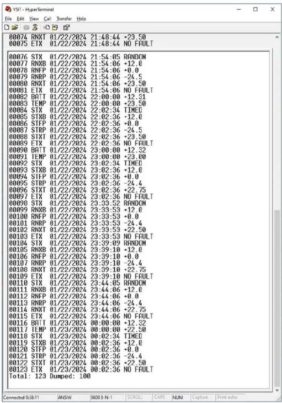
Figure 9 | EventLog? Dump with More Than 100 Entries in the Log
8. | Serial Command Reference
All transmission configuration, system setup, calibration, and diagnostic functions are performed using either the RS-232 port and/or USB interface. Since the USB interface acts as a serial port, both communication paths use the same serial command set.
The YSI YSIT-1 Utility application provides a Graphical User Interface (GUI) to reduce the complexity of configuring, monitoring, and deploying the YSI YSIT-1 by encapsulating the commands detailed in this section since the YSIT-1 is intended to interface to a datalogger to complete the Data Collection Platform. The information provided in this section is critical to completing the datalogger-to-YSIT-1 connection and will also be useful to users that prefer to use just a terminal application to configure the YSIT-1.
8.1 | Serial Command Protocol
The serial protocol utilizes ASCII character command line interface allowing configuration via a terminal program, such as HyperTerminal. This interface is also suitable for connection to data loggers equipped with an RS-232 port. By utilizing an ASCII command line interface (as opposed to a menu system), common configurations can be captured in a text editor and are readily downloadable. This approach also readily supports the loading of the transmit buffers by the datalogger.
8.1.1 | General Characteristics of the Serial Interface Protocol
A [CR] (0x0d) character must be entered first to get the transmitter's attention and is used to terminate a command line. The transmitter responds with "OK" to indicate that it is ready to receive a command. If the transmitter is enabled for transmissions and no command is entered for a period of time (default is 5 seconds, see Section 8.2.1), the transmitter's attention is lost and another [CR] must be entered. Commands can optionally be terminated with [CR][LF]; in other words, a [LF] character received following a [CR] will be ignored.
Each character entered is echoed to the host to allow for simple error checking and to support the terminal nature of the implementation. A backspace character ([BS], 0x08) deletes the last character entered. The ESC character (0x1b) will delete or cancel the entire command.
For commands that dump a significant amount of data, sending the ESC character (or pressing the ESC key when using a Terminal application) will immediately terminate the dump and cause the prompt character to be reported.
8.1.2 | RS-232 Port Hardware Interface
The settings for the RS-232 port are 9600 BAUD, 8 data bits, no parity and 1 stop bit.
The serial port interface implements the RS-232 standard TXD, RXD, RTS, and CTS signals.
To conserve power during operation, the YSIT-1 will enter a sleep mode during idle periods. While the unit is in the low power mode, it monitors the RS-232 input lines and wakes up upon RTS going active or in response to a [CR] being received. If the unit is woken up due to the RTS line becoming active, it will activate the CTS line to signal that it is ready to receive data. If the unit is woken up due to the receipt of a [CR], CTS will be asserted, and the transmitter will respond with "OK".
8.1.3 | USB Hardware Interface
The USB interface utilizes a standard Type B device connection. Internal to the YSIT-1 is a USB-to-Serial converter that translates the USB interface to serial port operation. Like the RS-232 port, the USB serial port settings must be configured for 9600 BAUD, 8 data bits, no parity and 1 stop bit. Unlike the RS-232 port, the USB interface does not provide the RTS and CTS handshake signal.
To minimize the YSIT-1's power consumption and since the USB interface provides a separate power source, the internal USB-to-serial convertor is powered from the USB and not the YSIT-1. While the USB interface is always powered up when connected to a USB host, a [CR] must still be sent and received to wake the YSIT-1 up when it is in its sleep mode, which will result in the transmitter issuing the "OK" string.
8.1.4 | Serial Command Format
All commands use a verbose ASCII string. The commands described in the following sections will include a functional description name with the verbose command string provided parenthetically. Note that while the commands are shown in mixed case for clarity, the YSIT-1 will accept any combination of upper- and lower-case characters for all commands; e.g. Time, TIME, or time yield the same result.
Many commands are used to set or retrieve various configuration/calibration parameters. When setting parameters, the command is followed by an equal's sign ('='). When retrieving parameters, the command is issued without any additional characters.
Certain commands are used to direct the transmitter to execute a specific function (e.g. clear a buffer); in such cases, an equal's sign ('=') is typically not permitted. However, some of these commands may allow an optional parameter that further defines what action(s) will be executed. In this case, the equal's sign will be utilized. If the command can be executed, the YSIT-1 will respond with "OK"; otherwise, an error response will be issued.
Unless otherwise noted, the transmitter will respond to all commands with ...
OK[CR][LF] if the command (and parameter) is (are) accepted.
ERR[CR][LF] if a command or parameter is invalid, or if the command cannot be accepted.
[CR][LF] when returning data parameters.
8.1.5 | Verbose Serial Error Responses
While the default configuration is to just issue ERR in response to an error in a received command, the user can enable more verbose serial responses that provide additional details as to the nature of the error using the DisVerboseErrors command (see Section 8.2.2).
The format of the verbose error responses is ERR:xx(message) [CR][LF]; where xx is a 2-digit ASCII error code and message is a short context sensitive description of the error. The numerical error code facilitates machine-to-machine error reporting without parsing the message field. The descriptive error provides direct user assistance on the error.
A summary of the verbose error responses is provided in Table 12.
| Verbose Error Response | |
| Error Code Message/Description | |
| 01 undefined command | |
| 02 invalid argument | |
| 03 message varies - invalid state | |
| 04 not currently used - reserved | |
| 05 too much data for xxxxxx buffer xxxxxx = timed or random | |
| 06 not currently used - reserved | |
| 07 not currently used - reserved | |
| 08 stored config invalid | |
| 09 internal malfunction | |
| 10 not currently used - reserved | |
| 11 message varies - cannot enable YSIT-1 | |
| 12 aborting data entry |
Table 12 | Verbose Error Response
8.1.6 | Serial Access Rights
All commands are subject to an access right based on either the current state of the transmitter (enabled or disabled for transmissions) or a password protection. Four levels of access rights are currently implemented. These are summarized below and ordered from highest access required to the lowest required access rights.
- Development Access [dev]: Commands used for program debugging and/or certification.
- Factory Access [fct]: Commands used for factory calibration and configuration.
- Transmitter Disabled [dtx]: Commands used for operational configuration by end user.
- Unrestricted [all]: Commands that may be issued at any time; typically, status requests.
Development and Factory access commands are not intended for general use. As such, they are not covered in this document, and are password protected to prevent unauthorized use. Unauthorized use of these commands may cause the YSIT-1 to function incorrectly and could violate NOAA/NESDIS GOES or another satellite operator's certification.
Transmitter Disabled access commands are typically used for configuring the transmitter for GOES operation and are controlled by the state of the transmitter. Commands to change/set these parameters are only allowed when the transmitter is disabled, i.e. transmissions are disabled. If the transmitter is enabled, then only the query form of the command is allowed.
The access level for each command is provided in brackets in the section title using the codes shown in the list above.
8.1.7 | Password Protection for Configuration Commands
In addition to having an access level of [dtx], commands that affect the YSIT-1's configuration setup (e.g. transmissions, message formatting, etc.) can also be password protected to prevent unauthorized access, which is especially useful in a remote access (e.g. modem) situation. The configuration password can be set and/or edited by the ConfigPassword command (see Section 8.9.7).
Once a YSIT-1 has been enabled for operation, changing the configuration requires the user to place the unit in the disabled state using the DisableTx command, followed by entering the password using the CPE command (see Section 8.9.6). Until the configuration is "unlocked" by entering the correct password, the configuration cannot be edited or modified, and an error response (ERR) will be returned to any configuration command. The YSI YSIT-1 Configuration Utility also supports the use of password protection for the configuration.
If the password is not entered or explicitly cleared then it is not necessary to utilize the CPE command to unlock the configuration. However, disabling the YSIT-1 is always required.
Further, note that the password protection does not take effect until the unit has been enabled at least once. As such, entering the password does not immediately lock the configuration to facilitate initial field deployment.
If the configuration password is entered incorrectly or is otherwise unknown to the user (e.g. forgotten), then it is still possible to "unlock" the YSIT-1. However, to do so requires recycling the power and not entering the enabled state. As such, the Power Up Enable (PowerUpEnable) and Configuration Save (ConfigSave) commands (see Sections 8.4.8 and 8.9.1, respectively), are the only configuration commands that are not password protected. Therefore, to unlock a YSIT-1 without knowing the password requires the following 5 step process:
-
Disable the YSIT-1 (DisableTx).
-
Disable power up enables (PowerUpEnable=0).
-
Save the configuration (ConfigSave) - only updates the PowerUpEnable flag, since all other configuration commands are protected.
-
Turn the YSIT-1 off; requires physically disconnecting power.
-
Turn the YSIT-1 on; reconnect power. The YSIT-1 will power up in the disabled state and will not require password unlocking.
Note that the approach outlined above requires the user to be physically present at the YSIT-1 and is not possible to accomplish remotely. Further, this approach avoids the use of a permanent "hidden" or "backdoor" password being hard coded in the YSIT-1 firmware; which once known could be used to unlock any YSIT-1.
8.2 | Serial Port Configuration Commands
The following commands tailor how the RS-232 port or USB serial interface operate. In all cases, the commands are specific to the serial interface the command is issued to; i.e. it is not possible to tailor the operation of the RS-232 port from the USB interface, and vice versa.
However, since these settings are independent, it allows each serial communication path to be optimized for its intended use. For example, the RS-232 serial port will most likely be connected to a datalogger and disable character echo. Verbose error responses might provide the best interface approach. On the other hand, the USB interface will most likely be used by a user interface application where enabling the character echo works best and the verbose error responses are advantageous.
8.2.1 | Disable Echo (DisableEcho=b) [dtx]
The default operation of the RS-232 port and USB serial interface is to echo the characters/bytes when they are received. The Disable Echo command can be used to have the YSIT-1 not echo received data, but instead simply respond after the entire command is received.
Issuing the command DisableEcho=1 disables the echo function on the serial interface the command was received on. Issuing DisableEcho=0 will reenable the echo functionality and is the default setting.
8.2.2 | Disable Echo RS-232 (DisableEchoRS232=b) [dtx]
While the DisableEcho command enables or disables character echoing for the port the command is issued on, the DisableEchoRS232 command can be utilized to specifically enable or disable the echo mode on the RS-232 interface.
Issuing the command DisableEchoRS232=1 disables the echo function on the RS-232 serial interface. Issuing DisableEchoRS232=0 will reenable the echo functionality on the RS-232 serial interface, and is the default setting.
8.2.3 | Disable Echo USB (DisableEchoUSB) [dtx]
While the DisableEcho command enables or disables character echoing for the port the command is issued on, the DisableEchoUSB command can be utilized to specifically enable or disable the echo mode on the USB interface.
Issuing the command DisableEchoUSB = 1 disables the echo function on the USB serial interface. Issuing DisableEchoUSB will reenable the echo functionality on the USB serial interface, and is the default setting.
8.2.4. | Disable Verbose Errors (DisVerboseErrors=b) [dtx]
In the default configuration, the YSIT-1 will simply issue the ERR response whenever an error is detected in the command/argument received, or if the command cannot be executed for some reason; for example, when the YSIT-1 is enabled and a command attempts to change a transmit configuration parameter.
Issuing the command DisVerboseErrors=1 disables verbose error responses on the serial interface the command was received on, and is the default configuration. Issuing DisVerboseErrors=0 will enable verbose error responses.
Table 12 in Section 8.1.5 summarizes the verbose error responses.
8.2.5. | Command Active Time (CommActiveTime=xxx) [all]
This command sets the time the serial communications interface will remain active following RS-232 port or USB interface communications activity. The default comm activity timeout is 5 seconds, but this timeout can be temporarily overridden using the CommActiveTime command. The timeout value can be set from 2 to 255 seconds.
Note that this function only applies when the transmitter has been enabled. During configuration and setup, when the transmitter is disabled, the serial communications interface is always active and will never timeout. Further, the new timeout value is temporary, and will be automatically reset to 5 seconds when the YSIT goes to sleep and wakes back up.
The primary purpose of this command is for a user interface when operating from a terminal program (e.g. for test purposes) and manually entering commands. While the user can press the Enter key to issue a [CR] to wake the YSIT up, it may desirable to set a higher value (e.g. 30-60 seconds) to avoid having to regularly request the transmitter's attention in this manner.
Once the user is done interrogating or checking out the YSIT, this command should then be re-issued with a lower value to simply allow the transmitter to enter sleep mode faster. Note that since the timeout value is automatically reset to 5 seconds when going to sleep and waking backup, the user does not have to worry about forgetting to re-issue the CommActiveTime command and the YSIT drawing excessive current consumption due to extended awake periods.
8.2.6. | Sleep Mode (Sleep) [all]
This command causes the transmitter immediately zero out the RS-232 serial port's or USB interface's activity timer. After transmitting commands or data, the host may issue the Sleep command to speed up the YSIT-1 entering the sleep mode to save battery power. Note that this command just expires the activity timer for the port the command was issued on. If here are other functions being performed or other activity timers still active, the transmitter will not immediately enter the sleep mode.
The response to this command is always OK.
8.3 | Satellite Transmission Configuration Commands
The commands detailed in this section are used to set the configuration parameters for transmissions. Unless otherwise specified, these parameters have invalid default values and must be explicitly set before transmissions can be enabled using the Enable YSIT-1 (EnableTx) command. These parameters are stored in nonvolatile memory by issuing the Configuration Save (ConfigSave) command (see Section 8.9.1) or will be automatically saved when the transmitter is enabled.
The transmitter must be explicitly disabled using the DisableTx command before these parameters can be modified. Parameters can be read by issuing just the command string while transmissions are enabled or disabled. Many of the most commonly used parameters can be read at the same time using the Read Configuration (ReadConfiguration) command.
8.3.1 | Platform ID (PlatformID=xxxxxxxxx) [dtx]
This command sets the Platform ID (i.e. the NOAA/NESDIS GOES or EUMETSAT DCP ID/address) to value xxxxxxxx. Valid range is 0x00000000 to 0xFFFFFFF (4-byte, 8 hexadecimal characters).
8.3.2 | YSIT-1 Satellite Mode (Satellite=xxxxx) [dtx]
The satellite mode command specifies the allowed transmitter modulation and data rate, and the satellite system channel designations. Valid strings for setting the satellite operating mode are provided in Table 13. When setting this parameter, the first letter can be utilized in place of the whole string, but when querying the setting the full string will always be returned.
| Satellite Mode Designations | |||
| Operational Mode Sat | String Mode Notes Data Rates | ||
| NOAA GOES CS2 GOES2 Default - Channels per Version 2 Spec 300,1200 | |||
| METEOSAT/EUMETSAT ME | ETEOSAT | METEOSAT 2ND Generation Channels and EUMETSAT HRDCP Channels | 100,1200 |
Table 13 | Satellite Mode Designations
8.3.3 | Timed Transmit Data Rate (TimedBPS=bbbb) [dtx]
This command sets the bit rate (bbbb) for timed transmissions. The allowable bit rate (bbbb) parameters depend on the YSIT-1 Operation Mode and satellite system being used, and are specified in Table 13.
8.3.4 | Timed Transmit Channel (TimedChannel=ccc) [dtx]
This command sets the channel number (ccc) for timed transmissions. The allowable channel number (ccc) depends on the YSIT-1 Operation Mode and the data/bit rate. The channel number and data rate to utilize must be provided to the user by the system owner.
The channel number must be valid for the data rate specified. Note that if the operation or satellite mode and/or the data/bit rate is altered after setting the channel, the designated channel number may become invalid.
Setting the channel number to 0 will disable timed transmissions when disabling timed transmissions.
Valid channel numbers based on data rate and the satellite system are provided in the table below, but it should be emphasized that not all of these channels may be active or currently in use by the system owner. Note that 0 is always a valid entry.
| Valid Channel Designations | ||
| Operational Mode DataRate | Allowable Channels | |
| NOAA GOES CS2 300 1 thru | 266 and 301 thru | 566 |
| NOAA GOES CS2 1200 3, 6, | 9 ... 265 and 301 | 1, 304, 307 ... 565 |
| METEOSAT/EUMETSAT 100 I01 | thru I11, M1 thru | M33, and M67-M223 |
| METEOSAT/EUMETSAT 1200 E | 001 thru E289 | |
Table 14 | Valid Channel Designations
8.3.5 | Timed Transmit Interval (TimedTxInterval=hh:mm:ss) [dtx]
This command sets the interval between timed transmissions to that hours, minutes, seconds specified in hh:mm:ss. The value range is 00:02:00 to 23:59:59.
The default value is 01:00:00, or once an hour.
8.3.6 | First Transmission Time (OffsetTime=hh:mm:ss) [dtx]
This command sets the time for the first timed transmission of the day. While the TimedTxInterval command sets the interval of the transmissions, the OffsetTime command essentially sets where in the interval the transmission will occur. The valid range is 00:00:00 to 23:59:59.
The default value is 00:00:00.
8.3.7 | Timed Window Length (TimedWindowLength=xxx) [dtx]
This command sets the length of the timed transmit window. Length is specified in seconds. The valid range is 1 to 110 seconds. Note that the maximum window length can exceed the failsafe limits.
The default value is 10 seconds.
8.3.8 | Timed Operation Flags (TimedOpFlags=xx) [dtx]
This command sets the option byte for timed transmissions. The timed option byte is a bit-mapped value that determines various operation modes for timed transmissions. The value must be entered in a hexadecimal format.
The default value for the Timed Operation Flags is 19 in hexadecimal (bits 0, 3 and 4 set to one, and the remaining bits cleared or zero). This default setting enables window centering and logging of the start and end of Timed transmissions.
The bit mapping is provided in the table below; unused bits should be set to 0.
| Timed Operation Flag Byte | ||
| Bit Name Description | ||
| 0 Window Position 0 = Message aligned at top of Timed Window.1 = Message aligned to center of Timed Window. | ||
| 1 Buffer Dump 0 = Do not dump Timed Buffer.1 = Dump Timed Buffer to Serial Port after Tx. | ||
| 2 Status Dump 0 = Do not dump Timed status.1 = Dump Timed status to Serial Port after Tx. | ||
| 3 | Log TX Start | 0 = Do not log start of Timed Tx in Event/Parameter buffer.1 = Log start of Timed Tx in Event/Parameter buffer. |
| 4 | Log TX End | 0 = Do not log end of Timed Tx in Event/Parameter buffer.1 = Log end of Timed Tx and stats in Event/Parameter buffer. |
| 5 | Dump To USB | 0 = Dump Timed Buffer/Status to RS-232 port.1 = Dump Timed Buffer/Status to USB Interface. |
| 6 | Buffer Empty | 0 = Send null data if Timed Buffer empty.1 = Send “BUFFER EMPTY” if no Timed data. |
| 7 | No Clear | 0 = Timed Buffer cleared after transmission.1 = Timed Buffer not cleared after transmission. |
Table 15 | Timed Operation Flag Byte
The Buffer Dump and Status Dump bits are primarily intended for test and direct the YSIT-1 to automatically dump the information whenever a self-timed transmission occurs to either the RS-232 Serial Port or the USB Port depending on the state of the Dump To USB bit. It is not possible to automatically dump this information to both the Serial Port and the USB Port.
8.3.9 | Self-Timed Message Alignment (TimedWindowAlign) [dtx]
This command allows setting of the alignment of Timed Transmissions in the assigned window independent of any other Timed Operation Flags (Section 8.3.8). The options are CENTER and TOP. NOAA highly recommends window centering.
8.3.10 | Self-Timed Empty Buffer Mode (TimedEmptyBufferMode) [dtx]
This command allows the setting of an empty self-timed buffer to be processed independent of any other Timed Operation Flags (Section 8.3.8). Regardless of whether Timed data has been provided by the host or not, the YSIT-1 will always send a scheduled Timed transmission. Options are NULLS (i.e. message sent without any data, just the Platform ID and any system required information), and MSG (i.e. the "BUFFER EMPTY" message will be sent in the data field of the transmission).
For partial backward compatibility to the Xylem H-2221-V2 transmitter, the YSIT-1 will also accept the setting of NOTX, and respond with OK. However, the YSIT-1 does not actually implement the functionality of not sending a Self Timed transmission when the Timed Data Buffer is empty. As such, when this option is entered, the YSIT-1 will configure itself for the MSG option.
8.3.11 | Self-Timed Buffer Mode (TimedBufferMode) [dtx]
This command allows how the Timed buffer is handled after a scheduled transmission is made independent of any other Timed. Options are CLEAR (i.e. the Timed buffer will be automatically cleared upon completion of the self-timed transmission), and KEEP (i.e. the Timed buffer will not be automatically cleared).
8.3.12 | Timed Data Format (TimedDataFormat=xxxxxx) [dtx]
This command sets the timed transmission data format to ASCII, Pseudo (pseudo binary), or Binary (a.k.a. A, P, or B).
Currently Binary transmissions are not supported on the GOES DCS, but this option has been included for use once NOAA releases a Binary Protocol.
The default value is ASCII.
8.3.13 | Random Transmit Data Rate (RandomBPS=bbbb) [dtx]
This command sets the bit rate (bbbb) for random transmissions. The allowable bit rate (bbbb) parameters depend on the YSIT-1 Operation Mode and satellite system being used, and are specified in Table 13.
8.3.14 | Random Transmit Channel (RandomChannel=ccc[,bbbb]) [dtx]
This command sets the channel number (ccc) for random transmissions. The allowable channel number (ccc) depends on the YSIT-1 Operation Mode and the data/bit rate. The channel number and data rate to utilize must be provided to the user by the system owner.
The channel number must be valid for the data rate specified. The data rate must be valid for the satellite system or YSIT-1 Operation Mode being used. Note that if the operation or satellite mode and/or the data/bit rate is altered after setting the channel, the designated channel number may become invalid.
Setting the channel number to 0 will disable random transmissions; when disabling random transmissions, the bit rate parameter is not required.
Valid channel numbers based on data rate and the satellite system are provided in Table 14, but it should be emphasized that not all of these channels may be active or currently in use by the system owner. Note that 0 is always a valid entry.
8.3.15 | Random Transmit Interval (RandomInterval=xxx) [dtx]
This command sets the random transmission interval. The randomizing interval is the interval in which a random transmission will occur once a random report has been triggered. The actual transmission time will be random, but on average it will occur at this rate.
For GOES operation, xxx is in minutes, and the valid range is 5 to 99 minutes.
The default value is 5 minutes.
8.3.16 | Randomization Percent (RandomPercent=pp) [dtx]
This command sets the random transmission randomizing percentage. This value determines the range of randomization as a percentage of the Random Interval (RandomInterval). Random transmissions will occur at a uniformly distributed random time within this range and on average occur at the Random Interval rate. The valid range is 10 to 50%.
The default value is 20%
For example, for a Random Interval of 5 minutes and a Random Percent of 20%, then the time between any two random transmissions will be 4 to 6 minutes ( 5 ± 1 minutes).
8.3.17 | Random Repeat Count (RandomRepeatCnt=xx) [dtx]
This command sets the random transmission repeat count. The random transmission repeat count is the number of times a random transmission will be sent before the sequence of Random reports is terminated. Random transmissions will occur once every random transmission interval as specified by the Random Interval (RandomInterval) parameter. The valid range of this parameter is 0 - 99.
For example, a value of 3 will direct the transmitter to send the data in the Random buffer 3 times before terminating.
A value of 0 indicates that random transmissions will occur every random transmission interval until explicitly terminated by the host.
Random reports are only triggered in response to data being loaded into the buffer via the RandomData command. Upon completion of the programmed number of random transmissions, the Random buffer will be automatically cleared, and the random transmission sequence terminated. When RandomRepeatCnt=0, random transmissions will continue until the host clears the Random buffer.
The default value is 3.
8.3.18 | Random Data Format (RandomDataFormat=xxxxxx) [dtx]
This command sets the random transmission data format to ASCII, Pseudo (pseudo binary), or Binary (a.k.a. A, P, or B).
Currently Binary transmissions are not supported on the GOES DCS, but this option has been included for use once NOAA releases a Binary Protocol.
The default value is Pseudo.
8.3.19 | Random Operation Flags (RandomOpFlags=xx) [dtx]
This command sets the option byte for random transmissions. The random option byte is a bit-mapped value that determines various operation modes for random transmissions. The value must be entered in a hexadecimal format.
The default value for the RandomOpFlags is all bits cleared, i.e. 00 hexadecimal.
The default value for the Random Operation Flags is 18 in hexadecimal (bits 3 and 4 set to one, and the remaining bits cleared or zero). This default setting enables logging of the start and end of Random transmissions.
The bit mapping is provided in the table below; unused bits should be set to 0.
| Random Operation Flag Byte | ||
| Bit Name | Description | |
| 0 Not used | Reserved for future use (set to 0) | |
| 1 Buffer Dump | 0 = Do not dump Random Buffer.1 = Dump Random Buffer to Serial Port after Tx. | |
| 2 Status Dump | 0 = Do not dump Random status.1 = Dump Random status to Serial Port after Tx. | |
| 3 Log TX Start | 0 = Do not log start of Random Tx in Event/Parameter buffer.1 = Log start of Random Tx in Event/Parameter buffer. | |
| 4 Log TX End | 0 = Do not log end of Random Tx in Event/Parameter buffer.1 = Log end of Random Tx and stats in Event/Parameter buffer. | |
| 5 Dump To USB | 0 = Dump Random Buffer/Status to RS-232 port.1 = Dump Random Buffer/Status to USB Interface. | |
| 6 Not used | Reserved for future use (set to 0) | |
| 7 Not used | Reserved for future use (set to 0) | |
Table 16 | Random Operation Flag Byte
The Buffer Dump and Status Dump bits are primarily intended for test and direct the YSIT-1 to automatically dump the information whenever a random transmission occurs to either the RS-232 Serial Port or the USB Port depending on the state of the Dump To USB bit. It is not possible to automatically dump this information to both the Serial Port and the USB Port.
8.4 | General Transmitter Configuration Commands
8.4.1. | Transmit Power High (TxPower=a.a) (1200) [dtx]
This command sets the RF transmit power level in watts for 1200 bps data rates for either GOES or EUMETSAT operation (see Section 8.3.2).
Note, the maximum power for a particular bps rate is limited by the satellite operator's certification limit. For example, for a YSIT-1 used on the NOAA GOES system the maximum power for 1200 bps operation is limited to 5 Watts (7 dBW). If the transmit power requested exceeds the certification limit, the transmit power will be set to the maximum allowed value and the YSIT-1 will respond with the message ...
OK - Tx Power Set to Cert Max (5.0 Watts)
The minimum power setting for any bps rate is 0.1 W.
However, the user must set the transmit power to meet the required Equivalent Isotropic Radiated Power (EIRP) for the operational data rate accounting for installation cable loss and the antenna gain.
The minimum power setting for any bps rate is 0.1 Watts.
The formula to calculate the nominal power setting is provided below:
$$ \text { Power } = 1 0 ^ {\text {(EIRP - 30 - (AG - CL))}} $$
$$ \mathbf {E I R P} = \text { uplink EIRP in dBm } $$
$$ \mathbf {A G} = \text { Antenna Gain } $$
$$ \mathbf {C L} = \text { Cable Loss } $$
The nominal GOES power settings in Watts, assuming a cable loss of 1 dB for typical antenna gains is provided in the table below:
| GOES Power Setting by Data Rate and Antenna Gain for 1 dB Cable Loss | |||||
| Data Rate | Nominal EIRP (dBm) | Antenna Gain | |||
| 11 dB 8 dB 6 | dB 3 dB | ||||
| 300 39 0.5 | 1.0 1.6 3.2 | ||||
| 1200 45 3.2 | 5.0* | ||||
| * 5.0 Watts with an 8dB gain antenna with 1 dB of cable yields 44 dBm EIRP | |||||
Table 17 | GOES Power Setting by Data Rate and Antenna Gain for 1 dB Cable Loss
8.4.2 | Transmit Power Low (TxPowerL=a.a) (100/300) [dtx]
This command sets the RF transmit power level in watts for the 300 bps data rate for GOES or the 100 bps data rate for METEOSAT or International operation (see Section 8.3.2).
Note, the maximum power for a particular bps rate is limited by the satellite operator's certification limit. For example, for a YSIT-1 used on the NOAA GOES system the maximum power for 300 bps operation is limited to 5 Watts (7 dBW). If the transmit power requested exceeds the certification limit, the transmit power will be set to the maximum allowed value and the YSIT-1 will respond with the message ...
OK - Tx Power Set to Cert Max (5.0 Watts)
The minimum power setting for any bps rate is 0.1 W
8.4.3 | Time (Time=hh:mm:ss) [dtx]
The time (Time) command is primarily intended to read the current time from the transmitter. While this command can be used to set the time, it will be overwritten by the GPS derived time when a GPS time fix occurs. Manually setting the time will not allow transmissions to not occur. Instead, transmissions will only be scheduled once the clock is set from the GPS.
The response to this command is hh:mm:ss if the clock is set.
If the time has not been set by this command or by a GPS fix, then the transmitter's response to the "Time" command will be 00:00:00[CR][LF].
Time must be entered in UTC.
8.4.4 | Date (Date=mm/dd/yyyy) [dtx]
The date (Date) command is primarily intended to read the current date from the transmitter. While this command can be used to set the date, it will be overwritten by the GPS derived date when a GPS fix is acquired. Manually setting the date will not allow transmissions to not occur. Instead, transmissions will only be scheduled once the YSIT-1's internal clock (date and time) is set from the GPS.
If the date has not been set by this command or by a GPS fix, then the transmitter's response to the "Date" command will be 00/00/0000[CR][LF].
8.4.5 | UTC Correction (UnivTimeCor) [all]
The UnivTimeCor command allows the user to preset or request the UTC correction. The UTC correction is an integer offset in seconds from GPS time to UTC or GMT. While the GPS receiver will automatically determine the offset from the GPS satellites, the correction factor is only sent once every 12.5 minutes. As such, this command can be used to preset the offset value, which can speed up the time to synchronize the YSIT-1's internal clock. As of July 1, 2023, the UTC correction is -18 seconds.
As a preset, this is a "one-time use only" setting, i.e. the next time the YSIT-1 synchronizes the clock via the GPS receiver it will wait until the correction is received.
To preset the offset correction, the command format is UnivTimeCor=-18. Note that this command has an access level of all, so it can be used even after the YSIT-1 has been enabled. Once the YSIT-1 obtains the correction from the GPS system, it will not accept a preset value.
Issuing the query form of this command (UnivTimeCor) can produce one of three responses. If the UTC correction has not been determined from the GPS system and has not been preset by the user, the YSIT-1 will respond with Not Set. If the UTC correction has been set by GPS, the response will be -18,G. If the UTC correction has been manually preset, the response is -18,M.
8.4.6 | Invalid Replace Character (InvalidReplaceChar=c) [dtx]
This command defines the ASCII character that will be substituted for any invalid character detected in a transmission buffer. Certain operational modes (e.g. GOES Pseudo Binary, METEOSAT International, etc.) restrict the allowable characters that can be transmitted. If the YSIT-1 is operating in one of these modes and detects a prohibited character in the transmission buffer, it will transmit this character in its place.
The default character is the forward slash '/''. Only printable ASCII characters (space through tilde) are permitted.
8.4.7 | Slash Fill (SlashFill=b) [dtx]
The Slash Fill command controls how unread Header parameters in transmissions are filled. The default configuration for the YSIT-1 is to fill the fields with ASCII space characters on buffer initialization. Setting this parameter to 1 (SlashFill=1) directs the YSIT-1 to use the ASCII slash character (/) as the fill character.
Once transmissions commence, the YSIT-1 will read the values for the Header parameters and the captured data will overwrite the fill characters.
With this flag set to 0, the YSIT-1 will fill Pseudo Binary fields with spaces in the event of an erroneous reading. For ASCII transmission, the YSIT-1 will insert the string "N/M" along with enough space to fill the field width to indicate "No Measurement"; if the field width is less than 4 characters, the YSIT-1 will only fill spaces.
When SlashFill=1, transmission fields will instead be filled with the slash character in the event of erroneous readings.
Note that when slash filling is utilized for ASCII transmission fields, the left most character of the field will still be a space to delimit the field. However, Pseudo Binary transmission fields are always completely filled.
The default value is 1. (Slash Fill).
8.4.8 | Power Up Enabled (PowerUpEnable=b) [dtx]
This command directs the transmitter to power up enabled (b=1) or disabled (b=0) . Setting this flag to true (b=1) can be used to avoid having to explicitly enable the unit during field deployment. If the transmitter is configured for its operational mode, then setting this flag true (and saving it with the configuration), will cause the unit to immediately enter the enabled state upon power up.
Clearing this flag directs the unit to power up into the disabled state. This command is only one of two configuration commands that are not password protected (see Section 8.1.7).
As noted in Section 3.2.1, this setting is automatically updated and saved when the YSIT-1 transitioned into and out of the Enabled state so that the transmitter will come up in the last state it was in when a power failure or system reset occurs. The PowerUpEnable command can be used to force the YSIT-1 to power up in the Enabled state upon deployment after configuring it at the user's facility and eliminate the need to Enable it before traveling to the field for deployment.
8.5 | Serial Transmit Data Storage Commands
The following commands are used to manage and store data in the transmission buffers using the RS-232 port or the USB interface.
8.5.1 | Literal Character Designator, '\
When loading data into a transmit buffer, certain bytes or characters must be preceded with a literal character backslash (``') to avoid being misinterpreted as a command control character. For example, if a [CR] is to be loaded into the Timed (TimedData) or Random (RandomData) buffer, then the [CR] must be preceded with the literal character since the [CR] (0x0d) character is used to indicate the end of a data storage command (as with other command types).
The only other two command control characters used by the transmitter are [BS] (0x08), used to edit commands) and [ESC] (0x1b), used to terminate commands). Accordingly, to load these non-printable characters into a transmit buffer also requires use of the literal designator.
In actuality, except for a few special cases, receipt of the literal character ('\'') will direct the transmitter to load the next character as it is received into the buffer. Therefore, to actually load a backslash character into the desired buffer requires sending two consecutive backslashes, i.e. '\'.
Five special cases have been implemented in the interface to facilitate loading the characters listed below when operating the transmitter from a terminal program (e.g. for test and troubleshooting).
- \B or \b will load a [BS] (0x08)
- \E or \e will load an [ESC] (0x1b)
- \N or \n will load a [LF] (0x0a)
- \R or \r will load a [CR] (0x0d)
- \T or \t will load a [HT] (0x09)
However, when the transmitter is connected to an autonomous host (e.g. a data logger), it is not necessary to precede any binary characters other than those that correlate to those specified above ([CR], [BS], [ESC], and '\') with the literal designator.
8.5.2 | Timed Data Buffer Load (TimedData=xxx...) [etx]
The TimedData command appends host formatted data to the Timed buffer. This command is not permitted and will return an error response (ERR) when the transmitter is disabled.
Prior to sending a timed transmission, the transmitter will insert the appropriate preamble and programmed Platform ID; any required satellite specific information (e.g. GOES flag byte), and satellite specific message termination characters (e.g. for GOES operation append the message EOT). If the Timed Data Format (TimedDataFormat) is ASCII or Pseudo Binary the transmitter will also insert the correct parity bit for each message character.
The maximum length of the formatted data can be up to 126000 bits, or 15750 bytes (see Section 1.2.3.2.1). However, the actual buffer size is calculated based on the Timed Window Length (TimedWindowLength), i.e. the transmitter will not accept more bytes than can be sent in the programmed window length at the configured bps format.
If this command is received when a transmission is initiated and pending (approximately 5 seconds before the scheduled transmission) or during a timed transmission, the data will not be included in the current transmission but will be buffered for the next timed transmission. When a timed transmission is complete, the transmitted data will be automatically cleared from the timed buffer unless the "No Clear" flag is set in the Timed Operation Flags (see Section 8.3.8).
The transmitter responds with: OK[CR][LF] if the data is accepted.
ERR[CR][LF] if the buffer is full.
Note that the transmitter will not prevent any prohibited characters from being loaded into a transmit buffer. Instead, these characters will be automatically replaced with a user defined character before being transmitted based on the transmission format and satellite system.
The unique nature of this command requires that several important distinctions from other commands be noted.
- This command will only be accepted when the transmitter is enabled.
- Once the equals sign is received, the command itself may not be edited. In other words, backspacing to the point where the equal's sign is deleted will terminate the command.
- While other commands have a predetermined number of parameters, the amount of data that can be loaded with this command is only limited by the buffer size as determined by the transmit window length.
8.5.3 | Timed Buffer Size (TimedBufferSize) [all]
This command returns the number of bytes stored in the timed transmission buffer.
8.5.4 | Clear Timed Buffer (ClearTimedBuffer) [all]
This command clears the self-timed transmission buffer.
8.5.5 | Timed Buffer Dump (TimedBfrDump) [all]
The TimedBfrDump command will dump the current contents of the timed message buffer. This command can be used to verify that the data loaded into the self-timed buffer was properly received. In addition to the actual data stored in the buffer, this command also reports the number of bytes stored in the timed buffer.
In the example below, the host loaded 10 bytes into the timed buffer using the command TimedData=TESTING123.
TimedBfrDump
10
TESTING123
Note that if the Buffer Dump bit in the Timed Operation Flags (see Section 8.3.8) is set, the self-timed transmit buffer will be automatically dumped when a self-timed satellite transmission occurs in the same format as shown above.
8.5.6 | Random Data Buffer Load (RandomData=xxx...) [etx]
The RandomData command appends host formatted data to the random transmit buffer. This command is not permitted and will return an error response (ERR) when the transmitter is disabled.
Prior to sending a random transmission, the transmitter will insert the appropriate preamble and programmed Platform ID; any required satellite specific information (e.g. GOES flag byte), and satellite specific message termination characters (e.g. for GOES operation append the message EOT). If the Random Data Format (RandomDataFormat) is ASCII or Pseudo Binary the transmitter will also insert the correct parity bit for each message character.
For GOES DCS operation, the maximum length of the formatted data depends on the BAUD selected as based on the NESDIS Certification Standards. The transmitter will not accept more bytes than can be sent in a Random transmission at the configured BAUD rate.
The transmitter responds with: OK[CR][LF] if the data is accepted.
ERR[CR][LF] if the buffer is full or the data contains illegal characters.
Loading data into the Random transmission buffer triggers the random reporting sequence. Once triggered, the random reporting mechanism will send the data loaded in the buffer for the number of transmissions as specified by Random Repeat Count
(RandomRepeatCnt). The buffer will be cleared automatically, and the sequence terminated when the number of transmissions specified by the RandomRepeatCnt command have occurred (unless the repeat count is zero).
If this command is received with additional Random Reports pending, the previous data will be flushed, and a new sequence will begin. If the command is received during a Random transmission or when a transmission has been initiated and is pending, the current transmission will be completed, and the new data will be loaded upon completion and then trigger a new sequence.
Note that the transmitter will not prevent any prohibited characters from being loaded into the buffer. Instead, if the transmitter is configured for GOES transmissions, these characters will be automatically replaced with a user defined character before being transmitted based on the transmission format and satellite system.
The unique nature of this command requires that several important distinctions from other commands be noted.
- This command will only be accepted when the transmitter is enabled.
- Once the equal's sign is received, the command itself may not be edited. In other words, backspacing to the point where the equals sign is deleted will terminate the command.
- While other commands have a predetermined number of parameters, the amount of data that can be loaded with this command is only limited by the buffer size as determined by the NESDIS standards for the configured BAUD rate.
8.5.7 | Random Buffer Size (RandomBufferSize) [all]
This command returns the number of bytes stored in the random transmission buffer.
8.5.8 | Clear Random Buffer (ClearRandomBuffer) [all]
This command clears the random transmission buffer. Clearing the random transmission buffer will also terminate the active random report sequence.
8.5.9 | Random Buffer Dump (RandomBfrDump) [all]
The RandomBfrDump command will dump the current contents of the random transmit buffer. This command can be used to verify that data loaded into the random buffer was properly received. In addition to the actual data stored in the buffer, this command also reports the number of bytes stored in the random buffer.
In the example below, the random transmit buffer is configured for Pseudo Binary (RandomDataFormat=P) and the buffer filled with the command RandomData=Acg]gvhO@@B@@A@@.
RandomBfrDump
17
Acg]gvhO@@B@@A@@@
Note that if the Buffer Dump bit in the Random Operation Flags (see Section 8.3.19) is set, the Random transmit buffer will be automatically dumped when a random satellite transmission occurs in the format shown above.
8.5.10 | Random Buffer Transmissions Remaining (RandomBufferTxs) [all]
This command returns the number of Random transmissions remaining to be sent in the current random reporting sequence. If the transmitter or random reports are not enabled, the command returns N/A. If the Random Repeat Count is set to zero, then the command returns Inf, indicating the random reports will continue until the host explicitly clears the random transmit buffer using the ClearRandomBuffer command.
8.6 | Internal Parameter Setup and Test Commands
While the YSIT-1 is a "transmitter only" it does include some internal data parameter measurement capabilities. The following subsections will detail the commands used to configure and test the data parameter collection and utilization.
8.6.1 | Internally Measurable Parameters
As noted in Sections 1.2.3.6, the YSIT-1 has internal circuitry to measure the battery or power supply voltage provided to the unit, and to measure the internal temperature of the unit. Further, additional circuitry allows the forward and reflected (aka reverse) RF power during a transmission. While all four of these parametric measurements at the time of a transmission can be captured and automatically stored into the Event/Parameter log, the battery voltage and internal temperature can also be sampled and logged on a scheduled basis.
8.6.2 | Internal Parameters Collection Setup and Test Commands
The following sections detail the internal parameter collection setup and test commands in the YSIT-1. As the parameters are collected, they are passed to the data format and storage module where they can be included in the Event/Parameter Log. If desired, these values can be read by the datalogger and independently formatted for inclusion in the appropriate buffer.
The commands described in the following subsections detail how and what internal parameters can be captured into the Event/Parameter log, and for the non-transmit temperature and battery voltage when and how often.
8.6.2.1 | Internal Parameter Sampling Command Basics
The following three sections provide information on using the InternalParamX, InternalLabelX and InternalSampleX commands. These commands share a common approach to referencing the specific Internal Parameter. Specifically, the X designation allows up to ten parameters to be referenced as part of the command with X simply replaced by one of the numerals 0,1, ... 9.
Alternately, the generic command InternalParamX can be used and the parameter index number becomes the first value in the comma separated definition string. For example:
InternalParam0=TM,00:01:00,00:30:00 is equivalent to InternalParamX=0,TM,00:01:00,00:30:00
To simplify the recall of all of the parameter definitions, the wildcard character, ‘*’, can be used in a variety of ways.
Issuing the command "InternalParam*" will direct the YSIT-1 to dump the current Internal Parameter configuration using the numeral version of the commands, and only for defined Internal Parameters, as shown in the example below. This configuration is the default setup that will log the battery and temperature at the top of each hour, and will log the transmit battery voltage (aka the loaded voltage), the transmit forward power, the transmit reflected power, and the temperature at the time of the transmission.
InternalParam*
InternalParam0=BV,01:00:00,00:00:00
InternalParam1=TM,01:00:00,00:00:00
InternalParam2=XB,T
InternalParam3=FP,T
InternalParam4=RP,T
InternalParam5=XT,T
InternalParam6=XB,R
InternalParam7=FP,R
InternalParam8=RP,R
InternalParam9=XT,R
Issuing the command "InternalParamX" will direct the YSIT-1 to dump the current configuration for all defined Internal Parameter but forces the X format.
InternalParamX
InternalParamX=0,BV,01:00:00,00:00:00
InternalParamX=1,TM,01:00:00,00:00:00
InternalParamX=2,XB,T
InternalParamX=3,FP,T
InternalParamX=4,RP,T
InternalParamX=5,XT,T
InternalParamX=6,XB,R
InternalParamX=7,FP,R
InternalParamX=8,RP,R
InternalParamX=9,XT,R
Issuing the command "InternalParam*=*" or "InternalParamX=*" will direct the YSIT-1 to dump the current configuration for all Internal Parameters regardless of whether they are defined.
When an Internal Parameter is not defined, the argument response is simply the letter C indicating the Internal Parameter definition is clear. If no Internal Parameters are defined, the response to the InternalParam* and InternalParamX=* commands are InternalParam0=C and InternalParamX=0,C respectively.
The command "InternalParam*=n" is issued when n is 0 through 9 for all Internal Parameter up to and including n.
Again, these wildcard uses also apply to the commands InternalLabelX and InternalSampleX.
8.6.2.2 | Internal Parameter Define (InternalParamX=ip, rate, offset or InternalParamX=ip, tx) [dtx]
The InternalParamX command allows the user to define up to 10 internal parameters to be sampled and logged. The six Internal Parameters that can be sampled and the associated two-character code definitions (ip) are shown in Table 18. There are two types of Internal Parameter; those that are sampled on a schedule and those that are sampled at the beginning of a transmission.
| Internal Parameter Codes | ||
| Code (ip) Internal Parameter Type | ||
| TM Temperature Schedule | ||
| BV Battery Voltage Schedule | ||
| FP | Tx Forward Power | Transmit |
| RP | Tx Reflected Power | Transmit |
| XB | Tx Battery Voltage | Transmit |
| XT | Tx Temperature Transmit | |
Table 18 | Internal Parameter Codes
To define these parameters either one of the formats detailed in the previous section can be used; i.e. the parameter index (0 through 9) can simply replace the character X in the command (e.g. InternalParam0=ip, ...), or the index can be included as the first argument in the comma delimited definition ahead of the internal parameter code (e.g. InternalParamX=0,ip, ...).
8.6.2.2.1 | Battery Voltage and Temperature Schedule Sampling
The battery voltage and temperature are schedule type parameters that can be sampled and logged at a fixed rate. For these two parameters, the user can define the following:
ip = internal parameter type
rate = sample rate interval
offset = offset into sample interval for collection
In other words, the user can individually specify the sampling rate for these two parameters. Further, the user can optionally specify an offset into the sampling interval as to when to take the measurement. Both the sampling rate and the offset can be specified either as an integer number of seconds or as a time interval in hours, minutes, and seconds (i.e. hh:mm:ss). If the offset is omitted, it is set to a default value of 0 seconds or 00:00:00. When requesting the current configuration, the YSIT-1 always replies with both the rate and offset, and in hour/minute/second interval format (hh:mm:ss).
The maximum sample rate is 24 hours (e.g. 24:00:00 or 86,400 seconds). However, for sampling rates and offsets above 12 hours (43,200 seconds), the value must be even. In other words, below twelve hours the resolution is 1 second and above 12 hours it is 2 seconds. While the minimum sampling rate can be set as low as 1 second, bear in mind that sampling too often can also adversely affect the overall power consumption of the system as this will prevent the YSIT-1 from entering its low power sleep mode.
The maximum offset is equal to the sampling rate, and the minimum offset is 0 seconds. As noted above, explicitly defining the offset is optional, and if the offset argument is omitted in the command definition, the offset value will be set to 0 (i.e. no offset). The offset determines at what point within the sampling interval the measurement will be taken; for example, setting the sampling rate to 1 hour with a 15-minute offset, will direct the YSIT-1 to make the measurement once an hour, but at 15 minutes into the hour. Using the offset allows the user to fine tune exactly when a parameter is captured and to know exactly when a parameter will be measured in relation to Timed transmissions and other sampled parameters.
8.6.2.2.2 | Transmit Parameter Sampling
The four Transmit type parameters shown in Table 18 can only be sampled as part of a satellite transmission, and are sampled early in the transmission. For these types of parameters, the user must define the following:
ip = internal parameter type
tx = transmit sample type code (T or R)
Instead of specifying a sampling interval, these parameters require a single character transmit type code. The letter T specifies log on Timed transmissions while the letter R specifies the transmit parameter to be logged on Random transmission.
8.6.2.2.3 | Clearing and Querying Internal Parameter Definitions
To clear a previously defined Internal Parameter setting, the command must be issued with only a 'C' as the definition string (e.g. InternalParam2=C or InternalParamX=2,C will clear all settings for Internal Parameter 2).
Issuing the query form of this command (e.g. InternalParam0 or InternalParamX=0), will return the current definition for the requested Internal Parameter. If the requested parameter has not been defined, the YSIT-1 will respond with the letter C, indicating the sensor is cleared.
An example of querying an individual Internal Parameter definition is shown below.
InternalParam0
TM,01:00:00,00:30:00
The InternalParam* and InternalParamX commands can also be used to clear all Internal Parameter definitions by issuing InternalParam*=CLEAR or InternalParamX=CLEAR; the keyword CLEAR must be in all caps.
8.6.2.3 | Internal Parameter Label (InternallabelX=xxxx) [dtx]
This command can be used to set or retrieve the custom Internal Parameter Labels.
Internal Parameter Labels provide a mechanism for the user to customize the parameter references used in the Event/Parameter log with a more meaningful designation.
Using the set (e.g. InternalLabel0=BATT or InternalLabelX=0,BATT) form of this command, the user can define the labels to be any string of 1 to 4 characters.
Using the query form of this command (e.g. InternalLabel0 or InternalLabelX=0) will return the current label.
Using the command InternalLabelX or a command with the wildcard character, '*', in the query form (e.g. InternalLabel*, InternalLabelX=*, InternalLabel*=*, or InternalLabel*=n) allows multiple label definitions to be dumped. See Section 8.6.2.1 for information on how the wildcard character affects which Internal Parameter labels are dumped using these commands.
The example below shows the default labels corresponding to the default parameter configuration. The first two labels correspond to the hourly sampled battery voltage and temperature. The next four labels are the measured transmit parameters for self-timed (ST) transmission. The last four labels are the same transmit parameters, but for random (RN) transmissions.
InternalLabel*
InternalLabel0=BATT
InternalLabel1=TEMP
InternalLabel2=STXB
InternalLabel3=STFP
InternalLabel4=STRP
InternalLabel5=STXT
InternalLabel6=RNXB
InternalLabel7=RNFP
InternalLabel8=RNRP
InternalLabel9=RBXT
Using the command InternalLabel*=CLEAR or InternalLabelX=CLEAR will set all the labels to the generic values of INT0 through INT9.
8.6.2.4 | Internal Parameter Sample (InternalSampleX) [all]
The InternalSampleX command can be used to determine when the next sample is scheduled for an internal parameter.
Issuing InternalSampleX or InternalSampleX=X (where, X = 0,1, ... 9) will return the date and time the next sample will be taken for the specific parameter.
Issuing InternalSampleX or InternalSample* will direct the YSIT-1 to dump the date and time of the next sample for all Internal Parameters as shown in the example below. The example below is based on the default configuration with hourly self-timed transmissions occurring at 55 minutes into each hour. The first two response lines indicate that the battery and temperature will next be sampled at 14:00:00. The next four response lines correspond to the self-timed transmit parameters that will be sampled at the transmissions time. The last four samples are for the random transmit parameters, and in this example a random report sequence is not active; i.e. no random transmissions are pending. If an internal parameter is not defined or a self-timed or random transmission is not pending, the date and time returned is all zeroes as indicated in the example below.
InternalSample*
InternalSample0=08/26/2023,14:00:00
InternalSample1=08/26/2023,14:00:00
InternalSample2=08/26/2023,13:55:00
InternalSample3=08/26/2023,13:55:00
InternalSample4=08/26/2023,13:55:00
InternalSample5=08/26/2023,13:55:00
InternalSample6=00/00/0000,00:00:00
InternalSample7=00/00/0000,00:00:00
InternalSample8=00/00/0000,00:00:00
InternalSample9=00/00/0000,00:00:00
During normal operation, the sampling of Internal Parameters will only occur once the YSIT-1 has been enabled using the EnableTx command. However, test commands have been provided to check out the internal parameter configuration without enabling the unit for satellite transmissions.
Issuing the InternalSamplel command (i.e. with no parameters) will direct the YSIT-1 to determine the next sample dates and times for interval sampled parameters based on the current configuration and the current date and time. While no sampling takes place in response to this command, this command can be useful to verify the offsets into the sampling intervals.
8.6.2.5 | Internal Parameters Test (IntParamTest) [all]
The IntParamTest command can be used to test the Internal Parameters configuration. Specifically, this command allows the user to enable/disable two test flags for verifying the configuration. One flag enables an auto-echo mode, which directs the YSIT-1 to echo internal parameter measurements as they are taken. Specifically, if the YSIT-1 is enabled and collecting parameters, turning this flag on will cause the YSIT-1 to dump any internal parameters readings via the RS-232 port or USB interface as they are collected. If the YSIT-1 is not enabled, the user can use the second test flag to place the internal parameters data acquisition module in a test mode that will enable parameter sampling. In this mode, the sensor data will be collected and processed as if the YSIT-1 is enabled, but no satellite transmissions will occur; as such, this test mode can only be utilized to verify time scheduled parameters (i.e. temperature and battery voltage).
To enable/disable the Internal Parameter test functions, the IntParamTest command is issued with a single numeric value between 0 and 3 (inclusive). A value of zero (IntParamTest=0) clears both flags and hence disables both the echo and test sample/collection mode. A value of three (IntParamTest=3) sets both flags, enabling both the echo and test sample/collection. A value of one (IntParamTest=1) enables just the echo mode, and a value of two (IntParamTest=2) enables just the collection mode. Note that enabling or disabling the collection mode when the YSIT-1 is enabled has no effect, as parameter sampling is always active when the YSIT-1 is enabled for transmissions (EnableTx).
Issuing the query form of this command (IntParamTest) returns the current state of these flags.
8.6.2.6 | Read Battery Volts (ReadBattVolts) [all]
The ReadBattVolts command is used to read the current battery voltage of the system.
8.6.2.7 | TCXO Temperature (TCXOTemp) [all] - Internal Temperature
The TCXOTemp command reads the current internal temperature of the YSIT-1. The internal temperature sensor is thermally coupled to the TCXO in the unit and is used to improve frequency accuracy and the time keeping of the system as explained in Section 1.2.3.7.1. This temperature sensor also serves as the internal temperature parameter.
8.7 | Header Parameter Setup Commands
The following sections describe the commands implemented to format and include YSIT-1 collected internal parameters into Timed or Random transmissions. These parameters can only be included message transmissions as header parameters. Several other user definable text fields or characters or YSIT-1 generated fields (e.g. sequence numbers) can be included as header fields along with internal health parameters (e.g. transmit or loaded battery voltage).
Two commands, TimedHeaderParam (Timed Header Parameter) and RandomHeaderParam (Random Header Parameter), are used to configure what header parameters are included with Timed or Random transmissions, respectively. Except for which of the transmission type the command applies to, these two commands function identically and will be described collectively in Section 8.7.1.
8.7.1 | Transmit Header Parameters
(TimedHeaderParam & RandomHeaderParam) [dtx]
The TimedHeaderParam and RandomHeaderParam commands are used to configure which header parameters are included with the respective transmission types. Since these two commands have identical usage, they are described in this section collectively; for the remainder of this section, the pseudo command designator XxxHeaderParam will be used to indicate both
TimedHeaderParam and RandomHeaderParam.
In addition to determining what data is loaded into the appropriate buffer, the XxxHeaderParam command also determines the format of the data loaded. For either transmit buffer, the maximum number of parameters that may be defined is ten. Header parameters will always be transmitted prior to sending the host provided transmit data.
The basic format for the XxxHeaderParam command is XxxHeaderParam=pn,id,
pn = header parameter number
id = header parameter identifier or designator (e.g. H0, H1, etc.)
The parameter number (pn) is used to designate the order in which the parameters appear in the transmit buffer; pn=0 is the first parameter, pn=1 is next and so on. When querying a specific data point, a special version of the query command is required.
Specifically, to request the current configuration for a header parameter, the parameter number must be given after an equal's sign and then be followed by a question mark. The command XxxHeaderParam=0 directs the transmitter to return the current configuration for parameter 0 (i.e. pn=0).
Since pn determines the order header parameters appear in the buffer, parameters must be contiguous. Having a null parameter embedded in a sequence of parameters will prevent subsequent parameters from being included in the buffer. For example, if header parameter 0 and header parameter 2 are defined but header parameter 1 is not, only header parameter 0 will be loaded into the buffer. However, it is not necessary to define the parameters sequentially; header parameter 2 may be defined before header parameter 0 or 1.
To facilitate editing the order of parameters, special versions of the XxxHeaderParam command have been implemented to allow clearing, insertion, and deletion of parameters. Specifically,
XxxHeaderParam=pnC clears param pn, but will not change the order of the remaining params
XxxHeaderParam=pnD deletes param pn, and will drop all subsequent parameters down by one
XxxHeaderParam=pnI inserts a null (undefined) param at location pn, and move all subsequent parameters up by one
Note that for all three of these special formats, the operation letter (C, D, or I - can be either upper or lower case) must immediately follow the parameter number (pn).
Note that when using the insert operation, a null or undefined parameter is inserted, which must be later defined to restore the contiguous nature of the parameter definition. In addition, if the last parameter (e.g. header parameter 9) is defined when an insert operation is performed, its definition will be replaced with the preceding parameter (e.g. 8) and the previous definition will be irretrievably lost.
To clear the entire parameter definition for a transmit buffer, the command XxxHeaderParam=CLEAR (keyword CLEAR must be in all caps) is used.
Issuing the command XxxHeaderParam will direct the transmitter to dump all defined parameters up to, but not including, the first null parameter. If no header parameters are defined (or the first parameter is null), the response will be 0C. To dump all header parameters regardless of whether they are defined, the command XxxHeaderParam=* must be issued. Any header parameter with a null definition will have the response format XxxHeaderParam=pnC.
Following the parameter number field, the next field identifies the Header parameter type (id); i.e. Hn where n = 0, 1, ... 9.
Following the Header parameter ID, a series of flag characters can be defined to further format the header parameter field in the transmits buffer. These flags and the associated formatting performed is summarized below:
S = include a space separator after the parameter value
R = include [CR] separator after the parameter value
N = include [LF] separator after the parameter value
L = include a Label field before the parameter value with a colon after label
LB = include a Label field before the parameter value with a colon before label
LX = include a Label field before the parameter value without a colon
Z = include leading zeroes in the numeric parameter value (ASCII only)
Multiple flag characters are stringed together without commas or spaces. For example, to include a carriage return and a line feed after a parameter list, the flag field would be defined as either RN or NR. Note that the format flags can be specified in any order; regardless of the flag sequence in the definition, separator characters are appended in the order shown in the list above (i.e. space, [CR], [LF]).
When the data format for the corresponding transmit buffer is either pseudo binary or binary, then the YSIT-1 will utilize a scale and offset conversion to convert the numeric (i.e. ASCII decimal) parameter value to binary value. These values are predetermined and do not need to be configured or entered for any Header parameter.
Specifically, prior to formatting and loading a binary or pseudo binary header parameter, the decimal value is converted to binary using the equation below. After conversion, the value is range checked and, if necessary, limited to the maximum or minimum representable value.
binary = scale * (decimal - offset) (decimal to binary conversion)
While the field width, scale, and offset values are not definable by the user, they can be read by issuing the XxxHeaderParam command without any parameters. Using the command in this format also validates the parameter list, and if valid, will initialize the appropriate buffer. Following a valid initialization, the transmitter will dump the header parameter list similar to using the XxxHeaderParam command. However, as part of this dump, the field width, scale, and offset values that are not user definable will be reported. For example, to define the first Header parameter to be a sequence number with a space appended in ASCII format, the command is XxxHeaderParam=0,H3,S, but when dumped, the response after initialization will be XxxHeaderParam=0,H0,S,3; i.e. the field width is reported as 3 characters.
Finally, it should be noted that for ASCII and Pseudo Binary formats, the data that is stored into a transmit buffer does NOT include the parity bit. Instead, the parity bit is set to odd parity just prior to transmission. This allows the data in the buffer to be dumped for verification using a terminal interface without having to deal with parity.
The following subsections provide specific details about Header parameter definitions and their utilization.
8.7.1.1 | Header Data Parameters Summary
As noted in the previous section, when defining a Header transmit parameter, only the parameter designator (id) and formatting flags need to be specified. The field width (FW) to use for each format (ASCII, Pseudo Binary, and Binary) is predefined as are the scale and offset, if applicable. The table on the next page summarizes the Header parameters and these predefined fields.
| Transmit Buffer Header Parameters | |||||||
| ID Name | Units FW A, P, B Scale | Offset Label Related | Command | ||||
| H0 | Platform Id String | N/A | V, V, E | N/A | N/A | N/A | PlatformIDStr |
| H1 | Pseudo-Bin Char 1 | N/A | 1, 1, E | N/A | N/A | N/A | PseudoBinChar1 |
| H2 | Pseudo-Bin Char 2 | N/A | 1, 1, E | N/A | N/A | N/A | PseudoBinChar2 |
| H3 | Sequence Number | N/A | 3, 2, 8 | N/A | N/A | N/A | None |
| H4 | Transmit Battery Volts | Volts | 5, 2, 6 | 10.0 | 0.0 | B | None |
| H5 | Forward Power | dBW | 5, -2, -10 | 10.0 | 0.0 | F | None |
| H6 | Reflected Power | dBW | 5, -2, -10 | 10.0 | 0.0 | R | None |
| H7 | Transmit Temperature | °C | 6, -2, -11 | 10.0 | 0.0 | T | None |
| H8 | GPS Latitude | DMS | 10,4,N/A | 1.0 | 0.0 | LAT | None |
| H9 | GPS Longitude | DMS | 10,4,N/A | 1.0 | 0.0 | LON | None |
| H10 | Transmit Date | MDY | 10,4,21 | 1.0 | 0.0 | DAT | None |
| H11 | Transmit Time | HMS | 8,3,17 | 1.0 | 0.0 | TIM | None |
| V = Variable, E = Error, N/A = Not Applicable | |||||||
Table 19 | Transmit Buffer Header Parameters
Header parameters H0-H2 are user-definable string/character constants that will be sent identically on every transmission. These parameters are not allowed in binary format. Header parameter H0, is a platform identification string (see Section 8.7.1.2), and as such has a variable field width. When the transmit buffer is initialized, the field width is set to the length of the currently defined PlatformIDStr string. Header parameters H1 and H2, are individually definable Pseudo Binary (PB) characters ('?' to '\~').
H3 is a sequence counter parameter that can be used to identify missed messages. Separate sequence counters are provided for both timed and random transmissions. In ASCII format the sequence number is a value between 001 and 999. In Pseudo Binary format, the sequence number is encoded as two PB characters; as such, the value will act as a 12-bit counter with a range of 1 to 4095. In Binary format, the sequence number is encoded as a single byte, and the value will be between 0x01 and 0xFF (1 to 255).
Header parameters H4 through H7 are measured during the carrier portion of the transmission and included in the transmit buffer for the next message, i.e. delayed by one transmission time. The battery voltage is measured under load and recorded in volts. The forward and reflected powers are in dBW. The temperature reading is in degrees Celsius. All four of these parameters are recorded and reported with a resolution of 0.1; as such, the scale value for all of them is 10.0. These four Header parameters may have an optional label preceding the value in ASCII format only; in the default labeling mode, these labels are the single ASCII character defined in Table 19 followed by a colon followed by a space. By specifying the appropriate flag, the colon can be moved to before the character or can be omitted entirely.
Header parameters H8 and H9 allow the platform's GPS location information to be included in the message. Note that except for mobile platforms, these header parameters are primarily intended for test and demonstration purposes, as this information should not typically vary from transmission to transmission. Both of these parameters can have an optional label included ahead of the data. The position information is reported in degrees, minutes, and seconds format (DMS). Latitude degrees are positive for North and negative for South; longitude degrees are positive for East and negative for West. When the format is ASCII, a 10-character string provides this information; degrees, minutes, and seconds are separated with spaces. For pseudo binary format, the data is reported using four characters; the first two characters are the signed degrees; the third and fourth characters represent the minutes and seconds, respectively, as a single unsigned pseudo binary character (0 to 59 = @ to {}.
As previously noted, header parameters are always sent ahead of the data loaded into the buffer via the serial port. Also, whenever the YSIT-1 reports a transmit buffer size configured with Header parameters defined, the byte counts for the Header portion and the host provided data portion are separated by a plus sign (e.g. 24+50). This allows the user or a host terminal to distinguish between how many bytes to be transmitted are from the header and how many are from the supplied data.
8.7.1.2 | Platform Identification String (PlatformIDStr) [dtx]
The Platform Identification String is a user definable header parameter that may be used as constant preamble for DCP identification. The PlatformIDStr is Header parameter H0 and can be up to 40 ASCII characters in length.
To clear the id string send the command PlatformIDStr=., i.e. the command plus a single period.
The default value is a null string, i.e. no characters.
8.7.1.3 | Pseudo Binary Character 1 and 2 (PseudoBinChar1 and PseudoBinChar2) [dtx]
PseudoBinChar1 and PseudoBinChar2 are user definable header parameters consisting of a single Pseudo Binary character ('?' through '\~') that may be used as constant preambles. The use and definition of these values is completely up to the end user. PseudoBinChar1 correlates to Header parameter H1, and PseudoBinChar2 correlates to Header parameter H2.
These two parameters cannot be cleared, and their default values are both '@'.
8.8 | Time Sync and Oscillator CalibrationConfiguration
8.8.1 | GPS Time Sync Rate Interval (GPSSyncRate=ttt) [dtx]
This command programs the frequency of time synchronizations to UnivTimeCor. The value, ttt, is the frequency of GPS time sync as measured in hours. The range of this value is 1 to 255, and the default is 24 hours, i.e. GPS time synchronization cannot be disabled.
Note that if the GPS receiver cannot acquire satellites and perform a time synchronization within the programmed time out period, typically fifteen minutes (see Section 8.8.3), of energizing the GPS receiver, the receiver will be powered down and the transmitter will attempt another sync in one hour. This process will continue until the clock is synced to UnivTimeCor. Once achieved the scheduling of time syncs will resume.
Minimizing the number of GPS time syncs lowers the overall current consumption of the transmitter. Note that if a GPS time sync cannot be achieved in a 20-day period, the YSIT-1 will disable GOES self-timed transmissions until a sync can be established.
The default value of 24 hours provides a reasonable compromise between maintaining clock accuracy and minimizing current consumption.
8.8.2 | GPS TCXO Calibration (GPSTCXOCal=dd) [dtx]
This command programs the frequency of automated TCXO calibrations. The value, dd, is the minimum number of days between TCXO Calibrations. The range of this value is 1 to 20 days, i.e. TCXO Calibration cannot be disabled. The default value is 10 days, or half the maximum allowed duration the YSIT-1 can go without a synchronization before it will disable transmissions as described below.
Since the purpose of the TCXO calibration is to account for TCXO aging effects, the TCXO needs to be calibrated regularly to maintain frequency and time accuracy. Once the configured number of days between calibrations has expired, the transmitter will schedule a TCXO calibration to coincide with the next regularly scheduled GPS time synchronization.
Note that if a GPS TCXO calibration cannot be achieved in a 20-day period, the YSIT-1 will disable GOES transmissions until the calibration can be accomplished.
8.8.3 | GPS Sync/Calibration Timeout (GPSSyncCalTimeout=to) [dtx]
This command programs the GPS timeout limit when attempting to perform a time synchronization and/or TCXO calibration. If a regularly scheduled sync or calibration cannot be performed in the time determined by this command, the operation will be aborted and rescheduled. The range of this parameter is 15 to 30 minutes, and the default value is 15 minutes.
8.8.4 | GPS Log Sync/Calibration (GPSLog=f) [dtx]
The GPSLog command is used to configure the YSIT-1 to enable or disable GPS Log Events; Time Sync or TCXO Calibrations. This command accepts or returns a single flag value indicating whether GPS Events are logged (GPSLog=1) or not logged (GPSLog=0). The default configuration enables GPS Event Logging.
8.9 | General Configuration Commands
8.9.1 | Configuration Save (ConfigSave) [dtx]
This command directs the transmitter to commit the entered configuration parameters to nonvolatile memory. Enabling the transmitter using the EnableTx command will also force the parameters to be saved.
Until this command is entered, the previously saved configuration can be recalled using the Configuration Restore (ConfigRestore) command.
This command directs the transmitter to restore the configuration parameters from nonvolatile memory. Since changes made to the configuration are not automatically saved to nonvolatile memory as they are entered, this command can be used to recall the previously saved parameters even after making changes. This mechanism allows changes to be made and verified before committing them to permanent storage but provides the ability to recall the last saved settings, if necessary.
ConfigRestore retrieves all user configurable parameters from nonvolatile memory. Accordingly, any changes made since the last time the unit was enabled or a ConfigSave command was issued will be overwritten.
8.9.3 | Configuration Default (SetDefault) [dtx]
This command directs the transmitter to set the user configuration parameters to their factory default values; this clears the operation of the transmitter. This command does not automatically save the cleared parameters to nonvolatile memory. This command can only be issued when the YSIT-1 is in the Disabled state.
The SetDefault command will also automatically save the default settings to the non-volatile memory. As a result, the ConfigRestore command cannot be utilized to recall the prior configuration.
Be aware that several of the factory default values are not "valid" values and the transmitter cannot be enabled with these settings. The invalid parameters must be explicitly overwritten with suitable values before transmissions can be enabled.
The response to the command is "OK" followed by CRLF.
8.9.4 | Configuration Verify (ConfigVerify) [all]
This command is used to verify the status of the YSIT-1's configuration memory. After receiving the ConfigVerify Command, the YSIT-1 will provide a response similar to the example below.
ConfigVerify
MODIFIED: NO
CAL CKS OK: YES
GEN CKS OK: YES
BFR CKS OK: YES
This response includes a status indication as to whether the configuration has been modified since it was last saved to nonvolatile memory, and the status of the individual checksums in the three distinct configuration sections; calibration constants, general configuration, and transmit buffer configuration.
Note that the primary form of this command (ConfigVerify) checks the status of the local copy of the configuration stored in RAM.
8.9.5 | Configuration Change Begin (ConfigBegin) [dtx]
The ConfigBegin command can be used to ensure that a partial download due to communication link failure does not result in a partial configuration for the YSIT-1. Since the individual commands are processed as they are received (albeit not automatically committed to the non-volatile configuration memory), it is possible for an interruption in the communication link with the YSIT-1 to result in a partial configuration.
Issuing the ConfigBegin command prior to initiating a configuration download will start a timeout timer. Further, subsequent configuration commands will automatically reset the timer. If the timer expires prior to receiving another configuration command or the receipt of a ConfigSave command, the YSIT-1 will automatically restore the configuration to the last save settings as if a ConfigRestore command was received.
Use of the ConfigBegin is optional and at the user's discretion. If a ConfigBegin is not received prior to a configuration download sequence, no timeout timer will be initiated. This approach allows configuration commands to be manually entered.
8.9.6 | Configuration Enable (ConfigEnable) [dtx]
The ConfigEnable command is used to unlock a password protected configuration. This command simply accepts a string and compares it to the stored configuration password saved by the ConfigPassword command. If the entered password is valid the YSIT-1 will unlock the configuration, allowing configuration commands to be accepted. See Section 8.1.7 for more information on the functionality of configuration password protection.
8.9.7 | Configuration Password (ConfigPassword) [dtx]
The ConfigPassword command allows the user to enter and edit a configuration lockout password. The configuration password is used to prevent unauthorized changes to the unit's configuration setup. Note that since the password itself is a configuration setup parameter, access to this command is also protected. As such, it is necessary to first unlock the configuration using the ConfigEnable command before the password is entered or edited. See Section 8.1.7 for information on the functionality of configuration password protection.
If the configuration is unlocked, this command can be used to recall the password (ConfigPassword) and/or edit the password (ConfigPassword=string). The password is stored as a string with up to 8 ASCII characters (case sensitive).
To clear the password string, enter the command ConfigPassword=.
In other words, setting the password to a single period will clear it entirely.
8.10 | Status and Other Commands
The following commands are used by the host to determine the status of the transmitter for display and diagnostics purposes. Many of these commands can be entered with the YSIT-1 enabled or disabled.
8.10.1 | Read Configuration (ReadConfiguration) [all]
This command returns the most common general configuration parameters, one per line in the same format used for parameter entry. If the output is captured by the host, it can be used to clone the configuration to another unit.
For example, a typical transmitter response is shown below:
Satellite=GOES2
PlatformID=7710061A
TimedChannel=195,300
TimedTxInterval=01:00:00
FTTx=00:17:45
TimedWindowLength=10
TimedDataFormat=ASCII
TimedOpFlags=01
RandomChannel=118,300
RandomInterval=5
RandomPercent=20
RandomRepeatCnt=3
RandomDataFormat=PSEUDO
RandomOpFlags=00
If a configuration parameter is invalid, the value displayed for that parameter will be INV.
8.10.2 | Enable YSIT-1 (EnableTx) [all]
This command enables the YSIT-1 for data collection and/or satellite transmissions. The configuration parameters will be checked for validity before transmissions are enabled. Note that the factory default configuration is not valid for enabling transmissions, i.e. some parameters have invalid default values. Therefore, a valid configuration must be defined before transmissions can be enabled. Prior to enabling the transmitter for operation, the unit will ensure all configuration parameters have been saved to nonvolatile memory. Note that the user can specify the Power Up Enable (PowerUpEnable) state for the YSIT-1, which is also saved in nonvolatile memory, so that a power loss or system reset will return a transmitter to an operational state should such an event occur in the field.
When the YSIT-1 is enabled, and the time and date are not set from a previous GPS fix, the transmitter will immediately enable the GPS receiver to sync the time and date. Timed transmissions will not be scheduled until the time and date are set via GPS.
If the configuration is valid, the YSIT-1 will be enabled, and the unit will respond with OK.
If the configuration is invalid, the YSIT-1 will not enter the enabled state and the unit will reply with the error response (ERR). In this event, the user can use the Check YSIT-1 Configuration command to determine what configuration parameter is preventing the unit from entering the enabled state.
8.10.3 | Disable YSIT-1 (DisableTx) [all]
This command disables the YSIT-1. Normal scheduling of data collection and transmissions is suspended. The YSIT-1 must be disabled prior to changing configuration parameters.
8.10.4 | Enable/Disable Transmitter (Transmitter) [all]
This command is equivalent to the Transmitter command in the Waterlog H-2221.
Transmitter=Enabled is equivalent to the EnableTx command.
Transmitter=Disabled is equivalent to the DisableTx command.
8.10.5 | Check YSIT-1 Configuration (CheckTx) [all]
The CheckTx command is provided to determine if the current configuration is such that the YSIT-1 can be enabled without actually placing the unit into the enabled state, i.e. to determine if the current configuration is valid. Note only the query form of this command is valid.
Provided below in Table 20 is a list of the potential responses to the CheckTx command. The first two indicate no configuration issues exist. The remaining entries in the table indicate the first detected issue that must be resolved before the YSIT-1 can be enabled.
| Check YSIT-1 Configuration Message Summary | |
| Response Meaning | |
| OK All configuration parameters are properly defined | |
| YSIT-1 Enabled YSIT-1 | is already enabled for transmissions |
| CAL CHECKSUM Calibration checksum is invalid - Contact YSI | |
| TIME ZONE Time zone setting is invalid - check and re-enter | |
| TCXO ERR Internal TCXO error - Contact YSI | |
| GPS SYNC INVALID One | or more of the GPS sync settings is invalid - check and re-enter |
| T & R CHN=0 Both Timed and Random channels are 0 - one must be none zero | |
| TIMED CHN/BPS Timed | channel is not valid for the data rate - check and re-enter |
| RANDOM CHN/BPS Random channel is not valid for the data rate - check and re-enter | |
| PLATFORM ID Platform ID is invalid - check and re-enter | |
| TIMED INTERVAL Timed | Transmit Interval is invalid - check and re-enter |
| FIRST TIMED First Timed setting is invalid - check and re-enter | |
| TIMED WINDOW Timed | Window is invalid - check and re-enter |
| TIMED FORMAT | Timed Transmit Format is invalid - check and re-enter |
| RANDOM FORMAT | Random Transmit Format is invalid - check and re-enter |
| RANDOM INTERVAL | Random Transmit Interval is invalid - check and re-enter |
| RANDOM PERCENT | Random randomization percentage is invalid - check and re-enter |
Table 20 | Check YSIT-1 Configuration Message Summary
8.10.6 | Read Status (ReadStatus) [all]
This command returns the firmware version # (M designates the Main Microcontroller firmware revision, while T designates the TKM firmware revision), serial number, transmitter state, GPS state, time to next transmission, number of bytes in timed transmit buffer, number of bytes in random transmit buffer, number of random transmissions still pending, and the failsafe status.
The transmitter responds with:
YSIT-1 Status Report
FirmwareVersions: Mm.mm,Tt.t
SerialNumber: nnnn
TransmitterState: Enabled/Disabled
GPSState:
TimeToNextTx: dd:hh:mm:ss
TimedBufferSize: nnnn
NextTimedTx: N/A or mm/dd/yyyy hh:mm:ss
RandomBufferSize: nnnn
RandomBufferTxs: nnn
NextRandomTx: N/A or mm/dd/yyyy hh:mm:ss
FailSafe: OK/Tripped
An additional feature of this command is the auto status dump. Issuing the YSIT-1 the command ReadStatus=AUTO will direct the YSIT-1 to continuously dump the status report every few seconds (i.e. without being requested). Once this mode is enabled, the user must enter an ESC character to terminate the mode and allow new commands to be entered.
This command also supports an extended or specific status request form. If the command ReadStatus=XX is issued with XX = 0 to 10, only a single piece of the status information will be returned. The value of 0 corresponds to the FirmwareVersions line, and the value of 10 corresponds to the Failsafe status line. In this form of the command, the information is omitted.
For example, the response to ReadStatus=0 will be something like M2.01,T2.0.
8.10.7 | Time of the Next Self-Timed Transmission (TimedTxAt) [all]
This command returns the time of the next self-timed transmission. If no self-timed transmission is pending, the time will be reported as "xx:xx:xx".
8.10.8 | Time of the Next Random Transmission (RandomTxAt) [all]
This command returns the time of the next random transmission. If no random transmission is pending, the time will be reported as "xx:xx:xx".
8.10.9 | Read Last Transmission Status (ReadLastTxStatus [all]
This command returns the status of the last transmission. The last transmission could have been a regularly scheduled timed transmission, a random transmission, or a test transmission triggered by either the ForceTx or ForceRandom command.
If a transmission has occurred since the unit was last powered up, the transmitter responds to the command with:
TxType: Timed/Random/Test
TxStatus: OK/FAIL
TxTime: hh:mm:ss
TxDate: mm/dd/yyyy
FwdPwr: xx.x dBW
RevPwr: xx.x dBW
TxVSWR: xx.xx:1
TxVolts: vv.v V
Note: If the VSWR measures above 10:1, then the TxVSWR reading will indicate this condition with the string " > 10:1".
If no transmission has occurred, the response is just:
TxType: None
In place of the generic failure response ("FAIL"), the transmitter may respond with one of the four specific failure indications:
TxStatus: FAILSAFE → failsafe tripped
TxStatus: FAIL POWER → battery volts outside limits
TxStatus: FAIL SYNTHESIZER → frequency synthesizer unable to lock
TxStatus: FAIL TEMPERATURE → temperature outside transmit limits
Setting the Status Dump bit in either the Timed Operation Flags (see Section 8.3.8) or the Random Operation Flags (see Section 8.3.19) will direct the transmitter to dump this information following a self-timed or random satellite transmission, respectively. Either of these flags being set will initiate the status report following a test transmission.
This command also supports an extended or specific status request form. If the command LastTxStatus=X is issued with X = 0 to 7, only a single piece of the status information will be returned. The value of 0 corresponds to the TxType line, and the value of 7 corresponds to the TxVolts status line. In this form of the command, the information is omitted.
For example, the response to LastTxStatus=0 will be something like None or Timed.
The command LastTxStatus=7 in the YSIT-1 is equivalent to the BattDuringTx command (see Section 8.10.10).
The command LastTxStatus=5 in the YSIT-1 is equivalent to the LastForwardPower command (see Section 8.10.11) in except that the power is reported in dBW, not Watts.
The command LastTxStatus=6 in the YSIT-1 is equivalent to the LastReversePower command (see Section 8.10.12) except that the power is reported in dBW, not Watts.
8.10.10 | Read Last Battery Voltage During Transmission (BattDuringTx) [all]
This command returns the battery voltage during the previous transmission. If no transmission has been made since power-up the string "N/A" is returned.
Two examples of transmitter responses are shown below:
BattDuringTx
12.5
BattDuringTx
N/A
8.10.11 | Read Last Forward Power Measurement (LastForwardPower) [all]
This command returns the last forward power measurement during the previous transmission. If no transmission has been made since power-up the string "N/A" is returned.
Two examples of transmitter responses are shown below:
LastForwardPower
1.54
LastForwardPower
N/A
8.10.12 | Read Last Reverse Power Measurement (LastReversePower) [all]
This command returns the last reverse power measurement during the previous transmission. If no transmission has been made since power-up the string "N/A" is returned.
Two examples of transmitter responses are shown below:
LastReversePower
0.05
LastReversePower
N/A
8.10.13 | Transmission Summary Counts (TxCounts) [all]
The TxCounts command is used to clear or recall the YSIT-1's Good and Bad Transmission counts. The YSIT-1 keeps two sets of good/bad counts: one for Self-Timed transmission and another for Random transmissions. After each transmission, the YSIT-1 will increment the appropriate count based on the type of transmission and whether the transmission was completed successfully.
The TxCounts commands return the four count values separated by commas as shown in the example below. The first two values are the number of Good and Bad Self-Timed Transmissions (e.g. 147 Good and 2 Bad), while the second two values are the counts for Random Transmissions (e.g. 26 Good and no Bad).
TxCounts
147,2,26,0
Issuing TxCounts=CLEAR (keyword CLEAR must be uppercase) will reset all four counts to zero. Note the Tx Good and Bad counts are also automatically cleared on power up; however, the values are not cleared when the YSIT-1 is enabled or disabled.
8.10.14 | Transmit Frequency Timed (TransmitFreqT) [all]
The TransmitFreqT command simply provides a convenient way to get the equivalent transmit frequency of the currently configured timed channel. This command only has a query form (issuing the command without a question mark also acts as a query).
The response to this command is a single six-decimal place value that is nominal to the timed transmit frequency in MHz for the configured timed channel. For example, if the timed channel is GOES channel 195, the response will be 401.992000. If no timed channel is configured, the response is N/A.
8.10.15 | Transmit Frequency Random (TransmitFreqR) [all]
The TransmitFreqR command simply provides a convenient way to get the equivalent transmit frequency of the currently configured random channel. This command only has a query form (issuing the command without a question mark also acts as a query).
The response to this command is a single six-decimal place value that is nominal to the random transmit frequency in MHz for the configured timed channel. For example, if the random channel is GOES channel 195, the response will be 401.992000. If no timed channel is configured, the response is N/A.
8.11 | GPS Control, Status and Other Commands
The following commands are used by the host to control the internal GPS receiver, retrieve status information related to the GPS receiver, and handle other GPS related functions. GPS control commands will only be accepted when the YSIT is disabled, while GPS status typically can be utilized with the YSIT enabled or disabled.
8.11.1 | GPS Module On/Off (GPSOn) [dtx]
The GPSOn command allows the user to manually energize the GPS receiver for test and troubleshooting purposes when the YSIT-1 is disabled.
Issuing GPSOn=1 will turn on the GPS receiver and issuing GPSOn=0 will turn off the GPS receiver.
Using the query form of the command (GPSOn) will return the current on/off state of the GPS receiver (1/0, respectively).
8.11.2 | GPS Status (GPSStatus) [all]
This command returns a string indicating the current GPS state. This is the same information as provided in the "GPSSstate" field in response to the ReadStatus command. The string returned is one of the following.
Not Installed
Off
On-Initializing
On-No Usable Sats
On-Need GPS Time
On-1 Sat
On-2 Sats
On-3 Sats
On-Waiting Solution
On-Pos Fixes, Need UnivTimeCor Corr
On-Pos Fixes
On-Unknown State
8.11.3 | GPS Extended Status (GPSStatusX) [all]
The GPSStatusX command is an extended version of the GPS status request. This command returns additional information on the health and operation mode of the GPS module.
If the GPS receiver is off, then this command will simply return the string Off.
If the GPS receiver is on, then this command will return four lines similar to the example shown below.
GPS: On-Pos Fixes
Fix: 3D
Sat: 5
Ant: OK
The "GPS" field is the current GPS state string, which will be one of those shown in Section 8.11.2.
The "Fix" mode will be either 2D or 3D when the GPS receiver is performing position fixes and will be"?D" otherwise.
The "Sat" is the total number of GPS satellites currently being tracked.
The "Ant" field reports the health of the GPS Antenna. If a fault is detected in the GPS antenna, the "Ant" status line will report either "Open" (no antenna connected) or "Short" (the antenna and/or cable appears as an electrical short); otherwise, the "Ant" field will report as "OK".
8.11.4 | GPS Version (GPSVersion) [all]
This command can be used to query the GPS receiver for its current firmware version. In order to retrieve this information, the GPS module MUST be on. Provided below is an example response.
C1.30
8.11.5 | GPS Satellite Status (GPSSatStats) [all]
The GPSSatStats command allows the user to query the current GPS Satellite Status information. Specifically, this command provides a list of the GPS satellites currently being tracked and their respective ID number, azimuth, elevation, received signal quality, and a flag that indicates whether this satellite is currently being used in the position solution. The GPS receiver can track up to 12 satellites at any given instant, and the response to this command is a single line for each of the possible twelve satellites that can be tracked.
Each line is annotated with a satellite label after which is provided the data for the satellite. The first filed is the GPS Satellite ID (or PRN) number in the GPS constellation. Next is the Azimuth (0-90°) and Elevation (0-359°) of the satellite in degrees. The fourth field is the received Signal-to-Noise Ratio (SNR, aka C/N0); SNR is reported in decibels (dB). The final filed is a '1' or '0' indicating whether this satellite "is" or "is not" being used in the position solution, respectively. If a field value is unknown, it is reported with hyphens.
Provided below is an example of a typical response to the GPSSatStats command. In this example, of the twelve possible satellites, only eleven are currently being reported as being tracked or expected to be in view. As such, SAT12 does not report any numerical values in the first four fields, instead hyphens are reported in these fields. Further, ten of the eleven satellites are currently being tracked: specifically, SAT01 thru SAT06 and SAT08 thru SAT11. Of these ten satellites all but SAT11 is being used in the solution. The SNRs for the acquired satellites range from 33 dB (SAT10) to 51 (SAT05).
GPSSatStats
SAT01: 21,61,207,49,1
SAT02: 24,58,105,49,1
SAT03: 15,38,054,47,1
SAT04: 22,37,302,47,1
SAT05: 14,25,245,51,1
SAT06: 09,13,038,49,1
SAT07: 33,13,109,--,0
SAT08: 06,10,279,44,1
SAT09: 19,07,317,45,1
SAT10: 03,05,294,33,1
While SAT07's Azimuth and Elevation are known from the almanac data provided by the GPS constellation, it is currently not being tracked as indicated by the absent SNR field. Conversely, SAT11 is currently being tracked, but the GPS module does not have sufficient information to determine its Azimuth and Elevation.
Naturally, the satellite status only available when the GPS receiver is on. When the GPS receiver is off (GPSOn=0), the response to the command will be in the same format as shown above, All twelve satellites will report null data similar to the way SAT12 is being reported in the example above.
The satellite signal strength information is automatically updated every second.
8.11.6 | GPS Clock Check (GPSClockCheck) [all]
The GPSClockCheck command provides the ability to determine how far off the YSIT-1's internal clock from UnivTimeCor. The query form of the command (GPSClockCheck) simply returns the date and time the last check was made and the clock error in seconds. The clock check information is captured whenever an automatic time sync is made or can be manually captured using the execute form of the command (GPSClockCheck).
To manually capture the clock error, the YSIT-1 must be disabled (to not interfere with automatic updates), and the GPS receiver must be powered up and doing position fixes. Below is an example of how to use the GPSClockCheck command. In this example, the YSIT-1's clock is currently 7 milliseconds ahead of UnivTimeCor.
GPSOn=1
OK
GPSStatus
On-Pos Fixes
GPSClockCheck
09/15/2023 16:55:56,+0.007
8.11.7 | Read GPS (ReadGPS) [all]
The ReadGPS provides a response like the response from the Waterlog H-2221. This command provides a response with similar data to other GPS related commands but provides it in a more verbose format. This command also provides antenna pointing information based on the current latitude and longitude of the transmitter. Provided below is an example of an ReadGPS response with antenna pointing information to NOAA's GOES-East and GOES-West satellites.
Last GPS Sync=01/22/2024 16:33:39
GPS State=Off
Date/Time of Last Fix=01/22/2024 16:33:38
Latitude (DMS)=+39 28 47
Longitude (DMS)=-76 39 40
Altitude (meters)=+110.3
Satellites in View=6
UTC Leap Second Correction=-18,G
Last Time Delta=N/A
GOES-East @ 75.2W AZ/EL=177.7/44.3
GOES-West @ 137.0W AZ/EL=250.1/14.0
8.11.8 | Read GPS Position as Degrees, Minutes Seconds (ReadGPSDMS) [all]
This command returns the status of the last GPS fix whether it was a regularly scheduled fix or triggered by a Force GPS Fix command. The status parameters returned include: the time and date of the fix, latitude, longitude, and altitude. For this command, the latitude and longitude are reported in degrees (with a leading sign character, 's'), minutes, and seconds. For the latitude, '+' indicates North and '-' indicates South; while for longitude, '+' indicates East and '-' indicates West. Altitude is reported in meters.
If a GPS fix has not yet occurred, the transmitter will respond with: TOF: No Fix
Otherwise, it will respond with:
TOF: hh:mm:ss
DOF: mm/dd/yyyy
LAT: sdd mm ss
LNG: sddd mm ss
ALT: sxxxxx.x
8.11.9 | Read GPS Position as Float (ReadGPSFloat) [all]
The ReadGPSFloat command works like the ReadGPSDMS command. However, the response to this command treats the latitude and longitude as a floating-point value in degrees with five decimal places of resolution. The integer portion of the reported value is equivalent to the degrees reported in the ReadGPSDMS command, while the digits to the right of the decimal point are the fractional representation of the minutes and seconds in degrees (i.e. 60 minutes in a degree, 60 seconds in a minute). The format of the response is provided below.
TOF: hh:mm:ss
DOF: mm/dd/yyyy
LAT: sdd.ddddd
LNG: sddd.ddddd
ALT: sxxxxx.x
8.11.10 | Last GPS Calibration (LastGPSCal) [all]
This command returns the date and time the transmitter's clock was last set to UnivTimeCor, and the date and time the transmitter's TXCO was last calibrated in the format shown below.
Time: mm/dd/yyyy hh:mm:ss.ss
TCXO: mm/dd/yyyy hh:mm:ss.ss
If the operation has not been performed since the last reset, the date and time will be replaced with "N/A".
8.11.11 | Satellite Longitude Setting Commands
The following commands are used to set the longitude values for the meteorological geostationary satellites so that the ReadGPS command can properly calculate the antenna look angles (azimuth and elevation) to aid the user in pointing the transmitter's antenna.
The first four commands (Sections 8.11.11.1 through 8.11.11.4) individually set the satellite longitudes. When the YSIT-1 is operated in the NOAA GOES mode, the antenna look angles are reported for the GOES-East and GOES-West satellites, so these two respective longitudes are used. When not in the GOES Op Mode, the other two generic Meteorological Satellite (Met Sat) longitudes are utilized.
Negative longitudes are West and positive Longitudes are East.
The last command (Section 8.11.11.5) can be used to set all four satellite values to their default value.
The satellite longitudes are stored in a special section of non-volatile memory, so the values are retained even when the YSIT-1 is powered down. Since this section of memory is separate from the configuration memory, these commands can be issued at any time.
8.11.11.1 | GOES-East Longitude (GOESEastLon) [all]
Sets or retrieves the NOAA GOES-East satellite longitude. Default value is -75.2.
8.11.11.2 | GOES-West Longitude (GOESWestLon) [all]
Sets or retrieves the NOAA GOES-West satellite longitude. Default value is -137.0.
8.11.11.3 | Meteorological Satellite 1 Longitude (MetSat1Lon) [all]
Sets or retrieves the Met Sat 1 (non-NOAA) satellite longitude. Default value is 0.0.
8.11.11.4 | Meteorological Satellite 2 Longitude (MetSat2Lon) [all]
Sets or retrieves the Met Sat 2 (non-NOAA) satellite longitude. Default value is 45.5.
8.11.11.5 | Satellite Longitude Default (SatLonDefault) [all]
Sets all four satellite longitudes to the default values.
8.12 | Data Log Retrieval Commands
As has been previously discussed, the YSIT-1 can log system events and parameters in nonvolatile memory. The log is stored in a circular buffer with each entry in the log time and date stamped. Please refer to Section 1.2.3.2.2 for additional information on the characteristics and capacity of the Event/Parameter log. Also, refer to Sections 8.3.8, 8.3.19, and 8.6.2.1 for information on the commands used to configure the types of event and sensor parameters to log.
The following subsections detail the commands used to retrieve this logged data. When retrieving the logged data, either the entire memory can be dumped, or a subset can be captured based on various filter criteria.
8.12.1 | Event/Parameter Log Dump (EventLog) [all]
The EventLog command is used to retrieve the last 100 logged events and parameters and can be used to erase the log.
Issuing the command EventLog will cause the YSIT-1 to dump the log entries without entry record numbers, while issuing the command with a question mark appended (i.e. EventLog?) will dump the log entries with record reference numbers included in the dumped the data. An example result of the EventLog? command is shown below.
EventLog
Searching ...
SYNC 09/28/2023 22:40:42 N/M
YSIT 09/28/2023 22:40:42 ENB
TCXO 09/28/2023 22:40:42 -0.396
BATT 09/28/2023 23:00:00 +12.33
TEMP 09/28/2023 23:00:00 +24.75
STX 09/28/2023 23:05:04 TIMED
STXB 09/28/2023 23:05:06 +12.0
STFP 09/28/2023 23:05:06 +0.0
STRP 09/28/2023 23:05:06 -21.5
STXT 09/28/2023 23:05:06 +24.75
ETX 09/28/2023 23:05:06 NO FAULT
Each entry has a short string identifier, a date and time stamp, and a value or text information associated with the Event. Provided below is a summary of the events in the example above:
- The "SYNC" event identifies when the YSIT-1's internal clock was reset using the GPS and may include a parameter indicating how far off the internal clock was when it was reset. If the SYNC occurred after initial deployment, as in the example above, the parameter would report as "N/M" (i.e. no measurement) since the clock had not previously been set. On future SYNC events the value reported will be in seconds with a resolution of one millisecond (i.e. ±X.XXX seconds).
- The Second event in the example above indicates when the YSIT-1 was enabled, which in this case occurs immediately upon getting a date/time SYNC.
- The "TCXO" event marks when the unit's oscillator was calibrated using the GPS; this event also logs the absolute error from the expected nominal in parts per million (see Section 8.13.6 for additional information).
- The next two Events (BATT and TEMP) are internal parameter logs based on the default configuration (see Section 8.6.2.2).
-
The STX event identifies start and end of a transmission; specifically, a "TIMED" transmission.
-
The next four events are the internal parameters measured and logged for the self-timed (ST) transmission: the transmit battery voltage (STXB), the forward RF power in dBW (STFP), the reflected RF power in dBW (STFP), and the transmit temperature (STXT).
- The final entry, ETX, logs the completion of the transmission, whether it completed successfully (NO FAULT), or if an error was detected that impacted the transmission. Note that for this example the YSIT-1 was configured for a Timed Window of 10 seconds beginning at 5 minutes past the hour with Window Centering enabled. Since the transmission only lasted two seconds, the transmission started at 4 seconds into the window and completed 6 seconds into the window.
The only difference in the dump format for the EventLog? (i.e. with a question mark appended) command is that record numbers are provided corresponding to the record's position in the log.
EventLog?
Searching ...
00001 SYNC 09/28/2023 22:40:42 N/M
00002 YSIT 09/28/2023 22:40:42 ENB
00003 TCXO 09/28/2023 22:40:42 -0.396
00004 BATT 09/28/2023 23:00:00 +12.33
00005 TEMP 09/28/2023 23:00:00 +24.75
00006 STX 09/28/2023 23:05:04 TIMED
00007 STXB 09/28/2023 23:05:06 +12.0
00008 STFP 09/28/2023 23:05:06 +0.0
00009 STRP 09/28/2023 23:05:06 -21.5
00010 STXT 09/28/2023 23:05:06 +24.75
00011 ETX 09/28/2023 23:05:06 NO FAULT
Total: 11 Dumped: 11
Since the EventLog command only dumps the most recent 100 entries in the log, and since the YSIT-1 can store tens of thousands of entries, including the record numbers in the dump (EventLog?) will indicate the total number of entries stored. In other words, if more than 100 entries exist in the Event/Parameter log, the Total number in the last line of the dump will indicate how many entries are stored, and the Dumped value will be 100.
Issuing EventLog=CLEAR will direct the unit to completely erase the Event/Parameter log; not just the last 100 entries, but the entire log.
8.12.2 | Event/Parameter Log Dump (EventLogAll) [all]
Whereas the EventLog command only dumps the most recent 100 logged events and parameters, the EventLogAll command can be used to retrieve the entire Event/Parameter log using the same format as detailed in the previous section. However, with this command, the types of records dumped in response to EventLogAll/EventLogAll? commands can be controlled using the Log Filter command detailed in the next section.
As with the EventLog command, issuing EventLogAll dumps the log entries without entry record numbers, while issuing the EventLogAll? command will dump the log entries with record reference numbers included in the dumped the data.
Likewise, issuing EventLogAll=CLEAR will direct the unit to completely erase the Event/Parameter log.
8.12.3 | Log Filter Control (LogFilterX) [all]
The LogFilterX (X=A, B, T, P, D, or *) command can be used to define filter criteria for log dumps. Data can be filtered on date/time, type, and/or by a particular set of parameters.
LogFilterA=date[,time] and LogFilterB=date[,time] are used to define an after and/or before date/time filter. The time is optional; if omitted, the time will default to midnight (i.e. 00:00:00). Setting only LogFilterA, dumps all records after the specified date/time; setting only LogFilterB, dumps all records before the specified date/time. Setting both defines a date/time range.
LogFilterT is used to limit the dump to one of the two main entry types. LogFilterT=P selects only parameter data entries, LogFilterT=E selects only event entries.
The query forms of the commands defined above, i.e. without an equals sign and argument, will request the current setting.
The LogFilterD command will dump the current filter settings. For example, assuming the following commands are issued:
LogFilterA=09/28/2023
LogFilterB=09/28/2023,23:30:00
LogFilterT=P
LogFilterP=0,1
The response to the LogFilterD command would be:
LogFilterD
After: 09/28/2023,00:00:00
Before: 09/28/2023,23:30:00
Type: Param
Param: 0,1
For log filters, the * character is used as a wildcard designator. In a response, it indicates the filter item is not set (i.e. any value for this item is a match), and it is used to clear a filter setting. To clear an individual setting issue, use LogFilterX=* (X=A, B, T, or P). To clear the entire filter definition, use LogFilter*.
For example, to clear the previously defined filter and specify only event types would result in the following. Note that since only event types are selected, the sensor filters are irrelevant.
LogFilter*
OK
LogFilterT=E
OK
LogFilterD
After: *
Before: *
Type: Event
Param: *
Using the filter above and performing a EventLog? request with the log from the previous section would result in the following.
EventLog?
Searching ...
00001 SYNC 09/28/2023 22:40:42 N/M
00002 YSIT 09/28/2023 22:40:42 ENB
00003 TCXO 09/28/2023 22:40:42 -0.396
00006 STX 09/28/2023 23:05:04 TIMED
00011 ETX 09/28/2023 23:05:06 NO FAULT
Total: 11 Dumped: 5
8.12.4 | Auto Event/Parameter Log Dump Monitor (EventLog=AUTO) [all]
This special case of the EventLog command, and the EventLogAll command, allows the user to place the YSIT-1 in a special mode that dumps the Event/Parameter log entries to the serial port as they are stored in the buffer. In other words, this mode allows active and automatic monitoring of the logging process. To enable this mode, the EventLog command must be entered with the special keyword AUTO (uppercase only) as the only parameter (i.e. EventLog = AUTO).
The EventLog = AUTO function is subject to the Log Filtering functions described in Section 8.12.3. While all events and parameters are still logged, only the event/parameters that meet the filter criteria will be echoed to the serial port. As such, the user can use this feature to monitor a specific set of log entries. Once this mode is enabled, the user must issue an ESC to terminate the mode and allow new commands to be entered.
8.12.5 | Log Memory Size (LogSize) [all]
The logging memory of the YSIT-1 is 128 kilobytes. This query form of this command returns the total log size in bytes, number of bytes currently in use, and the number of bytes available. Format of the response is provided below:
LogSize
NOTE: Since the Event/Parameter log uses a circular storage approach, the free amount does NOT have any bearing on the number of future entries that can be saved; instead, it simply provides the amount of currently unused memory.
8.13 | Transmitter Test Commands
The following commands are used for testing the transmitter during troubleshooting. These commands can only be entered when normal transmissions are disabled. The test results are returned using the status commands listed in the previous sections.
8.13.1 | Force Random Transmission (ForceRandom=xxxxxxxx...xxxxxxxx) [all]
This command forces an immediate Random transmission using the message supplied in the argument. The transmission is made with no pseudo delay. This command works with the transmitter either enabled or disabled. This command also works if the real time clock has not been synced to GPS time. An error message is sent if the transmission would potentially collide with another scheduled transmission (Timed or Random) or is too close to a previous transmission and would trip the fail-safe circuit.
The command format is shown below, where xxxxxxxx......xxxxxx is the data string to transmit. The maximum length of the string that can be provided with the ForceRandom command is a 128 characters.
ForceRandom=xxxxxxxx......xxxxxx
The transmitter responds with OK if the command is accepted and the transmission can be made.
The conditions summarized in the table below are verified before issuing the ForceRandom transmission. If a condition fails the error code and message/description is provided.
| ForceRandom Checks Before Transmitting | ||
| Condition Error Code Message/Description | ||
| Random transmit data provided 02 transmit | data expected | |
| Random channel defined and valid 03 random channel not valid/defined | ||
| Platform ID is set/defined 03 platform id not defined | ||
| Transmission active or about to begin 10 transmission active or pending | ||
| Transmission too soon after last Tx 10 too soon since last tx | ||
| Potential collision with pending Tx 10 pending tx too close | ||
| Tx duration would exceed Random limit 10 message length | ||
Table 21 | ForceRandom Checks Before Transmitting
8.13.2 | Force Test Transmission (ForceTx=type, channel, bitrate) [dtx]
Force the immediate transmission of a test message.
Parameters:
type: 1 or C for carrier only.
2 or K for alternating 010101 modulation (a.k.a. clock).
3 or R for random modulation.
4 or M for fixed message with contents "FIELD INITIATED TEST TRANSMISSION".
5 or 1 for identification message.
channel: 1 - 266; or 301 - 566 for GOES 300 bps operation.
3, 6, 9, ... 261, 264; or 301, 304, 307, ... 562, 565 GOES 1200 bps operation.
bitrate: 300 or 1200 bps
Normal transmissions must be disabled using the DisableTx command for this command to work. Test transmission types 1 (C), 2 (K) and 3 (R) will continue until the StopTx command is received. Test transmission types 4 (M) and 5 (I) will stop as soon as the message transmission is completed.
The identification message (5 or 1) includes the fixed message string as in type 4 or M, but also includes GPS position information (latitude and longitude), if available.
It should also be noted that tripping the failsafe does not automatically terminate a continuous RF mode, a StopTx command must still be issued to disable the modulator. In other words, since only the final RF output stage is disabled via the independent failsafe mechanism, the transmitter internally continues to generate the requested modulation. Accordingly, resetting the failsafe without terminating a continuous RF mode will immediately result in resumption of the RF output, which if not explicitly terminated will ultimately cause the failsafe to trip again.
8.13.3 | Stop Test Transmission (StopTx) [dtx]
Stop a test transmission if one is in progress.
8.13.4 | Fail Safe Reset (ResetFailsafe) [dtx]
The ResetFailsafe command can be used to reset the Failsafe status (see Section 1.2.3.10) of the YSIT-1 like pressing the FAILSAFE RESET pushbutton. As indicated above, this command will only be accepted when the unit is in the Disabled state.
To reset the failsafe the command must be entered in the format shown below:
ResetFailsafe=1
If the failsafe is reset, the response will be OK.
Issuing just ResetFailsafe will return the status of the failsafe; Tripped or Not Tripped.
8.13.5 | Force GPS Fix (ForceGPSFix) [dtx]
Force an immediate GPS fix to occur. This command can only be entered when the transmitter is disabled. This command will also force the transmitter's internal clock to be synced to UnivTimeCor. In other words, this command may be used to set the unit's clock prior to enabling it for operation. Issuing ForceGPSFix while a fix is in progress will abort the fix and turn the GPS receiver off.
This command is equivalent to GPSCalStart=14 (see next section).
8.13.6 | GPS Calibration/Sync Start (GPSCalStart) [dtx]
This command can be used to initiate a calibration of the TCXO, and to perform GPS Time sync. The function executed is identical to the automated process referenced in the previous sections. First, the GPS will be energized; once the GPS receiver is on and has acquired sufficient satellites, the sequence will begin.
Entering the command without any parameter will initiate the complete sequence/battery of calibrations (i.e. GPSCalStart is equivalent to GPSCalStart=ff). Alternatively, a bit-mapped hexadecimal value can be entered to limit the scope of the calibration and control the functionality. The bit mapping is defined in Table 22. Two of the bits determine which function(s) to perform. The GPS Off bit allows the user to direct the GPS receiver to remain on following completion of the sequence.
| GPSCalStart Command Bit Map | ||
| Bit Name Description | ||
| 0 Not used Reserved for future use | ||
| 1 TCXO Enable 0 = Do not perform a TCXO calibration.1 = Perform a TCXO calibration. | ||
| 2 Time Enable 0 = Do not perform a time synchronization.1 = Perform a time synchronization. | ||
| 3 Not used Reserved for future use | ||
| 4 GPS Off 0 = Leave GPS receiver on when completed.1 = Turn GPS receiver off when completed. | ||
| 5 Not used Reserved for future use | ||
| 6 Not used Reserved for future use | ||
| 7 Not used Reserved for future use | ||
Table 22 | GPSCalStart Command Bit Map
Once a sequence is started, reentering GPSCalStart, acts as a status request that returns the current state of the GPS receiver or the status of the GPS calibration/sync sequence in the following format:
<status>,TCXO=ttt
Where
To abort a calibration/time sync sequence, the command GPSCalStart=ABORT must be issued. The keyword ABORT must be in all caps.
Appendix A | Command Summary by Function
This appendix provides a command summary in tabular form sorted by functionality.
| Serial Port Configuration Commands | ||||
| Command Description Command | Access Section Notes | |||
| Disable Echo DisableEcho dtx 8.2.1 Dis/Enb Echo of Characters/Bytes | ||||
| Disable Echo RS-232 DisableEchoRS232 dtx 8.2.2 Dis/Enb Echo on RS-232 Interface | ||||
| Disable Echo USB DisableEchoUSB dtx 8.2.3 Dis/Enb Echo on USB Interface | ||||
| Disable Verbose Errors | DisVerboseErrors | dtx | 8.2.4 | Dis/Enb Verbose Error Responses |
| Serial Command Active Time | CommActiveTime | all | 8.2.5 | Set Serial Command Timeout |
| Sleep Mode | Sleep | all | 8.2.6 | Expire Serial Activity Timer |
| GOES Transmission Configuration Commands | ||||
| Command Description Command | Access Section Notes | |||
| Platform ID | PlatformID | dtx 8.3.1 | aka, NESDIS ID | |
| YSIT-1 Satellite Mode | Satellite | dtx | 8.3.2 | Set Satellite GOES, METEOSAT, etc. |
| Timed Transmit Data Rate | TimedBPS | dtx | 8.3.3 | Timed Tx data rate in BPS |
| Timed Transmit Channel | TimedChannel | dtx | 8.3.4 | Set Self-Timed Transmit Channel |
| Timed Transmit Interval | TimedTxInterval | dtx | 8.3.5 | In hh:mm:ss (hours, minutes, seconds) |
| First Transmission Time | OffsetTime | dtx | 8.3.6 | As hh:mm:ss |
| Timed Window Length TimedWindowLength dtx 8.3.7 In seconds, 1-10 | ||||
| Timed Operation Flags | TimedOpFlags | dtx | 8.3.8 | Bit Mapped Value |
| Timed Message Alignment | TimedWindowAlign | dtx | 8.3.9 | CENTER or TOP |
| Timed Empty Buffer Mode | TimedEmptyBufferMode | dtx | 8.3.10 | NULL or MSG |
| Timed Buffer Mode | TimedBufferMode | dtx | 8.3.11 | CLEAR or KEEP |
| Timed Data Format | TimedDataFormat | dtx | 8.3.12 | ASCII, Pseudo Binary, or Binary |
| Random Transmit Data Rate | RandomBPS | dtx | 8.3.13 | Random Tx data rate in BPS |
| Random Transmit Channel | RandomChannel | dtx | 8.3.14 | Random channel [and data rate] |
| Random Transmit Interval | RandomInterval | dtx | 8.3.15 | In minutes |
| Randomization Percent | RandomPercent | dtx | 8.3.16 | In percent |
| Random Repeat Count | RandomRepeatCnt | dtx | 8.3.17 | Transmissions per Sequence |
| Random Data Format | RandomDataFormat | dtx | 8.3.18 | ASCII, Pseudo Binary, or Binary |
| Random Operation Flags | RandomOpFlags | dtx | 8.3.19 | Bit Mapped Value |
| General Transmission Data Configuration Commands | ||||
| Command Description Command | Access Section Notes | |||
| Transmit Power High (1200 bps) | TxPower | dtx | 8.4.1 | In Watts for 1200 bps operation |
| Transmit Power Low (100/300bps) | TxPowerL | dtx | 8.4.2 | In Watts for 100 or 300 bps operation |
| Time | Time | dtx 8.4.3 | Read Current Time | |
| Date | Date | dtx 8.4.4 | Read Current Date Set | |
| UnivTimeCor Correction | UnivTimeCor | all | 8.4.5 | Manually Preset UTC Correction |
| Invalid Replace Character | InvalidReplaceChar | dtx | 8.4.6 | Set replacement for invalid Tx bytes |
| Slash Fill | SlashFill | dtx | 8.4.7 | Use / to Fill Unread Data in Tx Buffers |
| Power Up Enabled | PowerUpEnable | dtx | 8.4.8 | Configure YSIT-1 to Power Up Enabled |
| Transmission Data Storage Commands | ||||
| Command Description Command | Access Section Notes | |||
| Timed Data Buffer Load | TimedData | etx | 8.5.2 | TX must be enabled |
| Timed Buffer Size | TimedBufferSize | all | 8.5.3 | Get Current Size of Timed Tx Buffer |
| Clear Timed Buffer | ClearTimedBuffer | all | 8.5.4 | Clear the Timed Tx Buffer |
| Timed Buffer Dump | TimedBfrDump | all | 8.5.5 | Return Contents of Timed Buffer |
| Random Data Buffer Load RandomData etx | 8.5.6 TX must be enabled | |||
| Random Buffer Size | RandomBufferSize | all | 8.5.7 | Get Current Size of Random Tx Buffer |
| Clear Random Buffer | ClearRandomBuffer | all | 8.5.8 | Clear the Timed Tx Buffer |
| Random Buffer Dump | RandomBfrDump | all | 8.5.9 | Return Contents of Timed Buffer |
| Random Buffer Txs Remaining | RandomBufferTxs | all | 8.5.10 | Number Remaining in Sequence |
Appendix A | Command Summary by Function
| Data Collection Setup and Test Commands - Internal Parameters | ||||
| Command Description Command | Access Section Notes | |||
| Internal Param Define InternalParam | X dtx 8.6.2.2 X = 0-9 (or InternalParamX=X,...) | |||
| Internal Param Label InternalLabelIX | dtx 8.6.2.3 X = 0-9 (or InternalLabelX=X,...) | |||
| Internal Param Sample InternalSample | eX dtx 8.6.2.4 X = 0-9 (or InternalSampleX=X,...) | |||
| Internal Param Sample Test IntParam | Test all 8.6.2.5 Test sampling when Disabled | |||
| Read Battery Volts | ReadBattVolts | all | 8.6.2.6 | Read Current Battery Voltage |
| TCXO Temperature | TCXOTemp | all | 8.6.2.7 | Internal temp in degrees Celsius |
| Header Parameter Setup Commands | ||||
| Command Description Command | Access Section Notes | |||
| Timed Header Param Definition | TimedHeaderParam | dtx | 8.7.1 | Setup Header Params for Timed |
| Random Header Param Definition | RandomHeaderParam | dtx | 8.7.1 | Setup Header Params for Random |
| Platform Identification String | PlatformIDStr dtx 8.7.1.2 Max 40-Character string | |||
| Pseudo Binary Character | PseudoBinCharX | dtx 8.7.1, 3 X = 1 or 2 | ||
| Time Sync and Oscillator Calibration Configuration Commands | ||||
| Command Description Command | Access Section Notes | |||
| GPS Time Sync Interval | GPSSyncRate | dtx | 8.8.1 | Hours between GPS Time Syncs |
| GPS TCXO Calibration | GPSTCXOCal | dtx | 8.8.2 | TCXO Cal Interval in Days |
| GPS Sync/Calibration Timeout | GPSSyncCalTimeout | dtx | 8.8.3 | GPS Time Out in Minutes |
| GPS Log Sync/Calibration | GPSLog | dtx | 8.8.4 | Enable/Disable GPS Events |
| General Configuration Commands | ||||
| Command Description Command | Access Section Notes | |||
| Configuration Save | ConfigSave | dtx | 8.9.1 | Save to Non-Volatile from RAM |
| Configuration Restore | ConfigRestore | dtx | 8.9.2 | Restore RAM from Non-Volatile |
| Configuration Default | SetDefault | dtx | 8.9.3 | Defaults All User Configuration Settings |
| Configuration Verify | ConfigVerify | all | 8.9.4 | Verify status of Configuration Memory |
| Configuration Change Begin | ConfigBegin | dtx | 8.9.5 | Use to Ensure Complete Download |
| Configuration Enable | ConfigEnable | dtx | 8.9.6 | Enable When Password Protected |
| Configuration Password | ConfigPassword | dtx | 8.9.7 | Set/Edit/Clear Configuration Password |
| Status and Other Commands | ||||
| Command Description Command | Access Section Notes | |||
| Read Configuration | ReadConfiguration | all | 8.10.1 | Responds with Transmit Config Data |
| Enable YSIT-1 | EnableTx | all | 8.10.2 | Must have valid Configuration |
| Disable YSIT-1 | DisableTx | all | 8.10.3 | Disables Transmitter |
| Enable/Disable Transmitter | Transmitter | all | 8.10.4 | Enable or Disable Transmissions |
| Check YSIT-1 Configuration | CheckTx | all | 8.10.5 | Test for Valid Configuration |
| Read Status | ReadStatus | all | 8.10.6 | Responds with Current YSIT-1 Status |
| Next Self-Timed Transmission | TimedTxAt | all | 8.10.7 | Reports time of next Self-Timed Tx |
| Next Random Transmission | RandomTxAT | all | 8.10.8 | Reports time of next Random Tx |
| Read Last Transmission Status | ReadLastTxStatus | all | 8.10.9 | Responds with Status of Last Tx |
| Transmission Summary Counts | TxCounts | all | 8.10.10 | Read Tx Good/Bad Count Status |
| Transmit Frequency Timed | TransmitFreqT | all | 8.10.14 | Nominal Timed Frequency in MHz |
| Transmit Frequency Random | TransmitFreqR | all | 8.10.15 | Nominal Random Frequency in MHz |
Appendix A | Command Summary by Function
| GPS Control, Status, and Other Commands | ||||
| Command Description Command | Access Section Notes | |||
| GPS Module On/Off GPSOn dtx 8.11.1 | Power Up/Down GPS Receiver | |||
| GPS Status GPSStatus all 8.11.2 Returns State of GPS Receiver | ||||
| GPS Extended Status GPSStatusX all 8.11.3 Returns GPS Extended Status | ||||
| GPS Version GPSVersion all 8.11.4 Returns GPS Firmware Version | ||||
| GPS Satellite Status | GPSSatStats | all | 8.11.5 | Returns Info on GPS Satellites in View |
| GPS Clock Check | GPSClockCheck | all | 8.11.6 | Compare Internal Clock to GPS |
| Read GPS Information | ReadGPS | all | 8.11.7 | Returns GPS Info in H-2221 style format |
| Read GPS Position Fix | ReadGPSDMS | all | 8.11.8 | Returns GPS Fix Info in Deg, Min, Sec |
| Read GPS Position Fix as Float | ReadGPSFloat | all | 8.11.9 | Returns GPS Fix Info in Degrees |
| Last GPS Calibration | LastGPSCal | all | 8.11.10 | Returns Last GPS Sync & Cal Times |
| GOES-East Longitude | GOESEastLon | all | 8.11.11.1 | Set or retrieve GOES-East longitude |
| GOES-West Longitude | GOESWestLon | all | 8.11.11.2 | Set or retrieve GOES-West longitude |
| Met Sat 1 Longitude | MetSat1Lon | all | 8.11.11.3 | Set or retrieve Met Sat 1 longitude |
| Met Sat 2 Longitude | MetSat2Lon | all | 8.11.11.4 | Set or retrieve Met Sat 2 longitude |
| Satellite Longitude Defaults | SatLonDefault | all | 8.11.11.5 | Set all satellite longitudes to defaults |
| Data Log Retrieval Commands | ||||
| Command Description Command | Access Section Notes | |||
| Event Log Dump | EventLog | all | 8.12.1 | Dumps Last 100 entries in Event Log |
| Event Log All Dump | EventLogAll | all | 8.12.2 | Dumps the entire Event Log; can be filtered. |
| Log Filter Control | LogFilterX | all | 8.12.3 | Filter Log Dump, X = A,B,T, P,D, or * |
| Log Memory Size | LogSize all 8.12.5 Returns Log Size (Used & Free Bytes) | |||
| Transmitter Test Commands | ||||
| Command Description Command | Access Section Notes | |||
| Force Random Transmission | ForceRandom | all | 8.13.1 | Immediately send a Random transmission |
| Force Test Transmission | ForceTx | dtx | 8.13.2 | Starts a User Test Tx |
| Stop Test Transmission | StopTx | dtx | 8.13.3 | Stops a Continuous User Tx |
| Fail Safe Reset | ResetFailsafe | dtx | 8.13.4 | Clear Tripped Failsafe |
| Force GPS Fix | ForceGPSFix | dtx | 8.13.5 | Force an Immediate GPS fix |
| GPS Calibration Start | GPSCalStart | dtx | 8.13.6 | Start/Monitor a GPS Sync/Calibration |
Appendix B | Alphabetical Command Summary
This appendix provides a command summary sorted alphabetically by the command description.
| Command Description Command | Access Section Notes | |||
| Check YSIT-1 Configuration CheckTx | all 8.10.5 Test for Valid Configuration | |||
| Clear Random Buffer ClearRandomBuffer | all 8.5.8 Clear the RS-232 | 32 Timed Tx Buffer | ||
| Clear Timed Buffer ClearTimedBuffer | all 8.5.4 Clear the RS-232 | Timed Tx Buffer | ||
| Configuration Change Begin | ConfigBegin | dtx | 8.9.5 | Use to Ensure Complete Download |
| Configuration Default | SetDefault | dtx | 8.9.3 | Defaults All User Configuration Settings |
| Configuration Enable | ConfigEnable | dtx | 8.9.6 | Enable When Password Protected |
| Configuration Password | ConfigPassword | dtx | 8.9.7 | Set/Edit/Clear Configuration Password |
| Configuration Restore | ConfigRestore | dtx | 8.9.2 | Restore RAM from Non-Volatile |
| Configuration Save | ConfigSave | dtx | 8.9.1 | Save to Non-Volatile from RAM |
| Configuration Verify | ConfigVerify | all | 8.9.4 | Verify status of Configuration Memory |
| Date | Date | dtx | 8.4.4 Read | Current Date |
| Disable Echo | DisableEcho | dtx | 8.2.1 | Dis/Enb Echo of Characters/Bytes |
| Disable Echo RS-232 | DisableEchoRS232 | dtx | 8.2.2 | Dis/Enb Echo on RS-232 Interface |
| Disable Echo USB | DisableEchoUSB | dtx | 8.2.3 | Dis/Enb Echo on USB Interface |
| Disable Verbose Errors | DisVerboseErrors | dtx | 8.2.2 | Dis/Enb Verbose Error Responses |
| Disable YSIT-1 | DisableTx | all | 8.10.3 | Disables Transmitter |
| Enable YSIT-1 | EnableTx | all | 8.10.2 | Must have valid Configuration |
| Enable/Disable Transmitter | Transmitter | all | 8.10.4 | Enable or Disable Transmissions |
| Event Log Dump | EventLog | all | 8.12.1 | Dumps Last 100 entries in Event Log |
| Event Log All Dump | EventLogAll | all | 8.12.2 | Dumps the entire Log; can be filtered. |
| Fail Safe Reset | ResetFailsafe | dtx | 8.13.4 | Clear Tripped Failsafe |
| First Transmission Time | OffsetTime | dtx | 8.3.6 | As hh:mm:ss |
| Force GPS Fix | ForceGPSFix | dtx | 8.13.5 | Force an Immediate GPS fix |
| Force Random Transmission | ForceRandom | all | 8.13.1 | Immediately send a Random transmission |
| Force Test Transmission | ForceTx | dtx | 8.13.2 | Starts a User Test Tx |
| GOES-East Longitude | GOESEastLon | all | 8.11.11.1 | Set or retrieve GOES-East longitude |
| GOES-West Longitude | GOESWestLon | all | 8.11.11.2 | Set or retrieve GOES-West longitude |
| GPS Calibration Start | GPSCalStart | dtx | 8.13.6 | Start/Monitor a GPS Sync/Calibration |
| GPS Clock Check | GPSClockCheck | all | 8.11.6 | Compare Internal Clock to GPS |
| GPS Log Sync/Calibration | GPSLog | dtx | 8.8.4 | Enable/Disable GPS Events |
| GPS Extended Status | GPSStatusX | all | 8.11.3 | Returns GPS Extended Status |
| GPS Module On/Off | GPSOn | dtx | 8.11.1 | Power Up/Down GPS Receiver |
| GPS Satellite Status | GPSSatStats | all | 8.11.5 | Returns Info on GPS Satellites in View |
| GPS Status | GPSSstatus | all 8.11.2 | Returns State of GPS Receiver | |
| GPS Sync/Calibration Timeout | GPSSyncCalTimeout | dtx | 8.8.3 | GPS Time Out in Minutes |
| GPS TCXO Calibration | GPSTCXOCal | dtx | 8.8.2 | TCXO Cal Interval in Days |
| GPS Time Sync Interval | GPSSyncRate | dtx | 8.8.1 | Hours between GPS Time Syncs |
| GPS Version | GPSVersion | all | 8.11.4 | Returns GPS Firmware Version |
| Internal Param Define | InternalParamX | dtx | 8.6.2.2 | X = 0-9 (or InternalParamX=X,...) |
| Internal Param Label | InternalLabelX | dtx | 8.6.2.3 | X = 0-9 (or InternalLabelX=X,...) |
| Internal Param Sample | InternalSampleX | dtx | 8.6.2.4 | X = 0-9 (or InternalSampleX=X,...) |
| Internal Param Test | IntParamTest | all | 8.6.2.5 | Test sampling when Disabled |
| Invalid Replace Character | InvalidReplaceChar | dtx | 8.4.6 | Set replacement for invalid Tx bytes |
| Last GPS Calibration | LastGPSCal | all | 8.11.10 | Returns Last GPS Sync & Cal Times |
| Log Filter Control | LogFilterX | all | 8.12.3 | Filter Log Dump, X = A,B,T,P,D, or * |
| Log Memory Size | LogSize | all | 8.12.5 | Returns Log Size (Used & Free Bytes) |
| Met Sat 1 Longitude | MetSat1Lon | all | 8.11.11.3 | Set or retrieve Met Sat 1 longitude |
| Met Sat 2 Longitude | MetSat2Lon | all | 8.11.11.4 | Set or retrieve Met Sat 2 longitude |
| Next Random Transmission | RandomTxAT | all | 8.10.8 | Reports time of next Random Tx |
| Next Self-Timed Transmission | TimedTxAt | all | 8.10.7 | Reports time of next Self-Timed Tx |
| Platform ID | PlatformID | dtx | 8.3.1 | aka, NESDIS ID |
Appendix B | Alphabetical Command Summary
| Command Description Command | Access Section Notes | |||
| Platform Identification String Platform | IDStr dtx 8.7.1.2 Max 40-Character string | |||
| Power Up Enabled PowerUpEnable | dtx 8.4.8 Configure YSIT-1 to | Power Up Enabled | ||
| Pseudo Binary Character PseudoBin | CharX dtx 8.7.1.3 X = 1 or 2 | |||
| Random Buffer Dump | RandomBfrDump | all | 8.5.9 | Return Contents of Timed Buffer |
| Random Buffer Size | RandomBufferSize | all | 8.5.7 | Get Current Size of Random Tx Buffer |
| Random Buffer Txs Remaining | RandomBufferTxs | all | 8.5.10 | Number Remaining in Sequence |
| Random Data Buffer Load RandomData | etx | 8.5.6 TX must be enabled | ||
| Random Data Format | RandomDataFormat | dtx | 8.3.18 | ASCII, Pseudo Binary, or Binary |
| Random Header Param Definition | RandomHeaderParam | dtx | 8.7.1 | Setup Header Params for Random |
| Random Operation Flags | RandomOpFlags | dtx | 8.3.19 | Bit Mapped Value |
| Random Repeat Count | RandomRepeatCnt | dtx | 8.3.17 | Transmissions per Sequence |
| Random Transmit Channel | RandomChannel | dtx | 8.3.14 | Random channel and data rate |
| Random Transmit Data Rate | RandomBPS | dtx | 8.3.13 | Random Tx data rate in BPS |
| Random Transmit Interval | RandomInterval | dtx | 8.3.15 | In minutes |
| Randomization Percent | RandomPercent | dtx | 8.3.16 | In percent |
| Read Battery Volts | ReadBattVolts | all | 8.6.2.6 | Read Current Battery Voltage |
| Read Configuration | ReadConfiguration | all | 8.10.1 | Responds with Transmit Config Data |
| Read GPS Position Fix | ReadGPSDMS | all | 8.11.7 | Returns GPS Fix Info in Deg, Min, Sec |
| Read GPS Position Fix as Float | ReadGPSFloat | all | 8.11.9 | Returns GPS Fix Info in Degrees |
| Read Last Transmission Status | ReadLastTxStatus | all | 8.10.9 | Responds with Status of Last Tx |
| Read Status | ReadStatus | all | 8.10.6 | Responds with Current YSIT-1 Status |
| Satellite Longitude Defaults | SatLonDefault | all | 8.11.11.5 | Set all satellite longitudes to defaults |
| Serial Command Active Time | CommActiveTime | all | 8.2.1 | Set Serial Command Timeout |
| Slash Fill | SlashFill | dtx | 8.4.7 | Use / to Fill Unread Data in Tx Buffers |
| Sleep Mode | Sleep | all | 8.2.4 | Expire Serial Activity Timer |
| Stop Test Transmission | StopTx | dtx | 8.13.3 | Stops a Continuous User Tx |
| TCXO Temperature | TCXOTemp | all | 8.6.2.6 | In degrees Celsius |
| Time | Time | dtx 8.4.3 Read Current Time | ||
| Timed Buffer Dump | TimedBfrDump | all | 8.5.5 | Return Contents of Timed Buffer |
| Timed Buffer Mode | TimedBufferMode | dtx | 8.3.11 | CLEAR or KEEP |
| Timed Buffer Size | TimedBufferSize | all | 8.5.3 | Get Current Size of Timed Tx Buffer |
| Timed Data Buffer Load | TimedData | etx | 8.5.2 | TX must be enabled |
| Timed Data Format | TimedDataFormat | dtx | 8.3.12 | ASCII, Pseudo Binary, or Binary |
| Timed Empty Buffer Mode | TimedEmptyBufferMode | dtx | 8.3.10 | NULL or MSG |
| Timed Header Param Definition | TimedHeaderParam | dtx | 8.7.1 | Setup Header Params for Timed |
| Timed Message Alignment | TimedWindowAlign | dtx | 8.3.9 | CENTER or TOP |
| Timed Operation Flags | TimedOpFlags | dtx | 8.3.8 | Bit Mapped Value |
| Timed Transmit Channel | TimedChannel | dtx | 8.3.2 | Set Self-Timed Transmit Channel |
| Timed Transmit Data Rate | TimedBPS | dtx | 8.3.3 | Timed Tx data rate in BPS |
| Timed Transmit Interval | TimedTxInterval | dtx | 8.3.5 | In hh:mm:ss (hours, minutes, seconds) |
| Timed Window Length | TimedWindowLength | dtx | 8.3.7 | In seconds, 1-110 |
| Transmission Summary Counts | TxCounts | all | 8.10.10 | Read Tx Good/Bad Count Status |
| Transmit Frequency Timed | TransmitFreqT | all | 8.10.14 | Nominal Timed Frequency in MHz |
| Transmit Frequency Random | TransmitFreqR | all | 8.10.15 | Nominal Random Frequency in MHz |
| Transmit Power High (1200 bps) TxPower | dtx 8.4.1 In Watts for 1200 bps operation | |||
| Transmit Power High (100/300 bps) | TxPowerL | dtx | 8.4.2 | In Watts for 100 or 300 bps operation |
| UTC Correction | UnivTimeCor | all | 8.4.5 | Manually Preset UTC Correction |
| YSIT-1 Satellite Mode | Satellite | dtx 8.3.2 GOES2, METEOSAT, etc. | ||
Appendix C | In-Application-Programming Procedure
This appendix details the procedures required to reprogram the YSI YSIT-1. The YSIT-1 is completely In-Application-Programmable (IAP), i.e. both the Main Microcontroller's and the TKM's firmware can be reprogrammed without opening the case. YSI provides an easy-to-use PC application to facilitate the reprogramming of the YSIT-1. Firmware updates for the YSIT-1 and the reprogramming utility are available from YSI at no charge.
The Upgrade utility must be installed on a Windows computer. Upgrading the YSIT-1 can be accomplished via either the standard RS-232 Serial Port or the USB Port.
NOTE: The Upgrade utility does require/include an installation procedure. Simply copy the executable to a convenient directory on the computer, or create a new directory and then copy the executable. Once the executable is loaded onto the computer, the application can be run directly from this directory or a desktop shortcut can be manually created.
C.1 | Configuring the Upgrade Utility for Operation
Once the Upgrade Utility executable has been loaded onto the desired computer, simply launch the application. When first launched, the utility will appear as shown in Figure 10. The first step in using the Upgrade utility is to configure it for operation based on the unique requirements of the computer.

Figure 10 | YSIT-1 Upgrade Utility
Using the "Preferences" menu and the "Comm Port" menu option (see Figure 11), select the desired serial port (e.g. Comm 1). If the desired "Comm Port" is not "Comm1" through "Comm 8", simply select the "More ..." option and entered the required "Comm Port" number. Enter just the numeric value of the communications port, e.g. enter just "15" not "Comm 15" or "COM15".
Note that once the "Comm Port" has been selected, this setting will be saved in an initialization file and the port will be automatically re-selected the next time the application is launched. For convenience, other configuration items such as the YSIT-1 Main and TKM programming filenames will also be saved to the initialization file.
Once the Utility is configured, connect the YSIT-1 to be updated to the selected port and verify that it is powered up.

Figure 11 | YSIT-1 Upgrade Utility - Selecting the "Comm Port"
C.2 | Determining the Current Firmware Versions
To verify proper communications with the YSIT-1, click the "Current Version" button. If the application can establish communications with the YSIT-1, the program will query the YSIT-1 for its firmware versions. Two firmware versions are reported, the Main processor's firmware version (e.g. M2.00), and the TKM's firmware version number (e.g. V2.00).

Figure 12 | YSIT-1 Upgrade Utility - Current Version Identification
C.3 | Upgrading the YSIT-1 Firmware
To program or verify the firmware image(s), the user must first select the desired firmware file(s). Using the File menu, the user can select the YSIT-1 "Main Program File" and/or the "TKM Program File". Once the desired file(s) is/are selected, the filename(s) is/are displayed in the appropriate group box. In the example below, the YSIT-1 main program will be verified or programmed with "YSIT_V200.hex". Note that the Main and TKM firmware images are independent of one another and can be updated individually (one or the other) or can be updated collectively.

Figure 13 | YSIT-1 Upgrade Utility - Preparing for a Firmware Update
Once the desired files have been selected, the user must select a programming option. Click the desired checkbox(es) next to the programming group for the desired programming sequence. When both the Main and the TKM images are both to be updated, the Main image will be updated first and then the TKM will be updated.
To begin a Verify or Program cycle, simply click on the appropriate button. The program will display a dialog box similar to that shown in Figure 14 below. As the Upgrade utility progresses through the selected images (i.e. Main, TKM, etc.), this dialog box will be updated accordingly.

Figure 14 | YSIT-1 Upgrade Utility - Programming
Once the Verify or Program operation is complete, the application will automatically restart the YSIT-1 and request the firmware status as shown in the figure below.

Figure 15 | YSIT-1 Upgrade Utility - Programming Complete
Appendix D | List of Acronyms
8PSK 8 State Phase Shift Keying
AC Alternating Current
AGC Automatic Gain Control
AM Amplitude Modulation
ANSI American National Standards Institute
ARM Abnormal Response Messages
ASCII American Standard Code for Information Interchange
BCH Bose, Chaudhari and Hocquenghem
BER Bit Error Rate, Bit Errors Received
bps, BPS Bits per Second
BPSK Binary Phase Shift Keying
CDA Command and Data Acquisition
CGMS Coordination Group for Meteorological Satellites
DADDS DCS Administrative and Data Distribution System
DAMS-NT Data Acquisition and Monitoring System - New Technology
DAPS Data Collection System Automated Processing System
dB Decibel
dBm Decibels relative to one milliwatt
DC Direct Current
DCP Data Collection Platform
DCPRS Data Collection Platform Radio Set
DCS Data Collection System
Demod Demodulator
DOMSAT Domestic Satellite
DPCM Dual Pilot Control Module
DRGS Direct Readout Ground Station
DSP Digital Signal Processor; Digital Signal Processing
EIRP Equivalent Isotropic Radiated Power
EOT, ETX End of Transmission
FSS Frame Synch Sequence
GOES Geostationary Operational Environmental Satellite
GUI Graphical User Interface
HRIT High Rate Information Transmission
Hz Hertz
ICD Interface Control Document
I/O Input/Output
IF Intermediate Frequency
Appendix D | List of Acronyms
IIM Input Interface Module (DAMS-NT)
IP Internet Protocol
IRIG-B Inter-Range Instrumentation Group Code B for 1 second timing standard
kHz Kilohertz
L-band 1694.3 to 1694.7 MHz for this DCS application
LAN Local Area Network
LRGS Local Readout Ground Station
LRIT Low Rate Information Transmission
LSB Least Significant Bit
max Maximum
MHz Megahertz
min Minimum
MSB Most Significant Bit
NESDIS National Environmental Satellite, Data, and Information Service
NIC Network Interface Controller or Network Interface Card
NIC-MUX Network Interface Controller and Multiplexer (DAMS-NT)
NOAA National Oceanic and Atmospheric Administration
NRZ-L Non-Return to Zero - Level
NSOF NOAA's Satellite Operations Facility
NWS National Weather Service
NWSTG National Weather Service Telecommunications Gateway
O&M Operations and Maintenance
OEM Original Equipment Manufacturer
OS Operating System
PM Phase Modulation
ppm, PPM parts per million
PSK Phase Shift Keying
QMB Quad Mother Board (DAMS-NT)
RF Radio Frequency
sps Symbols per Second
sync Synchronizer; Synchronization
TCP Transfer Control Protocol
Appendix D | List of Acronyms
U.S. United States
UHF Ultra High Frequency (401.7 to 402.1 MHz for this DCS application)
UTC Universal Coordinated Time
V Volts
VC Virtual Channel
Vpp Volts peak-to-peak
WCDA Wallops Command and Data Acquisition
WCDAS Wallops Command and Data Acquisition Station
Xylem |'zīləm|
1) The tissue in plants that brings water upward from the roots; 2) a leading global water technology company.
We're a global team unified in a common purpose: creating advanced technology solutions to the world's water challenges. Developing new technologies that will improve the way water is used, conserved, and re-used in the future is central to our work. Our products and services move, treat, analyze, monitor and return water to the environment, in public utility, industrial, residential and commercial building services settings. Xylem also provides a leading portfolio of smart metering, network technologies and advanced analytics solutions for water, electric and gas utilities. In more than 150 countries, we have strong, long-standing relationships with customers who know us for our powerful combination of leading product brands and applications expertise with a strong focus on developing comprehensive, sustainable solutions.
For more information on how Xylem can help you, go to www.xylem.com

natural_image
Abstract circular icon with a leaf and curved arrow, no text or symbols presentWho's Minding the Planet?®
xylem Let's Solve Water
YSI, a Xylem brand 1725 Brannum Lane Yellow Springs, OH 45387
Tel +1.800.897.4151
Fax +1.937.767.9353
info@ysi.com
YSI.com
© 2024 Xylem Inc. XA00329 0924

YSI.com/YSIT1
- Instrument Warranty
- Limitation of Warranty
- Product Components
- Technical Support
- THIS IS AN INTERACTIVE DOCUMENT
- Table of Contents
- | Introduction
- | YSIT-1 Hardware Set Up
- | YSIT-1 Basic Operation and Configuration
- | YSIT-1 Operation with GOES
- | Loading Message Data into Transmit Buffers
- | Formatting Transmission Buffers
- | Retrieving the Event/Parameter Buffer
- | Serial Command Reference
- Appendix A | Command Summary by Function
- Appendix B | Alphabetical Command Summary
- Appendix C | In-Application-Programming Procedure
- Appendix D | List of Acronyms
- List of Figures
- List of Tables
- | Manual Organization
- | YSIT-1 Upgrade Utility
- | Theory of Operation
- | Main Microcontroller
- | Time Keeping Microcontroller
- | YSIT-1 Operational Overview
- | Time Management
- | Transmission Scheduler
- | Real-Time Clock Update and TCXO Calibration Scheduler
- | Transmitter and Internal Parameter Data Collection
- | Data/Memory Storage
- | Satellite Transmit Buffers
- | Self-Timed Transmit Buffer
- | Random Transmit Buffer
- | Event and Transmit Parameter Log
- | Configuration Memory
- | Program/Firmware Memory
- | Satellite Transmission Messages
- | GOES ASCII and Pseudo Binary Transmit Buffer Formatting
- | GOES Binary Buffer Formatting
- | RF Transmitter Control
- | Battery Voltage Monitor
- | Transmitter Power Control
- | Channel Selection Synthesizer
- | Forward and Reverse Power Monitor
- | Symbol Timing, Data Modulation, and AGC
- | USB and Serial Port Interfaces
- | Temperature and Battery Voltage Internal Parameters
- | TKM Real-Time Clock
- | TCXO Temperature Sensor
- | Temperature Monitor Function
- | Main Microcontroller Wake Up
- | Alarm Clock Function
- | USB/Serial Port Activity
- | Push-Button Wakeup
- | GPS Receiver and Interface
- | Clock Set and Synchronization to UTC
- | TCXO Frequency Calibration
- | Lat/Long Position
- | Failsafe Transmit Monitor
- | Push-Button/LED Interface
- | External Failsafe Interface
- | Connector Information
- | Main Power Connections
- | RF Output Connections
- | External Failsafe Connections
- | GPS Antenna Connections
- | RS-232 Serial Port Connections
- | USB Connector
- | Failsafe Reset Push-Button and LED Indicators
- | Power Supply, Battery, and Power Consumption
- | Antenna Selections and Mounting
- | Terminal Interface
- | Typical Command Usage
- | Enabled versus Disabled Operation
- | Configuring the YSIT-1 to Power Up Enabled
- | GPS Receiver, Time Sync, and TCXO Calibration on Power Up
- | GPS Time Sync and TCXO Calibration Settings
- | GOES DCS Description
- | Set Up for Use with Self-Timed Operation
- | Set Up for Use with Random Operation
- | Timed and Random Operation Flags
- | Common Operation Flags
- | Timed Only Operation Flags
- | Center Transmission in Window
- | Timed Buffer Control Flags
- | USB/RS-232 Message Data from an External Datalogger
- | Transmission Health Parameters
- | Internal Parameters
- | Temperature Sensor
- | Battery or Supply Voltage
- | Internal Parameter Logging
- | ASCII Versus Pseudo Binary Formatting
- | Events Summary
- | EventLog Retrieval
- | Serial Command Protocol
- | General Characteristics of the Serial Interface Protocol
- | RS-232 Port Hardware Interface
- | USB Hardware Interface
- | Serial Command Format
- | Verbose Serial Error Responses
- | Serial Access Rights
- | Password Protection for Configuration Commands
- | Serial Port Configuration Commands
- | Disable Echo (DisableEcho=b) [dtx]
- | Disable Echo RS-232 (DisableEchoRS232=b) [dtx]
- | Disable Echo USB (DisableEchoUSB) [dtx]
- | Disable Verbose Errors (DisVerboseErrors=b) [dtx]
- | Command Active Time (CommActiveTime=xxx) [all]
- | Sleep Mode (Sleep) [all]
- | Satellite Transmission Configuration Commands
- | Platform ID (PlatformID=xxxxxxxxx) [dtx]
- | YSIT-1 Satellite Mode (Satellite=xxxxx) [dtx]
- | Timed Transmit Data Rate (TimedBPS=bbbb) [dtx]
- | Timed Transmit Channel (TimedChannel=ccc) [dtx]
- | Timed Transmit Interval (TimedTxInterval=hh:mm:ss) [dtx]
- | First Transmission Time (OffsetTime=hh:mm:ss) [dtx]
- | Timed Window Length (TimedWindowLength=xxx) [dtx]
- | Timed Operation Flags (TimedOpFlags=xx) [dtx]
- | Self-Timed Message Alignment (TimedWindowAlign) [dtx]
- | Self-Timed Empty Buffer Mode (TimedEmptyBufferMode) [dtx]
- | Self-Timed Buffer Mode (TimedBufferMode) [dtx]
- | Timed Data Format (TimedDataFormat=xxxxxx) [dtx]
- | Random Transmit Data Rate (RandomBPS=bbbb) [dtx]
- | Random Transmit Channel (RandomChannel=ccc[,bbbb]) [dtx]
- | Random Transmit Interval (RandomInterval=xxx) [dtx]
- | Randomization Percent (RandomPercent=pp) [dtx]
- | Random Repeat Count (RandomRepeatCnt=xx) [dtx]
- | Random Data Format (RandomDataFormat=xxxxxx) [dtx]
- | Random Operation Flags (RandomOpFlags=xx) [dtx]
- | General Transmitter Configuration Commands
- | Transmit Power High (TxPower=a.a) (1200) [dtx]
- OK - Tx Power Set to Cert Max (5.0 Watts)
- | Transmit Power Low (TxPowerL=a.a) (100/300) [dtx]
- | Time (Time=hh:mm:ss) [dtx]
- | Date (Date=mm/dd/yyyy) [dtx]
- | UTC Correction (UnivTimeCor) [all]
- | Invalid Replace Character (InvalidReplaceChar=c) [dtx]
- | Slash Fill (SlashFill=b) [dtx]
- | Power Up Enabled (PowerUpEnable=b) [dtx]
- | Serial Transmit Data Storage Commands
- | Literal Character Designator, '\
- | Timed Data Buffer Load (TimedData=xxx...) [etx]
- | Timed Buffer Size (TimedBufferSize) [all]
- | Clear Timed Buffer (ClearTimedBuffer) [all]
- | Timed Buffer Dump (TimedBfrDump) [all]
- TimedBfrDump
- TESTING123
- | Random Data Buffer Load (RandomData=xxx...) [etx]
- | Random Buffer Size (RandomBufferSize) [all]
- | Clear Random Buffer (ClearRandomBuffer) [all]
- | Random Buffer Dump (RandomBfrDump) [all]
- | Random Buffer Transmissions Remaining (RandomBufferTxs) [all]
- | Internal Parameter Setup and Test Commands
- | Internally Measurable Parameters
- | Internal Parameters Collection Setup and Test Commands
- | Internal Parameter Sampling Command Basics
- | Internal Parameter Define (InternalParamX=ip, rate, offset or InternalParamX=ip, tx) [dtx]
- | Battery Voltage and Temperature Schedule Sampling
- | Transmit Parameter Sampling
- | Clearing and Querying Internal Parameter Definitions
- | Internal Parameter Label (InternallabelX=xxxx) [dtx]
- | Internal Parameter Sample (InternalSampleX) [all]
- | Internal Parameters Test (IntParamTest) [all]
- | Read Battery Volts (ReadBattVolts) [all]
- | TCXO Temperature (TCXOTemp) [all] - Internal Temperature
- | Header Parameter Setup Commands
- | Transmit Header Parameters
- (TimedHeaderParam & RandomHeaderParam) [dtx]
- | Header Data Parameters Summary
- | Platform Identification String (PlatformIDStr) [dtx]
- | Pseudo Binary Character 1 and 2 (PseudoBinChar1 and PseudoBinChar2) [dtx]
- | Time Sync and Oscillator CalibrationConfiguration
- | GPS Time Sync Rate Interval (GPSSyncRate=ttt) [dtx]
- | GPS TCXO Calibration (GPSTCXOCal=dd) [dtx]
- | GPS Sync/Calibration Timeout (GPSSyncCalTimeout=to) [dtx]
- | GPS Log Sync/Calibration (GPSLog=f) [dtx]
- | General Configuration Commands
- | Configuration Save (ConfigSave) [dtx]
- | Configuration Default (SetDefault) [dtx]
- | Configuration Verify (ConfigVerify) [all]
- | Configuration Change Begin (ConfigBegin) [dtx]
- | Configuration Enable (ConfigEnable) [dtx]
- | Configuration Password (ConfigPassword) [dtx]
- | Status and Other Commands
- | Read Configuration (ReadConfiguration) [all]
- | Enable YSIT-1 (EnableTx) [all]
- | Disable YSIT-1 (DisableTx) [all]
- | Enable/Disable Transmitter (Transmitter) [all]
- | Check YSIT-1 Configuration (CheckTx) [all]
- | Read Status (ReadStatus) [all]
- | Time of the Next Self-Timed Transmission (TimedTxAt) [all]
- | Time of the Next Random Transmission (RandomTxAt) [all]
- | Read Last Transmission Status (ReadLastTxStatus [all]
- | Read Last Battery Voltage During Transmission (BattDuringTx) [all]
- | Read Last Forward Power Measurement (LastForwardPower) [all]
- | Read Last Reverse Power Measurement (LastReversePower) [all]
- | Transmission Summary Counts (TxCounts) [all]
- | Transmit Frequency Timed (TransmitFreqT) [all]
- | Transmit Frequency Random (TransmitFreqR) [all]
- | GPS Control, Status and Other Commands
- | GPS Module On/Off (GPSOn) [dtx]
- | GPS Status (GPSStatus) [all]
- | GPS Extended Status (GPSStatusX) [all]
- | GPS Version (GPSVersion) [all]
- | GPS Satellite Status (GPSSatStats) [all]
- | GPS Clock Check (GPSClockCheck) [all]
- | Read GPS (ReadGPS) [all]
- | Read GPS Position as Degrees, Minutes Seconds (ReadGPSDMS) [all]
- | Read GPS Position as Float (ReadGPSFloat) [all]
- | Last GPS Calibration (LastGPSCal) [all]
- | Satellite Longitude Setting Commands
- | GOES-East Longitude (GOESEastLon) [all]
- | GOES-West Longitude (GOESWestLon) [all]
- | Meteorological Satellite 1 Longitude (MetSat1Lon) [all]
- | Meteorological Satellite 2 Longitude (MetSat2Lon) [all]
- | Satellite Longitude Default (SatLonDefault) [all]
- | Data Log Retrieval Commands
- | Event/Parameter Log Dump (EventLog) [all]
- | Event/Parameter Log Dump (EventLogAll) [all]
- | Log Filter Control (LogFilterX) [all]
- | Auto Event/Parameter Log Dump Monitor (EventLog=AUTO) [all]
- | Log Memory Size (LogSize) [all]
- | Transmitter Test Commands
- | Force Random Transmission (ForceRandom=xxxxxxxx...xxxxxxxx) [all]
- | Force Test Transmission (ForceTx=type, channel, bitrate) [dtx]
- Parameters:
- | Stop Test Transmission (StopTx) [dtx]
- | Fail Safe Reset (ResetFailsafe) [dtx]
- | Force GPS Fix (ForceGPSFix) [dtx]
- | GPS Calibration/Sync Start (GPSCalStart) [dtx]
- C.1 | Configuring the Upgrade Utility for Operation
- C.2 | Determining the Current Firmware Versions
- C.3 | Upgrading the YSIT-1 Firmware
- Xylem |'zīləm|
- Who's Minding the Planet?®
Brand : YSI
Model : T-1
Category : Satellite Transmitter