
RTSN100K3 - Switch Generac - Free user manual and instructions
Find the device manual for free RTSN100K3 Generac in PDF.


| Product Type | Automatic Transfer Switch (ATS) |
| Model | RTSN100K3 |
| Brand | Generac Power Systems |
| Rated Current | 100 Amps |
| Number of Poles | 3-Pole (3-phase) |
| Rated Voltage | 208/480 VAC (selectable) |
| Frequency | 60 Hz |
| Enclosure Type | NEMA 3R (rainproof, sleet-resistant) |
| Mounting | Vertical wall-mount |
| Weight (approximate) | 40 lbs (18 kg) |
| Dimensions (H x W x D) | 24 x 36 x 10 inches (61 x 91 x 25 cm) |
| Conductor Range (Power) | #6 – 2/0 AWG (copper/aluminum) |
| Conductor Range (Control) | #18 – #12 AWG (depending on length) |
| Neutral Block | Included (not switched) |
| Auxiliary Contacts | 10A at 125/250 VAC (1 N.O. and 1 N.C.) |
| Manual Operation | Yes, with included handle |
| Automatic Operation | Full automatic with generator start/stop control |
| Compliance Standards | UL 1008, NFPA 70, CSA C22.1 |
| Warranty | 5 years (parts and labor, limited) |
Frequently Asked Questions - RTSN100K3 Generac
User questions about RTSN100K3 Generac
0 question about this device. Answer the ones you know or ask your own.
Ask a new question about this device
Download the instructions for your Switch in PDF format for free! Find your manual RTSN100K3 - Generac and take your electronic device back in hand. On this page are published all the documents necessary for the use of your device. RTSN100K3 by Generac.
USER MANUAL RTSN100K3 Generac
Technical Manual RTS Automatic Transfer Switch

Table of Contents
Safety Rules ......Inside Front Cover General Information ......2
1.1 Introduction 2
1.2 Equipment Description 2
1.3 Transfer Switch Data Decal 2
1.4 Transfer Switch Enclosure 2
1.5 Safe Use Of Transfer Switch....2
Installation....3
2.1 Introduction to Installation ....3
2.2 Unpacking 3
2.3 Mounting 3
2.4 Connecting Power Source and Load Lines 3
2.5 Connecting Start Circuit Wires ....4
2.6 Auxiliary Contacts 4
Operation 4
3.1 Functional Tests & Adjustments 4
3.2 Manual Operation 5
3.3 Voltage Checks 6
3.4 Generator Tests Under Load 7
Mounting Dimensions ....8
Interconnection Diagram ....11
Notes 12
Warranty 13
SAVE THESE INSTRUCTIONS! Read the following information carefully before attempting to install, operate or service this equipment. Also read the instructions and information on tags, decals, and labels that may be affixed to the transfer switch. Replace any decal or label that is no longer legible.
DANGER! Connection of a generator to an electrical system normally supplied by an electric utility shall be by means of suitable transfer equipment so as to isolate the electric system from utility distribution system when the generator is operating (Article 701 Legally Required Standby Systems or Article 702 Optional Standby Systems, as applicable). Failure to isolate electric system by these means may result in damage to generator and may result in injury or death to utility workers due to backfeed of electrical energy.
The manufacturer cannot anticipate every possible circumstance that might involve a hazard. The warnings in this manual, and on tags and decals affixed to the unit are, therefore, not all-inclusive. If using a procedure, work method or operating technique the manufacturer does not specifically recommend, ensure that it is safe for others. Also make sure the procedure, work method or operating technique chosen does not render the transfer switch unsafe.
Throughout this publication, and on tags and decals affixed to the generator, DANGER, WARNING, CAUTION and NOTE blocks are used to alert personnel to special instructions about a particular operation that may be hazardous if performed incorrectly or carelessly. Observe them carefully. Their definitions are as follows:
DANGER!
After this heading, read instructions that, if not strictly complied with, will result in serious personal injury, including death.
WARNING!
California Proposition 65
Engine exhaust and some of its constituents are known to the state of California to cause cancer, birth defects, and other reproductive harm.
WARNING!
California Proposition 65
This product contains or emits chemicals known to the state of California to cause cancer, birth defects, and other reproductive harm.
WARNING!
After this heading, read instructions that, if not strictly complied with, could result in serious personal injury, including death.
▲ CAUTION!
After this heading, read instructions that, if not strictly complied with, might result in minor or moderate injury.
NOTE:
After this heading, read instructions that, if not strictly complied with, may result in damage to equipment and/or property.
These safety warnings cannot eliminate the hazards that they indicate. Common sense and strict compliance with the special instructions while performing the service are essential to preventing accidents.
Four commonly used safety symbols accompany the DANGER, WARNING and CAUTION blocks. The type of information each indicates follows:

This symbol points out important safety information that, if not followed, could endanger personal safety and/or property.

This symbol points out potential explosion hazard.

This symbol points out potential fire hazard.

This symbol points out potential electrical shock hazard.
GENERAL HAZARDS
- Any AC generator that is used for backup power if a NORMAL (UTILITY) power source failure occurs, must be isolated from the NORMAL (UTILITY) power source by means of an approved transfer switch. Failure to properly isolate the NORMAL and STANDBY power sources from each other may result in injury or death to electric utility workers, due to backfeed of electrical energy.
- Improper or unauthorized installation, operation, service or repair of the equipment is extremely dangerous and may result in death, serious personal injury, or damage to equipment and/or personal property.
-
Extremely high and dangerous power voltages are present inside an installed transfer switch. Any contact with high voltage terminals, contacts or wires will result in extremely hazardous, and possibly LETHAL, electric shock. DO NOT WORK ON THE TRANSFER SWITCH UNTIL ALL POWER VOLTAGE SUPPLIES TO THE SWITCH HAVE BEEN POSITIVELY TURNED OFF.
-
Competent, qualified personnel should install, operate and service this equipment. Adhere strictly to local, state and national electrical and building codes. When using this equipment, comply with regulations the National Electrical Code (NEC), CSA Standard; C22.1 Canadian Electric Code and Occupational Safety and Health Administration (OSHA) have established.
- Never handle any kind of electrical device while standing in water, while barefoot, or while hands or feet are wet. DANGEROUS ELECTRICAL SHOCK MAY RESULT.
- Remove all jewelry (such as rings, watches, bracelets, etc.) before working on this equipment.
- If work must be done on this equipment while standing on metal or concrete, place insulative mats over a dry wood platform. Work on this equipment only while standing on such insulative mats.
- Never work on this equipment while physically or mentally fatigued.
- Keep the transfer switch enclosure door closed and bolted at all times. Only qualified personnel should be permitted access to the switch interior.
- In case of an accident caused by electric shock, immediately shut down the source of electrical power. If this is not possible, attempt to free the victim from the live conductor but AVOID DIRECT CONTACT WITH THE VICTIM. Use a nonconducting implement, such as a dry rope or board, to free the victim from the live conductor. If the victim is unconscious, apply first aid and get immediate medical help.
- When an automatic transfer switch is installed for a standby generator set, the generator engine may crank and start at any time without warning. To avoid possible injury that might be caused by such sudden start-ups, the system's automatic start circuit must be disabled before working on or around the generator or transfer switch. Then place a "DO NOT OPERATE" tag on the transfer switch and on the generator. Remove the Negative (Neg) or (−) battery cable.
For authorized service, reference the dealer locator number found inside the generator owner's manual.
1.1 INTRODUCTION
This manual has been prepared especially for the purpose of familiarizing personnel with the design, application, installation, operation and servicing of the applicable equipment. Read the manual carefully and comply with all instructions. This will help to prevent accidents or damage to equipment that might otherwise be caused by carelessness, incorrect application, or improper procedures.
Every effort has been expended to make sure that the contents of this manual are both accurate and current. The manufacturer, however, reserves the right to change, alter or otherwise improve the product at any time without prior notice.
1.2 EQUIPMENT DESCRIPTION
The automatic transfer switch is used for transferring critical electrical loads from a UTILITY (NORMAL) power source to an EMERGENCY (GENERATOR) power source.
The transfer switch prevents electrical feedback between the UTILITY and EMERGENCY sources. For that reason, electrical codes require a transfer switch in all standby electric system installations.
When the transfer switch is connected to the engine generator control panel, the control panel constantly monitors the UTILITY voltage and controls the operation of the transfer switch.
Should the UTILITY voltage drop below a preset value, and remain at this low voltage for a preset amount of time, the generator cranks and starts. After the generator starts, the transfer switch transfers the load circuits to the generator, the generator then supplies the loads. When UTILITY returns above a preset level the load is transferred back to the UTILITY and the generator shuts down.
1.3 TRANSFER SWITCH DATA DECAL
A DATA LABEL is permanently affixed to the transfer switch enclosure. Use this transfer switch only with the specific limits shown on the DATA LABEL and on other decals and labels that may be affixed to the switch. This will prevent damage to equipment and property.
When requesting information or ordering parts for this equipment, make sure to include all information from the DATA LABEL.
Record the Model and Serial numbers in the space provided below for future reference.
MODEL #
SERIAL #
1.4 TRANSFER SWITCH ENCLOSURE
The standard switch enclosure is a National Electrical Manufacturer's Association (NEMA) and UL 3R type. UL and NEMA 3R type enclosures primarily provide a degree of protection against falling rain and sleet; undamaged by the formation of ice on the enclosure.
1.5 SAFE USE OF TRANSFER SWITCH
Before installing, operating or servicing this equipment, read the SAFETY RULES (inside front cover) carefully. Comply strictly with all SAFETY RULES to prevent accidents and/or damage to the equipment. The manufacturer recommends a copy of the SAFETY RULES are made and posted near the transfer switch. Also, be sure to read all instructions and information found on tags, labels and decals affixed to the equipment.
Two publications that outline the safe use of transfer switches are the following:
• NFPA 70; National Electrical Code
- UL 1008, STANDARD FOR SAFETY-AUTOMATIC TRANSFER SWITCHES
NOTE:
It is essential to use the latest version of any standard to ensure correct and current information.
2.1 INTRODUCTION TO INSTALLATION
This equipment has been wired and tested at the factory. Installing the switch includes the following procedures:
- Mounting the enclosure.
- Connecting utility and generator power source leads.
- Connecting the load leads.
- Connecting any auxiliary contact (if needed)
• Installing/connecting any options and accessories. - Testing functions.
2.2 UNPACKING
Carefully unpack the transfer switch. Inspect closely for any damage that might have occurred during shipment. The purchaser must file with the carrier any claims for loss or damage incurred while in transit.
Check that all packing material is completely removed from the switch prior to installation.
2.3 MOUNTING
Mounting dimensions for the transfer switch enclosure are in this manual. Enclosures are typically wall-mounted. See “Mounting Dimensions” on page 8.
▲ CAUTION!

Handle transfer switches carefully when installing. Do not drop the switch. Protect the switch against impact at all times, and against construction grit and metal chips. Never install a transfer switch that has been damaged.
Install the transfer switch as close as possible to the electrical loads that are to be connected to it. Mount the switch vertically to a rigid supporting structure. To prevent switch distortion, level all mounting points. If necessary, use washers behind mounting holes to level the unit.
2.4 CONNECTING POWER SOURCE AND LOAD LINES
⚠️ DANGER!

Make sure to turn OFF both the UTILITY (NORMAL) and EMERGENCY (STANDBY) power supplies before trying to connect power source and load lines to the transfer switch. Supply voltages are extremely high and dangerous. Contact with such high voltage power supply lines causes extremely hazardous, possibly lethal, electrical shock.
Wiring diagrams and electrical schematics are provided in this manual. Power source and load connections are made at a transfer mechanism, inside the switch enclosure.
2.4.1 3-POLE MECHANISM
These switches (Figure 2.1) are used with a three phase system, when the three phase NEUTRAL line is to be connected to a NEUTRAL lug and is not to be switched.
Figure 2.1 — Typical 3-Pole Transfer Mechanism (200 Amp Shown)

Solderless, screw-type terminal lugs are standard.
The conductor size range is as follows:
| Switch Rating Wire Range |
| 100 A #6-2/0 AWG |
| 200A #4-400 MCM |
Conductor sizes must be adequate to handle the maximum current to which they will be subjected; based on the 75irc C column of tables, charts, etc. used to size conductors. The installation must comply fully with all applicable codes, standards and regulations.
Before connecting wiring cables to terminals, remove any surface oxides from the cable ends with a wire brush. All power cables should enter the switch next to transfer mechanism terminals. If ALUMINUM conductors are used, apply corrosion inhibitor to conductors. Tighten terminal lugs to the torque values as noted on the decal located on the inside of the door. After tightening terminal lugs, carefully wipe away any excess corrosion inhibitor.
All power cables should enter the switch next to the transfer mechanism terminals.
Operation
▲ CAUTION!

Use a torque wrench to tighten the conductors, being sure not to overtighten, or damage to the switch base could occur. If undertightened, a loose connection would result, causing excess heat which could damage the switch base.
Connect power source load conductors to clearly marked transfer mechanism terminal lugs as follows
- Connect UTILITY (NORMAL) power source cables to switch terminals N1, N2, N3.
- Connect EMERGENCY (STANDBY) source power cables to transfer switch terminals E1, E2, E3.
- Connect customer LOAD leads to switch terminals T1, T2, T3.
- Connect neutral conductors of UTILITY, EMERGENCY and customer LOAD to the neutral block.
Conductors must be properly supported, of approved insulative qualities, protected by approved conduit, and of the correct wire gauge size in accordance with applicable codes.
Be sure to maintain proper electrical clearance between live metal parts and grounded metal. Allow at least 1/2 inch for 100-400 amp circuits.
2.5 CONNECTING START CIRCUIT WIRES
Control system interconnections consist of UTILITY 1 and 2, and leads 23 and 194. Control system interconnection leads must be run in a conduit that is separate from the AC power lead. Recommended wire gauge sizes for this wiring depends on the length of the wire, as recommended below:
| MAXIMUM WIRE LENGTH RECOMMENDED WIRE SIZE | |
| 1-115 ft (1-35m) No. 18 AWG. | |
| 116-185 ft (36-56m) No. 16 AWG. | |
| 186-295 ft (57-89m) No. 14 AWG. | |
| 296-460 ft (90-140m) No. 12 AWG. |
2.6 AUXILIARY CONTACTS
If desired, there are Auxiliary Contacts on the transfer switch to operate customer accessories, remote advisory lights, or remote annunciator devices. A suitable power source must be connected to the COMMON (C) terminal. See Figure 2.2.
Contact operation is shown in the following chart:
| Switch Position | ||
| Utility | Standby | |
| Common to Normally Open | Open | Closed |
| Common to Normally Closed | Closed | Open |
NOTE:
Auxiliary Contacts are rated 10 amps at 125 or 250 volts AC. DO NOT EXCEED THE RATED VOLTAGE AND CURRENT OF THE CONTACTS.
Figure 2.2 – Auxiliary Contacts

Side views shown in Utility position

3.1 FUNCTIONAL TESTS AND ADJUSTMENTS
Following transfer switch installation and interconnection, inspect the entire installation carefully. A competent, qualified electrician should inspect it. The installation should comply strictly with all applicable codes, standards, and regulations. When absolutely certain the installation is proper and correct, complete a functional test of the system.
▲ CAUTION!

Perform functional tests in the exact order presented in this manual, or damage to the switch could be done.
IMPORTANT: Before proceeding with functional tests, read and make sure you understand all instructions and information in this section. Also read the information and instructions of labels and decals affixed to the switch. Note any options or accessories that might be installed and review their operation.
Do NOT manually transfer under load. Disconnect transfer switch from all power sources by approved means, such as a main circuit breaker(s).
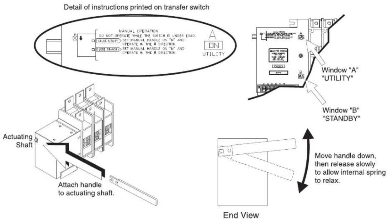
A manual HANDLE is shipped with the transfer switch. Manual operation must be checked BEFORE the transfer switch is operated electrically. To check manual operation, proceed as follows:
- Turn the generator's AUTO/OFF/MANUAL switch to OFF.
- Turn OFF both UTILITY and EMERGENCY power supplies to the transfer switch, with whatever means provided (such as the main line circuit breakers).
- Note position of transfer mechanism main contacts by observing display windows in "A" and "B" in Figure 3.1 as follows:
- Window "A" ON, Window "B" OFF - LOAD terminals (T1, T2, T3) are connected to utility terminals (N1, N2, N3).
- Window "A" OFF, Window "B" ON - LOAD terminals (T1, T2, T3) are connected to emergency terminals (E1, E2, E3).
▲ CAUTION!

Do not use excessive force when operating the transfer switch manually or the manual handle could be damaged.
3.2.1 CLOSE TO NORMAL SOURCE SIDE
Before proceeding, verify the position of the switch by observing window "A" in Figure 3.1. If window "A" reads "ON", the contacts are closed in the normal position, no further action is required. If it reads "OFF", proceed with Step 1.
Step 1: With the handle attached to the actuating shaft, move handle in the direction of the arrow on the switch cover until it stops — DO NOT FORCE. Release handle slowly to allow the spring in the switch box to relax. "ON" now appears in Window "A" and "OFF" appears in Window "B".
Figure 3.1 — Actuating Transfer Switch
DANGER: Do NOT manually transfer under load. Disconnect transfer switch from all power sources by approved means, such as a main circuit breaker(s).
NOTE: Return handle to storage position in enclosure when finished with manual transfer
Operation
3.2.2 CLOSE TO EMERGENCY SOURCE SIDE
Before proceeding, verify the position of the switch by observing window "B" in Figure 3.1. If window "B" reads "ON", the contacts are closed in the EMERGENCY (STANDBY) position. No further action is required. If it reads "OFF", proceed with Step 1.
Step 1: With the handle attached to the actuating shaft, move the handle in the direction of the arrow on the switch cover until it stops - DO NOT FORCE. Release handle slowly to allow the spring in the switch box to relax. "OFF" now appears in Window "A" and "ON" appears in Window "B".
3.2.3 RETURN TO NORMAL SOURCE SIDE
Manually actuate switch to return Window "A" to the "ON" position.
3.3 VOLTAGE CHECKS
3.3.1 UTILITY VOLTAGE CHECKS
- Turn ON the UTILITY power supply to the transfer switch with whatever means provided (such as the UTILITY main line circuit breaker).
⚠️ DANGER!
PROCEED WITH CAUTION. THE TRANSFER SWITCH IS NOW ELECTRICALLY HOT. CONTACT WITH LIVE TERMINALS RESULTS IN EXTREMELY HAZARDOUS AND POSSIBLY FATAL ELECTRICAL SHOCK.
- With an accurate AC voltmeter, check for correct voltage.
Measure across ATS terminal lugs N1 to N2, N2 to N3, and N1 to N3.
Measure across ATS terminal lugs N1 to NEUTRAL, N2 to NEUTRAL, and N3 to NEUTRAL.
- Locate the 3 phase power monitor relay. Verify the following:
208 Vac system - LED green and ON
480 Vac system - LED - NORM indicator (green - ON)
The factory setting is 80% of nominal voltage (208 Vac systems = 166 Vac dropout)
(480 Vac systems = 384 Vac dropout)
- If the LED indicator is not ON, then it will be necessary to adjust the power monitor relay setting. Rotate the adjustment potentiometer in a counter-clockwise direction until the LED turns ON. At this point the 3 phase power monitor relay is the most sensitive to irregular power line conditions.
NOTE:
If the power monitor does not operate properly, check that all three voltages are present, and are of the correct voltage level and phase rotation. To change phase rotation, turn off the utility supply, interchange 2 of the utility power phases.
DANGER!
FAILURE TO TURN OFF THE UTILITY SUPPLY BEFORE WORKING ON THE UTILITY CONNECTIONS OF THE ATS WILL RESULT IN EXTREMELY DANGEROUS AND POSSIBLY FATAL ELECTRICAL SHOCK.
- When certain that UTILITY supply voltage is correct and compatible with transfer switch ratings, turn OFF the UTILITY supply to the transfer switch.
3.3.2 GENERATOR VOLTAGE CHECKS
- On the generator panel, set the AUTO/OFF/MANUAL switch to MANUAL position. The generator should crank and start.
- Let the generator stabilize and warm up at no-load for at least five minutes.
- Set the generator's main circuit breaker (CB1) to its ON or CLOSED position.
⚠️ DANGER!
PROCEED WITH CAUTION. GENERATOR OUTPUT VOLTAGE IS NOW BEING DELIVERED TO TRANSFER SWITCH TERMINALS. CONTACT WITH LIVE TERMINALS RESULTS IN EXTREMELY DANGEROUS AND POSSIBLY FATAL ELECTRICAL SHOCK.
- With an accurate AC voltmeter and frequency meter, check the no-load, voltage and frequency.
Measure across ATS terminal lugs E1 to E2, E2 to E3 and E1 to E3.
Measure across ATS terminal lugs E1 to NEUTRAL, E2 to NEUTRAL and E3 to NEUTRAL.
a. Frequency....60-62 Hz
b. Terminals E1-E2, E2-E3, E1-E3....208-212VAC or 470-485
c. Terminals E1-N, E2-N, E3-N....120-122VAC or 272-282
It will also be necessary to verify that the phase rotation of the utility matches the phase rotation of the generator. This can be done by using a phase rotation indicator.
CAUTION!
Failure to do so may result in damage to certain rotary equipment.
- When certain that UTILITY supply voltage is correct and compatible with transfer switch ratings, turn OFF the UTILITY supply to the transfer switch.
- Set the generator's main circuit breaker (CB1) to its OFF or OPEN position.
- Set the AUTO/OFF/MANUAL switch to the OFF position to shut down the generator.
NOTE:
Do NOT proceed until generator AC output voltage and frequency are correct and within stated limits. If the no-load voltage is correct but no-load frequency is incorrect, the engine governed speed probably requires adjustment. If no-load frequency is correct but voltage is not, the voltage regulator may require adjustment.
3.4 GENERATOR TESTS UNDER LOAD
- Set the generator's main circuit breaker to its OFF or OPEN position.
- Manually actuate the transfer switch main contacts to their EMERGENCY (STANDBY) position. Refer to "Manual Operation".
- To start the generator, set the AUTO/OFF/ MANUAL switch to MANUAL. When engine starts, let it stabilize for a few minutes.
-
Turn the generator's main circuit breaker to the ON or CLOSED position. The generator now powers all LOAD circuits. Check generator operation under load as follows:
-
Turn ON electrical loads to the full rated wattage/amper-age capacity of the generator. DO NOT OVERLOAD.
- With maximum rated load applied, check voltage and frequency across transfer switch terminals E1 and E2. Voltage should be greater than 200 volts (208VAC system), 230 volts (240VAC system), or 460 volts (480VAC system); frequency should be greater than 59 Hz.
-
Let the generator run under rated load for at least 30 minutes. With unit running, listen for unusual noises, vibration, overheating, etc., that might indicate a problem.
-
When checkout under load is complete, set main circuit breaker of the generator to the OFF or OPEN position.
- Let the generator run at no-load for several minutes. Then, shut down by setting the AUTO/OFF/MANUAL switch to its OFF position.
- Move the switch's main contacts back to the UTILITY position. For example, load connected to utility power supply. Refer to "Manual Operation". Handle and operating lever of transfer switch should be in down position.
- Turn on the utility power supply to transfer switch, using whatever means provided (such as a utility main line circuit breaker). The utility power source now powers the loads.
- Set the generator's AUTO/OFF/MANUAL switch to its AUTO position. The system is now set for fully automatic operation.
![430mm[16.9"] 41.5mm[1.6"] MOUNTING HOLES: 26.35mm[20.25"] 4-PLACES 490mm[19.3"] 61.5mm[2.4"] 513.04mm[20.2"]](/content/2026/05/997720/images/6c49030f0ce6d219e25aa49a1cea90dfaf2093fee91a18b78cc0d1dca86646e3.jpg)
![613mm[24.1"] 179.5mm[7.1"] TRIPLE EKO SUITABLE FOR 1", 1.25" & 1.50" CONDUIT 3 PLACES](/content/2026/05/997720/images/407f18a4079ac38da767244b1d8ce3a2dd7c1b2d19a1a804ad271ce95b49a613.jpg)
![61.3mm[2.4"]487mm[19.2"] MOUNTING HOLES: Ø6.35mm[Ø0.25"] 4-PLACES 794mm[31.3"] 60.8mm[2.4"] 609.6mm[24.0"]](/content/2026/05/997720/images/df3004c28e9c5d0c647eea37802713c00901fb373c9b052ee9a60753c7bfad04.jpg)
![917mm[36.1°] 254mm[10.0°] TRIPLE EKO SUITABLE FOR 1", 1.25' & 1.50' CONDUIT 3 PLACES](/content/2026/05/997720/images/abe8de1fcb04c2d0d0d61a02f7da6850ba1a4fccf98d4c21543e89b31bd8f4df.jpg)
![635mm[25.0"] 65.39mm[2.6"] MOUNTING HOLES: Ø6.35mm[Ø0.25"] 4-PLACES 1092mm[43.0"] 63.5mm[2.5"] 765.8mm[30.1"]](/content/2026/05/997720/images/a5bbd8331745dc8bb0c15d8e434970ca6e8ff3844ce1f5afe42ff37b12687420.jpg)
![1220.9mm[48.1"] 332mm[13.1"] TRIPLE EKO SUITABLE FOR 1", 1.25" & 1.50" CONDUIT 3 PLACES](/content/2026/05/997720/images/6eda7901e4681779f8fd7f6d3ca9d239aba48e76b01a775d7c49d35c61124021.jpg)

flowchart
graph TD
    A["QT SERIES ENGINE GENERATOR CONNECTION PANEL"] --> B["3 PHASE"]
    B --> C["SINGLE PHASE"]
    C --> D["RTS TRANSFER SWITCH"]
    D --> E["NEUTRAL BLOCK"]
    E --> F["CUSTOMER LOAD (DISTRIBUTION PANEL)"]
    A --> G["NOTE: 178 AND 183 CONNECTIONS ARE NOT USED IN THIS APPLICATION"]
    D --> H["NOTE: POWER LEADS AND TRANSFER SWITCH LEADS MUST BE RUN IN TWO DIFFERENT CONDUITS."]
    style A fill:#f9f,stroke:#333
    style B fill:#ccf,stroke:#333
    style C fill:#cfc,stroke:#333
    style D fill:#fcc,stroke:#333
    style E fill:#cff,stroke:#333
    style F fill:#ffc,stroke:#333
    style G fill:#f9f,stroke:#333
    style H fill:#ccf,stroke:#333
NOTE: E3, N3 AND T3 WIRES ARE ONLY
USED ON 3 PHASE SYSTEMS
Notes
GENERAC POWER SYSTEMS "FIVE YEAR" LIMITED WARRANTY FOR "STATIONARY EMERGENCY TRANSFER SWITCH SYSTEMS"
For a period of five (5) years from successful activation of the unit (limited to one thousand hours for units in international markets), Generac Power Systems, Inc. (Generac) warrants that its transfer switch system will be free from defects in material and workmanship for the items and period set forth below. Generac will, at its option, repair or replace any part(s) which, upon examination, inspection and testing by Generac or an Authorized/Certified Generac Service Dealer, is found to be defective. Any equipment that the purchaser/owner claims to be defective must be examined by the nearest Authorized/Certified Generac Service Dealer. This warranty applies only to Generac transfer switches used in "Standby" applications as Generac has defined Standby. Scheduled Maintenance, as outlined by the generator owner's manual, is highly recommended. This Scheduled Maintenance should be performed by an Authorized/Certified Generac Service Dealer. This will verify service has been performed on the unit throughout the warranty period.
WARRANTY SCHEDULE
UNITED STATES AND CANADA
YEARS ONE AND TWO – Limited comprehensive coverage on mileage, labor and parts listed.
YEARS THREE THROUGH FIVE – Limited comprehensive coverage on parts listed.
INTERNATIONAL
Limited to 1,000 hours for units in international markets.
- Extended Warranties are not available on units sold into International Markets.
GUIDELINES:
- Travel allowance is limited to 100 miles maximum and three (3) hours per occurrence (whichever is less) round trip from the nearest Authorized/Certified Generac Service Dealer. Any additional travel expences will not be covered by Generac.
- Warranty begins upon the successful activation of the unit.
- Unit should be Registered and Proof of Purchase and Maintenance must be available.
- Warranty is transferable between ownership of original installation site.
- Warranty only applies to permanently wired and mounted units.
- Any and all warranty repairs and/or concerns, must be performed and/or addressed by an Authorized/Certified Generac Service Dealer, or branch thereof. Repairs or diagnostics performed by individuals other than Authorized/Certified Generac Service Dealers not authorized in writing by Generac will not be covered.
- Steel enclosures are warranted against rusting for the first year of ownership only. Damage caused after receipt is the responsibility of the owner and is not covered by this warranty. Nicks, scrapes, dents or scratches to the painted enclosure should be repaired promptly by the owner.
- All warranty expense allowances are subject to the conditions defined in Generac's General Service Policy Manual.
THIS WARRANTY SHALL NOT APPLY TO THE FOLLOWING:
- Any unit built/manufacturer prior to the 2013 Model units.
- Generac generators that utilize non-Generac replacement parts.
- Costs of normal maintenance.
- Units sold, rated or used for "Prime Power", "Trailer Mounted" or "Rental Unit" applications as Generac has defined Prime Power, Trailer Mounted or Rental Unit. Contact a Generac Distributor for Prime Power, Trailer Mounted or Rental Unit definition.
- Damage to transfer switch caused by improper installation or costs necessary to correct installation.
- Units used for Prime Power in place of existing utility power (where utility power is present) or in place of utility power where utility power service does not normally exist.
- Fuel connections other than conventional utility company supplied natural gas systems or conventional LP vapor withdrawal systems.
- Any failure caused by contaminated fuels, oils, coolants/antifreeze or lack of proper fuels, oils or coolants/antifreeze.
- Steel enclosures that are rusting due to the improper installation, location in a harsh or saltwater environment or scratched where integrity of paint applied is compromised.
- Failures due, but not limited, to normal wear and tear, accident, misuse, abuse, negligence or improper installation. This warranty will not cover repair when normal use has exhausted the life of a part.
- Failures caused by any external cause or act of God, such as collision, theft, vandalism, riot or wars, nuclear holocaust, fire, freezing, lightning, earthquake, windstorm, hail, volcanic eruption, water or flood, tornado or hurricane.
- Damage related to rodent and/or insect infestation.
- Products that are modified or altered in a manner not authorized by Generac in writing.
- Covered warranty labor rates are based on normal working hours. Overtime, holiday, or emergency labor costs for repairs outside of normal business hours will be the responsibility of the customer.
- Any incidental, consequential or indirect damages caused by defects in materials or workmanship, or any delay in repair or replacement of the defective part(s).
- Failure due to misapplication.
- Telephone, cellular phone, facsimile, internet access or other communication expenses.
- Living or travel expenses of person(s) performing service, except as specifically included within the terms of a specific unit warranty period.
- Expenses related to "customer instruction" or troubleshooting where no manufacturing defect is found.
Warranty
- Rental equipment used while warranty repairs are being performed and/or overnight freight costs for replacement part(s).
- Costs incurred for equipment used for removal and/or reinstallation of generator, (i.e.: cranes, hoists, lifts, etc.).
- Planes, ferries, railroad, buses, helicopters, snowmobiles, snow-cats, off-road vehicles or any other mode of transport deemed abnormal.
THIS WARRANTY IS IN PLACE OF ALL OTHER WARRANTIES, EXPRESSED OR IMPLIED. SPECIFICALLY, GENERAC MAKES NO OTHER WARRANTIES AS TO THE MERCHANTABILITY OR FITNESS FOR A PARTICULAR PURPOSE. Any implied warranties which are allowed by law, shall be limited in duration to the terms of the express warranty provided herein. Some states do not allow limitations on how long an implied warranty lasts, so the above limitation may not apply to you. GENERAC'S ONLY LIABILITY SHALL BE THE REPAIR OR REPLACEMENT OF PART(S) AS STATED ABOVE. IN NO EVENT SHALL GENERAC BE LIABLE FOR ANY INCIDENTAL OR CONSEQUENTIAL DAMAGES, EVEN IF SUCH DAMAGES ARE A DIRECT RESULT OF GENERAC'S NEGLIGENCE. Some states do not allow the exclusion or limitation of incidental or consequential damages, so the above limitation(s) may not apply to you. This warranty gives you specific legal rights. You also have other rights from state to state.
FOR AUSTRALIA ONLY: Our goods come with guarantees that cannot be excluded under the Australian Consumer Law. You are entitled to a replacement or refund for a major failure and for compensation for any other reasonably foreseeable loss or damage. You are also entitled to have the goods repaired or replaced if the goods fail to be of acceptable quality and the failure does not amount to a major failure. For Service or other product inquiries in Australia, please contact Allpower by phone at 1800-333-428 or visit Allpower's website at www.allpower.com.au.
FOR NEW ZEALAND ONLY: Nothing in this warranty statement excludes, restricts or modifies any condition, warranty right or remedy which pursuant to the New Zealand Legislation (Commonwealth or State) including the Fair Trading Practices Act of 1986 or the Consumer Guarantees Act 1993 (“CGA”) applies to this limited warranty and may not be so excluded, restricted or modified. Nothing in this statement is intended to have the effect of contracting out of the provisions of the CGA, except to the extent permitted by that Act, and these terms are to be modified to the extent necessary to give effect to that intention. If you acquire goods from Generac Power Systems or any of its authorized resellers and distributors for the purposes of a business, then pursuant to section 43(2) of the CGA, it is agreed that the provisions of the CGA do not apply. For Service or other product inquiries in New Zealand, please contact Allpower by phone at 09-269-1160 or visit Allpower’s website at www.allpower.com.nz.
GENERAC POWER SYSTEMS, INC. • P.O. BOX 8 • Waukesha, WI 53187 • Ph: (888) GENERAC (436-3722) • Fax: (262) 544-4851
To locate the nearest Authorized Dealer and to download schematics, exploded parts views and parts lists visit our website: www.generac.com.
Part No. 0K3102 Rev. B (03/13)
Manual técnico
Índice
C - CONTACTOR ACTUATING COIL
GTS - TRANSFER SWITCH CONTACTOR
PM - POWER MONITOR, 3 PHASE UTILITY
TR - RELAY, TRANSFER
TS - TERMINAL STRIP (CUSTOMER CONNECTION)
LS1,LS2,LS3 - LIMIT SWITCHES, ACTUATOR
F1,F2 - FUSE 5A SENSING

NOTES:
1.) ALL CONTACTS SHOWN WITH TRANSFER SWITCH IN UTILITY POSITION.
2.) FOR SINGLE PHASE OPERATION, ADD JUMPER WIRE FROM PM TERMINALS 1 TO 8.

flowchart
graph TD
    A["GTS"] --> B["N1"]
    A --> C["N2"]
    A --> D["N3"]
    A --> E["E1"]
    A --> F["E2"]
    A --> G["T1"]
    A --> H["T2"]
    A --> I["A1"]
    A --> J["A2"]
    A --> K["B1"]
    A --> L["B2"]
    A --> M["T1"]
    A --> N["T2"]
    A --> O["E2"]
    P["TR"] --> Q["N1B"]
    P --> R["N1A"]
    P --> S["PM"]
    P --> T["FS"]
    U["N1B"] --> V["N1A"]
    W["N2A"] --> X["N1B"]
    Y["N1B"] --> Z["N1A"]
    AA["N2A"] --> AB["N1B"]
    AC["N1B"] --> AD["N1A"]
    AE["N1B"] --> AF["N1A"]
    AG["N1B"] --> AH["N1A"]
    AI["N1B"] --> AJ["N1A"]
    AK["N1B"] --> AL["N1A"]
    AM["N1B"] --> AN["N1A"]
    AO["N1B"] --> AP["N1A"]
    AQ["N1B"] --> AR["N1A"]
    AS["Utility 1"] --> AT["TS"]
    AU["Utility 2"] --> AT["TS"]
    AV["Utility 2"] --> AT["TS"]
    AW["Utility 2"] --> AT["TS"]
GROUP G

EXPLODED VIEW: RTS INTERCONNECTION DIAGRAM DRAWING #: 0F6689
REVISION: DATE: 4/25/05
PAGE 1 OF 1
GROUP C
![487mm[19.2"] 61.3mm[2.4"] MOUNTING HOLES: Ø6.35mm[Ø0.25°] 4-PLACES 794mm[31.3"] 60.8mm[2.4"] 609.6mm[24.0"]](/content/2026/05/997720/images/54ea988c7d98eda1dfb15b7c6d53a08c13df8e868b18e812157c835ac1cb394f.jpg)
EXPLODED VIEW: 24X36X10 INSTALL DIAGRAM DRAWING #: 0F6401
PAGE 1 OF 1
![917mm[36.1°] 254mm[10.0°] TRIPLE EKO SUITABLE FOR 1", 1.25" & 1.50" CONDUIT 3 PLACES](/content/2026/05/997720/images/2b3e9745f4cfee9285d2ac81212f6a04d2dad6409defdcd6103dd552b928e0f5.jpg)
REVISION: DATE: 4/21/05

- Technical Manual RTS Automatic Transfer Switch
- Table of Contents
- Safety Rules ......Inside Front Cover General Information ......2
- Installation....3
- Operation 4
- Mounting Dimensions ....8
- Interconnection Diagram ....11
- Notes 12
- Warranty 13
- DANGER!
- WARNING!
- ▲ CAUTION!
- NOTE:
- GENERAL HAZARDS
- INTRODUCTION
- EQUIPMENT DESCRIPTION
- TRANSFER SWITCH DATA DECAL
- TRANSFER SWITCH ENCLOSURE
- SAFE USE OF TRANSFER SWITCH
- INTRODUCTION TO INSTALLATION
- UNPACKING
- MOUNTING
- CONNECTING POWER SOURCE AND LOAD LINES
- ⚠️ DANGER!
- 3-POLE MECHANISM
- Operation
- CONNECTING START CIRCUIT WIRES
- AUXILIARY CONTACTS
- FUNCTIONAL TESTS AND ADJUSTMENTS
- CLOSE TO NORMAL SOURCE SIDE
- CLOSE TO EMERGENCY SOURCE SIDE
- RETURN TO NORMAL SOURCE SIDE
- VOLTAGE CHECKS
- UTILITY VOLTAGE CHECKS
- PROCEED WITH CAUTION. THE TRANSFER SWITCH IS NOW ELECTRICALLY HOT. CONTACT WITH LIVE TERMINALS RESULTS IN EXTREMELY HAZARDOUS AND POSSIBLY FATAL ELECTRICAL SHOCK.
- FAILURE TO TURN OFF THE UTILITY SUPPLY BEFORE WORKING ON THE UTILITY CONNECTIONS OF THE ATS WILL RESULT IN EXTREMELY DANGEROUS AND POSSIBLY FATAL ELECTRICAL SHOCK.
- GENERATOR VOLTAGE CHECKS
- PROCEED WITH CAUTION. GENERATOR OUTPUT VOLTAGE IS NOW BEING DELIVERED TO TRANSFER SWITCH TERMINALS. CONTACT WITH LIVE TERMINALS RESULTS IN EXTREMELY DANGEROUS AND POSSIBLY FATAL ELECTRICAL SHOCK.
- CAUTION!
- Failure to do so may result in damage to certain rotary equipment.
- GENERATOR TESTS UNDER LOAD
- Notes
- GENERAC POWER SYSTEMS "FIVE YEAR" LIMITED WARRANTY FOR "STATIONARY EMERGENCY TRANSFER SWITCH SYSTEMS"
- WARRANTY SCHEDULE
- UNITED STATES AND CANADA
- INTERNATIONAL
- GUIDELINES:
- THIS WARRANTY SHALL NOT APPLY TO THE FOLLOWING:
- Warranty
- Manual técnico
- Índice
- NOTES:
Brand : Generac
Model : RTSN100K3
Category : Switch