
PKD24B - Dishwasher Perlick - Free user manual and instructions
Find the device manual for free PKD24B Perlick in PDF.


| Product Type | Built-in Dishwasher |
| Brand | Perlick |
| Model | PKD24B |
| Width | 24 inches |
| Depth | 24 inches |
| Height | 34.5 inches (adjustable) |
| Weight | 95 lbs |
| Power Supply | 120V / 60Hz / 15A |
| Energy Star Rated | Yes |
| Place Settings | 14 place settings |
| Noise Level | 44 dBA |
| Wash Cycles | Normal, Heavy, Light, Rinse Only, Sanitize |
| Wash System | Quad-Wash with spray arms |
| Drying System | Heated Dry with fan assist |
| Material | Stainless steel interior and exterior |
| Control Type | Electronic touchpad with LED display |
| Filter | Self-cleaning filter |
| Water Consumption | 3.2 gallons per cycle |
| Energy Consumption | 295 kWh/year |
| Safety Features | Child lock, flood protection |
| Warranty | 2 years parts and labor |
Frequently Asked Questions - PKD24B Perlick
User questions about PKD24B Perlick
0 question about this device. Answer the ones you know or ask your own.
Ask a new question about this device
Download the instructions for your Dishwasher in PDF format for free! Find your manual PKD24B - Perlick and take your electronic device back in hand. On this page are published all the documents necessary for the use of your device. PKD24B by Perlick.
USER MANUAL PKD24B Perlick
Keep with machine for reference
PKD24B
Perlick Corporation
8300 W Good Hope Rd
Milwaukee, WI 53223
800-558-5592
FAX 414-353-7069
Perlick.com
TABLE OF CONTENTS
PKD24B
1. SPECIFICATIONS....2
1.1. PKD24B ....ERROR! BOOKMARK NOT DEFINED.
1.2. PKD24B OPERATIONAL CYCLE 3
2. GETTING STARTED ....5
2.1. INTRODUCTION TO THE PKD24B 5
2.2. RECEIVING AND INSTALLATION 6
2.2.1. Electrical 6
2.2.2. Plumbing....6
2.2.3. Post Instructions 6
2.2.4. Installers Checklist 7
3. OPERATION....8
3.1. INITIAL SETUP 8
3.1.1. Check.... 8
3.1.2. Chemicals 8
3.1.3. Filling the Machine 8
3.2. GENERAL....8
3.2.1. Pre-Scrapping....8
3.2.2. Proper Chemical Dosage 8
3.2.3. Proper Filling....9
3.2.4. Water Pump 9
3.2.5. Pump Cavitation....9
4. MAINTENANCE....10
4.1. TIMER ASSEMBLY 10
4.1.1. Cam Adjustment.... 10
4.2. QUICK SERVICE GUIDE.... 11
4.3. TROUBLESHOOTING.... 12
5. ADDENDUM FOR MACHINES INSTALLED IN THE CITY OF CHICAGO .15
APPENDIX A: OPERATOR & CLEANING INSTRUCTIONS ....16
6. ELECTRICAL DIAGRAM (EFFECTIVE 06/2007) ......18
1. Specifications
1.1. PKD24B
METRIC
EQUIVALENT
| WATER CONSUMPTION | ||
| PER RACK | 1.7 GAL. | 6.44 L |
| PER HOUR 40.8 GAL. 154.4 L | ||
| OPERATING CYCLE | ||
| WASH TIME-SEC | 57 | 57 |
| RINSE TIME-SEC | 48 | 48 |
| DWELL TIME-SEC | 15 | 15 |
| TOTAL CYCLE 2 MIN. 2 MIN. | ||
| OPERATING CAPACITY | ||
| RACKS PER HOUR 30 30 | ||
| WASH TANK CAPACITY | 1.7 GAL. | 6.44 L |
| PUMP CAPACITY 35 GPM 132.5 LPM | ||
| WATER REQUIREMENTS | 140°F | 60°C |
| WATER INLET | 1/2" | 1.27cm |
| DRAIN CONNECTION | 1" | 2.54 cm |
| CYCLE TEMPERATURES | ||
| WASH-°F (Min) | 140 | 60°C |
| FRAME DIMENSIONS | ||
| DEPTH | 23 1/2" | 59.69 cm |
| WIDTH | 24" | 60.96 cm |
| PKD24B HEIGHT | 30" | 76.2 cm |
| PKD24B MAX CLEARANCE FOR GLASSES | 12 1/4" | 31.11 cm |
| ELECTRICAL* | 115 VAC | |
| 15.8 AMPS | ||
| SUSTAINER HEATER(Not Booster Heater) | 0.8 kW | |
| WASH PUMP MOTOR | 13.4 AMPS | |
| *MUST CONNECT TO DEDICATED 20 AMP SUPPLY CIRCUIT.COMPLIANCE WITH LOCAL ELECTRICAL CODES MUST BE FOLLOWED. | ||
| SHIPPING WEIGHT | ||
| PKD24B (Approximate) | 190# | 86.2 kg |

WARNING: California Prop 65 Notice
These products may expose you to chemicals including Chromium, which are known to the state of California to cause cancer and birth defects or other reproductive harm. For more information on whether a product in this list contains these chemicals, please refer to the specific product page at perlick.com. Or to find out more about Prop 65, go to P65Warnings.ca.gov.
1.2. PKD24B Operational Cycle
The PKD24B Operational Cycle has a total cycle time of 2 minutes (120 seconds). The Timing Diagram and the steps listed below detail the individual functions that are executed during each Operational Cycle.

- With the machine powered up, toggling the START switch begins a cycle.
a) Toggling the START switch energizes both the cam timer motor and the instant start relay. The instant start relay latches ON the power to the cam timer motor so that the START switch can be released a moment after it has been toggled without the cam timer motor losing power.
b) After about 2 seconds, Cam 1—the Start cam—latches ON the power to the cam timer motor and drops out the instant start relay. The cam timer motor continues to run for a total of 2 minutes, at which time it switches OFF—resetting the cam timer—and waits for the next start command.
- Cam switch 7 controls the pump motor. The pump motor comes ON at the beginning of the operational cycle and continues to run until the end of the drain function (controlled by cam switch 3), at which time it turns off for about eight seconds allowing time for the machine to refill enough to avoid running the pump dry before the pump motor restarts and runs to the completion of the operational cycle.
The pump motor runs the pump for the 57-second wash cycle, then pumps the water out through the drain, turns off for about 8 seconds (allowing the machine to refill with clean rinse water) and then runs the pump for the 48-second rinse cycle.
- Cam switch 3 controls the drain function. At the end of the 57-second wash cycle, cam switch 3 energizes the drain valve solenoid allowing the pump motor to drain the wash water out of the machine. Cam switch 3 also increments the rack counter by one each cycle.
- Cam switch 4 controls the water valve solenoid on the water supply to flush and fill the machine. At the end of the wash cycle the drain valve is opened, the pump motor continues to run (to pump the wash water out through the drain), and the Flush function begins. At first, flushing the machine because the drain valve is still open, then—with the drain valve closed and the pump motor stopped—the machine begins to fill for the rinse cycle. Once the machine has refilled sufficiently, the pump motor restarts carrying out the rinse portion of the cycle as the filling of the wash tank completes.
- Cam switch 2 controls the detergent pump and turns ON about 5 seconds after the operational cycle is started and runs for a few seconds to provide sufficient detergent for the wash cycle. This cam can be adjusted as necessary for proper detergent dosage.
See section 4.1.1 Cam Adjustment
-
Cam switches 5 and 6 control the sanitizer and rinse pumps respectively. They turn ON at the beginning of the rinse cycle and run for a few seconds to provide sufficient sanitizer and rinse aid for the rinse cycle. These cams can be adjusted as necessary for proper chemical dosage. See section 4.1.1 Cam Adjustment
-
Cam switch 8 operates the optional sustainer heater. This cam assures that the sustainer heater only turns on when the glasswasher is not in a cycle. This prevents the machine from drawing too much electrical current at any one time.
2. Getting Started
All sections of the manual address the PKD24B. Separate information on each machine is only provided where differences exist between the two models.
2.1. Introduction to the PKD24B
The PKD24B glasswasher are unique in their field; they have all the features of a standard commercial size machine packed into an under-counter, standalone glasswasher.
Operation of the PKD24B IS extremely easy. After initially filling the machine (see section 3.1.3 Filling the Machine), toggling the Fill/Start switch to the "START" position begins the Operational Cycle, which runs automatically.
To reduce service time, all electrical components are mounted in a sliding drawer for easy access. This “Works-In-A-Drawer” can be removed by unplugging a single connector for easy serviceability.
The only external connections necessary are the power source, water supply and drainpipe.
There are also accessories that can be chosen when desired such as the optional sustainer heater and 6" legs. The optional sustainer heater with thermostat is extremely practical for maintaining wash tank temperature between cycles. The 800 watt heater will hold the wash tank temperature between 130°F and 140°F while the machine is not being run. See parts manual for the parts list and accessories available for the machine.
The supply water to the PKD24B must be a minimum of 140° F. The pipe supplying the water must be 1/2 " minimum. The plumbing connection is located at the back of the machine. The drain is a 1" barbed fitting located at the back of the machine for easy attachment of your drain hose. See section 2.2.2 Plumbing.
This manual is structured to provide a complete reference guide to the PKD24B. It is presented in a manner that all users will be able to comprehend and use as an effective tool in supporting the installation, operation and maintenance of the glasswasher. The first section provides the specifications and details of the operational cycle. The next section explains how the machine is packaged and what to look for when receiving the machine. After unpacking the machine, this manual explains how to install and set up the machine for use. Requirements are given for plumbing, wiring, and space considerations. These attributes of the machine are always taken into consideration by our well-trained sales representatives prior to the order being placed. In the manual, guidance is also given for operation to ensure that the machine will be able to run optimally.
The Operation section of the manual may be used for instruction and procedures when required. We make this portion of the manual easy to understand so that all levels of operators may be able to read and comprehend the operation of the machine. The function of the machine itself is mostly automatic and takes little training to put into full operation. The Operation section also includes diagnostic considerations for the machine if problems occur.
The Maintenance section of the manual is for qualified personnel and provides trouble shooting procedures and specific maintenance instructions.
The final section of the manual is the Parts Manual. This section has the parts lists and wiring diagram for the machine.
Perlick warranties the workmanship of the machine.
At Perlick we are committed to providing the best machines and customer service in the food and beverage industry and your feedback is welcome.
2.2. Receiving and Installation
The glasswasher is shipped from the factory in a corrugated box on a wooden pallet. The installation guidelines give a systematic procedure for setting up the machine.
- Start by removing the box and packaging material. Check for the following component parts:
A. Drain Screen:
The Wash Tank Scrap Screen is shipped inside the wash cavity of the machine. This screen must be in place during operation. It has been designed to perform two basic functions:
- Strain water that is circulating through the spray arms and pump assembly.
- A basket to catch heavy solids or broken glass that may plug the impeller.
B. Spray Arms
The end caps on the spray arms have been taped to protect them in shipping. Remove the tape from the spray arm end caps.
C. Tube Stiffeners:
The tube stiffeners must be used to prevent the feed tubes from curling up inside the chemical pail allowing the tip to rise out of the chemical. Remove the tie-wraps securing the tube stiffeners to the glasswasher to free them up for use. Be careful not to remove any of the tie-wraps securing the tube bundle.
- Set the machine in place and, using the leg adjusters, level from side-to-side and front-to-back.
2.2.1. Electrical *
A 20-amp, 115 volt, 60 Hz dedicated circuit must be used to supply electrical power to the PKD24B glasswasher (see specification sheet page 1). The power connection must be such that there is sufficient length of flexible conduit or power cord to permit the machine to be moved for cleaning.
2.2.2. Plumbing *
The machine is equipped with a gate valve with a 1/2 " female NPT connection located at the lower left-hand corner (facing the back) of the machine. A 140° F water line should be plumbed to this point. The water line used must be of sufficient length and flexibility to permit the machine to be moved for cleaning.
A 1" male NPT fitting is provided for the drain connection on the discharge port of the diverter valve (lower, right-hand corner of machine). This fitting may be removed and user provided hardware may be used if necessary to facilitate compliance with local plumbing codes. Code requires that the drain discharge provides an air gap no less than 1" or two pipe diameters, whichever is greater, above the flood level rim of an approved floor drain.
2.2.3. Post Instructions
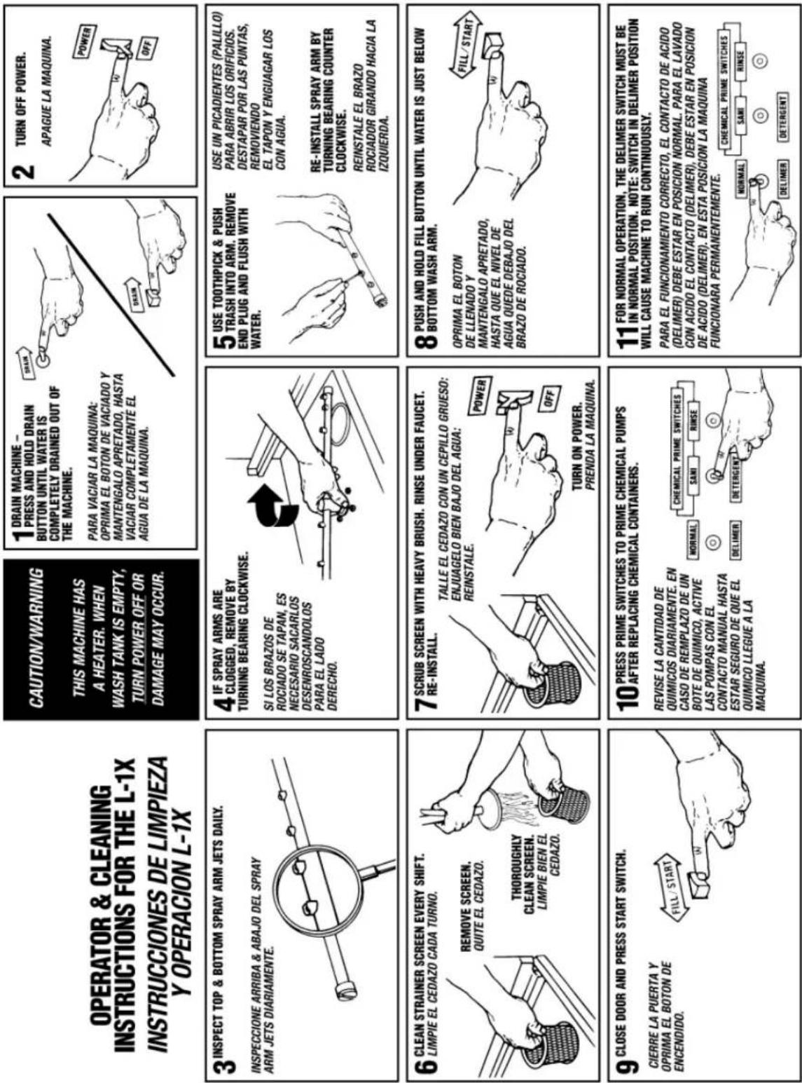
Mount the wall chart provided in a conspicuous place and instruct the operators on proper cleaning and operation of the PKD24B. The instruction chart is also provided as an appendix to this manual (see appendix).
2.2.4. Installers Checklist
□ Glasswasher checked for concealed damage
☐ Hot water supply is 140° F (60 C)
☐ Incoming water supply line is 1/2 " minimum
□ Supply circuit breaker for machine is properly sized (20 amp)
☐ Service voltage and phase type are correct to machine data plate
☐ Drain hose is installed with adequate air gap
□ Glasswasher is properly grounded
□ Glasswasher is properly leveled
□ Machine circuit breaker is labeled "Glasswasher"
☐ Machine has been connected with correctly sized wire (12 gauge minimum)
3. Operation
3.1. Initial Setup
3.1.1. Check...
√ Drain screen is in place
☑ Spay arms and end plugs are secure
3.1.2. Chemicals
• Assure there is a sufficient supply of chemicals before beginning a shift.
3.1.3. Filling the Machine
- With the power ON, press and hold the Fill/Start switch in the "FILL" position until the water level in the wash tank is about 1" deep, for best results use water level indicator located at the back of the wash tank.
3.2. General
Caution: Do not operate the glasswasher without the drain screen in place. Debris getting into the pump impeller can damage the pump.
- Load a rack of properly pre-scrapped dished into the machine and close the door.
- With the machine filled to the proper level, toggle the Fill/Start rocker switch to the "START" position – the machine will automatically begin its cycle. The green running light on the switch will illuminate while an operational cycle is in process.
- At the end of the shift, drain the machine by holding the Drain rocker switch in the "DRAIN" position until the machine is completely drained. To avoid running the pump dry, do not hold the Drain rocker switch in the "DRAIN" position any longer than necessary.
- Remove and clean the drain screen. Remove and clean the spray arms. (See wall chart instructions or instructions provided in Appendix A: Operator & Cleaning Instructions).
- Replace the drain screen and spray arms.
3.2.1. Pre-Scrapping
It is essential that the operator thoroughly understand the importance of pre-scraping the dishes before loading them. The PKD24B is equipped with a removable drain screen. The drain screen can be easily removed for cleaning between Operational Cycles of the glasswasher. Properly pre-scraping the dishes should permit the glasswasher to operate for an entire shift before needing to remove and clean the drain screen.
3.2.2. Proper Chemical Dosage
The amount of chemical delivered, whether it is detergent, sanitizer or rinse aid, is determined by its respective cam on the cam timer.
• Cam number 2 runs the detergent pump
• Cam number 5 runs the sanitizer pump
• Cam number 6 runs the rinse aid pump
These cams were set at the factory but can be adjusted after final installation to maximize efficiency of chemical use (see section 4.1.1 Cam Adjustment.)
3.2.3. Proper Filling
The amount the machine is automatically filled each cycle is determined by the number 4 cam. When the number 4 cam switch actuator rides down into the cam groove, the solenoid valve on the fill line is energized causing the machine to fill. Since the cam only controls the duration of the fill, varying water pressure can vary the amount the machine fills. If the water pressure at the facility where the machine is installed is enough higher or lower than the water pressure was at the factory, the number 4 cam may need to be adjusted to correct the difference (see section 4.1.1 Cam Adjustment). The machine should be filling to a level about 1" deep over the entire bottom of the wash tank, or just below the lower wash arm. If the water pressure at the facility varies throughout the day, a pressure regulator may have to be installed on the water supply line to the machine to maintain constant pressure.
Note: If the optional sustainer heater is installed, the wash tank must be properly filled, and the machine properly leveled, or the float switch, which prevents the heater from turning on if the level is too low, will not permit the heater to turn on.
3.2.4. Water Pump
The water pump takes in water from the drain sump and pumps it to the spray nozzles at a rate of 68 gallons per minute and a pressure at the nozzles of approximately 7 to 10 PSI. After being released through the spray arms and washing or rinsing the dishes, the water runs down the pan to the sump, through the drain screen, and back to the pump.
The pump is driven by a 115 volt, 1 HP motor operating at 3450 RPM. The impeller is mounted with a right-hand thread onto a 5/8" stainless steel shaft, which is coupled to the motor armature shaft.
3.2.5. Pump Cavitation
By listening to the normal pumping sound of the motor it can be determined if there is insufficient water in the machine, as you will hear a hesitation in the normal pumping rhythm, which is created by the air getting into the pump. Cam 4 can be adjusted to increase the amount of water that is automatically fed into the machine during a cycle (see section 4.1.1 Cam Adjustment).
4. Maintenance
The maintenance procedures detailed in this section are to be performed by qualified personnel.
4.1. Timer assembly
The standard timer assembly consists of a 1/2 RPM (2 minutes per revolution) motor turning a common shaft, which, in turn, rotates eight cams. As the cams rotate, they control various functions and the sequence of the operational cycle.
The individual function of each of the 8 cams is identified by a label on the timer assembly. Cams 1 through 8 are positioned from left to right beginning with the "START" cam (cam 1).

Timer Assembly Label
*The "HEATER" label is not present if the optional sustainer heater is not installed on the machine.
Except for cams 1, and 3, all other cams can be user adjusted. The cam positions are all set at the factory and only the cams controlling the chemical pumps (cams 2, 5 & 6) should ever need adjusting. Each micro switch on the timer assembly is turned on and off by the cam its actuator rides on. For all of the cams, except cams 1, 7 and 8, its corresponding switch is ON when its actuator is down in the cam groove. (Cams 1, 7 and 8 are reverse acting and are turned ON when the micro switch actuator is up out of the groove.) Opening the groove of any cam other than cams 1, 7 or 8 will increase the amount of time that the micro switch is held ON. The cams are slip-fit and a cam adjustment wrench is provided (a small screw driver or the edge of a table knife can also work to adjust the cams).
4.1.1. Cam Adjustment
The two sides of each cam connect to the shaft with a slip-fit so all cam adjustments are made by rotating one side of the cam on the shaft to either increase or decrease the size of the cam groove.
- Turn off the circuit breaker providing power to the machine before pulling the control drawer out to access the timer assembly.
Caution: One of the terminals on the main power switch remains "hot" even when the machine's main power switch is turned off—so turn the power off at the circuit breaker. - Remove the two 8–32 x 1/2" Screws securing the control drawer and slide it out to its fully extended position.
- Using the timer assembly label, determine which cam is to be adjusted. Double check by counting over from cam 1 to the cam to be adjusted.
- Determine which edge of the cam groove to be adjusted is the leading edge (contacts the limit switch actuator first when the shaft is rotating) and which edge of the groove is the trailing edge. The leading edge of the cam groove determines when in the cycle the control action begins and should not be changed.
- Adjust the trailing edge of the cam groove by rotating the appropriate side of the cam in the proper direction to either increase or decrease the cam's groove; resulting in increasing or decreasing the total time that switch will be held ON.
4.2. Quick service guide
| TECHNICAL ISSUE | CAUSE | SOLUTION |
| Wash Pump motor will not shut off | Delimer switch in delime position | Flip to NORMAL position |
| Faulty delimer switch | Replace switch, P/N 00475.30 | |
| Faulty manual drain switch | Replace switch, P/N 03406.62 | |
| Faulty contactor | Replace contactor, P/N 00404.82 | |
| Continues cycles | Faulty #1 micro switch (start/stop) | Replace switch, P/N 00411.00 |
| Faulty start/fill switch | Replace switch, P/N 03470.01 | |
| Sustainer heater not working | Faulty #1 micro switch | Replace switch, P/N 00411.00 |
| Low water level inside machine | Add water to tank to activate float switch, adjust water cam on timer | |
| Faulty float switch | Replace switch, P/N 13463.10 | |
| Machine not level | Level machine | |
| Faulty ice cube relay | Replace relay, P/N 00631.00 | |
| Machine does not drain | Faulty #3 micro switch (drain) | Replace switch, P/N 00411.00 |
| Faulty drain valve | Replace drain valve, P/N 04103.00 | |
| Does not hold water | Faulty #3 micro switch (drain) | Replace switch, P/N 00411.00 |
| Clogged or defective drain valve | Clean and/or replace drain valve, P/N 04103.00 | |
| Tank overflows overnight | Debris in water Solenoid Valve | Clean and replace valve diaphragm, P/N 00707.00 |
| Water leaks out of Vacuum Breaker | Dirty or defective vacuum breaker kit assy | Clean or replace internal parts, P/N 03623.00 |
| Faulty check valve | Replace check valve, P/N 00715.00 | |
| Wash Pump motor not running | Male/female plug on the back of control drawer is loose | Secure plug |
| Faulty door reed switch | Replace reed switch, P/N 00557.55 | |
| Faulty 7th micro switch | Replace switch, P/N 00411.00 | |
| Faulty motor contactor | Replace contactor, P/N 00404.82 | |
| Timer does not rotate | Faulty Start/Fill Switch | Replace switch, P/N 03470.01 |
| Faulty #1 micro switch | Replace switch, P/N 00411.00 | |
| Faulty timer motor | Replace motor assembly, P/N 00501.00 | |
| Machine does not fill | Faulty #4 Micro switch | Replace switch, P/N 00411.00 |
| Debris inside water solenoid valve or Faulty valve | Clean and replace valve diaphragm, P/N 00707.00 | |
| Faulty water solenoid coil | Replace solenoid coil, P/N 00738.10 | |
| Sanitizer pump does not run | Delimer switch in wrong position | Switch to NORMAL position |
| Faulty 5th micro switch | Replace switch, P/N 00411.00 | |
| Faulty sanitizer pump motor | Replace motor, P/N 00416.00 |
4.3. Troubleshooting
| PROBLEM | LIKELY CAUSE | SOLUTION |
| Machine inoperative | Power off at circuit breaker | Reset circuit breaker |
| Defective power switch | Replace power switchP/N: 00433.10 | |
| Defective timer assembly motor Replace timer assembly motorP/N: 00501.00 | ||
| Pump Motor inoperative | Door is open | Close door |
| Control drawer is pulled out Secure control drawer | ||
| Defective reed (door) switch Replace reed (door) switchP/N: 00557.55 | ||
| Defective timer assembly(Cam 7) | Replace timer assembly*P/N: 00408.80 | |
| Defective pump motor contactor | Replace contactorP/N: 00404.82 | |
| Defective pump motor Replace pump motorP/N: 00201.00 | ||
| Pump Motor runs with door open | Defective reed (door) switch Replace reed (door) switchP/N: 00557.55 | |
| Defective pump motor contactor Replace contactorP/N: 00404.82 | ||
| Delime switch is on | Turn off delime switch | |
| Motor runs continuously | Delime switch is on | Turn off delime switch |
| Optional Sustainer Heater(no heat) | Defective thermostat on heater Replace heaterP/N: 04109.10 | |
| Defective heater relay | Replace heater relayP/N: 00631.00 | |
| Defective timer assembly(Cam 8) | Replace timer assembly *P/N: 00408.80 | |
| Defective heater | Replace heaterP/N: 04109.10 | |
| Defective float switch | Replace float switchP/N: 13463.00 | |
| Float switch not actuated | Fill wash tank completely | |
| Level machine | ||
| Optional Sustainer Heater(never turns off) | Defective thermostat on heater Replace heaterP/N: 04109.10 | |
| Defective timer assembly(Cam 8) | Replace timer assembly *P/N: 00408.80 | |
| Defective heater relay | Replace heater relayP/N: 00631.00 | |
*The timer assembly motor (P/N: 00501.00) or micro switches (P/N: 00411.00) can be replaced independently if that is the only component that has failed.
| PROBLEM | LIKELY CAUSE | SOLUTION |
| Low heat during operation | Low incoming water temperature (below 140°F) | Turn up supply water heater |
| Insulate supply water pipe | ||
| Thermostat out of adjustment Adjust thermostat | ||
| (Optional) sustainer heater not installed | Install (optional) sustainer heaterP/N: 04109.10 | |
| Defective sustainer heater | Replace heaterP/N: 04109.10 | |
| Low spray arm water flow | Limed up spray arm nozzles | De-lime spray arm nozzles |
| With power on, activating start switch does not begin cycle | Defective fill/start switch (cycle light will not light either) | Replace fill/start switchP/N: 03470.01 |
| Defective timer assembly (Cam 1) | Replace timer assembly*P/N: 00408.80 | |
| Start switch requires more than 1-second activation to run cycle | Defective (Instant Start) ice cube relay | Replace ice cube relayP/N: 00631.00 |
| Activating fill switch does not fill machine | Defective fill/start switch Replace fill/start switchP/N: 03470.01 | |
| Defective water solenoid valve Replace water solenoid valveP/N: 03603.10 | ||
| Fill water won't shut off | Defective water solenoid valve | Replace water solenoid valveP/N: 03603.10 |
| Defective fill/start switch Replace fill/start switchP/N: 03470.01 | ||
| Defective timer assembly (Cam 4) | Replace timer assembly*P/N: 00408.80 | |
| Activating drain switch does not drain machine | Drain hose is kinked | Un-kink drain hose |
| Defective drain switch Replace drain switchP/N: 03406.64 | ||
| Defective drain valve motor (Pump will still run) | Replace drain valve motorP/N: 04103.21 | |
| Detergent pump does not run | Defective detergent pump motor Replace pump motorP/N: 00416.00 | |
| Defective timer assembly (Cam 2) | Replace timer assembly*P/N: 00408.80 | |
| Sani pump does not run | Defective sani pump motor | Replace pump motorP/N: 00416.00 |
| Defective timer assembly (Cam 5) | Replace timer assembly*P/N: 00408.80 | |
*The timer assembly motor (P/N: 00501.00) or micro switches (P/N: 00411.00) can be replaced independently if that is the only component that has failed.
| PROBLEM | LIKELY CAUSE | SOLUTION |
| Rinse pump does not run | Defective rinse pump motor | Replace pump motorP/N: 00416.00 |
| Defective timer assembly(Cam 6) | Replace timer assembly*P/N: 00408.80 | |
| Activating detergent primer switch does not run pump | Defective sani/detergent primer switch | Replace primer switchP/N: 03470.00 |
| Defective detergent pump motor | Replace pump motorP/N: 00416.00 | |
| Activating sani primer switch does not run pump | Defective sani/detergent primer switch | Replace primer switchP/N: 03470.00 |
| Defective sani pump motor Replace pump motorP/N: 00416.00 | ||
| Activating rinse primer switch does not run pump | Defective rinse primer switch Replace primer switchP/N: 03470.00 | |
| Defective rinse pump motor Replace pump motorP/N: 00416.00 | ||
| Counter does not increment | Defective counter Replace counterP/N: 03408.50 | |
| Defective timer assembly(Cam 3) | Replace timer assembly*P/N: 00408.80 | |
| Running light does not light while cycle runs | Defective cycle light | Replace running light (green)P/N: 00476.00 |
| Power light does not light but machine runs | Defective power light | Replace power light (red)P/N: 00406.00 |
| Wash tank temperature gauge displays wrong temperature | Defective temperature gauge Replace temperature gaugeP/N: 03202.00 | |
| Delime switch does not activate pump motor | Defective delime switch | Replace delime switchP/N: 00475.30 |
| Defective pump motor Replace pump motorP/N: 00201.00 | ||
*The timer assembly motor (P/N: 00501.00) or micro switches (P/N: 00411.00) can be replaced independently if that is the only component that has failed.
5.Addendum for Machines Installed in the City of Chicago
"All food dispensing establishments using chlorine or other approved chemical sanitizers shall, at all times, maintain an adequate testing device."
"Dishes and other eating and drinking utensils to be washed in a dishwashing machine shall be properly scraped and pre-rinsed and shall be stacked in racks or trays so as to avoid overcrowding, and so as to permit the wash and rinse waters to reach all surfaces of each utensil."
"In machine washing, multi-use eating and drinking utensils shall be washed in water containing a suitable detergent at a temperature of 120°F to 140°F or other method approved by the Department of Health."
"The water in the wash tank shall be changed during operation as often as is necessary to keep it reasonably clean. An effective concentration of detergent in the wash water shall be maintained at all times."
"Bactericidal treatment shall consist of exposure of all surfaces of dishes and utensils being washed to a rinse of clean water, at a temperature of not less than 180°F or other method approved by the Department of Health."
"All dishwashing machines shall maintain a flow pressure not less than 15 or more than 25 pounds per square inch on the fresh water line at the machine and not less than 10 pounds per square inch at the rinse nozzles. A suitable gauge cock shall be provided immediately upstream from the final rinse sprays to permit checking the flow of the final rinse water. An easily readable thermometer accurate to a ± 2° F. shall be provided on both the wash and rinse water lines of the dishwashing machine which will indicate the temperature of the water solution there in."
"Dishwashing machines shall be thoroughly cleaned at least once each day. The pumps and the wash and rinse sprays or jets shall be so designed that a forceful stream of water will reach all surfaces of the utensils when they are properly racked. These parts shall be thoroughly cleaned at least once each day. The pumps and the wash and rinse sprays or jets shall be designed that a forceful stream of water will reach all surfaces of the utensils when they are properly racked. These pars shall be readily accessible for inspection and cleaning.
"After bactericidal treatment, utensils and containers shall be stored at a sufficient height above the floor in a clean, dry place, protected from flies, splash, dust, overhead leakage and condensation, and other contamination. Containers and utensils shall be inverted, covered, or otherwise protected from contamination until used for serving."
Drain racks, trays and shelves shall be made of non-corrodible material and shall be kept clean. In handling containers and utensils the surfaces thereof which come in contact with food or drink shall not be touched by the hands, except during the process of washing. Tables for clean and dirty dishes and food shall be so arranged that the dirty dishes will be as far removed from the food and clean dishes as may be possible.
All single service articles and utensils shall be purchased in sanitary cartons and stored in a clean, dry place until used, and after removal from the cartons, these articles shall be handled in such a manner as to prevent contamination.
Please note the following procedures must be followed for City of Chicago Approval:
- All low energy models must have low level sani-alarms, both visual and audio.
- All models must have a City of Chicago approval data label affixed to the machine.
- Chlorine sanitizer must be a minimum of 100 PPM.
Appendix A: Operator & Cleaning Instructions
- Electrical Diagram (Effective 06/2007)

- PKD24B
- TABLE OF CONTENTS
- SPECIFICATIONS....2
- GETTING STARTED ....5
- OPERATION....8
- MAINTENANCE....10
- ADDENDUM FOR MACHINES INSTALLED IN THE CITY OF CHICAGO .15
- APPENDIX A: OPERATOR & CLEANING INSTRUCTIONS ....16
- ELECTRICAL DIAGRAM (EFFECTIVE 06/2007) ......18
- SPECIFICATIONS
- WARNING: CALIFORNIA PROP 65 NOTICE
- PKD24B OPERATIONAL CYCLE
- SEE SECTION 4.1.1 CAM ADJUSTMENT
- GETTING STARTED
- INTRODUCTION TO THE PKD24B
- RECEIVING AND INSTALLATION
- ELECTRICAL
- PLUMBING
- POST INSTRUCTIONS
- INSTALLERS CHECKLIST
- OPERATION
- INITIAL SETUP
- CHECK
- CHEMICALS
- FILLING THE MACHINE
- GENERAL
- PRE-SCRAPPING
- PROPER CHEMICAL DOSAGE
- PROPER FILLING
- WATER PUMP
- PUMP CAVITATION
- MAINTENANCE
- TIMER ASSEMBLY
- TIMER ASSEMBLY LABEL
- CAM ADJUSTMENT
- 5.ADDENDUM FOR MACHINES INSTALLED IN THE CITY OF CHICAGO
- APPENDIX A: OPERATOR & CLEANING INSTRUCTIONS
Brand : Perlick
Model : PKD24B
Category : Dishwasher