
PKHT24 - Dishwasher Perlick - Free user manual and instructions
Find the device manual for free PKHT24 Perlick in PDF.


| Brand | Perlick |
| Model | PKHT24 |
| Product Type | Built-In Dishwasher |
| Installation Type | Under Counter |
| Height | 34.5 inches |
| Width | 24 inches |
| Depth | 24 inches |
| Weight | 85 lbs |
| Power Supply | 120 V, 60 Hz, 15 A |
| Wash Cycles | 7 (Heavy, Normal, Light, Rinse, Quick, Eco, Sanitize) |
| Noise Level | 44 dBA |
| Water Usage | 3.5 gallons per cycle (Normal) |
| Energy Consumption | 270 kWh/year |
| Place Settings | 14 |
| Drying System | Heated Dry with Fan Assist |
| Interior Material | Stainless Steel |
| Cutlery Basket | Third rack with adjustable dividers |
| Adjustable Racks | Upper rack height adjustable |
| Child Lock | Available |
| Control Type | Electronic touch panel with LED display |
| Delay Start | Up to 24 hours |
| Soil Sensor | Automatic cycle adjustment |
| Certifications | Energy Star, NSF |
Frequently Asked Questions - PKHT24 Perlick
User questions about PKHT24 Perlick
0 question about this device. Answer the ones you know or ask your own.
Ask a new question about this device
Download the instructions for your Dishwasher in PDF format for free! Find your manual PKHT24 - Perlick and take your electronic device back in hand. On this page are published all the documents necessary for the use of your device. PKHT24 by Perlick.
USER MANUAL PKHT24 Perlick
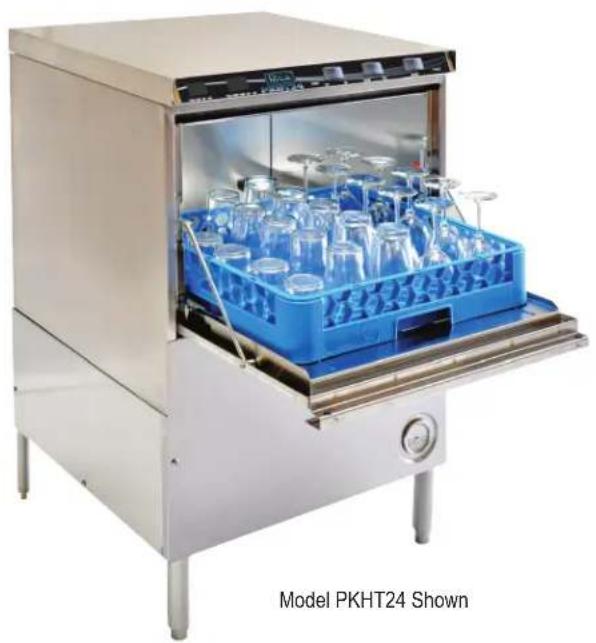
Commercial Glasswasher
Model PKHT24

Note: Some US States may require Energy Star ratings for Commercial Dishwashers. The specifier or installer is responsible for knowing their local codes, standards, and regulatory requirements.
Form No. Z2346
Rev. 10.25.22
TABLE OF CONTENTS
Introduction....3
Specifications 4
PKHT24 Operational Cycle 5
Getting Started....6
Receiving and Installation....6
Electrical....6
Plumbing....6
BETA Detergent and Rinse Dispenser 7
Safety-Temp Feature 8
Booster Heater Setup....9
Installer Checklist 9
Operation....10
Dema Flow Disc 10
Rinse and Wash Temperatures 10
Startup Procedures....10
Operating and Cleaning Instructions 11
Preventative Maintenance Chart 12
Quick Service Guide....13
Troubleshooting....14
Parts Kits....16
Customer Notice....17
Electrical Diagrams 18
The PKHT24 is a hot water sanitizing, single rack, undercounter glasswasher. It is a stand-alone machine featuring a self-contained booster heater. The only external connections necessary are power supply, water supply, drainpipe, and optional chemical dispensers. The machine uses re-circulated wash water and fresh water final-rinse.
Operation of the PKHT24 is extremely user friendly. To initially fill the machine each day, push the switch marked "FILL". The machine is full when water begins to flow into the scrap tray. The booster tank heater will maintain the wash water temperature at 155° F. The booster heater will produce a minimum of 180° F final rinse water each cycle.
The supply water to the PKHT24 must be a minimum of 140° F at 24 psi (Pounds per Square Inch) with a 6 gpm (Gallons Per Minute) flow rate and 60 gph (Gallons Per Hour) recovery rate. The pipe supplying the water must be a minimum of a 1/2". The plumbing connection is located at the back of the machine. (See specification sheet). The drain is a 1" barbed fitting on the back of the machine for easy attachment of your drain hose.
This manual provides a complete reference guide to the PKHT24. The first section explains how the machine is packaged and what to look for when receiving the machine. This manual explains how to install and set up the machine for use. Requirements are given for plumbing, wiring, and space considerations. These are always taken into consideration by our well-trained sales representatives prior to the order being placed. In the manual, guidance is also given for installation to ensure that the machine will be able to run at optimum conditions.
The machine's functions are mostly automatic and take little training to put into full operation. The Operation section of the manual may be used for instruction and procedures when required. We make this portion of the manual easy to understand so that all levels of operators are able to understand the machine's operation. The Operation section also includes diagnostic considerations for the machine when problems occur.
We are committed to providing the best products and customer service, and we welcome your feedback.
SPECIFICATIONS
| WATER CONSUMPTION | ||
| PER RACK | .75 GAL. | (2.83 L) |
| PER HOUR | 17.9 GAL. | (67.6 L) |
| OPERATING CYCLE | ||
| WASH TIME-SEC | 94 | 94 |
| RINSE TIME-SEC | 16 | 16 |
| DWELL TIME-SEC | 10 | 10 |
| TOTAL CYCLE | 2 MIN. | 2 MIN. |
| OPERATING CAPACITY | ||
| RACKS PER HOUR | 30 | 30 |
| WASH TANK CAPACITY | 2.5 GAL. | (9.46 L) |
| PUMP CAPACITY | 38 GPM | (144 LPM) |
| WATER REQUIREMENTS | ||
| REQUIRED MINIMUM TEMP. * | 110°F | (43°C) |
| RECOMMENDED TEMP. ** | 140°F | (60°C) |
| WATER INLET | 1/2" | 1.27cm |
| DRAIN CONNECTION | 1" | 2.54cm |
| RINSE PRESSURE SET | 20 PSI±5 PSI | 1.41 kg/cm2 |
| CYCLE TEMPERATURES | ||
| WASH-°F | 150°F -160°F | (65.5°C/71°C) |
| RINSE -°F | 180°F -195°F | (82°C/90°C) |
| FRAME DIMENSIONS | ||
| DEPTH | 25" | (63.5 cm) |
| WIDTH | 24" | (60.96 cm) |
| HEIGHT | 33 1/4" | (84.45 cm) |
| MAX CLEARANCE FOR GLASSWARE | 11-1/4" | (28.6 cm) |
| ELECTRICAL RATING* | 208 VOLTS1 PH—60 Hz | 230 VOLTS1 PH—60 Hz |
| 33 AMPS | 35 AMPS | |
| BOOSTER HEATER | 5.3 kW | 6.5 kW |
| WASH PUMP MOTOR | 3/4 HP | 3/4 HP |
| THIS SYSTEM REQUIRES THREE POWER WIRES, WHICH INCLUDES A CURRENT CARRYING NEUTRAL. AN ADDITIONAL FOURTH WIRE MUST BE PROVIDED FOR MACHINE GROUND. | ||
| SHIPPING WEIGHT | 234# | (106 kg) |
* For machines having "SAFETY TEMP" feature. ** For faster heat recovery.
OPERATIONAL CYCLE
The PKHT24 operational cycle has a total cycle time of 2 minutes (120 seconds). The Timing Diagram and the steps listed below detail the individual functions that are executed during each operational cycle.
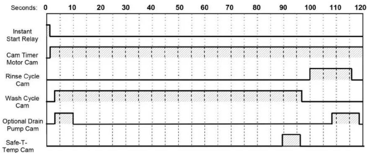
- With the machine powered up, toggling the START switch begins a cycle.
a) Toggling the START switch energizes both the Cam Timer motor and the Instant Start Relay. The Instant Start Relay latches ON the power to the Cam Timer motor so that the START switch can be released a moment after it has been toggled without the Cam Timer motor losing power.
b) After about 1.5 seconds the Cam Timer's first cam — the Cam Timer Motor Cam — latches ON the power to the Cam Timer motor and drops out the Instant Start Relay. The Cam Timer motor continues to run for a total of 2 minutes, at which time it switches OFF — resetting the Cam Timer — and waits for the next START command.
-
The Cam Timer's third cam controls the Wash Pump. The Wash Pump comes ON about 3 seconds into the Operational Cycle and continues to run for 94 seconds. This 94-second period is the Wash Cycle.
-
At the same time that the Wash Pump comes ON the Cam Timer's fourth cam powers ON the Optional Drain Pump — if one is present — and keeps it running for about 7 seconds before powering OFF. This cam turns ON again midway through the Rinse Cycle and stays ON for 10 seconds, turning OFF 2 seconds after the Rinse Cycle has completed.
-
About 3 seconds after the Wash Cycle has completed the Cam Timer's second cam, which controls the Rinse Cycle, turns ON — energizing the Water Solenoid — and stays ON for 16 seconds. This 16-second period is the Rinse Cycle.
-
When the Cam Timer assembly approaches the final rinse portion of the cycle, the "Safe-T-Temp" sixth micro switch will pause Cam Timer assembly if the booster heater has not reached 180 degrees. The machine will remain in wash cycle mode until 180-degree rinse temperature is reached, and at this time the Cam Timer will advance automatically into the rinse cycle and dispense 180 degrees rinse water over the dishes.
GETTING STARTED
Receiving and Installation
The glasswasher is shipped from the factory in a corrugated box on a wooden pallet. The installation guidelines give a systematic procedure for setting up the machine.
Start by removing the packaging material. Unwrap the machine and check for the following component parts:
The Wash Tank Scrap Screen is shipped inside the wash cavity of the machine. This screen must be in place during operation. It has been designed to perform two basic functions:
- Strain water that is circulating through the spray arms and pump assembly.
- A basket to catch broken glass, or heavy solids that may plug the impeller.
Set the machine in place, and level from side-to-side and front-to-back.
Electrical 1
Single-phase 230 volt, 60 Hz dedicated circuit should be used to supply electrical energy to the PKHT24 Glasswasher (see specification sheet on page 4). This system requires three power wires, which include a current carrying neutral. An additional fourth wire must be provided for ground. Approximately 4-feet of 3/4 flexible conduit with power leads (L-1, L-2, Neutral and Ground) extending out of the conduit are provided for easily connecting the power at installation. The power connection must be located such that there is sufficient length of the flexible conduit remaining to permit the machine to be moved for cleaning.
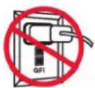
DO NOT USE POWER CORD OR GFI OUTLET
This unit MUST BE hard-wired to a dedicated appropriately sized circuit breaker.
Plumbing 2
The machine is equipped with a 1/2" NPT connection located at the lower left-hand corner (facing the back) of the machine. A 140°F water line should be plumbed to this point (see specification sheet). The water line used must be of sufficient length and flexibility to permit the machine to be moved for cleaning.
1,2 All electrical and plumbing connections must be made by a qualified person who will comply with all available federal, state, and local health, electrical, plumbing and safety codes.

WARNING: California Prop 65 Notice
These products may expose you to chemicals including Chromium, which are known to the state of California to cause cancer and birth defects or other reproductive harm. For more information on whether a product in this list contains these chemicals, please refer to the specific product page at perlick.com. Or to find out more about Prop 65, go to P65Warnings.ca.gov.
WARNING: If water pressure exceeds 50 psi, pressure reducing valve (PRV) is recommended. The supply water to the PKHT24 must be a minimum of 140°F at 24 psi (Pounds per Square Inch) with a 6 gpm (Gallons Per Minute) flow rate and 60 gph (Gallons Per Hour) recovery rate. The pipe supplying the water must be 1/2 " minimum. The plumbing connection is located at the back of the machine. (See specification sheet on page 4).
The PKHT24 may be supplied with an optional drain pump for elevated drains. For floor gravity drain applications, the drain pump should not be used and a good commercial grade hose needs to be connected to the discharge side of the diverter valve (drain valve) and run to the floor drain. If a drain pump is used with a floor drain, the drain hose must rise 12 to 16" before dropping to the floor drain (to reduce any chance of the pump cavitations).
WARNING: Water hardness greater than 3 grains per gallon requires a water softener to prevent damage to heating elements (scale build-up) and booster tank rinse flow restriction. Rinse flow restriction will cause the booster tank to expand and contract causing metal flex, which will eventually crack the tank.
BETA Detergent And Rinse Dispenser
The built-in Beta Detergent and Rinse Dispenser has easy access for chemical settings behind the front kick panel. Both initial charge and recharge is factory pre-set. Basic settings for both detergent and rinse speed are 50%. Operating fine-adjustment screws on the dispenser can control the amount of chemicals drawn into chemical lines.
![graph TD A["DETERGENT SPEED"] --> B["50%-0%"] C["RINSE SPEED"] --> B B --> D["0%-50%"]](/content/2026/05/957593/images/1f4662e32b68fc0aeda0f5608535b51ae8bddb872bd430e1bf0592b38a9184de.jpg)
Safety-Temp Feature
The Safety-Temp feature assures the final rinse cycle is always at a consistent minimum of 180 degrees.
How it works: The Safety-Temp function operates off the fifth cam (labeled "SafeTtemp") on the timer assembly. When the cam timer assembly completes the wash cycle, and approaches the final rinse portion of the cycle, the Safety-Temp micro switch will drop into the cam slot and pause the cam timer assembly if the booster heater has not reached 180 degrees. The machine will remain in wash cycle mode until 180 degree rinse temperature is met, and at this time the cam timer will advance automatically into the rinse cycle and dispense 180 degrees rinse water over the dishes.
Note: If the Safety-Temp cam is not to be used, it becomes a spare cam.
Safety-Temp Installation Instructions
- Remove the 4 cam timer assembly (note wire colors and wire placement for all 4 cam timer micro switches) and install the 5 cam timer in its place.
- Place all wires removed from 4 cam timer assembly in the exact position on the 5 cam timer assembly.
- The cam timer motor receives (1) yellow wire and (1) white wire (re-connect the yellow wire only from the glasswasher harness to the motor).
- The Safety-Temp 5 cam timer assembly kit includes two white harnesses – connect the white wire with the female bullet connector to the timer motor, the stripped end to the #22/NC on the contactor, and the spade end to the center terminal on the fifth micro switch.
- Connect white wire with male bullet connector from the kit to the white wire with female bullet connector coming from glasswasher harness, stripped end to #21/NC on contactor, and the spade end to the top terminal on the fifth micro switch.
![graph TD A["HEATER CONTACTOR"] --> B["SafeTemp harness"] B --> C["Dishmachine harness"] C --> D["Female bullet connector"] C --> E["Male bullet connector"] F["Male bullet connector"] --> G["White panel"] G --> H["Yellow line"] H --> I["Red line"] I --> J["Yellow line"] J --> K["Blue line"] K --> L["…](/content/2026/05/957593/images/5c304622017ad3381ab0bab352077ad9b184d553395bb189f8eb6a8368db4016.jpg)
Booster Heater Setup
The booster tank must be filled with water before the heating element is energized. For this reason, the "High Limit Switch" has intentionally been disconnected at the factory and will require re-connection before the heating element will turn on.
Follow the procedure below to complete the initial installation:
- Close the door on the machine.
- Turn the Power switch to the "ON" position.
- Hold the "FILL" switch in until water overflows into the scrap tray.
- Turn the Power switch to the "OFF" position.
- Connect the blue wire with the disconnect, identified by a red tag, to the High Limit Switch, which is located behind the thermostat behind the front kick panel.
Installer Checklist
☐ Glasswasher checked for concealed damage
☐ Hot water supply is 140° F (60 C) — minimum
☐ Incoming water supply line is 1/2 " — minimum
☐ Incoming water supply is 6 GPM minimum at 24 psi
☐ Supply circuit breaker for machine is properly sized (50 amp)
☐ Service voltage and phase type are correct to machine data plate
☐ If drain pump is used, drain hose rises 12 to 16" before dropping to drain
☐ Drain hose is installed with air gap (discharge 1" above drain)
☐ Glasswasher is properly grounded
☐ Glasswasher is properly leveled
☐ Machine circuit breaker is labeled "GLASSWASHER"
☐ Machine has been “hard-wired” with correctly sized wire
☐ Booster tank has been filled with water (before High Limit Switch is reset)
☐ High Limit Switch for heater has been reset (after Booster Tank has been filled)
OPERATION
Initial Setup
Dema Flow Disc
The Dema Flow Disc has been placed on the exit side of the water valve. The Flow Disc reduces pressure to the standard recommended 20 psi.
Rinse and Wash Temperatures
- Turn the Power switch to the "ON" position.
- After the machine has warmed up for about ten minutes, note the wash and rinse temperatures. The wash temperature must be 155° F minimum. The rinse temperature must be 180° F minimum. If necessary, adjust the temperatures by removing the front kick panel and turning the thermostat adjustment clockwise to increase, or counterclockwise to decrease. This one adjustment controls both temperatures.
Post Instructions
- Install wall chart and instruct machine operator on proper cleaning and operation of the PKHT24.
Startup Procedures
- Open the door of the machine and check that the scrap screen is in place, and that the spray arms and end plugs are secure.
- Close the door of the machine and turn the Power switch to the "ON" position.
- Hold the fill button about 25 seconds or until the water overflows into the scrap tray.
- Once the water is filled to the proper level, press the rocker switch marked "START" – the machine will automatically begin its cycle.
- Check the machine's operating temperatures and adjust if necessary. See the Rinse and Wash Temperatures section above.
- At the end of the wash period, drain the machine by pushing the rocker switch marked "DRAIN". Clean the wash tank screen and scrap tray screen. Remove and clean the spray arms. (See wall chart instructions).

OPERATING AND CLEANING INSTRUCTIONS FOR MODEL PKHT24 INSTRUCCIONES DE LIMPIEZA Y OPERACION DE MODELO PKHT24


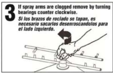
If rinse arm jets are clogged, remove rinse arm (by turning bearing counter clockwise) and clean out rinse jets with paper clip or small pointed object.

Inspect top and bottom spray arms daily. Use toothpick to push debris into spray arm. Remove end plugs and flush with water.

Remove and thoroughly clean scrap tray, and scrap drawer daily.
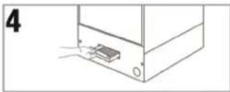
Replace screens after cleaning.

Confirm wash temperature is 155°F.

Check rinse temperature. Minimum 180°F. Notify supervisor if rinse temperature is below 180°F.

Check rinse pressure. Should be 15-22 psi.
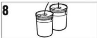
Check chemical containers for product. Confirm correct product line is in the bucket. RED - Detergent BLUE - Rinse Aid

Check machine for leaks.
Quick Service Guide
| TECHNICAL ISSUE CAUSE SOLUTION | ||
| Door leaks | Machine is not level or is leaning forward Adjust machine legs to level | |
| Wash arm end cap is missing Replace end cap | ||
| Door gasket issue Replace gasket | ||
| Thermometer failure | Loose wire at display, board or transformer Secure connectors | |
| Faulty temperature sensing wire Correct, replace | ||
| Faulty temperature sending unit Replace unit | ||
| Faulty transformer Replace transformer | ||
| Scaled heating element Clean scale from heater | ||
| Rinse water temperature too low/high | Booster heater's thermostat not properly set Adjust thermostat | |
| Incoming water temperature to booster heater below 140 F | Adjust external water heater in the facility | |
| Pump motor not running | Loose lead connections Check and crimp connectors | |
| Faulty #3 micro switch Replace micro switch | ||
| Faulty contactor | Replace contactor | |
| Faulty wash pump motor | Replace wash pump motor | |
| Pump motor runs continuously | Faulty #3 micro switch Replace micro switch | |
| Faulty contactor | Replace contactor | |
| Low water pressure in the final rinse | Water regulator not adjusted properly | Adjust regulator to 18-20 psi |
| Clogged final rinse spray jets Clean jets | ||
| Missing final rinse spray end cap Replace end cap | ||
| Low incoming water pressure from facility | Increase pressure to 18-20 psi | |
| Scrap trap overflows overnight | Faulty water solenoid diaphragm | Clean or replace diaphragm |
| Poor cleaning results | Low wash or rinse water temperature | Check temperature settings |
| Wash arm bearing or jets | Clean bearing and arm jets | |
| Rinse arm bearing or jets | Clean bearing and arm jets | |
| Tank discharge screen dirty | Clean screen | |
| Wash tank will not drain | Drain valve not operating | Check power to drain valve |
| Drain valve faulty | Replace drain valve | |
Troubleshooting
| TECHNICAL ISSUE CAUSE SOLUTION | ||
| Machine inoperative | Power off at circuit breaker Reset circuit breaker | |
| Defective power switch Replace power switch | ||
| Motor inoperative | Door is open Close door | |
| Control panel is pulled out Secure control panel | ||
| Defective reed switch Replace reed switch | ||
| Defective timer assembly Replace timer assembly* | ||
| Defective pump motor contactor Replace contactor | ||
| Defective motor Replace motor | ||
| Motor runs with door open | Defective reed switch Replace reed switch | |
| Defective pump motor contactor Replace contactor | ||
| Heater - No heat | High limit switch opened or defective Reset or replace switch | |
| Defective thermostat Replace thermostat | ||
| Defective heater contactor Replace heater contactor | ||
| Defective heater Replace heater | ||
| Heater - Keeps running | Defective thermostat Replace thermostat | |
| Defective heater contactor Replace heater contactor | ||
| Low heat during operation | Low incoming water temperature (below 140 F) | Turn up supply water heater or insulate supply water pipe |
| Thermostat out of adjustment | Adjust thermostat | |
| Cold water mixing with supply | Isolate hot water from cold water | |
| Defective heater Replace heater | ||
| Low rinse water pressure | Pressure regulator out of adjustment | Adjust pressure regulator |
| Defective pressure gauge (actual pressure is fine) | Replace pressure gauge | |
| Regulator at maximum but rinse pressure still low | Insufficient water supply | Supply larger supply line |
| Defective water solenoid valve | Replace water solenoid valve | |
| Low rinse water flow | Low rinse water pressure | See “Low rinse water pressure” in TECHNICAL ISSUE column |
| Rinse arm spray nozzles are limed | De-lime rinse arm spray nozzles | |
| No rinse water flow | Defective water solenoid valve | Replace water solenoid valve |
| Defective (Rinse Relay) ice cube relay | Replace ice cube relay | |
| Rinse water runs with door open | Defective reed switch Replace reed switch | |
* The timer assembly motor or micro switches can be replaced independently if those are the only components that have failed.
Troubleshooting
| TECHNICAL ISSUE CAUSE SOLUTION | ||
| With power on, activating start switch does not begin cycle | Defective start switch (cycle light will not light either) | Replace start switch |
| Defective timer assembly Replace timer assembly* | ||
| Start switch requires >1 second activation to run cycle | Defective (Instant Start) ice cube relay Replace ice cube relay | |
| Activating fill switch does not fill machine | Defective drain/fill switch Replace drain/fill switch | |
| Defective water solenoid valve Replace water solenoid valve | ||
| Fill (rinse water) won't shut off | Defective water solenoid valve Replace water solenoid valve | |
| Defective drain/fill switch Replace drain/fill switch | ||
| Defective timer assembly Replace timer assembly* | ||
| Defective (Rinse Relay) ice cube relay Replace ice cube relay | ||
| Activating drain switch does not drain machine | Drain hose is kinked Un-kink drain hose | |
| Defective drain/fill switch Replace drain/fill | ||
| Cycle light does not light while cycle runs | Defective cycle light Replace cycle light (green) | |
| Power light does not light but machine runs | Defective power light Replace power light (red) | |
| Wash tank or final rinse temperature does not display | Defective digital thermometer Replace digital thermometer | |
| Both the wash tank temperature and the final rinse temperature do not display | Defective thermometer transformer | Replace thermometer transformer |
| Wash tank or final rinse displays wrong temperature | Defective digital thermometer Replace digital thermometer | |
| Defective thermister Replace thermister | ||
* The timer assembly motor or micro switches can be replaced independently if those are the only components that have failed.
PARTS KIT
Parts Kit
| P/N DESCRIPTION Qty. | ||
| 15504.00 Motor Contactor, 2-Pole 20 Amp 1 | ||
| 15504.50 Heater Contactor, 2-Pole 35 Amp 1 | ||
| 00501.00 2 Minute Timer Motor 1 | ||
| 00631.00 Ice Cube Relay 120V 1 | ||
| 00707.00 1/2 Water Solenoid Repair Kit J/E 1 | ||
| 00738.15 Solenoid Coil JE 220V 1 | ||
| 15523.00 Rocker Switch Start Momentary 1 | ||
| 15523.50 Rocker Switch Drain/Fill | 1 | |
| 15524.00 Rocker Switch Power Maintained | 1 | |
| 00556.10 Reed Switch | 1 | |
| 03623.00 1/2" Vacuum Breaker Repair Kit - Watts | 1 | |
| 00707.00 1/2" Water Solenoid Repair Kit - JE | 1 | |
| 04113.00 L1X/L1-C Drain Valve 120V | 1 | |
| 00206.70 Pump Seal Kit | 1 | |
| 13417.89 Heater Thermostat | 1 | |
| 17523.60 High Limit Switch 200F | 1 | |
| 00411.00 Microswitch | 1 | |
| 03203.01 Dual Temperature Display Kit | 1 | |
| 00738.15 Solenoid Coil JE 115V/60Hz | 1 | |
CUSTOMER NOTICE
PKHT24 Installation Guidelines
Improper installation of this product may void the warranty on this machine. Please follow these guidelines for recommended installation and to ensure the warranty of this model is applicable.
Glasswasher Installation Requirements
- Machine must be level. Adjust leveling feet to accommodate uneven floor surfaces.
- Drain height should not exceed maximum height of 16". Connect supplied drain line to three-way valve on back of machine and gravity feed to the floor drain.
- Check the pressure. Recommended pressure is between 18-20 psi.
- Water supply to machine must be a minimum 110° F.
- A four-wire, (neutral, ground and two 110v lines) 220v single phase connection is required. There is a six-foot cord provided with the machine. We recommend a minimum 50-amp dedicated circuit, but you should consult your local building code requirements for proper breaker size.
Activating/Adjusting the Booster Heater
- Booster heater must be filled with water prior to connecting the blue wire from high limit switch. The high limit switch can be found by removing the front panel and locating the red button on the front of the heater tank.
- Once the booster heater has been connected, the thermostat should be adjusted to maintain 180° F during the final rinse cycle. The thermostat is located on the front of the booster tank and is accessible by removing the front panel on the machine.
Automatic Dispensing Equipment
- Applications utilizing automated dispensers for administering ware wash chemicals must use 110v dispenser equipment. There is a 110v power block for installing this equipment inside the control panel.
Electrical Diagram
PKHT24 ELECTRICAL DIAGRAM CONTROL PANEL
Rev.2-5-09
![graph TD A["UPPER COMPONENT TRAY"] --> B["TEMPERATURE SENSING ELEMENTS"] B --> C["RINSE RELAY"] C --> D["110 VAC SWITCHED"] C --> E["110 VAC"] C --> F["SAFETY SWITCH"] C --> G["WATER SOLENOID"] C --> H["NEUTRAL"] C --> I["FILL SWITCH"] C --> J["RUN SIGNAL"] C --> K["START SWITCH"] C --> L["DRAIN SWI…](/content/2026/05/957593/images/cc52005089f76898bcfe2f5573e65b8380c41ceadbafbc5ed8d231b3b7381fc9.jpg)
Electrical Diagram
![graph TD A["CHASSIS GROUND"] --> B["POWER BLOCK"] B --> C["FL1 L2 NEUTRAL"] C --> D["220V + NEUTRAL SINGLE PHASE 50 HZ CONNECTION REQUIRED 3 WIRE# #"] D --> E["115 VAC"] E --> F["TRANSFORMER"] F --> G["CIRCUIT BOARD"] G --> H["RINSE"] H --> I["PUMP MOTOR"] I --> J["4 CAM TIMER"] J --> K["WASH"] K --…](/content/2026/05/957593/images/24c1e166b33167cd88971cbadeb1314839419cda6a38a2df7c7e0c1b53d6df8e.jpg)

Form No.Z2346
Rev. 10.25.22
- TABLE OF CONTENTS
- INTRODUCTION....3
- SPECIFICATIONS 4
- GETTING STARTED....6
- OPERATION....10
- PARTS KITS....16
- ELECTRICAL DIAGRAMS 18
- SPECIFICATIONS
- OPERATIONAL CYCLE
- GETTING STARTED
- RECEIVING AND INSTALLATION
- ELECTRICAL 1
- DO NOT USE POWER CORD OR GFI OUTLET
- PLUMBING 2
- WARNING: CALIFORNIA PROP 65 NOTICE
- BETA DETERGENT AND RINSE DISPENSER
- SAFETY-TEMP FEATURE
- SAFETY-TEMP INSTALLATION INSTRUCTIONS
- BOOSTER HEATER SETUP
- INSTALLER CHECKLIST
- OPERATION
- INITIAL SETUP
- DEMA FLOW DISC
- RINSE AND WASH TEMPERATURES
- POST INSTRUCTIONS
- STARTUP PROCEDURES
- OPERATING AND CLEANING INSTRUCTIONS FOR MODEL PKHT24 INSTRUCCIONES DE LIMPIEZA Y OPERACION DE MODELO PKHT24
- PARTS KIT
- CUSTOMER NOTICE
- PKHT24 INSTALLATION GUIDELINES
- GLASSWASHER INSTALLATION REQUIREMENTS
- ACTIVATING/ADJUSTING THE BOOSTER HEATER
- AUTOMATIC DISPENSING EQUIPMENT
- ELECTRICAL DIAGRAM
Brand : Perlick
Model : PKHT24
Category : Dishwasher